

Page 1
• Apague la computadora y asegúrese de que los contactos del
adaptador estén enteramente ubicados
• en la ranura y asegurados a la computadora con un tornillo de
soporte.
Seteos, Panel de Control y doble clic en Agregar/Quitar
Hardware. (Estos pasos pueden variar según la versión de
• Haga un escaneo del hardware con un clic en Start, Comenzar
ESPAÑOL
Windows). Siga las instrucciones en pantalla para buscar el
adaptador e instalar el driver.
• Instale el adaptador en otra computadora. Si el error persiste,
puede tener un problema de hardware. Contacte a su proveedor
FRANÇAIS
conectados correctamente.
los dispositivos adjuntos.
que su largo no exceda los 100 metros. Para más información
acerca de tipos de cable de red, ver la sección Conexión del
local.
readme/léame del diskette.
del Device Manager.
persiste, puede tener un problema de hardware. Contacte a su
proveedor local.
• Verifique que el/los dispositivo(s) adjunto(s) estén encendidos y
El adaptador no funciona correctamente.
• Haga un Update/Upgrade del driver. Vaya a los archivos
• Controle si hay posibles conflictos de hardware en la ventana
• Instale el adaptador en otra computadora. Si el problema
• Asegúrese de que los adaptadores de red estén funcionando en
El LNK/ACT LED no se enciende al conectarse.
Hardware.
• Verifique que esté en uso el tipo apropiado de cable de red y
Installation Matérielle
que l’imprimante. Puis débranchez l’alimentation de votre
ordinateur.
touchant un objet métallique.
1 Enregistrez votre travail et fermez toutes vos applications.
slot PCI.
2 Eteignez votre ordinateur et vos appareils périphériques, tels
3 Reliez vous à la terre en portant un poignet anti-statique, ou en
Suivez les étapes suivantes pour installer l’adaptateur.
4 Enlevez le couvercle de l’ordinateur et un couvercle de slot d’un
que les contacts de l’adaptateur soient entièrement posés dans
le slot. Si vous souhaitez utiliser la fontion Wake On LAN (WoL),
choisissez un slot PCI le plus proche du connecteur 3-pin WoL
5 Insérez l’adaptateur dans un slot PCI disponible. Assurez vous
Evitez de toucher aux composants électroniques exposés
sur la carte mère de l’ordinateur. Référez vous à la section
Connecter le câble WoL.
ordinateur.
6 Fixez l’adaptateur avec un tourne-vis.
7 Reposez le couvercle de l’ordinateur, branchez et allumez votre
8 Passez à la section Connexion matérielle.
Connecter le câble WoL (Option)
WOL est une fonction optionnelle qui vous permet de dèmarrer votre
ordinateur à distance. Procédez à l’installation si votre ordinateur
supporte le Wake On LAN et si vous souhaitez utiliser cette fonction.
Référez vous au guide d’information de votre carte mère pour de plus
éteindre votre ordinateur et vous assurer que l’adaptateur soit
bien inséré dans le slot.
l’adaptateur. Connectez l’autre extrémté au connecteur 3-pin
1 Suivez les étapes de la section Installation Matérielle pour
amples informations.
WoL sur la carte mère de l’ordinateur.
2 Une extrémité du câble WoL doit déjà être connectée à
3 Remettez le couvercle de l’ordinateur.
Connexion Matérielle
información.
información.
VITESSE TYPE DE CABLE RESEAU
10 Base-T 100Ω 2-paire UTP/STP Catégorie 3, 4 ou 5
100 Base-TX 100Ω 2-paire UTP/STP Catégorie 5
1000 Base-T 100Ω 4-paire UTP/STP Catégorie 5
Assurez vous que la longueur de câble entre les connexions
Utilisez des câbles Ethernet à paire torsadée non blindés (UTP) ou
blindés (STP). Le tableau suivant décrit les types de câbles réseau
utilisés pour différentes vitesses de connexion.
n’excède pas 100 mètres.
Connectez une extrémité du câble Ethernet à l’adaptateur et l’autre
extrémité au switch/hub ou à l’ordinateur. Puis contrôlez les LED.
• Stellen Sie sicher, dass die richtigen Netzwerkkabeltypen
WoL-Kabel-Anschluß (optional)
verwendet werden und die Kabellänge 100 Meter nicht
überschreitet. Für weitere Informationen zu den
WOL ist eine optionale Funktion, mit der Sie den Computer über das
Netzwerk starten können. Wenn Ihr Computer Wake On LAN
Netzwerkkabeltypen siehe Hardware-Anschluß.
unterstützt und Sie diese Funktion verwenden wollen, fahren Sie mit
der Installation fort. Weitere Information finden Sie im
Encendi-do El puerto está conectado a una red.
Parpa-deando El puerto está recibiendo o transmitiendo
Apaga-do El puerto no está recibiendo ni transmitiendo
impresora. Luego desconecte el cable transmisor de energía de
la computadora de la fuente de energía.
1 Guarde su trabajo y cierre todo los programas.
o tocando un objeto de metal.
2 Apague la computadora y los dispositivos periféricos, como la
3 Póngase en cable a tierra mediante una muñequera antiestática
Instalación del Hardware
Siga los siguientes pasos para instalar el adaptador.
Schritte aus, um den Computer auszuschalten und stellen Sie
sicher, daß der Adapter richtig im Steckplatz sitzt.
angeschlossen sein. Schließen Sie das andere Ende an den 3-
2 Ein Ende des WoL-Kabels sollte an den Adapter schon
Pin WoL-Steckverbinder auf der Hauptplatine an.
3 Bringen Sie die Computerabdeckung wieder an.
1 Führen Sie die im Kapitel Hardware-Installation beschriebenen
Benutzerhandbuch Ihrer Hauptplatine.
4 Retire la tapa de la computadora y la tapa de una ranura PCI.
Hardware-Anschluß
Verwenden Sie UTP (nicht abgeschirmtes) oder STP
(abgeschirmtes) Ethernet-Kabel. Die folgende Tabelle zeigt die
Netzwerkkabel-Typen, die für die verschiedenen
Evite tocar los componentes electrónicos expuestos.
Verbindungsgeschwindigkeiten verwendet werden.
Asegúrese de que los contactos del adaptador estén
enteramente ubicados en la ranura. Si usted desea usar la
función Wake On LAN (WoL), elija la ranura PCI más cercana al
5 Inserte el adaptador en una ranura PCI que esté disponible.
GESCHWINDIGKEIT NETZWERKKABEL-TYP
10 Base-T 100Ω 2-Paar UTP/STP Kategorie 3, 4 oder 5
100 Base-TX 100Ω 2-Paar UTP/STP Kategorie 5
conector WoL de 3 pines en el motherboard de la computadora.
1000 Base-T 100Ω 4-Paar UTP/STP Kategorie 5
Vea la sección Conexión del Cable WoL.
6 Asegure el adaptador al chasis con un tornillo de soporte.
7 Vuelva a poner la tapa de la computadora y enciéndala.
8 Continúe en la sección Conexión del Hardware.
Conexión del Cable WoL (Opcional)
WOL es una funciûn opcional que le permite iniciar su ordenador a
distancia. Continúe con la instalación si su computadora soporta
Die Kabellänge zwischen Anschlüssen darf 100 m nicht
überschreiten.
Schließen Sie ein Ende des Ethernet-Kabels an den Adapter und das
andere Ende an einen Switch/Hub oder Computer an. Dann
überprüfen Sie die LED.
LED-Panel
Die LED-Anzeigen liefern Information in Realzeit über den
apagar la computadora y asegurarse de que el adaptador esté
enteramente ubicado en la ranura PCI.
adaptador. Conecte el otro extremo al conector WoL de 3-pin en
1 Siga los pasos en la sección Instalación del Hardware para
Wake On LAN y si usted desea utilizar esta función. Vea su manual
del usuario del motherboard para mayor información.
Ein Der Port ist mit 10, 100 oder 1000 Mbps mit einem Netzwerk
LED STATUS BESCHREIBUNG
LINK/
Adapterstatus.
el motherboard de la computadora.
2 Un extremo del cable WoL debería estar ya conectado al
3 Ponga la tapa de la computadora.
Conexión del Hardware
Utilice cable par trenzado sin blindar (UTP) o par trenzado blindado
verbunden.
Blinkend Datenempfang / Datenübertragung
Aus Kein Datenempfang / Keine Datenübertragung
ACT
Hardware-Konfiguration und -Diagnose
Das ist nur für erfahrene Benutzer. Wenn es nicht absolut notwendig
ist, müssen Sie Ihre Standard-Hardware-Konfiguration nicht ändern.
Verwenden Sie das auf der CD enthaltene Programm Diag32.exe,
VELOCIDAD TIPO DE CABLE DE RED
10 Base-T 100Ω 2-par UTP/STP Categoría 3, 4 o 5
100 Base-TX 100Ω 2-par UTP/STP Categoría 5
1000 Base-T 100Ω 4-par UTP/STP Categoría 5
Asegúrese de que el largo del cable entre las conexiones no exceda
(STP) Ethernet. La siguiente tabla describe los tipos de cable de red
que se usan para las diferentes velocidades de conexión.
um die Hardwarekonfiguration des Adapters auf die
Netzwerkanforderungen einzustellen und/oder eine Diagnose
durchzuführen.
Treiber-Installation
los 100 metros (328 pies).
Conecte un extremo del cable Ethernet al adaptador y el otro
extremo a un conmutador/hub o computadora. Después controle el
LED.
LED del panel
Das Windows-System kann, abhängig von der Microsoft Windows-
Version, den Adapter automatisch erkennen. Folgen Sie den
Anweisungen in den Readme-Dateien, damit Ihr Betriebssystem die
Treiber-Installation abschließt (dazu benötigen Sie evtl. Ihre
Windows-CD).
Fehlersuche
Fehlersuche
Windows kann den Adapter nicht automatisch erkennen.
LED ESTA-DO DESCRIPCIÓN
LNK/
Los indicadore del LED dan información de tiempo real acerca del
estado del adaptador.
Schritte aus, um den Computer auszuschalten und stellen Sie
• Führen Sie die im Kapitel Hardware-Installation beschriebenen
ACT
sicher, dass der Adapter richtig im PCI-Steckplatz sitzt und mit
einer Schraube am Gehäuse des Computers befestigt ist.
Einstellungen, Hardware (Hinzufügen/Entfernen). Je nach
Windows Version können die Schritte variieren. Folgen Sie den
• Machen Sie einen Hardware-Scan durch einen Klick auf Start,
Configuración del Hardware y Diagnóstico
Este punto es sólo para usuarios experimentados. No es necesario
Anleitungen auf dem Bildschirm, um den Adapter zu suchen und
den Treiber zu installieren.
der Fehler noch immer auf, könnte ein Hardware Problem
vorliegen. Bitte nehmen Sie Kontakt zu Ihrem Händler auf.
• Installieren Sie den Adapter auf einem anderen Computer. Tritt
cambiar la configuración de fábrica del hardware a menos que sea
imprescindible.
Use el programa Diag32.exe en el Disco de Instalación para
Dateien auf der Diskette.
• Aktualisieren/Erweitern Sie den Treiber. Lesen Sie die Readme-
Der Adapter funktioniert nicht ordnungsgemäß.
configurar el adaptador y realizar un diagnóstico del hardware. Usted
debe hacer correr este programa exclusivamente con la ventana de
• Überprüfen Sie im Fenster Geräte-Manager, ob Hardware-
Konflikte vorliegen.
indicación de comando de DOS.
• Installieren Sie den Adapter auf einem anderen Computer. Tritt
der Fehler immer noch auf, könnte ein Hardware-Problem
Instalación del Driver
Dependiendo de la versión de Microsoft Windows, el sistema
vorliegen. Bitte nehmen Sie Kontakt mit der zuständigen
Vertretung auf.
Windows puede detectar automáticamente al adaptador. Siga las
instrucciones de los archivos readme/léame de su sistema operativo
en el Disco de Instalación para completar la instalación del driver
(puede necesitar su CD de Windows).
und richtig angeschlossen sind.
• Überprüfen Sie, ob die angeschlossenen Geräte eingeschaltet
Die LINK/ACT LED leuchtet nicht, obwohl das Gerät/Kabel
angeschlossen ist.
Solución de Problemas
• Stellen Sie sicher, dass der Netzwerkadapter und die
Windows no auto-detecta el adaptador.
angeschlossenen Geräte kompatibel sind.
Connect one end of the Ethernet cable to the adapter and the other
end to a switch/hub or computer. Then check the LEDs.
Panel LEDs
The LED indicators give real-time information about the status of the
Cable length between connections must not exceed 100 meters (328
feet).
adapter.
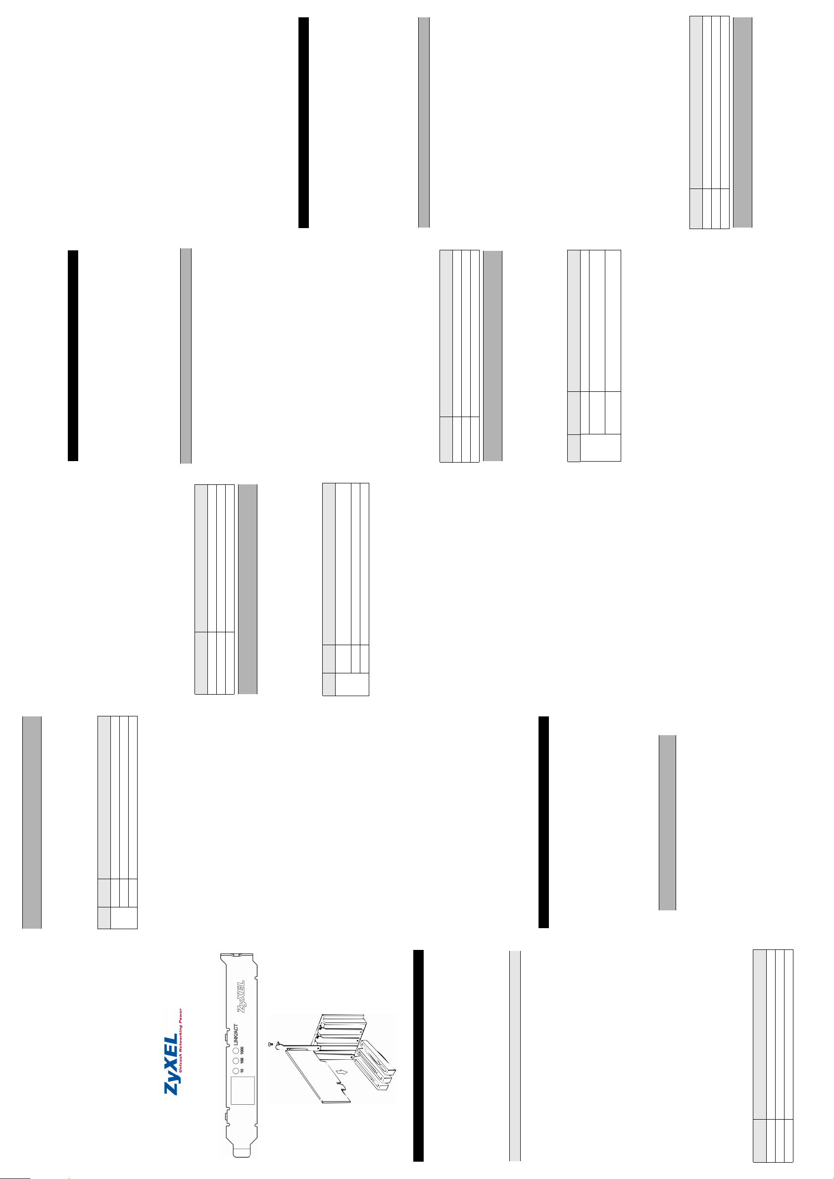
User’s Guide
GN-600 Series
Gigabit PCI Ethernet Adapter
LED STATUS DESCRIPTION
DEUTSCH
On The port is connected to a network at 10, 100 or 1000 Mbps.
Blinking The port is receiving or transmitting data.
Off The port is not connected to a network.
LINK/
ACT
Hardware Configuration and Diagnostics
adapter hardware configuration for your network needs and/or
perform diagnostics. Run the program under pure DOS command
Use the Diag32.exe program in the included CD to set up the
prompt window.
Driver Installation
Follow the instructions in the readme files for your operating system
on the Installation Disk to complete the driver installation (you may
need your Windows CD).
Troubleshooting
The default hardware configuration of the adapter has been designed
to work right out of the box.
5/2005
Version 3.00
Windows does not auto-detect the adapter.
• Turn off the computer and make sure the adapter’s contacts are
fully seated in the slot and secured to the computer with a
bracket screw.
Panel and double-clicking Add/Remove Hardware. (Steps may
vary depending on the version of Windows). Follow the on-
screen instructions to search for the adapter and install the
driver.
may have a hardware problem. Contact your local vendor.
diskette.
window.
you may have a hardware problem. Contact your local vendor.
connected.
devices.
not exceed 100 meters. For more information on network cable
• Perform a hardware scan by clicking Start, Settings, Control
• Install the adapter in another computer. If the error persists, you
• Update/Upgrade the driver. Refer to the readme files on the
• Check for possible hardware conflicts in the Device Manager
• Install the adapter in another computer. If the problem persists,
• Verify that the attached device(s) is turned on and properly
The adapter is not working properly.
• Make sure the network adapters are working on the attached
The LINK/ACT LED does not light up when connected.
• Verify that proper network cable type is used and its length does
types, see the Hardware Connection section.
Hardware-Installation
Führen Sie folgende Schritte aus, um den Adapter zu installieren.
1 Speichern Sie Ihre Arbeit und schließen Sie alle Programme.
2 Schalten Sie den Computer und die Peripheriegeräte (wie z.B.
Drucker) aus. Dann ziehen Sie das Netzkabel des Computers
aus der Steckdose.
oder durch Berühren eines metallischen Objektes.
3 Erden Sie sich durch ein antistatisches Band am Handgelenk
ENGLISH
Berühren Sie auf keinen Fall die freigelegten
elektronischen Komponenten!
eines PCI-Steckplatzes.
4 Entfernen Sie die Computerabdeckung und die Abdeckung
5 Stecken Sie den Adapter in einen freien PCI-Steckplatz. Achten
Sie dabei darauf, dass die Kontaktleiste des Adapters richtig im
Steckplatz sitzt. Möchten Sie die WoL (Wake on LAN) Funktion
verwenden, wählen Sie einen freien PCI-Steckplatz in der Nähe
des 3-Pin WoL-Steckverbinders auf der Hauptplatine (Siehe
WoL-Kabel-Anschluß).
einer Schraube.
Ihren Computer ein.
6 Befestigen Sie den Adapter am Gehäuse des Computers mit
7 Bringen Sie die Computerabdeckung wieder an und schalten Sie
8 Gehen Sie zu Hardware-Anschluss.
a metal object.
1 Save your work and close all programs.
2 Disconnect the computer power cord from the power source.
3 Ground yourself by wearing an anti-static wrist strap or touching
Hardware Installation
Follow the steps below to install the adapter.
4 Remove the computer cover and a slot cover from a PCI slot.
adapter’s contacts are fully seated in the slot. If you wish to use
the Wake On LAN (WoL) function, choose an available PCI slot
closest to the 3-pin WoL connector on the computer
5 Insert the adapter into an available PCI slot. Make sure the
Avoid touching the exposed electronic components.
6 Secure the adapter to the chassis with a bracket screw.
7 Replace the computer cover and power on your computer.
8 Proceed to the Hardware Connection section.
Connecting WoL Cable (Optional)
WOL is an optional function that allows you to remotely start your
computer. Proceed with the installation if your computer supports
motherboard. Refer to Connecting WoL Cable section.
Wake On LAN and that you wish to use this function. Refer to your
the computer and make sure the adapter is fully seated in the
PCI slot.
adapter. Connect the other end to the 3-pin WoL connector on
2 One end of the WoL cable should already be connected to the
the computer motherboard.
3 Replace the computer cover.
Hardware Connection
The following table describes the types of network cable used for the
SPEED NETWORK CABLE TYPE
10 Base-T 100Ω 2-pair UTP/STP Category 3, 4 or 5
100 Base-TX 100Ω 2-pair UTP/STP Category 5
different connection speeds.
1000 Base-T 100Ω 4-pair UTP/STP Category 5
1 Follow the steps in the Hardware Installation section to turn off
motherboard user’s guide for more information.
Page 2
Warnings and Warranty
表硬體可能有問題,請與您當地的供應商連絡。
• 查看裝置管理員中是否有硬體衝突的情況發生。
• 試著在另一部電腦上安裝此一片網卡 . 如果問題持續出現,代
• 確認與網卡連結的裝置是被打開而且正常的連線。
路線的選用請參照網路連結的部分。
• 確認網卡是與這個裝置連線。
• 確認適當種類的網路線被選用而且長度沒有超過100米. 關於網
連結時 LINK/ACT 燈不亮
устранена, возможно, имеет место аппаратная
неисправность. Свяжитесь с местным поставщиком
оборудования.
• Уст ано вит е адаптер в другой компьютер. Если проблема не
Светодиод LINK/ACT LED при подключении не загорается.
устройствах работают.
правильно подсоединено.
• Проверьте, что подключенное устройство(-а) включено и
• Убедитесь, что сетевые адаптеры на подключенных
Подключение оборудования.
подробной информации по типам сетевых кабелей, см. раздел
типа, и его длина не превышает 100. Для получения более
Убедитесь, что используется сетевой кабель соответствующего
Interference Statement
This device complies with Part 15 of the FCC rules. Operation is
subject to the following two conditions:
中文
interference that may cause undesired operations.
1 This device may not cause harmful interference.
2 This device must accept any interference received, including
1 儲存您的工作並關閉所有程式。
硬體安裝
請依照以下步驟安裝此網卡。
FCC Warning
2 關閉電腦及週邊設備,然後從電源插座拔掉電源線。
This equipment has been tested and found to comply with the limits
for a Class B digital device, pursuant to Part 15 of the FCC Rules.
These limits are designed to provide reasonable protection against
harmful interference in a commercial environment. This equipment
generates, uses, and can radiate radio frequency energy and, if not
installed and used in accordance with the instruction manual, may
cause harmful interference to radio communications. Operation of
this equipment in a residential area is likely to cause harmful
interference in which case the user will be required to correct the
interference at his own expense.
CE Mark Warning
This is a class B product. In a domestic environment this product may
cause radio interference in which case the user may be required to
take adequate measures.
Certifications
Refer to the product page at www.zyxel.com.
ZyXEL Limited Warranty
ZyXEL warrants to the original end user (purchaser) that this product
is free from any defects in materials or workmanship for a period of
up to two (2) years from the date of purchase. During the warranty
period and upon proof of purchase, should the product have
indications of failure due to faulty workmanship and/or materials,
ZyXEL will, at its discretion, repair or replace the defective products
or components without charge for either parts or labor and to
whatever extent it shall deem necessary to restore the product or
components to proper operating condition. Any replacement will
consist of a new or re-manufactured functionally equivalent product
of equal value, and will be solely at the discretion of ZyXEL. This
warranty shall not apply if the product is modified, misused, tampered
with, damaged by an act of God, or subjected to abnormal working
conditions.
Note
Repair or replacement, as provided under this warranty, is the
exclusive remedy of the purchaser. This warranty is in lieu of all other
warranties, express or implied, including any implied warranty of
merchantability or fitness for a particular use or purpose. ZyXEL shall
in no event be held liable for indirect or consequential damages of
any kind of character to the purchaser.
To obtain the services of this warranty, contact ZyXEL's Service
Center for your Return Material Authorization number (RMA).
Products must be returned Postage Prepaid. It is recommended that
the unit be insured when shipped. Any returned products without
proof of purchase or those with an out-dated warranty will be repaired
or replaced (at the discretion of ZyXEL) and the customer will be
billed for parts and labor. All repaired or replaced products will be
shipped by ZyXEL to the corresponding return address, Postage
Paid. This warranty gives you specific legal rights, and you may also
have other rights that vary from country to country.
狀態 描述
恆亮 巳連結到網路。連線速度為 10Mbps, 100Mbps 或 1000Mbps。
閃爍 正在接收或傳送資料。
喚醒功能線章節
密合如果您想使用網路喚醒功能,請選擇一可用的 PCI 插槽並
3 手腕戴上靜電環或觸摸金屬部分以使自己接地。
將您的 WoL 線連接到主機板 3-pin 的連接器上請參考連接網路
4 打開電腦機殼並移除一個可用的 PCI 槽之擋板。
避免觸摸網路卡上的電子零件。
5 將網路卡插入一可用的 PCI 插槽中,確認網路卡與PCI 插槽完全
6 使用螺絲將網路卡擋板鎖緊。
7 裝好您的電腦外殼之後請重新開機。
8 繼續硬體連接章節。
連接網路喚醒線 ( 選擇性 )
接上 WoL 線將可從遠端啟動電腦。如果你的電腦支援網路喚醒功能
PCI 插槽上。
pin 連接器上。
1 依照硬體安裝章節的步驟,關閉電腦並確認網路卡緊密地插在
2 WoL 線的一端連結在網卡上,另外一端連接到主機板的WoL 3-
且你想使用這個功能,請執行這一個安裝,你可以從主機板的使用
手冊得到關於 WoL 支援與否的一些相關資訊。
3 把電腦機殼裝回。
硬體連接
以下的表格敘述了適用各種不同的連線速度的網路線。
連線速度 網路線種類
10 Base-T 100W 2-pair UTP/STP Category 3, 4 or 5
100 Base-TX 100W 2-pair UTP/STP Category 5
1000 Base-T 100W 4-pair UTP/STP Category 5
網路線長度在兩個連結中不可超過 100 米 (328 呎 )。
網路線的一端連結在網路卡上,另一端連接交換器、集線器或電腦 ,
然後檢查 LED 的燈號。
擋版 LEDs
LED 指示燈指示此網卡目前的網路工作狀況態。
LED
無亮 並無連結到網路。
LNK/
ACK
硬體設定及診斷
預設的網卡硬體設定已經預設為最佳之使用狀態。
如果有特殊需求需要更改硬體設定及診斷,可以使用附在安裝磁片
中的 Diag32.exe 程式 . 這個程式需要運作在 DOS 的環境下
會需要您的 Windows 視窗安裝光碟 )。
軟體安裝
依照磁片中的 readme 檔案完成整個軟體的安裝過程 ( 此時您可能
故障排除
絲是否已經鎖緊。
應不同 Windows 操作步驟,可能有些許不同的 ) 依照螢幕上
• 關機,確認網卡是否已經緊密地安裝在 PCI 插槽上,檔片上的螺
的指示搜尋網卡及安裝軟體。
• 按下開始、控制台、雙擊新增移除硬體然後執行硬體掃描 . ( 因
Windows 無法自動偵測到網卡
表硬體可能有問題,請與您當地的供應商連絡。
• 試著在另一部電腦上安裝此一片網卡 . 如果問題持續出現,代
• 更新或升級軟體 . 參閱磁片中的讀我檔案 (readme)
網卡工作狀態不正常
или 1000 Мбит/с.
Гор ит По рт подключен к сети на скорости 10, 100
Мигает Порт принимает или передает данные.
Не горит Порт не подключен к сети Ethernet.
ЦВЕТ СТАТУС ОПИСАНИЕ
Зелены
й
WOL на системной плате компьютера.
адаптеру. Другой конец подключите к 3-штыревому разъему
оборудования, чтобы выключить компьютер и убедиться, что
контакты адаптера вошли в слот полностью. Если вы хотите
5 Вставьте адаптер в свободный слот PCI. Убедитесь, что
6 Закрепите адаптер в корпусе компьютера при помощи
8 Перейдите к разделу Подключение оборудования.
7 Уст ан о вит е на место крышку компьютера и включите
WOL является дополнительной функцией, которая позволяет
Подключение кабеля WOL (по желанию)
руководство пользователя для системной платы вашего
ее использовать. Для получения подробной информации см.
дистанционно запустить компьютер. Продолжайте установку,
если ваш компьютер поддерживает функцию WOL, и вы хотите
питание.
винта.
разъему WOL на системной плате компьютера. См. раздел
Подключение кабеля WOL.
выберите свободный слот PCI, ближа йший к 3-штыревому
использовать функцию WOL (Wake On LAN - включение
компьютера при поступлении сигнала на сетевую карту),
адаптер полностью вставлен в слот PCI.
1 Выполните действия, указанные в разделе Установка
компьютера.
3 Уст ан о вит е на место крышку компьютера.
2 Один конец кабеля WOL должен быть уже подключен к
Подключение оборудования
СКОРОСТЬ ТИП СЕТЕВОГО КАБЕЛџ
10 Base-T 2-парный кабель UTP/STP 100 Ω категории 3, 4 или 5
100 Base-TX 2-парный кабель UTP/STP 100 Ω категории 5
используемые при различных скоростях.
В следующей таблице описываются типы сетевых кабелей,
1000Base-T 4-парный кабель UTP/STP 100 Ω категории 5
Подключите один конец кабеля Ethernet к адаптеру, а другой - к
превышать 100 метров (328 футов).
Длина кабеля между точками подключения не должна
Светодиоды на передней панели
состояние светодиодов.
коммутатору/концентратору или компьютеру. Затем проверьте
СВЕТО
ДИОД
LNK/
состоянии адаптера в режиме реального времени.
Светодиодные индикаторы предоставляют информацию о
ACT
Конфигурация и диагностика оборудования
предназначена для работы без настройки.
Конфигурация оборудования адаптера по умолчанию
поставки компакт-диске. Запускать программу необходимо из
окна командной строки DOS.
используется программа Diag32.exe на входящем в комплект
требованиями вашей сети и/или выполнения диагностики
Для установки конфигурации адаптера в соответствии с
Уст анов к а драйвера
файле readme на установочном диске для вашей операционной
Для завершения установки драйвера следуйте указаниям в
системы (потребуется компакт-диск Windows).
Поиск и устранение неисправностей
полностью и вставлены в слот и адаптер надежно закреплен
в компьютере с помощью винта.
• Выполните поиск устройств, щелкнув Start (Пуск), Settings
• Выключите компьютер и убедитесь, что контакты адаптера
Windows автоматически не определяет новый адаптер.
зависимости от версии Windows). Следуйте инструкциям на
(Настройки), Control Panel (Панель управления) и дважды
оборудования). (Порядок действий может быть разным в
щелкнув Add/Remove Hardware (Устан ов к а
устранена, возможно, имеет место аппаратная
неисправность. Свяжитесь с местным поставщиком
экране для обнаружения
адаптера и установки драйвера.
оборудования.
• Уст ано вит е адаптер в другой компьютер. Если проблема не
Manager (Диспетчер устройств).
• Проверьте наличие конфликтов оборудования в окне Device
• Обновите драйвер. См. файл readme на дискете.
Адаптер работает неправильно.
Русский
il computer e assicurarsi che l’adattatore sia completamente
inserito nello slot PCI.
1 Seguire i passi della sezione Hardware Installation per spegnere
LED du Panneau
Les indicateur de LED donnent des informations en temps réel sur
l’état de l’adatpateur.
all’adattatore. Collegare l’altro capo al connettore pin-3 sulla
2 Un capo del cavo WoL dovrebbe gia essere collegato
LED ETAT DESCRIPTION
On La porta ë collegata a una rete a 10, 100 o 1000 Mbps.
Lampeg. La porta sta ricevendo o trasmettendo dati.
motherboard del computer.
Off La porta non riceve/trasmette dati.
3 Riposizionare la copertura del computer.
Hardware Connection
Usare il twisted pair non schermato (UTP) o i cavi Ethernet a coppia
attorcigliata schermati (STP). La seguente tabella descrive i tipi di
VELOCITA TIPO DI CAVO DI RETE
10 Base-T 100Ω 2-pair UTP/STP Categoria 3, 4 or 5
100 Base-TX 100Ω 2-pair UTP/STP Categoria 5
1000 Base-T 100Ω 4-pair UTP/STP Categoria 5
Assicurarsi che la lunghezza del cavo fra i collegamenti non superi i
cavi di rete usati per le diverse velocità di collegamento.
100 metri.
Collegare un'estremità del cavo Ethernet all'adattatore e l'altra
estremità ad uno switch/hub o computer. Controllare quindi i LED.
Pannelo LED
Gli indicatori del LED forniscono le informazioni in tempo reale sulla
condizione dell'adattatore.
LED STATO DESCRIZIONE
LNK/
ACT
Hardware Configuration and Diagnostics
Questo è unicamente per gli utenti esperti. Non bisogna cambiare la
installazione per configurare l'adattatore e per effettuare la
diagnostica hardware. Lanciare il programma direttamente dal
configurazione hardware di default se non assolutamente
prompt di DOS.
necessario. Usare il programma di Diag32.exe nel dischetto di
Driver Installation
A seconda della versione di Windows, il system di Windows può
rilevare automaticamente l'adattatore. Seguire le istruzioni del file
readme per il vostro sistema operativo sul dischetto di installazione
per completare l'installazione del driver (potreste avere bisogno del
vostro CD di Windows).
Analisi dei Guasti
Windows non rileva automaticamente l’adattatore.
inseriti completamente nello slot e che siano assicurati al
• Spenga il coputer e si assicuri che i contatti dell’ adattatore siano
computer con una vite. Effettui un controllo dell'hardware
cliccando start, impostazioni, pannello di controllo, installazione
applicazioni, selezionare l’adattatore e doppio-ckick su aggiungi/
rimuovi. (i punti possono variare secondo la versione di
Windows). Segua le istruzioni sullo schermo per cercare
l'adattatore e per installare il driver. Installi l'adattatore in altro
computer. Se l'errore persiste, potrebbe essere un problema
hardware. Mettersi in contatto con il vostro fornitore locale.
dischetto. Controlli se ci sono conflitti hardware nella finestra
gestione periferiche di windows. Installi l'adattatore in altro
computer. Se il problema persiste, potrebbe essere un problema
• Update/Upgrade del driver. Fare riferimento al file readme sul
hardware. Mettersi in contatto con il vostro fornitore locale.
L’adattatore non funziona correttamente.
collegata. Si assicuri che gli adattatori della rete stiano agendo
sulle periferiche installate. Verifichi che il tipo di cavo di rete
usato sia adeguato e che la sua lunghezza non superi i 100
metri. Per ulteriori informazioni sui tipi di cavi di rete, veda il
• Verifichi che la periferica sia fissata, accesa e correttamente
Il LED LINK/ACT non si accende quando è connesso.
punto Hardware Connection.
Устано вка оборудования
Для установки адаптера выполните следующие действия.
источника питания.
2 Отсоедините кабель электропитания компьютера от
1 Сохраните данные и закройте все программы.
3 Снимите статическое электричество при помощи
PCI.
антистатического браслета, надев его на запястье, или
прикоснитесь к металлическому предмету.
4 Снимите крышку с корпуса компьютера и заглушку со слота
Старайтесь не касаться открытых электронных компонентов.
ITALIANO
données.
Allumée Le port est connectè à un rèseau à 10, 100 ou 1000 Mbps.
Clignote Le port est en cours de réception ou d’émission de
Eteinte Le port ne reçoit ou n’émet pas de données.
LINK/
ACT
Configuration et Diagnostiques Matériels
Ceci est réservé aux utilisateurs expérimentés. Vous n’avez pas
besoin de changer la configuration matérielle par défaut si ceci n’est
pas absolument nécessaire.
Utilisez le programme Diag32.exe sur la disquette d’installation, pour
configurer l’adaptateur et réaliser les diagnostiques de matériel. Vous
devez lancer le programme sous une fenêtre de commande
purement DOS.
Installation du Pilote
Selon la version de Microsoft Windows, le système Windows peut
détecter automatiquement l’adapateur. Suivez les instructions dans
les fichiers Lisez Moi pour votre système d’opération sur la disquette
d’installation, afin d’effectuer l’installation du pilote (vous aurez peut-
être besoin de votre CD Windows).
Dépannage
l’adaptateur soient bien insérés dans le slot et fixés à l’ordinateur
• Eteignez l’ordinateur et assurez vous que les contacts de
Windows ne détecte pas automatique-ment l’adaptateur.
avec une vis.
Suppression de Matériel. (Les étapes peuvent varier selon la
version de Windows). Suiviez les instructions à l’écran pour
rechercher l’adaptateur et installer le pilote.
vous avez probablement un problème matériel. Contacter votre
Panneau de Configuration et en double-cliquant sur Ajout/
• Effectuez un scan matériel en cliquant Démarrer, Paramètres,
revendeur local.
Lisez-Moi sur la disquette.
fenêtre Gestionnaire de Périphériques.
vous avez probablement un problème matériel. Contacter votre
revendeur local.
• Installez l’adaptateur sur un autre ordinateur. Si l’erreur persiste,
• Effectuez une mise à jour du pilote. Référez vous aux fichiers
• Vérifiez qu’il n’existe pas d’éventuels conflits matériels dans la
• Installez l’adaptateur sur un autre ordinateur. Si l’erreur persiste,
L’adaptateur ne fonctionne pas correctement.
branché.
• Vérifiez que l’appareil connecté soit allumé et correctement
La LED LINK/ACT LED ne s’allume pas lorsqu’elle est connectée.
• Assurez vous que les adaptateurs de réseau fonctionnent sur
longueur ne dépasse pas 100 mètres. Pour plus d’informations
sur les types de câbles réseau, référez vous à la section
les appareils connectés.
Connexion Matériellexion Matérielle.
• Vérifiez que le bon type de câble réseau est utilisé et que sa
Hardware Installation
Seguire i seguenti punti per installare l'adattatore.
1 Salvare il lavoro e chiudere tutti i programmi.
2 Spegnere il computer e le periferiche collegate, come la
stampante. Poi staccare il cavo della corrente dalla presa.
toccando un oggetto di metallo.
3 Isolatevi dalla corrente indossando una fascetta anti-statica o
4 Rimuovere la copertura del computer e quella dello slot PCI.
5 Inserire l'adattatore in uno slot disponibile del PCI. Assicurarsi
Evitare di toccare i componenti elettrici esposti.
che i contatti dell’ adattatore siano completamente inseriti nello
slot. Se desiderate usare il WoL, scegliere uno slot disponibile
del PCI più vicino al connettore dei 3-perni WoL sulla
motherboard del computer. Fare riferimento alla sezione
Collegamento del cavo WoL.
6 Fissare l’adattatore allo chassis con una vite.
7 Riposizionare la copertura del computer ed accenderlo.
8 Procedere come descritto nella sezione Hardware connection.
Connecting WoL Cable (Opzionale)
WOL ë una funzione opzionale che consente di avviare da remoto il
computer. Procedere all'installazione se il vostro computer supporta
la WoL e se desiderate usare questa funzione. Fare riferimento alla
vostra guida utente della motherboard per ulteriori informazioni.
 Loading...