

ZyXEL Gateway 400 User Manual
User Guide
Gateway 400


3
Welcome
Dear customer,
On the following pages we would like to familiarize you with the features of your new Gateway 400.
Please make sure that you definitely read the included Important Notes Quick Start Guide in any
case.
Functionality of your New Gateway 400
The Gateway 400 offers the following features:
ISDN SIP gateway for 4 ISDN Basic Rate Interfaces (8 simultaneous calls)
ISDN BRI point-to-multipoint and point-to-point connections
ADSL2+ Annex A and B/J
VDSL2 30a profile support
Vectoring support to increase the bandwidth of VDSL
GigabitETH-WANoE interface
Integrated router/NAT (double play)
IPv6 support
Audio coding (G.711, G.726, G.729, T.38 fax support)
Internal long-term, stable and highly accurate 5ppm clock
Advanced QoS guarantees double-play service quality
Remote provisioning and management through TR-069
Integrated power supply; prepared for 19“ rack mounting (optional rack mounting kit available)
Supports SIP 2.0, PPPoE, DHCP, SIPconnect 1.1 interoperability
Brief Description
Voice over IP is increasingly replacing analog and ISDN-based transmission technology. This creates
the need to integrate existing ISDN private branch exchanges (PBX) in the new IP environment and
to also provide the ISDN service in an all-IP network.
The ISDN-SIP Gateway 400 provides 4 S0 interfaces on the subscriber side in its basic configuration.
This allows up to 8 simultaneous calls over the IP network. The connection can be made via both a
VDSL2/ADSL2 link and also with an upstream modem/router (e.g., SHDSL) via the WANoE interface.
The provision of a number of supplementary services such as CLIP, CLIR, COLP, COLR, and CFx enable
the professional conversion of voice services on a single IP network.
Due to the integrated router functionality (double play with QoS), the Gateway 400 can also be used
as a router for data services over the same DSL line.
For professional installation in a 19
“ rack, the device can be mounted with appropriate brackets; all
connecting elements and indicators are arranged on the front side, and the power cord is located on
the rear panel

4
Symbols and Notational Conventions
The following symbols and notational conventions are used to highlight specific information in this
manual:
Warnings and Notes
Symbols and Notational Conventions
Attention
Indicates important information and warnings that should always be observed in order
to avoid malfunctions and risks.
Note
Identifies useful hints and tips.
Notational Conventions Example
Bold font is used denote fields and titles of screen dialogs, connections at the Gateway 400 as well as LEDs and buttons
Save
Cancel
Setup Assistant
LAN3
WPS
Paths, folder names and file names C:/Program Files
Downloads
config.bin
Blue font is used to indicate addresses to be entered in the browser
as well as links and references within this manual
http://sphairon.box
http://192.168.100.1
see Symbols and Notational Conventions on page
4
Inputs for operating procedures on the phone are represented with
keyboard symbols

5
Table of Contents
1 Before You Start. . . . . . . . . . . . . . . . . . . . . . . . . . . . . . . . . . . . . . 9
1.1 Prerequisites. . . . . . . . . . . . . . . . . . . . . . . . . . . . . . . . . . . . . . . . . . . . . . . . . . . . . . . . . . . . . . . . . . . . .9
1.2 Package Contents . . . . . . . . . . . . . . . . . . . . . . . . . . . . . . . . . . . . . . . . . . . . . . . . . . . . . . . . . . . . . . . .9
1.2.1 Optional Accessories. . . . . . . . . . . . . . . . . . . . . . . . . . . . . . . . . . . . . . . . . . . . . . . . . . . . . . . . . . . . . .9
1.3 Safety Information . . . . . . . . . . . . . . . . . . . . . . . . . . . . . . . . . . . . . . . . . . . . . . . . . . . . . . . . . . . . . 10
1.4 Computer Settings . . . . . . . . . . . . . . . . . . . . . . . . . . . . . . . . . . . . . . . . . . . . . . . . . . . . . . . . . . . . . 10
1.4.1 Network Settings. . . . . . . . . . . . . . . . . . . . . . . . . . . . . . . . . . . . . . . . . . . . . . . . . . . . . . . . . . . . . . . 11
1.4.2 Fixed IP Address. . . . . . . . . . . . . . . . . . . . . . . . . . . . . . . . . . . . . . . . . . . . . . . . . . . . . . . . . . . . . . . . 11
2 Your Gateway 400. . . . . . . . . . . . . . . . . . . . . . . . . . . . . . . . . . . 12
2.1 Indicators and Ports on the Front Panel . . . . . . . . . . . . . . . . . . . . . . . . . . . . . . . . . . . . . . . . . . . 12
2.2 Indicators and Connectors on the Rear Panel . . . . . . . . . . . . . . . . . . . . . . . . . . . . . . . . . . . . . . 14
2.3 Reset Switch . . . . . . . . . . . . . . . . . . . . . . . . . . . . . . . . . . . . . . . . . . . . . . . . . . . . . . . . . . . . . . . . . . . 14
2.3.1 Restarting the Gateway 400 . . . . . . . . . . . . . . . . . . . . . . . . . . . . . . . . . . . . . . . . . . . . . . . . . . . . . 15
2.3.2 Resetting the Gateway 400 to the Factory Default Settings . . . . . . . . . . . . . . . . . . . . . . . . . 15
3 Installation . . . . . . . . . . . . . . . . . . . . . . . . . . . . . . . . . . . . . . . . . 16
3.1 Installation diagram for S0 bus. . . . . . . . . . . . . . . . . . . . . . . . . . . . . . . . . . . . . . . . . . . . . . . . . . . 18
4 Setup . . . . . . . . . . . . . . . . . . . . . . . . . . . . . . . . . . . . . . . . . . . . . . 20
4.1 Computer Settings . . . . . . . . . . . . . . . . . . . . . . . . . . . . . . . . . . . . . . . . . . . . . . . . . . . . . . . . . . . . . 20
4.2 Carrier Detection . . . . . . . . . . . . . . . . . . . . . . . . . . . . . . . . . . . . . . . . . . . . . . . . . . . . . . . . . . . . . . . 20
5 Configuration . . . . . . . . . . . . . . . . . . . . . . . . . . . . . . . . . . . . . . . 21
5.1 Screen Dialog Layout. . . . . . . . . . . . . . . . . . . . . . . . . . . . . . . . . . . . . . . . . . . . . . . . . . . . . . . . . . . . 21
5.2 Overview . . . . . . . . . . . . . . . . . . . . . . . . . . . . . . . . . . . . . . . . . . . . . . . . . . . . . . . . . . . . . . . . . . . . . . 22
5.3 DSL . . . . . . . . . . . . . . . . . . . . . . . . . . . . . . . . . . . . . . . . . . . . . . . . . . . . . . . . . . . . . . . . . . . . . . . . . . . 23
5.3.1 Monitoring Index. . . . . . . . . . . . . . . . . . . . . . . . . . . . . . . . . . . . . . . . . . . . . . . . . . . . . . . . . . . . . . . 23
5.3.2 Spectrum . . . . . . . . . . . . . . . . . . . . . . . . . . . . . . . . . . . . . . . . . . . . . . . . . . . . . . . . . . . . . . . . . . . . . . 23
5.4 Internet . . . . . . . . . . . . . . . . . . . . . . . . . . . . . . . . . . . . . . . . . . . . . . . . . . . . . . . . . . . . . . . . . . . . . . . 23
5.4.1 Access Setup . . . . . . . . . . . . . . . . . . . . . . . . . . . . . . . . . . . . . . . . . . . . . . . . . . . . . . . . . . . . . . . . . . . 23
5.4.1.1 Internet Access. . . . . . . . . . . . . . . . . . . . . . . . . . . . . . . . . . . . . . . . . . . . . . . . . . . . . . . . . . . . . . . . . 23
5.4.2 Dynamic DNS . . . . . . . . . . . . . . . . . . . . . . . . . . . . . . . . . . . . . . . . . . . . . . . . . . . . . . . . . . . . . . . . . . 24
5.4.3 DNS Relay . . . . . . . . . . . . . . . . . . . . . . . . . . . . . . . . . . . . . . . . . . . . . . . . . . . . . . . . . . . . . . . . . . . . . 25
5.4.4 Static Routing. . . . . . . . . . . . . . . . . . . . . . . . . . . . . . . . . . . . . . . . . . . . . . . . . . . . . . . . . . . . . . . . . . 25
5.5 Telephony . . . . . . . . . . . . . . . . . . . . . . . . . . . . . . . . . . . . . . . . . . . . . . . . . . . . . . . . . . . . . . . . . . . . . 26
5.5.1 General . . . . . . . . . . . . . . . . . . . . . . . . . . . . . . . . . . . . . . . . . . . . . . . . . . . . . . . . . . . . . . . . . . . . . . . 26
5.5.2 VoIP Provider . . . . . . . . . . . . . . . . . . . . . . . . . . . . . . . . . . . . . . . . . . . . . . . . . . . . . . . . . . . . . . . . . . 27
5.5.3 VoIP Accounts. . . . . . . . . . . . . . . . . . . . . . . . . . . . . . . . . . . . . . . . . . . . . . . . . . . . . . . . . . . . . . . . . . 27
5.5.4 VoIP Services. . . . . . . . . . . . . . . . . . . . . . . . . . . . . . . . . . . . . . . . . . . . . . . . . . . . . . . . . . . . . . . . . . . 28
5.5.5 ISDN . . . . . . . . . . . . . . . . . . . . . . . . . . . . . . . . . . . . . . . . . . . . . . . . . . . . . . . . . . . . . . . . . . . . . . . . . . 29
5.5.5.1 Interface Mapping. . . . . . . . . . . . . . . . . . . . . . . . . . . . . . . . . . . . . . . . . . . . . . . . . . . . . . . . . . . . . . 29
5.6 Network. . . . . . . . . . . . . . . . . . . . . . . . . . . . . . . . . . . . . . . . . . . . . . . . . . . . . . . . . . . . . . . . . . . . . . . 30
5.6.1 LAN . . . . . . . . . . . . . . . . . . . . . . . . . . . . . . . . . . . . . . . . . . . . . . . . . . . . . . . . . . . . . . . . . . . . . . . . . . . 30
5.6.1.1 Static Routing. . . . . . . . . . . . . . . . . . . . . . . . . . . . . . . . . . . . . . . . . . . . . . . . . . . . . . . . . . . . . . . . . . 32

6
5.6.2 USB . . . . . . . . . . . . . . . . . . . . . . . . . . . . . . . . . . . . . . . . . . . . . . . . . . . . . . . . . . . . . . . . . . . . . . . . . . . 33
5.6.2.1 Devices. . . . . . . . . . . . . . . . . . . . . . . . . . . . . . . . . . . . . . . . . . . . . . . . . . . . . . . . . . . . . . . . . . . . . . . . 33
5.6.2.2 FTP Server . . . . . . . . . . . . . . . . . . . . . . . . . . . . . . . . . . . . . . . . . . . . . . . . . . . . . . . . . . . . . . . . . . . . . 33
5.6.3 Additional Features. . . . . . . . . . . . . . . . . . . . . . . . . . . . . . . . . . . . . . . . . . . . . . . . . . . . . . . . . . . . . 34
5.6.3.1 Additional Features. . . . . . . . . . . . . . . . . . . . . . . . . . . . . . . . . . . . . . . . . . . . . . . . . . . . . . . . . . . . . 34
5.7 Security . . . . . . . . . . . . . . . . . . . . . . . . . . . . . . . . . . . . . . . . . . . . . . . . . . . . . . . . . . . . . . . . . . . . . . . 34
5.7.1 Firewall . . . . . . . . . . . . . . . . . . . . . . . . . . . . . . . . . . . . . . . . . . . . . . . . . . . . . . . . . . . . . . . . . . . . . . . 34
5.7.1.1 Settings . . . . . . . . . . . . . . . . . . . . . . . . . . . . . . . . . . . . . . . . . . . . . . . . . . . . . . . . . . . . . . . . . . . . . . . 34
5.7.1.2 Schedule Rule . . . . . . . . . . . . . . . . . . . . . . . . . . . . . . . . . . . . . . . . . . . . . . . . . . . . . . . . . . . . . . . . . . 35
5.7.1.3 Firewall Rules . . . . . . . . . . . . . . . . . . . . . . . . . . . . . . . . . . . . . . . . . . . . . . . . . . . . . . . . . . . . . . . . . . 35
5.7.1.4 IP Stack Settings. . . . . . . . . . . . . . . . . . . . . . . . . . . . . . . . . . . . . . . . . . . . . . . . . . . . . . . . . . . . . . . . 35
5.7.1.5 Zone Configuration. . . . . . . . . . . . . . . . . . . . . . . . . . . . . . . . . . . . . . . . . . . . . . . . . . . . . . . . . . . . . 36
5.7.2 Port Forwarding. . . . . . . . . . . . . . . . . . . . . . . . . . . . . . . . . . . . . . . . . . . . . . . . . . . . . . . . . . . . . . . . 36
5.7.2.1 Trigger Ports . . . . . . . . . . . . . . . . . . . . . . . . . . . . . . . . . . . . . . . . . . . . . . . . . . . . . . . . . . . . . . . . . . . 38
5.7.3 IPSec . . . . . . . . . . . . . . . . . . . . . . . . . . . . . . . . . . . . . . . . . . . . . . . . . . . . . . . . . . . . . . . . . . . . . . . . . . 38
5.8 System . . . . . . . . . . . . . . . . . . . . . . . . . . . . . . . . . . . . . . . . . . . . . . . . . . . . . . . . . . . . . . . . . . . . . . . . 39
5.8.1 Protocol Stack. . . . . . . . . . . . . . . . . . . . . . . . . . . . . . . . . . . . . . . . . . . . . . . . . . . . . . . . . . . . . . . . . . 39
5.8.2 Access Protection. . . . . . . . . . . . . . . . . . . . . . . . . . . . . . . . . . . . . . . . . . . . . . . . . . . . . . . . . . . . . . . 42
5.8.3 System Time . . . . . . . . . . . . . . . . . . . . . . . . . . . . . . . . . . . . . . . . . . . . . . . . . . . . . . . . . . . . . . . . . . . 42
5.8.4 Languages . . . . . . . . . . . . . . . . . . . . . . . . . . . . . . . . . . . . . . . . . . . . . . . . . . . . . . . . . . . . . . . . . . . . . 42
5.8.5 Save Configuration . . . . . . . . . . . . . . . . . . . . . . . . . . . . . . . . . . . . . . . . . . . . . . . . . . . . . . . . . . . . . 42
5.8.6 Reset Device . . . . . . . . . . . . . . . . . . . . . . . . . . . . . . . . . . . . . . . . . . . . . . . . . . . . . . . . . . . . . . . . . . . 43
5.8.7 Firmware Update. . . . . . . . . . . . . . . . . . . . . . . . . . . . . . . . . . . . . . . . . . . . . . . . . . . . . . . . . . . . . . . 44
5.8.8 Remote Management. . . . . . . . . . . . . . . . . . . . . . . . . . . . . . . . . . . . . . . . . . . . . . . . . . . . . . . . . . . 44
5.8.9 SSH . . . . . . . . . . . . . . . . . . . . . . . . . . . . . . . . . . . . . . . . . . . . . . . . . . . . . . . . . . . . . . . . . . . . . . . . . . . 44
5.8.10 CWMP . . . . . . . . . . . . . . . . . . . . . . . . . . . . . . . . . . . . . . . . . . . . . . . . . . . . . . . . . . . . . . . . . . . . . . . . 45
5.8.10.1ACS Configuration . . . . . . . . . . . . . . . . . . . . . . . . . . . . . . . . . . . . . . . . . . . . . . . . . . . . . . . . . . . . . . 45
5.8.10.2Client Configuration . . . . . . . . . . . . . . . . . . . . . . . . . . . . . . . . . . . . . . . . . . . . . . . . . . . . . . . . . . . . 45
5.8.11 SNMP . . . . . . . . . . . . . . . . . . . . . . . . . . . . . . . . . . . . . . . . . . . . . . . . . . . . . . . . . . . . . . . . . . . . . . . . . 45
5.8.12 Diagnostics . . . . . . . . . . . . . . . . . . . . . . . . . . . . . . . . . . . . . . . . . . . . . . . . . . . . . . . . . . . . . . . . . . . . 46
5.8.12.1System Messages. . . . . . . . . . . . . . . . . . . . . . . . . . . . . . . . . . . . . . . . . . . . . . . . . . . . . . . . . . . . . . . 46
5.8.12.2Packet Tracer . . . . . . . . . . . . . . . . . . . . . . . . . . . . . . . . . . . . . . . . . . . . . . . . . . . . . . . . . . . . . . . . . . 46
5.8.12.3LED Test . . . . . . . . . . . . . . . . . . . . . . . . . . . . . . . . . . . . . . . . . . . . . . . . . . . . . . . . . . . . . . . . . . . . . . . 46
5.8.13 QoS . . . . . . . . . . . . . . . . . . . . . . . . . . . . . . . . . . . . . . . . . . . . . . . . . . . . . . . . . . . . . . . . . . . . . . . . . . . 46
5.8.13.1Settings . . . . . . . . . . . . . . . . . . . . . . . . . . . . . . . . . . . . . . . . . . . . . . . . . . . . . . . . . . . . . . . . . . . . . . . 46
5.8.13.2Class Creation. . . . . . . . . . . . . . . . . . . . . . . . . . . . . . . . . . . . . . . . . . . . . . . . . . . . . . . . . . . . . . . . . . 47
5.8.13.3Rule Creation . . . . . . . . . . . . . . . . . . . . . . . . . . . . . . . . . . . . . . . . . . . . . . . . . . . . . . . . . . . . . . . . . . 47
5.8.13.4Statistics . . . . . . . . . . . . . . . . . . . . . . . . . . . . . . . . . . . . . . . . . . . . . . . . . . . . . . . . . . . . . . . . . . . . . . 47
6 Frequently Asked Questions . . . . . . . . . . . . . . . . . . . . . . . . . . 48
7 Legal Notices . . . . . . . . . . . . . . . . . . . . . . . . . . . . . . . . . . . . . . . 50
7.1 Disposal . . . . . . . . . . . . . . . . . . . . . . . . . . . . . . . . . . . . . . . . . . . . . . . . . . . . . . . . . . . . . . . . . . . . . . . 53
7.2 CE Declaration of Conformity . . . . . . . . . . . . . . . . . . . . . . . . . . . . . . . . . . . . . . . . . . . . . . . . . . . . 53
8 Technical Data . . . . . . . . . . . . . . . . . . . . . . . . . . . . . . . . . . . . . . 55
9 Passwords . . . . . . . . . . . . . . . . . . . . . . . . . . . . . . . . . . . . . . . . . . 57
10 Glossary . . . . . . . . . . . . . . . . . . . . . . . . . . . . . . . . . . . . . . . . . . . . 59

7
11 Index . . . . . . . . . . . . . . . . . . . . . . . . . . . . . . . . . . . . . . . . . . . . . . 65

8

Before You Start | Gateway 400 User Guide
9
1 Before You Start
This chapter covers the prerequisites for operating the Gateway 400, the package contents, and
safety information. Please read this chapter carefully.
For security reasons, you must define user names and unique passwords during the setup and configuration. In Chapter 9, Passwords, on page 57, you can record all user names and passwords in a
single location for easy access. Simply print this chapter.
1.1 Prerequisites
Please note that the activities described in this manual require specialized skills and should usually
be performed only by trained administrators. Other requirements:
For surfing and making phone calls, you need an ADSL/VDSL2 connection (unlocked by your ISP).
To connect the Gateway 400 to the network device (e.g., switch, computer, NAS, server), the net-
work device must be equipped with an Ethernet port (no less than 10/100 Mbps, 1 Gbps for optimum speed).
For the configuration, you need a computer with a current web browser.
1.2 Package Contents
1 Gateway 400
1 power cord
1 DSL cable, RJ45-TAE (gray)
1 Ethernet cable, RJ45-RJ45 (yellow)
1 Quick Start Guide
1.2.1 Optional Accessories
You can order the following accessories in addition to the package contents supplied with the Gateway 400:
Order No. 954498 - Rack mounting kit (19“ rack shelf or metric ETSI rack)
Order No. 954499 - Wall mount kit
Network termination (NTBA) for ISDN bus power in normal mode
Attention
Ensure that the listed passwords are kept in a safe place to prevent unauthorized access!

Gateway 400 User Guide | Before You Start
10
1.3 Safety Information
Do not open the housing.
Never install the device or insert or disconnect a cable connection during a thunderstorm.
The device is only intended for applications within a building.
The power outlet must be near the equipment and easily accessible.
Lay the cables so that no one can step on or trip over them.
Use a dry cloth to clean the housing.
Avoid direct contact with water. Never immerse the device in water.
Avoid direct sunlight.
Make sure that only terminals that provide TNV-1 voltage or are intended for operation with
TNV-1 circuits are connected to the ISDN interfaces.
RJ45 jacks are used for a number of different interfaces. There is therefore a risk of confusion.
The Gateway 400 features TNV interfaces (Telecommunications Network Voltage) for ISDN connections and SELV interfaces (Safety Extra Low Voltage) for network connections. Make sure
that no TNV and SELV interfaces are connected with one another. SELV devices are not protected
against voltage spikes, which can lead to technical defects or hazards for users. In the event of
a mixup, the devices will not operate as intended.
The device is designed for use as a desktop unit.
However, it can also be mounted in a rack. Please refer to the installation instructions.
USB devices must only be connected with cables of no more than 3 meters (approx. 9 feet).
Cables to SELV interfaces must not exit the building.
Clock lines should only be connected at the remote end as described in the supplied documen-
tation.
The device is designed for use in office and residential areas.
1.4 Computer Settings
In order to enable your computer to automatically connect to the Gateway 400, please check your
LAN settings. The LAN connection on your computer must be set to Obtain an IP address au-
tomatically (DHCP).
Assigning an IP address ensures that network devices on the Internet or on a home network (local
IP network) can be properly addressed. This requires each IP address to be only assigned once. This
automatic assignment of IP addresses can be handled by the Gateway 400 with its built-in DHCP
server (recommended, default setting).
Attention
This is a Class A device. This device can cause radio interference in residential areas. In
such cases, the operator may be required to take appropriate counteractive measures.
Note
In a network, only one device can perform the service of a DHCP server.

Before You Start | Gateway 400 User Guide
11
If the DHCP server is disabled, you will need to assign a fixed IP address to connect your computer
to the gateway. This IP address depends on which LAN port of the Gateway 400 is used. Change the
LAN settings on your computer as follows:
If necessary, also refer to Chapter 6, Frequently Asked Questions, on page 48.
1.4.1 Network Settings
The DHCP server of the Gateway 400 is enabled by default and automatically assigns IP addresses
to the network devices in the network. The following parameters must be set in the network settings of your computer (in Windows, under Properties of the LAN connection):
Obtain an IP address automatically must be enabled.
Obtain DNS server address automatically must be enabled.
The precise designation of the settings may differ, depending on the operating system used. Please
refer to the online help of your operating system (e.g., by pressing the Windows key and the F1
function key ). A screen dialog appears. Enter TCP/IP settings in the Search field.
1.4.2 Fixed IP Address
If you want to assign static IP addresses even though the DHCP server is enabled, you should use IP
addresses from the following ranges:
For network devices connected to the LAN 1 socket:
192.168.100.2 through 192.168.100.49
192.168.100.81 through 192.168.100.254
For network devices connected to the LAN 2 socket:
192.168.200.2 through 192.168.200.49
192.168.200.81 through 192.168.200.254
Socket Fixed IP address Subnet mask
LAN 1 192.168.100.100 255.255.255.0
LAN 2 192.168.200.100 255.255.255.0
Note
These are the default IP address ranges. The range of fixed IP addresses available depends on the IP address range that is not managed by the DHCP server (see DHCP Server
LAN on page 32).
The IP address ranges 192.168.100.50 to 192.168.100.80 and 192.168.200.50 to
192.168.200.80 are managed by the DHCP server. If these ranges are changed, the range
of assignable fixed IP addresses will automatically change as well.
Gateway 400 User Guide | Your Gateway 400
12
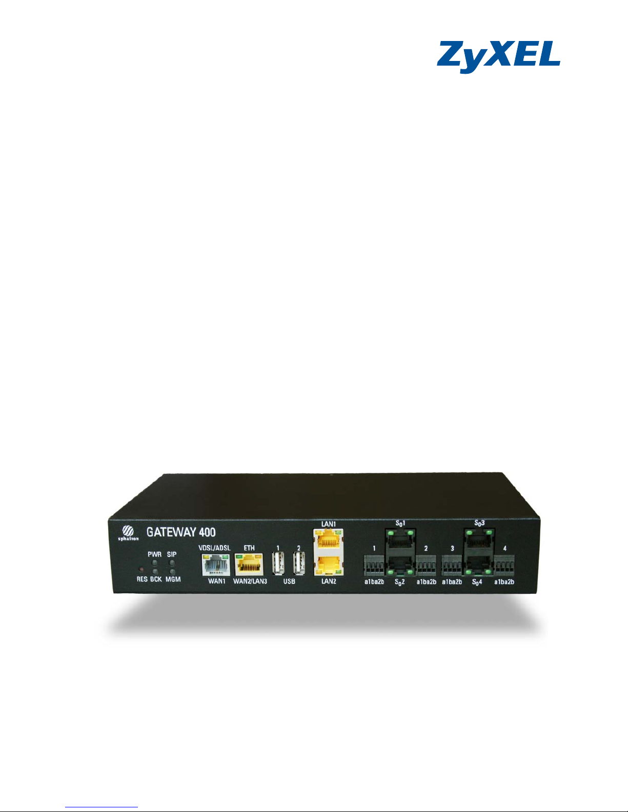
2 Your Gateway 400
2.1 Indicators and Ports on the Front Panel
Meaning of the LEDs :
Name Color Status Meaning
PWR green on/off Power is present/absent.
flashing Automatic detection of WAN interface.
red on Power-up procedure; the Gateway 400 is starting
up. The Gateway 400 will be operational after
approx. 1 minute.
flashing Software is being updated.
SIP green on/off SIP account is successfully registered/not
registered.
flashing slowly SIP account is being registered.
flashing
quickly (4 Hz)
Active ongoing call.
red flashing At least one SIP account registration has failed.
BCK Currently without function.
RJ45 sockets or clamps for connecting a telephone system or ISDN
telephones
RJ45 sockets for network devices
(e.g., computers)
USB host for USB devices
RJ45 socket for WANoE connection
or third network device.
RJ45 socket for DSL connection
LED indicators
Reset switch

Your Gateway 400 | Gateway 400 User Guide
13
MGM green on/off Internet connection established.
/No Internet connection established.
flashing Internet data traffic.
red flashing An error occurred.
VDSL/ADSL
WAN1
green on ADSL connection is active.
flashing Training on xDSL connection.
green and
yellow
on VDSL connection is active.
off xDSL connection is not active.
ETH
WAN2/L AN3
green on/off 100 MB network connection is active.
/No network device connected.
flashing Data traffic via the WAN/LAN interface.
yellow on/off 1 GB network connection is active.
/No network device connected.
LAN 1-2 green on/off 100 MB network connection is active.
/No network device connected.
flashing Data traffic on the LAN interface.
yellow on/off 1 GB network connection is active.
/No network device connected.
S0 1-4 left green on/off Bearer channel B1 is occupied/not occupied.
right green on/off Bearer channel B2 is occupied/not occupied.
Meaning of the LEDs (Contd.):
Name Color Status Meaning
Gateway 400 User Guide | Your Gateway 400
14
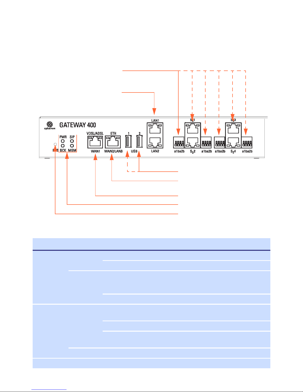
2.2 Indicators and Connectors on the Rear Panel
2.3 Reset Switch
The reset switch is located to the left of the LED indicators (and labeled RES). Use a ballpoint pen or
something similar to press the reset switch.
Be aware that pressing the reset button for different amounts of time initiates different reset actions as described below:
0.5 s - 5 s Restart with existing configuration
see Restarting the Gateway 400 on page 15
5 s - 15 s Restore factory defaults
see Resetting the Gateway 400 to the Factory Default Settings on page 15
> 15 s Additional reset actions (only if requested by customer support)
Meaning of the LEDs :
Name Color Status Meaning
Master green on Gateway 400 is in the master mode.
Slave yellow on Gateway 400 is in the slave mode.
Note
To avoid damaging the device, press the reset switch lightly, i.e., without applying any
force.
Note
Restarting and Resetting the device will cause all ongoing telephone and Internet connections to be interrupted.
Internal frame clock
LED indicator for operating mode when
cascading
Internal data clock
Connector for power cable
Power switch

Your Gateway 400 | Gateway 400 User Guide
15
2.3.1 Restarting the Gateway 400
Restarting the Gateway 400 will not affect the existing settings and configurations.
Press the reset switch (RES) for a short time (approx. 2 seconds). After about 10 seconds, the Power
LED lights up red for about 30 seconds. It then turns green again. After about 2 minutes, the Gateway 400 will be operational again.
2.3.2 Resetting the Gateway 400 to the Factory Default Settings
If you want to completely reconfigure the Gateway 400, or if the owner of the Gateway 400 chang-
es, you can delete all the settings made by restoring the factory default settings.
Proceed as follows to reset the Gateway 400 to the factory default settings:
1. Press the reset button for about 10 seconds until the Power LED turns red and flashes.
2. Then release the reset switch.
The Power LED lights up red for about 30 seconds. It then turns green again.
After about 2 minutes, the Gateway 400 will be operational again.
3. As described in Chapter 4, Setup, on page 20, you must now set up and reconfigure the Gateway 400 or load the previously saved configuration (Chapter 5.8.5, Save Configuration, on page
42) or configure Internet access using the automatic Carrier Detection (Chapter 4.2, Carrier
Detection, on page 20).
Attention
If you press the reset switch for too long, other reset actions will be initiated, which
could also result in the permanent deletion of important data. See "Reset Switch" on
page 14.
Attention
Resetting the device to the factory default settings will cause all custom settings to be
lost. You should therefore save your configuration (as described in Chapter 5.8.5, Save
Configuration, on page 42) before resetting the device.

Gateway 400 User Guide | Installation
16
3 Installation
Step 1 Connect the Gateway 400 to the mains.
Plug the supplied power cable into the connector on the rear panel of the Gateway 400 and insert
the plug into a 230V outlet. Turn on the gateway by pressing the rocker switch next to the power
cable connector.
The PWR LED starts flashing, first in red and then in green. The Gateway 400 will be operational after
approx. 2 minutes.
Step 2 Network access.
Option 1: DSL connection.
Take the gray DSL connection cable (TAE on RJ45) and plug the RJ45 connector into the VDSL/
ADSL socket of the Gateway 400. Plug the TAE connector into the TAE socket.
Option 2: WANoE connection.
Connect the modem according to the manufacturer’s instructions. Take a network cable (modem accessory) and plug the RJ45 connector into the LAN socket on the modem and the other
RJ45 connector into the ETH socket on the Gateway 400.
Step 3 Network device connection.
Take the yellow cable (network cable) and plug the RJ45 connector of the yellow cable into the LAN
1 or LAN 2 socket on the Gateway 400. Plug the other RJ45 connector into the corresponding socket
on the network device to be connected. Wait until the LAN LED begins to light up in green.
Note
The synchronization process between the Gateway 400 and the DSL network may take
several minutes to complete. After successful synchronization, the appropriate VDSL or
ADSL LED will light up. If the synchronization process fails to complete after about 10
minutes, contact the customer service of your Internet service provider (ISP).
Note
The individual LAN sockets use the following network addresses:
192.168.100.2 to 192.168.100.254 for network devices connected to the LAN 1 socket.
192.168.200.2 to 192.168.200.254 for network devices connected to the LAN 2 socket.
Installation | Gateway 400 User Guide
17
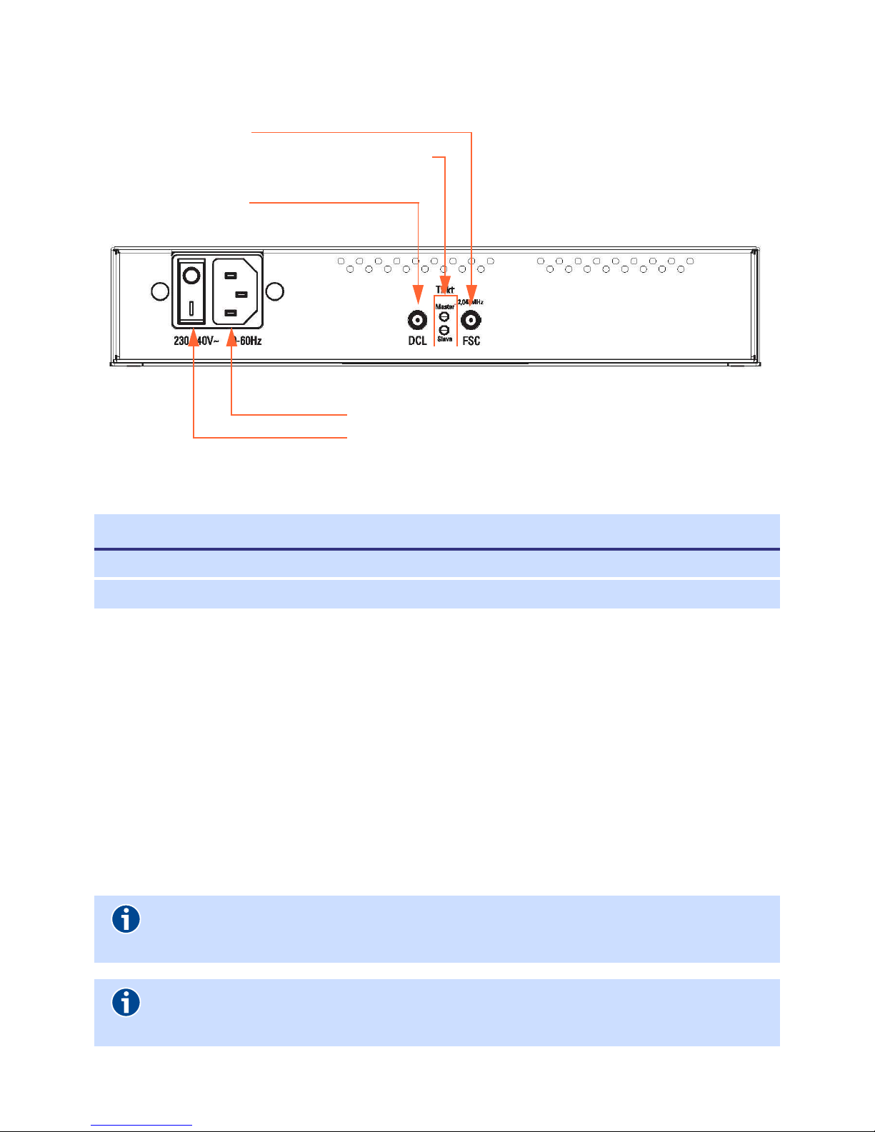
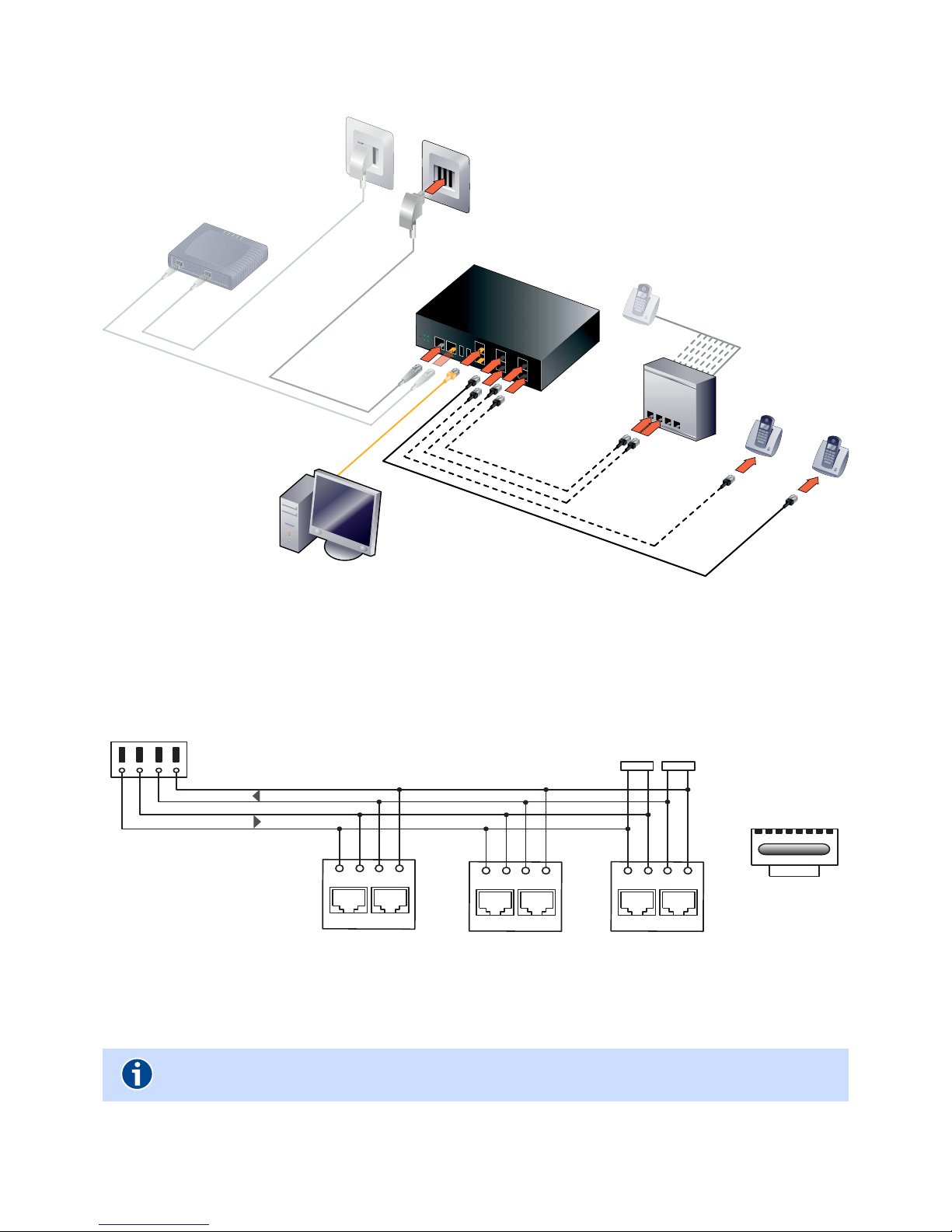
Step 4 Connection of telephone system or telephones.
The following figures illustrate the various configuration scenarios for the S0 ports on the Gateway
400 depending on the telephony hardware used:
Only point-to-point connection
Only point-to-multipoint connection
Mixed operation of point-to-point and point-to-multipoint connections
Connect your telephone system or telephones to the sockets S
0
1 to S04 or the clamps 1 to 4 (a1b
a2b). See "Installation diagram for S0 bus" on page 18.
Figure 1 Installation diagram for a point-to-point connection
Note
The ISDN interfaces of the Gateway 400 support the Restricted Power Mode.
This may reduce the functionality of ISDN telephones (e.g., no permanent display) or
cause some telephones to not behave as expected (e.g., signaling of all incoming calls,
regardless of the configured MSN). If necessary, connect an ISDN bus power supply.
PAB X
GATEWAY 400
Option 1
Option 2
Gateway 400 User Guide | Installation
18
Figure 2 Installation diagram for mixed operation of point-to-point and point-to-multipoint connections
3.1 Installation diagram for S0 bus
Figure 3 Ins ta l l at ion di a gram for S0 bus
Note
In the Gateway 400, the terminating resistors are already integrated.
PAB X
GATEWAY
400
Option 1
Option 2
ISDN Phones
1 2 3 4 5 6 7 8
RJ45 connector
cable side
Pin 3 RX+ 2a
Pin 4 TX+ 1a
Pin 5 TX- 1b
Pin 6 RX- 2b
1a 1b 2a 2b
IAE socket
1a 1b 2a 2b
IAE socket
a1b a2b
resistors
100Ω 100Ω
Gateway 400
S
0
bus
Terminating
1a 1b 2a 2b
IAE socket

Installation | Gateway 400 User Guide
19
Use the Te lephony | ISDN menu item (Page 29) to set the Bus mode according to the following criteria:
Bus mode
Short passive bus Distance between terminal devices and Gateway 400: max. 200 meters.
Max. 12 sockets and 8 terminal devices. Used only in point-to-multipoint
mode.
Extended passive bus Distance between terminal device and Gateway 400: max. 1000 meters.
Only one terminal device can be connected (point-to-point connection).
Used in point-to-point or point-to-multipoint mode; in special cases, with
only one terminal (default).
This setting is also used for the “extended passive bus”. The extended passive bus is at least 100 meters and no more than 500 meters long. The terminal devices may only be connected to the final 50 meters of the bus.
Max. 12 sockets and 4 terminal devices. Used in point-to-multipoint mode.

Gateway 400 User Guide | Setup
20
4Setup
4.1 Computer Settings
Check the LAN settings of your computer to automatically connect your computer to the Gateway
400 via the network connection using DHCP. Please refer to Chapter 1.4, page 10.
4.2 Carrier Detection
You can use the Automatic area configuration for the initial startup of the Gateway 400; it is initi-
ated automatically immediately after switching on the Gateway 400. The message “The carrier de-
tection is in process“ will appear in the Overview screen dialog of the Gateway 400. This indicates
that your Internet connection is being configured automatically and should be available after a
maximum of 5 minutes. Alternatively, the Gateway 400 can also be preconfigured individually by
the ISP (depending on the procurement source).
Carrier detection can also be started manually. In this case, you can use any computer with a current
web browser:
1. Connect the computer to the LAN 1 socket on the Gateway 400.
2. Start your web browser and enter http://sphairon.box in the address line.
You can also enter
http://192.168.100.1 for a network connection via the LAN 1 socket, or http://192.168.200.1
for a network connection via the LAN 2 socket.
3. You are now prompted to enter the access credentials. The factory defaults are as follows:
Access name: admin
Password: admin
4. The start screen dialog of the Gateway 400 user interface is displayed.
Click on the System | Protocol Stack menu item
5. In the Protocol Stack screen dialog, click the Carrier Detection button.
Note
You can cancel the Automatic carrier detection via the Overview menu item.
Note
It is recommended to first configure the network settings (Chapter 5.8.1, Protocol Stack,
on page 39) and then the device services to avoid duplicating the configuration effort.
Configuration | Gateway 400 User Guide
21
5 Configuration
You an use any computer with a current web browser (such as Mozilla Firefox, Microsoft Internet
Explorer, Google Chrome) to configure the Gateway 400.
Start your web browser and enter http://sphairon.box in the address line.
For network connections via
the LAN 1 socket, you can also use the address http://192.168.100.1 , or
for connections via the LAN 2 socket, you can use the address http://192.168.200.1.
You are now prompted to specify your access credentials. The access credentials for the default administrator are as follows:
Access name: admin
Password: admin
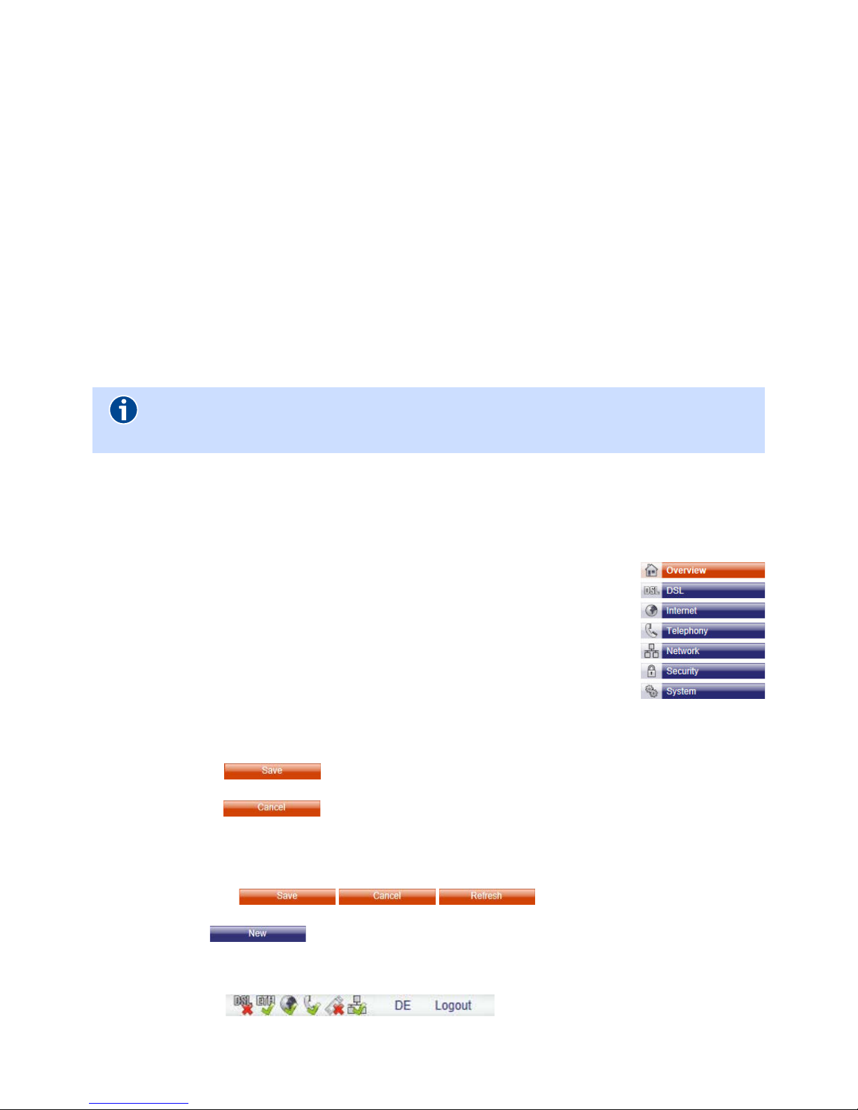
5.1 Screen Dialog Layout
Menu
The individual menu items open screen dialogs, which allow you to change
the Gateway 400 settings. The menu items are grouped by function and
may be subdivided into submenus. Chapter 5, Configuration, on page 21 describes each menu item of the Gateway 400 in detail.
Screen Dialog with Settings
Clicking on a menu item opens the corresponding screen dialog. Each screen offers various dialog boxes with settings for configuring the Gateway 400.
Clicking on the button saves the settings on the Gateway 400 and causes the
changes to take effect.
Clicking on the button opens the previous screen dialog without saving the
changes.
Buttons
Orange buttons ( ) are used to control an open
screen dialog.
Blue buttons open a new screen dialog.
Status Line
The status line displays the following elements:
Date and time
Note
We recommend that you change these credentials after the initial startup.
Please refer to Chapter 5.8.2, Access Protection, on page 42.
 Loading...