

Zte ZXDSL 9210 Technical Manual

ZXDSL 9210 (V3.1)
Broadband Universal Access
Equipment
Technical Manual
ZTE CORPORATION

ZXDSL 9210 (V3.1) Broadband Universal Access Equipment
Technical Manual
Document version 20040803-R1.2
Product version V3.1
Copyright © ZTE Corporation
All rights reserved.
No part of this documentation may be excerpted, reproduced, translated, annotated or
duplicated, in any form or by any means without the prior written permission of ZTE
Corporation.
ZTE CORPORATION ZTE DO BRASIL LTDA
ZTE Plaza, Keji Road South, Hi-Tech
Industrial Park, Nanshan District,
Shenzhen, P.R.China
ADD: Alameda Juari 522, Tamboré,
Barueri, São Paulo, Brasil - CEP
06460-090
Tel: (+86755) 26771900 800-98309830
Tel: + 0055-11-4208 3888
Fax: (+86755) 26770801 Fax: + 0055-11-42086888
Email: support@zte.com.cn Email: support@zte.com.cn
Technical Support Website: http://support.zte.com.cn
FAX: +86-755-26770160
Suggestions and Feedback
To improve the quality of ZTE product documentation and offer better services to our customers, we hope
you can give us your suggestions and comments on our documentation and fax this form to
+86-755-26770160; or mail to “Marketing center 3
rd
floor ZTE Plaza, Keji Road South, Hi-Tech Industrial
Park, Nanshan District, Shenzhen, P. R. China”. Our postcode is 518057.
Document name ZXDSL 9210 (V3.1) Broadband Universal Access Equipment Technical Manual
Product version V3.1 Document version 20040803-R1.2
Equipment installation time
Your information
Name Company
Postcode Company address
Telephone E-mail
Presentation: How is information presented? (Introductions, procedures, illustrations, others)
Good Fair Average Poor Bad
Accessibility: Can you find the information you want? (Table of contents, Index, headings,
numbering, others)
Good Fair Average Poor Bad
Your evaluation
of this
documentation
Intelligibility: Can you understand it when you find it? (Language, vocabulary, readability, others)
Good Fair Average Poor Bad
Presentation:
Accessibility:
Your suggestions
for improvement
of this
documentation
Intelligibility:
Your other
suggestions on
ZTE product
documentation


Preface
About this Manual
ZXDSL 9210 (V3.1) Broadband Universal Access Equipment (called ZXDSL 9210 for
short) is a high-speed digital subscriber transmission line developed by ZTE based on
VDSL and ADSL. The system implements bi-directional transmission of high-speed
digital signals over a common pair of twisted telephone wires, which greatly improves
the line utilization of a PSTN.
In order for you to better understand the equipment and grasp the methods of
engineering installation, operations, and routine maintenance, we have compiled a
whole suite of user documents, including
Guide to Suite of Documents for ZXDSL 9210 (V3.1) Broadband Universal Access
Equipment
ZXDSL 9210 (V3.1) Broadband Universal Access Equipment Technical Manual
ZXDSL 9210 (V3.1) Broadband Universal Access Equipment Hardware Manual
ZXDSL 9210 (V3.1) Broadband Universal Access Equipment Installation Manual -
Hardware
ZXDSL 9210 (V3.1) Broadband Universal Access Equipment Installation Manual -
Software
ZXDSL 9210 (V3.1) Broadband Universal Access Equipment Command Manual
ZXDSL 9210 (V3.1) Broadband Universal Access Equipment Interface Manual
ZXDSL 9210 (V3.1) Broadband Universal Access Equipment Operation Manual
ZXDSL 9210 (V3.1) Broadband Universal Access Equipment Maintenance Manual
How to use this Manual
This ZXDSL 9210 (V3.1) Broadband Universal Access Equipment Technical Manual
introduces the composition, performance, and technical indices of the ZXDSL 9210
system, the operating principles of the system and boards, together with its network
configuration, to help the user understand and grasp the ZXDSL 9210 system
comprehensively.

This manual includes:
Chapter 1 “Elementary Knowledge” introduces briefly the basic principles of the
ADSL and VDSL, and basic equipment-related concepts.
Chapter 2 “System Structure” introduces the overall structure, operating principles, and
features of the ZXDSL 9210 system.
Chapter 3 “Technical Indices” introduces the basic indices of the ZXDSL 9210 system
and various indices of the boards.
Chapter 4 “Hardware Structure” introduces the hardware structure of the ZXDSL 9210
system, and that of boards.
Chapter 5 “System Software” introduces the software structure of the ZXDSL 9210
system and that of an embedded BAS;
Chapter 6 “Interfaces & Communication” introduces the physical interfaces of the
ZXDSL 9210 system and the protocols applicable to this system.
Chapter 7 “Service Functions” describes the service functions of the ZXDSL 9210
system.
Chapter 8 “Networking Modes and System Configuration” introduces various
networking modes of the ZXDSL 9210 system and corresponding system
configurations.
Appendix A “Terms and Definitions” gives a brief interpretation of the key terms used
in this document.
Appendix B “Applicable Standards” introduces the standards govern the ZXDSL 9210
equipment comply with.
Appendix C “Abbreviations” makes a list of abbreviations used in this document.
Appendix D “Index” presents an index for this document.
Conventions
1. Notational convention
Angular brackets “<and>” identify names of keys and buttons, and the
information typed by an operator from a terminal

Square brackets “[and]” indicate a man-machine interface, menu item, data list
or field name. The symbol “Æ” separates a multi-level menu, e.g.,
[FileÆNewÆFolder] indicates the [Folder] menu item under the [New]
submenu of the menu [File].
2. Keyboard Operation Convention
Format Description
Characters within
angular brackets
Indicate a key or button name, e.g., <Enter>, <Tab>, <Backspace>,
and <a>
<Key 1+Key 2> Press Key 1 and Key 2 at the same time.
<Key 1, Key 2> Press Key1 first. Then release Key 1 and press Key 2
3. Mouse Operation Convention
Format Description
Click
Refers to clicking the primary mouse button (usually the left mouse
button) once
Double-click
Refers to quickly clicking the primary mouse button (usually the left
mouse button) twice
Right-click
Refers to clicking the secondary mouse button (usually the right mouse
button) once.
Drag Refers to pressing and holding a mouse button and move the mouse
4. Danger, Warning, Caution and Note Statements
Danger, Warn in g, Caution and Note statements
are used throughout this manual to emphasize important and critical information.
You must read these statements to help ensure safety and to prevent product
damage. The statements are defined below.
Danger:
Indicates an imminently hazardous situation which, if not avoided, will result in death
or serious injury. This signal word is to be limited to the most extreme situations.
Warning:
Indicates a potentially hazardous situation which, if not avoided, could result in death
or serious injury.
Caution:
Indicates a potentially hazardous situation which, if not avoided, could result in minor
or moderate injury. It may also be used to alert against unsafe practices.
Note:
A Note statement is used to notify people of installation, operation, or maintenance
information that is important, but not hazard-related.
Tips:
Indicates a suggestion or hint to make things easier or more productive for the reader
Statement: The actual product may differ from what is described in this
manual due to frequent update of ZTE products and fast development of
technologies. Please contact the local ZTE office for the latest updating
information of the product.

-i-
Contents
1 Elementary Knowledge...........................................................................................................................1-1
1.1 Overview........................................................................................................................................1-1
1.2 Fundamental Principles of DSL .....................................................................................................1-4
1.2.1 Fundamental Principles of VDSL .......................................................................................1-4
1.2.2 Basic Principles of ADSL ...................................................................................................1-5
1.3 Related Basic Concepts.................................................................................................................. 1-7
1.3.1 ATM Technology.................................................................................................................1-7
1.3.2 ADSL Access Mode ............................................................................................................1-9
1.3.3 VDSL Access Mode ..........................................................................................................1-10
2 System Structure .....................................................................................................................................2-1
2.1 Brief Introduction to the System .................................................................................................... 2-1
2.1.1 Background .........................................................................................................................2-1
2.1.2 Applicable Standards...........................................................................................................2-2
2.1.3 Functions.............................................................................................................................2-3
2.2 System Features .............................................................................................................................2-9
3 Technical Indices .....................................................................................................................................3-1
3.1 System Indices ...............................................................................................................................3-1
3.1.1 Physical Performance.......................................................................................................... 3-1
3.1.2 Power Supply of Equipment ...............................................................................................3-2
3.1.3 Environment Conditions .....................................................................................................3-3
3.1.4 Interface Indices.................................................................................................................. 3-4
3.1.5 Capacity Indices................................................................................................................ 3-16
3.2 Board Indices ...............................................................................................................................3-16

-ii-
3.2.1 SCBF ................................................................................................................................ 3-16
3.2.2 VTIEF............................................................................................................................... 3-17
3.2.3 ATIGN .............................................................................................................................. 3-17
3.2.4 Splitter Board.................................................................................................................... 3-18
3.2.5 EICM ................................................................................................................................ 3-18
3.2.6 FEC................................................................................................................................... 3-19
3.2.7 Enhanced Ethernet Subboard (FNC card)......................................................................... 3-20
3.2.8 EICG................................................................................................................................. 3-20
3.2.9 Line Protection & Control Board (LTC) ........................................................................... 3-21
3.2.10 Embedded BAS (RPCK) ................................................................................................ 3-21
3.2.11 Backplane (MDSLA)...................................................................................................... 3-21
4 Hardware Structure................................................................................................................................ 4-1
4.1 Overall Architecture of the System................................................................................................ 4-1
4.1.1 Cabinet................................................................................................................................ 4-3
4.1.2 Frame .................................................................................................................................. 4-5
4.1.3 Single-frame Configuration ................................................................................................4-5
4.1.4 Arrangement Diagram of Integrated Equipment................................................................. 4-6
4.2 Introduction to Boards ................................................................................................................... 4-8
4.2.1 SCBF .................................................................................................................................. 4-8
4.2.2 VTIEF............................................................................................................................... 4-10
4.2.3 ATIGN .............................................................................................................................. 4-12
4.2.4 VDSL Splitter Board (VSEN/VSET)................................................................................ 4-14
4.2.5 PSUN/PSUT ..................................................................................................................... 4-15
4.2.6 EICM ................................................................................................................................ 4-16
4.2.7 EICG................................................................................................................................. 4-18
4.2.8 LTC................................................................................................................................... 4-20

-iii-
4.2.9 Embedded BAS (RPCK)................................................................................................... 4-21
4.2.10 Backplane (MDSLA) ......................................................................................................4-22
5 System Software ...................................................................................................................................... 5-1
5.1 Overview........................................................................................................................................5-1
5.2 Software Environment Requirements ............................................................................................5-1
5.3 ZXDSL 9210 System Software...................................................................................................... 5-2
5.4 ZXDSL 9210 System Software Subsystem....................................................................................5-4
5.4.1 Network Management Subsystem.......................................................................................5-4
5.4.2 Subscriber Management Subsystem....................................................................................5-5
5.4.3 System Control Subsystem .................................................................................................5-6
5.4.4 Database Subsystem.......................................................................................................... 5-10
5.4.5 L3/4 Protocol Subsystem ..................................................................................................5-10
5.4.6 L2 Protocol Subsystem .....................................................................................................5-11
5.4.7 Service Control Subsystem ...............................................................................................5-13
5.4.8 Bearer Subsystem.............................................................................................................. 5-15
5.4.9 Operation Support Subsystem...........................................................................................5-15
5.4.10 BSP Subsystem ...............................................................................................................5-15
5.5 System Software of Embedded BAS ...........................................................................................5-16
5.6 System Software Subsystem of Embedded BAS ......................................................................... 5-17
5.6.1 Service Subsystem ............................................................................................................5-17
5.6.2 Bearer Subsystem.............................................................................................................. 5-20
5.6.3 Operation & Maintenance Subsystem............................................................................... 5-21
5.6.4 System Control Subsystem ...............................................................................................5-23
5.6.5 Database Subsystem.......................................................................................................... 5-24
5.6.6 Service Control Subsystem ...............................................................................................5-25
5.6.7 Operation Support Platform ..............................................................................................5-26

-iv-
5.7 Introduction to Basic BAS Concepts........................................................................................... 5-26
5.7.1 Multiple Contexts ............................................................................................................. 5-26
5.7.2 Interfaces........................................................................................................................... 5-28
5.7.3 Subscribers........................................................................................................................ 5-28
5.7.4 Ports and Circuits.............................................................................................................. 5-28
5.7.5 Bindings............................................................................................................................ 5-29
6 Interfaces and Communication ............................................................................................................. 6-1
6.1 Interfaces ....................................................................................................................................... 6-1
6.1.1 Ethernet Interface................................................................................................................ 6-1
6.1.2 User Interface...................................................................................................................... 6-4
6.2 Introduction to Protocols ............................................................................................................... 6-6
6.2.1 RFC1483 Protocol .............................................................................................................. 6-6
6.2.2 RFC1483 Bridging Protocol ............................................................................................... 6-7
6.2.3 PPP...................................................................................................................................... 6-7
6.2.4 PPPoE Protocol................................................................................................................. 6-11
6.2.5 VLAN Protocol................................................................................................................. 6-14
6.2.6 STP ................................................................................................................................... 6-17
6.2.7 RADIUS Protocol............................................................................................................. 6-17
6.2.8 802.1X Protocol................................................................................................................ 6-20
6.2.9 Multicast ........................................................................................................................... 6-25
6.2.10 VBAS Protocol ............................................................................................................... 6-29
7 Service Functions.................................................................................................................................... 7-1
7.1 Overview ....................................................................................................................................... 7-1
7.2 Introduction to Services Functions ................................................................................................ 7-1
7.2.1 Basic Service Functions...................................................................................................... 7-1
7.2.2 Broadband O&M Functions................................................................................................ 7-4

-v-
8 Networking Modes and System Configuration ....................................................................................8-1
8.1 Networking Mode ..........................................................................................................................8-1
8.1.1 Uplink Router...................................................................................................................... 8-1
8.1.2 Uplink BAS Equipment ......................................................................................................8-3
8.1.3 Convergence of Multiple 9210 Devices..............................................................................8-4
8.1.4 Chain Networking with Multiple 9210 Devices..................................................................8-5
8.1.5 Star Networking with Multiple 9210 Devices.....................................................................8-6
8.2 System Configuration.....................................................................................................................8-7
8.3 Examples........................................................................................................................................8-9
8.3.1 Networking Analysis........................................................................................................... 8-9
8.3.2 Configuration Implementation ............................................................................................ 8-9
8.3.3 Application Features..........................................................................................................8-10
Appendix A Terms and Definitions .......................................................................................................... A-1
A.1 Asymmetric Digital Subscriber Line (ADSL).............................................................................. A-1
A.2 Access Network (AN) .................................................................................................................. A-1
A.3 Asynchronous Transfer Mode (ATM) ..........................................................................................A-1
A.4 ADSL Transceiver Unit (ATU)..................................................................................................... A-1
A.5 ADSL Transceiver Unit, Central Office End (ATUC).................................................................. A-2
A.6 ADSL Transceiver Unit, Remote End (ATUR) ............................................................................A-2
A.7 Discrete Multi-Tone (DMT)......................................................................................................... A-2
A.8 Digital Subscriber Line Access Multiplexer (DSLAM)............................................................... A-2
A.9 Integrated Service Digital Network (ISDN)................................................................................. A-2
A.10 Media Access Control (MAC)....................................................................................................A-3
A.11 Management Information Base (MIB) .......................................................................................A-3
A.12 Network-Network Interface (NNI)............................................................................................. A-3
A.13 Power Spectral Density (PSD) ...................................................................................................A-3

-vi-
A.14 Quadrature Amplitude Modulation (QAM) ............................................................................... A-3
A.15 Very high-speed Digital Subscriber Line (VDSL) .................................................................... A-4
A.16 Video on Demand (VOD).......................................................................................................... A-4
Appendix B Applicable Standards ...........................................................................................................B-1
B.1 ADSL Standards............................................................................................................................B-1
B.2 ATM-Related Standards ................................................................................................................B-1
B.3 Ethernet/L2/L3 Related Standards................................................................................................B-2
B.4 National Standards........................................................................................................................B-4
Appendix C Abbreviations....................................................................................................................... C-1
Appendix D Index..................................................................................................................................... D-1

-i-
List of Figures
Fig. 1.2-1 VDSL Communication Duct ............................................................................................1-4
Fig. 1.2-2 Allocation of VDSL Channel Frequency..........................................................................1-5
Fig. 1.2-3 ADSL Communication Duct ............................................................................................1-5
Fig. 1.2-4 Allocation of ADSL Channel Frequency.......................................................................... 1-6
Fig. 1.3-1 ATM Cell..........................................................................................................................1-7
Fig. 1.3-2 Relationship between VP and VC.....................................................................................1-8
Fig. 2.1-1 Networking Diagram of ZXDSL 9210 ............................................................................. 2-2
Fig. 3.1-1 PSD of ADSL over POTS Interface .................................................................................3-4
Fig. 3.1-2 RL Indices of Z Interface.................................................................................................. 3-6
Fig. 4.1-1 Overall Hardware Architecture of the System.................................................................. 4-1
Fig. 4.1-2 Size of the DSL Cabinet (Depth: 800).............................................................................. 4-3
Fig. 4.1-3 Size of the DSL Cabinet (Depth: 600).............................................................................. 4-4
Fig. 4.1-4 ZXDSL 9210 Frame .........................................................................................................4-5
Fig. 4.1-5 Board Configuration of Single Frame ..............................................................................4-6
Fig. 4.1-6 Configuration of the Integrated Equipment (DSL cabinet (Depth: 800))......................... 4-7
Fig. 4.2-1 Operating Principles of SCBF ..........................................................................................4-9
Fig. 4.2-2 Operating Principles of VTIEF.......................................................................................4-11
Fig. 4.2-3 Operating Principles of ATIGN ......................................................................................4-13
Fig. 4.2-4 Operating Principles of VSEN........................................................................................4-14
Fig. 4.2-5 Operating Principles of VSET........................................................................................4-15
Fig. 4.2-6 Operating Principles of PSUN........................................................................................ 4-16
Fig. 4.2-7 Operating Principles of PSUT ........................................................................................4-16
Fig. 4.2-8 Operating Principles of Ethernet Interface Subcards......................................................4-17

Fig. 4.2-9 Operating Principles of EICG ........................................................................................ 4-19
Fig. 4.2-10 Operating Principles of LTC ........................................................................................ 4-20
Fig. 4.2-11 Operating Principles of RPCK ..................................................................................... 4-21
Fig. 5.3-1 Overall Block Diagram of ZXDSL 9210 System Software ............................................. 5-2
Fig. 5.5-1 Overall Block Diagram of Embedded BAS System Software ....................................... 5-16
Fig. 5.6-1 Structure of Bearer Subsystem....................................................................................... 5-20
Fig. 5.6-2 Structure of Control Subsystem ..................................................................................... 5-23
Fig. 5.6-3 Relationship between Data Subsystems......................................................................... 5-24
Fig. 6.1-1 Schematic Diagram of Uplink Networking of Ethernet Interface (Adopting embedded
BAS) .................................................................................................................................................... 6-2
Fig. 6.1-2 Schematic Diagram of Uplink Networking of Ethernet Interface (Adopting distributed
BAS equipment) .................................................................................................................................. 6-2
Fig. 6.1-3 Relationship between Operation Modes of ZXDSL 9210................................................ 6-6
Fig. 6.2-1 Protocol Stack of RFC1483 Bridged................................................................................ 6-7
Fig. 6.2-2 Status Flow of PPP........................................................................................................... 6-8
Fig. 6.2-3 PPP Encapsulation Format ............................................................................................. 6-11
Fig. 6.2-4 PPPoE Protocol over Ethernet ....................................................................................... 6-12
Fig. 6.2-5 Communication Flow of PPPoE .................................................................................... 6-12
Fig. 6.2-6 Stages Involved in PPPoE Data Encapsulation.............................................................. 6-14
Fig. 6.2-7 Format of Tag Header .................................................................................................... 6-16
Fig. 6.2-8 Communication Flow of Access Authentication and Authorization with One or Multiple
RADIUS Servers ............................................................................................................................... 6-18
Fig. 6.2-9 Session Flow of Authentication Switching Among the Supplicant, Authenticator, and
Authentication Server ........................................................................................................................ 6-23
Fig. 6.2-10 EAPOL Frame Format of 802.1 Ethernet..................................................................... 6-24
Fig. 6.2-11 Format of EAP Packet.................................................................................................. 6-24
Fig. 6.2-12 PPP Authentication when VBAS Process is Added ..................................................... 6-31

iii
Fig. 7.2-1 High-speed Internet Access (Adopting distributed BAS equipment)............................... 7-2
Fig. 7.2-2 High-speed Internet Access (Adopting embedded BAS) .................................................7-2
Fig. 7.2-3 VOD (Take for example the case when an embedded BAS is installed)..........................7-3
Fig. 7.2-4 Remote Enterprise LAN Access....................................................................................... 7-4
Fig. 8.1-1 Schematic Diagram of Uplink Router Networking (ADSL and VDSL user access)........8-2
Fig. 8.1-2 Schematic Diagram of Uplink Router Networking ( Ethernet user access) .....................8-2
Fig. 8.1-3 Networking Diagram of Uplink BAS Equipment.............................................................8-3
Fig. 8.1-4 Networking Diagram of Uplink BAS Equipment ( Ethernet user access)........................8-3
Fig. 8.1-5 Networking Diagram when Multiple 9210s are Converged............................................. 8-4
Fig. 8.1-6 Schematic Diagram of Chain Networking with Multiple ZXDSL 9210 Devices.............8-5
Fig. 8.1-7 Star Networking with Multiple ZXDSL 9210 Devices ....................................................8-6
Fig. 8.3-1 Actual Networking Diagram of ZXDSL 9210..................................................................8-9


-i-
List of Tables
Table 1.2-1 Transmission Rates of High-Speed Uplink/Downlink Channels ...................................1-4
Table 1.2-2 Transmission Rates of High-Speed Channels and Medium-Speed Channels ................ 1-6
Table 3.1-1 Power Consumption Indices of Boards.......................................................................... 3-2
Table 3.1-2 PSD of ADSL over POTS ..............................................................................................3-5
Table 3.1-3 Parameters of 100M Ethernet Multimode Optical Interface (Transmitting)................3-10
Table 3.1-4 Parameters of the 100M Ethernet Multimode Optical Interface (Receiving) ..............3-11
Table 3.1-5 Parameters of 100M Ethernet Single-Mode Optical Interface (Transmitting)............. 3-11
Table 3.1-6 Parameters of the 100M Ethernet Single-Mode Optical Interface (Receiving) ...........3-12
Table 3.1-7 Parameters of the 1000M Multimode Optical Transmitter ..........................................3-13
Table 3.1-8 Parameters of the 1000M Multimode Optical Receiver...............................................3-14
Table 3.1-9 Parameters of the 1000M Single-Mode Optical Transmitter .......................................3-15
Table 3.1-10 Parameters of 1000M Single-Mode Optical Receiver ...............................................3-15
Table 8.3-1 User’s Hardware Configuration of ZXDSL 9210 .......................................................... 8-9
Table B.1-1 ADSL Standards........................................................................................................... B-1
Table B.2-1 ATM-Related Standards ............................................................................................... B-1
Table B.3-1 Ethernet/L2/L3 Related Standards................................................................................ B-2
Table B.4-1 National Standards ....................................................................................................... B-4


1-1
1 Elementary Knowledge
As the basis for subsequent chapters, this chapter introduces the elementary knowledge
of VDSL and ADSL, including the basic principles of VDSL and ADSL, ATM
technology and ADSL, together with common access modes of VDSL.
1.1 Overview
With rapid development of Internet and gradual finalization of backbone access layer
networks, the so-called user-oriented “last mile” access has become more and more
important. To adapt to new trends and meet new demands, multiple broadband access
technologies have emerged. In terms of transmission media, there are multiple wired
access technologies, such as copper wire access technology, fiber access technology,
and Hybrid Fiber Coaxial (HFC) access technology, and wireless access technologies.
The copper wire access technology, applied most widely, includes two wiring modes.
One is to lay Category 5 twisted pairs and establish a switching Ethernet; the other is to
fully employ precious resources of the original copper wires (telephone subscriber
lines), and adopt various technologies of high-speed modulation and coding for
broadband access. The popular copper wire technologies at present are described as
follows.
1. LAN access technology
The transmission media of Ethernet/fast Ethernet include twisted pairs, coaxial
cables or fibers. At present, twisted pair networks with the optimal
cost-performance ratio have been widely applied. The Ethernet technology
transmits directly baseband digital signals over transmission media, for example,
up to a 100-meter transmission distance over Category 5 cables. Its
disadvantages include short transmission distance, excessively scattered
equipment, high-cost initial investment, inconvenient management, and
necessary cable redistribution.

ZXDSL 9210 (V3.1) Broadband Universal Access Equipment Technical Manual
1-2
2. High-speed Digital Subscriber Line (HDSL) technology
HDSL adopts the coding type 2B1Q code or CAP code. Two pairs of subscriber
lines among existing telephone lines can be used to provide full-duplex T1/E1
signal transmission. For common subscriber lines with a line width of 0.4 mm to
0.6 mm, the transmission distance amounts to 3 km to 6 km. If the line width is
greater, the transmission distance may amount to 10 km. Furthermore, there is
currently a kind of HDSL product transmitting T1/E1 signals over a twisted pair
and it is normally called Single Digital Subscriber Line (SDSL). The
HDSL/SDSL technology has been widely used in access to TDM telecom
networks and also in the broadband Internet access of enterprises. It features
bi-directional symmetry and high rate while its disadvantages include lack of
universal standards and high costs.
3. Asymmetric Digital Subscriber Line (ADSL) technology
ADSL is an asymmetrical broadband access mode, that is, the uplink rate of
subscriber lines is different from the downlink rate. According to the
characteristics of various multimedia services subscribers use, the uplink rate is
lower while the downlink rate is higher, thus especially applicable to
retrieval-type network services. A typical uplink rate of ADSL is 64 kbps to 1
Mbps, and its typical downlink rate is 1.544 Mbps to 8.192 Mbps. The greatest
transmission distance is 5 km. The ADSL broadband access and ordinary
telephone services may share the same subscriber line. In practice, ADSL
involves line selection ratio, generally about 10%. In addition, the rate of ADSL
is in inverse proportion to line length. Because of many limiting factors, the
actual service rates of ADSL are about 512 kbps to 3 Mbps for downlink
transmission, and about 64 kbps for uplink transmission. Therefore, the
advantages of ADSL are that it fully employs existing copper wire resources,
and shares copper wires with ordinary telephone services; its disadvantages lie
in line selection ratio and low bandwidth rate.
4. Very High-speed Digital Subscriber Line (VDSL) technology
VDSL is a new-type broadband copper wire access technology. It adopts the
Ethernet over VDSL technology and integrates the VDSL technology with the
Ethernet technology. The VDSL access technology uses QAM or DMT
modulation. When the line width is 0.4mm and the transmission distance is 1 km,

Chapter Erro! Estilo não definido. Erro! Estilo não definido.
1-3
the bi-directional transmission rate of the VDSL can reach 10 Mbps. There may
be greater coverage when the line width becomes larger. Just like ADSL, VDSL
may share the same subscriber line with ordinary telephone services. Because of
small distance, the VDSL technology overcomes some ADSL problems such as
low line selection ratio and unstable rate.
As a trend of the ADSL technology, VDSL is the most advanced digital
subscriber line technology at present. The VDSL technology transmits signals
over a pair of twisted copper wires. With the frequency-division multiplexing
technology, the VDSL technology transmits uplink/downlink signals of
telephone and VDSL within different frequency bands. Low frequency bands
transmit ordinary telephone and narrowband ISDN services; medium frequency
bands transmit images of downlink channels or high-speed data information;
high frequency bands transmit information of uplink digital channels. Different
service signals at the transmitting end are modulated into different frequency
bands and then transmitted over twisted pair cables to the receiving end, where
they are demodulated and filtered to regenerate the original signals. Therefore,
as long as you configure a VDSL Modem at the central office and one at the
subscriber premises, telephone services can be added to channels by means of
POTS splitters and couplers. And the HDTV digital images or multi-channel
code-compressed MPEG images can be transmitted to the subscriber premises
via VDSL downlink channels.
Compared with the ADSL technology, the VDSL technology features simple
network construction scheme, convenient use and high transmission rate (10
times higher than that of ADSL). The transmission distance of VDSL is slightly
smaller than that of the ADSL technology. The interference between its
transmission code elements is greatly reduced due to shortened transmission
distance. This simplifies requirements for digital signal processing and reduces
transceiver costs as compared with those in the ADSL system. In the meantime,
because of its shorter transmission distance, the VDSL technology overcomes
some ADSL problems, such as low line selection ratio and unstable rate.
By combining the VDSL and Ethernet technologies, high-speed Ethernet signals
can be transmitted over ordinary telephone lines, and users can be connected to
Internet just by means of VDSL terminal adapters without rewiring the costly
Category 5 twisted pair. The combination of the VDSL and Ethernet
ZXDSL 9210 (V3.1) Broadband Universal Access Equipment Technical Manual
1-4
technologies solves the problem of accessed subscribers’ data security and
quality of service. Besides, this solution provides operators with convenient
methods of accounting, which solve the complicated problem existing in
previous Ethernet management and accounting.
1.2 Fundamental Principles of DSL
1.2.1 Fundamental Principles of VDSL
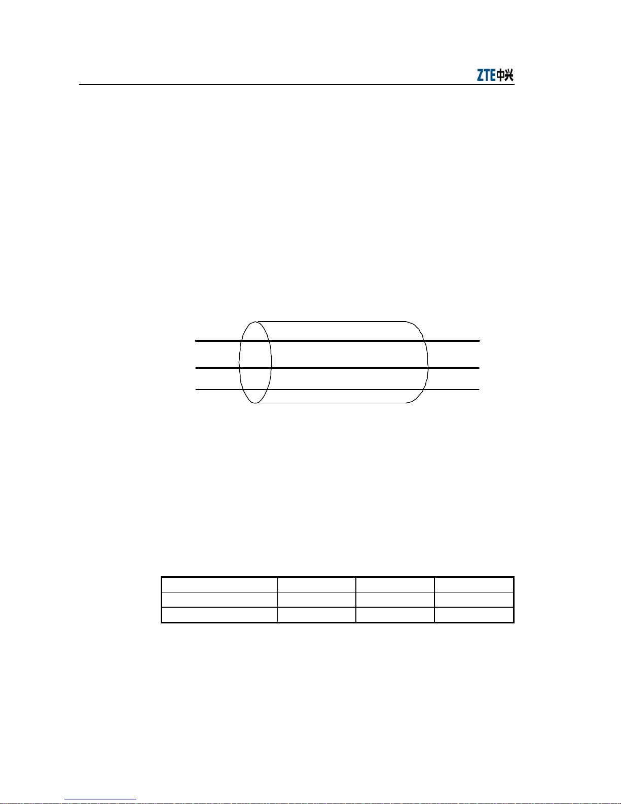
Generally, QAM is adopted by the IP-based VDSL, and connects both ends of the
existing twisted pair with its special modulation/demodulation hardware. It establishes
a 3-channel duct, as shown in Fig. 1.2-1.
Low-frequency channel
High-speed downlink channel
High-speed uplink channel
Fig. 1.2-1 VDSL Communication Duct
The duct has a high-speed uplink channel, a high-speed downlink channel (to the
subscriber premises), and a low-frequency channel (0 kHz to 900 kHz). The
low-frequency channel ensures that voice communication or ISDN runs normally even
if the VDSL connection fails. For the transmission rates of the high-speed
uplink/downlink channels, please refer to Table 1.2-1.
Table 1.2-1 Transmission Rates of High-Speed Uplink/Downlink Channels
Channel Average Rate Lowest Rate Highest Rate
High-speed downlink channel 10 Mbps 4 Mbps 16.7 Mbps
High-speed uplink channel 9.1 Mbps 1.5 Mbps 16.7 Mbps
Note: This table is for reference only. Actual rate is subject to physical cable length, dimensions, and interference.
The IP-based VDSL needs no medium access control, so each subscriber can work in
the continuous full-speed environment. The VDSL rate depends entirely on line
Chapter Erro! Estilo não definido. Erro! Estilo não definido.
1-5
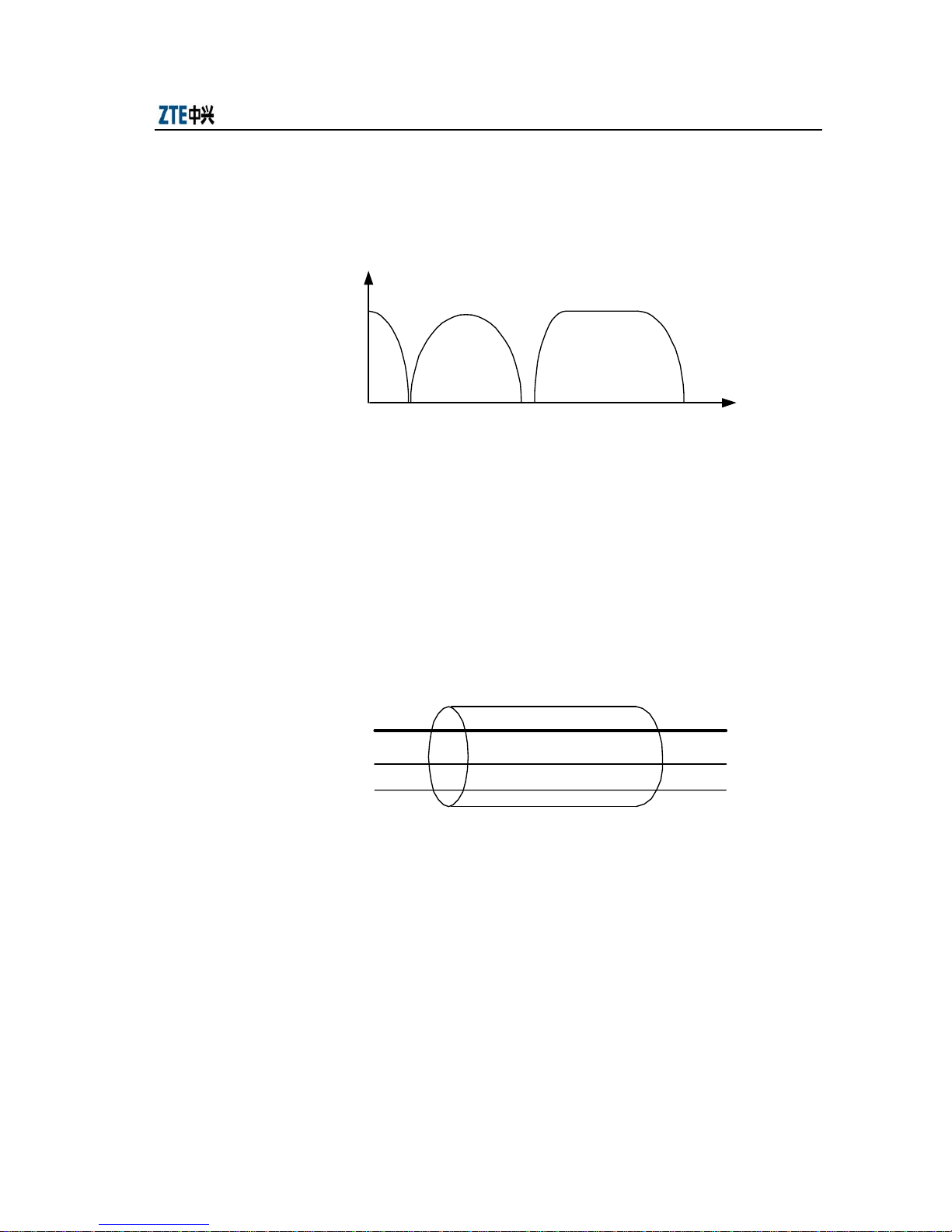
distance, that is, the longer a line is, the lower rate it has. The lowest uplink rate is 1.5
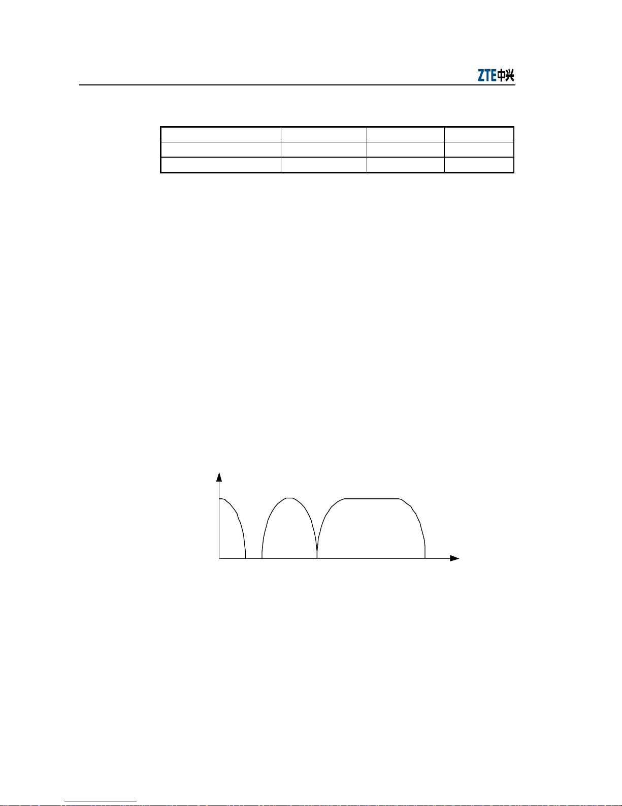
Mbps while the lowest downlink rate is 4 Mbps. Fig. 1.2-2 is the allocation of the
VDSL channel frequency.
Low-frequency
channel
Uplink
channel
Downlink channel
900kHz
3.4MHz
7.5MHz
P
(f)
4MHz
f
Fig. 1.2-2 Allocation of VDSL Channel Frequency
The downlink signals of VDSL employ the frequency bands of 900 kHz to 3.4 MHz
while its uplink signals employ those of 4 MHz to 7.5 MHz.
1.2.2 Basic Principles of ADSL
In the ADSL technology, special modulation/demodulation hardware is used to connect
the ends of existing twisted pairs, and this technology establishes a 3-channel duct, as
shown in Fig. 1.2-3.
High-speed downlink channel
Medium-speed duplex channel
POTS channel
Fig. 1.2-3 ADSL Communication Duct
This duct has a high-speed downlink channel (to the subscriber premises), a
medium-speed duplex channel, and a POTS channel (0 to 4 kHz). The POTS channel
ensures that voice communication still runs normally even if the ADSL connection fails.
Both high-speed channels and medium-speed channels can be multiplexed to create
multiple low-speed channels. Please refer to Table 1.2-2 for the transmission rates of
high-speed and medium-speed channels.
ZXDSL 9210 (V3.1) Broadband Universal Access Equipment Technical Manual
1-6
Table 1.2-2 Transmission Rates of High-Speed Channels and Medium-Speed Channels
Channel Average Rate Lowest Rate Highest Rate
High-speed downlink channel 6 Mbit/s 1.5 Mbit/s 8 Mbit/s
Medium-speed duplex channel 512 kbit/s 64 kbit/s 1 Mbit/s
Note: This table is for reference only. Actual rate is subject to the physical cable length, dimension, and interference.
In the past years, the hardware technology of the telephone system has improved a lot
while ADSL achieves a surprising rate very simply: Compression. It uses very
advanced DSP and algorithms to compress as much information as possible in the
telephone line (twisted pair). ADSL products employ FDM to multiplex
uplink/downlink channels, and isolate POTS channels. In order to fully utilize
spectrum, ADSL generally adopts the DMT modulation. DMT divides 1 MHz spectrum
into 256 sub-channels with the bandwidth of 4.3125 kHz. The number of bits over each
channel is determined by the actually measured channel quality, so as to shunt those
noisy sub-channels with too much damage, thus realizing reliable communication.
ADSL working between points needs no medium access control, so each subscriber can
work in the continuous full-speed environment. The ADSL rate depends fully on line
distance, that is, the longer a line is, the lower rate it has. The rate may be lower than
1.5 Mbit/s, but the average rate may amount to 6 Mbit/s. Fig. 1.2-4 illustrates the
allocation of the channel frequency of ADSL over POTS.
Uplink channel
POTS
4kHz 138kHz 1.104MHz30kHz
P (f)
f
Downlink channel
Fig. 1.2-4 Allocation of ADSL Channel Frequency
ZXDSL 9210 uses the Frequency-Division Multiplexing (FDM) technology, and spares
0 to 4 kHz for ordinary telephone signals by closing low-end sub-channels. The uplink
signals use the frequency bands of 30 kHz to 138 kHz while the downlink signals
occupy those of 138 kHz to 1.104 MHz.

Chapter Erro! Estilo não definido. Erro! Estilo não definido.
1-7
ZXDSL 9210 employs two kinds of channels with different delay and reliability: Fast
channels (Fastonly) and interleaved channels (Interleave). The function of the
“Fastonly” channel is to make bit stream sent at the transmitting end reach the
receiving end within the shortest period of time via this path. The necessary waiting
time is 2ms. However, data correctness is not always so important. Normally, these are
some voice packets. Therefore, conversation quality will not be affected greatly even if
some packets are lost. An interleaved channel ensures that data reach correctly the
receiving end. The ADSL access network requires that the waiting time of an
interleaved channel should be 20 ms, that is, an interleaved channel trades the waiting
time for correctness of transmitted data.
1.3 Related Basic Concepts
1.3.1 ATM Technology
When the ADSL technology is adopted, there can be cell transmission based on
Asynchronous Transfer Mode (ATM) between subscriber premises equipment and
central office equipment. Essentially, ATM is a fast packet switching mode, so it
features flexible adaptability to new services and high resource utilization. Without
link-by-link error control, but with fixed-length packet data structure, it simplifies
protocols greatly as compared with other packet switching modes. Since packets are
processed by hardware, the processing capability is enhanced and the switching delay
reduced, thus making ATM suitable for real-time services.
The ATM technology splits digital information into 53-byte units - ATM Cells, also the
basic units for ATM information transmission/switching/multiplexing. Each cell
consists of the header and payload, as shown in Fig. 1.3-1.
48 bytes
5 bytes
Cell header
Cell payload
Fig. 1.3-1 ATM Cell
The 5-byte ATM cell header is used to store the information like flow control, virtual
Circuit Identity Code (CIC), and data payload. The remaining 48 bytes are for data
payload. ATM realizes data switching by means of the virtual circuit technology, and
transmits multiple types of data, including voice, video, and data. In addition, its

ZXDSL 9210 (V3.1) Broadband Universal Access Equipment Technical Manual
1-8
waiting time is far shorter than that of IP packets since an ATM cell is only 53 bytes
long. These advantages of ATM make it an extremely popular technology in the whole
ADSL-based service network. Even American National Standard Institute (ANSI) has
listed ATM as an ADSL-supported transfer mode.
The Virtual Connection (VC) concept has been introduced into the ATM switching
technology. ATM is a connection-oriented technology different from the traditional
circuit-switching in connection. In traditional circuit switching, a connection line is
established via a call before both parties begin communication. This line has a fixed
bandwidth, and the connection will not be released until the communication is over.
ATM, on the other hand, adopts a VC connection concept: When establishing a
connection, ATM requests network of traffic description and QoS requirement.
Network pre-allocates resources for this connection alone, and network resource is
occupied only when cells are actually transmitted. This is bandwidth.
VC is a general concept and actually consists of Virtual Channel (VC) and Virtual Path
(VP). A VP provides the communication capability for transferring ATM cells between
two adjacent ATM entities and is identified with a VP Identifier (VPI). There are two
types of VPs: Permanent Virtual Circuit (PVC) and Switched Virtual Circuit (SVC).
PVC establishes a semi-permanent connection in a VP via network management, while
SVC is a connection established dynamically by means of signal processing. A VC is
composed of multiple VPs, and is identified with a VP Identifier (VPI). A group of VCs
with the same VPI form a VP. The relationship between VP and VC is described in Fig.
1.3-2.
VPi
VC1
VC2
VCn
Fig. 1.3-2 Relationship between VP and VC
VPI and VCI make sense locally only. Each VPI/VCI is processed at the corresponding
VP/VC switching node, and the same VPI/VCI value in different VP/VC link section
does not represent the same “virtual connection”.

Chapter Erro! Estilo não definido. Erro! Estilo não definido.
1-9
1.3.2 ADSL Access Mode
Depending on the way it is accessed to Internet, ADSL employs slightly different
protocols. No matter what protocol is used by ADSL, ADSL is based on the most
fundamental protocol - TCP/IP, and supports all TCP/IP program applications.
1.3.2.1 Leased Line Access
In this mode, ISP provides static IP address and host name. Since ADSL outputs LAN
signals directly, it has the same software settings as LAN, and employs TCP/IP directly.
1.3.2.2 Virtual Dial-up Mode
As its name implies, the virtual dial-up mode resembles ordinary dial-up for Internet
access. This mode is easy to use and user-friendly. It involves account authentication
and IP address allocation. However, ADSL is not connected with a specific ISP access
code (like 163 or 169), but with an ADSL VPN access server. Because of simple
installation and maintenance, the LAN virtual dial-up mode has become the
mainstream of ADSL virtual dial-up. In addition, it has an independent set of network
protocol - PPPoE for account authentication and IP allocation.
Point to Point Protocol over Ethernet (PPPoE) is made and developed to satisfy more
and more broadband online equipment (such as ADSL, wireless, and cable TV), and
the increasingly faster Internet communication. It is based on two widely accepted
standards: Ethernet and PPP. The end users do not need to know much about the LAN
technology, but only to take the ADSL access as common dial-up access. There is no
need for service providers to support the leased line mode by performing large-scale,
costly reconstruction of existing Ethernet and setting IP address to bind subscribers.
This makes PPPoE superior to other protocols in broadband access services. Therefore,
it has come to be the best choice for broadband Internet access. In essence, PPPoE is a
relay protocol between Ethernet and dial-up network. It inherits the high-speed feature
of Ethernet and the features of the PPP dial-up, such as simplicity, user authentication,
and IP address allocation.

ZXDSL 9210 (V3.1) Broadband Universal Access Equipment Technical Manual
1-10
1.3.2.3 Commonly Used PPPoE Software
PPPoE software is used to connect the PPP of the operating system with the Ethernet
protocol, and connect to the ISP via the PPPoE.
1. EnterNet
EnterNet is developed by NTS.COM (which has been merged into Efficient
Networks, one equipment development & manufacturing company). It has an
independent PPP and provides PPP independent of dial-up network of the
operating system. EnterNet connects ISP directly via a network card. As the
most popular PPPoE software, it currently supports many operating systems,
such as Windows, Linux, and MacOS. It consists of multiple series: 100, 300
(the most popular at present), and 500 according to their functions.
2. WinPoET
Developed by iVasion.com (now called WindRiver), it is one of the drafters of
PPPoE. WinPoET occupies a huge market share in PPPoE software and is used
by many superpower ISPs. WinPoET provides PPP via dial-up network of the
operating system, so the use of WinPoET for Internet access is very similar to
dial-up access via 56K MODEM. WinPoET just provides PPPoE service at the
background.
3. RASPPPoE
RASPPPoE is one PPPoE driver developed by certain individuals. Compact and
effective, its interface is just a driver. It provides PPP by using dial-up network
of the operating system. Since RASPPPoE works as one network protocol
component, it is easy to use just as an old model 56K modem.
1.3.3 VDSL Access Mode
The VDSL access mode is the same as the ADSL access mode and also consists of
leased line access and virtual dial-up access. Besides, dial-up software with the same
PPPoE can be used for virtual dial-up access. This is not detailed here.
 Loading...