

Page 1

ZXCBTS (V5.4)
CDMA Micro Base Transceiver Station
& RF Remote Station
Installation Manual
ZTE CORPORATION
Page 2

ZXCBTS (V5.4) CDMA Micro Base Transceiver Station/RF Remote
Station
Installation Manual
Manual Version 20050422-R1.1
Product Version V5.4
Copyright © 2004 ZTE Corporation
All rights reserved.
No part of this documentation may be excerpted, reproduced, translated, annotated or
duplicated, in any form or by any means without the prior written permission of ZTE
Corporation.
* * * *
ZTE CORPORATION
ZTE Plaza, Keji Road South, Hi-Tech Industrial Park, Nanshan District, Shenzhen, P.R.China
Website: http://www.zte.com.cn
Postcode: 518057
Customer Support Center: (+86755) 26771900 800-9830-9830
Fax: (+86755) 26770801
Email: support@zte.com.cn
* * * *
S.N.: sjzl20030272
Page 3
FAX:+86-755-26770160
Suggestions and Feedback
To improve the quality of ZTE product documentation and offer better services to our customers, we hope
you can give us your suggestions and comments on our documentation and fax this form to
rd
+86-755-26770160; or mail to “Marketing center 3
Park, Nanshan District, Shenzhen, P. R. China”. Our postcode is 518057.
Document name ZXCBTS (V5.4) CDMA Micro Base Transceiver Station/RF Remote Stations Installation Manual
Product version V5.4 Document version 20050422-R1.1
Equipment installation time
Your information
floor ZTE Plaza, Keji Road South, Hi-Tech Industrial
Name
Postcode
Telephone
Your evaluation
of this
documentation
Your suggestions
for improvement
of this
documentation
Presentation: How is information presented? (Introductions, procedures, illustrations, others)
F Good F Fair F Average F Poor F Bad
Accessibility: Can you find the information you want? (Table of contents, Index, headings,
numbering, others)
F Good F Fair F Average F Poor F Bad
Intelligibility: Can you understand it when you find it? (Language, vocabulary, readability, others)
F Good F Fair F Average F Poor F Bad
Presentation:
Accessibility:
Intelligibility:
Company
Company address
E-mail
Your other
suggestions on
ZTE product
documentation
Page 4

Page 5

Preface
About This Manual
This manual presents the hardware installation procedures of ZXCBTS micro base
transceiver stations (BTSs)/remote stations.
It is one of ZTE manual series for CDMA cellular mobile communications system. It
aims to providing guidance to the engineering personnel who install ZTE CDMA
micro-BTS/remote stations, as well as offering reference for the equipment
maintenance personnel.
Correct hardware installation is the basis for reliable and normal running of the base
transceiver stations, thus enjoying importance in engineering construction. To facilitate
the installation, this manual is written following the sequence of actual hardware
installation. First, it briefs the structure of the ZXCBTS products, which is helpful for
the installation personnel to get familiar with the equipment. Next, it describes the
equipment installation procedures in detail. Finally, it presents how to check the
equipment after the installation.
How to Use This Manual
1. Overview
Introduces the basic structure, basic installation procedures and points for
attention during installation of the micro-BTS/remote stations.
2. Preparations
Introduces the preparations for the installation, including listing needed tools
and checking the installation environment.
3. Open-box Inspection
Introduces the procedures and cautions for opening boxes and inspecting the
equipment.
4. Installation of Cabinet
Details the fixation and installation of the cabinet of the equipment.
5. Installation of Power Supply System
Page 6

Details the installation of the power supply system of the equipment.
6. Installation of Grounding System
Details the installation of the grounding system of the equipment.
7. Connection of Cables
Details the check of internal cable connections between various modules, as well
as type selection and connection of external cables.
8. Installation of Primary Antenna Feeder System
Details the installation of the antenna feeder system of the equipment, including
the procedures of assembling feeder cable connectors, installing antenna, laying
feeder cables, installing feeder cable window and grounding equipment.
9. Installation of GPS antenna feeder system
Details the installation of GPS antenna feeder system for the equipment,
Conventions
including the procedures of assembling feeder cable connectors and installing
antenna.
10. Installation of Internal Modules
Details the installation of internal modules.
11. Hardware Installation Check
Presents how to check the hardware installation.
12. Power-on and Power-off
Presents the procedures of powering on/off the equipment.
13. Appendix
Presents the equipment performance specifications, meaning of various
indicators and connection of cables.
1. Notational Convention
Angular brackets “< >” identify names of keys and buttons, and the information
typed by an operator from a terminal. Square brackets “[ ]” indicate a
man-machine interface, menu item, data list or field name. The symbol “→”
Page 7
separates a multi-level menu, for example, [File→New→Folder] indicates the
[Folder] menu item under the [New] submenu of the menu [File].
2. Keyboard Operation Convention
Format Description
<Key>
<Key1+Key2> Press Key 1 and Key 2 at the same time.
<key1, Key2> Press Key1 first. Then release Key 1 and press Key 2.
Indicate a key or button name, for example, <Enter>, <Tab>,
<Backspace>, and <a>.
3. Mouse Operation Convention
Format Description
Click
Double-click
Right-click
Drag Refers to pressing and holding a mouse button and move the mouse
Refers to clicking the primary mouse button (usually the left mouse
button) once
Refers to quickly clicking the primary mouse button (usually the left
mouse button) twice
Refers to clicking the secondary mouse button (usually the right mouse
button) once.
4. Danger, Warning, Caution and Note Statements
Note, Caution, War ni ng , Danger statements are
used throughout this manual to emphasize important and critical information.
You must read these statements to help ensure safety and to prevent product
damage.
Statement: The actual product may differ from what is described in this
manual due to frequent update of ZTE products and fast development of
technologies. Please contact the local ZTE office for the latest updating
information of the product.
Page 8

FCC & IC STATEMENT
Before using this CDMA Micro Base Transceiver Station & RF Remote Station, read this important RF
energy awareness and control information and operational instructions to ensure compliance with the FCC
and IC RF exposure guidelines.
NOTICE: Working with the equipment while in operation, may expose the technician to RF
electromagnetic fields that exceed FCC rules for human exposure. Visit the FCC website at
www.fcc.gov/oet/rfsafety
Changes or modifications to this unit not expressly approved by the party responsible for compliance will
void the user’s authority to operate the equipment. Any change to the equipment will void FCC and IC
grant.
This equipment has been tested and found to comply with the limits for a Class A digital device, pursuant
to the FCC and IC Rules. This equipment generates, uses and can radiate radio frequency energy and, if not
installed and used in accordance with the instructions, may cause harmful interference to radio
communications. However, there is no guarantee that interference will not occur in a particular installation.
For OUTDOOR use, a PNALE Antenna with a maximum gain of 17dBi is authorized for use with this unit.
Outside antennas must be positioned to observe minimum separation of 2M (6.56 feet.) for 800MHz unit
and 1.5M (4.92 feet.) for 1900MHz unit from all users and bystanders. For the protection of personnel
working in the vicinity of outside (uplink) antennas, the following guidelines for minimum distances
between the human body and the antenna must be observed.
to learn more about the effects of exposure to RF electromagnetic fields.
The installation of an OUTDOOR antenna must be such that, under normal conditions, all personnel cannot
come within 2M (6.56 feet) for 800MHz unit and 1.5M (4.92 feet) for 1900MHz unit from the outside
antenna. Exceeding this minimum separation will ensure that the worker or bystander does not receive
RF-exposure beyond the Maximum Permissible Exposure according to section 1.1310 i.e. limits for
Controlled Exposure.
Page 9

Contents
1 Overview..................................................................................................................................................1-1
1.1 Introduction to Micro-BTS ............................................................................................................1-1
1.2 Installation Overview.....................................................................................................................1-4
1.3 Installation Flow ............................................................................................................................1-5
1.4 Points for Attention ........................................................................................................................1-7
2 Preparations ............................................................................................................................................2-1
2.1 Installation Environment Check..................................................................................................... 2-1
2.1.1 Checking Equipment Building Conditions..........................................................................2-1
2.1.2 Checking Indoor Environment............................................................................................2-1
2.1.3 Checking Power Supply System .........................................................................................2-2
2.1.4 Checking Grounding System ..............................................................................................2-2
2.1.5 Checking Relative Devices .................................................................................................2-2
2.2 Tools and Instruments ....................................................................................................................2-2
2.3 Technical Documents ..................................................................................................................... 2-3
3 Open-box Inspection...............................................................................................................................3-1
3.1 Checking Packing List and Goods ................................................................................................. 3-1
3.2 Packaging.......................................................................................................................................3-2
3.3 Open-box Procedures.....................................................................................................................3-2
4 Installation of Cabinet............................................................................................................................4-1
4.1 Installation Flow ............................................................................................................................4-1
4.2 Installation Modes.......................................................................................................................... 4-2
4.2.1 Installing Cabinet on Pole ................................................................................................... 4-2
4.2.2 Installing Cabinet on Wall................................................................................................... 4-6
-i-
Page 10

5 Installation of Power Supply System ....................................................................................................5-1
5.1 Introduction to Power Cables ........................................................................................................ 5-1
5.1.1 -48V DC Power Cable ........................................................................................................ 5-1
5.1.2 120V AC Power Cable........................................................................................................ 5-2
5.2 Connection of Power Cables ......................................................................................................... 5-2
5.3 Assembling Power Cable Connector ............................................................................................. 5-3
5.3.1 Assembling -48V DC Power Cable Connector................................................................... 5-3
5.3.2 Assembling 120V AC Power Cable Connector .................................................................. 5-5
6 Installation of Grounding System .........................................................................................................6-1
6.1 Introduction to the Grounding System........................................................................................... 6-1
6.2 Installing Grounding System ......................................................................................................... 6-2
6.2.1 Installing Outdoor Grounding Copper Busbar.................................................................... 6-2
6.2.2 Installing the Grounding System of Micro-BTS................................................................. 6-3
6.2.3 Installing Feeder Cable Grounding Kit............................................................................... 6-4
7 Connection of Cables..............................................................................................................................7-1
7.1 Checking Internal Cable Connections ........................................................................................... 7-1
7.1.1 Type and Configuration of Internal Cables......................................................................... 7-1
7.1.2 Connection of Internal Cables ............................................................................................ 7-3
7.2 Connecting External Cables .......................................................................................................... 7-3
7.2.1 Connecting Optical Fiber.................................................................................................... 7-3
7.2.2 Connecting Multi-carrier Interconnection RF Cables......................................................... 7-7
7.2.3 Waterproof Processing of Joints ......................................................................................... 7-8
7.2.4 Connection of Trunk Cables ............................................................................................... 7-9
8 Installation of Primary Antenna Feeder System.................................................................................. 8-1
8.1 Preparations ................................................................................................................................... 8-1
8.1.1 Installation Personnel.......................................................................................................... 8-1
-ii-
Page 11

8.1.2 Installation Environment.....................................................................................................8-2
8.1.3 Security Measures ............................................................................................................... 8-2
8.1.4 Installation Tools.................................................................................................................8-2
8.2 Composition and Installation Requirements of Antenna Feeder System ....................................... 8-3
8.2.1 Composition........................................................................................................................8-3
8.2.2 Technical Parameters........................................................................................................... 8-5
8.3 Installation Flow ............................................................................................................................8-5
8.4 Installation of Antenna ...................................................................................................................8-6
8.4.1 Determining Installation Location ......................................................................................8-6
8.4.2 Installing Accessories of Directional Antenna ....................................................................8-7
8.4.3 Transporting and Raising Antenna......................................................................................8-8
8.4.4 Installing and Adjusting Directional Antenna.....................................................................8-9
8.4.5 Installing and Adjusting Omni Antenna............................................................................8-10
8.4.6 Connecting Jumper Cable with Antenna and Sealing Their Joint.....................................8-10
8.5 Installation of Feeder Cable Window........................................................................................... 8-11
8.6 Connection of Feeder Cable......................................................................................................... 8-12
8.6.1 Determining Route for Feeder Cable ................................................................................ 8-13
8.6.2 Assembling Connectors of Primary Feeder Cable ............................................................8-13
8.6.3 Cutting Feeder Cable.........................................................................................................8-16
8.6.4 Raising Primary Feeder Cable...........................................................................................8-17
8.6.5 Laying and Fastening Primary Feeder Cable .................................................................... 8-18
8.6.6 Connecting Jumper Cable with Feeder Cable and Sealing Their Joint ............................. 8-20
8.6.7 Leading Primary Feeder Cable into Equipment Room .....................................................8-21
8.6.8 Connecting Indoor Jumper Cable......................................................................................8-23
8.7 Grounding System of Micro-BTS................................................................................................8-23
8.8 Test of Antenna Feeder System....................................................................................................8-26
-iii-
Page 12

8.9 Waterproof Processing of Connectors.......................................................................................... 8-26
9 Installation of GPS Antenna Feeder System ........................................................................................ 9-1
9.1 Preparations ................................................................................................................................... 9-1
9.1.1 Installation Personnel.......................................................................................................... 9-1
9.1.2 Installation Environment..................................................................................................... 9-1
9.1.3 Security Measures............................................................................................................... 9-2
9.1.4 Installation Tools................................................................................................................. 9-2
9.2 Composition of GPS Antenna Feeder System ............................................................................... 9-3
9.3 Installation Procedures................................................................................................................... 9-3
9.4 Test of Antenna Feeder System...................................................................................................... 9-5
10 Installation of Internal Modules........................................................................................................10-1
10.1 Overview ................................................................................................................................... 10-1
10.1.1 Logical Positions of Equipment Modules....................................................................... 10-1
10.1.2 Layout of Internal Modules ............................................................................................ 10-2
10.1.3 Functions of the Modules ............................................................................................... 10-4
10.2 Module Installation Flow........................................................................................................... 10-7
10.3 Installation and Replacement of Modules.................................................................................. 10-8
10.3.1 Installation Sequence...................................................................................................... 10-8
10.3.2 Table of Cable Connections............................................................................................ 10-8
10.3.3 Fastening and Bundling of Internal Cables..................................................................... 10-9
10.3.4 Installation of OIM ....................................................................................................... 10-11
10.3.5 Installation of LFM....................................................................................................... 10-12
10.4 Points for Attention.................................................................................................................. 10-12
11 Hardware Installation Check..............................................................................................................11-1
11.1 Checking Components in the Cabinet........................................................................................ 11-1
11.2 Checking the Cabinet................................................................................................................. 11-1
-iv-
Page 13

11.3 Checking Cables.........................................................................................................................11-2
11.4 Checking Power Cables and Grounding Cables.........................................................................11-2
11.5 Checking T1 Cables ................................................................................................................... 11-4
11.6 Checking Indoor 1/2” Jumper Cables ........................................................................................11-4
11.7 Checking Primary Feeder Cables and GPS Feeder Cables ........................................................ 11-5
11.8 Checking Water-blocking Curve for Feeder Cable Window and Primary Feeder Cables.......... 11-6
11.9 Checking Hangers ...................................................................................................................... 11-6
11.10 Checking Outdoor 1/2” Jumper Cables.................................................................................... 11-7
11.11 Checking Antenna .................................................................................................................... 11-7
11.12 Checking Standing Wave Ratio of Feeder Cables.................................................................... 11-9
11.13 Checking Indoor and Outdoor Environment ............................................................................ 11-9
12 Power-on and Power-off.....................................................................................................................12-1
12.1 Checking Components in the Cabinet before Power-on ............................................................ 12-1
12.2 Checking External Cables before Power-on ..............................................................................12-2
12.3 Powering on/off the Cabinet ...................................................................................................... 12-2
13 Installing the Integrated Micro-BTS.................................................................................................13-1
13.1 Introduction to the Solution of Micro-BTS Integration .............................................................13-1
13.1.1 Implementation of the Micro-BTS Integration ...............................................................13-1
13.1.2 Micro-BTS Integration Solution .....................................................................................13-2
13.1.3 Module Layout of the Integrated Micro-BTS and RF Remote Station ...........................13-4
13.1.4 Networking Modes of the Integrated SDH......................................................................13-7
13.2 Installing the Built-in SDH of Micro-BTS.................................................................................13-7
13.2.1 Position and Internal Connection of the Built-in SDH in the Micro-BTS ......................13-7
13.2.2 Connecting the External Optical Fibers and Cables During Installation.........................13-8
13.3 Installing the Integrated UPS of Micro-BTS/RF Remote Station............................................13-10
13.3.1 Introduction to ZXUPS L010........................................................................................ 13-10
-v-
Page 14

13.3.2 Precautions for UPS Installation................................................................................... 13-11
13.3.3 Structural Feature and Installation Mode of UPS ......................................................... 13-12
13.3.4 Installing the Engineering Cables of L010UPS............................................................ 13-13
13.3.5 Installing UPS............................................................................................................... 13-14
13.4 Installing the Ancillary Combinational Power Supply of Micro-BTS/RF Remote Station ..... 13-15
13.4.1 Installing the Outdoor Power Box ................................................................................ 13-15
13.4.2 Installing the Outdoor Battery Box............................................................................... 13-17
13.4.3 Cable Connection for Outdoor Power Box................................................................... 13-17
Appendix A Packaging, Storage and Transportation ............................................................................ A-1
A.1 Packaging..................................................................................................................................... A-1
A.2 Storage ......................................................................................................................................... A-1
A.3 Transportation.............................................................................................................................. A-2
Appendix B Table of Cable Connections.................................................................................................B-1
B.1 Cable Connections in M800T Single-carrier Micro-BTS .............................................................B-1
B.2 Cable Connections in M800T Double-carrier Micro-BTS............................................................B-2
B.3 Cable Connections in R800T Single-carrier Remote Stations ......................................................B-3
B.4 Cable Connections in R800T Double-carrier Remote Stations.....................................................B-5
B.5 Cable Connections in M190T Single-carrier Micro-BTS .............................................................B-6
B.6 Cable Connections in M190T Double-carrier Micro-BTS............................................................B-7
B.7 Cable Connections in R190T Single-carrier Remote Stations ......................................................B-8
B.8 Cable Connections in R190T Double-carrier Remote Stations.....................................................B-9
B.9 Cable Connections in M802T Single-carrier Micro-BTS ...........................................................B-10
B.10 Cable Connections in M802T Double-carrier Micro-BTS........................................................B-12
B.11 Cable Connections in R802 Single-carrier RF Remote Stations...............................................B-13
B.12 Cable Connections in R802T Double-carrier Remote Stations.................................................B-14
B.13 Cable Connections in M191T Single-carrier Micro-BTS .........................................................B-15
-vi-
Page 15

B.14 Cable Connections in M191T Double-carrier Micro-BTS....................................................... B-16
B.15 Cable Connections in R191T Single-carrier Remote Stations.................................................. B-18
B.16 Cable Connections in R191T Double-carrier Remote Stations ................................................ B-19
B.17 Cable Connections in M192T Single-carrier Micro-BTS......................................................... B-20
B.18 Cable Connections in M192T Double-carrier Micro-BTS....................................................... B-21
B.19 Cable Connections in R192T Single-carrier Remote Stations.................................................. B-22
B.20 Cable Connections in R192T Double-carrier Remote Stations ................................................ B-23
Appendix C Equipment Parameters .......................................................................................................C-1
C.1 Dimension .................................................................................................................................... C-1
C.2 Power Consumption ..................................................................................................................... C-1
Appendix D Indicators..............................................................................................................................D-1
D.1 BDM Indicators............................................................................................................................ D-1
D.2 Indicators on Front Panel of MGPS ............................................................................................. D-1
D.3 Indicators of LFM, RFM and OIM ..............................................................................................D-2
Appendix E Abbreviations .......................................................................................................................E-1
-vii-
Page 16

Page 17

A List of Figures
Fig. 1.1-1 Structure of ZXCBTS M800T Micro-BTS....................................................................... 1-2
Fig. 1.1-2 Structure of Remote Stations ............................................................................................ 1-3
Fig. 1.1-3 Connection between Remote Station and Macro-BTS.....................................................1-3
Fig. 1.1-4 Connection between Remote Station and Macro-BTS.....................................................1-4
Fig. 1.2-1 Schematic Diagram of the Hardware Installation of Micro-BTS/Remote Station ...........1-5
Fig. 1.3-1 Hardware Installation Flow Diagram ............................................................................... 1-6
Fig. 3.2-1 Packing Box for ZXCBTS Cabinet .................................................................................. 3-2
Fig. 3.3-1 Schematic Diagram for Opening a Box............................................................................3-3
Fig. 4.1-1 Flow of Installing the Cabinet .......................................................................................... 4-2
Fig. 4.2-1 Schematic Diagram of Fastening the Cabinet onto the Pole (step 1) ...............................4-3
Fig. 4.2-2 Schematic Diagram of Fastening the Cabinet onto the Pole (step 2) ...............................4-4
Fig. 4.2-3 Schematic Diagram of Fastening the Cabinet onto the Pole (step 3) ...............................4-4
Fig. 4.2-4 Schematic Diagram of the Cabinet Fastened onto the Pole..............................................4-5
Fig. 4.2-5 Schematic Diagram of Installing the Support onto the Wall ............................................4-6
Fig. 4.2-6 Schematic Diagram of Installing the Cabinet onto the Wall............................................. 4-7
Fig. 5.1-1 Four-pin Connector and Four-core Power Cable.............................................................5-1
Fig. 5.2-1 Connection of Power Cables and Grounding Cables at the Bottom of a Cabinet............5-3
Fig. 5.3-1 Assembling a Power Cable Connector (step 1)................................................................5-3
Fig. 5.3-2 Assembling a Power Cable Connector (step 2)................................................................5-4
Fig. 5.3-3 Assembling a Power Cable Connector (step 4)................................................................5-4
Fig. 5.3-4 Assembling a Power Cable Connector (step 5)................................................................5-5
Fig. 5.3-5 Assembling a Power Cable Connector (step 6)................................................................5-5
Fig. 6.1-1 Schematic Diagram of Grounding Connections...............................................................6-2
-i-
Page 18

Fig. 6.2-1 Appearance of a Grounding Copper Busbar .................................................................... 6-3
Fig. 6.2-2 Connection of Power Cable and PGND Cable at the Bottom of a Cabinet...................... 6-4
Fig. 6.2-3 Structure of a Grounding Kit............................................................................................ 6-5
Fig. 6.2-4 Schematic Diagram of Wrapping Waterproof Adhesive Tape Around the Grounding Cable
............................................................................................................................................................. 6-6
Fig. 7.2-1 Structure of Optical Fiber (1)........................................................................................... 7-3
Fig. 7.2-2 Structure of Optical Fiber (2)........................................................................................... 7-4
Fig. 7.2-3 Structure of Optical Fiber (3)........................................................................................... 7-5
Fig. 7.2-4 Structure of Optical Fiber (4)........................................................................................... 7-5
Fig. 7.2-5 Schematic Diagram of Connecting Optical Fiber ............................................................ 7-6
Fig. 7.2-6 Connection of Interconnection RF Cables ....................................................................... 7-8
Fig. 7.2-7 Connection of T1 Cables.................................................................................................. 7-9
Fig. 8.2-1 Typical Structure of the Antenna Feeder System ............................................................. 8-4
Fig. 8.3-1 Antenna Installation Flow................................................................................................ 8-6
Fig. 8.4-1 Installation of the KATHREIN Antenna .......................................................................... 8-7
Fig. 8.4-2 Schematic Diagram of Raising the Antenna to the Tower Top ........................................ 8-8
Fig. 8.4-3 Schematic Diagram of Adjusting the Pitch Angle of the Antenna ................................. 8-10
Fig. 8.5-1 Structure of a Feeder Cable Window ............................................................................. 8-12
Fig. 8.6-1 Structure of the Feeder Cable of a Micro-BTS/Remote Station..................................... 8-13
Fig. 8.6-2 Cutter for Assembling 7/8” Feeder Cable Connectors................................................... 8-14
Fig. 8.6-3 Schematic Diagram of Cutting the Feeder Cable with the Cutter.................................. 8-14
Fig. 8.6-4 Schematic Diagram of Correct Cutting Size.................................................................. 8-14
Fig. 8.6-5 Schematic Diagram of Expanding the External Copper Conductor............................... 8-15
Fig. 8.6-6 Schematic Diagram of Connecting the Front Part with the Back Part of the Connector8-15
Fig. 8.6-7 Schematic Diagram of Fastening the Front Part with the Back Part of the Connector .. 8-16
Fig. 8.6-8 Schematic Diagram of Pulling the Feeder Cable Up the Tower..................................... 8-18
Fig. 8.6-9 Appearance of a Hanger................................................................................................. 8-19
-ii-
Page 19

Fig. 8.6-10 Schematic Diagram of Wrapping Waterproof Adhesive Tape (1)................................. 8-20
Fig. 8.6-11 Schematic Diagram of Wrapping Waterproof Adhesive Tape (2)................................. 8-21
Fig. 8.6-12 Schematic Diagram of Wrapping Waterproof Adhesive Tape (3)................................. 8-21
Fig. 8.6-13 Leading the Feeder Cable into the Equipment Room - Mode 1 ...................................8-22
Fig. 8.6-14 Leading the Feeder Cable into the Equipment Room - Mode 2 ...................................8-22
Fig. 8.7-1 Structure of a Grounding Kit..........................................................................................8-24
Fig. 8.7-2 Schematic Diagram of Wrapping Waterproof Adhesive Tape Around the Grounding Cable
...........................................................................................................................................................8-25
Fig. 9.2-1 Composition of the GPS Antenna Feeder System............................................................9-3
Fig. 9.3-1 Schematic Diagram of Length of Cable Sheath to be Stripped ........................................9-4
Fig. 9.3-2 Schematic Diagram of Soldering the Core Wire with the Pin ..........................................9-4
Fig. 9.3-3 Structure of N-J7A............................................................................................................9-4
Fig. 10.1-1 Modules and Boards in M800T/M801T/M802T/M190T/M191T/M192T Micro-BTS10-1
Fig. 10.1-2 Modules and Boards in R800T/R801T/R802T/R190T/R191T/R192T ........................10-2
Fig. 10.1-3 Layout of Modules in a ZXCBTS Micro-BTS.............................................................10-3
Fig. 10.1-4 Layout of Modules in a ZXCBTS Remote Station....................................................... 10-4
Fig. 10.2-1 Module Installation Flow Diagram............................................................................... 10-7
Fig. 10.3-1 Schematic Diagram of Bundling Internal Cables (1)....................................................10-9
Fig. 10.3-2 Schematic Diagram of Bundling Internal Cables (2)..................................................10-10
Fig. 10.3-3 Schematic Diagram of Bundling Internal Cables (3)..................................................10-10
Fig. 10.3-4 Corresponding Relations between OIM Expansion Slots in BDM and Sectors......... 10-11
Fig. 10.3-5 Schematic Diagram of Inserting the OIM into the BDM ...........................................10-12
Fig. 12.1-1 Setting of S1 ................................................................................................................. 12-1
Fig. 13.1-1 Solution (I) of Micro-BTS Integration ............................................................................13-3
Fig. 13.1-2 Solution (II) of Micro-BTS Integration...........................................................................13-4
Fig. 13.1-3 Layout of Modules in the ZXCBTS micro-BTS .............................................................13-5
Fig. 13.2-1 Cable Layout of the Built-in SDH in the CDMA Micro-BTS.........................................13-8
-iii-
Page 20

Fig. 13.2-3 Connection of the Optical Fiber.................................................................................... 13-10
Fig. 13.3-1 Appearance of the ZXUPS L010 Series........................................................................ 13-11
Fig. 13.3-2 Inner Structure of the ZXUPS L010 Series................................................................... 13-11
Fig. 13.3-4 Layout of the Monitoring Cables of the CDMA Micro-BTS 485/Dry Contact ............ 13-14
Fig. 13.4-6 Output Connecting Terminal of the Dry Contact .......................................................... 13-19
Fig. C.1-1 Appearance of a ZXCBTS Cabinet .................................................................................C-1
Fig. D.1-1 Indicators of the BDM.................................................................................................... D-1
Fig. D.3-1 Location of Indicators on the OIM Panel ...................................................................... D-4
-iv-
Page 21

A List of Tables
Table 1.1-1 List of ZXCBTS Micro-BTS/Remote Stations (800MHz) ............................................1-1
Table 1.1-2 List of ZXCBTS Micro-BTS/Remote Stations (1900MHz) .......................................... 1-1
Table 2.2-1 Tools and Instruments Needed for the Installation.........................................................2-2
Table 5.1-1 Corresponding Relationship between Core Wires and Binding Posts............................5-2
Table 5.1-2 Corresponding Relationship between Core Wires and Binding Posts............................5-2
Table 5.3-1 Corresponding Relationship between Core Wires and Binding Posts........................... 5-6
Table 7.1-1 List of Types and Configurations of Internal Cables......................................................7-1
Table 13.2-1 Cable Connection of the Built-in SDH inside the CDMA Micro-BTS.........................13-7
Table 13.3-1 From-to-list of the CDMA Micro-BTS 485/dry contact supplementary cables..........13-13
Table B.1-1 Cable Connections in M800T Single-carrier Micro-BTS ............................................ B-1
Table B.2-1 Cable Connections in M800T Double-carrier Micro-BTS........................................... B-2
Table B.3-1 Cable Connections in R800T Single-carrier Remote Stations...................................... B-3
Table B.4-1 Cable Connections in R800T Double-carrier Remote Stations.................................... B-5
Table B.5-1 Cable Connections in M190T Single-carrier Micro-BTS ............................................ B-6
Table B.6-1 Cable Connections in M190T Double-carrier Micro-BTS........................................... B-7
Table B.7-1 Cable Connections in R190T Single-carrier Remote Stations...................................... B-8
Table B.8-1 Cable Connections in R190T Double-carrier Remote Stations.................................... B-9
Table B.9-1 Cable Connections in M802T Single-carrier Micro-BTS .......................................... B-10
Table B.10-1 Cable Connections in M802T Double-carrier Micro-BTS ....................................... B-12
Table B.11-1 Cable Connections in R802T Single-carrier Remote Stations.................................. B-13
Table B.12-1 Cable Connections in R802T Double-carrier RF Remote Stations .......................... B-14
Table B.13-1 Cable Connections in M191T Single-carrier Micro-BTS......................................... B-15
Table B.14-1 Cable Connections in M191T Double-carrier Micro-BTS ....................................... B-16
-i-
Page 22

Table B.15-1 Cable Connections in R191T Single-carrier Remote Stations..................................B-18
Table B.16-1 Cable Connections in R191T Double-carrier Remote Stations.................................B-19
Table B.17-1 Cable Connections in M192T Single-carrier Micro-BTS.........................................B-20
Table B.18-1 Cable Connections in M192T Double-carrier Micro-BTS........................................B-21
Table B.19-1 Cable Connections in R192T Single-carrier Remote Stations..................................B-22
Table B.20-1 Cable Connections in R192T Double-carrier Remote Stations.................................B-23
Table C.2-1 Power Consumption of Several Types of Micro-BTS and Remote Stations.................C-2
Table C.2-2 Power Consumption of Several Types of Micro-BTS and Remote Stations.................C-2
Table C.2-3 Power Consumption of Several Types of Micro-BTS and Remote Stations.................C-3
Table D.2-1 Indicators on the Front Panel of MGPS ....................................................................... D-1
Table D.3-1 Indicators of the LFM.................................................................................................. D-2
Table D.3-2 Indicators of the RFM.................................................................................................. D-3
Table D.3-3 Indicators on the OIM Panel........................................................................................D-4
-ii-
Page 23
1 Overview
Summary
1.1 Introduction to Micro-BTS
Listing the components to be installed.
Describing the installation flow.
Presenting points for attention during the installation
With the development of various new technologies, Base Transceiver Station (BTS) is
oriented to be small and intelligent, with low power consumption, low cost and high
reliability. In large or medium-sized cities, common micro-BTS cannot meet the
demand of some busy-traffic areas due to the block of high buildings. In addition, it is a
waste for micro-BTS to be installed in some remote areas with less traffic. Moreover,
micro-BTS have high requirements on the equipment room environment. To avoid the
above problems, ZTE has developed ZXCBTS products.
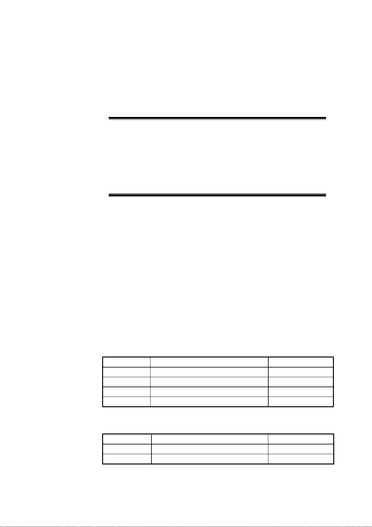
ZXCBTS products are classified based on different frequency bands and transmitter
powers. This manual serves for the installation of the following models:
Table 1.1-1 List of ZXCBTS Micro-BTS/Remote Stations (800MHz)
Model Name Rated Transmission Power
ZXCBTS M800T CDMA micro-BTS (800MHz) 10W
ZXCBTS M802T CDMA micro-BTS (800MHz) 20W
ZXCBTS R800T CDMA remote station (800MHz) 10W
ZXCBTS R802T CDMA remote station (800MHz) 20W
Table 1.1-2 List of ZXCBTS Micro-BTS/Remote Stations (1900MHz)
Model Name Rated Transmission Power
ZXCBTS M190T CDMA micro-BTS (1900MHz) 5W
ZXCBTS M191T CDMA micro-BTS (1900MHz) 10W
1-1
Page 24
ZXCBTS (V5.4) CDMA Micro Base Transceiver Station & Remote Station Installation Manual
Model Name Rated Transmission Power
ZXCBTS M192T CDMA micro-BTS (1900MHz) 20W
ZXCBTS R190T CDMA remote station (1900MHz) 5W
ZXCBTS R191T CDMA remote station (1900MHz) 10W
ZXCBTS R192T CDMA remote station (1900MHz) 20W
ZXCBTS products include micro-BTS and remote stations, working in the frequency
bands of 800MHz and 1.9GHz.
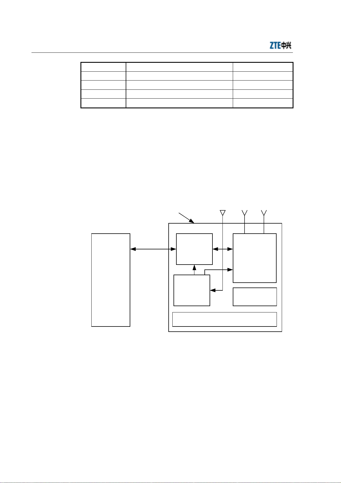
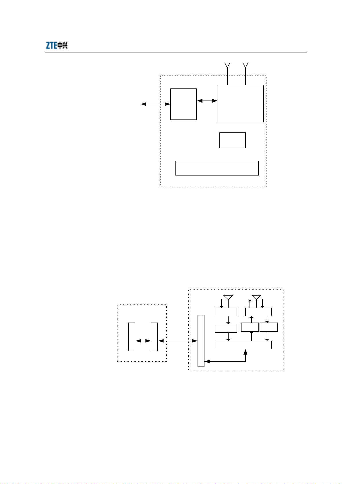
Micro-BTS system consists of Baseband Digital Subsystem (BDS), Timing &
Frequency Subsystem (TFS), power supply subsystem, lightning protection subsystem
and Radio Frequency Subsystem (RFS). The structure of
M800T/M802T//M190T/M191T/M192T micro-BTS is illustrated in the following
figure.
GPS antenna RF antenna
Micro-BTS
T1 (4)
BSC, macro-/
micro-BTS
Fig. 1.1-1 Structure of ZXCBTS M800T Micro-BTS
BDS
subsystem
(BDM)
TFS
subsystem
(GPSTM)
GPS, RF antenna feeder and power lightning
arrester
RFS subsystem
(MTRX, MPA,
MLNA, MDUP
and MDIV)
Power supply
Remote stations are similar to micro-BTS in structure, but different in replacing
Baseband Digital Module (BDM) with Remote Fiber Module (RFM) and removing
GPS Timing Module (GPSTM), for the clock signals of remote stations are
demodulated from the signals sent through optical fiber. The structure of remote
stations is illustrated in the following figure.
1-2
Page 25
Chapter 1 Overview
RF antenna
Optical
fiber
Fig. 1.1-2 Structure of Remote Stations
RFM
RF antenna feeder and power
lightning arrester
RFS (MTRX,
MDUP and MDIV)
Power
supply
Remote stations should cooperate with the macro-/micro-BTS to achieve the BTS
functions, so you need to configure Local Fiber Module (LFM) on micro-BTS or
Optical Interface Module (OIM) on micro-BTS for interworking with the remote
stations.
If the LFM is configured in a macro-BTS, the connection between the remote station
and the macro-BTS is illustrated in the following figure.
RX RXTX
DIV DUP
Macro-BTS
R
F
I
M
Fig. 1.1-3 Connection between Remote Station and Macro-BTS
L
F
M
Optical fiber
R
F
M
RX
MLNA
RX RX
Remote station
TX
MPA
TX
MTRX
RX
MLNA
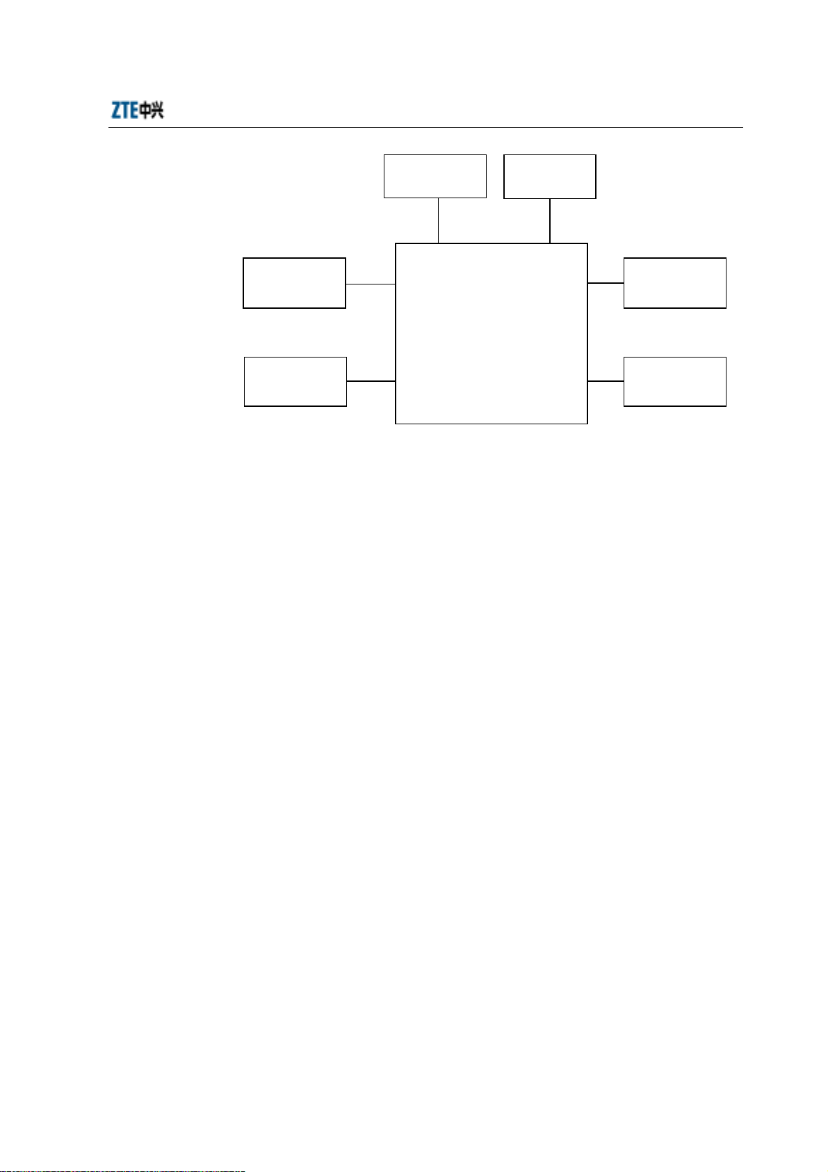
If the OIM is configured in a micro-BTS, the connection between the remote station
and the micro-BTS is illustrated in the following figure.
1-3
Page 26

ZXCBTS (V5.4) CDMA Micro Base Transceiver Station & Remote Station Installation Manual
RX RXTX
DIV DUP
RX
B
D
M
Micro-BTS
Fig. 1.1-4 Connection between Remote Station and Macro-BTS
O
I
M
Optical fiber
R
F
M
MLNA
RX RX
Remote station
MPA
TX
MTRX
RXTX
MLNA
1.2 Installation Overview
The hardware installation of micro-BTS/remote stations can be divided into the
following aspects:
1. Installing shelf and boards, connecting internal cables and setting DIP switches
2. Installing the power supply system
3. Installing the grounding system
4. Locating and installing the antenna, jumper cable and feeder cable, and testing
the antenna feeder system
5. Installing GPS and its feeder cables
6. Connecting trunk cables and assembling their connectors
7. Installing the alarm system for reporting abnormal temperature and humidity
See Fig. 1.2-1.
1-4
Page 27
Chapter 1 Overview
Install the power
supply system
Install the
grounding system
Fig. 1.2-1 Schematic Diagram of the Hardware Installation of Micro-BTS/Remote Station
1.3 Installation Flow
Install the equipment following the specified procedures strictly:
Install the GPS
Install the
antenna system
Install the ZXCBTS cabinet
Install the shelf
Check internal
cables
Set the DIP
switches
Connect trunk
cables
Install the
sunshade cover
1. Install the support;
2. Locate the cabinet on the support;
3. Secure the cabinet;
4. Install the sunshade cover (necessary for outdoor installation);
5. Connect power cables and grounding cables of the cabinet;
6. Connect T1 cables of the cabinet;
7. Install the primary antenna feeder system to connect with the RF cables;
8. Install the GPS;
9. Install and test the boards and modules, and set the DIP switches;
10. Check the installation.
See Fig. 1.3-1.
1-5
Page 28
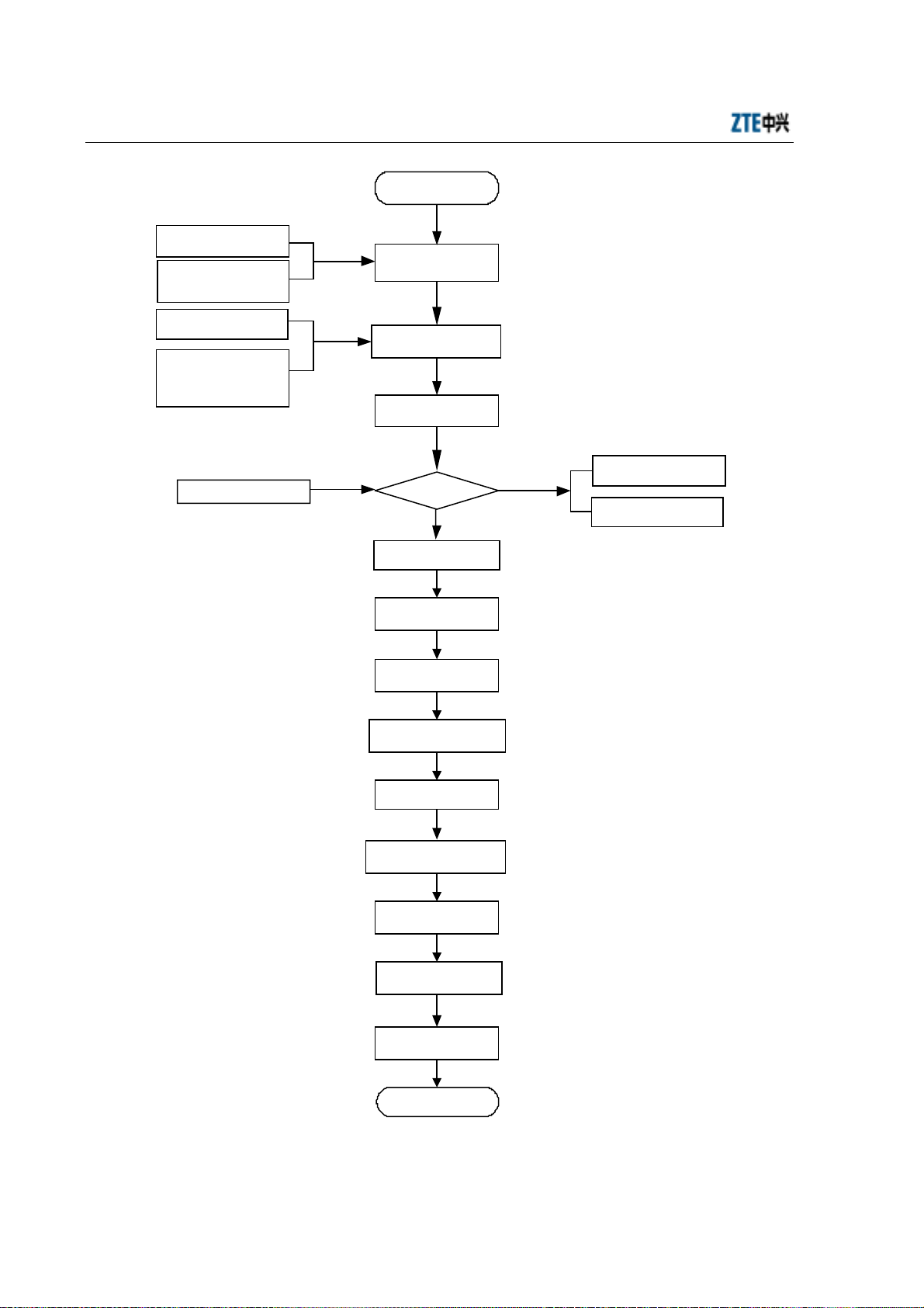
ZXCBTS (V5.4) CDMA Micro Base Transceiver Station & Remote Station Installation Manual
Start
Engineering Survey
Report
BTS Engineering
Design and
Construction Drawing
Environment
Acceptance Report
Cabling rack Power
supply system
Grounding system
Other accessories
Preparation for
engineering
installation
Check construction
conditions
Open-box inspection
Packing list
Goods are
correct
Yes
Install the shelf
Install the power
supply system
Install the
grounding system
Check cable connections
in the shelf
Connect trunk cables
Check the primary
antenna feeder system
No
Goods Error Feedback
List
Goods Replacement
Feedback List
Install the GPS
Set DIP switches
Hardware installation
check
End
Fig. 1.3-1 Hardware Installation Flow Diagram
1-6
Page 29

Chapter 1 Overview
1.4 Points for Attention
Pay attention to the following points during the installation: The installation personnel
should be trained to obtain the qualification entitled by ZTE and read this manual
before the installation.
1. Do not operate on the cabinet or any module when the power is on.
2. Observe the relative requirements strictly when installing the BTS.
3. Do not install the antenna feeder system in thunder weather.
4. Before the thunder storm season of each year comes, check whether the
lightning arrester is in good condition and is well contacted. If it is damaged,
replace it immediately.
5. When the installation of the cabinet completes, lock the door immediately. If the
door need be opened in case of maintenance, contact the professional personnel
for help.
1-7
Page 30

Page 31

2 Preparations
Summary
Describing the installation environment check.
Listing the installation tools.
Listing the technical documents needed for
installation.
2.1 Installation Environment Check
The items to check:
2.1.1 Checking Equipment Building Conditions
Check if the layout, height, bearing capability, shock-proof ability, doors and windows,
walls and troughs of the equipment building meet the requirements.
2.1.2 Checking Indoor Environment
Check the temperature, humidity, air pressure, ventilation condition, antistatic
protection measures, anti-interference measures, dustproof measures, rodent-resistant
measures, fire-protection facility, lighting condition, water supply and drainage system
of the equipment room.
To the highest priority, the equipment should be installed on the cool and dry walls
indoors with good ventilation; the fire-protection facility should be equipped; there
should be no caustic gas or smog in the room and no leakage on the roof; the
electromagnetic interference strength should be no more than 140dBµV/m
(0.01MHz~110000MHz). Or the equipment can be installed on the shady walls
outdoors with good ventilation and rain blocks. To the least priority, the equipment can
be installed on common walls, towers or high poles. The operating temperature range
of the equipment is between -40°C and +55°C, and the relative humidity range is
between 5% and 100%.
2-1
Page 32

ZXCBTS (V5.4) CDMA Micro Base Transceiver Station & Remote Station Installation Manual
2.1.3 Checking Power Supply System
Check the power supply ability and quality. A group of independent and stable
85V~138V (nominal 120V) AC power should be supplied to the equipment. It is
prohibited to share the power supply with other high-power telecom equipment or the
usually powered-down equipment.
2.1.4 Checking Grounding System
The standard grounding system should be equipped and the resistance should be less
than 5 ohm.
2.1.5 Checking Relative Devices
Check if the other devices relative to the normal operation of the equipment are in good
condition, such as interface device, transmission device, Digital Distribution Frame
(DDF) and Optical Distribution Frame (ODF).
2.2 Tools and Instruments
Prepare the tools and instruments needed for the installation in advance as listed in
Table 2.2-1.
Table 2.2-1 Tools and Instruments Needed for the Installation
Type Name
Special tools
Drilling tools
General tools
One cutter for assembling feeder cable connectors
One 75-ohm coaxial cable stripper
75-ohm coaxial crimping plier
One multi-functional crimping plier
One multimeter
One SiteMaster standing wave ratio tester
One earth resistance tester
One percussive drill
Several drill bits
One cleaner
One power connector board (with at least three two-pin and three-pin
sockets respectively; the current capacity is more than 15 amp.)
Three cross screw-drivers (4”, 6” and 8”)
Three straight screw-drivers (4”, 6” and 8”)
Four adjustable wrenches (6”, 8”, 10” and 12”)
2-2
Page 33

Chapter 2 Preparations
Type Name
Two spanners (17” and 19”)
One hexagon spanner
One socket wrench
One 5kg nail hammer
One 300W electric iron and one 40W electric iron
One coil of solder wires
One 50m tape measure
One 5m steel tape measure
One 400mm horizontal ruler
Measurement tools
Protection tools
Locksmith tools
Assistant tools
One inclinometer
One compass
One multimeter
Ruler
One plumb
Antistatic wrist strap
Safety helmet, slip-proof gloves
One hacksaw, several saw blades
One sharp nose plier (8”)
One diagonal plier (8”)
One slip joint plier (8”)
One vice (8”)
A set of files (middle)
One tweezers
One paint brush
One scissors
One dryer
One solder removal tool
One hydraulic pressure pliers
One crowbar
Pulley group
Rope
Ladder
Forklift
2.3 Technical Documents
Prepare the following technical documents:
1. Engineering Survey Report, BTS Engineering Design and Construction Drawing,
Environment Acceptance Report
2-3
Page 34

ZXCBTS (V5.4) CDMA Micro Base Transceiver Station & Remote Station Installation Manual
Engineering Survey Report should be filled by the technical engineers of the
equipment provider during site survey. If they can not carry out the survey in
time, you should survey the site, fill in the report and then send it to the
equipment provider. This report is used for the preparation of construction
materials.
BTS Engineering Design and Construction Drawing should be prepared by the
design unit you entrusted, and a copy should be provided to the equipment
provider before the delivery.
Environment Acceptance Report is used by the technical engineers of the
equipment provider to check the construction environment during site survey. If
any inconformity is found, you are required to solve the problem. Before the
construction, the second check will be implemented.
2. ZXCBTS(V5.4)CDMA Micro Base Transceiver Stations/RF Remote Stations
Installation Manual, ZXCBTS(V5.4)CDMA Micro Base Transceiver Stations/RF
Remote Stations Technical Manual, ZXCBTS(V5.4)CDMA Micro Base
Transceiver Stations/RF Remote Stations Hardware Manual,
ZXCBTS(V5.4)CDMA Micro Base Transceiver Stations/RF Remote Stations
Maintenance Manual
3. Installation Acceptance Report, Test Acceptance Report
Installation Acceptance Report and Test Acceptance Report should be offered to
you by the equipment provider during delivery. Installation Acceptance Report
is filled after the BTS installation completes. Test Acceptance Report is filled
during the BTS commissioning.
2-4
Page 35

3 Open-box Inspection
Summary
Describing the inspection procedures.
Describing the open-box procedures.
3.1 Checking Packing List and Goods
Caution
Because ZXCBTS equipment is expensive, ensure that it is packed well and the
flags for avoiding water and vibrations are marked. Load and unload the
equipment gently, and avoided damage from sunshine and rain.
1. Check the “ZTE delivery sheet”.
2. Open-box inspection should be done by the engineering supervisor and your
representative. First, check if the total quantity of the goods is correct according
to the packing list, if the packing boxes are in good condition, and if the delivery
location is the right installation site.
3. Next, open the boxes and the engineering supervisor should check the goods
based on the packing list. Open-box Inspection Report is put in the packing box
numbered 1#. Open the 1# box and take out the Open-box Inspection Report to
check if the total quantity of the goods is consistent with the checklist, and then
archive the report.
4. During the inspection, if loss of goods, lack of goods, error delivery or any
damage is found, find out the cause and feedback to the ZTE headquarter for
handling.
5. The goods are packed in either cartons or wooden boxes. You need to open them
on site using different tools.
3-1
Page 36

ZXCBTS (V5.4) CDMA Micro Base Transceiver Station & Remote Station Installation Manual
3.2 Packaging
Note
The cabinets of micro-BTS and remote stations are the same in structure, so is
the packaging method.
Put the support and other accessories of the ZXCBTS cabinet into the wooden box.
In the wooden box, the cabinet is packed with foam boards, a bubble bag and a plastic
bag. After opening the box, you need not uplift it but directly take the equipment out.
When carrying the box, be cautious to prevent the cabinet from being damaged.
The packing box for the ZXCBTS cabinet is shown in Fig. 3.2-1.
Goods:
CDMA micro -BT S
ZTE CORPORATION
ZTE Plaza, Keji Road South, Hi-Tech Industrial
Park, Nanshan District, Shenzhe n, P.R.Chi na
Postcode: 518057
Tel: (+86755) 6790000
Customer Support Cente r: 8008301118
Net Weight: (Kg)
Volume: 81x52x40 (cm)
Qty. :
Packing List:
Fig. 3.2-1 Packing Box for ZXCBTS Cabinet
3.3 Open-box Procedures
Follow the steps below to open the box:
1. Open the cover board.
2. Remove the foam boards.
3. Take the micro-BTS out directly.
See Fig. 3.3-1.
3-2
Page 37

Chapter 3 Open-box Inspection
Accessories
Micro-BTS
)
g
K
(
C
D
M
A
m
i
c
r
o
-
B
T
S
Z
T
Z
T
E
C
O
R
P
O
R
A
T
I
O
E
P
l
a
z
a
,
K
P
e
j
a
i
r
k
R
,
o
a
N
P
o
s
t
c
o
N
d
T
e
l
:
(
+
8
6
C
u
s
t
o
m
e
r
d
a
e
7
ns
S
o
h
u
a
t
n
h
,
D
H
i
s
t
i
-
r
T
i
c
e
t
c
,
h
S
:
5
1
8
0
5
7
5
5
)
6
7
9
0
0
00
S
u
p
p
o
r
t
C
e
n
t
e
r
h
I
n
e
d
n
u
z
:
8
0
0
8
s
he
t
r
i
n
a
,
l
P
.
R
.
C
h
i
n
a
3
01
1
1
8
s
d
o
o
G
W
t
e
N
u
l
o
V
y
t
Q
c
a
P
:
:
t
h
g
i
e
x
1
8
:
e
m
:
.
s
i
L
g
n
i
k
)
m
c
(
0
4
x
2
5
:
t
Fig. 3.3-1 Schematic Diagram for Opening a Box
3-3
Page 38

Page 39

4 Installation of Cabinet
Summary
Describing the procedures to install the
micro-BTS/remote station cabinet
Describing the possible installation modes
4.1 Installation Flow
Note
The cabinets of ZXCBTS micro-BTS/remote stations are the same in structure,
so is the installation method.
The cabinet can be installed in two modes: on pole or on wall. The installation flow is
shown in Fig. 4.1-1.
4-1
Page 40

ZXCBTS (V5.4) CDMA Micro Base Transceiver Station & Remote Station Installation Manual
Installation on pole
Install t he sup p ort
Outdoors
Install the sunshade cover
Install t he cabinet
Ins tallation check
End
Installation on wall
Ins tall the support
Indoors
4.2 Installation Modes
Note
The cabinets of ZXCBTS micro-BTS/remote stations are the same in structure,
so is the installation method.
As shown in Fig. 4.1-1, the cabinet can be installed either on pole or on wall based on
the actual environment.
4.2.1 Installing Cabinet on Pole
1. Disassemble the support from the cabinet.
2. Secure the support onto the pole with fixing plates and 260mm-long bolts. The
diameter of the pole should be between 60mm and 90mm. 75mm is
recommended. See Fig. 4.2-1.
If the equipment is to be installed outdoors, face the front side southward and
Fig. 4.1-1 Flow of Installing the Cabinet
the back side northward (This rule is applicable to the case that the equipment is
4-2
Page 41

Chapter 4 Installation of Cabinet
installed in the Northern Hemisphere. If it is installed in the Southern
Hemisphere, the opposite rule should be applied).
3. Install the sunshade cover onto the support with four M4 bolts. See Fig. 4.2-4.
4. Hold the cabinet to hang it onto the support, then push it into the shelf. See Fig.
4.2-2.
5. Align the bolt holes on the support with those on the cabinet, and then screw
down four M8 hexagon bolts. See Fig. 4.2-3.
6. On the cabinet base there are hangers for rope. If necessary, use the rope to hang
the cabinet onto the pole.
See Fig. 4.2-1 for the schematic diagram of cabinet fastened on pole.
Bolt
Flat washer
Support
M12 nut,
spring washer,
flat washer
Pole
Fixing plate
Fig. 4.2-1 Schematic Diagram of Fastening the Cabinet onto the Pole (step 1)
4-3
Page 42

ZXCBTS (V5.4) CDMA Micro Base Transceiver Station & Remote Station Installation Manual
Fig. 4.2-2 Schematic Diagram of Fastening the Cabinet onto the Pole (step 2)
Fig. 4.2-3 Schematic Diagram of Fastening the Cabinet onto the Pole (step 3)
4-4
Page 43

Chapter 4 Installation of Cabinet
Fig. 4.2-4 Schematic Diagram of the Cabinet Fastened onto the Pole
Caution
For your safety, be sure to wear the safety belt when working at heights and
the safety helmet when working at grounds. It is prohibited to work in
thunder storm weather.
4-5
Page 44

ZXCBTS (V5.4) CDMA Micro Base Transceiver Station & Remote Station Installation Manual
4.2.2 Installing Cabinet on Wall
1. Disassemble the support from the cabinet.
2. Mark four points on the wall based on the four holes on the support, and then
drill four holes with a percussive drill (using M12 drill bit). Secure the support
onto the wall with four M10 expansion bolts. See Fig. 4.2-5.
3. Hold the cabinet to hang it onto the support, and then push it into the shelf.
4. Align the bolt holes on the support with those on the cabinet, and then screw
down four M8 hexagon bolts.
5. Install the sunshade cover if the equipment is to be installed outdoors.
See Fig. 4.2-6 for the schematic diagram of installing cabinet on wall.
Wall
Support
Exp ansion bolt
Hexagon n ut
Washer
Fig. 4.2-5 Schematic Diagram of Installing the Support onto the Wall
4-6
Page 45

Chapter 4 Installation of Cabinet
Fig. 4.2-6 Schematic Diagram of Installing the Cabinet onto the Wall
Note
The modules and cables in micro-BTS (including ultra-wide coverage
micro-BTS) and remote stations have been installed, connected and tested
before delivery. Before commissioning, you only need to check if they are loose
due to conveyance. Refer to Chapter 7 for the connection of cables between
cabinets.
According to the configuration requirement, you might need to add optical
fiber modules or CSM5000 expansion modules in the expansion slots of the
corresponding BDM board.
If any fault occurs, the maintenance personnel can refer to this manual for
simple maintenance.
4-7
Page 46

Page 47

5 Installation of Power Supply System
Summary
Describing the methods for installing the power
supply system..
Describing the procedures to install the power
supply system..
5.1 Introduction to Power Cables
The micro-BTS/remote stations are supplied by 120V AC power or -48V DC power.
AC micro-BTS are supplied by 120V AC power, and DC micro-BTS are supplied by
-48V DC power.
5.1.1 -48V DC Power Cable
The ZTE -48V DC ZXCBTS equipment is equipped with a piece of 10m-long cable,
which can meet the installation requirement in most cases. If you need to assemble the
cable on site in special cases, follow the instructions in this section. The DC power
cable connector is a four-pin connector, and the power cable adopts four-core cable, as
shown in Fig. 5.1-1. The corresponding relationship between the core wires and the
binding posts are listed in Table 5.1-1.
Fig. 5.1-1 Four-pin Connector and Four-core Power Cable
5-1
Page 48

ZXCBTS (V5.4) CDMA Micro Base Transceiver Station & Remote Station Installation Manual
Table 5.1-1 Corresponding Relationship between Core Wires and Binding Posts
Binding Post No. Color of Core Wire Power Polarity
1 Blue -48V
2 Red -48V
3 Black -48VGND
4 Olivine -48VGND
5.1.2 120V AC Power Cable
The ZTE 120V AC ZXCBTS equipment is equipped with a piece of 10m-long cable,
which can meet the installation requirement in most cases. If you need to assemble the
cable connector on site in special cases, follow the instructions in this section. The AC
power cable connector is a three-pin connector, and the power cable adopts three-core
cable. Refer to Table 5.1-2 for the corresponding relationship between the core wires
and the binding posts.
Table 5.1-2 Corresponding Relationship between Core Wires and Binding Posts
Binding Post No. Color of Core Wire Power Polarity
1 Yellow and green PE
2 Brown L
3 Blue N
5.2 Connection of Power Cables
120V AC power supply and -48V DC power supply are used for the micro-BTS and
remote stations. A waterproof connector is used to connect the power to the POWER
terminal at the bottom of a cabinet, as shown in Fig. 5.2-1.
1. Select a suitable type of power cable.
If the cabinet is installed outdoors, outdoor shielded power cables should be
used for power supply, which can withstand the influences of ultraviolet lights,
rains and temperature changes. If common three-core AC power cables are used
in special cases, PVC pipes should be added for protection.
If the cabinet is installed indoors, common three-core power cables can be used
for power supply.
5-2
Page 49

Chapter 5 Installation of Power Supply System
a
r
R
m
2. Power cables should be laid in order. If they are laid in parallel with T1 signal
cables, an interval of 200mm is required between them.
3. Upon bundling of power cables, the space between two cable ties should be less
than 0.5m to prevent friction with the tower upon swing of cables and avoid
damage of power cable sheath.
The power cable with
round connector fo
connecting the POWE
terminal at the botto
of the cabinet
PGND terminal
of the cabinet
Fig. 5.2-1 Connection of Power Cables and Grounding Cables at the Bottom of a Cabinet
5.3 Assembling Power Cable Connector
5.3.1 Assembling -48V DC Power Cable Connector
Step 1: Put the connector components 1, 2, 3, 4 and 5 onto the cable, as shown in Fig.
5.3-1.
4
5
3
2
1
Fig. 5.3-1 Assembling a Power Cable Connector (step 1)
5-3
Page 50

ZXCBTS (V5.4) CDMA Micro Base Transceiver Station & Remote Station Installation Manual
Step 2: Strip the 17mm-long sheath off the four-core cable at the end to be welded. If
the sheath of more than 17mm is stripped, the component 3 cannot press the cable tight;
if less than 17mm, inconvenience might be caused for installation. See Fig. 5.3-2.
4
3
2
1
5
Fig. 5.3-2 Assembling a Power Cable Connector (step 2)
Step 3: Strip the 5mm-long insulation layer off the four core wires respectively, twist
up the copper core wires and brush a slice layer of soldering tin on them, and then put a
10~15mm-long heat-shrink tube onto each core wire.
Step 4: Joint the core wires respectively with the binding posts of the component 6 by
welding them, push the heat-shrink tubes to the proper position and then make them
shrink, as shown in Fig. 5.3-3. Refer to Table 5.1-1 for the corresponding relationship
between the core wires and the binding posts.
4
3
2
1
6
5
Fig. 5.3-3 Assembling a Power Cable Connector (step 4)
5-4
Page 51

Chapter 5 Installation of Power Supply System
Step 5: Screw to connect the component 5 with the component 6, as shown in Fig.
5.3-4.
4
3
2
1
6
5
Fig. 5.3-4 Assembling a Power Cable Connector (step 5)
Step 6: Push the components 2, 3 and 4 into the component 5, and then screw down the
component 1 onto the component 5. Be sure to screw the component 1 but not 5. See
Fig. 5.3-5.
1
6
5
Fig. 5.3-5 Assembling a Power Cable Connector (step 6)
5.3.2 Assembling 120V AC Power Cable Connector
The steps for assembling an AC power cable connector are the same as that for
assembling a DC power cable connector. The only difference is that the three-pin
connector and three-core power cable are used for AC power cables. Refer to the
preceding contents for the procedures and Table 5.3-1 for the corresponding
relationship between the core wires and the binding posts.
5-5
Page 52

ZXCBTS (V5.4) CDMA Micro Base Transceiver Station & Remote Station Installation Manual
Table 5.3-1 Corresponding Relationship between Core Wires and Binding Posts
Binding Post No. Color of Core Wire Power Polarity
1 Yellow and green PE
2 Brown L
3 Blue N
5-6
Page 53

6 Installation of Grounding System
Summary
Describing the method for installing the grounding
system
6.1 Introduction to the Grounding System
This section details the procedures to install the grounding system, including grounding
copper busbar and feeder cable grounding kit.
Grounding aims to protecting both the human being and the equipment against
lightning shock and electromagnetic interference.
The grounding system is composed of indoor groundings, outdoor groundings and
underground grounding net.
The grounding system of a ultra-wide coverage micro-BTS includes protection
grounding on the chassis, lightning arrester for RF components in the cabinet, for GPS
antenna, for T1 cables, for 120V AC power and for feeder cable grounding kit.
The customer needs to complete the construction of the basic grounding net and the
grounding system of the tower and other buildings, and offer the points for connecting
the indoor and outdoor grounding busbars to the grounding net through different
2
50mm
the grounding copper busbar, and the conductor led from the -48VGND of the shelf is
connected to the DC power copper busbar.
Each feeder cable should be connected to the outdoor grounding copper busbar through
wires. The conductor led from the PGND terminal of the shelf is connected to
the cable grounding kit before being led into the equipment room. See Fig. 6.1-1.
6-1
Page 54

ZXCBTS (V5.4) CDMA Micro Base Transceiver Station & Remote Station Installation Manual
Tower platform
Feeder cable gro un din g kit
Grounding cable (35mm
DC power rack
PGNDs of all devices in the
equipment room (including the
cabling rack) are connected to
the indoor grounding busbar
Outdoor
grounding
busbar
Feeder cable
Grounding cable (50mm
Indoor
gro unding
busbar
Micro-BTS
2
)
Fig. 6.1-1 Schematic Diagram of Grounding Connections
Other devices
2
)
U
6.2 Installing Grounding System
6.2.1 Installing Outdoor Grounding Copper Busbar
The outdoor grounding copper busbar functions in lightning protection. It is usually
installed on the wall outside the equipment room, and the best position is right under
the feeder cable window or on the rain-proof wall of the feeder cable well on the top of
a building.
6-2
Page 55

Chapter 6 Installation of Grounding System
In actual installation, first determine the position for the copper busbar based on the
engineering design drawing, and then install the busbar on the wall with expansion
bolts. See Fig. 6.2-1 for the appearance of the grounding copper busbar.
Fig. 6.2-1 Appearance of a Grounding Copper Busbar
6.2.2 Installing the Grounding System of Micro-BTS
The cabinets of ultra-wide coverage micro-BTS/remote stations are equipped with
PGND terminals, as shown in Fig. 6.2-2. The PGND terminal is connected to the
indoor grounding copper busbar via the 16mm
the equipment is installed outdoors, the PGND terminal is connected with the
grounding cable from the tower or from the top of the building in the crimping
connection mode.
2
yellow or olivine conducting wire. If
6-3
Page 56

ZXCBTS (V5.4) CDMA Micro Base Transceiver Station & Remote Station Installation Manual
PGND
terminal of
the cabinet
Fig. 6.2-2 Connection of Power Cable and PGND Cable at the Bottom of a Cabinet
6.2.3 Installing Feeder Cable Grounding Kit
Caution:
It is prohibited to install the grounding kit in thunderstorm weather; otherwise,
the installation personnel might be hurt.
When installing the grounding kit, be sure to keep the feeder cable at the joint
straight.
6.2.3.1 Grounding Principles of Primary Feeder Cable
1. Generally, each primary feeder cable should be grounded at least three times for
lightning protection, that is, on the tower platform, between the tower and the
outdoor cabling rack, and on the wall before the feeder cable is led into the
equipment room. If the primary feeder cable is more than 60 meters long, a
lightning grounding kit should be installed every 20 meters.
2. The antenna feeder system, antenna mount and newly-installed cabling rack
should all be welded to the lightning protection net of the building. The feeder
cable should also be grounded at three points, that is, on the antenna pole, on the
rooftop, and on the wall before the feeder cable is led into the equipment room.
3. Before leading the primary feeder cable along the outdoor cabling ladder from
the top of the building to the equipment room, check whether the cabling ladder
is grounded. If not, request the network operator to accomplish it as soon as
possible.
6-4
Page 57

Chapter 6 Installation of Grounding System
6.2.3.2 Procedures to Install a Grounding Kit
1. Prepare such tools as paper knife, straight screwdriver, spanner and sharp nose
pliers.
2. Choose a suitable position for installing the grounding kit, and cut the sheath off
the 7/8" feeder cable based on the size of the grounding kit. The structure of a
grounding kit is shown in Fig. 6.2-3.
Grounding wire clip
Grounding terminal
3. Lead the grounding cable of the lightning grounding kit to the grounding net.
Feeder cable
Grounding cable
Out-layer copper
core of feeder cable
Sheet cop per of
feeder cable
Fig. 6.2-3 Structure of a Grounding Kit
Keep the angle between the grounding cable and the primary feeder cable no
more than 15°.
If the antenna feeder system is installed on a tower, lead the grounding cable
downward along the tower.
If the antenna feeder system is installed on the top of a building, lead the
grounding cable to the lightning protection net.
4. Before installing the grounding kit, wrap the waterproof adhesive tape around
the grounding cable near the grounding copper for sealing, as shown in Fig.
6.2-4.
6-5
Page 58

ZXCBTS (V5.4) CDMA Micro Base Transceiver Station & Remote Station Installation Manual
Fig. 6.2-4 Schematic Diagram of Wrapping Waterproof Adhesive Tape Around the Grounding Cable
5. Clamp the external conductor with the grounding copper and clip tightly.
6. Seal the joint between the grounding kit and the feeder cable as follows:
First wrap the waterproof adhesive tape and then the PVC tape around the joint.
Wrap the waterproof adhesive tape circularly from bottom upward, and then
from top downward, finally from bottom upward again. Note that the next circle
covers 1/2 of the previous circle.
7. Connect the grounding terminal of the grounding kit to the tower body or the
cabling rack on the top of the building (the cabling rack is connected to the
lightning protection net). Remove the paint and oxide at the junction within the
radius of 13mm and then coat the clean area with antioxidant cream. After the
connection, paint the area with antirust paint.
8. Before the primary feeder cable is led into the equipment room, connect the
grounding terminal of the grounding kit to the outdoor grounding busbar.
6-6
Page 59

7 Connection of Cables
Summary
Describing the connection of internal cables.
Describing the connection of external cables.
7.1 Checking Internal Cable Connections
7.1.1 Type and Configuration of Internal Cables
There are 422 or 485 internal cables totally. Refer to Table 7.1-1 for the types and
configurations of internal cables in micro-BTS/remote stations.
Table 7.1-1 List of Types and Configurations of Internal Cables
Type Name Applied Equipment
RF cables
RF21 Single-carrier 800M micro-BTS/remote stations
RF22 Single-carrier and double-carrier 800M micro-BTS/remote stations
RF23 Single-carrier and double-carrier 800M micro-BTS/remote stations
RF24 Single-carrier and double-carrier 800M micro-BTS/remote stations
RF25 All micro-BTS/remote stations
RF26 Single-carrier and double-carrier 800M micro-BTS/remote stations
RF27 Single-carrier and double-carrier 800M micro-BTS/remote stations
RF28 Single-carrier and double-carrier 800M micro-BTS/remote stations
RF32 Single-carrier 1.9G micro-BTS/remote stations
RF33 Single-carrier and double-carrier 1.9G micro-BTS/remote stations
RF34 Single-carrier and double-carrier 1.9G micro-BTS/remote stations
RF35 Single-carrier 1.9G micro-BTS/remote stations
RF36 Single-carrier and double-carrier 1.9G micro-BTS/remote stations
RF37 Single-carrier 1.9G micro-BTS/remote stations
RF38 Single-carrier and double-carrier 1.9G micro-BTS/remote stations
RF42 All double-carrier micro-BTS/remote stations
7-1
Page 60

ZXCBTS (V5.4) CDMA Micro Base Transceiver Station & Remote Station Installation Manual
Type Name Applied Equipment
RF43 All double-carrier micro-BTS/remote stations
RF29 All single-carrier and double-carrier micro-BTS
RF30 Single-carrier and double-carrier 800M micro-BTS
RF31 Single-carrier and double-carrier 800M micro-BTS
Clock cables
Communication
cables
Power cables
Fan cables
Grounding
cables
Alarm cables
RF39 Single-carrier and double-carrier 1.9G micro-BTS
RF40 All single-carrier and double-carrier remote stations
RF41 All single-carrier and double-carrier remote stations
BDM-GPS All single-carrier and double-carrier micro-BTS
MPA
CONTL
RXTDX All micro-BTS/remote stations
DCDX01 All micro-BTS/remote stations
DCDX02 All micro-BTS/remote stations
DCDX03 All micro-BTS/remote stations
ACDX01 All AC-powered micro-BTS/remote stations
ACDX02 All AC-powered micro-BTS/remote stations
ACDX03 All micro-BTS/remote stations configured with heater
ACDX04 All AC-powered micro-BTS/remote stations
F-DC
PWR-001
F-DC
PWR-002
F-DC
PWR-003
F-FAN-004 All single-carrier and double-carrier micro-BTS
F-FAN-005 Single-carrier and double-carrier 20W micro-BTS/remote stations
F-FAN-006 Single-carrier and double-carrier 20W micro-BTS/remote stations
DX01 All micro-BTS/remote stations
DX02 All micro-BTS/remote stations
DX03 All micro-BTS/remote stations
MONDX01 All micro-BTS/remote stations
MONDX02 All micro-BTS/remote stations
DX04 All single-carrier and double-carrier micro-BTS
DX05 All single-carrier and double-carrier remote stations
DX06 All micro-BTS/remote stations
All micro-BTS/remote stations
All DC-powered micro-BTS/remote stations
All DC-powered micro-BTS/remote stations
All DC-powered micro-BTS/remote stations
Among these cables, only ACDX04 (AC power cable) and F-DC PWR-002 (DC power
cable) are delivered with the equipment, and other cables have been connected in the
equipment before delivery.
7-2
Page 61

Chapter 7 Connection of Cables
7.1.2 Connection of Internal Cables
Refer to Appendix B for the connection of internal cables.
7.2 Connecting External Cables
7.2.1 Connecting Optical Fiber
Note
The optical fiber connectors of micro-BTS/remote stations are SC connectors.
The ODF or optical connection box provided is equipped with FC connectors by
default. If there are special requirements on the connectors, contact ZTE for
customization.
7.2.1.1 Selecting Optical Fiber
Different optical fibers are used for the connections between macro-/micro-BTS and
remote stations.
1. If a remote station is near to a relative micro-BTS, optical fiber is used directly.
The optical fiber adopts waterproof pigtail cable, and both ends are equipped
with waterproof blockers and SC connectors. See Fig. 7.2-1 for the structure of
the optical fiber.
Optical fiber core
wire (0.7m)
SC/ P C c o n ne c t o r
Waterproof
blo cker
Single-mode waterproof
pigtail cable
Optical fiber core
wire (0.7m)
Fig. 7.2-1 Structure of Optical Fiber (1)
7-3
Page 62

ZXCBTS (V5.4) CDMA Micro Base Transceiver Station & Remote Station Installation Manual
The core wires at both ends are 0.7m long. Both ends of the optical fiber can
connect either a micro-BTS or a remote station.
You can choose 10m/20m/50m/100m-long optical fiber for this connection
based on the actual situation.
2. If an outdoor remote station is near to a relative indoor macro-BTS, optical fiber
is used for connecting them directly. The optical fiber adopts waterproof pigtail
cable, with both ends being SC connectors. In addition, one end is equipped with
a waterproof blocker. See Fig. 7.2-2 for the structure of the optical fiber.
Optical fiber core
wire (3m)
SC/PC
connector
Single-mode waterproof
pigtail cable
Waterproof blocker
Optical fiber core
wire (0.7m)
Fig. 7.2-2 Structure of Optical Fiber (2)
The core wires of the end equipped with a waterproof blocker are 0.7m long,
and those of the other end are 3m long. The end with a waterproof blocker is to
be connected with the remote station, and other end is used to connect the
macro-BTS.
You can choose 50m/100m-long optical fiber for this connection based on the
actual situation.
3. If a remote station is far from a relative macro-BTS and an ODF or optical
connection box is required, two pieces of optical fiber should be used for
connecting the macro-BTS with the ODF and the ODF with the remote station
respectively.
7-4
Page 63

Chapter 7 Connection of Cables
1) Connection between the macro-BTS and the ODF
The indoor-type optical fiber is adopted, with one end being SC/PC connectors
and the other end being FC/PC connectors. See Fig. 7.2-3 for the structure of the
optical fiber.
SC/PC connector
FC/PC connect or
Single-mode
optical fiber
Fig. 7.2-3 Structure of Optical Fiber (3)
The SC/PC connectors are used to connect the macro-BTS, and the FC/PC
connectors are used to connect the ODF.
There is only one option for this connection: 30m-long optical fiber.
2) Connection between the ODF and the remote station
The optical fiber adopts waterproof pigtail cable. The end equipped with a
waterproof blocker uses SC/PC connectors, and the other end offers FC/PC
connectors. See Fig. 7.2-4 for the structure of the optical fiber.
Optical fiber core wire
(3m)
SC/PC connector
Single-mode waterproof
pigtail cable
Waterproof
blocker
FC/PC connector
Optical fiber core wire
(0.7m)
Fig. 7.2-4 Structure of Optical Fiber (4)
7-5
Page 64

ZXCBTS (V5.4) CDMA Micro Base Transceiver Station & Remote Station Installation Manual
The core wires of the end equipped with a waterproof blocker are 0.7m long,
and those of the other end are 3m long. The end with a waterproof blocker is to
be connected with the remote station, and the other end is to be connected with
the ODF.
You can choose 50m/100m-long optical fiber for this connection based on the
actual situation.
Caution: If the ODF uses cubical connectors, contact ZTE in advance.
7.2.1.2 Laying Optical Fiber
1. Connecting optical fiber for a micro-BTS/remote station
Because the end of the optical fiber for connecting a micro-BTS/remote station
is equipped with a waterproof blocker, you need to remove the cover of the
optical interface at the bottom of a micro-BTS/remote station first, insert the
pigtail fiber into the cabinet, and then screw down the waterproof blocker into
the optical interface, as shown in Fig. 7.2-5.
Fig. 7.2-5 Schematic Diagram of Connecting Optical Fiber
Waterproof
blocker
Opt ical
fiber
2. Connecting optical fiber for a macro-BTS
If the optical fiber is used to connect the Local Fiber Module (LFM) of a
macro-BTS, first insert the optical fiber into an interface on the front panel of
7-6
Page 65

Chapter 7 Connection of Cables
the LFM, lay the optical fiber along the horizontal cabling trough on the top of
the TRX layer, and then along the vertical cabling trough on the left of the shelf;
next, open the cover of the standby interface marked with “BTM ANT” on the
top of the macro-BTS, pull the optical fiber out of the shelf and then lay it onto
the cabling rack on top.
3. Requirements for laying optical fiber
The optical fiber should be arranged in order, with the interval for cable ties less
than 0.5m.
The minimum bending radius of the outdoor-type optical fiber is 90mm, and that
of the indoor-type optical fiber is 30mm.
7.2.2 Connecting Multi-carrier Interconnection RF Cables
If a double-carrier & single-sector micro-BTS/remote station is required, two cabinets
need be configured. These two cabinets should be connected by cables to achieve
transmission of diversity antenna signals.
When a micro-BTS cabinet and a remote station cabinet form a double-carrier &
single-sector micro-BTS system, two pieces of RF cables need be added to
cross-connect the RFE-ANT0 interface with the EXTEND interface at the bottom of
the two cabinets respectively.
Similarly, when two double-carrier remote station cabinets form a double-carrier
remote station and it is used in cooperation with a double-carrier macro-BTS, two
pieces of RF cables need be added to cross-connect the RFE-ANT0 interface with the
EXTEND interface at the bottom of the two cabinets respectively.
Refer to Appendix B for the configuration of internal cables in a double-carrier system.
The interconnection RF cable is 3m long, with both ends being RF N connectors. It is a
finished product delivered with cabinets. It is named as “F-RF05-009”. See Fig. 7.2-6
for the cable connections between two cabinets.
7-7
Page 66

ZXCBTS (V5.4) CDMA Micro Base Transceiver Station & Remote Station Installation Manual
(3m)
Micro-BTS/remote
station
EXTEND
RFE-ANT0
Interconnection RF
cable
Fig. 7.2-6 Connection of Interconnection RF Cables
7.2.3 Waterproof Processing of Joints
In case of double-carrier configuration, the joints between the sockets at the bottom of
Remote station
EXTEND
RFE-ANT0
the cabinets and the connectors of the interconnection RF cables should be wrapped
with waterproof adhesive tape. In addition, the joint between the socket at the bottom
of a 20W micro-BTS (M802T micro-BTS) cabinet and the connector of the external
fan cable should also be wrapped with the adhesive tape. You need to do the following:
1. Secure the relative connectors and sockets.
2. Implement waterproof processing to the joints.
1) Wrap the joints with the waterproof adhesive tape from the top of the connectors.
The first layer should be wrapped in the same direction as for fastening the cable
connectors.
2) Stretch the tape with force and wrap it circularly for three layers totally. Note
that the next circle covers 1/2 of the previous circle, and the wrap stops at the
position about 10cm away from the joint.
3) Grip the joint with force to make the tape stuck firmly with the joint.
7-8
Page 67

Chapter 7 Connection of Cables
4) Wrap two layers of PVC tape around the waterproof adhesive tape in the same
way as for wrapping the waterproof adhesive tape.
5) Finally wrap a layer of anti-ultraviolet tape.
7.2.4 Connection of Trunk Cables
There are T1 interfaces at the bottom of the primary cabinet of a micro-BTS for
connecting T1 cables (100-ohm coaxial cables), as shown in Fig. 7.2-7.
T1 cable
Fig. 7.2-7 Connection of T1 Cables
1. Select T1 cables.
Micro-BTS can be installed outdoors, so PE-sheath T1 cables are used generally.
If common T1 cables are used in an outdoor micro-BTS, PVC pipe should be
added for protection.
2. Lay the T1 cables in order. Keep T1 cables and AC power cables separate with
distance of more than 200mm.
3. When laying T1 cables on a tower, the space between two cable ties should be
less than 0.5m to prevent friction with the tower upon swing of cables and avoid
damage of T1 cable sheath.
7-9
Page 68

Page 69

8 Installation of Primary Antenna Feeder
System
Summary
Describing the composition of the primary antenna
feeder system.
Describing the procedures to install the primary
antenna feeder system.
8.1 Preparations
Before installing the primary antenna feeder system, check the qualification of the
installation personnel for working at heights, installation environment, security
measures, installation tools and system components, for the purpose of ensuring the
successful installation.
8.1.1 Installation Personnel
The antenna feeder system is installed by the professional installation personnel under
the monitoring of the installation supervisor.
The installation supervisor should be familiar with the materials, tools and operations
for the installation, who is responsible for assigning suitable work for the installation
personnel and recording the actual engineering data.
The installation personnel should be skillful and healthy. Those who work at heights
should have obtained the corresponding qualification, have no acrophobia, observe the
security regulations, and have purchased the personal accident insurance. In addition,
they are prohibited from drinking alcohol when working.
8-1
Page 70

ZXCBTS (V5.4) CDMA Micro Base Transceiver Station & Remote Station Installation Manual
8.1.2 Installation Environment
Check if the outdoor lightning grounding cable is well grounded and if its cross-section
2
area is more than 50mm
lightning rod/lightning grounding point/outdoor cabling rack, the firmness and
wind-resistant ability of the pole meet the design requirements. In addition, check if the
necessary tools and assisting materials are prepared, and if the route for laying the
primary feeder cables is determined through negotiation.
The equipment provider presents the requirements on the installation of the antenna
mount based on the structure and size of the antenna, and the network operator should
install the antenna mount as required.
The network operator is also responsible for the installation of the outdoor cabling rack,
lightning rod, lightning grounding point and outdoor lightning grounding cable.
Moreover, the network operator needs to drill holes on wall or rooftop for installing the
feeder cable window as one of the equipment room conditions.
. Check if the distance between the antenna pole and the
8.1.3 Security Measures
Caution
The installation personnel working at heights must wear the safety belt, and
those working on ground must wear the safety helmet. They must wear working
clothes and shoes causing no slips when climbing up the tower.
1. Safety precautions should be stressed to the installation personnel.
2. The outdoor installation should be conducted in sunny days without strong wind.
3. Obvious signs should be set in the installation site to notify irrelative people to
keep away from the site. The installation personnel working on ground are
obligate to keep irrelative people, esp. children away from the site. The tools
used on the tower and some metal components might slip to cause casualties, so
they must be put in a canvas tool bag when not used, and the bag must be sealed
immediately after you open it for a tool or component.
8.1.4 Installation Tools
1. Measurement tools: A compass, multimeter, inclinometer and tape measure;
2. Communication tools: Two mobile phones;
8-2
Page 71

Chapter 8 Installation of Primary Antenna Feeder System
3. Raising tools: Pulley block and rope;
4. Special tools: Cutter for cutting primary feeder cables and tools for assembling
connectors;
5. General tools: Adjustable wrench, sharp nose pliers, diagonal pliers, electrical
knife, file and hacksaw;
6. Protection tools: Safety belt, safety helmet, safety rope, thick working clothes,
RF prevention clothes, canvas tool bag, gloves, and multi-purpose sockets;
7. Other tools: Herringbone ladder and the wooden wheel axis for uplifting the
primary feeder cable (which can be borrowed locally).
8.2 Composition and Installation Requirements of Antenna Feeder
System
8.2.1 Composition
The antenna feeder system is composed of antennae, antenna jumper cables, primary
feeder cables, lightning arrester, jumper cables on top and grounding parts, as shown in
Fig. 8.2-1.
8-3
Page 72

ZXCBTS (V5.4) CDMA Micro Base Transceiver Station & Remote Station Installation Manual
Lightning rod
Antenna (2 sets)
Jumper cable (1/2", 2 pieces)
Lightning grounding kit
Primary feeder cable (7/8", 2 pieces)
Equipme nt room
Lightning arre ste r
Jumper cable
(1/2", 2 pieces)
Tower
Lightning
grounding kit
Lightning grounding kit
Cabling ra ck
Fig. 8.2-1 Typical Structure of the Antenna Feeder System
Micro-
BTS
8-4
Page 73

Chapter 8 Installation of Primary Antenna Feeder System
8.2.2 Technical Parameters
1. Height of antenna
It depends on the networking plan.
2. Azimuth angle of antenna
It depends on the networking plan.
3. Pitch angle of antenna
It depends on the networking plan. Generally, it is between 0° and 10°
(adjustable).
4. Pointing direction of antenna
It depends on the azimuth angle of the antenna. Two antennae of the same sector
must point to the same direction.
5. Distance between two diversity antennae
Two antennae of one sector are diversity reception antennae to each other. They
have the same height, but they should be distanced as much as possible. If the
following formula is met, the installation requirement is met.
d ≥ 10λ~20λ (or H/d=11)d: Distance between two diversity antennae; H: Height
from the antenna to the ground. If the carrier is 1.9GHz, the diversity distance
should be more than 1.5m. If the carrier is 800MHz, the diversity distance
should be more than 3.5m.
8.3 Installation Flow
The antenna installation flow is as shown in Fig. 8.3-1.
8-5
Page 74

ZXCBTS (V5.4) CDMA Micro Base Transceiver Station & Remote Station Installation Manual
St a r t
Determine the
installation position
Directional
antenna
Types of
Antenna
Omni
antenna
Assemble
com ponents of a
directi onal ant enna
Raise/carry th e
antenna
Se cur e t h e
directional antenna
Adj ust the directi on
and pitch angle of the
directi onal ant enna
Co nnect th e antenna
wit h t he jump er cabl e
and t hen seal t hei r joint
Fig. 8.3-1 Antenna Installation Flow
Fasten the antenna
End
Raise/carry the
antenna
Secure t he omni
antenna
Keep t he omni
antenna vertical
Co nnect th e ant enna
wit h t he j umper cabl e
and t hen seal thei r join t
8.4 Installation of Antenna
Caution:
1. Be cautious during the installation to prevent personal injury or equipment
damage.
2. Measures should be taken to protect human body against the radiation when
adjusting the antenna, for example, the installation personnel should wear the
anti-radiation clothes.
8.4.1 Determining Installation Location
The location for installing the antenna should be determined based on the engineering
design drawing. If the actual location of the antenna mount is different from the
engineering design, the installation engineers, customer representative and design unit
should negotiate to complete the second design according to the requirements of the
8-6
Page 75

Chapter 8 Installation of Primary Antenna Feeder System
BTS on network coverage, space diversity, azimuth angle and pitch angle, thus
ensuring desirable network coverage in future.
8.4.2 Installing Accessories of Directional Antenna
Some fasteners need be installed on a directional antenna first. For example, the
KATHREIN antenna need be installed with the fasteners “738516” and “737974”.
Before fastening the antenna, first install the fastener “737974” with angle adjustment
setting onto the top and bottom of the antenna (as shown in Fig. 8.4-1), and then
connect the fastener “737974” and the pole fastener “738516” with short bolts. During
the installation, spring washers and flat washers are used. Please refer to the guide
book delivered with the equipment for the information of specific fasteners to be used.
Assemble the fasteners and angle adjustment accessories onto the antenna in advance
before installing the antenna on the tower.
Antenna pole
Scal e
o
0
~
φ75 mm
738 51 6
Connect them with two short bolts and nuts
737 974
o
16
Directional
Co nnect th e antenna and th e fastener with
short bolts (spring washers and flat
wash ers are ad ded, and nut s are eq uipped
with waterproof washers)
KAT HREIN
o
65
antenna
After th e conn ecti on, m ove t he
antenna right or left to adjust the
azim ut h ang le
After th e conn ecti on, m ove t he
top of the antenna up and down
to adjust the pitch angle
737 974
Fig. 8.4-1 Installation of the KATHREIN Antenna
8-7
Page 76

ZXCBTS (V5.4) CDMA Micro Base Transceiver Station & Remote Station Installation Manual
8.4.3 Transporting and Raising Antenna
Caution:
Both the installation personnel working on tower and those working under
tower should cooperate to raise the antenna onto the tower with rope. Note to
keep the antenna away from the tower body to prevent any damage to the
antenna when pulling it up the tower.
Use rope and pulley block to raise the antenna, 3-m antenna jumper cable and other
accessories (including tools, safety belt, adhesive tapes and cable ties) up to the tower
platform, and then put them in a safe place to avoid falling. Note that the fasteners and
other metal tools must be put in a canvas tool bag before pulling them up. When raising
a directional antenna or an omni antenna, tie a knot at each end of the antenna to
facilitate the cooperation between the installation personnel on and under the tower, as
shown in Fig. 8.4-2.
If an antenna is to be installed on the top of a building, carry the antenna and other
accessories to the installation site manually.
Pulley block
Rope for
raising the
antenna
Tie a knot with rope at
each end of the antenna
Pull the antenna away from the
antenna to avoid damaging the
antenna
Fig. 8.4-2 Schematic Diagram of Raising the Antenna to the Tower Top
8-8
Page 77

Chapter 8 Installation of Primary Antenna Feeder System
8.4.4 Installing and Adjusting Directional Antenna
Note:
The antennae of different providers require different installation modes. This
section takes the installation of the KATHREIN antenna as an example. Before
the installation, read the installation manual delivered with the antenna
carefully.
Install a directional antenna by the following steps:
1. Fastening the directional antenna onto the pole
Fasten the fastener of the directional antenna with the pole. Do not screw the
screws too tight or too loosely. If they are too loose, the antenna might fall off; if
they are too tight, it is inconvenient to adjust the azimuth angle and pitch angle
of the antenna later.
2. Adjusting the azimuth angle of the antenna
1) Measure the azimuth angle of the antenna with a compass. Then check the
engineering design drawing for the antenna direction.
2) Adjust the orientation of the antenna by twisting it slightly, as shown in Fig.
8.4-1. At the same time, measure the orientation of the antenna with the compass.
Keep adjusting until the deviation is within the design requirement, that is, less
than or equal to 5° generally.
3) After the adjustment, fasten the fastener 738516 tight.
3. Adjusting the pitch angle of the antenna
1) Adjust the bubble inclinometer to the angle as required in the engineering
design.
2) Adjust the pitch angle of the antenna slightly until the bubble of the inclinometer
is located in the middle when you measure the pitch angle with it, as shown in
Fig. 8.4-3.
3) After the adjustment, fasten the fastener 737974 tight.
8-9
Page 78

ZXCBTS (V5.4) CDMA Micro Base Transceiver Station & Remote Station Installation Manual
Fig. 8.4-3 Schematic Diagram of Adjusting the Pitch Angle of the Antenna
8.4.5 Installing and Adjusting Omni Antenna
Install an omni antenna by the following steps:
1. Fasten the antenna (the part with jacket) onto the antenna mount with two fixing
clips. Do not fasten it too tight or too loosely. If too tight, the jacket might be
damaged; if too loosely, the requirements on weight-bearing and wind-resistant
abilities cannot be met.
2. Check if the antenna is vertical. If so, fasten the antenna with the pole tight.
3. Protrude the antenna mount installed with the antenna out of the tower platform.
Adjust the mount to make the antenna vertical.
8.4.6 Connecting Jumper Cable with Antenna and Sealing Their Joint
Note:
You can conne ct the jumper cable with the antenna and seal their joint before
installing the antenna onto the pole, which can shorten the time for working at
heights and reinforce the connection and waterproof performance of the joint.
The operations are as follows:
1. Insert the jumper cable connector into the antenna interface and then screw them
tight.
8-10
Page 79

Chapter 8 Installation of Primary Antenna Feeder System
2. Implement waterproof processing to the joint between the antenna and jumper
cable.
1) Wrap the joint with the waterproof adhesive tape from top download. The first
layer should be wrapped in the same direction as for fastening the antenna
jumper cable.
2) Wrap the waterproof tape circularly for three layers totally. Note that the next
circle covers half of the previous circle, and the wrap stops at the position 10cm
away from the joint.
3) Grip the joint with force to make the tape stuck firmly with the joint.
4) Wrap two layers of PVC tape around the waterproof adhesive tape in the same
way as for wrapping the waterproof adhesive tape.
5) Finally wrap a layer of anti-ultraviolet tape.
8.5 Installation of Feeder Cable Window
Note:
The size of the feeder cable window provided by ZTE is 400mm×400mm. It is a
four-hole window and 12 pieces of feeder cables can pass through it. A
300mm×300mm hole should be drilled on the wall for the installation of this
feeder cable window. If a special feeder cable window is used, a hole should be
drilled based on the actual size of it.
No feeder cable window is needed when a micro-BTS is installed outdoors.
The feeder cable window is usually installed on the outside wall of the equipment room,
right between the indoor and outdoor cabling racks.
If the primary feeder cable window is installed on the rooftop, you need to take
measures to make it waterproof. For example, you can seal it with asphaltum or glass
cement.
The feeder cable window has four holes and can be connected with 12 pieces of feeder
cables at most, as shown in Fig. 8.5-1. Follow the steps below to install a feeder cable
window:
1. Determine the installation location based on the engineering design drawing.
2. Drill a hole on the wall according to the size of the feeder cable window used.
8-11
Page 80

ZXCBTS (V5.4) CDMA Micro Base Transceiver Station & Remote Station Installation Manual
3. Drill holes for installing expansion bolts with a percussive drill, and then secure
the main board of the feeder cable window with the expansion bolts.
4. Install the sealing pad and gasket when leading the primary feeder cables into
the equipment room.
5. In cold and sandy places, install a wooden board in the equipment room to block
sand blown by the wind and preserve heat.
Fig. 8.5-1 Structure of a Feeder Cable Window
8.6 Connection of Feeder Cable
This section describes how to assemble the 7/8” feeder cable connectors, how to
connect the jumper cable & the primary feeder cable/antenna and seal their joint, and
how to lay and fasten the feeder cables.
The complete structure of a feeder cable of a micro-BTS/remote station is shown in Fig.
8.6-1. If a micro-BTS is installed outdoors and it is near to the antenna, the 1/2” feeder
cable can be used for the primary feeder cable.
8-12
Page 81

Chapter 8 Installation of Primary Antenna Feeder System
Antenna jumper cable
Label
Feeder cable
Label
Customized jumper
cable on top
Male N connector
Fig. 8.6-1 Structure of the Feeder Cable of a Micro-BTS/Remote Station
8.6.1 Determining Route for Feeder Cable
The cabling route of the feeder cables should be determined according to the
engineering design drawing. If an alteration is necessary, negotiate with the customer
representative for solution. Note that the primary feeder cables should be as short as
possible.
8.6.2 Assembling Connectors of Primary Feeder Cable
Caution:
Assembling feeder cable connectors is the most important procedure in the
installation of the antenna feeder system, for the quality of them directly
affects the performance of both equipment and network.
Be cautious when using the cutter, for it is very sharp.
This section describes how to assemble connectors for the ROSENBERGER
7/8” feeder cable. For the assembly of connectors for other types of feeder
cable or feeder cable of other manufacturers, refer to the specific installation
manual.
8-13
Page 82

ZXCBTS (V5.4) CDMA Micro Base Transceiver Station & Remote Station Installation Manual
1. The cutter used is shown in Fig. 8.6-2.
Fig. 8.6-2 Cutter for Assembling 7/8” Feeder Cable Connectors
2. Pull the feeder cable straight (about 150mm long) at the end to be installed with
a connector, and then strip 50mm-long sheath off the cable with the cutter.
3. Put the feeder cable on the trough of the cutter EASIAX, reserve four
corrugations at the end of the blade, and then press down the handle. The main
blade should point to one wave crest.
4. Screw to shut the cutter closely. In this way, the internal and external copper
conductors of the feeder cable are severed, and at the same time the cable sheath
is severed by the assisting blade, as shown in Fig. 8.6-3.
Fig. 8.6-3 Schematic Diagram of Cutting the Feeder Cable with the Cutter
5. Check if the cutting position is correct, as shown in Fig. 8.6-4.
Wave crest
Fig. 8.6-4 Schematic Diagram of Correct Cutting Size
8-14
Page 83

Chapter 8 Installation of Primary Antenna Feeder System
6. Disassemble the feeder cable connector into two parts: front part and back part.
And then insert the feeder cable into the back part until it contacts the first
corrugation of the cable.
7. Insert the tube expander of the cutter into the feeder cable and then screw left
and right to expand the external copper conductor, as shown in Fig. 8.6-5.
Fig. 8.6-5 Schematic Diagram of Expanding the External Copper Conductor
8. Check if there are copper bits left in the conductor and if the conductor is
expanded evenly. Pull the back part of the connector with force to check if it is
connected firmly with the cable. If any requirement cannot be met, redo the
above steps.
9. Connect the front part with the back part, as shown in Fig. 8.6-6.
Fig. 8.6-6 Schematic Diagram of Connecting the Front Part with the Back Part of the Connector
10. Clamp the front part of the connector with a wrench and use another wrench to
clamp the back part. Twist the back part but keep the front part unmoved until
they are connected firmly.
8-15
Page 84

ZXCBTS (V5.4) CDMA Micro Base Transceiver Station & Remote Station Installation Manual
Twis t this wrench only
Fig. 8.6-7 Schematic Diagram of Fastening the Front Part with the Back Part of the Connector
8.6.3 Cutting Feeder Cable
Caution:
Stick temporary labels at both ends of the primary feeder cables after cutting
them. Labels can also be stuck in the middle part of the feeder cables but they
must be the same; otherwise, wrong connections might be caused.
On the installation site, measure the cabling route of the primary feeder cables
accurately and then cut the cables as needed. The operations are as follows:
1. When the antenna feeder system is to be installed on the top of a building:
1) Measure the cabling route with a tape measure to determine the length of the
primary feeder cables needed by each sector.
2) Add some margin (1m~2m) to the measured lengths when cutting the cables.
Keep t his wrench immovable
3) After cutting a piece of primary feeder cable, stick temporary labels at both ends
of the cable, for example, ANT1, ANT2, ANT3, ANT4, ANT5, ANT6.
4) Carry the feeder cables having been cut to the top of the building. Ensure that
the cables are not squeezed or damaged during the conveyance.
2. When the antenna feeder system is to be installed on a tower:
1) Pull one end of the feeder cable to the tower top with the roller support, pulley
block and rope. Then the installation personnel under the tower cut the cable
based on the length needed (with a certain margin). Stick a temporary label at
8-16
Page 85

Chapter 8 Installation of Primary Antenna Feeder System
the lower end of the cable. Stick a formal label after the cable is led into the
equipment room.
2) Assemble the connectors before raising the primly feeder cables, thus shortening
the time for working at heights and ensuring the quality of the connectors.
8.6.4 Raising Primary Feeder Cable
When the antenna feeder system is to be installed on a tower, the pulley block will be
used to raise the primary feeder cables, as shown in Fig. 8.6-8. The operations are as
follows:
1. Check the labels at both ends of the primary feeder cable to ensure that it is the
right cable.
2. Wrap the feeder cable connector with a piece of flax cloth or an antistatic plastic
bag filled with foam, and then bundle it tight.
3. Tie a knot with the rope on the feeder cable at the place 0.4m away from the
connector and then another knot about 3.4m away from the connector, for the
purpose of facilitating the cooperation between the installation personnel on and
under the tower to raise the cable and preventing the feeder cable and its
connector from being damaged due to hit with the tower.
4. After the primary feeder cable is pulled to the tower top, fasten it tight.
Caution:
Raise the primary feeder cable with care to avoid damaging the sheath of it. If
not, the whole piece of the cable will be wasted.
Mind your own safety also when raising the cable.
8-17
Page 86

ZXCBTS (V5.4) CDMA Micro Base Transceiver Station & Remote Station Installation Manual
Pulley block
The feeder cable
connector is wrapped
Label
Tie a knot with the rope on the feeder cable at the
place 0.4m away from the connector and then
another knot about 3.4m away from the connector
Use this rope to pull the feeder cable away
from the tower to prevent damaging the cable
The rope for
pulling the cable
up the tower
and the connector when raising the cable
Fig. 8.6-8 Schematic Diagram of Pulling the Feeder Cable Up the Tower
8.6.5 Laying and Fastening Primary Feeder Cable
1. Cabling principles
1) The primary feeder cables should be laid in order on the cabling rack after being
led into the equipment room through the feeder cable window.
2) The primary feeder cables should be laid without crossings along the outdoor
cabling rack and the cabling ladder of the tower.
3) Be familiar with the cabling route of the primary feeder cables and draw it on
paper in advance to ensure there are no crossings during the actual cabling.
8-18
Page 87

Chapter 8 Installation of Primary Antenna Feeder System
4) The minimum bending radius of the primary feeder cable should be no less than
20 times of its semi-diameter. The minimum one-time bending radius is 90mm,
and the minimum repeated bending radius is 200mm.
5) The maximum interval between hangers is 1.65m.
2. Cabling procedures:
1) In principle, a hanger should be installed on the tower or cabling rack every
about 1.5m. For onsite installation, the interval can be lengthened or shortened
depending on the actual situation, but the maximum interval cannot exceed
1.65m. Install the hangers with even distance in the same direction. If two rows
of hangers are installed on one cabling ladder, keep them in parallel and in order.
See Fig. 8.6-9 for the appearance of a hanger.
Fig. 8.6-9 Appearance of a Hanger
2) Arrange the primary feeder cables before leading them into the equipment room.
3) Fasten the primary feeder cables from top downward with hangers. Keep the
cables straight all the way. Do not fasten the feeder cables at both ends
simultaneously.
4) If the antenna feeder system is installed on the top of a building, the network
operator should install the cabling ladder on the wall. In this case, fasten the
primary feeder cables with hangers along the ladder before leading them into the
equipment room.
8-19
Page 88

ZXCBTS (V5.4) CDMA Micro Base Transceiver Station & Remote Station Installation Manual
8.6.6 Connecting Jumper Cable with Feeder Cable and Sealing Their Joint
Caution:
Pay attention to the sealing of the joint between the feeder cable and the jumper
cable, which is critical in the installation of the antenna feeder system. Use
waterproof adhesive tape for the sealing.
Generally, the 3m-long 1/2” jumper cable is used to connect the antenna and the
primary feeder cable. Connect the 1/2” jumper cable with the primary feeder cable and
then seal their joint as follows:
1. Connect the antenna jumper cable with the connector of the primary feeder cable
and then screw down the connector.
2. Treat connectors with waterproof measures. The procedures are as follows:
1) Wrap the waterproof adhesive tape around the joint from the sunk area upward
(fill the area with the tape), as shown in Fig. 8.6-10.
Fig. 8.6-10 Schematic Diagram of Wrapping Waterproof Adhesive Tape (1)
2) Stretch the tape with force and wrap it in the same direction as for fastening the
cable connector.
3) Wrap circularly in the reverse direction for the second layer, as shown in Fig.
8.6-11. Note that the next circle covers 1/3 of the previous circle for the purpose
of preventing inleakage of rain. Wrap the joint for three layers totally. Do not cut
the adhesive tape during the wrapping. The length of the cable wrapped with the
tape should be 20mm longer than that of the connector.
8-20
Page 89

Chapter 8 Installation of Primary Antenna Feeder System
Fig. 8.6-11 Schematic Diagram of Wrapping Waterproof Adhesive Tape (2)
4) After the wrapping, grip the joint with both hands to make the tape stuck tight
with the joint, as shown in Fig. 8.6-12.
Fig. 8.6-12 Schematic Diagram of Wrapping Waterproof Adhesive Tape (3)
5) Wrap two layers of PVC tape around the waterproof adhesive tape. Note that the
next circle covers half of the previous circle.
6) Grip the joint again.
7) Use ties to fasten the wrapped part at both ends to prevent the tape from falling
off due to aging.
8.6.7 Leading Primary Feeder Cable into Equipment Room
1. Precautions
1) See Fig. 8.6-13 and Fig. 8.6-14 for the modes of leading the primary feeder
cables into the equipment room. It must be ensured that no rainwater will be led
in along the feeder cable. If necessary, the water-blocking curve can be made.
8-21
Page 90

ZXCBTS (V5.4) CDMA Micro Base Transceiver Station & Remote Station Installation Manual
Feeder cable window
OutdoorsIndoors
Cabling rack
Fig. 8.6-13 Leading the Feeder Cable into the Equipment Room - Mode 1
Indoors
Feeder cable
window
Outdoors
One-time bending,
with the min. radius
of more than 90mm
Hanger
Cabling rack
Hanger
One-time bending,
with the min. radius
of more than 90mm
Fig. 8.6-14 Leading the Feeder Cable into the Equipment Room - Mode 2
2) The feeder cables are led into the equipment room through the feeder cable
window. The outdoor and indoor cabling racks are used for leading them.
2. Procedures
1) Loosen the fasteners on the feeder cable window and remove the cover from the
holes.
2) Lead the feeder cables into the equipment room. Two people in and out of the
room respectively should cooperate when leading the cables to prevent
damaging both the equipment and the cable. Screw down the fastening hoop
after the feeder cables are pulled in position.
3) Cut the feeder cables. The following should be done before cutting them:
8-22
Page 91

Chapter 8 Installation of Primary Antenna Feeder System
Checking labels
Check if the temporary labels are stuck on the cables. Without the labels, you
might misconnect the cables.
Determining the cutting position
Determine the cutting position based on the installation position of the shelf and
the lightning arrester, length of jumper cable on top, and the bending radius of
the feeder cables.
4) Assemble the indoor connectors of the primary feeder cables.
8.6.8 Connecting Indoor Jumper Cable
The indoor jumper cable on top is connected between the primary feeder cable and the
antenna interface at the bottom of a micro-BTS. Customize a jumper cable on site
based on the actual situation. One end of the jumper cable is a male N connector, which
is directly connected to the bottom of the cabinet. The other end is a female DIN
connector, which is connected to the 7/8” primary feeder cable. See Fig. 8.6-1.
8.7 Grounding System of Micro-BTS
Grounding aims to protecting both the human being and the equipment against
lightning shock and electromagnetic interference.
The grounding system of a micro-BTS includes protection grounding on the chassis,
lightning arrester for RF components in the cabinet, for GPS antenna, for T1 cables, for
120V AC power and for feeder cable grounding kit.
1. Grounding principles of primary feeder cables
1) Generally, each primary feeder cable should be grounded at least three times for
lightning protection, that is, on the tower platform, between the tower and the
outdoor cabling rack, and on the wall before the feeder cable is led into the
equipment room. If the primary feeder cable is more than 60 meters long, a
lightning grounding kit should be installed every 20 meters. If the primary
feeder cable is shorter than 5m, one grounding point is enough. If the feeder
cable is shorter than 20m but longer than 5m, it can be grounded at two points.
2) The antenna feeder system, antenna mount and newly-installed cabling rack
should all be welded to the lightning protection net of the building. The feeder
8-23
Page 92

ZXCBTS (V5.4) CDMA Micro Base Transceiver Station & Remote Station Installation Manual
cables should also be grounded at three points, that is, on the antenna pole, on
the rooftop, and on the wall before the cables are led into the equipment room.
3) Before leading the primary feeder cable along the outdoor cabling ladder from
the top of the building to the equipment room, check whether the cabling ladder
is grounded. If not, request the network operator to accomplish it as soon as
possible.
2. Procedures to install the grounding kit
Caution:
It is prohibited to install the grounding kit in thunderstorm weather;
otherwise, the installation personnel might be hurt.
When installing the grounding kit, be sure to keep the feeder cable at the joint
straight.
1) Prepare such tools as paper knife, straight screwdriver, spanner and sharp nose
2) Choose a suitable position for installing the grounding kit, and cut the sheath off
Grounding terminal
pliers.
the 7/8" feeder cable based on the size of the grounding kit. The structure of a
grounding kit is shown in Fig. 8.7-1.
Grounding wire clip
Feeder cable
Grounding cable
Fig. 8.7-1 Structure of a Grounding Kit
Out-layer copper
core of feeder cable
Sheet copper of
feeder cable
3) Lead the grounding cable of the lightning grounding kit to the grounding net.
Keep the angle between the grounding cable and the primary feeder cable no
more than 15°.
8-24
Page 93

Chapter 8 Installation of Primary Antenna Feeder System
If the antenna feeder system is installed on a tower, lead the grounding cable
downward along the tower.
If the antenna feeder system is installed on the top of a building, lead the
grounding cable to the lightning protection net.
4) Before installing the grounding kit, wrap the waterproof adhesive tape around
the grounding cable near the grounding copper for sealing, as shown in Fig.
8.7-2.
Fig. 8.7-2 Schematic Diagram of Wrapping Waterproof Adhesive Tape Around the Grounding
Cable
5) Clamp the external conductor with the grounding copper and clip tightly.
6) Seal the joint between the grounding kit and the feeder cable as follows:
First wrap the waterproof adhesive tape and then the PVC tap around the joint.
Wrap the waterproof adhesive tape circularly from bottom upward, and then
from top downward, finally from bottom upward again. Note that the next circle
covers half of the previous circle.
7) Connect the grounding terminal of the grounding kit to the tower body or the
cabling rack on the top of the building (the cabling rack is connected to the
lightning protection net). Remove the paint and oxide at the junction within the
radius of 13mm and then coat the clean area with antioxidant cream. After the
connection, paint the area with antirust paint.
8) Before the primary feeder cable is led into the equipment room, connect the
grounding terminal of the grounding kit to the outdoor grounding busbar.
8-25
Page 94

ZXCBTS (V5.4) CDMA Micro Base Transceiver Station & Remote Station Installation Manual
8.8 Test of Antenna Feeder System
1. After the antennae are installed and all feeder cables are connected, measure the
standing wave ratio of them.
2. Measure one end of the indoor 1/2” jumper cable, which is to be connected with
the cabinet, with the tester. The standing wave ratio should be lower than 1.5. It
is best to be lower than 1.3.
3. Record the Voltage Standing Wave Ratio (VSWR) value and provide the VSWR
testing diagram.
8.9 Waterproof Processing of Connectors
Follow the steps below to seal the joints between two cables:
1. Fasten the relative joints.
2. Implement waterproof processing to the joints.
1) Wrap the joints with the waterproof adhesive tape from the top of the connectors.
The first layer should be wrapped in the same direction as for fastening the cable
connectors.
2) Stretch the tape with force and wrap it circularly for three layers totally. Note
that the next circle covers half of the previous circle, and the wrap stops at the
position about 10cm away from the joint.
3) Grip the joint with force to make the tape stuck firmly with the joint.
4) Wrap two layers of PVC tape around the waterproof adhesive tape in the same
way as for wrapping the waterproof adhesive tape.
5) Finally wrap a layer of anti-ultraviolet tape.
8-26
Page 95

9 Installation of GPS Antenna Feeder
System
Summary
Describing the composition of the GPS antenna
feeder system.
Describing the procedures to install the GPS antenna
feeder system.
9.1 Preparations
9.1.1 Installation Personnel
Before installing the GPS antenna feeder system, check the qualification of the
installation personnel for working at heights, installation environment, security
measures, installation tools and system components.
The antenna feeder system is installed by the professional installation personnel under
the monitoring of the installation supervisor.
The installation supervisor should be familiar with the materials, tools and operations
for the installation, who is responsible for assigning suitable work for the installation
personnel and recording the actual engineering data.
The installation personnel should be skillful and healthy. Those who work at heights
should have obtained the corresponding qualification, have no acrophobia, observe the
security regulations, and have purchased the personal accident insurance. In addition,
they are prohibited from drinking alcohol when working.
9.1.2 Installation Environment
Check if the outdoor lightning grounding cable is well grounded and if its cross-section
area is more than 50mm
2
. Check if the distance between the antenna pole and the
9-1
Page 96

ZXCBTS (V5.4) CDMA Micro Base Transceiver Station & Remote Station Installation Manual
lightning rod/lightning grounding point/outdoor cabling rack, the firmness and
wind-resistant ability of the pole meet the design requirements. In addition, check if the
necessary tools and assisting materials are prepared, and if the route for laying the
primary feeder cable are determined through negotiation.
The equipment provider presents the requirements on the installation of the antenna
mount based on the structure and size of the antenna, and the network operator should
install the antenna mount as required.
The network operator is also responsible for the installation of the outdoor cabling rack,
lightning rod, lightning grounding point and outdoor lightning grounding cable.
Moreover, the network operator needs to drill holes on wall or rooftop for installing the
feeder cable window as one of the equipment room conditions.
9.1.3 Security Measures
Caution:
The installation personnel working at heights must wear the safety belt, and
those working on ground must wear the safety helmet. They must wear
working clothes and shoes causing no slips when climbing up the tower.
1. Safety precautions should be stressed to the installation personnel.
2. The outdoor installation should be conducted in sunny days without strong wind.
3. Obvious signs should be set in the installation site to notify irrelative people to
keep away from the site. The installation personnel working on ground are
obligate to keep irrelative people, esp. children away from the site. The tools
used on the tower and some metal components might slip to cause casualties, so
they must be put in a canvas tool bag when not used, and the bag must be sealed
immediately after you open it for a tool or component.
9.1.4 Installation Tools
1. Measurement tools: A compass, multimeter, inclinometer and tape measure;
2. Communication tools: Two mobile phones;
3. Raising tools: Pulley and rope;
4. Special tools: Cutter for cutting primary feeder cables and tools for assembling
connectors;
9-2
Page 97

Chapter 9 Installation of GPS Antenna Feeder System
5. General tools: Adjustable wrench, sharp nose pliers, diagonal pliers, electrical
knife, file and hacksaw;
6. Protection tools: Safety belt, safety helmet, safety rope, thick working clothes,
RF prevention clothes, canvas tool bag, gloves, and multi-purpose sockets;
7. Other tools: Herringbone ladder and the wooden wheel axis for uplifting the
primary feeder cable (which can be borrowed locally).
9.2 Composition of GPS Antenna Feeder System
See Fig. 9.2-1 for the composition of the GPS antenna feeder system.
GPS antenna
Fixing clip
Coaxial cable
Sleeve
Fig. 9.2-1 Composition of the GPS Antenna Feeder System
9.3 Installation Procedures
As the CDMA clock and frequency reference, GPS plays a very important role. The
GPS antenna receives navigation and position signals of GPS satellites, demodulates
frequency and clock signals through a GPS signal receiver and provides these signals
to related elements of CDMA BTSs.
1. Requirements on GPS antenna installation
The GPS antenna should be installed in an open and high place, so that it can
trace more satellites, for example, on the top of a building or on a tower. Make
Micro-
BTS
the GPS feeder cable as short as possible to minimize the attenuation.
The GPS antenna should be installed in the lightning protection area of the
tower; otherwise, a lightning rod should be customized and installed for the GPS
antenna.
9-3
Page 98

ZXCBTS (V5.4) CDMA Micro Base Transceiver Station & Remote Station Installation Manual
2. Assembly of a GPS coaxial cable connector
1) Strip the a segment of sheath off the GPS coaxial cable as required in Fig. 9.3-1.
6.2
16.7
Fig. 9.3-1 Schematic Diagram of Length of Cable Sheath to be Stripped
2) Assemble the components onto the cable as shown in Fig. 9.3-2. And then solder
the core wire with the pin. Unfold the shielding layer and wrap it around the
bushing.
Pin
Soldering
tin
Cable core
wire
Insulating
washer
Bushing Crimping tube Nut
Cable shielding
Cable
Fig. 9.3-2 Schematic Diagram of Soldering the Core Wire with the Pin
3) Assemble the components into the shell, as shown in Fig. 9.3-3.
Insulating
Pin
Shell
washer
Fig. 9.3-3 Structure of N-J7A
Bushing
Crimping
tube
Nut
3. Procedures to install the GPS antenna feeder system
1) Assemble an outdoor coaxial cable connector following the same steps
mentioned above.
9-4
Page 99

Chapter 9 Installation of GPS Antenna Feeder System
2) Insert the connector through the sleeve (a GPS accessory), and then lay the
coaxial cable from the GPS antenna to the GPS lightning arrester.
3) Screw to connect the outdoor coaxial cable connector with the GPS antenna
connector.
4) Screw the sleeve onto the GPS antenna, keeping the GPS antenna unmoved.
5) Secure the tube on the antenna pole with a fixing clip.
6) Cut the coaxial cable based on the installation position of the GPS lightning
arrester. Assemble the indoor cable connector and then connect it with the
lightning arrester. Do not wrongly connect the equipment terminal and antenna
feeder terminal of the GPS lightning arrester.
7) Lay the coaxial cable from the GPS lightning arrester to the GPS port of a
micro-BTS.
9.4 Test of Antenna Feeder System
1. After the antennae are installed and all feeder cables are connected, measure the
standing wave ratio of them.
2. Measure one end of the indoor 1/2” jumper cable, which is to be connected with
the cabinet, with the tester. The standing wave ratio should be lower than 1.5. It
is best to be lower than 1.3.
3. Record the VSWR value and provide the VSWR test diagram.
9-5
Page 100

 Loading...