

Zte ZXA10 S300 Technical Manual

ZXA10 S300
Integrated Access Service Dispatching Unit
Technical Manual
V ersion 1.1
ZTE CORPORATION
ZTE Plaza, Keji Road South,
Hi-Tech Industrial Park,
Nanshan District, Shenzhen,
P. R. China
518057
Tel: (86) 755 26771900 800-9830-9830
Fax: (86) 755 26772236
URL:
http://support.zte.com.cn
E-mail:
doc@zte.com.cn

LEGAL INFORMATION
Copyright © 2006 ZTE CORPORATION.
The contents of this document are protected by copyright laws and international treaties. Any reproduction or
distribution of this document or any portion of this document, in any form by any means, without the prior written
consent of ZTE CORPORATION is prohibited. Additionally, the contents of this document are protected by
contractual confidentiality obligations.
All company, brand and product names are trade or service marks, or registered trade or service marks, of ZTE
CORPORATION or of their respective owners.
This document is provided “as is”, and all express , implied, or statutory warranties, representations or condi tions
are disclaimed, including without limitatio n any implied warranty of merchantability, fitness for a part icular purpose,
title or non-infringement. ZTE CORPORATION and its licensors shall not be liable for damages resulting from the
use of or reliance on the information contained herein.
ZTE CORPORATION or its licensors may have current or pending intellectual property rights or applications
covering the subject matter of this document. Except as expressly provided in any writ ten license between ZTE
CORPORATION and its licensee, the user of this document shall not acquire any license to the subject matter
herein.
The contents of this document and all policies of ZTE CORPORATION, including without limitation policies related to
support or training are subject to change without n otice.
Revision History
Date Revision No. Serial No. Reason for Revision
02/06/2007 R1.0 Sjzl20070259 First edition
ZTE CORPORATION
Values Your Comments & Suggestions!
Your opinion is of great value and will help us improve the quality of our product
documentation and offer better services to our customers.
Please fax to: (86) 755-26772236; or mail to Documentation R&D Department,
ZTE CORPORATION, ZTE Plaza, A Wing, Keji Road South, Hi-Tech Industrial Park,
Shenzhen, P. R. China 518057.
Thank you for your cooperation!
Document
Name
Product Version V1.1
Equipment Installation Date
Your evaluation
of this
documentation
Your
suggestions for
improvement of
this
documentation
ZXA10 S300 Integrated Access Service Disp atching Unit Technical Manual
Presentation:
(Introductions, Procedures, Illustrations, Completeness, Level of Detail, Organization,
Appearance)
Good Fair Average Poor Bad N/A
Accessibility:
(Contents, Index, Headings, Numbering, Glossary)
Good Fair Average Poor Bad N/A
Intelligibility:
(Language, Vocabulary, Readability & Clarity, Technical Accuracy, Content)
Good Fair Average Poor Bad N/A
Please check the suggestions which you feel can improve this documentation:
Improve the overview/introduction Make it more concise/brief
Improve the Contents Add more step-by-step procedures/tutorials
Improve the organization Add more troubleshooting information
Include more figures Make it less technical
Add more examples Add more/better quick reference aids
Add more detail Improve the index
Other suggestions
__________________________________________________________________________
__________________________________________________________________________
__________________________________________________________________________
__________________________________________________________________________
__________________________________________________________________________
# Please feel free to write any comments on an attached sheet.
Document Revision
Number
R1.0
If you wish to be contacted regarding your comments, please complete the following:
Name Company
Postcode Address
Telephone E-mail

This page is intentionally blank.

Contents
About this Manual............................................................. i
Purpose................................................................................ i
Intended Audience .................................................................i
Prerequisite Skill and Knowledge .............................................. i
What is in This Manual............................................................ i
Related Documentation.......................................................... ii
Conventions ......................................................................... ii
How to Get in Touch............................................................. iii
Chapter 1.......................................................................... 1
Overview .......................................................................... 1
System Overview ............................................................1
System Background ..............................................................1
Standards Observed.............................................................. 2
System Functions .................................................................6
System Working Principle ............................................... 11
Hardware Principle .............................................................. 11
Software Principle ............................................................... 12
Hardware Structure ....................................................... 14
Overall System Architecture ........................................... 14
Board Types....................................................................... 15
Software Structure ........................................................ 16
Software Module of NOWC Board........................................... 16
Software Module of Transmission Convergence Board............... 20
Software Module of TDM Line Card ........................................ 24
Subsystem of EOS Software ................................................. 25
RPR Software Subsystem ..................................................... 27
Chapter 2........................................................................29
Technical Indexes..........................................................29
SDH Performance Indexes.............................................. 29

Input Jitter Tolerance Indexes at the STM-N Interface .............. 29
Output Jitter at the STM-N Interface ...................................... 32
Jitter Transfer at the STM-N Interface ....................................32
Output Jitter at the PDH Tributary Interface ............................34
Physical Characteristics of STM-N Optical Interface...................35
Interface of SDH NE Clock (SEC) ...........................................35
Error Bit Rate of SDH Link .................................................... 35
SEC Clock Performance ........................................................36
TLS/L2 Switching Performance Index ............................... 36
TLS Performance Index ........................................................36
Performance Index of Ethernet L2 Switching Function............... 37
Performance Index of Ethernet Interface ................................38
ATM Performance Index ................................................. 41
QoS Performance Index .......................................................41
System PVC Capability ......................................................... 42
Performance Index of ATM Interface ...................................... 42
Protection Switching...................................................... 43
Protection Mode ..................................................................43
SDH Protection Switching .....................................................43
Protection Switching Criterion for Ethernet Services .................44
ATM VP Protection Criterion and Index....................................44
Timing and Synchronization Function and Performance
Indexes .......................................................................
Frequency Accuracy............................................................. 45
Frequency Capture and Out-of-lock Range ..............................45
Synchronization Clock Source ...............................................45
Switching of Reference Clock ................................................46
Output of Timing Reference .................................................. 47
Some Electrical and Physical Features of Timing Interfaces........ 47
Wander and Jitter Indexes of Timing Reference Interface ..........47
Timing Interface Extension Function....................................... 47
Number of Clock Concatenations ...........................................47
45
Reliability..................................................................... 48
Environment Indexes..................................................... 48
Chapter 3........................................................................49
Interfaces and Communications ...................................49
Power Interface ............................................................ 49
NM/Monitoring Interface ................................................ 50

Service Interface........................................................... 51
External Service Interface of PCI Board.................................. 52
External Service Interface of NOWC Board.............................. 52
External Service Interface of OL16A Board.............................. 53
External Service Interface of OL4A Board ............................... 54
External Service Interface of OL1A Board ............................... 54
External Service Interface of ASC6S/ASC4S/ASB2S ................. 55
External Service Interface of ASC1Q Board ............................. 56
External GE Optical Interface of ES/ESDGE/ESBGE/PRQ2G........ 56
External FE Electrical Interface of
ESL/ESDGE/ESBGE/ESS8E/ETS8E .........................................
External FE Interface of TFLA Board....................................... 58
External E1 Interface of LIU/E1BU ......................................... 58
Clock Interface ............................................................. 60
RPR Technology ............................................................60
57
Introduction ....................................................................... 60
Features ............................................................................ 60
RPR Protection Mechanism ................................................... 62
A/B/C Services ................................................................... 62
Chapter 4........................................................................65
Networking Mode and System Configuration ...............65
Configuration Description ............................................... 65
Board Configuration Requirement.......................................... 66
NMS Configuration Function.................................................. 68
System Networking and Standard Configuration ................ 69
System Networking ............................................................. 69
Standard Configuration........................................................ 69
System Application Mode ...............................................72
Constructing Broadband/Narrowband Integrated Service Access
Network with THE ZXA10 S300 .............................................
Constructing Access Layer of Full Service MAN with THE ZXA10
S300.................................................................................
Hybrid Networking of ZXA10 S 300 and ZXA10 & ZXE10........... 78
73
75
Appendix A.....................................................................81
Terminology ................................................................... 81
Abbreviations.................................................................83
Index..............................................................................85

Figures............................................................................ 87
Tables.............................................................................89

About this Manual
Purpose
This Manual gives users an overall understanding of ZXA10 S300.
Intended Audience
This document is intended for engineers and technicians who
perform operation activities on the ZXA10 S300 integrated
access service dispatching unit.
Prerequisite Skill and Knowledge
To use this document effectively, users should have a general
understanding of the access network technology. Familiarity with
the following is helpful:
The ZXA10 system and its various components
User interfaces
What is in This Manual
This Manual contains the following chapters:
TABLE 1 − CHAPTER SUMMARY
Chapter Summary
Chapter 1 Overview Introduces the system background,
relevant standards, architecture and
characteristics.
Chapter 2 Technical
Indexes
Introduces technical indexes of the
system.
Chapter 3 Interfaces
and Communications
Chapter 4 Networking Introduces the typical networking scheme
Confidential and Proprietary Information of ZTE CORPORATION i
Describes its external interfaces including
the power interface, NM/monitoring
interface, and clock interface.
ZXA10 S300 (V1.1) Integrated Access Service Dispatching Unit Technical Manual
Chapter Summary
Mode and System
Configuration
and system configuration.
Related Documentation
The following documentation is related to this manual:
ZXA10 S300 (V1.1) Integrated Access Service Dispatching
Unit Guide to Documentation
ZXA10 S300 (V1.1) Integrated Access Service Dispatching
Unit Technical Manual
ZXA10 S300 (V1.1) Integrated Access Service Dispatching
Unit Hardware Manual
ZXA10 S300 (V1.1) Integrated Access Service Dispatching
Unit Installation Manual (Hardware)
Typographical
Conventions
ZXA10 S300 (V1.1) Integrated Access Service Dispatching
Unit Operation Manual
ZXA10 S300 (V1.1) Integrated Access Service Dispatching
Unit Maintenance Manual
Conventions
ZTE documents employ the following typographical conventions.
TABLE 2 − TYPOGRAPHICAL CONVENTIONS
Typeface Meaning
Italics References to other Manuals and documents.
“Quotes” Links on screens.
Bold Menus, menu options, function names, input
fields, radio button names, check boxes, dropdown lists, dialog box names, window names.
CAPS Keys on the keyboard and buttons on screens
and company name.
Constant width
Text that you type, program code, files and
directory names, and function names.
[ ] Optional parameters.
{ } Mandatory parameters.
| Select one of the parameters that are delimited
by it.
Note: Provides additional information about a
ii Confidential and Proprietary Information of ZTE CORPORATION
certain topic.
Typeface Meaning
Checkpoint: Indicates that a particular step needs
to be checked before proceeding further.
Tip: Indicates a suggestion or hint to make things
easier or more productive for the reader.
About this Manual
Mouse
Operation
Conventions
Customer
Support
TABLE 3 − MOUSE OPERATION CONVENTIONS
Typeface Meaning
Click Refers to clicking the primary mouse button (usually
the left mouse button) once.
Double-click Refers to quickly clicking the primary mouse button
(usually the left mouse button) twice.
Right-click Refers to clicking the secondary mouse button
(usually the right mouse button) once.
Drag Refers to pressing and holding a mouse button and
moving the mouse.
How to Get in Touch
The following sections provide information on how to obtain
support for the documentation and the software.
If you have problems, questions, comments, or suggestions
regarding your product, contact us by e-mail at
support@zte.com.cn. You can also call our customer support
center at (86) 755 26771900 and (86) 800-9830-9830.
Documentation
Support
ZTE welcomes your comments and suggestions on the quality
and usefulness of this document. For further questions,
comments, or suggestions on the documentation, you can
contact us by e-mail at doc@zte.com.cn; or you can fax your
comments and suggestions to (86) 755 26772236. You can also
browse our website at http://support.zte.com.cn, which contains
various interesting subjects like documentation, knowledge base,
forum and service request.
Confidential and Proprietary Information of ZTE CORPORATION iii

ZXA10 S300 (V1.1) Integrated Access Service Dispatching Unit Technical Manual
This page is intentionally blank.
iv Confidential and Proprietary Information of ZTE CORPORATION

Chapter 1
Overview
This chapter covers the following topics:
System Overview
System Working Principle
Hardware Structure
Software Structure
System Overview
The system overview gives an introduction to the system in the
aspects below:
System background
Standards observed
System functions
System Background
As metropolitan optical networks are gradually becoming the
focus of communication network development, bandwidth MANs
should be a user-oriented comprehensive platform to provide
data, voice and video services. The convergence layer and
access layer of the MAN involve several types of devices, require
complicated access methods, and have very high requirements
for interfaces. Many operators not only need to provide the
subscribers with TDM-based voice services, but also Internet,
data and leased line services.
The ZXA10 S300 fully meets such needs. The ZXA10 S300 aims
at the convergence layer and access layer of the MAN. It is
capable of multi-NE layer-L2 Ethernet switching, ATM switching,
and TDM transfer, provides E1, STM-1 ∼ STM-16, 10/100 Mbps
Ethernet, GE, POS, and ATM interfaces, and enables self-healing
Confidential and Proprietary Information of ZTE CORPORATION 1

ZXA10 S300 (V1.1) Integrated Access Service Dispatching Unit Technical Manual
protection. ZTE10 S300 enables automatic timeslot configuration
for the traditional TDM service; ZTE10 S300 enables static
bandwidth distribution, and enables dynamic bandwidth dispatch
within the maximum available bandwidth range as specified by
the subnet for the data service. It supports the unified service
management and unified service dispatch by the multi-service
access network (MSAN). Finally, ZTE10 S300 provides a service
transfer platform for the MSAN equipment like the ZXA10 T300
V6.0 integrated access office service convergence unit and
ZXA10 U300 V3.0 integrated access client service processing
unit. Its flexible configuration can meet fully operators’ needs. It
can be networked with the S series of S200 and IST in a mixed
manner, and be networked with the last generation ZXA10AS1/AS2 in a mixed manner via the ring network architecture of
the MAN. It is an effective, stable and scalable basic telecom
platform in a broadband MAN for telecom operators to quickly
develop services, unify management and reduce operation costs.
The series integrated access service Dispatching Unit include
ZXA10 S300, ZXA10 S200 and ZXA10-IST. They can be
networked in a mixed way. S300 is usually used for the service
convergence nodes with intermediate and large capacity, S200 is
used for the ONU nodes with intermediate capacity and the OLT
nodes with intermediate and small capacity, and ISU is used for
the small-capacity ONU nodes at the end.
Features
ZXA10 S300 has following features:
Multiple access means
ZXA10 S300, on the basis of the SDN, provides TDM,
Ethernet and ATM interfaces, and supports the access,
transfer and protection of TDM, ATM, and Ethernet.
High reliability
ZXA10 S300 can form self-healing ring , features simple
network topology and high network reliability, requires a
small number of links, save optical fiber resources and can
perfectly meet the optical cable topology structure in the
metropolitan area.
Unified network management
The Network Management (NM) of the ZXA10 S300 can be
integrated into the NMS of the ZXA10 access network.
Standards Observed
The ZXA10 S300 is in compliance with the national standard
in relevant countries, the standards of the telecommunication
industry in China, ITU-T standards and relevant technical
standards.
2 Confidential and Proprietary Information of ZTE CORPORATION

Chapter 1 Overview
National Standards
The national standards it follows include:
YD/T 1238-2002 Technical Requirements for SDH-based
Multiple Service Transmission Nodes
YD/T1099-2001 Gigabit Ethernet Switch Technical
Specifications
YD/T1141-2001 Gigabit Ethernet Switch Test Methods
YD/T 1160-2001 Access Network Technical Requirements -
Broadband Access Network Based on Ethernet Technologies
YD/T1061-2000 LAPS Technical Requirements on IP
Transmission over Synchronous Digital Hierarchy (SDH)
YDN099-1998 Optical Synchronous Transmission Network
Technical Mechanism
YD/T1022-1999 SDH Node Function Requirements
YD/T 1033-2000 Index Series of the Transmission
Performance
YD/T 1011-1999 Technical Requirements and Test Methods
for Slave Clock Equipment of Independent Nodes on Digital
Synchronous Network
YDN 086-1998 Network Management Technical Mechanism
for SDH Transfer Network
YD/T 1012-1999 Clock Series of Digital Synchronous Network
Node and the Timing Features
YD/T 1007-1999 Allocation of Transmission Performance
Indexes on the Access Network
International Standards
The international standards it follows include:
IETF RFC1662 PPP in the HDLC-similar Frame
IETF RFC1661 Point-to-point Protocol (PPP)
RFC1213 Management Information Base of the TCP/IP-based
Internet Management, MIB-II. K. McCloghrie, M.T.Rose.Mar.1
1991
Ethernet Interface Type, F. Kastenholz. July 1994
IETF RFC2615 PPP over SONET/SDH
RFC1757 Remote Network Monitoring Management
Information Base, S. Waldbusser. February 1995.
RFC2021 Remote Network Monitoring Management
Information (version 2), SMIv2. S. Waldbusser. January
1997.
Confidential and Proprietary Information of ZTE CORPORATION 3

ZXA10 S300 (V1.1) Integrated Access Service Dispatching Unit Technical Manual
RFC2074 Remote Network Monitoring MIB Protocol Identifier,
A. Bierman, R. Iddon. January 1997.
RFC2613 Remote Network Monitoring Management of
Switching Network – MIB Extension Version 1.0, Version 1.0.
R. Waterman, B.Lahaye, D. Romascanu, S. Waldbusser. June
1999.
RFC2665 Ethernet-like MIB
RFC 1157 Simple Network Management Protocol (SNMP)
ANSI/IEEE Std 802.1D 1998 Edition Media Access Control
(MAC) Bridge
IEEE Std 802.1Q 1998 Virtual Bridging LAN
IEEE Std 802.2 1998 Logic Link Control
IEEE Std 802.3 Access Modes and Physical Layer Definitions
of the Carrier Sense Multiple Access with Collision Detection
IEEE Std 802.3ab 1999 Physical Layer Parameters and
Regulations 1000BASE-T on Gigabit Ethernet Transfer on
Four Category Balanced Twisted Pairs
IEEE 802.3x, Full Duplex and Flow control on 10BaseT and
100BaseT ports .
IEEE 802.3u, 100BaseTX and 100BaseFX specification.
IEEE 802.3z, 1000BaseX specification.
ITU-T G.805 (2000.3) Transfer Network Common Function
Architecture
ITU-T G.780 (1999.6) Glossary of SDH Network and
Equipment
ITU-T G.810 (1996.8) Definitions and Glossary of
Synchronous Networks
ITU-T G.707 (2000) SDH Network Node Interface
G.707 Survey Error Table (2001.3)
ITU-T G.957 (1999.6) Optical Interfaces of Synchronous
Digital Hierarchy (SDH) Equipment and System
ITU-T G.703 (1998.10.1) Physical/electrical Characteristics of
Hierarchical Digital Interfaces
ITU-T G.704 (1998.10.1) Synchronous Frame Structure used
in 1544, 6312, 2048/8448 and 44736 kbit/s Series
ITU-T X.86 (2001) LAPS Technical Requirements on Ethernet
Transfer over SDH
ITU-T G.825 (2000.3) Jitter and Wander Control for SDH-
based Digital Networks
ITU-T G.823 (2000.3) Digital Jitter and Wander Control
Based on 2048 kbit/s Hierarchy
ITU-T G.813 (1996.8) Slave Clock Timing Characteristics
Applicable to SDH Equipment Operation
4 Confidential and Proprietary Information of ZTE CORPORATION

ITU-T G.828 (2000.3) Error Parameters and Indexes of
Chapter 1 Overview
Synchronous Digital Channels at International Constant Bit
Rate
ITU-T G.841 (1998.10) Types and Features of SDH Network
Protection Structure
ITU-T G.842 (1997.4) Interworking of SDH Network
Protection Structure
TMF509EML-NML Interface Subnet Model
Sif99025 EML-NML Interface Model
ITU-T M.3100 Universal Network Information Model
ITU-T M.3010 Principles of Telecommunication Management
Network
ITU-T G.854.1 Transmission Network Management -
Computation Interface Specific to the Basic Transmission
Network Model
ITU-T G.854.3 Computation Conception of Topology
Management
ITU-T G.854.6 Computation Conception of Path Management
ITU-T G.853.1 Generic Elements of Transmission Network
Management Information Conception
ITU-T G.853.2 Information Conception of Subnet Connection
Management
ITU-T G.853.3 Information Conception of Topology
Management
ITU-T G.853.6 Information Conception of Path Management
Corporate Standards and Others
The corporate standards it follows include:
Q/ZX 04.002-1998 Software Development Standard
Q/ZX 04.005-2001 Guide to Review Essentials of Credibility
Design
Q/ZX 04.121-2000 Credibility Design Criterion
Q/ZX 23.003-1999 Credibility Modeling Guide
Q/ZX 04.001-1997 Components Derating Criterion
Q/ZX 23.001-1998 Electronic Product Reliability Design
Count Estimation Guide
Q/ZX 23.009-1999 Circuit Tolerance Analysis and Tolerance
Design Guide
Q/ZX 23.010-1999 Electronic Product Component Reliability
Thermal Design Guide
Confidential and Proprietary Information of ZTE CORPORATION 5

ZXA10 S300 (V1.1) Integrated Access Service Dispatching Unit Technical Manual
Q/ZX 23.011.1-2001 Telecom Equipment Electromagnetic
Compatibility Experiment Requirement – General Principles
Q/ZX 23.011.2-2001 Telecom Equipment Electromagnetic
Compatibility Experiment Requirement – Switching
Equipment
Q/ZX 23.011.4-2001 Telecom Equipment Electromagnetic
Compatibility Experiment Requirement – Transmission
Equipment
Q/ZX 18.001-2000 Equipment Production Antistatic
Technical Requirements
Q/ZX 23.017-2001 Electromagnetic Compatibility Structure
Design Guide
Q/ZX04.101.(1 ∼ 6)-2000 Structure Design Standard (Series
of Standards)
Q/ZX 23.014-2000 Product Testability Design Guide
Q/ZX04.100.3-2000 Printed Circuit Board Design Standard –
Production Testability Requirements
Q/ZX 04.028-1999 Printed Circuit Board Design Standard
GIB/Z35-93 Components Derate Criterion
GJB 450-88 General Outline for Reliability of Research and
Production of Equipment
GJB/299A-91 Reliability Estimation Manual for Electronics
Equipment
System Functions
ZXA10 S300 aims at the convergence layer and access layer of
the MAN. It is capable of multi-NE layer-L2 Ethernet switching,
ATM switching, and TDM transfer, provides E1, STM-1 ∼ STM-16,
10/100 Mbps Ethernet, GE, POS, and ATM interfaces, and
enables self-healing protection. ZTE10 S300 enables automatic
timeslot configuration for the traditional TDM service; ZTE10
S300 enables static bandwidth distribution, and enables dynamic
bandwidth dispatch within the maximum available bandwidth
range as specified by the subnet for the data service. It supports
the unified service management and unified service dispatch by
the multi-service access network (MSAN). Finally, ZTE10 S300
supports unified service management and unified service
scheduling by the MSAN, and provides unified flow engineering.
Its flexible configuration can meet the needs of such operators
as China Telecom, China Mobile and China Unicom. It can be
networked with ZXA10-AS1/AS2 in a mixed manner via the ring
network architecture of the MAN, and supports complicated
networking modes of access networks.
It has following features:
6 Confidential and Proprietary Information of ZTE CORPORATION
Chapter 1 Overview
Access to TDM services, ATM services and Ethernet services.
Capable of transfer and convergence of TDM services,
Ethernet services, and ATM services, ensuring transparent
transmission of services.
Capable of end-to-end multi-service management.
Provide TDM and data service universal bus architecture,
conform to the development requirements of data services,
allow smooth evolution such as RPR, and meet the needs of
the next generation network.
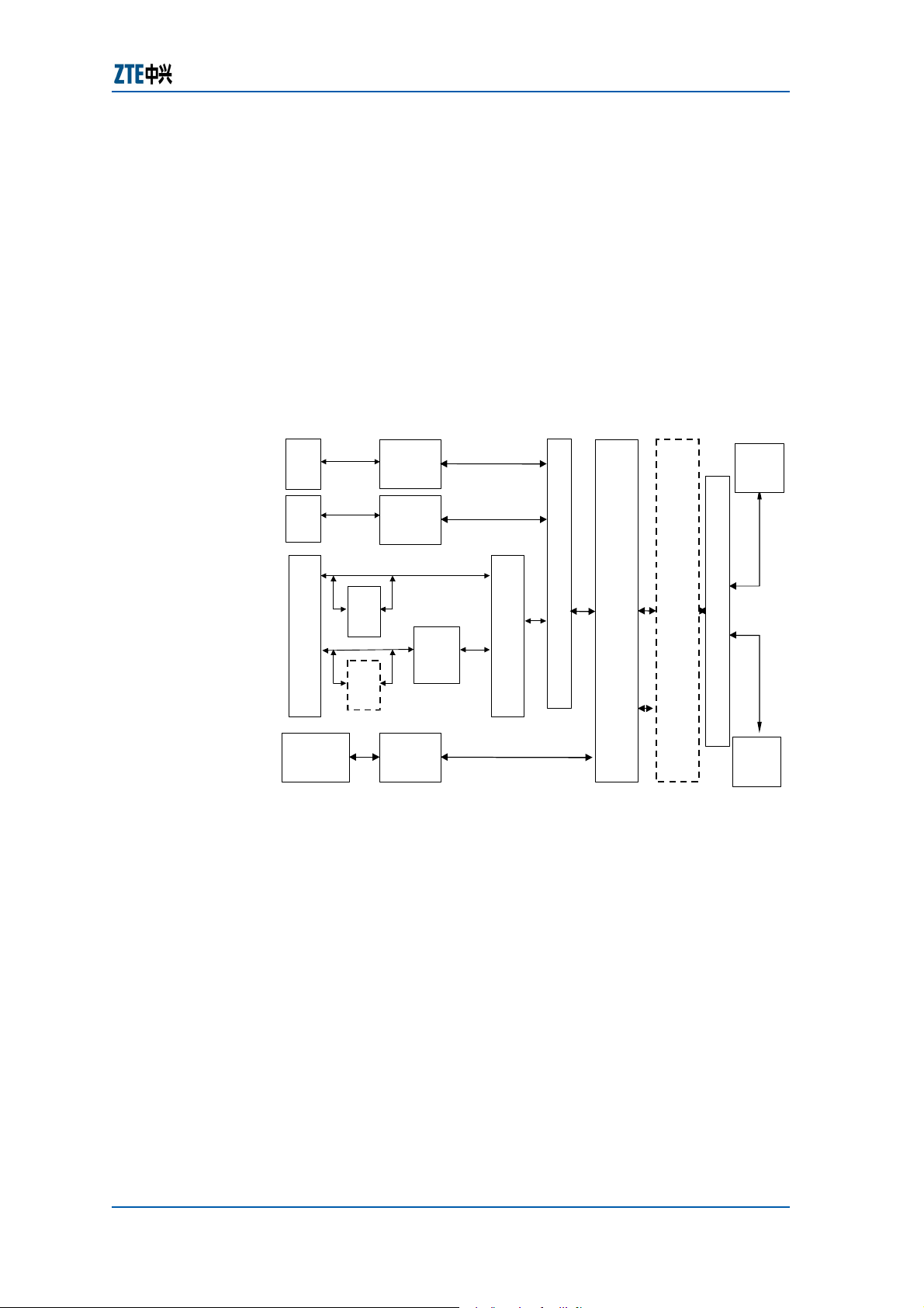
Figure 1 shows the function structure of the ZXA10 S300.
FIGURE 1 − ZXA10 S300 FUNCTIONAL STRUCTURE
PDH
interface
ATM
interface
Ethernet interface
STM-N interface
(Support
concatenation
POS interface )
L2
switch
L2
switch
TDM
mapping and
pre-
processing
ATM layer
processing
RPR MAC
processing
Physical layer
overhead
processing
layer
GFP/
LAPS/
HDLC
Multiplex and interface conversion
Service scheduling and core switching
(single-plane or double-plane)
Provide aggregate RPR interface
SDH or
POS
interface
Physical layer overhead processing
SDH or
POS
interface
THE ZXA10 S300 is based on the SDH technology. It implements
the processing and transmission of TDM, ATM and Ethernet
services at the same time, provides multiple service nodes under
a unified NMS, offers flexible multiple service scheduling and has
the capability of evolving into the next-generation network. It
provides the PDH, ATM, Ethernet and STM-N interfaces, as
shown in
Figure 2.
Confidential and Proprietary Information of ZTE CORPORATION 7

ZXA10 S300 (V1.1) Integrated Access Service Dispatching Unit Technical Manual
FIGURE 2 − ZXA10 S300 SCHEM ATIC DIAGRAM
PDH interface
STM-N interface
ATM interface
IS300
Ethernet interface
STM-N interface
STM-N interface
The ZXA10 S300 service capability: Provide a maximum of four
2.5 G SDH optical interfaces (dual system mode), and support
two 2.5 G SDH optical interfaces in the active/standby state;
four 622 M SDH optical interfaces, or 24 155 M SDH optical
interfaces, or the same-capacity mixture of 155 M and 622 M
SDH optical interfaces; support 4 × 63 E1 interfaces in each
single shelf; a maximum of 48 100 M interfaces and six GE
interfaces in the Ethernet interface, and 4,000 VLANs configured
in each ES board; 255 VLANs configured in each ESD board.
Capable of transmission and protection of the ATM service, and
support dynamic bandwidth adjustment in the RPR mode for the
Ethernet service.
TDM service
f Adopts standard SDH STM-N mapping multiplex structure
and provides PDH tributary interfaces (2 M).
f Provides standard STM-N interfaces and PDH (2 M)
interfaces, and supports multiple networking modes and
the interconnection of optical/electrical interfaces from
different manufacturers.
f Provides high-order/low-order cross-connect capabilities
of TDM services and supports 56 × 56 VC4-level highorder space division cross-connect and 1,008 × 1,008
VC12-level low-order time division cross-connect.
f Provides multiple types of networking and protection: 2.5
G/622 M/155 M 2-fiber unidirectional multiplex section
protection and 2.5G/622M/155 M 2-fiber path protection
ring. In addition, 2-fiber bi-directional multiplex section
protection ring and 4-fiber bi-directional multiplex section
protection ring will be provided in subsequent versions.
f Provides the orderwire function.
f Provides the timing input/output function.
f Provides the function of VC-4-level continuous
concatenation of high-order paths.
f Provides the function of automatic service configuration &
authentication by software through NMS.
Ethernet transparent transmission service
8 Confidential and Proprietary Information of ZTE CORPORATION
Chapter 1 Overview
The Ethernet service transparent transmission function
supported in the ZXA10 S300 means that any data frame
from an Ethernet interface need no Layer 2 switching and is
mapped to SDH Virtual Containers (VCs) immediately after
protocol encapsulation and rate adaptation. Then, these
frames are transmitted point-to-point via SDH nodes. The
functional block model is shown in
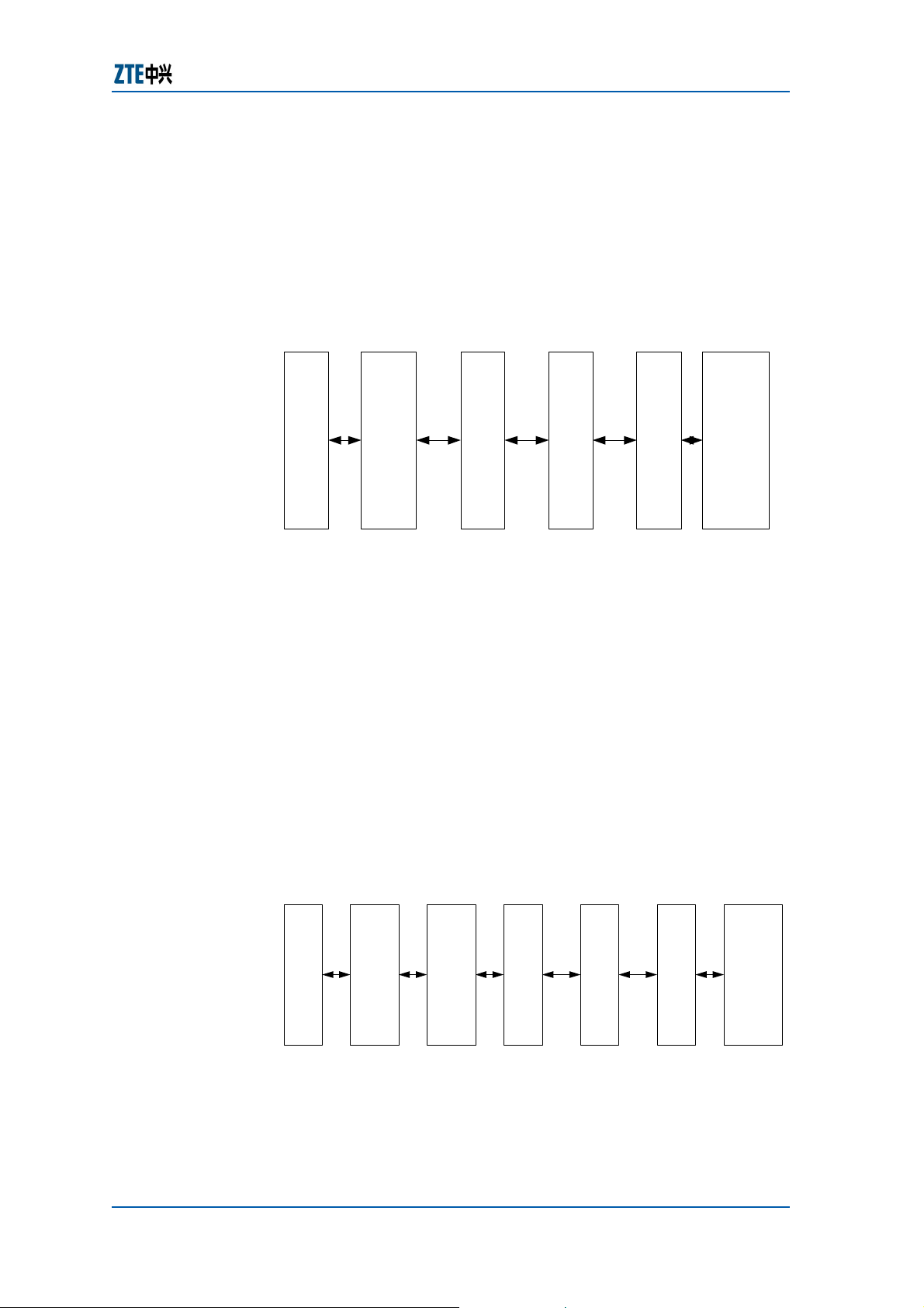
FIGURE 3 − ETHERNET SERVICE TRANSPARENT TRANSMISSION FUNCTION
MODEL OF THE ZXA10 S300
Figure 3.
Ethernet interfac e
GFP/
VC Mapping
Multiplex sectio n
processing
LAPS/
HDLC
Regenerato r section
processing
STM-N
interface
Assembly
The ZXA10 S300 has the following Ethernet service
transparent transmission functions:
f Configurable transmission link bandwidth.
f Ensured transparence of Ethernet services, including the
transparent transmission of Ethernet MAC frames and
VLAN tags.
Ethernet Layer 2 switching service
The Layer 2 switching function supported in the ZXA10 S300
refers to data packet switching based on Ethernet link layer
between multiple Ethernet user interfaces and one or more
standalone point-to-point links based on SDH virtual
containers. The functional block model is shown in
Figure 4.
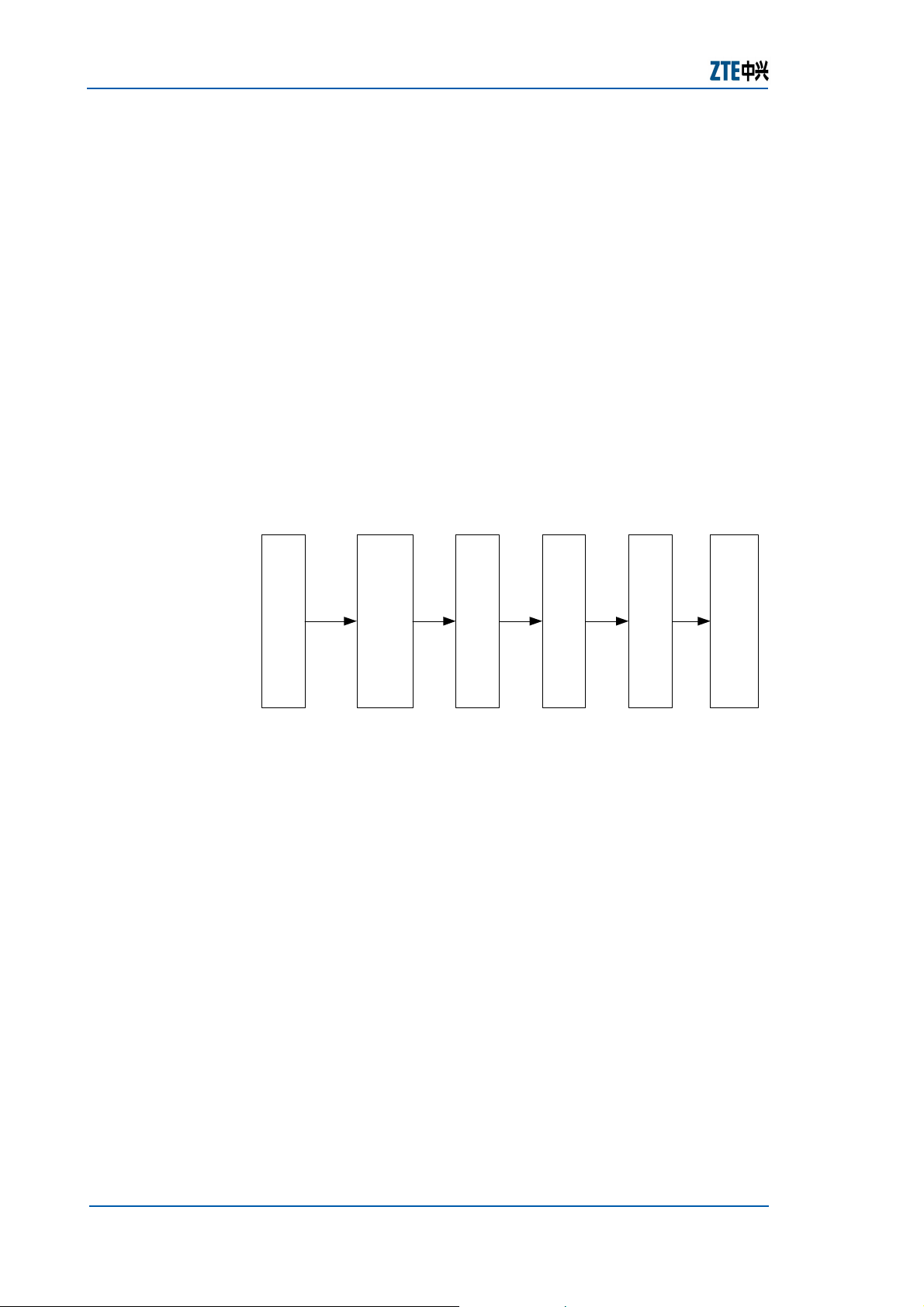
FIGURE 4 − ETHERNET L AYER 2 SWITCHING FUNCTION MODEL OF THE
ZXA10 S300
Ethernet interface
Layer-2 switching
GFP/
LAPS/
HDLC
Assembly
VC Mapping
Multiplex section
processing
Regenerator section
processing
interface
The ZXA10 S300 has the following Ethernet Layer 2
switching functions:
f Configurable transmission link bandwidth.
Confidential and Proprietary Information of ZTE CORPORATION 9
STM-N
ZXA10 S300 (V1.1) Integrated Access Service Dispatching Unit Technical Manual
f Ensured transparence of Ethernet services, including the
transparent transmission of Ethernet MAC frames and
VLAN tags.
f Implements the function of forwarding/filtering Ethernet
data frames, which complies with the IEEE802.1d
protocol.
f Provides two optional modes of self-learning and static
configuration to maintain the MAC address table.
f Supports flow control, including backpressure flow control
in half-duplex mode and IEEE802.3x flow control (also
called PAUSE frame control) function in full duplex mode.
ATM service
The ATM subsystem implements transmission, statistics
multiplex, VP/VC switching and VP protection of the ATM PVC
service, as shown in
FIGURE 5 − ATM FUNCTION SCHEM ATIC DIAGRAM
Figure 5.
ATM layer processing
ATM in terfa ce
VC Mapping
Multiplex section
Regenerator section
For lots of access equipment, the uplink interfaces are ATM
interfaces. The ZXA10 S300 serves as a multi-service access
platform. Due to the location of THE ZXA10 S300 in the
telecom network, the ATM has following features:
f Provides multi-layer reliability protection: Protection and
straight-through protection of the VPRING in the ATM
layer, the multiplex section in the SDH layer, or highorder channel.
f Guarantee the QOS and bandwidth for the service.
NM Functions
At the gateway Network Element (NE) (that is, the NE
connected to the NMS), the NE order wire control board
provides a 10 M/100 M Ethernet interface for connecting the
NMS server which provides Ethernet interface for managing
this NE. For the management of non-gateway NEs, the
massages transmitted from the NMS server to the gateway
NE are forwarded to the corresponding NEs by the network
management NE through ECC protocol stack. User defined
ECC protocol stack is adopted for the communication
between NEs. It includes four layers. At the physical layer,
STM-N interface
10 Confidential and Proprietary Information of ZTE CORPORATION

the DCC channel defined in the SDH frame structure is
adopted (D1~D3 and D4~D12 can be adopted and the
maximum available bandwidth reaches 768kbit/s). HDLC is
adopted at the link layer. At the network layer, a userdefined routing protocol is adopted, which is a simplified
version of OSPF. It adopts some routing principles of the
OSPF and provides fast route convergence function. At the
application layer, a user-defined message structure is
adopted to transmit the messages between the NEs. The ECC
protocol stack is applied to the 155 M, 622 M and 2.5 G
optical interfaces in THE ZXA10 S300. It can interwork with
the upgraded ECC protocol stack of the original built-in 155
M SDH device of ZXA10-AS1 and ZXA10-AS2.
Chapter 1 Overview
System Working Principle
The system working principle contains hardware principle and
software principle.
Hardware Principle
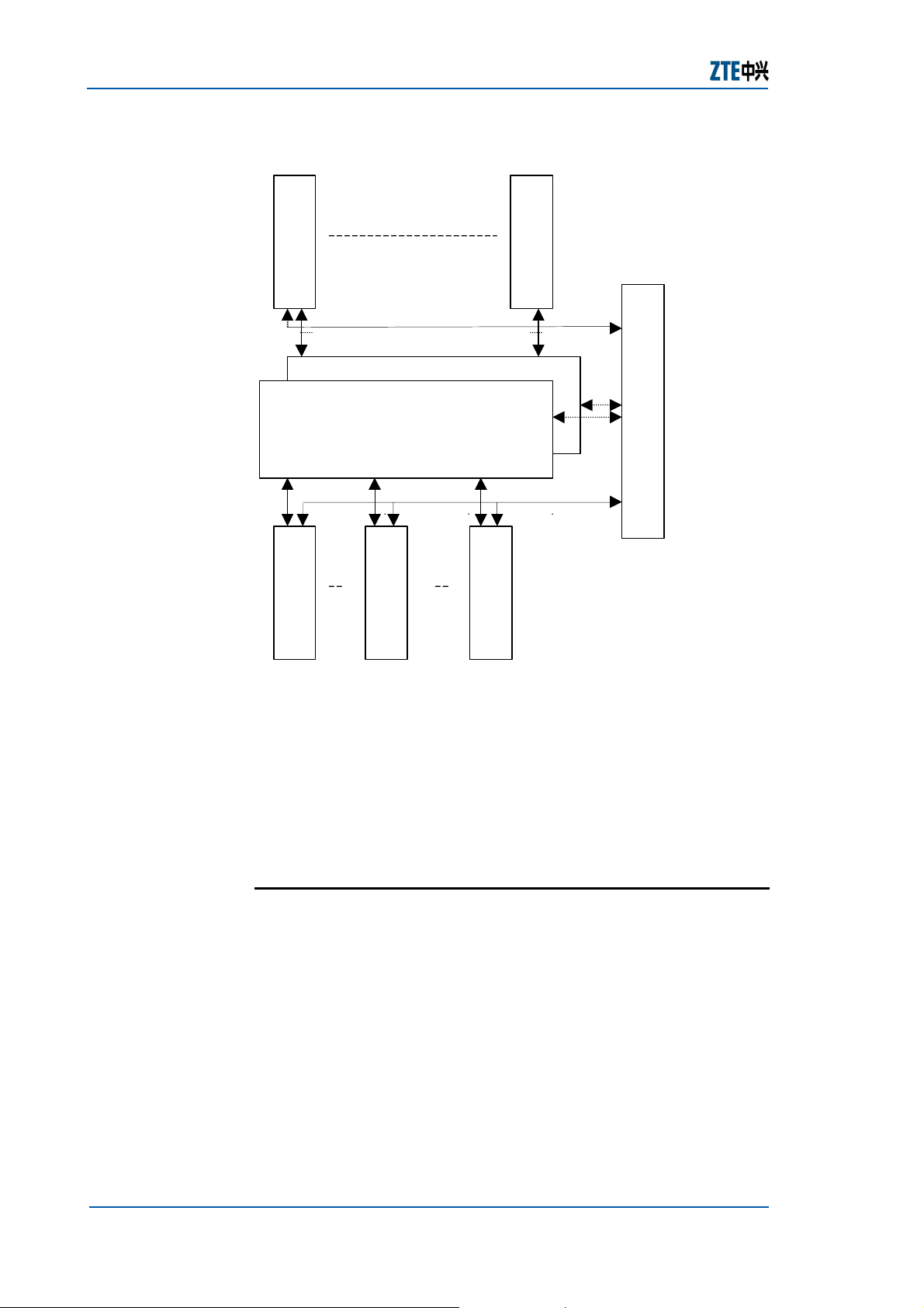
The overall hardware of the system is shown in Figure 6.
Confidential and Proprietary Information of ZTE CORPORATION 11
ZXA10 S300 (V1.1) Integrated Access Service Dispatching Unit Technical Manual
FIGURE 6 − SYSTEM H ARDWARE
SDH Line card
SDH Line card
NOWC board
TAA (standby) board
TAA (active) board
PDH Line card
ATM Line card
Ethernet Line
card
The cross-connect matrix is the core of the system. It
implements the add/drop of the services and the mixed
transmission of multiple services. It can do cross-connect with
four granularity levels: VC3, VC4, VC4-4C and VC12. An open
universal high-speed serial bus is used as the backplane bus for
the interconnection of cross-connect matrixes and line cards. It
supports mixed access of the Ethernet, ATM, and TDM.
Software Principle
The software system of THE ZXA10 S300 consists of three layers:
Transmission NMS SMN software (including the man-machine
interface and NMS server), NE order wire control board software
and line card software (including TAA board, TDM, ATM and EOS
line card).
From the view of NM, the software structure of the ZXA10 S300
is shown in
Figure 7.
12 Confidential and Proprietary Information of ZTE CORPORATION

FIGURE 7 − ZXA10 SOFTWARE STRUCTURE
Chapter 1 Overview
NM software
Man-machine interface
NM server
NS board software module
aggregation board
software module
Transmission
TDM
software
module
The NMS server implements the Manager function, the NE order
wire control board implements the Agent function, and various
line cards implement specific management actions.
The MNS server can communicate with the NE order wire control
board through the Ethernet interface or ECC protocol stack, thus
allowing the Manage to manage the Agent.
It does not directly send the message to the TAA board, TDM
line cards (including 2.5 G/622 M/155 M optical line boards, E1
electrical tributary board and 10M/100M Ethernet transparent
transmission board), ES line card and ATM line card.
The communication message between it and the line cards
should be processed and forwarded by the corresponding
module of the NE order wire control board.
The software module of the NE order wire control board saves
the software versions of all boards as well as all static
configuration databases in this NE.
??
????
EOS
software
S
????
module
ATM
AT
software
M
????
module
During the initialization after power-on, the function modules of
the NOWC board access the necessary static configuration data
in the data base module.
On the contrary, during the power-on and initialization, the line
cards first load the line card software from the Flash to the
SDRAM for running. Then the boards obtain the static data of
the line cards from the NE order wire control board.
Confidential and Proprietary Information of ZTE CORPORATION 13
ZXA10 S300 (V1.1) Integrated Access Service Dispatching Unit Technical Manual
Hardware Structure
This section introduces the overall system architecture and
board types.
Overall System Architecture
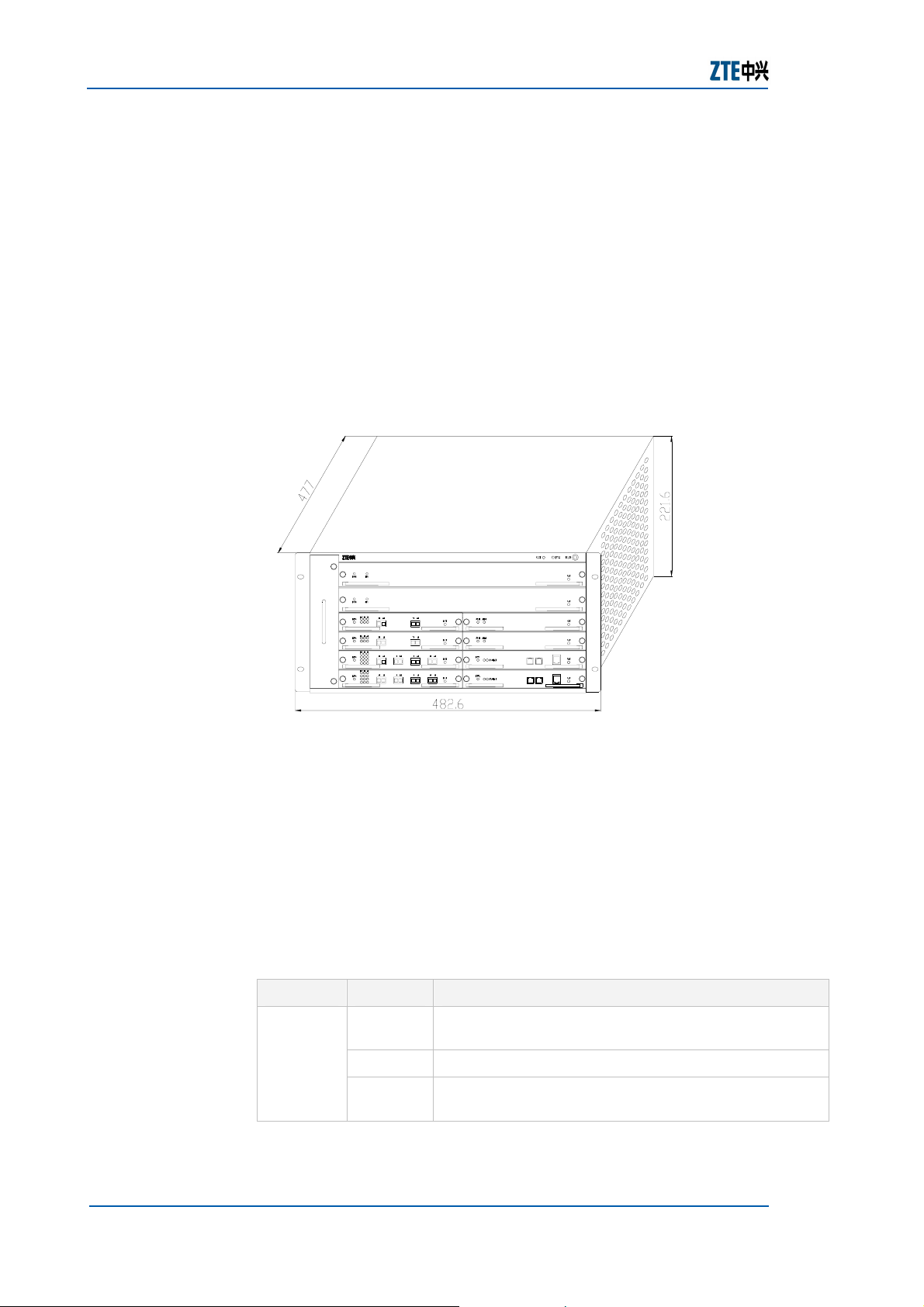
The ZXA10 S300 system has a standard plug-in box that is 19
inches wide and 5 U tall, as shown in
FIGURE 8 − STRUCTURE OF THE ZXA10 S300 PLUG-IN BOX
Figure 8.
ZXA10-IS300
TAA
FAN UNIT
TAA
OL16A
OL4A
OL1A
OL1A
E1C
E1C
ES
ES
Dimensions of the 5 U standard sub-rack: 221.6 mm × 482.6
mm × 477 mm (Height × Width × Depth).
The sub-rack has six layers with an opposite insertion structure.
Ten boards can be inserted into the front panel and six boards
can be inserted into the back panel. There are two indicators and
one ESD bonding point in the right bottom. The CST indicator is
the same as the RUN indicator of the NOWC board. The FTS
indicators indicate the temperature status of the fan. For details
of the FTS indicator, see
TABLE 4 − FTS INDICATION
Indicator State Indication
Table 4.
Off The NE is not powered on (or the NOWC board is not
in position).
FTS
Green Both the temperature and fans are normal.
Red The temperature is not at a normal level or the fans
become faulty.
14 Confidential and Proprietary Information of ZTE CORPORATION

Chapter 1 Overview
NOTE: The red light indicates that the current temperature is
not normal (the thermometer of any NE reads a temperature
higher than the threshold configured with the NMS that will
trigger the fans to run).
The first two layers are slots for the transport aggregation
boards: H1 and H2. Under the two layers are eight slots for line
cards. The four slots on the left side are respectively named A1,
A2, A3 and A4 from top down. The four on the right side are
respectively named B1, B2, B3 and B4 from top down. The PCI
and NOWC boards are respectively inserted to the first two slots
G1 and G2. The remaining four slots, B1L, B2L, B3L and B4L,
are used for line cards, corresponding to the line cards at the
front slots B1, B2, B3 and B4.
The peripherals of THE ZXA10 S300 includes: Cabinet, monomer
power supply, CSV, and user equipment.
If the P power supply is used, no monomer power supply is
required under the CSV. Otherwise, monomer power supply is
required under the CSV.
For the convenience of cabling, an 1 U cabling sub-rack is
required under the ZXA10 S300. All lead-out cables are routed
to the back of the cabinet via the cabling trough, are bound in
the binding beam, and finally are sent to user equipment, or go
out of the cabinet along the cabling components.
Board Types
The A10 S300 (V1.1) supports the boards below:
Standard LC interface STM-16 optical line board (OL16A)
Standard LC interface STM-1 optical line board (OL1A)
Standard LC interface STM-4 optical line board (OL4A)
63-channel E1 Tributary Card (E1C)
E1 unbalanced interface board (LIU)
E1 balanced interface board (LIB)
32-channel E1 tributary board (E1BU)
32-channel E1 balanced tributary board (E1BB)
Transmission aggregation board (TAA/TAAE/TAAED)
Network element order wire control board (NOWC)
Ethernet switching board
Ethernet leading-out board (ESL)
Ethernet transparent transmission board
Power clock interface board (PCI)
100 M Ethernet transparent transmission board (TFLA)
Confidential and Proprietary Information of ZTE CORPORATION 15

ZXA10 S300 (V1.1) Integrated Access Service Dispatching Unit Technical Manual
ATM switching board
RPR processing board
Ethernet ATM conversion board (EAT)
Software Structure
The software system of the ZXA10 S300 consists of five parts:
Software Module of NOWC Board
Software Module of Transmission Convergence Board
Software Module of TDM Line Card
Subsystem of EOS Software
Subsystem of RPR Software
Software Module of NOWC Board
During the initialization, the NOWC board first loads the
database from the Flash to the memory and configures it to the
corresponding modules and line cards. Meanwhile, it obtains the
time postmark of the static configuration data from the
transmission NMS SMN through the Ethernet interface or ECC
protocol stack. If the static configuration data in the NOWC Flash
is different from the postmark in the SMN, the NOWC software
will obtain the database with different time postmarks from the
SMN, write it into the Flash and reconfigure it to the modules
and line cards.
After storing the static configuration data of the whole NE, the
NOWC board software can work independent of the SMN. The
NOWC board software has various functions, including alarm
management, performance management, maintenance
management, database management, processing and forwarding
of the ECC messages and processing of order wire in the NE. The
module structure of the NOWC board software is shown in
9.
Figure
16 Confidential and Proprietary Information of ZTE CORPORATION
FIGURE 9 − MODULE S TRUCTURE OF NOWC B OARD SOFTWARE
Chapter 1 Overview
Database management module
management module
Maintenance
Alarm management
management module
module
Performance
System management
module
Order wire processing
module
Main control module
Operating system/ECC
protocol processing module
VxWroks
BSP
HardWare
The functions of the NOWC board software modules are
described as follows:
Main control module
f Implementing the initialization of the modules according
to their startup order.
f Implementing the database synchronization between the
NS board and the SMN during power-on.
f Distributing the messages between the Manager and
Agent through the QSDH
System management module
f Downloading the software version of the NOWC board,
standard structure.
TAA board and various line cards.
f Uploading, downloading and allocating the static
configuration database of the NE.
f Showing the software version number and version time
(including the NOWC board, TAA board and all line cards).
Showing the current running version area of the NS
board, version numbers of Area A/B NS boards, version
numbers of line cards of Area A/B and current running
version numbers of NS board and line cards.
f Setting the command for the NS board to restart the
version area.
f Configuring the NE time.
Alarm management module
Confidential and Proprietary Information of ZTE CORPORATION 17

ZXA10 S300 (V1.1) Integrated Access Service Dispatching Unit Technical Manual
f Detecting faults, and locating them in the line cards and
tributaries with an accuracy of one second.
f Reporting all alarm signals and relevant details.
f The alarm correlation, that is, when a higher-level alarm
is generated, the corresponding lower-level alarm should
be recovered. For example, the LOS alarm of the optical
interface board and the MS_AIS alarm of s4805.
f Implementing the alarm filter function, which can filter
the repeated and redundant alarms.
f Setting the alarm shielding function to shield the
detection of some alarms.
f Setting the levels of the faults.
f Reporting all or some alarms in the NE and the boards
and implementing the alarm synchronization function.
f The NS board and the line cards do not store the history
alarm data. The alarm time is marked by the SMN.
Performance management module
f Monitoring the performance of all NEs.
f Implementing 15-minute, one-day and 15 minute zero
counter performance data with an accuracy of one second.
f Setting 15-minute performance monitoring threshold and
one-day performance monitoring threshold, and reporting
one threshold exceeding event alarm in the current
counting period if the performance value exceeds this
threshold.
f The NS board and the line cards don not store the history
performance data.
Maintenance and management module
f SDH related maintenance functions
Forcing the software reset, hardware reset and
active/standby changeover of the NE core board (the
active/standby changeover can be configured with a time
parameter for automatic recover).
Forcing the software reset and hardware reset of the TDM
line card in the NE.
Querying the CPU occupancy of the NE core board and
the TDM line card.
Practicing the bidirectional multiplex section protection
and dual-node protection.
Line/terminal loopback (a time parameter can be
configured for automatic recovery)
Forcing error bit insertion (a time parameter can be
configured for automatic recovery)
18 Confidential and Proprietary Information of ZTE CORPORATION
 Loading...