

Page 1

ZXC10 CBTS
CDMA2000 Compact Base Transceiver
Station
Installation Manual
ZTE CORPORATION
ZTE Plaza, Keji Road South,
Hi-Tech Industrial Park,
Nanshan District, Shenzhen,
P. R. China
518057
Tel: (86) 755 26771900 800-9830-9830
Fax: (86) 755 26772236
URL: http://support.zte.com.cn
E-mail: doc@zte.com.cn
Page 2
LEGAL INFORMATION
Copyright © 2005 ZTE CORPORATION.
The contents of this document are protected by copyright laws and international treaties. Any reproduction or distribution of
this document or any portion of this document, in any form by any means, without the prior written consent of ZTE
CORPORATION is prohibited. Additionally, the contents of this document are protected by contractual confidentiality
obligations.
All company, brand and product names are trade or service marks, or registered trade or service marks, of ZTE
CORPORATION or of their respective owners.
This document is provided “as is”, and all express, implied, or statutory warranties, representations or conditions are
disclaimed, including without limitation any implied warranty of merchantability, fitness for a particular purpose, title or non-
infringement. ZTE CORPORATION and its licensors shall not be liable for damages resulting from the use of or reliance on
the information contained herein.
ZTE CORPORATION or its licensors may have current or pending intellectual property rights or applications covering the
subject matter of this document. Except as expressly provided in any written license between ZTE CORPORATION and its
licensee, the user of this document shall not acquire any license to the subject matter herein.
The contents of this document and all policies of ZTE CORPORATION, including without limitation policies related to support
or training are subject to change without notice.
Revision History
Date Revision No. Serial No. Description
04/04/2006 R1.0
sjzl20060563
CDMA2000 Compact Base Transceiver Station - English
Contents
Page 3
ZTE CORPORATION
Values Your Comments & Suggestions!
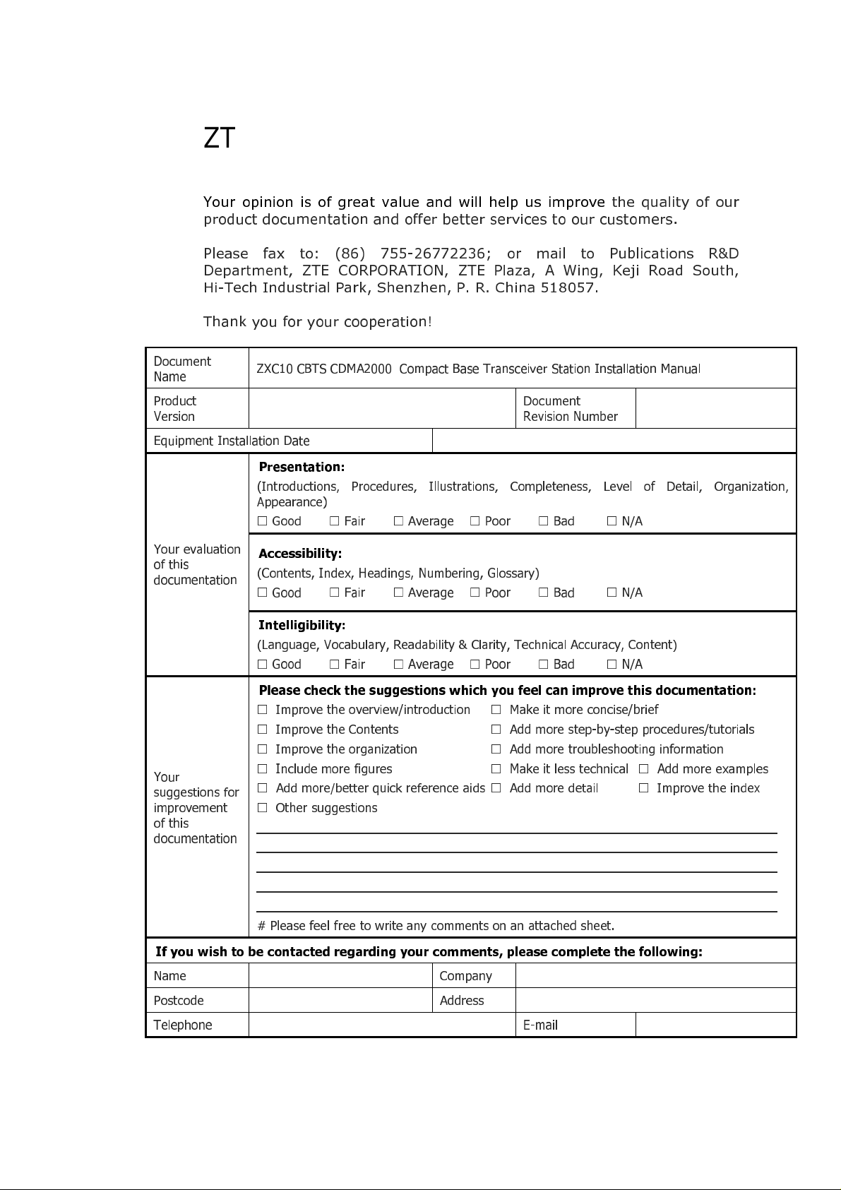
Your opinion is of great value and will help us improve the quality of our
product documentation and offer better services to our customers.
Please fax to: (86) 755-26772236; or mail to Publications R&D
Department, ZTE CORPORATION, ZTE Plaza, A Wing, Keji Road South,
Hi-Tech Industrial Park, Shenzhen, P. R. China 518057.
Thank you for your cooperation!
Document
Name
Product
Version
Equipment Installation Date
Your evaluation
of this
documentation
Your
suggestions for
improvement
of this
documentation
ZXC10 CBTS CDMA2000 Compact Base Transceiver Station Installation Manual
Presentation:
(Introductions, Procedures, Illustrations, Completeness, Level of Detail, Organization,
Appearance)
Good Fair Average Poor Bad N/A
Accessibility:
(Contents, Index, Headings, Numbering, Glossary)
Good Fair Average Poor Bad N/A
Intelligibility:
(Language, Vocabulary, Readability & Clarity, Technical Accuracy, Content)
Good Fair Average Poor Bad N/A
Please check the suggestions which you feel can improve this documentation:
Improve the overview/introduction Make it more concise/brief
Improve the Contents
Improve the organization
Include more figures
Add more/better quick reference aids Add more detail
Other suggestions
___________________________________________________________________________
___________________________________________________________________________
___________________________________________________________________________
___________________________________________________________________________
___________________________________________________________________________
# Please feel free to write any comments on an attached sheet.
Document
Revision Number
Add more step-by-step procedures/tutorials
Add more troubleshooting information
Make it less technical Add more examples
Improve the index
If you wish to be contacted regarding your comments, please complete the following:
Name Company
Postcode Address
Telephone E-mail
Page 4

This page is intentionally blank.
Page 5
Contents
About this Manual ...................................................................................xi
Purpose of this Manual ........................................................................................... xi
Typographical Conventions.....................................................................................xi
Mouse Operation Conventions................................................................................ xii
Safety Signs.........................................................................................................xiii
How to Get in Touch............................................................................................. xiv
Customer Support..............................................................................................................xiv
Documentation Support......................................................................................................xiv
Chapter 1.................................................................................... 15
Installation Preparation.........................................................................15
Hardware Installation Flow.....................................................................................16
CBTS Installation Precautions.................................................................................17
Environment Inspections.......................................................................................17
Installation Location Specifications .......................................................................................17
Temperature and Humidity Range.......................................................................................17
Power Supply Requirements................................................................................................18
Electromagnetic Radiation Protection....................................................................................18
Antenna Feeder System Requirements.................................................................................18
Other Accessory Devices.....................................................................................................19
Tool and Meter List for Installation..........................................................................19
Technical Documentation Preparation.....................................................................21
Project Commissioning Documents ......................................................................................21
Acceptance Reports............................................................................................................21
Reference Documents.........................................................................................................21
Chapter 2.................................................................................... 23
Unpacking and Handover.......................................................................23
Checking Equipment List .......................................................................................24
Unpacking Wooden Box.........................................................................................25
Unpacking Procedure..........................................................................................................25
Checking Cabinet................................................................................................................26
Unpacking Carton.................................................................................................26
Carton Structure.................................................................................................................26
Page 6

Unpacking Procedure..........................................................................................................26
Unpacking Precautions........................................................................................................27
Checking Boards.................................................................................................................27
Acceptance and Handover .....................................................................................27
Chapter 3.................................................................................... 29
Cabinet Installation................................................................................29
Cabinet Structure..................................................................................................30
Cabinet Installation Precautions..............................................................................31
Installation Location Specification...........................................................................31
Cabinet Installation Modes.....................................................................................32
Direct Installation Mode.........................................................................................33
Direct Installation Mode Flow...............................................................................................33
Direct Installation Mode Procedure.......................................................................................34
Adjustable Base Installation Mode ..........................................................................39
Adjustable Base Structure...................................................................................................40
Adjustable Base Installation Mode Flow ................................................................................41
Adjustable Base Installation Procedure.................................................................................42
Cabinet Accessories Installation...........................................................................................48
Cabling Runway .................................................................................................................48
CBTS Cabinet Interfaces........................................................................................49
Power Interface..................................................................................................................50
Feeder Cable Interface........................................................................................................50
E1/T1 Interfaces.................................................................................................................51
FE Interfaces......................................................................................................................51
Room Monitoring Interface..................................................................................................52
Order Wire Phone Interface.................................................................................................52
Power Monitoring Interface..................................................................................................53
External BDS Interface........................................................................................................53
External Monitoring Interface...............................................................................................54
GPS Interface.....................................................................................................................54
Chapter 4.................................................................................... 55
Cable Installation...................................................................................55
Power and Grounding Cables.................................................................................56
Power Cable Types.............................................................................................................56
Power Cable Preparation.....................................................................................................56
Power and Grounding Cable Connections..............................................................................57
Cable Installation Requirements...........................................................................................58
Trunk Cable Installation.........................................................................................60
T1 Cable Installation...........................................................................................................60
E1 Cable Installation...........................................................................................................61
Page 7
Trunk Cable Processing.......................................................................................................64
Trunk Cable Conversion ......................................................................................................66
E1/T1 Cable Installation Requirements.................................................................................68
Feeder cable installation......................................................................................................69
Chapter 5.................................................................................... 71
Monitoring System Installation..............................................................71
Smog Sensor Installation.......................................................................................72
Installation Procedure.........................................................................................................72
Terminal Connections .........................................................................................................73
Temperature and Humidity Sensor Installation........................................................73
Installation Procedure.........................................................................................................73
Terminal Connections .........................................................................................................75
Installation Precautions.......................................................................................................75
Infrared Sensor Installation....................................................................................75
External Monitoring Cable Installation.....................................................................77
Chapter 6.................................................................................... 79
Main Antenna Feeder System Installation.............................................79
Main Antenna System Installation ..........................................................................80
Antenna Installation Preparation..........................................................................................80
Antenna Installation Precautions..........................................................................................80
Main Antenna Feeder System Structure................................................................................80
Antenna Installation Technical Parameters............................................................................82
Antenna Installation Flow Chart...........................................................................................83
Selecting Installation Position...............................................................................................83
Moving and Hoisting Antenna ..............................................................................................83
Uni-Directional Antenna Installation.....................................................................................85
Omni-Directional Antenna Installation ..................................................................................87
Main Feeder Installation.........................................................................................88
Feeder Window Installation.................................................................................................89
Feeder Connector Preparation..............................................................................................90
Feeder Cutting ...................................................................................................................93
Jumper Installation.............................................................................................................93
Waterproofing Joints...........................................................................................................94
Feeder Grounding Clip Installation........................................................................................95
Routing Feeders.................................................................................................................96
Hoisting Feeders to Tower...................................................................................................97
CBTS Grounding System.....................................................................................................99
Grounding Principles.........................................................................................................100
Grounding Copper Busbar Installation................................................................................100
Lightning Arrester Installation............................................................................................101
Page 8
Routing Feeders into Equipment Room...............................................................................102
Chapter 7.................................................................................. 105
GPS Antenna Feeder System Installation............................................105
GPS Antenna Feeder System Structure.................................................................106
Installation Position and Requirements..................................................................107
Installation Requirements..................................................................................................108
Lightning Protection Requirements.....................................................................................109
NJ-9 Connector Preparation .................................................................................109
NJ-9 Connector ................................................................................................................109
Connector Preparation Procedure....................................................................................... 110
GPS Connector Installation check.......................................................................................115
Chapter 8.................................................................................. 117
Board Installation.................................................................................117
Installation Flow Chart.........................................................................................118
Installation Procedure and Precautions..................................................................119
CTSB Board Slot...............................................................................................................119
RFS Board Installation.......................................................................................................120
BDS Board Installation......................................................................................................121
Installation Precautions.....................................................................................................122
Chapter 9.................................................................................. 123
Hardware Installation Check ...............................................................123
Cabinet Installation Check...................................................................................124
Cabling Rack Installation Check............................................................................124
Cable Installation Check ......................................................................................125
Power and Grounding Cables.............................................................................................125
Trunk and RF Cables.........................................................................................................126
Board and Sensor Installation Check.....................................................................126
Antenna and GPS Feeder System Installation Check ..............................................127
1/2” Indoor Jumper..........................................................................................................127
Lightning arrester.............................................................................................................127
Main GPS Feeder..............................................................................................................127
Feeder Window and Waterproof Curve ...............................................................................128
Three – Way Feeder Clamp...............................................................................................128
1/2” Outdoor Jumper........................................................................................................129
Antenna...........................................................................................................................129
Feeder SWR.....................................................................................................................130
Environment Check.............................................................................................130
Chapter 10................................................................................ 131
Power On and Off Mechanism..............................................................131
Page 9

Power Supply Inspection .....................................................................................132
Power-on Procedure............................................................................................133
First Time Power-on..........................................................................................................133
Normal Power-on.............................................................................................................133
Power-off Procedure............................................................................................133
Appendix A ............................................................................... 135
Packing, Storage and Transportation ..................................................135
Packaging ..........................................................................................................136
Cabinet packing................................................................................................................136
Cabinet Packing Procedure................................................................................................137
Board Packing..................................................................................................................139
Board packing procedure...................................................................................................139
Base Packing....................................................................................................................144
Engineering Materials Packing............................................................................................144
Transportation....................................................................................................144
Storage..............................................................................................................145
Appendix B ............................................................................... 147
SiteMaster Usage..................................................................................147
Frequency Range Selection..................................................................................148
SiteMaster Check................................................................................................148
Feeder Input Parameters.....................................................................................148
Tester Installation...............................................................................................149
Measuring SWR ..................................................................................................149
Measuring DTF ...................................................................................................150
Appendix C ............................................................................... 151
Cabinet Working Modes .......................................................................151
Appendix D............................................................................... 153
Monitoring Cables Definition................................................................153
Acronyms.................................................................................. 157
Figures...................................................................................... 159
Tables....................................................................................... 163
Index ........................................................................................ 165
Page 10

This page is intentionally blank.
Page 11
About this Manual
Purpose of this Manual
This manual describes ZXC10 Compact Base Transceiver Station
hardware installation.
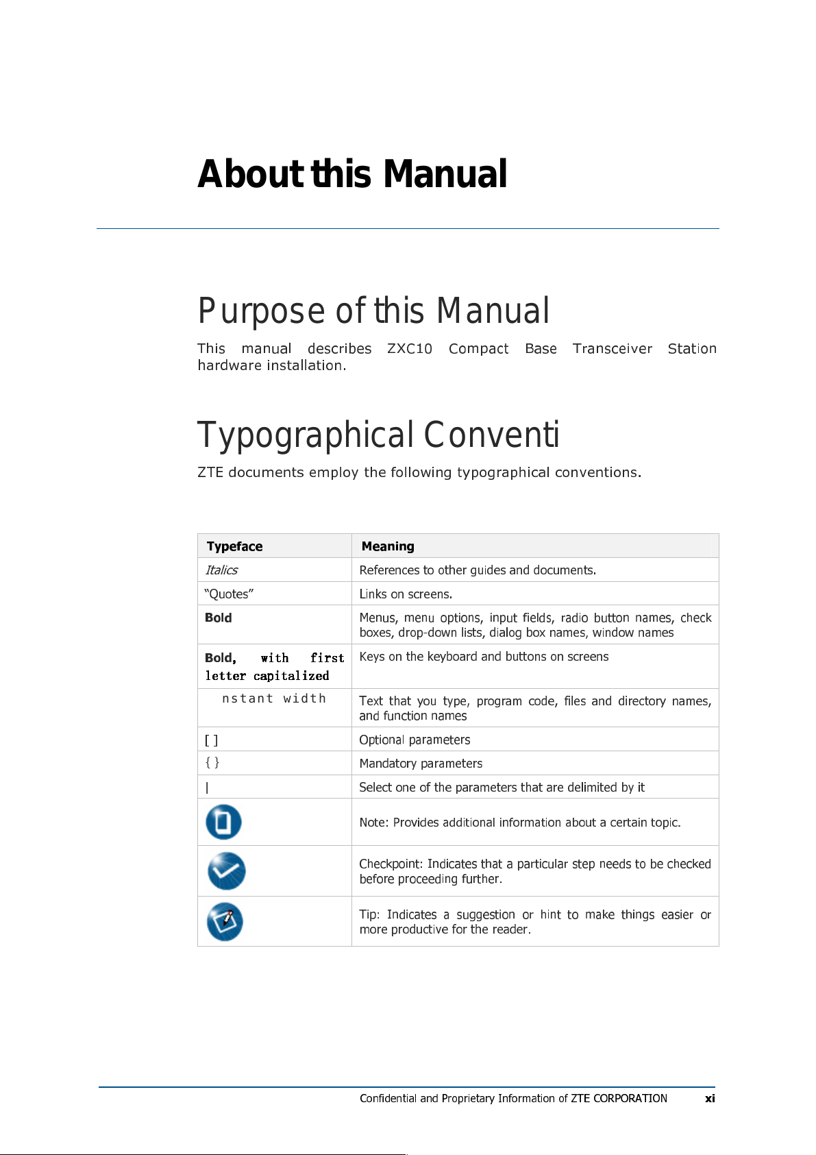
Typographical Conventions
ZTE documents employ the following typographical conventions.
TAB LE 1 - T YP OGR AP HI CAL CO NVE N TIO N S
Typeface Meaning
Italics
“Quotes” Links on screens.
Bold
Bold
, with first
, with first
, with first , with first
letter capitalized
letter capitalized
letter capitalizedletter capitalized
Constan t widt h
[ ] Optional parameters
{ }
| Select one of the parameters that are delimited by it
References to other guides and documents.
Menus, menu options, input fields, radio button names, check
boxes, drop-down lists, dialog box names, window names
Keys on the keyboard and buttons on screens
Text that you type, program code, files and directory names,
and function names
Mandatory parameters
Note: Provides additional information about a certain topic.
Checkpoint: Indicates that a particular step needs to be checked
before proceeding further.
Tip: Indicates a suggestion or hint to make things easier or
more productive for the reader.
Confidential and Proprietary Information of ZTE CORPORATION
xi
Page 12
ZXC10 CBTS I2 Installation Manual
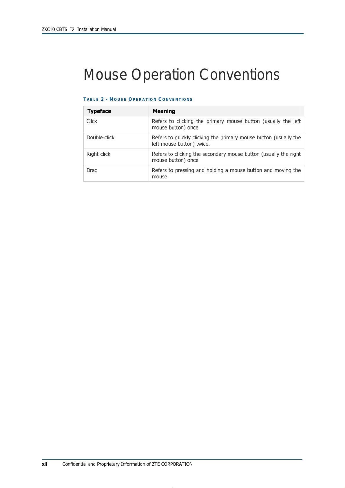
Mouse Operation Conventions
TAB LE 2 - M OUSE O PE RAT I ON CON VEN TI ON S
Typeface Meaning
Click Refers to clicking the primary mouse button (usually the left
Double-click Refers to quickly clicking the primary mouse button (usually the
Right-click Refers to clicking the secondary mouse button (usually the right
Drag Refers to pressing and holding a mouse button and moving the
mouse button) once.
left mouse button) twice.
mouse button) once.
mouse.
xii
Confidential and Proprietary Information of ZTE CORPORATION
Page 13
About this Manual
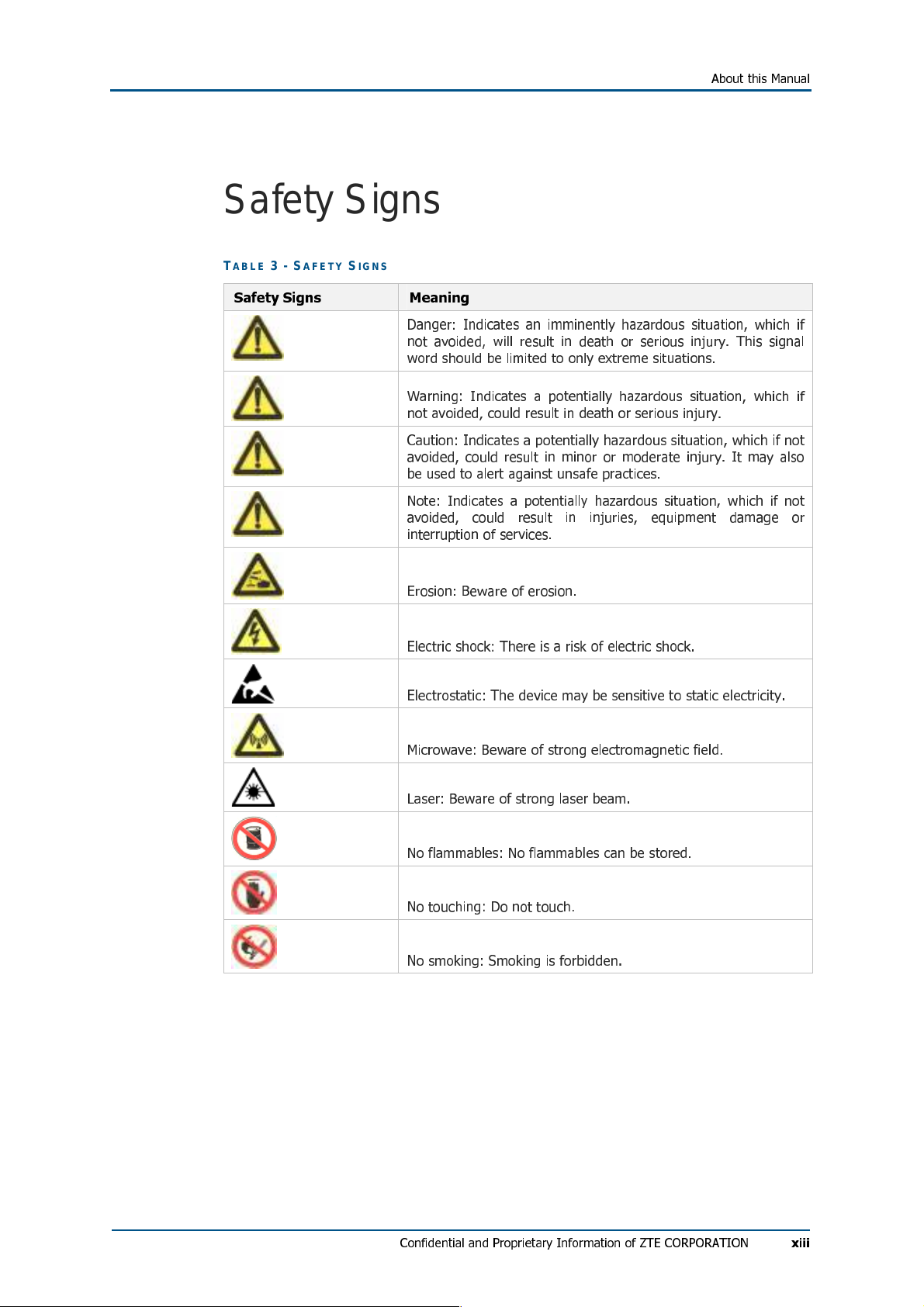
Safety Signs
TAB LE 3 - S AF ETY SIGN S
Safety Signs Meaning
Danger: Indicates an imminently hazardous situation, which if
not avoided, will result in death or serious injury. This signal
word should be limited to only extreme situations.
Warning: Indicates a potentially hazardous situation, which if
not avoided, could result in death or serious injury.
Caution: Indicates a potentially hazardous situation, which if not
avoided, could result in minor or moderate injury. It may also
be used to alert against unsafe practices.
Note: Indicates a potentially hazardous situation, which if not
avoided, could result in injuries, equipment damage or
interruption of services.
Erosion: Beware of erosion.
Electric shock: There is a risk of electric shock.
Electrostatic: The device may be sensitive to static electricity.
Microwave: Beware of strong electromagnetic field.
Laser: Beware of strong laser beam.
No flammables: No flammables can be stored.
No touching: Do not touch.
No smoking: Smoking is forbidden.
Confidential and Proprietary Information of ZTE CORPORATION
xiii
Page 14

ZXC10 CBTS I2 Installation Manual
How to Get in Touch
The following section provides information on how to obtain support for
the documentation and the software.
Customer Support
If you have problems, questions, comments, or suggestions regarding
your product, contact us by e-mail at support@zte.com.cn. You can also
call our customer support center at (86) 755 26771900 and (86) 800-
9830-9830.
Documentation Support
ZTE welcomes your comments and suggestions on the quality and
usefulness of this document. For further questions, comments, or
suggestions on the documentation, you can contact us by e-mail at
doc@zte.com.cn; or you can fax your comments and suggestions to (86)
755 26772236. You can also explore our website at
http://support.zte.com.cn, which contains various interesting subjects like
documentation, knowledge base, forum and service request.
FCC STATEMENT
Before using this CDMA ZXC10 CBTS I28A and CBTS I219, read this
important RF energy awareness and control information and operational
instructions to ensure compliance with the FCC RF exposure guidelines.
NOTICE: Working with the equipment while in operation, may expose the
technician to RF electromagnetic fields that exceed FCC rules for human
exposure. Visit the FCC website at www.fcc.gov/oet/rfsafety to learn more
about the effects of exposure to RF electromagnetic fields.
Changes or modifications to this unit not expressly approved by the party
responsible for compliance will void the user’s authority to operate the
equipment. Any change to the equipment will void FCC grant.
This equipment has been tested and found to comply with the limits for a
Class A digital device, pursuant to the FCC Rules. This equipment
generates, uses and can radiate radio frequency energy and, if not
installed and used in accordance with the instructions, may cause harmful
interference to radio communications. However, there is no guarantee that
xiv
interference will not occur in a particular installation.
Confidential and Proprietary Information of ZTE CORPORATION
Page 15
Cha p t e r 1
Installation Preparation
This chapter describes:
Hardware installation flow
CBTS installation precautions
Environment inspections
Installation location specifications
Temperature and humidity requirements
Power supply requirements
Electromagnetic radiation protection
Antenna feeder system requirements
Other accessory devices
Tool and meter list for installation
Technical documentation preparation
Project commissioning documents
Acceptance reports
Reference documents
Confidential and Proprietary Information of ZTE CORPORATION
15
Page 16
ZXC10 CBTS I2 Installation Manual
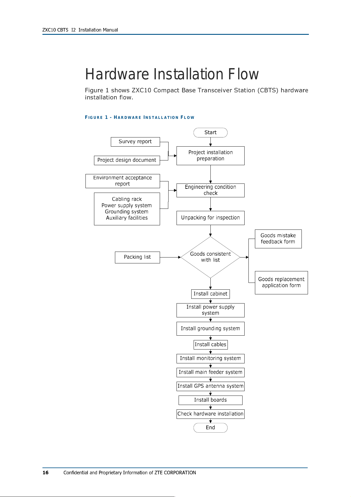
Hardware Installation Flow
Figure 1 shows ZXC10 Compact Base Transceiver Station (CBTS) hardware
installation flow.
FIG UR E 1 - HARD WARE I NS TAL L ATI O N FL OW
16
Confidential and Proprietary Information of ZTE CORPORATION
Page 17
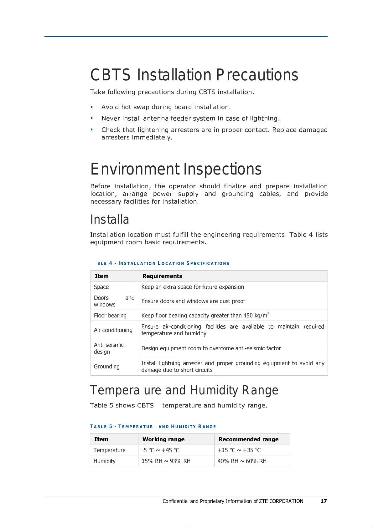
CBTS Installation Precautions
Take following precautions during CBTS installation.
Avoid hot swap during board installation.
Never install antenna feeder system in case of lightning.
Check that lightening arresters are in proper contact. Replace damaged
arresters immediately.
Environment Inspections
Before installation, the operator should finalize and prepare installation
location, arrange power supply and grounding cables, and provide
necessary facilities for installation.
Installation Location Specifications
Installation location must fulfill the engineering requirements. Table 4 lists
equipment room basic requirements.
TAB LE 4 - INST AL L ATI O N LO CATI ON SPE CIFI CATI ON S
Item Requirements
Space Keep an extra space for future expansion
Doors and
windows
Floor bearing Keep floor bearing capacity greater than 450 kg/m
Air conditioning
Anti-seismic
design
Grounding
Ensure doors and windows are dust proof
2
Ensure air-conditioning facilities are available to maintain required
temperature and humidity
Design equipment room to overcome anti-seismic factor
Install lightning arrester and proper grounding equipment to avoid any
damage due to short circuits
Temperature and Humidity Range
Table 5 shows CBTS temperature and humidity range.
TAB LE 5 - TEM PER AT U RE AN D HU MI DI TY R ANG E
Item Working range Recommended range
Temperature -5 °C ~ +45 °C +15 °C ~ +35 °C
Humidity 15% RH ~ 93% RH 40% RH ~ 60% RH
Confidential and Proprietary Information of ZTE CORPORATION
17
Page 18

ZXC10 CBTS I2 Installation Manual
Power Supply Requirements
Table 6 illustrates ZXC10 CBTS power supply requirements under normal
operation.
TAB LE 6 - POWE R SUPP L Y INDI CE S
Indices Name Index Requirements
DC power
supply
AC power
supply
Power system
range
Power noise level
Power protection
Power system
range
Power noise level
Power protection
-48 V power supply in range of -43.2 V ~ -56.5 V
Satisfies Ministry of Post and Telecom technical
specifications
Includes Over-voltage/Over-current protection and
indication
110 V power supply in range of 85 V ~ 135 V
220 V power supply in range of 150 V ~ 300 V
Satisfies Ministry of Post and Telecom technical
specifications
Includes Over-voltage/Over-current protection and
indication
Electromagnetic Radiation Protection
Table 7 shows electromagnetic radiation protection requirements.
TAB LE 7 - R AD IAT I ON P RO TEC TI ON R EQU I REM E NTS
Item Requirements
In 24 hours of a day, average value of electromagnetic power density
Public exposure
(in six consecutive minutes) should be less than 0.4 W/m2 (30 MHz ~
3000 MHz)
18
Professional
radiation
In 8 hours of a day, average value of electromagnetic power density (in
six consecutive minutes) should be less than 2 W/m2 (30 MHz ~ 3000
MHz)
Antenna Feeder System Requirements
Check whether following items comply with CBTS requirements and
project design.
Height and dimensions of feeder window
Height, weight bearing and grounding of outdoor cable rack
Height, weight bearing and grounding of indoor cable rack
Height, diameter, weight bearing, wind resisting, grounding, lightning
protection, and direction of antenna installation pole of building BS
Height, diameter, weight bearing, wind resisting, grounding, lightning
protection, and direction of antenna installation pole of iron tower BS
Confidential and Proprietary Information of ZTE CORPORATION
Page 19
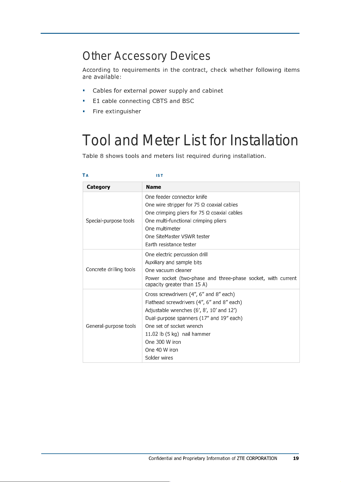
Other Accessory Devices
According to requirements in the contract, check whether following items
are available:
Cables for external power supply and cabinet
E1 cable connecting CBTS and BSC
Fire extinguisher
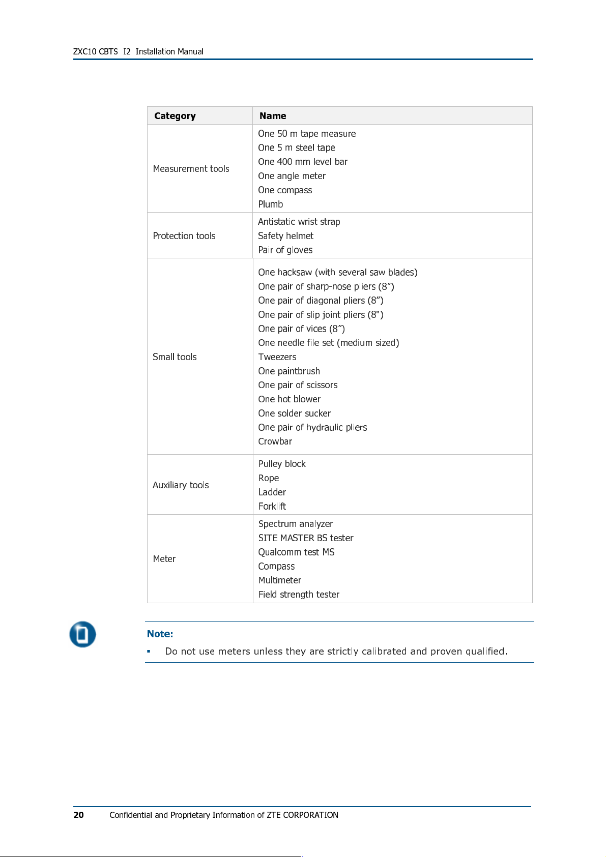
Tool and Meter List for Installation
Table 8 shows tools and meters list required during installation.
TAB LE 8 - TOO L AN D MET ER LIS T
Category Name
Special-purpose tools
Concrete drilling tools
General-purpose tools
One feeder connector knife
One wire stripper for 75 Ω coaxial cables
One crimping pliers for 75 Ω coaxial cables
One multi-functional crimping pliers
One multimeter
One SiteMaster VSWR tester
Earth resistance tester
One electric percussion drill
Auxiliary and sample bits
One vacuum cleaner
Power socket (two-phase and three-phase socket, with current
capacity greater than 15 A)
Cross screwdrivers (4”, 6” and 8” each)
Flathead screwdrivers (4”, 6” and 8” each)
Adjustable wrenches (6’, 8’, 10’ and 12’)
Dual-purpose spanners (17” and 19” each)
One set of socket wrench
11.02 lb (5 kg) nail hammer
One 300 W iron
One 40 W iron
Solder wires
Confidential and Proprietary Information of ZTE CORPORATION
19
Page 20
ZXC10 CBTS I2 Installation Manual
Category Name
Measurement tools
Protection tools
Small tools
One 50 m tape measure
One 5 m steel tape
One 400 mm level bar
One angle meter
One compass
Plumb
Antistatic wrist strap
Safety helmet
Pair of gloves
One hacksaw (with several saw blades)
One pair of sharp-nose pliers (8”)
One pair of diagonal pliers (8”)
One pair of slip joint pliers (8")
One pair of vices (8”)
One needle file set (medium sized)
Tweezers
One paintbrush
One pair of scissors
One hot blower
One solder sucker
One pair of hydraulic pliers
Crowbar
Pulley block
Auxiliary tools
Rope
Ladder
Forklift
Spectrum analyzer
SITE MASTER BS tester
Meter
Qualcomm test MS
Compass
Multimeter
Field strength tester
Note:
Do not use meters unless they are strictly calibrated and proven qualified.
20
Confidential and Proprietary Information of ZTE CORPORATION
Page 21

Technical Documentation
Preparation
Project Commissioning Documents
Prepare following technical documents for equipment commissioning
Project Survey Report
Engineering staff should prepare a Project Survey Report during onsite
survey.
Engineering design documents
Engineering design documents should be completed by designing unit
that the subscriber entrusts. Its duplication copy should be provided to
the equipment provider before equipment delivery.
Environment Acceptance Report
Environment Acceptance Report
acceptance in BSC survey, showing whether CBTS installation
requirements are satisfied. If installation environment is not
appropriate, the customer should improve the conditions and solve the
problems. Conduct second environment inspection before the
engineering starts.
is used for first environment
Acceptance Reports
Installation Acceptance Report
commissioning acceptance documents. The equipment supplier provides
these documents to the customer at delivery time. The installation staff
should complete these documents in presence of the customer after CBTS
system commissioning.
and
Test Acceptance Report
are post
Reference Documents
Use following manuals for reference during installation:
ZXC10 Compact Base Transceiver Station Installation Manual
ZXC10 Compact Base Transceiver Station Technical Manual
ZXC10 Compact Base Transceiver Station Hardware Manual
Confidential and Proprietary Information of ZTE CORPORATION
21
Page 22

ZXC10 CBTS I2 Installation Manual
This page is intentionally blank.
22
Confidential and Proprietary Information of ZTE CORPORATION
Page 23

Cha p t e r 2
Unpacking and Handover
This chapter describes:
Checking equipment list
Unpacking wooden case
Unpacking procedure
Checking cabinet
Unpacking carton
Carton structure
Unpacking procedure
Unpacking precautions
Checking boards
Acceptance and handover
Confidential and Proprietary Information of ZTE CORPORATION
23
Page 24
ZXC10 CBTS I2 Installation Manual
Checking Equipment List
Count goods during unpacking and note following points:
Check
Check total number of goods, intactness of packing boxes, and check
whether arrival place is actual installation place against packing list
number attached to packing boxes.
If goods are intact, start to unpack and inspect them.
Contact ZTE headquarters, if any item is damaged or missing during
unpacking inspection process.
Use appropriate tools to open cartons to avoid any equipment damage.
Note
Handle CBTS equipment with care and protect it from direct sunlight and rain.
Count goods against attached list and keep a record.
Delivery Checklist
:
of ZTE CORPORATION.
24
Confidential and Proprietary Information of ZTE CORPORATION
Page 25
Unpacking Wooden Box
Unpacking Procedure
Take following steps to unpack a wooden box:
1. Arrange appropriate tools such as nail hammer, pliers, straight
screwdriver and crowbar.
2. Insert a flat-tip screwdriver into slit between case and front cover
board to make it loose. Then insert a crowbar to unclench cover board.
3. Erect wooden case. Make sure that supports are at the bottom and pull
cabinet out from case gently.
4. Remove packing adhesive cabinet tape.
Note:
Handle CBTS cabinet with care during movement to avoid damage.
Confidential and Proprietary Information of ZTE CORPORATION
25
Page 26
ZXC10 CBTS I2 Installation Manual
Checking Cabinet
Check cabinet according to p
There are no dents, bulges, scratches, peels, blithers, blisters or
smudges on outer surface of cabinets.
Busbars, fans and installation positions on cabinets are free from
damage or distortion.
Cabinet slots for plug-in frames are intact. Guide rails of plug-in slots
are not damaged.
Installation slot labels are intact.
Fastening screws are not loosen, disconnected, or mistakenly placed.
Accessories and fittings needed for cabinet installation are complete.
acking list and
ensure following:
Unpacking Carton
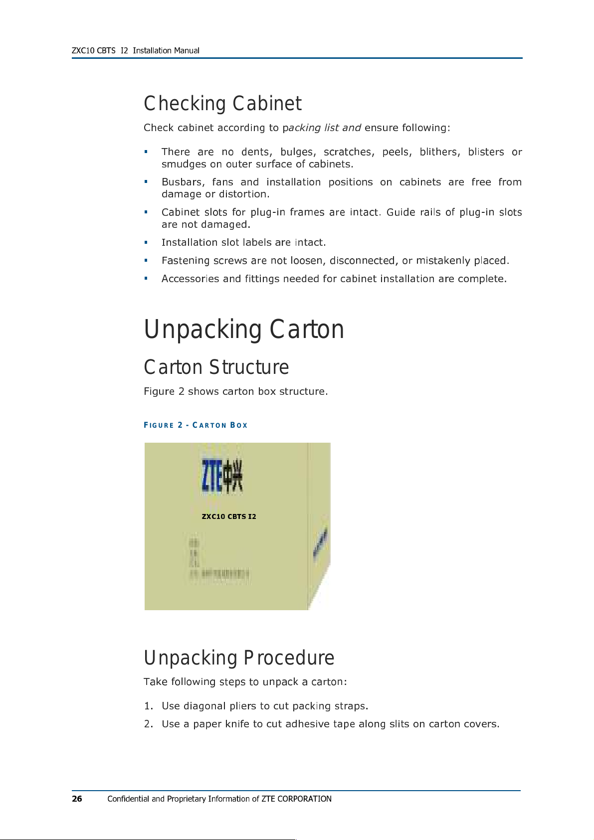
Carton Structure
Figure 2 shows carton box structure.
FIG UR E 2 - CART ON BOX
ZXC10 CBTS I2
Unpacking Procedure
Take following steps to unpack a carton:
1. Use diagonal pliers to cut packing straps.
26
2. Use a paper knife to cut adhesive tape along slits on carton covers.
Confidential and Proprietary Information of ZTE CORPORATION
Page 27

Unpacking Precautions
Take following precautions to unpack carton:
Take anti-static measures to avoid equipment damage.
To avoid damage to goods, do not cut too deep.
Wait for 30 minutes before unpacking equipment, when equipment is
moved from a colder and drier place to a hotter and damper place.
Properly recycle desiccants.
Checking Boards
Check quality, quantity, type, cracks and model of all boards inside carton
against packing list provided by ZTE office.
Acceptance and Handover
Upon completion of unpacking, representative of customer and project
supervisor should sign
acceptance. Each party should have a copy of
Report.
Unpacking for Inspection Report
Unpacking for Inspection
to acknowledge
Confidential and Proprietary Information of ZTE CORPORATION
27
Page 28

ZXC10 CBTS I2 Installation Manual
This page is intentionally blank.
28
Confidential and Proprietary Information of ZTE CORPORATION
Page 29
Cha p t e r 3
Cabinet Installation
This chapter describes:
Cabinet structure
Cabinet installation precautions
Installation location specification
Cabinet installation modes
Direct installation
Direct installation mode flow
Direct installation mode procedure
Adjustable base installation
Adjustable base structure
Adjustable base installation mode flow
Adjustable base installation procedure
Cabinet accessories installation
Cabling runway
CBTS cabinet interfaces
Power interface
Feeder cable interface
E1 and T1 cable interface
FE cable interface
Room monitoring interface
Order wire phone interface
Power monitoring interface
External BDS interface
External monitoring interface
GPS cable interface
Confidential and Proprietary Information of ZTE CORPORATION
29
Page 30
ZXC10 CBTS I2 Installation Manual
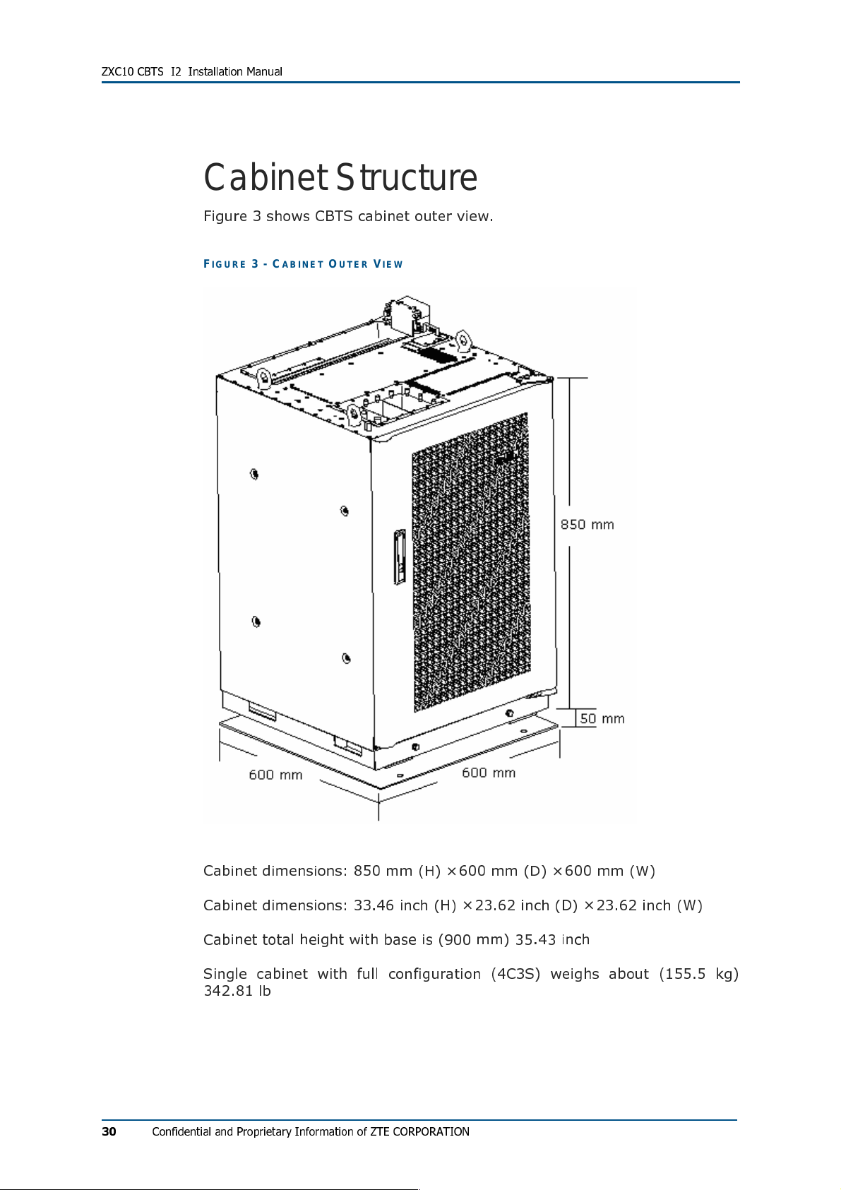
Cabinet Structure
Figure 3 shows CBTS cabinet outer view.
FIG UR E 3 - CABI NE T OU TE R VI EW
30
Cabinet dimensions: 850 mm (H) × 600 mm (D) × 600 mm (W)
Cabinet dimensions: 33.46 inch (H) × 23.62 inch (D) × 23.62 inch (W)
Cabinet total height with base is (900 mm) 35.43 inch
Single cabinet with full configuration (4C3S) weighs about (155.5 kg)
342.81 lb
Confidential and Proprietary Information of ZTE CORPORATION
Page 31

Cabinet Installation Precautions
Install cabinet according to engineering design specifications.
Vertical and horizontal errors should be less than 0.1181 inch (0.3 m)
and 0.196 inch (0.5 m) respectively.
Screw all nuts and bolts tightly.
Handle equipment carefully.
Installation Location Specification
Below figure illustrates installation equipment room specifications:
From top view distance between walls and cabinet must be more than
1.96 inch (600 mm) indicated by letter C.
When cabinet is installed with other equipment distance between
cabinets must be installed as close as possible, indicated by letter A
and B. When cabinet is installed beside walls distance between cabinet
and wall must be more than (100 mm) 3.93 inch indicated by letter A
and B.
Minimum distance between cabinet top and roof must be more than
19.68 inch (500 mm). Minimum distance between front cabinet and
wall or other cabinet must be more than 31.49 inch (800 mm).
Figure 4 shows CBTS cabinet installation location specification.
FIG UR E 4 - INS T AL LAT I ON L OCA T ION SP ECIF IC ATI O N
Confidential and Proprietary Information of ZTE CORPORATION
31
Page 32

ZXC10 CBTS I2 Installation Manual
Cabinet Installation Modes
ZXC10 CBTS cabinet installation modes:
Direct installation mode
Follow direct installation mode when equipment room is without
antistatic floor.
Adjustable base installation mode
Follow adjustable base installation mode when equipment room has
antistatic floor.
32
Confidential and Proprietary Information of ZTE CORPORATION
Page 33

Direct Installation Mode
This section describes CBTS cabinet direct installation mode installation
procedure.
Direct Installation Mode Flow
Figure 5 illustrates direct installation mode flow chart.
FIG UR E 5 - DI REC T I NST AL LA TI ON M ODE FLOW CHA R T
Start
Holes marking and positioning
Drilling holes
Installing expansion bolts
Fixing cabinet base
Insulation test
Yes
No
Fixing cabinet
End
Confidential and Proprietary Information of ZTE CORPORATION
33
Page 34

ZXC10 CBTS I2 Installation Manual
Direct Installation Mode Procedure
Take following steps for direct base installation mode:
1. Hole Marking and Positioning
Use lineation model to determine position of cabinet base and draw
lines according to provided template. If template is not available
determine holes position according to engineering design drawings.
Figure 6 illustrates this process.
FIG UR E 6 - HO LES PO SIT I ON I N DI RE CT INS TAL L ATI O N MO DE (UN ITS MM)
2. Drilling holes
For M12 expansion bolt, use φ 10 drilling bit to drill 3.149 inch (80 mm)
deep hole. Use vacuum cleaner to clean dust meanwhile.
3. Installing expansion bolts
Put tubes in drilled holes and hammer them and insert expansion bolts.
Fix bolt with nut and remove nut for cabinet installation. Figure 7
illustrates this process.
FIG UR E 7 - EXP AN SI ON BOL TS INS TALL AT ION
34
Confidential and Proprietary Information of ZTE CORPORATION
Page 35

4. Fixing cabinet base
Take following steps to fix cabinet base:
i. Move cabinet to installation position. Figure 8 illustrates to install
all items one by one on foundation.
FIG UR E 8 - CABI NE T BAS E FI XI NG
1. Hexagonal nut 2. Frame
3. Insulation board 4. Level adjusting washer
5. Hexagonal nut 6. Plain washer
7. Spring washer 8. Insulating washer
ii. Adjust base level with adjusting washer.
iii. Tight expansion bolts screw with wrench.
Figure 9 shows cabinet base installation final view.
FIG UR E 9 - CABI NE T BAS E IN STAL LATI ON
Confidential and Proprietary Information of ZTE CORPORATION
35
Page 36

ZXC10 CBTS I2 Installation Manual
5. Insulation test
Use multimeter to measure resistance between expansion bolts and
cabinet. Open circuit indicates proper insulation. If result is otherwise,
check insulation again and repeat the test.
6. Cabinet fixing
Take following steps to fix cabinet:
Take out front side screws and washer from cabinet base to fix
cabinet. Figure 10 illustrates this process.
FIG UR E 10 - U NIN S TAL L ING SC RE WS AN D WASH ER S
1. Screw
Place cabinet on cabinet base from front side. Figure 11 illustrates
this process.
FIG UR E 11 - P LACI NG CA B INE T ON B ASE
36
Confidential and Proprietary Information of ZTE CORPORATION
Page 37

Push cabinet gently and slide on rails until it adjusts at cabinet base
ends. Figure 12 illustrates this process.
FIG UR E 12 - ADJ US TIN G CAB IN ET O N BAS E
Use screws and washers to fix cabinet with base. Figure 13
illustrates this process.
FIG UR E 13 - FIXI N G CAB I NET AN D BA SE
Confidential and Proprietary Information of ZTE CORPORATION
37
Page 38

ZXC10 CBTS I2 Installation Manual
Figure 14 shows CBTS direct installation mode final view.
FIG UR E 14 - D IRE C T IN STAL LATI ON M ODE FI NAL VIEW
38
Confidential and Proprietary Information of ZTE CORPORATION
Page 39

Adjustable Base Installation Mode
This section describes adjustable base installation mode. Use two types of
cabinet bases: fixed and adjustable. Figure 15 shows position of antistatic
floor, adjustable base and cemented floor.
FIG UR E 15 - ADJ US TAB L E BA S E INS TALL AT ION MODE
1. Antistatic floor 2. Adjustable base
3. Cemented floor
Slide cabinet onto cabinet base and fix adjustable base with cabinet base
using expansion bolts. To open door easily, keep distance between
antistatic floor and door in range of 0.39 inch (10 mm) ~ 1.57 inch (40
mm). Adjust base according to antistatic floor height in 0.98 inch (25 mm)
steps each time.
Confidential and Proprietary Information of ZTE CORPORATION
39
Page 40

ZXC10 CBTS I2 Installation Manual
Adjustable Base Structure
There are three adjustable base types: A, B and C. This section describes
type A. Use hexagonal nut to adjust base height according to conditions.
Figure 16 shows adjustable base structure.
FIG UR E 16 - ADJ US TAB L E BA S E
1. Upper frame 2. Upper leg
3. Lower leg 4. Lower frame
5. Hexagonal nut 6. Adjusting washer 1
7. Adjusting washer 2
Table 9 illustrates selection of adjustable base type according to antistatic
floor height.
TAB LE 9 - ADJ US TABL E BASE SELEC TI ON
Model Antistatic floor height
A 4.52 inch ~ 5.90 inch (115 mm ~ 150 mm)
B 6.49 inch ~ 9.84 inch (165 mm ~ 250 mm)
C 9.84 inch ~ 16.14 inch (250 mm ~ 410 mm)
40
Confidential and Proprietary Information of ZTE CORPORATION
Page 41

Adjustable Base Installation Mode Flow
Figure 17 shows adjustable base installation mode flow chart.
FIG UR E 17 - ADJ US TAB L E BA S E INS TALL AT ION MODE FLOW CH ART
Start
Cabinet positioning
Adjustable base positioning
Drilling holes
Installing expansion bolts
Fixing adjustable base
Fixing cabinet base
No
Insulation test
Yes
Fixing cabinet
End
Confidential and Proprietary Information of ZTE CORPORATION
41
Page 42

ZXC10 CBTS I2 Installation Manual
Adjustable Base Installation Procedure
Take following steps for adjustable base installation mode:
1. Cabinet positioning
Determine cabinet location according to specific engineering design
drawing.
2. Adjustable base positioning
Use lineation model to determine position of cabinet base and draw
lines according to provided template. If template is not available
determine holes position according to engineering design drawings.
Figure 18 illustrates this process.
FIG UR E 18 - H OLE S P OSI TI ON I N AD JUST AB LE B AS E INS TA LL ATIO N MO DE (UN IT S M M )
3. Drilling holes
For M12 expansion bolt, use φ14 drilling bit to drill 3.14 inch (80 mm)
deep hole. Use vacuum cleaner to clean dust meanwhile.
4. Installing expansion bolt
Put tubes in drilled holes and hammer them and insert expansion bolts.
Fix bolt with nut and remove nut for cabinet installation. Figure 19
illustrates this process.
FIG UR E 19 - E XPAN SI ON B OLT S INS TALL AT ION
42
Confidential and Proprietary Information of ZTE CORPORATION
Page 43

5. Fixing adjustable base
Take following steps to fix adjustable base:
i. Clean cabinet base and cemented floor, fix lower adjustable base
on floor with corresponding expansion bolts. Use plain and spring
washers with expansion bolts. Fix adjustable base on floor with
screw caps. Ensure that torque should be at least 45 Nm. Figure 20
shows lower adjustable base and cemented floor contact.
FIG UR E 20 - LOWE R ADJ US TAB L E BA SE AN D CE M ENTE D FLOO R
1. Adjustable base lower part 2. Screw cap
3. Spring Washer 4. Plain washer
Use washers to level floor when required. Figure 21 shows two types of
washer 0.039 inch and 0.078 inch (1 mm and 2 mm).
FIG UR E 21 - W ASH E RS SPE CIFI CATI ON S
1. 1 mm washer 2. 2 mm washer
Confidential and Proprietary Information of ZTE CORPORATION
43
Page 44

ZXC10 CBTS I2 Installation Manual
ii. Determine base upper part height according to antistatic floor
height. Fix upper and lower parts of base with bolts. Figure 22
illustrates this process.
FIG UR E 22 - B ASE UP PER PART INS TALL AT ION
1. Base upper part 2. Plain washer
3. Spring washer 4. Hexagonal bolt
Figure 23 shows adjustable base and floor after installation.
FIG UR E 23 - ADJ US TAB L E BA S E A N D FL OOR INS TA L LAT I ON F INA L V IEW
44
Confidential and Proprietary Information of ZTE CORPORATION
Page 45

6. Fixing cabinet base
Take following steps to fix cabinet:
i. Put insulating board on adjustable base and align all holes. Figure
24 illustrates to assemble cabinet base, spring washer and plain
washer.
FIG UR E 24 - FIXI N G CAB I NET BASE
1. Hexagonal nut 2. Plain washer
3. Insulating washer 4. Frame
5. Insulating board 6. Adjusting washer
Confidential and Proprietary Information of ZTE CORPORATION
45
Page 46

ZXC10 CBTS I2 Installation Manual
ii. Ensure cabinet base is at level and measure it by level ruler. Use
adjusting washer when required to level base.
iii. Use wrench to fix adjustable base and cabinet tightly. Figure 25
shows adjustable base installation final view.
FIG UR E 25 - ADJ US TAB L E BA S E I NS TALL AT ION FI NAL VIE W
7. Insulation Test
Use multimeter to measure resistance between expansion bolts and
cabinet. Open circuit indicates proper insulation. If result is otherwise,
check insulation again and repeat the test.
8. Cabinet fixing
Cabinet fixing is same as in direct installation mode.
46
Confidential and Proprietary Information of ZTE CORPORATION
Page 47

Figure 26 shows adjustable base installation mode final view.
FIG UR E 26 - ADJ US TAB L E BA S E INS TALL AT ION MODE FINAL V IE W
Confidential and Proprietary Information of ZTE CORPORATION
47
Page 48

ZXC10 CBTS I2 Installation Manual
Cabinet Accessories Installation
This section describes cabinet accessories installation.
Cabling Runway
Install cabling runway at cabinet top with four M4 X 10 bolts. Figure 27
shows cabling runway installation. Install converter on cabling runway with
four M3 X 12 bolts.
FIG UR E 27 - C ABL I NG RUN WAY
48
1. M3 X 12 bolt 2. Converter
3. Cabling tray/pipe 4. M4 x 10 bolt
Confidential and Proprietary Information of ZTE CORPORATION
Page 49

CBTS Cabinet Interfaces
This section describes CBTS cabinet interfaces. Figure 28 illustrates
various CBTS cabinet interfaces.
FIG UR E 28 - C BTS CA BI NET INT E RF ACE S
1. Power interface 2. BSC_E1_G0 interface
3. BSC_E1_G1 interface 4. FE interface group
5. ROOM_MON interface 6. O_PH interface
7. Power monitoring interface 8. EXT_BDS interface
9. EXT_MON interface 10. GPS interface
11. Feeder cable interface
Confidential and Proprietary Information of ZTE CORPORATION
49
Page 50

ZXC10 CBTS I2 Installation Manual
Power Interface
Power interface lies in upper right side in Figure 28. Power interface
consists of: PGND, -48 V GND and -48 V interfaces. Figure 29 shows
power interfaces.
FIG UR E 29 - P OWER I NTE RF AC ES
Feeder Cable Interface
Feeder cable interface lies in left lower side in Figure 30. CBTS has six
feeder cable interfaces. Figure 30 shows feeder cable interfaces.
FIG UR E 30 - FEED E R CA BL E IN TE RFA C E
50
Confidential and Proprietary Information of ZTE CORPORATION
Page 51

E1/T1 Interfaces
CBTS has a group of E1/T1 interfaces in a row. E1 interfaces are DB 44
connectors which lie in rightmost in Figure 28 marked as BSC.E1_G0 and
BSC.E1_G1. Figure 31 shows E1 interfaces.
FIG UR E 31 - C BTS E1 INTER FACE S
FE Interfaces
Figure 32 shows CBTS FE interfaces. There are eight FE interfaces laying
left to E1 interfaces in Figure 28 forming two rows.
Upper row consists of M_TEST, S_TEST, BSC_FE and R_TEST interfaces.
These interfaces are only used for testing low level messages and have
nothing to do in actual operation of CBTS. Use BSC_FE interface to
connect CBTS to BSC, when IP trunk is used to connect CBTS and BSC.
FIG UR E 32 - C BTS FE I NTER FACE S
Lower row consists of S_FE1, M_FE1, S_FE0 and M_FE0 interfaces. Use
these interfaces to connect multiple cabinets. Use M_FE1 and M_FE0 for
media and S_FE1 and S_FE0 for signal stream respectively.
Confidential and Proprietary Information of ZTE CORPORATION
51
Page 52

ZXC10 CBTS I2 Installation Manual
Room Monitoring Interface
Room monitoring interface (ROOM_MON) is DB44 connector laying left to
FE interfaces in Figure 28. Figure 33 shows room monitoring interface.
ROOM_MON interface is used to connect external monitoring cable.
FIG UR E 33 - C BTS RO OM M ONI TO RI NG INTER FACE
Order Wire Phone Interface
Order wire phone interface (O_PH) is RJ11 connecter laying left to
ROM_MON in Figure 28. O_PH interface is used to connect order phone
wire. Figure 34 shows CBTS O_PH interface.
FIG UR E 34 - C BTS OR DWER WI R E PHON E IN TER F ACE
52
Confidential and Proprietary Information of ZTE CORPORATION
Page 53

Power Monitoring Interface
Power monitoring interfaces are DB9 connectors laying left to O_PH
interface in Figure 28. Figure 35 shows power monitoring interfaces.
FIG UR E 35 - P OWER M ONI TO RI NG INT ERF AC ES
There are two power monitoring interfaces in CBTS cabinet: EXT_COM and
PWSB. Use PWSB power interface for connecting monitoring cables in ZTE
equipment only. For equipment other than ZTE use EXT_COM interface to
connect power monitoring cables.
External BDS Interface
External BDS (EXT_BDS) interface is a DB78 connector laying left to power
monitoring interfaces. Use external BDS interface to connect cabinets side
by side in baseband extension mode. Connect EXT_BDS interface of
Master and Slave cabinet. EXT_BDS interface transmits baseband
information. Figure 36 shows CBTS external BDS interface.
FIG UR E 36 - C BTS EX TE RNA L BDS IN TER F AC E
Connect adjacent master and slave ports using FE cables in BDS extend
mode.
Confidential and Proprietary Information of ZTE CORPORATION
53
Page 54

ZXC10 CBTS I2 Installation Manual
External Monitoring Interface
External monitoring (EXT_MON) interface is a DB44 connector laying left
to external BDS interface. Figure 37 shows CBTS external monitoring
interface.
FIG UR E 37 - C BTS EX TE RNA L MO NI TOR I NG INTER FACE
Connect master and slave CBTS cabinet side by side using EXT_MON
interface. It transmits environmental information from slave to master BTS.
GPS Interface
GPS interface lies in left lower side. Use GPS interface to connect GPS
antenna.
54
Confidential and Proprietary Information of ZTE CORPORATION
Page 55

Cha p t e r 4
Cable Installation
This chapter describes cable installation:
Power and grounding cables
Power cable types
Power cable preparation
Power and grounding cable connections
Cable installation requirements
Trunk cable installation
E1 cable installation
Trunk cable processing
Trunk cable conversion
E1 cable installation requirements
Feeder cable installation
Confidential and Proprietary Information of ZTE CORPORATION
55
Page 56

ZXC10 CBTS I2 Installation Manual
Power and Grounding Cables
Power Cable Types
There are three CBTS power cables, their specifications are as follows:
Blue cable with cross section area of 25 mm2 (for -48 V power supply).
Black cable with cross section area of 25 mm2 (for -48V working
ground).
Yellowish green cable with cross section area of 35 mm2 (for protection
ground).
Power Cable Preparation
Take following steps to prepare power cables:
1. Cutting
According to design drawing, cut cable with cutter.
2. Stripping
Take power cable length 0.787 inch (20 mm) ~ 0.11 inch (30 mm)
longer than effective crimping area of wiring terminal. Strip the sheath
with a cable stripper.
3. Crimping
Select a proper wiring terminal and crimp it with a pair of crimping
pliers. Figure 38 shows tightly crimped wiring terminal.
FIG UR E 38 - C RIM P ING PL IER S
1. Clamping tool
56
4. Wrapping
After crimping, wrap up joint with insulation tapes. Use two layers of
insulation tapes one layer overlapping other. Use same color of
insulation tapes used for power cable.
5. Labeling
Label power cables 0.19 inch (5 mm) away from wiring terminals on
both ends.
Confidential and Proprietary Information of ZTE CORPORATION
Page 57

another end
another end to
Power and Grounding Cable Connections
Figure 39 shows CBTS power and grounding cable connections top view.
FIG UR E 39 - C BTS PO WE R A ND GRO UND I NG C AB LE CO NN EC TIO N
Table 10 describes CBTS power and ground cables connection methods.
TAB LE 10 - PO WER AN D GR OUND IN G CAB LE C ONNE CTIO N
Cable Connection methods
----
48 V power
supply cable
----
48 V GND
cable
PE protection
grounding
cable
Connect one end to CBTS -48 V input terminal and
-
48 V rectifier output terminal
Connect one end to CBTS -48 V GND terminal and
-
48V rectifier GND output terminal
Connect one end to CBTS protection grounding terminal and
another end to indoor grounding bar.
Use 6 mm2 yellow/green shorted line as short-circuiting cable
between -48 V GND and PE terminals
Confidential and Proprietary Information of ZTE CORPORATION
57
Page 58

ZXC10 CBTS I2 Installation Manual
Caution:
Ensure that power and grounding cables are according to engineering
specifications and standards.
Take all measures to guarantee staff and equipment safety.
Cable Installation Requirements
Ensure following requirements during power and grounding cables
installation:
Install power supply and grounding cables separately.
Ensure that distance between cable bundles is at least 7.87 inch (200
mm).
Cut cable ties flat after making cable bundles.
Measure cable lengths before installation. Avoid cable connections or
welding.
Figure 40 illustrates this process.
FIG UR E 40 - P OWER S UPP L Y A N D GR OUND IN G CA BL ES
Ensure less contact resistance between cable and busbar by using plain
and spring washers while fixing the lugs.
Avoid overlapping lugs while connecting two or more cables at same
connection stud. In case if overlapping is unavoidable place bigger lug
under smaller one and bend upper lug at 450 or 900 angles.
58
Confidential and Proprietary Information of ZTE CORPORATION
Page 59

Figure 41 illustrates this process.
FIG UR E 41 - P OWER S UPP L Y CA BL E CO NNE C TIO N S
1. Copper busbar 2. Plain washer
3. Nut 4. Bolt
5. Cable 6. Spring washer
Confidential and Proprietary Information of ZTE CORPORATION
59
Page 60

ZXC10 CBTS I2 Installation Manual
Trunk Cable Installation
There are two types of trunk cables: E1 and T1 cables.
T1 Cable Installation
100Ω T1 cable structure
Figure 42 shows 32-core 100Ω T1 cable structure.
FIG UR E 42 - 1 00
ΩΩΩΩ
T1 CA BL E STR UC TU RE
100ΩT1 cable connection
Connect 100Ω T1 cable End A (left end in Figure 32) to BSC E1
interface of conversion board at CBTS top. Connect T1 cable End B
(right end in Figure 32) to DDF.
Table 11 describes 100 Ω T1 cable internal connections in detail.
TAB LE 11 - 10 0
ΩΩΩΩ
IN TE RNA L C ABL E CON NECT IONS
Wire color Wire color Wire number
Wire A Wire B
Wire number
Wire A Wire B
1 White Blue 9 Black Blue
Signal
definition
2 White Orange 10 Black Orange
Signal
definition
3 White Green 11 Black Green
Signal
definition
4 White Brown 12 Black Brown
60
Confidential and Proprietary Information of ZTE CORPORATION
RX0- RX0+
TX0-
RX1- RX1+
TX0+
RX4- RX4+
TX4-
RX5- RX5+
TX4+
Page 61

Wire color Wire color Wire number
Wire A Wire B
Wire number
Wire A Wire B
Signal
definition
5 Red Blue 13 Yellow Blue
Signal
definition
6 Red Orange 14 Yellow Orange
Signal
definition
7 Red Green 15 Yellow Green
Signal
definition
8 Red Brown 16 Yellow Brown
Signal
definition
TX1-
RX2- RX2+
TX2-
RX3- RX3+
TX3-
TX1+
TX0+
TX3+
TX5-
RX6- RX6+
TX6-
RX7- RX7+
TX7-
TX5+
TX6+
TX7+
Note:
For trunk cable details, see ZXC10 CBTS
Hardware Manual
.
This section describes processing and conversion of trunk cables taking a
75 Ohm E1 cable.
E1 Cable Installation
75 Ω E1 cable structure
75 Ω E1 cable contains 8 E1 signals and uses two 8-core coaxial cables.
Outer diameter of a single core cable is less than 0.08 inch (2 mm).
Figure 43 shows E1 cable structure.
FIG UR E 43 - 7 5
ΩΩΩΩ
E1 C AB LE S TR UCT U RE
Confidential and Proprietary Information of ZTE CORPORATION
61
Page 62

ZXC10 CBTS I2 Installation Manual
75 Ω E1 cable connection
Connect 75 Ω E1 cable End A (left end in Figure 43) to BSC E1 socket
of conversion board at CBTS top. Connect E1 cable End B (right end in
Figure 43) to corresponding E1 interface of conversion board on feeder
shelf.
Table 12 describes 75 Ω E1 cable internal connections in detail.
TAB LE 12 - 75
Signal
ΩΩΩΩ
E1 C AB LE IN TE RN AL CONNE CTIO NS
IN0 OUT0 IN1 OUT1
definition
End A pin
22 23 24 25 1 2 3 4
number
Cable number 1-1-internal
1-1-external
Signal
IN2 OUT2 IN3 OUT3
definition
End A pin
5 6 7 8 9 10 11 12
number
Cable number 1-5-internal
1-5-external
Signal
IN4 OUT4 IN5 OUT5
definition
End A pin
13 14 43 44 39 40 41 42
number
Cable number 2-1-internal
2-1-external
Signal
IN6 OUT6 IN7 OUT7
definition
1-2-internal
1-2-external
1-6-internal
1-6-external
2-2-internal
2-2-external
1-3-internal
1-3-external
1-7-internal
1-7-external
2-3-internal
2-3-external
1-4-internal
1-4-external
1-8-internal
1-8-external
2-4-internal
2-4-external
62
End A pin
35 36 37 38 31 32 33 34
number
Cable number 2-5-internal
2-5-external
2-6-internal
2-6-external
Note:
’1-1-internal and 1-1-external’ stands for internal and external conductors of
the 1st core in 8 core cable respectively.
Confidential and Proprietary Information of ZTE CORPORATION
2-7-internal
2-7-external
2-8-internal
2-8-external
Page 63

ellow red 1
rey red 1
reen red 2
ellow red 2
120Ω E1 cable structure
Figure 44 shows 32-core 120Ω E1 cable structure.
FIG UR E 44 - 1 20
ΩΩΩΩ
E1 CABL E STRU CT URE
120ΩE1 cable connection
Connect 120Ω E1 cable End A (left end in Figure 44) to BSC E1 socket
of conversion board at CBTS top. Connect E1 cable End B (right end in
Figure 44) to DDF.
Table 13 describes 120Ω E1 cable internal connection details.
TAB LE 13 - 12 0
Signal
definition
ΩΩΩΩ
E1 C AB LE INTER NAL CO NNEC TI ONS
IN0 OUT0 IN1 OUT1
RX0- RX0+ TX0- TX0+ RX1- RX1+ TX1- TX1+
End A pin
number
Cable color
Signal
definition
End A pin
number
Cable color
Signal
definition
End A pin
number
Cable color
22 23 24 25 1 2 3 4
Blue red 1
Blue black 1
Pink red 1
Pink black 1
Green red 1
Green black 1
Y
Yellow black 1
IN2 OUT2 IN3 OUT3
RX2- RX2+ TX2- TX2+ RX3- RX3+ TX3- TX3+
5 6 7 8 9 10 11 12
G
Grey black 1
Blue red 2
Blue black 2
Pink red 2
Pink black 2
G
Green black 2
IN4 OUT4 IN5 OUT5
RX4- RX4+ TX4- TX4+ RX5- RX5+ TX5- TX5+
13 14 43 44 39 40 41 42
Y
Yellow black 2
Grey red 2
Grey black 2
Blue red 3
Blue black 3
Pink red 3
Pink black 3
Confidential and Proprietary Information of ZTE CORPORATION
63
Page 64

reen red 3
ellow red 3
rey red 3
lue red 4
ZXC10 CBTS I2 Installation Manual
Signal
definition
IN6 OUT6 IN7 OUT7
RX6- RX6+ TX6- TX6+ RX7- RX7+ TX7- TX7+
End A pin
number
Cable color
Note:
’Blue red 1’ stands for there is one red label on blue cable.
’Pink red 2’ stands for there are two red labels on pink cable.
35 36 37 38 31 32 33 34
G
Green black 3
Y
Yellow black 3
G
Grey black 3
Trunk Cable Processing
Make CC4Y-J32 connector for E1 cable.
Figure 45 shows procedure to make CBTS side connector.
FIG UR E 45 - C C4 Y-J32 CO AXI AL C AB LE CON NEC TO R AS SEM B LY
B
Blue black 4
64
Take following steps to make CC4Y-J32 connector.
i. Slip parts 1 and 2 around cable, peel cable end, tin the core wire,
and open shielding layer.
ii. Connect core wire by soldering and screw part 2 to part 3.
iii. Place crimping tube and crimp the connector.
Confidential and Proprietary Information of ZTE CORPORATION
Page 65

Make coaxial connector on DDF side.
Figure 46 shows coaxial cable connector on DDF side.
FIG UR E 46 - C OAX I AL C AB LE O N DDF SI DE
Y-shape connector
with a testing end
Cable connector
Cable connector Socket
Socket
Figure 47 illustrates coaxial connector assembly on DDF side.
FIG UR E 47 - C OAX I AL CON NEC T OR AS S EMB L Y O N DDF SIDE
1. Connector sheath 2. Heat shrink tube
3. Crimping tube 4. Crimping plier
Confidential and Proprietary Information of ZTE CORPORATION
65
Page 66

ZXC10 CBTS I2 Installation Manual
Take following steps to make coaxial connector on DDF side.
i. Strip cable covering about 0.55 inch (14 mm).
ii. Slip cable connector sheath, heat-shrink tube and crimping tube in
sequence. Open shielding net with a net opening sleeve or by hand.
Strip internal insulation layer to expose 0.11 inch (2.5 mm) of
internal conductor.
iii. Insert core into plug. Insert core wire into soldering pin at back of
inner conductor and solder it. Trim shielding mesh with 0.23 inch (6
mm) crimping tube.
iv. Push crimping tube and shielding net into connector tail.
v. Use crimp pliers to crimp the crimping tube into a regular
hexahedron. Crimp twice in different angles.
vi. Slip the heat shrink tube onto crimped tube; heat it with an air
blower to make it shrink, and screw the tail cover.
Trunk cable test
Solder, connectors internal conductors at both ends and coaxial
cables inner conductors leaving no dry joint. Ensure not to short
internal and external conductors.
Trunk Cable Conversion
Implement conversion from 75 Ohm to 120 Ohm trunk cable according to
specifications provided by ZTE. One converter serves as one E1 cable. 75
Ohm trunk cable uses BNC connectors and 120 Ohm trunk cable uses
8P8C Ethernet cable sockets.
Impedance converter
Figure 48 shows impedance converter structure.
FIG UR E 48 - I MPE D ANCE CO N VE RTE R
66
Confidential and Proprietary Information of ZTE CORPORATION
Page 67

Wiring relationship for impedance converter
Figure 49 shows impedance converter wiring relationship.
Take following steps to establish impedance converter wiring
relationship.
i. To receive a balanced signal, connect pin 1 and pin 2. Use
converting chip to convert balanced signal into unbalanced signal
and get output from coaxial TX end.
ii. Convert unbalanced signal into balanced signal at RX end using
converting chip and feed it to RJ-45 socket.
iii. Connect shielding layer at RX end to Pin 6 of RJ-45 socket through
jumper JP2.
iv. Directly connect shielding layer of TX end to shielding layer of RJ-
45 or connect it to Pin 3 of RJ-45 through jumper JP1.
FIG UR E 49 - I MPE D ANCE CO N VE RTE R WI RI NG REL ATIO NSHI P
Table 14 describes specific wiring relationship.
TAB LE 14 - IMPE DANC E CO NVE R TER WIR I NG R EL ATI O NSH I P
RJ
----
45 Socket Chip Related function
1&2 JP1 TX core line
3 JP1 TX shield
4&5 JP2 RX core line
6 JP2 RX shield
Confidential and Proprietary Information of ZTE CORPORATION
67
Page 68

ZXC10 CBTS I2 Installation Manual
E1/T1 Cable Installation Requirements
Separately install E1/T1 cable for each single cabinet.
E1/T1 cable type, quantity, routing, length and installation position
must be according to engineering design drawings.
Before cable installation, ensure that are not damaged and all cables
have delivery logs and quality certificate to ensure product quality.
Use cable tie or wax cable bundle during cable installation. Keep cable
tie maximum length between two cables up to 39.37 inch (1000 mm).
Ensure cable ties are not too tight.
Use different cable strap according to circumstance, avoid using two or
more cable straps for bundling. Cut cable straps flat after bundling.
Figure 50 shows difference between correct and incorrect bundle.
FIG UR E 50 - C ABL E S TRA P S RE QUIR EMEN TS
Keep space between each two cable straps up to 3~4 times longer
than bundle diameter. Figure 51 shows this process.
FIG UR E 51 - C ABL E S TRA P S
d
3d~ 4d
68
Confidential and Proprietary Information of ZTE CORPORATION
Page 69

Feeder cable installation
Take following steps to install feeder cable.
1. Remove cover from cabinet top to install feeder cable.
2. Insert RFE board.
3. Put the cover back and tight it with screws.
4. Insert lightning arrester into feeder nut.
5. Use wrench to fasten nut.
Figure 52 illustrates this process.
FIG UR E 52 - FEED E R CA BL E IN STAL LATI ON
1. Feeder nut 2. Lid
3. Feeder cable installation wrench 4. Feeder cable interface
5. RFE board
Confidential and Proprietary Information of ZTE CORPORATION
69
Page 70

ZXC10 CBTS I2 Installation Manual
This page is intentionally blank
70
Confidential and Proprietary Information of ZTE CORPORATION
Page 71

Cha p t e r 5
Monitoring System Installation
This chapter describes monitoring system installation
Smog sensor installation
Installation procedure
Terminal connections
Temperature and humidity sensor installation
Installation procedure
Terminal connections
Infrared sensor installation
Installation precautions
External monitoring cable installation
:
Confidential and Proprietary Information of ZTE CORPORATION
71
Page 72

ZXC10 CBTS I2 Installation Manual
Note:
Use all sensors according to engineering design requirements.
Smog Sensor Installation
This section explains smog sensor installation procedure and terminal
connections.
Installation Procedure
Install smog sensor on ceiling close to cabinet.
Take following steps to install smog sensor:
1. Separate smog sensor upper and lower parts.
Figure 53 shows smog sensor upper and lower parts.
FIG UR E 53 - S MOG SEN S OR
2. Figure 55 shows to connect both red and blue wires of End B to pins 1
and 3 at sensor base.
FIG UR E 54 - S MOG SEN S OR C AB LE
3. Reassemble sensor upper and lower parts.
4. Connect DB25 connector at smog sensor End A to DB25 socket at
cabinet top.
72
Confidential and Proprietary Information of ZTE CORPORATION
Page 73

Figure 55 shows terminal connections at smoke sensor base.
FIG UR E 55 - TER MI NAL CO NNE C TIO N S A T SMOK E S ENS O R BAS E
Terminal Connections
Table 15 shows smog sensor terminal connections.
TAB LE 15 - TE RMI N AL CO N NEC TI ON S
Signal 25-pin Male Connector
at End A
+12V 10 Red 3(+)
-12V 11 Green 1(-)
Cable Color Smog Sensor Base at
End B
Temperature and Humidity
Sensor Installation
This section explains temperature and humidity sensor installation
procedure and wiring relationship.
Installation Procedure
Take following steps to install temperature and humidity sensor:
1. Select an appropriate position on the wall and drill a Φ6 hole. Insert a
plastic stuffing tube into hole, fasten a tapping screw, and hang sensor
through hole.
Confidential and Proprietary Information of ZTE CORPORATION
73
Page 74

ZXC10 CBTS I2 Installation Manual
Figure 56 shows temperature and humidity sensor installation
dimensions.
FIG UR E 56 - TEM PE RATU RE AN D HU M IDI T Y SEN S OR INS TALL ATIO N (UNI T: MM )
R 2
610
F 2
90
84
Figure 57 shows that temperature and humidity sensor both ends are
DB9 connectors.
2. Connect male DB9 at End A to DB9 socket at cabinet top. Connect
female DB9 at End B to temperature and humidity sensor.
FIG UR E 57 - TEM PE RATU RE AN D HU M IDI T Y SEN S OR C AB LE
74
Confidential and Proprietary Information of ZTE CORPORATION
Page 75

Terminal Connections
Table 16 shows temperature and humidity sensor terminal connections.
TAB LE 16 - TE MPE R ATU R E AND HUM I DIT Y SENS O R WIR IN G REL AT I ONS H IP
Signal Pin No at End A Cable Color Pin No at End B
HUM 1 White 3
TEMP 7 Blue 4
GND 3 White 1
+5V 8 Orange 5
Null 6 Shielded wire Null
Installation Precautions
Following are infrared sensor installation precautions:
Lay out cables along wall to upper cabling tray or cabling tray under
antistatic floor, then to set top.
Keep cable tail with smooth turn and with no tension.
Cover PVC cabling tray after cabling.
Infrared Sensor Installation
Infrared sensor structure
Figure 58 shows infrared cable sensor cable structure.
FIG UR E 58 - I NFR AR ED SENS O R CABL E STR U CTU R E
Confidential and Proprietary Information of ZTE CORPORATION
75
Page 76

ZXC10 CBTS I2 Installation Manual
Figure 59 shows infrared sensor dimensions.
FIG UR E 59 - I NFR AR ED SENS O R DI MEN S ION S
1. Reserved hole 2. Cable outlet
3. Reserved hole 4. Cable outlet
Infrared sensor installation
Take following steps to install infrared sensor:
1. Drill two Φ6 holes on the wall, keep hole depth same as that of
expansion bolt, no less than 1.18 inch (30 mm).
2. Ensure line between the two holes is 3.21 inch (80 mm) and is vertical
to ground.
3. Hammer expansion bolts into the two holes.
4. Fix infrared sensor to its base. Connect the connection line one end to
sensor and other with CBTS monitoring cable B5 terminal DB9
connector.
76
Confidential and Proprietary Information of ZTE CORPORATION
Page 77

External Monitoring Cable
Installation
Figure 60 shows CBTS external monitoring conversion cable structure.
FIG UR E 60 - C BTS EX TE RNA L MO NI TOR I NG CON VER S ION CABL E
Table 17 describes label details on each socket end.
TAB LE 17 - EX TERN AL MO NI TO RING CON VE RS ION CAB L E LA BE LS
End A End B1 End B2 End B3
Cable code /A
OUT_MON
Cable code /B1~B10
SW_IN
B4 end B5 end B6 end
Cable code /B17
DOOR_MON
Confidential and Proprietary Information of ZTE CORPORATION
Cable code /B11~B15
CTRL_OUT
Cable code /B18
INFRARED_MON
Cable code /B16
HUM.TEMP_MON
Cable code /B19
SMOG_MON
77
Page 78

ZXC10 CBTS I2 Installation Manual
Connect End A to CBTS cabinet top conversion board ROOM_MON sockets:
B1 ~ B3, B5 ~ B6 ends connect to sensor converter.
B1 end is 10 pairs on/off input
B2 end is 5 pairs control output
B3 end connects to the temperature/humidity sensor cable
B4 end connects to the equipment room access control sensor
B5 end connects to the infrared sensor cable
B6 end connects to the smog sensor cable
Note:
For external monitoring cable details refer to Appendix D.
78
Confidential and Proprietary Information of ZTE CORPORATION
Page 79

Cha p t e r 6
Main Antenna Feeder System
Installation
This chapter describes main antenna feeder system installation:
Main antenna system installation
Antenna installation preparation
Antenna installation precautions
Main antenna feeder system structure
Antenna installation technical parameters
Antenna installation flow chart
Selecting installation position
Moving and hoisting antenna
Uni-directional antenna installation
Omni-directional antenna installation
Main feeder installation
Feeder window installation
Feeder connector preparation
Feeder cutting
Jumper installation
Waterproofing joints
Feeder grounding clip installation
Routing feeders
Hoisting feeders to tower
CBTS grounding system
Grounding principles
Grounding copper busbar installation
Lightning arrestor installation
Routing feeders into equipment room
Confidential and Proprietary Information of ZTE CORPORATION
79
Page 80

ZXC10 CBTS I2 Installation Manual
Main Antenna System Installation
Antenna Installation Preparation
Proper antenna installation ensures BSS system reliable operation. Install
antenna according to specific network planning engineering design. Install
antenna in correct direction, elevation, gain and diversity reception modes
including correct tilt and azimuth for each sector. Ensure antennas wind
resistance capability maximum up to 150 km/h.
Before antenna system installation, ensure that installation personnel
working at tower height are qualified. Inspect installation tools and feeder
equipment.
Antenna Installation Precautions
Take necessary measures for personal and equipment safety.
Operator on tower must wear safety belt.
Personnel under tower must wear safety helmets.
Never climb tower with loose clothes and wet/slippery shoes.
While active antenna adjustment, wear radiation-shielding clothing and
turn off high power amplifier to avoid radiation effects.
Main Antenna Feeder System Structure
The main antenna feeder system consists of:
Antenna
Antenna jumper
Lightning rod
Lightning grounding clip
Iron tower
Main feeder
Lightning arrestor
80
Cabinet top jumper
Cabling rack
CBTS cabinet
Confidential and Proprietary Information of ZTE CORPORATION
Page 81

Figure 61 shows 3-sector antenna feeder system structure.
FIG UR E 61 - 3 -SEC TO R AN TENN A FE EDER S YST E M
1. Lightning rod 2. Antenna
3. Antenna jumper 4. Lightning protection grounding clip
5. Main feeder 6. Iron tower
7. Cabling tray 8. Lightning arrester
9. Cabinet top jumper 10. CBTS cabinet
Confidential and Proprietary Information of ZTE CORPORATION
81
Page 82

ZXC10 CBTS I2 Installation Manual
Antenna Installation Technical Parameters
Height
It depends upon network planning.
Azimuth
It depends upon network planning.
Tilt
It depends upon network planning and ranges from 0° ~ 10°.
Antenna direction
It depends upon antenna azimuth. Two antennas in same sector should
point to same direction.
Spacing between diversity antennas
Two antennas in same sector act as diversity receiving antennas for
each other, and have same vertical height. Maximum horizontal
distance (d) between antennas satisfies engineering requirements.
Following formula determines value of horizontal distance (d):
d ≥ 10λ–
Where:
d is horizontal distance between diversity antennas.
H is vertical height from antenna to ground.
λ
is carrier wavelength.
For example, diversity distance of 1900 MHz carrier must be more than
59.05 inch (1.5 m) while that of 800 MHz carrier must be more than
137.79 inch (3.5 m).
20λ (or H/d = 11). Unit of measurement: m
82
Confidential and Proprietary Information of ZTE CORPORATION
Page 83

Antenna Installation Flow Chart
Figure 62 shows antenna installation flow chart.
FIG UR E 62 - ANT EN NA INS TAL L ATI O N FLO W CH AR T
Selecting Installation Position
Select installation position according to engineering design. Incase of
failure prepare a secondary engineering design, negotiating with customer
and design institute, based on: local coverage requirements, spatial
diversity requirements, antenna azimuth and tilt.
Moving and Hoisting Antenna
To mount an antenna on a tower, use rope and pulley block to hoist
antenna. Carry antenna jumper and all accessories such as measuring
tools, safety belts, adhesive tapes and straps to tower top platform and
keep them in a safe place.
Put small metal articles like antenna fixing parts and wrenches in a sealed
canvas tool bag before hoisting. Knot rope at both ends of antenna for
easy coordination of staff both on and under the tower.
Confidential and Proprietary Information of ZTE CORPORATION
83
Page 84

ZXC10 CBTS I2 Installation Manual
Figure 63 illustrates hoisting process.
FIG UR E 63 - H OIS TI NG ANT E NNA
1. Rope 2. Pulley block
3. Knot rope at both ends of antenna
To mount an antenna on roof, move antenna and installation materials to
installation position manually.
Caution:
Personnel on and under the tower should coordinate in hoisting an antenna.
Personnel under the tower should pull antenna away from tower body to avoid
damage.
84
Confidential and Proprietary Information of ZTE CORPORATION
Page 85

Uni-Directional Antenna Installation
This section describes Kathrein antenna installation procedure. Follow
installation instructions provided with antenna.
Take following steps to install uni-directional antenna:
1. Assembling antenna accessories
Directional antenna has a number of installation fasteners. Follow
instructions provided along with antenna. For example, Kathrein
antenna has two types of fasteners: 738516 and 737974. Before fixing
antenna, assemble fastener 737974 to antenna ends and then connect
fasteners 737974 and 738516. Install all accessories with spring and
flat washers. Fix antenna angle adjustment accessories to antenna
under the tower.
Figure 64 illustrates Kathrein antenna installation process.
FIG UR E 64 - K ATH R EIN AN TE NNA INS TA LL ATI O N
Confidential and Proprietary Information of ZTE CORPORATION
85
Page 86

ZXC10 CBTS I2 Installation Manual
2. Fastening antenna onto the pole
Fix uni-directional antenna with accessories installed onto antenna pole.
Do not tighten screws to facilitate possible azimuth adjustment and tilt.
3. Adjusting antenna azimuth
Take following steps to adjust antenna azimuth.
Determine antenna azimuth using a compass and installation
direction according to engineering design drawing.
Turn antenna slightly to adjust direction. At the same time measure
antenna direction with a compass to minimize error (generally not
more than 5°).
Tighten fastener 738516, after adjusting antenna azimuth.
4. Adjusting antenna tilt
Adjust tilt meter angle required by the engineering design.
Turn antenna top slightly and hold antenna from its top. Adjust tilt,
till the bead is centered and adjusted tilt meter is next to antenna.
After adjusting tilt, tighten the fastener 737974. Figure 65 shows to
adjust antenna tilt.
FIG UR E 65 - ADJ US TIN G ANT EN NA T IL T
86
1. Antenna pole 2. Kathrein antenna
Confidential and Proprietary Information of ZTE CORPORATION
Page 87

Omni-Directional Antenna Installation
Take following steps to install an omni-directional antenna:
1. Put jacket at antenna lower part close to support backbone. Jacket
should be flush with or slightly higher than support top.
2. Fix jacket at antenna lower part, support backbone at two points with
antenna fixing clips to bear weight and withstand wind. They should
not be too loose or too tight to damage antenna jacket.
3. Keep antenna vertical and fix it to antenna pole.
4. Stick the support installed with antenna out of tower platform, and
adjust the support to make antenna vertical.
Note:
To reduce working time at heights and to improve joint connection and
waterproof quality. Connect jumper and antenna, and conduct waterproof
treatment on the joint before fixing antenna on the pole.
Confidential and Proprietary Information of ZTE CORPORATION
87
Page 88

ZXC10 CBTS I2 Installation Manual
Main Feeder Installation
Install the main feeder properly to minimize signal loss and for reliable
function. This section describes 7/8" feeder installation. Figure 66 shows
CBTS main feeder overall structure.
FIG UR E 66 - C BTS MAIN FEE DE R
Note:
ZTE provides feeder windows with dimension 15.74 inch x 15.74 inch (400 mm
x 400 mm). It is a four-hole window and allows 12 pieces of feeder cables to pass
through. A 11.81 inch x 11.81 inch (300 mm x 300 mm) hole should be made on
the wall for its installation.
88
Confidential and Proprietary Information of ZTE CORPORATION
Page 89

Feeder Window Installation
Mount feeder window on the wall outside the equipment room between
indoor and outdoor cabling racks. To mount feeder window on the roof,
proper sealing and water treatment should be ensured.
Figure 67 shows 4-hole feeder window structure.
FIG UR E 67 - 4 -HOL E FEED ER WI ND OW (UN IT: MM )
Table 18 lists models and dimensions of all types of feeder window.
TAB LE 18 - FE EDE R M ODE L S AN D DIM E NSI O NS
Model of
feeder
window
4 hole-5/4″
feeder
window
9 hole-7/8
feeder
window
4 hole-7/8
feeder
window
Take following steps to install the feeder window:
1. Locate feeder window installation position required by engineering
design drawing.
Dimensions Smallest Hole
Required
(15.74 x 15.74) inches
(400 x 400 ) mm
″
(19.68 x 19.68) inches
(500 x 500 ) mm
″
(15.74 x 15.74) inches
(400 x 400 ) mm
(9.44 x 9.44) inches
(240 x 240) mm
(14.17 x 14.17) inches
(360 x 360) mm
(9.44 x 9.44) inches
(240 mm x 240) mm
Preferred Hole
Recommended
(11.81 x 11.81) inches
(300 x 300) mm
(15.74 x 15.74) inches
(400 x 400) mm
(11.02 x 11.02) inches
(280 x 280) mm
2. Make a cavity on the wall according to the size of the feeder window.
3. Drill holes using a percussion drill and fix the main board of the feeder
window with expansion bolts.
Confidential and Proprietary Information of ZTE CORPORATION
89
Page 90

ZXC10 CBTS I2 Installation Manual
4. Install the feeder window sealing washer and sealing cover together
while the feeder are indoors.
Feeder Connector Preparation
This section describes procedure to prepare ROSENBERGER 7/8" feeder
connectors:
1. Take a feeder connector cutting tool.
Figure 68 shows a common cutting tool used for feeder connectors.
FIG UR E 68 - C UTT I NG TOO L F O R MAK I NG 7/8" FEE D ER CON NEC T OR
2. Measure a straight feeder section of about 5.90 inch (150 mm) to be
installed with the connector. Cut and strip the feeder sheath at 50 mm
away from end.
3. Place feeder at the opening of cutter, keep a length of four
corrugations behind main blade, and turn cutter handle to close the
opening. The main blade should be right on the wave crest of a feeder
corrugation.
4. Turn the cutter in direction as marked till handles are completely
closed and internal and external copper conductors of feeder are cut
completely. Figure 69 shows that at the same time, auxiliary blade
cuts feeder external plastic protection sheath.
FIG UR E 69 - C UTT I NG FEE DER WIT H A CUT TE R
90
Confidential and Proprietary Information of ZTE CORPORATION
Page 91

5. Check length of the cut section, Figure 70 shows the cut section length.
FIG UR E 70 - C HEC K ING CU T SEC TI ON LE N GTH
6. Separate front and back parts of feeder connector, and insert back part
into feeder till it contacts with the first corrugation of feeder.
7. Firmly insert the cutter tube expander into feeder and turn it left and
right to expand feeder external copper conductor, so that it presses
against feeder connector back part . See Figure 71.
FIG UR E 71 - FEED E R EX PAND IN G EXT E RNA L CON DU CTO R
8. Check for residual copper scraps and the external copper sheath is
evenly expanded without burrs. Pull feeder connector back part
outward to protect it from slipping away from the feeder.
Confidential and Proprietary Information of ZTE CORPORATION
91
Page 92

ZXC10 CBTS I2 Installation Manual
9. Figure 72 shows to connect feeder connector front and back parts.
FIG UR E 72 - C ONN E CTI N G FR ON T A N D BA CK P ART S
10. Turn the feeder connector front part and fix it with an appropriate
wrench, to restrict its movement against the feeder. Figure 73 shows
to turn the feeder connector back part with wrench till it fixes.
FIG UR E 73 - FIXI N G FEE D ER CON NEC TO R FR ONT AN D BAC K PART S
Caution:
Take care while using cutting tool to avoid serious injury.
92
Confidential and Proprietary Information of ZTE CORPORATION
Page 93

Feeder Cutting
Caution:
While feeder cutting, label its both ends and stick a temporary label to the
feeder middle. Labels must be correct to get correct connections and sector
matching.
Feeder cutting varies with antenna installation position:
Roof mounted antenna feeder installation
Determine main feeder length in each sector again with a tape
measure according to actual route.
Add some margin about 0.039 inch ~ 0.078 inch ( 1 mm ~ 2 mm)
to measured lengths when cutting cables.
Attach corresponding temporary labels (such as ANT1, ANT2, ANT3,
ANT4, ANT5 and ANT6) to both main feeder ends after each cut.
Attach formal labels after feeder installation.
Tower mounted antenna feeder installation
Use a roller support, a pulley block and a hoisting rope to lift one
feeder end to the tower top. The personnel under the tower must
cut feeder sufficient length, to reach lightning arrester frame inside
equipment room. Attach a temporary label to the feeder lower part.
Attach formal label after the feeder is led into the equipment room.
To reduce working time at heights and to ensure feeder connector
installation quality, make main feeder upper connector before
hoisting it.
Jumper Installation
Make 1/2'' feeders according to specific length of each jumper. Assemble
proper feeder connectors on both feeder ends according to feeder
connector assembly instructions. Connect jumpers between lightning
arrester and rack top.
Follow procedure below to ensure connections are waterproof:
1. Wrap connection starting from the root of the antenna joint with
waterproof adhesive tape in same direction as fastening antenna
jumper.
2. Stretch waterproof adhesive tape and apply it layer by layer till it
reaches about 1.96 inch lower than bottom of feeder joint. Make sure
upper layer overlaps lower layer by half the width of tape.
3. Apply PVC tape layer by layer on top of waterproof adhesive tape.
Make sure upper layer overlaps lower layer by half the width of tape.
Confidential and Proprietary Information of ZTE CORPORATION
93
Page 94

ZXC10 CBTS I2 Installation Manual
Waterproofing Joints
Use 1/2'' jumper between the antenna and the main feeder for transition.
Connect the 1/2'' jumper and the feeder and seal their connectors for
waterproof treatment as follows:
1. Connect and fasten the antenna jumper and main feeder connector.
2. Make waterproof treatment on connectors as follows:
Cut 7.87 inch (200 mm) long waterproof adhesive tapes.
Wrap waterproof adhesive tapes from lower position where the
connector is connected, and apply about 7.87 inch (200 mm) long
to fill the lower-lying parts of the connector. Figure 74 illustrates
this process
FIG UR E 74 - W RAP P ING WATE RP ROOF ADH ES IVE TAPE S (1)
While wrapping, extend the adhesive tapes to double their length.
Keep wrapping direction same as that of screwing the feeder
connector, to avoid the feeder connector to loose.
Wrap adhesive tapes layer by layer and also in the reverse
direction. Cover upper layer with lower layer about 1/3 to avoid
water penetration. Apply the tape with three layers without any cut
in the entire process. Wrap the tapes around the feeder connector
till they protrude about 0.787 inch (20 mm) from the feeder
connector. Figure 75 shows wrapping waterproof adhesive tape.
FIG UR E 75 - W RAP P ING WATE RP ROOF ADH ES IVE TAPE S (2)
94
Confidential and Proprietary Information of ZTE CORPORATION
Page 95

Grip the waterproof adhesive tapes after wrapping to ensure firm
bonding between the tapes and the feeder connectors. Figure 76
shows this process.
FIG UR E 76 - W RAP P ING 9 WATE RP ROO F ADH ESI V E TAP E S (3)
Apply two layers of PVC tape on top of waterproof adhesive tape.
Ensure that the upper layer overlaps the lower layer by half the
width of tape.
Grip PVC tapes and waterproof adhesive tapes to make them
tightly adhered to each other.
To prevent from damage, bundle cable straps tightly at adhesive
tape on both ends.
Feeder Grounding Clip Installation
Take following steps to install grounding clip.
1. Prepare required tools including paper cutter, flathead screwdrivers,
wrench and sharp-nose pliers.
2. Cut 7/8" sheath according to size of grounding clip.
Figure 77 shows structure of grounding clip.
FIG UR E 77 - GROU N DIN G C LIP
1. Grounding end 2. Grounding cable
3. Feeder 4. Grounding spring lock
5. Feeder external cooper core 6. Grounding cable cooper piece
Confidential and Proprietary Information of ZTE CORPORATION
95
Page 96

ZXC10 CBTS I2 Installation Manual
3. Lay grounding cable up to the ground grid. Avoid bending and folding.
Adjust grounding cable according to installation specifications.
Figure 78 shows to improve sealing effect, wrap grounding cable at
grounding clip end with waterproof adhesive tape.
FIG UR E 78 - W RAP P ING GR OUN D ING CABL E
4. Clamp the feeder external conductor with grounding cable copper
sheet and locking spring plate.
5. Make joint of grounding clip and feeder waterproof using waterproof
adhesive tapes.
6. Connect grounding end of the grounding clip to the main tower body.
Remove paint and oxide at connection place, to ensure good electric
contact.
7. Connect grounding end of grounding clip to outdoor grounding bar,
before laying main feeder into the room.
Caution
Don’t install grounding clip in case of any lightning strike.
:
Routing Feeders
Feeder routing principles
Note down feeder actual route on paper to avoid rework.
Rout the feeder neatly without crossing the indoor cabling rack.
Rout the main feeder along the outdoor cabling rack and the
cabling rack on the tower with no crossing.
The minimum bending radius of the main feeder should not be less
than 20 times the radius of the main feeder. For one-time bending,
the minimum bending radius is 3.54 inch (90 mm). For multi-time
bending, the minimum bending radius is 7.87 inch (200 mm).
The maximum spacing between feeder clips is 64.96 inch (1.6 m).
96
Confidential and Proprietary Information of ZTE CORPORATION
Page 97

Feeder routing procedure
i. Install a three-feeder clip every 59.05 inch (1.5 m) (or according to
actual installation condition that it is within 64.96 inch) (1.6 m)
along tower cabling rack and indoor cabling rack. Keep spacing as
even as possible and ensure feeder clips installation direction same.
While installing two rows of feeder clips inside same cabling ladder,
keep the two rows parallel and arrange them neatly. Figure 79
shows layout of three feeder clip.
FIG UR E 79 - THR EE -F EED E R CL IP
ii. Sort the feeders roughly in order.
iii. Fix main feeders from top to bottom and sort them out while
attaching with three-feeder clips. Fasten the feeder clips after
smoothing the main feeders. Keep main feeders flat and straight.
iv. Fix the main feeders with three-feeder clips along the outdoor
cabling ladders.
Hoisting Feeders to Tower
For a tower mounted feeder, use pulley blocks to hoist it. For the
installation, follow the steps below:
1. Ensure that the labels attached at 11.81 inch (300 mm) away from
main feeder both ends are correct.
2. Wrap the main feeder connector made under the tower with flax (or
antistatic packing bag together with foam) and strap it tightly.
3. Knot and fix the hoisting rope 409.4 inch (1.5 m) away from the feeder
connector. It helps the staff both on and under the tower in pulling up
the feeder, and prevents the feeder and its connector from colliding
with tower during hoisting process.
4. After hoisting main feeder to the tower top, fix upper end at multiple
points to prevent it from slipping down the tower.
Confidential and Proprietary Information of ZTE CORPORATION
97
Page 98

ZXC10 CBTS I2 Installation Manual
Figure 80 shows hoisting feeder up to tower.
FIG UR E 80 - H OIS TI NG FEED E R UP TO TO WER
1. Pulley block 2. Feeder connector bundling
3. Feeder label 4. Knotting position in the upward rope
5. Downward rope
Caution:
Raise feeder with care to avoid damaging its sheath.
Take care for personal safety when hoisting the feeders.
98
Confidential and Proprietary Information of ZTE CORPORATION
Page 99

CBTS Grounding System
Figure 81 shows CBTS grounding system for cable connection.
FIG UR E 81 - B TS GR O UNDI NG S YS TE M CAB LE C ONNE CTI ON
1. Iron tower platform 2. Feeder grounding clip
3. Feeder 4. Grounding cable of lightning arrester rack
5. Outdoor grounding copper busbar 6. Grounding cable (50 mm2)
7. Lightning arrester 8. Indoor grounding copper busbar
9. Grounding cable (35 mm2)
Confidential and Proprietary Information of ZTE CORPORATION
99
Page 100

ZXC10 CBTS I2 Installation Manual
Take following steps to connect BTS grounding system cables. Figure 81
shows this process.
1. Connect feeder grounding cable to outdoor copper busbar, before
entering into equipment room.
2. Connect indoor lightning arrester ground to outdoor copper busbar
through the conductive wire.
3. Connect indoor BTS cabinet protection ground (PGND) to indoor
grounding copper busbar.
4. Connect BTS ground (–48 VGND) cable to BTS DC ground terminal.
5. Connect any PGND, inside equipment room (including cabling rack) to
indoor copper grounding busbar.
6. Connect indoor copper and outdoor grounding busbars to grounding
cable (50 mm2).
Grounding Principles
Following are grounding principles:
While iron tower installation, install a grounding clip on feeder at every
787.4 inch (20 m) distance.
Ground feeder at three positions: where it leaves antenna installation
pole, rooftop, and where it enters equipment room.
Ground, the outdoor cabling ladder provided by network operator.
Grounding Copper Busbar Installation
Figure 82 shows grounding copper busbar structure.
FIG UR E 82 - OUTE R V IEW OF GROUN DI NG C OPP E R B U SBA R ( UN ITS MM)
100
There are two types of copper grounding busbars outdoor and indoor, their
installation methods are same.
Determine installation position of feeder window as required by
engineering design drawing. Use expansion bolts to fix copper busbar onto
the wall.
Confidential and Proprietary Information of ZTE CORPORATION
 Loading...