

Page 1

ZTECORPORATION
NO.55,Hi-techRoadSouth,ShenZhen,P .R.China
Postcode:518057
Tel:+86-755-26771900
Fax:+86-755-26770801
URL:http://ensupport.zte.com.cn
E-mail:support@zte.com.cn
ZXSDRR8860
CDMARemoteRadioUnit-8860
InstallationManual
Page 2

LEGALINFORMATION
Copyright©2011ZTECORPORA TION.
Thecontentsofthisdocumentareprotectedbycopyrightlawsandinternationaltreaties.Anyreproductionor
distributionofthisdocumentoranyportionofthisdocument,inanyformbyanymeans,withoutthepriorwritten
consentofZTECORPORATIONisprohibited.Additionally,thecontentsofthisdocumentareprotectedby
contractualcondentialityobligations.
Allcompany,brandandproductnamesaretradeorservicemarks,orregisteredtradeorservicemarks,ofZTE
CORPORATIONoroftheirrespectiveowners.
Thisdocumentisprovided“asis”,andallexpress,implied,orstatutorywarranties,representationsorconditions
aredisclaimed,includingwithoutlimitationanyimpliedwarrantyofmerchantability,tnessforaparticularpurpose,
titleornon-infringement.ZTECORPORATIONanditslicensorsshallnotbeliablefordamagesresultingfromthe
useoforrelianceontheinformationcontainedherein.
ZTECORPORA TIONoritslicensorsmayhavecurrentorpendingintellectualpropertyrightsorapplications
coveringthesubjectmatterofthisdocument.ExceptasexpresslyprovidedinanywrittenlicensebetweenZTE
CORPORATIONanditslicensee,theuserofthisdocumentshallnotacquireanylicensetothesubjectmatter
herein.
ZTECORPORA TIONreservestherighttoupgradeormaketechnicalchangetothisproductwithoutfurthernotice.
UsersmayvisitZTEtechnicalsupportwebsitehttp://ensupport.zte.com.cntoinquirerelatedinformation.
TheultimaterighttointerpretthisproductresidesinZTECORPORATION.
RevisionHistory
RevisionNo.RevisionDateRevisionReason
R1.008/30/2010FirstEdition
R1.112/30/2010ModifyStylesheetDropthecontentofinstallingWaveTrapDrop
thecontentofinstallingSunshield
R1.201/20/2011Waterproofprocessingmustbeperformedonalltheoutdoor
metalconnectorsoftheRRUs.
R1.302/20/2011AddinstallingPIMDCDroptheFloorStand-mountedInstallation
ModeDroptheSimpliedCabinetIntegratedInstallationMode
SerialNumber:SJ-20100722143906-002
PublishingDate:02/20/2011(R1.3)
Page 3

DeclarationofRoHS Compliance
Tominimizetheenvironmentalimpactandtakemoreresponsibilitytotheearthwelive,
thisdocumentshallserveasformaldeclarationthatZXSDRR8860manufacturedby
ZTECORPORATIONareincompliancewiththeDirective2002/95/ECoftheEuropean
Parliament-RoHS(RestrictionofHazardousSubstances)withrespecttothefollowing
substances:
lLead(Pb)
lMercury(Hg)
lCadmium(Cd)
lHexavalentChromium(Cr(VI))
lPolyBrominatedBiphenyls(PBB’s)
lPolyBrominatedDiphenylEthers(PBDE’s)
…
TheZXSDRR8860manufacturedbyZTECORPORA TIONmeettherequirementsofEU2002/95/EC;
however,someassembliesarecustomizedtoclientspecications.Additionofspecialized,
customer-speciedmaterialsorprocesseswhichdonotmeettherequirementsofEU2002/95/EC
maynegateRoHScomplianceoftheassembly.T oguaranteecomplianceoftheassembly,the
needforcompliantproductmustbecommunicatedtoZTECORPORATIONinwrittenform.This
declarationisissuedbasedonourcurrentlevelofknowledge.Sinceconditionsofuseareoutside
ourcontrol,ZTECORPORATIONmakesnowarranties,expressorimplied,andassumesnoliability
inconnectionwiththeuseofthisinformation.
I
Page 4

II
Page 5

FCC&ICSTATEMENT
Thisdevicecomplieswithpart15oftheFCCRules.Operationissubjecttothefollowing
twoconditions:
1.Thisdevicemaynotcauseharmfulinterference.
2.Thisdevicemustacceptanyinterferencereceived,includinginterferencethatmay
causeundesiredoperation.
ThisClass[A]digitalapparatuscomplieswithCanadianICES-003.
Note:
Workingwiththeequipmentwhileinoperation,mayexposethetechniciantoRF
electromagneticeldsthatexceedFCCrulesforhumanexposure.VisittheFCC
websiteatwww.fcc.gov/oet/rfsafetytolearnmoreabouttheeffectsofexposuretoRF
electromagneticelds.
Changesormodicationstothisunitnotexpresslyapprovedbythepartyresponsiblefor
compliancewillvoidtheuser’sauthoritytooperatetheequipment.Anychangetothe
equipmentwillvoidFCCandICgrant.
ThisequipmenthasbeentestedandfoundtocomplywiththelimitsforaClassAdigital
device,pursuanttotheFCCandICRules.Thisequipmentgenerates,usesandcan
radiateradiofrequencyenergyand,ifnotinstalledandusedinaccordancewiththe
instructions,maycauseharmfulinterferencetoradiocommunications.However,thereis
noguaranteethatinterferencewillnotoccurinaparticularinstallation.
I
Page 6

II
Page 7

RFExposureInformationfor PMR
TheproductgeneratesRFelectromagneticenergyduringtransmitmode.
Thisradioisdesignedforandclassiedas“OccupationalUseOnly”,meaningitmust
beusedonlyduringthecourseofemploymentbyindividualsawareofthehazards,and
thewaystominimizesuchhazards.ThisradioisNOTintendedforusebythe“General
Population”inanuncontrolledenvironment.
ThisradiohasbeentestedandcomplieswiththeFCCRFexposurelimitsfor“Occupational
UseOnly”.
Inaddition,theproductcomplieswiththefollowingStandardsandGuidelineswithregard
toRFenergyandelectromagneticenergylevelsandevaluationofsuchlevelsforexposure
tohumans:
1.FCCOETBulletin65Edition97-01SupplementC,EvaluatingCompliancewithFCC
GuidelinesforHumanExposuretoRadioFrequencyElectromagneticFields.
2.tAmericanNationalStandardsInstitute(C95.1-1992),IEEEStandardforSafetyLevels
withRespecttoHumanExposuretoRadioFrequencyElectromagneticFields,3kHz
to300GHz.
3.AmericanNationalStandardsInstitute(C95.3-1992),IEEERecommendedPractice
fortheMeasurementofPotentiallyHazardousElectromagneticFields–RFand
Microwave.
4.Thefollowingaccessoriesareauthorizedforusewiththisproduct.Useofaccessories
otherthanthose(listedintheinstruction)speciedmayresultinRFexposurelevels
exceedingtheFCCrequirementsforwirelessRFexposure.
I
Page 8

II
Page 9
AboutThisManual
Purpose
ZXSDRR8860isanoutdoorremoteRFunit.ComposinganintegratedBTS,ZXSDR
R8860andZXSDRR8860implementwirelesstransmissionwithincoverageareas,control
ofwirelesschannelaswellascommunicationwithBSC.
Thismanualprovidesbasicinstallationguideforengineeringpersonnelwhoperform
ZXSDRR8860hardwareinstallation.Atthesametime,itservesforthereference
materialforthepersonnelresponsibleforoperationandmaintenance.
IntendedAudience
Thisdocumentisintendedforengineersandtechnicianswhoperformoperationactivities
ZXSDRR8860.
lEngineeringtechnicians
lEquipmentinstallationengineers
lEquipmentcommissioningengineers
PrerequisiteSkillandKnowledge
Tousethisdocumenteffectively,usersshouldhaveageneralunderstandingofZXSDR
R8860equipmentanditscomponents.Familiaritywiththefollowingishelpful:
lZXSDRR8860hardwarestructure
lBasicsoftwareknowledge
WhatisinThisManual
Thismanualcontainsthefollowingchapters:
ChapterSummary
Chapter1SafetyDescriptionDescribessafetyprecautionsduringZXSDRR8860installation
oroperationmaintenanceaswellasmeaningsofvarioussafety
symbols.
Chapter2Installation
Overview
Chapter3CabinetInstallationDescribesfourinstallationmodesofZXSDRR8860cabinetand
Chapter4ExternalCable
Installation
DescribestheZXSDRR8860installationowsandinstallation
precautions.
installationsituations.
DescribestheinstallationmethodsofvariousZXSDRR8860external
cables.
Chapter5MainAntenna
FeederSystemInstallation
DescribestheinstallationowsandinstallationmethodsofZXSDR
R8860mainantennafeedersystem.
I
Page 10

ChapterSummary
Chapter6Hardware
InstallationInspection
Chapter7PoweronandoffDescribesthemethodsandprecautionsofZXSDRR8860power
Describestheinspectionmethodsofcabinetandcablesafter
installationcompletion.
onandoff.
Conventions
ZTEdocumentsemploythefollowingtypographicalconventions.
TypefaceMeaning
ItalicsReferencestootherManualsanddocuments.
“Quotes”Linksonscreens.
BoldMenus,menuoptions,functionnames,inputelds,radiobuttonnames,check
boxes,drop-downlists,dialogboxnames,windownames.
CAPSKeysonthekeyboardandbuttonsonscreensandcompanyname.
Note:Providesadditionalinformationaboutacertaintopic.
Checkpoint:Indicatesthataparticularstepneedstobecheckedbefore
proceedingfurther.
Tip:Indicatesasuggestionorhinttomakethingseasierormoreproductive
forthereader.
Mouseoperationconventionsarelistedasfollows:
TypefaceMeaning
ClickReferstoclickingtheprimarymousebutton(usuallytheleftmousebutton)once.
Double-clickReferstoquicklyclickingtheprimarymousebutton(usuallytheleftmousebutton)
twice.
Right-clickReferstoclickingthesecondarymousebutton(usuallytherightmousebutton)
once.
II
Page 11

Contents
DeclarationofRoHSCompliance.................................................................I
FCC&ICSTA TEMENT...................................................................................I
RFExposureInformationforPMR................................................................I
AboutThisManual.........................................................................................I
Chapter1SafetyDescription....................................................................1-1
1.1SafetySpecicationsGuide................................................................................1-1
1.2SafetySymbols..................................................................................................1-2
1.3SafetyInstructions..............................................................................................1-3
Chapter2InstallationOverview................................................................2-1
2.1ComponentstobeInstalled.................................................................................2-1
2.2InstallationFlow.................................................................................................2-1
2.3InstallationPreparation.......................................................................................2-2
2.3.1EngineeringConditionInspection..............................................................2-2
2.3.2T oolsandInstrumentsPreparation............................................................2-4
2.3.3On-siteDocuments..................................................................................2-9
2.3.4UnpackingAcceptance...........................................................................2-10
Chapter3CabinetInstallation...................................................................3-1
3.1EngineeringIndices............................................................................................3-1
3.2Pole-mountedInstallationMode..........................................................................3-2
3.2.1ComponentsUsedinPole-mountInstallation.............................................3-2
3.2.2InstallingSingleCabinetonPole(Pole–Mount).........................................3-5
3.2.3InstallingTwoZXSDRR8860Pole-mountCabinets....................................3-6
3.2.4InstallingThreeZXSDRR8860CabinetsonPole.......................................3-9
3.3Wall-mountedInstallationMode..........................................................................3-11
3.3.1ComponentsUsedinWall-MountInstallation............................................3-11
3.3.2InstallingCabinetonWall(Wall-Mount)....................................................3-12
Chapter4ExternalCableInstallation.......................................................4-1
4.1ExternalCableLayout........................................................................................4-1
4.2ExternalCableInstallationFlow..........................................................................4-2
4.3Specicationsof1+3+3WaterproofProcessingwithPlasterandTape...................4-4
4.4InstallingPowerCable........................................................................................4-6
4.5InstallingGroundingCable..................................................................................4-7
I
Page 12

4.6InstallingFiberbetweenBBUandRRU................................................................4-9
4.7InstallingFiberbetweenRRUandRRU.............................................................4-10
4.8InstallingEnvironmentMonitoringCable............................................................4-12
4.9InstallingAISGControlCable............................................................................4-13
4.10InstallingFrequencyPointExtensionCable......................................................4-14
4.11InstallingJumper............................................................................................4-15
4.12InstallingPIMDC............................................................................................4-16
4.12.1PIMDCechnicalIndices........................................................................4-16
4.12.2PIMDCAppearance..............................................................................4-17
4.12.3PIMDCInstallationDescription..............................................................4-18
Chapter5MainAntennaFeederSystemInstallation..............................5-1
5.1MainAntennaFeederSystemStructure...............................................................5-1
5.2MainAntennaFeederSystemInstallationPreparation..........................................5-7
5.3MainAntennaFeederSystemInstallationFlow....................................................5-8
5.4AntennaInstallation............................................................................................5-9
5.4.1AntennaInstallationT echnicalSpecications..............................................5-9
5.4.2AntennaInstallationPosition...................................................................5-10
5.4.3InstallingDirectionalAntenna.................................................................5-10
5.4.4InstallingOmniAntenna.........................................................................5-13
5.4.5ConnectingJumperandAntenna............................................................5-14
5.5FeederInstallation............................................................................................5-15
5.5.1FeederCuttingPrinciple.........................................................................5-15
5.5.2InstallingFeederonT opofBuilding.........................................................5-16
5.5.3InstallingFeederonT ower......................................................................5-18
5.5.4FeederLayoutPrinciples........................................................................5-19
5.5.5FixingMainFeeder.................................................................................5-20
5.5.6FeederGroundingPrinciple....................................................................5-20
5.5.7InstallingFeederGroundingClips............................................................5-22
5.5.8ConnectingJumperandFeeder..............................................................5-25
5.6InstallingFeederHermetic-window....................................................................5-25
5.7FeederIndoorIngoing......................................................................................5-27
5.7.1FeederIndoorArrangementPrinciple......................................................5-27
5.7.2LeadingMainFeederintoRoom.............................................................5-28
5.7.3InstallingT op-equipmentJumper.............................................................5-30
5.8PerformingAntennaFeederSystemTest...........................................................5-31
5.9PerformingOutdoor-ConnectorWaterproofProcessing.......................................5-32
5.10PerformingFeederHermetic-windowWaterproofProcessing............................5-36
II
Page 13

5.11ChassisJumperInstallationDescription...........................................................5-39
5.12VSWRT est....................................................................................................5-40
Chapter6HardwareInstallationInspection.............................................6-1
6.1CheckingCabinetInstallation..............................................................................6-1
6.2CheckingCableInstallation.................................................................................6-1
6.2.1CablesInstallationGeneralSpecication...................................................6-1
6.2.2PowerandGroundingCablesInstallationCheck........................................6-3
6.2.3OpticalFiberInstallationCheck.................................................................6-4
6.3CheckingMainAntennaSystemInstallation.........................................................6-4
Chapter7Poweronandoff.......................................................................7-1
7.1PoweronPreparation.........................................................................................7-1
7.2PowerON..........................................................................................................7-1
7.3PowerOFF........................................................................................................7-2
AppendixACabinet-combinedInstallation............................................A-1
A.1ComponentsUsedinCabinet-combiningInstallation............................................A-1
A.2PerformingCabinet-combination.........................................................................A-2
AppendixBCascadingCabinetInstallation...........................................B-1
B.1ComponentsUsedinCascadingInstallation........................................................B-1
B.2PerformingCabinetCascading...........................................................................B-2
AppendixCOAU........................................................................................C-1
C.1OAUAppearanceandInterface..........................................................................C-1
C.2InstallingOAUinPole-mountMode.....................................................................C-2
C.3InstallationOAUinWall-mountMode..................................................................C-9
C.4InstallingOAUCable........................................................................................C-12
AppendixDOLP48-2.................................................................................D-1
D.1OLP48-2T echnicalIndices.................................................................................D-1
D.2OLP48-2AppearanceandInterface....................................................................D-1
D.3OLP48-2InstallationDescription.........................................................................D-3
AppendixEILP48-3....................................................................................E-1
E.1ILP48-3T echnicalIndices...................................................................................E-1
E.2ILP48-3AppearanceandInterface......................................................................E-2
E.3ILP48-3InstallationDescription...........................................................................E-3
AppendixFACLightningArrester...........................................................F-1
F.1ACLightningTechnicalIndices............................................................................F-1
F.2ACLightningAppearanceandInterface...............................................................F-2
F.3ACLightningInstallationDescription....................................................................F-3
III
Page 14

F.4InstallingShieldedGroundingKit........................................................................F-7
AppendixGPDM.......................................................................................G-1
G.1PDMAppearanceandInterface.........................................................................G-1
G.2InstallingPDM..................................................................................................G-1
Figures.............................................................................................................I
Tables.............................................................................................................V
Glossary.......................................................................................................VII
IV
Page 15

Chapter1
SafetyDescription
TableofContents
SafetySpecicationsGuide........................................................................................1-1
SafetySymbols..........................................................................................................1-2
SafetyInstructions......................................................................................................1-3
1.1SafetySpecificationsGuide
Thesesafetyinstructionsmustbeconsideredassupplementaryforlocalsafety
regulations.Theprioritymustbegiventolocalsafetyregulationsifthereisanyconict
betweenthetwo.
Themaintenancepersonnelmusthavetheknowledgeofsafetyoperationsand
maintenancewithrequiredqualicationandtechnicalbackground.
Warning!
Thisdevicecomplieswithpart15oftheFCCRules.Operationissubjecttothefollowing
twoconditions:
lThisdevicemaynotcauseharmfulinterference.
lThisdevicemustacceptanyinterferencereceived,includinginterferencethatmay
causeundesiredoperation.
Changesormodicationsnotexpresslyapprovedbythepartyresponsibleforcompliance
couldvoidtheuser'sauthoritytooperatetheequipment.
TheequipmentisintendedforinstallationinRESTRICTEDACCESSLOCA TIONS.
Alltheoperationandmaintenancepersonnelmustfollowthesafetyprecautionsand
instructionsprovidedbyZTECorporationtoavoidanyaccident.
Note:
ZTECorporationdoesnotbearanyliabilitiesincurredbecauseofviolationofthe
universalsafetyoperationrequirements,orviolationofsafetystandardsfordesigning,
manufacturingandusingtheequipment.
1-1
SJ-20100722143906-002|02/20/2011(R1.3)ZTEProprietaryandCondential
Page 16
ZXSDRR8860InstallationManual
FCCRadiationExposureStatement:
ThisequipmentcomplieswithFCCradiationexposurelimitssetforthforanuncontrolled
environment.Thisequipmentshouldbeinstalledandoperatedwithminimumdistance4m
betweentheradiator&yourbody.
1.2SafetySymbols
Table1-1listssafetysymbols.Theyaretoprompttheuserofthesafetyprecautionstobe
observedduringZXSDRR8860operationandmaintenance.
Table1-1SafetySymbolsDescription
SafetySymbolsMeaning
Nosmoking:Smokingisforbidden
Noammables:Noammablescanbestored.
Notouching:Donottouch.
Universalalertingsymbol:Generalsafetyattentions.
Electricshock:Riskofelectricshock.
Electrostatic:Thedevicemaybesensitivetostaticelectricity .
Microwave:Bewareofstrongelectromagneticeld.
Laser:Bewareofstronglaserbeam.
Scald:Bewareofscald.
Amongstthesesafetysymbols,theuniversalalarmsymbolsareclassiedintothreelevels:
danger,warning,andcaution.Theformatsandmeaningsofthethreelevelsaredescribed
asbelow:
1-2
SJ-20100722143906-002|02/20/2011(R1.3)ZTEProprietaryandCondential
Page 17

Chapter1SafetyDescription
Danger!
Indicatesapotentiallyhazardoussituationwhich,ifnotavoided,willresultindeathor
seriousinjuryofpeople,orequipmentdamagesandbreakdown.
Warning!
Indicatesapotentiallyhazardoussituationwhich,ifnotavoided,couldresultindeathor
seriousinjury.
Caution!
Indicatesapotentiallyhazardoussituationwhich,ifnotavoided,couldresultinserious
injuries,equipmentdamagesorinterruptionofpartservices.
1.3SafetyInstructions
Thissectiondescribesthesafetyinstructionsrelatedtoelectricalsafety,antistatic,heavy
objectsandmodules.
ElectricalSafetyInstructions
Thefollowingaretheelectricalsafetyinstructionsabouttools,highvoltage,powercables,
holesandlightning:
lTools
Usespecialtoolsratherthancommontoolsforhigh-voltageandACoperations.
lHighVoltage
Danger!
Highvoltageishazardous.Directorindirectcontactwithhighvoltageormainsupply
usingawetobjectcouldresultindeath.
àStrictlyfollowlocalsafetyrulestoinstallACpowerdevices.
àInstallationstaffmustbequaliedforperforminghigh-voltageandACoperations.
1-3
SJ-20100722143906-002|02/20/2011(R1.3)ZTEProprietaryandCondential
Page 18

ZXSDRR8860InstallationManual
àDonotwearanywatch,handchain,bracelet,ringoranyotherconductiveobjects
àPreventmoisturefromaccumulatingontheequipmentduringoperationsina
lPowerCable
Neverinstalloruninstallpowercableswhiletheyarelive.Otherwise,thepowercable,
whencontactingaconductor,mayresultinsparksorelectricarccausingareoreven
damagetoeyes.
àMakesureofshuttingoffpowersupplybeforeinstallingordisconnectingapower
àBeforeconnectingthepowercable,makesurethattheconnectingcableandits
duringsuchoperations.
dampenvironment.
Warning!
cable.
labelareappropriatefortheactualinstallationrequirements.
lDrillingHoles
Warning!
Itisnotallowedtodrillchassisholeswithoutpermission.
àUnqualieddrillingcoulddamagewiringandcablesinsidethechassis.
Additionally,metalpiecesinsidethechassiscreatedbythedrillingcouldresult
inashortcircuit.Useinsulationprotectionglovesandrstmovecablesinsidea
chassisawaywhendrillingisnecessaryonachassis.
àProtecteyesduringdrillingasdustoryingdebrismaydamageeyes.
àCleananydebrisintimeafterdrilling.
lLightning
Danger!
Donotperformhigh-voltage,AC,irontowerormastoperationsinathunderstorm.
Thunderstormswouldgiverisetoastrongelectromagneticeldintheatmosphere.
Therefore,theequipmentmustbegroundedandprotectedintimeagainstlightning
strikes.
1-4
SJ-20100722143906-002|02/20/2011(R1.3)ZTEProprietaryandCondential
Page 19

Chapter1SafetyDescription
AntistaticSafetyInstructions
Caution!
Staticelectricityproducedbyhumanbodycandamagestatic-sensitivecomponentson
circuitboard,suchaslarge-scaleintegratedcircuits.
lFrictioncausedbyhumanbodyactivitiesistherootcauseofelectrostaticcharge
accumulation.Staticvoltagecarriedbyahumanbodyinadryenvironmentcanbe
upto30kV,andcanremainthereforalongtime.Anoperatorwithstaticelectricity
maydischargeelectricitythroughacomponentwhenhe/shetouchestheconductor
andcausingdamage.
lWearanantistaticwriststrap(theotherendofwriststrapmustbewellgrounded)
beforetouchingtheequipmentorholdingaplug-inboard,circuitboard,Integrated
Circuit(IC)chiporotherdevices,topreventhumanstaticelectricityfromdamaging
sensitivecomponents.
lTheantistaticwriststrapusedmustbesubjecttoregularcheck.Donotreplacethe
cableofanantistaticwriststrapwithanyothercables.
lDonotcontactstatic-sensitivemoduleswithanyobjectthateasilygeneratesstatic
electricity.Forexample,frictionofpackagebag,transferboxandtransferbeltmade
frominsulationplasticmaycausestaticelectricityoncomponents.Dischargeofstatic
electricitymaydamagecomponentswhentheycontactahumanbodyortheground.
lModulesshouldonlycontactmaterialssuchasanantistaticbag.Keepmodulesin
antistaticbagsduringstorageandtransportation.
lDischargestaticelectricityofthetestdevicebeforeuse,thatis,groundthetestdevice
rst.
lDonotplacethemodulenearastrongDCmagneticeld,suchasthecathode-ray
tubeofamonitor.Keepthemoduleatleast10cmaway.
HoistingHeavyObjects
Warning!
Whenhoistingheavyobjects,ensurethatnobodyisstandingorwalkingunderthehoisted
object.
lEnsurethehoistercanmeethoistingrequirementswhendisassemblingheavy
equipment,ormovingandreplacingequipment.
lTheinstallationpersonnelmustbedulytrainedandqualiedforhoistingoperations.
lHoistingtoolsmustbeinspectedandcompletebeforeservice.
1-5
SJ-20100722143906-002|02/20/2011(R1.3)ZTEProprietaryandCondential
Page 20

ZXSDRR8860InstallationManual
lMakesurethathoistingtoolsarexedrmlyonasufcientlysecuredobjectorwall
beforethehoistingoperation.
lGivebrieforalinstructionsduringhoistingoperationstopreventanymishap.
Unplugging/PluggingaModule
lNeverplugamodulewithexcessiveforce,toensurethatthepinsonthebackplane
donotgetdeformed.
lPlugthemodulerightintotheslotandmakesuremodulecircuitfacesdonotcontact
eachotherlestanyshortcircuitmayoccur.
lKeephandsoffthemodulecircuit,components,connectorsandcabletroughwhen
holdingamodule.
RackMountSafetyInstructions
RackMountInstructions-Thefollowingorsimilarrack-mountinstructionsareincluded
withtheinstallationinstructions:
lElevatedOperatingAmbient-Ifinstalledinaclosedormulti-unitrackassembly,the
operatingambienttemperatureoftherackenvironmentmaybegreaterthanroom
ambient.Therefore,considerationshouldbegiventoinstallingtheequipmentinan
environmentcompatiblewiththemaximumambienttemperature(Tma)speciedby
themanufacturer.
lReducedAirFlow-Installationoftheequipmentinarackshouldbesuchthatthe
amountofairowrequiredforsafeoperationoftheequipmentisnotcompromised.
lMechanicalLoading-Mountingoftheequipmentintherackshouldbesuchthata
hazardousconditionisnotachievedduetounevenmechanicalloading.
lCircuitOverloading-Considerationshouldbegiventotheconnectionofthe
equipmenttothesupplycircuitandtheeffectthatoverloadingofthecircuitsmight
haveonovercurrentprotectionandsupplywiring.Appropriateconsiderationof
equipmentnameplateratingsshouldbeusedwhenaddressingthisconcern.
lReliableEarthing-Reliableearthingofrack-mountedequipmentshouldbe
maintained.Particularattentionshouldbegiventosupplyconnectionsotherthan
directconnectionstothebranchcircuit(e.g.useofpowerstrips).
OtherSafetyInstructions
Note:
Donotperformmaintenanceordebuggingindependently,unlessaqualiedpersonis
present.
lPerformanairtighttestbeforeRRUdelivery ,andprohibitdisassemblingtheRRUon
site.
1-6
SJ-20100722143906-002|02/20/2011(R1.3)ZTEProprietaryandCondential
Page 21

Chapter1SafetyDescription
lReplacinganypartsormakinganychangestotheequipmentmightresultinan
unexpecteddanger.Therefore,besurenottoreplaceanypartsorperformany
changestotheequipmentunlessauthorizedotherwise.
lDuetothatRRUisinhightemperatureduringrunning,theRRUshouldbeinstalled
insomeregionsoutofoperators'reachorstrictlyrestricted.
lContactZTEofceifyouhaveanyquestion,toensureyoursafety .
1-7
SJ-20100722143906-002|02/20/2011(R1.3)ZTEProprietaryandCondential
Page 22

ZXSDRR8860InstallationManual
Thispageintentionallyleftblank.
1-8
SJ-20100722143906-002|02/20/2011(R1.3)ZTEProprietaryandCondential
Page 23

Chapter2
InstallationOverview
TableofContents
ComponentstobeInstalled........................................................................................2-1
InstallationFlow.........................................................................................................2-1
InstallationPreparation...............................................................................................2-2
2.1ComponentstobeInstalled
ForZXSDRR8860,thefollowingcomponentswillbeinstalled:
lZXSDRR8860cabinetandcomponents
Note:
Theinnercablesandfunctionalmodules/boardsinthecabinetarealreadyinstalled
beforeequipmentdelivery.
lSunshield(usedfortheoutdoorZXSDRR8860installation)
lCables
lAntennafeedersystemincludingantenna,jumpersandfeeder
2.2InstallationFlow
TheinstallationowofZXSDRR8860isdemonstratedinFigure2-1.However,itisnot
requiredtostrictlyfollowthestepsshowedinthisow.Theactualinstallationprocedures
dependontherequirementsonsite.
2-1
SJ-20100722143906-002|02/20/2011(R1.3)ZTEProprietaryandCondential
Page 24

ZXSDRR8860InstallationManual
Figure2-1InstallationFlow
2.3InstallationPreparation
2.3.1EngineeringConditionInspection
Beforeinstallingdevices,followtherequirementsofEnvironmentAcceptanceReportand
checkinstallationenvironment.Thefollowingcontentisjustasareference.
InstallationPositionInspection
ZXSDRR8860installationpositionshouldaccordwiththerequirementsofengineering
design,thespeciedrequirementsasfollows:
lAvoiddusty,harmful-gasorexplosive-goodsenvironment;
2-2
SJ-20100722143906-002|02/20/2011(R1.3)ZTEProprietaryandCondential
Page 25

Chapter2InstallationOverview
lAvoidtheplaceswithbigshockorstrongnoise;
lFarawaysubstation;
lFarawaypollutionsource;
lAvoidanindustrialboilerandheatingboiler;
lFarawayhigh-powerwirelessinterferencesource.
TemperatureandHumidityInspection
ZXSDRR8860temperatureandhumidityinworkenvironmentshouldmeetthe
requirements,asshownin
PowerSupplyInspection
TherequirementsofZXSDRR8860powersupplyaredescribedasfollows.
1.DCpowersupply:ZXSDRR8860is–48VDCpowersupplyandthevoltageofpower
supplyis–40VDC~–57VDC.
2.IndirectACpowersupply:adoptanoutdoorACunit(OAU);theOAUcanprovide220V
ACpowersupplyforoneZXSDRB8200C100andoneZXSDRR8860atthesame
time.
LightningInspection
TheZXSDRR8860lightningrequirementsaredescribedasfollows.
lOutdoorInstallation
1.ForDCpowersupply,congureanoutdoorDClightningboxOLP48-2.Ifthe
DCpowerisexportedfromtheequipmentroom,thelengthofpowercableis
morethan10m(lessthan50m)andtheoutputendofindoorDCpowerisnot
conguredwithB-levelorabovelightningdevices,itisrequiredtocongurean
indoorDClightningboxILP48–3intheequipmentroom.
2.ForindirectACpowersupply,itisrequiredtocongureanAClightningbox
(ZXPCScombinedarrester).
lForindoorinstallation,ifthepowercableisdistributedoutdoors,congurethepower
lightningboxaccordingtotheconditionsofoutdoorinstallation.
GroundingInspection
ZXSDRR8860adoptsanassociatedgroundingmode.Thevalueofgroundingresistance
isnotmorethan5ohm.
OtherInspections
1.ThecorollarydevicesorcomponentsshouldaccordwiththerequirementsofZXSDR
R8860engineeringdesigndrawing.
2.ThetransmissiondevicesinterconnectedwithBBUshouldhavebeenprepared.
2-3
SJ-20100722143906-002|02/20/2011(R1.3)ZTEProprietaryandCondential
Page 26
ZXSDRR8860InstallationManual
2.3.2ToolsandInstrumentsPreparation
Table2-1showstoolsandmeterslistrequiredduringinstallation.
Table2-1ToolandMeterList
Cate-
gory
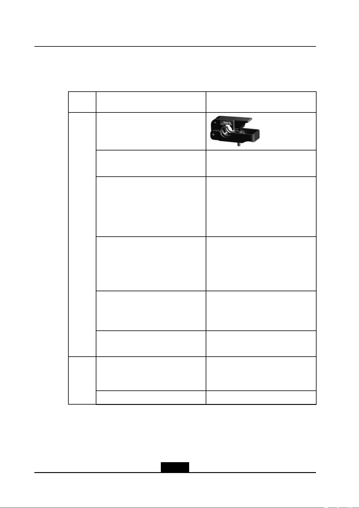
Onefeederconnectorknife
One75Ωcoaxialcablestripper
Onemulti-functionalcrimpingpliers
Special-
purpose
tools
Onemultimeter
NameExample
Onestandingwaveratiotester
Oneearthresistancetester
Oneelectricpercussiondrill
Punch-
ingtools
Severalauxiliarypercussiondrillbits
2-4
SJ-20100722143906-002|02/20/2011(R1.3)ZTEProprietaryandCondential
Page 27
Chapter2InstallationOverview
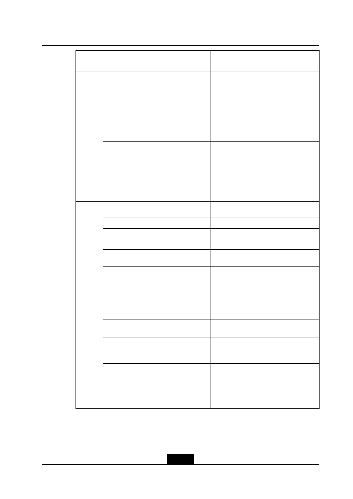
Cate-
gory
Onevacuumcleaner
Powerconnectorboard(providingatleast3
two-phasesocketsand3three-phasesock-
ets,withthecurrentcapacitylargerthan15
A)
Crossscrewdrivers(4”,6”and8”each)
Flatheadscrewdrivers(4”,6”and8”each)
NameExample
Adjustablewrenches(6”,8”,10”and12”
each)
Dual-purposewrenches(17”and19”each)
Onesetofsocketwrenches
General-
purpose
tools
Onepaperknife
5kgnailhammer
One300Wironandone40Wiron
2-5
SJ-20100722143906-002|02/20/2011(R1.3)ZTEProprietaryandCondential
Page 28
ZXSDRR8860InstallationManual
Cate-
gory
Onesetofinner-hexagonwrench
Solderwires
NameExample
One50m(164feet)tapemeasure
One5m(16feet)steeltape
Mea-
sure-
ment
tools
Oneangleinstrument
Onecompass
2-6
SJ-20100722143906-002|02/20/2011(R1.3)ZTEProprietaryandCondential
Page 29
Chapter2InstallationOverview
Cate-
gory
Onelevelbar
Oneplumb
Antistaticwriststrap
slip-proofgloves
Protec-
tiontools
NameExample
Safetyhelmet
Onehacksaw(withseveralsawblades)
Onepairofsharp-nosepliers(8″)
Onepairofdiagonalpliers(8″)
Clamp
tools
Onepairofround-nosepliers(8″)
Onepairofvices(8″)
2-7
SJ-20100722143906-002|02/20/2011(R1.3)ZTEProprietaryandCondential
Page 30
ZXSDRR8860InstallationManual
Cate-
gory
Onesetofneedleles(medium-sized)
Nippers
Onepaintbrush
Onepairofscissors
Onehotairblower
NameExample
Onesolderremovaltool
Onehydrauliccrimper
Onecrowbar
Pulleyset
Auxiliary
tools
Rope
2-8
SJ-20100722143906-002|02/20/2011(R1.3)ZTEProprietaryandCondential
Page 31

Chapter2InstallationOverview
Cate-
gory
Ladder
Spectrumanalyzer(requiredincertainspe-
cialcases)
BTStester
Meters
NameExample
2.3.3On-siteDocuments
Fieldstrengthtester(requiredincertainspe-
cialcases)
ZXSDRR8860installationneedsthefollowingtechnicaldocumentstobeready.
lZXSDRR8860EngineeringExplorationReport
lZXSDRR8860EnvironmentAcceptanceReport
ZXSDRR8860manualkitincludes:
lZXSDRR8860CommissioningandCongurationManual
lZXSDRR8860OperationandMaintenanceManual
lZXSDRR8860TechnicalManual
2-9
SJ-20100722143906-002|02/20/2011(R1.3)ZTEProprietaryandCondential
Page 32

ZXSDRR8860InstallationManual
2.3.4UnpackingAcceptance
2.3.4.1CountingGoods
Context
Therepresentativeofcustomerandtheprojectsupervisormustbepresentonsitewhen
countingreceivedgoods.Ifeitherpartyisnotpresent,transportermustberesponsiblefor
theintactnessofthegoods.
Steps
1.ChecktheDeliveryChecklistofZTECorporation.Checkthetotalnumberofthegoods
andtheintactnessofthepackingboxes.Checkthepackinglisttoseeiftheplaceof
arrivalistheactualinstallationplace.Ifthegoodsareintact,unpackandinspectthem.
Note:
2.3.4.2CrateUnpacking
Itisrecommendedtounpackthegoodsabout30minutesafterreceipt,becausethere
isapossibilityofmoisturecontentduetotemperaturevariations.
2.Theequipmentinspectionlistandunpackingacceptancereportarepresentinthe
rstpackingcarton.Firstly,openrstthepackingcartonandtakeouttheUnpacking
AcceptanceReporttocheckwhetherthegoodsreceivedareinaccordancewiththe
inspectionlist.
3.Duringthecountingandunpackinginspectionprocess,ifanymaterialisfoundshort,
orgoodsdamaged,llintheUnpackingAcceptanceFeedbackTableandcontactZTE
promptly.
–EndofSteps–
Prerequisites
Preparetheappropriatetoolssuchasstraightscrewdriver,pliers,andcrowbar.
Context
Performthefollowingstepstoopenthecrate:
Steps
1.Insertaatheadscrewdriverornailhammerintothemetallatchofthecoverboardof
thecrate,andmovetheatheadscrewdriverornailhammertoloosentheironsheet.
2-10
SJ-20100722143906-002|02/20/2011(R1.3)ZTEProprietaryandCondential
Page 33

Chapter2InstallationOverview
Thenusethecrowbarorpincerstoputthemetallatchinthestraightdirection,as
showninFigure2-2.
Figure2-2PuttingtheMentalLatchinStraightDirection
1.Mentalsheet
2.Coverboard
3.Mentallatch4.Flatheadscrewdriver
ornailhammer
2.Usethetoolstoputallthemetallatchesonthecoverboardofthecrate,andthen
removethecoverboardofthecrate,asshowninFigure2-3.
Figure2-3RemovingCoverBoard
3.Puttheothermetallatchesonthefoursidesofthecrate,removetheboardsandtake
outtheequipmentfromthecrate,asshowninFigure2-4.
2-11
SJ-20100722143906-002|02/20/2011(R1.3)ZTEProprietaryandCondential
Page 34

ZXSDRR8860InstallationManual
Figure2-4RemovingOtherBoards
2.3.4.3CartonUnpacking
–EndofSteps–
Prerequisites
Preparetheappropriatetoolssuchasstraightscrewdriver,diagonalpliers,andpaperknife.
Context
Performthefollowingstepstounpackthecarton:
Steps
1.Usediagonalplierstocutpackingstraps.
2.Useapaperknifetocutadhesivetapealongtheslitsoncartoncover,avoiddamaging
goodsinside.
3.Openthecarton,andremovethefoamboard.
4.Checkthegoodswithinthecarton.
5.Takeouttheantistaticpackingbag.
6.Opentheantistaticpackingbagtotakeouttheelectronicequipmentcomponents,as
showninFigure2-5.
2-12
SJ-20100722143906-002|02/20/2011(R1.3)ZTEProprietaryandCondential
Page 35

Figure2-5TakingOutComponentwithanAntistaticWristStrap
Chapter2InstallationOverview
Note:
lAvoiddamagingtheantistaticbag(Itcanbeusedinthefutureforstorageofspare
parts)duringunpacking.
lWhiletheequipmentismovedtoahotteranddamperplace,waitfor30minutes
beforeunpackingtheequipment.Otherwise,moisturemaycondenseonthe
surfaceoftheequipmentandcausedamage.
lProperlydisposeofrecycledesiccants.
–EndofSteps–
2.3.4.4GoodsAcceptanceandHandover
Context
Performthisprocedureforacceptinggoods,andhandingthemovertooperators.
Steps
1.Acceptance
Basedonthename,categoryandnumbermentionedontheshippinglist,carefully
checkthegoodspiecebypiece.Makesurethatallgoodsmeetthefollowing
conditions:
a.Thereisnobubbly,peeling,nickandlthmarkonthesurfaceofthechassis.
b.Theoilpaintonthechassissurfaceisintact.
c.Allclampingscrewsaretightandintact.
2-13
SJ-20100722143906-002|02/20/2011(R1.3)ZTEProprietaryandCondential
Page 36

ZXSDRR8860InstallationManual
d.Allcomponentsareproperlyinstalledinposition.
e.Theinspectedgoodsareplacedbycategory .
2.Handover
Aftercompletingtheunpackingprocedure,representativeofcustomerandproject
supervisorshouldapproveandsigntheUnpackingforInspectionReport.Bothparties
shouldhaveacopyofUnpackingforInspectionReport.
–EndofSteps–
2-14
SJ-20100722143906-002|02/20/2011(R1.3)ZTEProprietaryandCondential
Page 37

Chapter3
CabinetInstallation
TableofContents
EngineeringIndices....................................................................................................3-1
Pole-mountedInstallationMode.................................................................................3-2
Wall-mountedInstallationMode................................................................................3-11
3.1EngineeringIndices
Table3-1describestheengineeringindicesofZXSDRR8860.
Table3-1ZXSDRR8860EngineeringIndices
OverallDimensionWidthxHeightxDepth:320mmx500mmx172mm
ItemIndices
UpperEnclosureDimensionWidthxHeightxDepth:320mmx370mmx72mm
LowerEnclosureDimensionWidthxHeightxDepth:320mmx500mmx100mm
Weight<22kg
Power-48VDC;-40V~-57V
220VAC:150V~285V/45Hz~65Hz(viaexternal
AC-to-DCconversionlightningbox)
WorkT emperature-40℃to55℃-40℉to131℉
WorkHumidity5%RH~95%RH
PowerConsumptionofNormalWork
Under-48VDCPowerSupply
l1Carrier
àOutputPower:20W/C/S
àPowerConsumption:160W
l2Carrier
àOutputPower:20W/C/S
àPowerConsumption:200W
l3Carrier
àOutputPower:20W/C/S
àPowerConsumption:250W
3-1
SJ-20100722143906-002|02/20/2011(R1.3)ZTEProprietaryandCondential
Page 38

ZXSDRR8860InstallationManual
ThetechnicalindicesoftheindoorDClightningbox,exempliedby
JD40K085C20H2–K1Z,arelistedinTable3-2,whichissubjecttotheactualeld
technicalspecicationsforpracticalapplication.
Table3-2JD40K085C20H2–K1ZDCLightningBoxTechnicalIndices
DimensionsWidthxHeightxDepth:400mmx450mmx100mm(The
NominalWorkingVoltage–48V
InstallationModeIndoorwall-mountinstallation
WorkingT emperature-5℃to70℃
WorkingHumidity≤95%RH
ThetechnicalindicesoftheexternalAC-to-DCconversionlightningbox,exempliedby
GPAD501M54-1A,arelistedinT able3-3,whichissubjecttotheactualeldtechnical
specicationsforpracticalapplication.
ItemIndex
heightoftopcoverboxlockexcluded)
Table3-3GPAD501M54-1AExternalAC-to-DCConversionLightningBoxTechnical
Indices
ItemIndex
DimensionsWidthxHeightxDepth:217mmx288mmx127mm
Weight4.65kg
InputVoltageMin.value:150V
Typicalvalue:220V
Max.value:285V
InputFrequencyMin.value:45Hz
Typicalvalue:50Hz
Max.value:65Hz
InstallationModePole-mountandwall-mountinstallation
WorkingT emperature-40℃+65℃
WorkingHumidity5%95%
3.2Pole-mountedInstallationMode
3.2.1ComponentsUsedinPole-mountInstallation
Themaincomponentsusedinpole-mountinstallationinclude:
lPoleanchorclampcomponents;
lPolexingbracketcomponents.
3-2
SJ-20100722143906-002|02/20/2011(R1.3)ZTEProprietaryandCondential
Page 39

Chapter3CabinetInstallation
Thepoleanchorclampcomponentsareusedforpole-mountinstallationofoneortwo
ZXSDRR8860s.Thepolexingbracketcomponentsareusedforpole-mountinstallation
ofthreeZXSDRR8860s.
Themainpoleanchorclampcomponentsusedinpole-mountinstallationforsingleZXSDR
R8860arelistedinTable3-4
Table3-4MainComponentList1
NameQuantity
Shortanchorclamp2
Longanchorclamp2
Standardspringwasher104
M10×120hexagonheadbolt(fullthread)4
I-typecommonM10hexagonalnut4
Flatwasher104
Standardspringwasher84
M8×40hexagonheadbolt4
Bigwasher84
Themainpoleanchorclampcomponentsusedinpole-mountinstallationfortwoZXSDR
R8860arelistedinT able3-5
Table3-5MainComponentList2
NameQuantity
Longanchorclamp4
Standardspringwasher104
M10×120hexagonheadbolt(fullthread)4
M10×80hexagonheadbolt(fullthread)4
I-typecommonM10hexagonalnut4
Flatwasher104
Standardspringwasher88
M8×40Hexagonheadbolt8
Bigwasher88
Themainpolexingbracketcomponentsusedinpole-mountinstallationforthreeZXSDR
R8860arelistedinTable3-6
3-3
SJ-20100722143906-002|02/20/2011(R1.3)ZTEProprietaryandCondential
Page 40

ZXSDRR8860InstallationManual
Table3-6MainComponentList3
NameQuantity
Polexingbracket4
Standardspringwasher104
M10×120hexagonheadbolt(fullthread)4
I-typecommonM10hexagonalnut4
Flatwasher104
Standardspringwasher812
M8×40hexagonheadbolt12
Bigwasher812
Figure3-1illustratespoleanchorclampcomponents.Figure3-2illustratespolexing
bracketcomponents.
Figure3-1PoleAnchorClampComponents
Figure3-2PoleFixingBracketComponents
3-4
SJ-20100722143906-002|02/20/2011(R1.3)ZTEProprietaryandCondential
Page 41

Chapter3CabinetInstallation
Note:
ThepoleanchorclampcomponentsshowninFigure3-1isadoptedinonepole-mount
installation.Thepoleanchorclampcomponentsusedintwopole-mountinstallationonly
changestwoshortanchorclampsintotwolonganchorclamps,thespeciclistdescribed
inT able3-5
3.2.2InstallingSingleCabinetonPole(Pole–Mount)
Context
ThistopicdescribesthemethodtoxasingleZXSDRR8860cabinetonapole.
Steps
1.Installpoleanchorclampcomponents.
a.Fixanchorclampsontothepole,andaligntheanchorclampholesandscrewthe
boltsabit;
b.Adjustthespacebetweentheclipsbasedonthescrew'spositionofsupporting
panel,andxthesupportingpanelontheclipswithM8boltsandtightenitproperly;
c.ScrewdownM10boltstightly.
Figure3-3illustratestheinstallationofanchorclampcomponents.
Figure3-3Pole-MountInstallation(1)
1.M8×40hexagonhead
bolt
SJ-20100722143906-002|02/20/2011(R1.3)ZTEProprietaryandCondential
2.Standardspring
washer
3-5
3.Bigflatwasher
4.Insulationflange
Page 42

ZXSDRR8860InstallationManual
5.Supportingpanel
6.Insulationboard
7.Longanchorclamp
8.M10×120hexagon
headbolt(fullthread)
9.Pole
10.Flatwasher
11.Standardspring
washer
12.I-typecommonM10
hexagonalnut
13.Shortanchorclamp
2.MounttheZXSDRR8860cabinetonthesupportingpanelandfastenthecabinetwith
fourM6X20hexagonsocketcapscrewsasshowninFigure3-4
Figure3-4Pole-MountInstallation(2)
1.M6Screw2.Retainingboard3.Supportingpanel
–EndofSteps–
3.2.3InstallingTwoZXSDRR8860Pole-mountCabinets
Steps
1.Fixanchorclampsbacktobackontothepole,andaligntheholesandscrewdowna
bitwithbolts.Adjustspacebetweenanchorclampsbasedonthescrews'positionof
supportingpanelasshowninFigure3-5.
3-6
SJ-20100722143906-002|02/20/2011(R1.3)ZTEProprietaryandCondential
Page 43

Figure3-5Pole-mountInstallation(1)
Chapter3CabinetInstallation
1.I-typecommonM10
hexagonalnut
2.Standardspring
washer10
3.Bigflatwasher10
4.Longanchorclamp
5.M10×120hexagon
headbolt(fullthread)
Tip:
DuringtwoZXSDRR8860cabinetinstallation,thesuggestedpolediameteris60to
120mmandtherearetwokindsofboltlengths:
lUsetheboltoflength80mmforpolediameterof60mmto90mm;
lUsetheboltoflength120mmforpolediameterof90mmto120mm.
2.FixtwosupportingpanelsontheanchorclampwithM8boltsandscrewM10bolts
tightly,asshowninFigure3-6.
3-7
SJ-20100722143906-002|02/20/2011(R1.3)ZTEProprietaryandCondential
Page 44

ZXSDRR8860InstallationManual
Figure3-6Pole-mountInstallation(2)
1.M8×40Hexagonhead
bolt
2.Standardspring
washer8
3.Bigflatwasher8
4.Insulationflange
5.Supportingpanel
6.Insulationboard
7.Longanchorclamp
3.MountthetwoZXSDRR8860cabinetsonthesupportingpanelandfastenthecabinet
withfourM6×20hexagonsocketcapscrewsasshowninFigure3-7.
Figure3-7Pole-mountInstallation(3)
–EndofSteps–
3-8
SJ-20100722143906-002|02/20/2011(R1.3)ZTEProprietaryandCondential
Page 45

3.2.4InstallingThreeZXSDRR8860CabinetsonPole
Steps
1.Fixthetwosetsofxingbracketsontothepoleandaligntheholesandscrewitabit
withbolts,asshowninFigure3-8.
Figure3-8Pole-mountInstallation(1)
Chapter3CabinetInstallation
1.FixingBracket
2.M10×120hexagon
headbolt(fullthread)
3.Standardspring
washer10
4.Flatwasher10
5.I-typecommonM10
2.Adjustspacebetweenthexingbracketsbasedonthescrews'positionofinsulation
boardsatthebackofsupportingpanelsasshowninFigure3-9.Fixthreesupporting
panelsonthexingbracketswithM8bolts.ScrewthexingbracketswithM10bolts.
hexagonalnut
3-9
SJ-20100722143906-002|02/20/2011(R1.3)ZTEProprietaryandCondential
Page 46

ZXSDRR8860InstallationManual
Figure3-9Pole-mountInstallation(2)
1.Fixingbracket
2.Insulationboard
3.Supportingpanel
4.Insulationflange
5.Bigflatwasher8
6.Standardspring
washer8
7.M8×40Hexagonhead
bolt
3.MounttheZXSDRR8860cabinetsonthesupportingpanelsandfastenthecabinets
withM6×20hexagonsocketcapscrewsasshowninFigure3-10.
Figure3-10Pole-mountInstallation(3)
3-10
SJ-20100722143906-002|02/20/2011(R1.3)ZTEProprietaryandCondential
Page 47

Tip:
Thesidewithoutxingbracketcanbelocatedalongthewall.
–EndofSteps–
3.3Wall-mountedInstallationMode
3.3.1ComponentsUsedinWall-MountInstallation
Thecomponentsusedinwall-mountinstallationarelistedinT able3-7
Table3-7MainComponents
NameQuantity
Supportingpanel1
Chapter3CabinetInstallation
Drilltemplate1
M8×80expansionbolt4
Bigwasher84
ThesupportingpanelisshowninFigure3-11.Theholemarkingdesigntemplateisshown
inFigure3-12.
Figure3-11SupportingPanel
3-11
SJ-20100722143906-002|02/20/2011(R1.3)ZTEProprietaryandCondential
Page 48

ZXSDRR8860InstallationManual
Note:
Thesupportingpanel,asthecommoncomponentinZXSDRR8860installation,isused
inthewall-mount,pole-mountandgantry-mountinstallationmodes.
Figure3-12HoleMarkingDesignT emplate(Unit:mm)
3.3.2InstallingCabinetonWall(Wall-Mount)
Context
Figure3-13illustratesthespacerequirement(Unit:mm)forwall-mountinstallation.
3-12
SJ-20100722143906-002|02/20/2011(R1.3)ZTEProprietaryandCondential
Page 49

Chapter3CabinetInstallation
Figure3-13SpaceRequirementforWall-mountInstallation(Unit:mm)
Steps
1.Firstlymarktheholepositionsonthewallwithholedesigntemplate.Drillthemarked
pointsabout60mmwithpercussivedrillandinstalltheexpansionbolts.
2.FixthesupportingpanelonthewallwithboltsasshowninFigure3-14
Figure3-14SupportingPanelInstallationonWall
1.M8×80expansionbolt
2.Insulationboard
3.Supportingpanel
SJ-20100722143906-002|02/20/2011(R1.3)ZTEProprietaryandCondential
4.Insulationflange
5.Bigflatwasher8
6.Standardspringmat8
3-13
7.M8nut
Page 50

ZXSDRR8860InstallationManual
l
3.MounttheZXSDRR8860cabinetontothesupportingpanel,andfastenthecabinet
withfourM6X20hexagonsocketcapscrewsasshowninFigure3-15.
Figure3-15MountingCabinet
1.Supportingpanel2.M6safeguardscrew3.Retainingboard
–EndofSteps–
3-14
SJ-20100722143906-002|02/20/2011(R1.3)ZTEProprietaryandCondential
Page 51

Chapter4
ExternalCableInstallation
TableofContents
ExternalCableLayout................................................................................................4-1
ExternalCableInstallationFlow.................................................................................4-2
Specicationsof1+3+3WaterproofProcessingwithPlasterandT ape.......................4-4
InstallingPowerCable................................................................................................4-6
InstallingGroundingCable.........................................................................................4-7
InstallingFiberbetweenBBUandRRU......................................................................4-9
InstallingFiberbetweenRRUandRRU....................................................................4-10
InstallingEnvironmentMonitoringCable...................................................................4-12
InstallingAISGControlCable...................................................................................4-13
InstallingFrequencyPointExtensionCable..............................................................4-14
InstallingJumper......................................................................................................4-15
InstallingPIMDC......................................................................................................4-16
4.1ExternalCableLayout
TheconnectionrelationshipofZXSDRR8860externalcablesisdescribedinTable4-1.
Table4-1ZXSDRR8860ExternalCableConnectionRelationship
NameConnectionRelationshipDescription
PowercableConnectstheZXSDR
GroundingcableConnectsoneZXSDR
R8860powerinterface(DCIN)
tothepowersupplyequipment
interface
R8860groundbolttothe
copperbar
Oneendistheaviationplugand
theotherendisreservedfor
powercablemadeonsite.The
lengthofcableisbasedonthe
engineeringsurvey.
Thegroundingcableismade
upofstrandsofame-retardant
wire.Thecrosssectionalarea
ofZXSDRR8860grounding
cableis10mm
groundingcableisyellowand
green.Copperlugsarecrimped
atbothendsoftheZXSDR
R8860groundingcable.
2
.Thecolorof
4-1
SJ-20100722143906-002|02/20/2011(R1.3)ZTEProprietaryandCondential
Page 52

ZXSDRR8860InstallationManual
NameConnectionRelationshipDescription
OpticalFiberTherearetwotypesofZXSDR
R8860ber:BBUconnection
/ZXSDRR8860cascading.
EnvironmentmonitoringcableConnectstheZXSDR
R8860environmentmonitoring
interfaceMONtotheexternal
monitoringcomponentsorthe
drycontact.
AISGcontrolcableConnectstheZXSDR
R8860debugginginterface
(AISG)tothecontrolinterfaceof
electrical-adjustmentantenna.
Frequencypointextension
cable
InterconnectstheZXSDRR8860
RXin/RXoutinterfaces.
TherearetwotypesofZXSDR
R8860opticalber:oneusedin
BBUconnectionandtheother
usedincascadingbetween
ZXSDRR8860s.
Aendoftheenvironment
monitoringcableisPINdesign.
Bend,with3mlengthintotal,
needsmakingbasedonthe
on-siteengineering.
AISGisusedforcontrolofthe
electrical-adjustmentantenna.
Thefrequencypointextension
cableusuallyadoptsthenished
1/2″jumperwith2mlength.The
jumpercanbeself-madebased
onthereal-timeconditionon
site.
AandBendsofjumperareN
connectors(male).
Antenna,feederandjumperConnectstheZXSDRR8860to
themainfeeder.
4.2ExternalCableInstallationFlow
Figure4-1liststheinstallationowofexternalcable.Thisowcanbeadjustedbasedon
thereal-timecondition.
TheRFjumperusuallyadopts
thenished1/2″jumperwith
2mlength.Thejumpercan
beself-madebasedonthe
real-timeconditiononsite.
TheendofjumperisN
connector(male)andtheother
endisDINconnector(female).
4-2
SJ-20100722143906-002|02/20/2011(R1.3)ZTEProprietaryandCondential
Page 53

Figure4-1ExternalCableInstallationFlow
Chapter4ExternalCableInstallation
4-3
SJ-20100722143906-002|02/20/2011(R1.3)ZTEProprietaryandCondential
Page 54

ZXSDRR8860InstallationManual
4.3Specificationsof1+3+3WaterproofProcessing
withPlasterandTape
Overview
Waterproofprocessingmustbeperformedonalltheoutdoormetalconnectorsofthe
RRUs.Theconnectorsinclude:thegroundingcableconnector,feederconnector,optical
berconnector,powercableconnector,anddrycontactconnectingcableconnector.
In1+3+3plasterandtapewaterproofprocessing,thewaterproongself-adhesive
insulatedtape(plasterforshort)+electricalinsulatedtape(tapeforshort)+UV-stabilized
cablefastenersontwoendsareadopted.Thisis1+3+3waterproofprocessing,namely,
1layeroftape+3layersofplaster+3layersoftape.Figure4-2showstheplasterand
tape.
Figure4-2AppearanceofthePlasterandTape
OperationProcedure
1.Cleantheconnectorsandthepartofthecablesurfacesthatistobesealed.
2.Tosimplifyremovalofthe1+3+3waterproofmaterialasawholeinfuturemaintenance,
wrapalayeroftapewiththestrengthofunwrappingthetapefrombottomtotop,
overlappingeachturn50percent,asshowninFigure4-3.
Figure4-3WrappingaLayerofTape
3.Unwraptheplaster,andpeelthepaperbacking.Then,extendtheplastertooneto
twotimestheoriginalsize,facethestickyside(fromwhichsidethepaperbackingis
removed)totheconnectororcable,andthenapplythreelayersofplaster,frombottom
totop,fromtoptobottom,andfrombottomtotop.Overlapeachturn50percent.Use
yourngerstomoldtheplastersothattheplasterbetweenthreelayersiswellbond,
asshowninFigure4-4.
4-4
SJ-20100722143906-002|02/20/2011(R1.3)ZTEProprietaryandCondential
Page 55

Chapter4ExternalCableInstallation
Figure4-4WrappingThreeLayerofPlaster
4.Withthestrengthofunwrappingthetape,wrapthreelayersoftape,frombottomto
top,fromtoptobottom,andfrombottomtotop,overlappingeachturn50percent.Use
yourngerstomoldthetapesothattheplasterandtapearewellbond,asshownin
Figure4-5.
Figure4-5WrappingaLayerofTape
5.Onthetwoend,tightlybindUV-stabilizedcablefastenerstothetape(underwhich
thereareplasterlayers)topreventremovalofthetape,asshowninFigure4-6.
4-5
SJ-20100722143906-002|02/20/2011(R1.3)ZTEProprietaryandCondential
Page 56

ZXSDRR8860InstallationManual
Figure4-6BindingCableFasteners
Note
1.Wrapthetapewiththestrengthofunwrappingthetape(thatis,thestrengthofnaturally
unwrappingthetape).Thetapeshouldnotbeextended.
2.Extendtheplastertoonetotwotimestheoriginalsizewhilewrapping.
3.Overlapeachturnofthetapeandplasteratleast50percent.
4.Thedirectionsoftheplasterandtapeshouldbethesame.Thedirectionmustbegood
forfasteningthescrew.Thispreventsshrinkoftheextendedplasterfromloosening
theconnector.
5.Onthetwoends,overlaptheplasterandtapeforoneturn(whenchangingthe
wrappingdirection).
6.Afterwrapping,useyourngerstomoldtheplastersothattheplasterbetweenthe
layersiswellbond.
7.Thewrappinglengthofthetapemustbe(about10mm)longerthanthatofplaster,
especiallyonthecableend.Ensurethattheplasterisoverthetapesothatthe1+3+3
waterproofmaterialcanberemovedasawholeinfuturemaintenancewithcables
undamaged.
8.Afterwrapping,cuttheplasterandtapewiththescissorsorknife.Donotbreakthe
plasterortapedirectlywithyourhands.
9.Bindthecablefastenerstothetape(underwhichthereareplasterlayers)toprevent
removalofthetapeorshrinkoftheplasterifthecablefastenersareloosened.
4.4InstallingPowerCable
Context
TheZXSDRR8860cabinetadopts-48VDC/220VACpowersupply.EndAistheaviation
plugandEndBisreservedforself-madepowercableonsite.Thelengthofpowercable
isaccordingtotheengineeringsurvey.
ZXSDRR8860Figure4-7showsthestructureofpowercable.
Figure4-7PowerCablestructure
4-6
SJ-20100722143906-002|02/20/2011(R1.3)ZTEProprietaryandCondential
Page 57

Chapter4ExternalCableInstallation
TheACandDCpowercablesarethesameinappearancebutdifferentincorecolorand
quantity,asdescribedinT able4-2andT able4-3.
Table4-2ColorandSpecicationofDCPowerCable
ColorSpecication
Blue-48V
Black-48VGND
Table4-3ColorandSpecicationofACPowerCable
ColorSpecication
BlueN
BlackorKellyPE
BrownL
Steps
1.ConnectEndAofpowercablewithDC/ACINinterfacelocatedatthebottomof
ZXSDRR8860.
2.StriptheprotectivecoatofEndBandconnectitwiththeDC/ACinputpowersource
accordingtocolorsoftheinsidecorecable.
3.MakewaterproofprotectionofEndB.
4.Attachlabelsatbothendsofthepowercable.
5.Fixthepowercable.
6.Performingoutdoorconnectorwaterproofprocessing,referto4.3Specicationsof
1+3+3WaterproofProcessingwithPlasterandTape.
–EndofSteps–
4.5InstallingGroundingCable
Context
Thegroundingcableismadeupofstrandsofame-retardantwire.Thecrosssectional
areaofZXSDRR8860groundingcableis10mm
andgreen.CopperlugsarecrimpedatbothendsoftheZXSDRR8860groundingcable,
asshowninFigure4-8.
2
.Thecolorofgroundingcableisyellow
4-7
SJ-20100722143906-002|02/20/2011(R1.3)ZTEProprietaryandCondential
Page 58

ZXSDRR8860InstallationManual
Figure4-8GroundingCableStructure
Steps
1.CoverandxacopperlugontheagroundingboltoftheZXSDRR8860cabinet,as
showninFigure4-9.
Figure4-9ZXSDRR8860GroundingBolt
1.Groundingbolt
2.Connecttheothercopperlugtotheearth-networkingcopperbarandxitwithabolt,
asshowninFigure4-10.
4-8
SJ-20100722143906-002|02/20/2011(R1.3)ZTEProprietaryandCondential
Page 59

Chapter4ExternalCableInstallation
Figure4-10Earth-networkCopperBar(Unit:mm)
3.Attachthelabelonthegroundingcable.
4.Measurethegroundingresistanceandmakesureitlessthan5Ω.
5.Performingoutdoorconnectorwaterproofprocessing,referto4.3Specicationsof
1+3+3WaterproofProcessingwithPlasterandTape.
–EndofSteps–
4.6InstallingFiberbetweenBBUandRRU
Prerequisites
TheZXSDRR8860cabinetmustbeinstalledandxedsuccessfully.
Context
Figure4-11showsberconnectionbetweenZXSDRR8860andBBU.
Figure4-11FiberConnectionbetweenZXSDRR8860andBBU
1.OutdoorSealComponent
WhileconnectingaBBUtoZXSDRR8860,makesurethatthebasebandRFberinterface
(LC1/2)oftheZXSDRR8860isconnectedtotheopticalinterfaceconnectoroftheBBU.
Steps
1.Attachlabelsatbothendsoftheber.
4-9
SJ-20100722143906-002|02/20/2011(R1.3)ZTEProprietaryandCondential
Page 60

ZXSDRR8860InstallationManual
2.AdjustthesideofEndAwiththecolormarkandinserttheZXSDRR8860ber
interface,andscrewdownthenuts,asshowninFigure4-12
Figure4-12OpticalFiberInstallation
1.Colormark
3.ConnectEndAofthebertothebasebandRFberinterface(LC1/2)oftheZXSDR
R8860.
4.ConnectEndBoftheber,whichisaDLCconnector,totheBBUopticalconnector.
5.ScrewdowntheoutdoorsealcomponentatEndAforwaterproong.
6.Performingoutdoorconnectorwaterproofprocessing,referto4.3Specicationsof
1+3+3WaterproofProcessingwithPlasterandTape.
–EndofSteps–
4.7InstallingFiberbetweenRRUandRRU
Prerequisites
ThecascadingZXSDRR8860cabinetsmustbeinstalledandxedsuccessfully.
Context
Figure4-13showsberconnectionbetweenZXSDRR8860s.
4-10
SJ-20100722143906-002|02/20/2011(R1.3)ZTEProprietaryandCondential
Page 61

Chapter4ExternalCableInstallation
Figure4-13FiberConnectionbetweenZXSDRR8860s
1.OutdoorSealComponent
WhileinterconnectingtheZXSDRR8860s,makesurethatthetwobasebandRFber
interfaces(LC1/2)oftheZXSDRR8860areconnected.
Steps
1.Attachlabelsatbothendsoftheopticalber.
2.AdjustthesideofEndAwiththecolormarkandinserttheZXSDRR8860ber
interface,andscrewdownthenuts,asshowninFigure4-14.
Figure4-14OpticalFiberInstallation
1.Colormark
3.ConnectEndAoftheopticalbertothebasebandRFberinterface(LC1/2)ofthe
ZXSDRR8860.
4.ConnectEndBoftheopticalbertotheotherbasebandRFberinterface(LC1/2)of
theZXSDRR8860.
5.ScrewdowntheoutdoorsealcomponentatEndAforwaterproong.
4-11
SJ-20100722143906-002|02/20/2011(R1.3)ZTEProprietaryandCondential
Page 62

ZXSDRR8860InstallationManual
6.Performingoutdoorconnectorwaterproofprocessing,referto4.3Specicationsof
1+3+3WaterproofProcessingwithPlasterandTape.
–EndofSteps–
4.8InstallingEnvironmentMonitoringCable
Prerequisites
TheZXSDRR8860cabinetmustbeinstalledandxedsuccessfully.
Context
Theenvironmentmonitoringcableprovidesa485interface,usedforZXSDRR8860
environmentmonitoring.Inaddition,thecablealsoprovidesfourextensionaccessesfor
externaldrycontactmonitoring.
EndAisthe37PINconnector,andEndBismadebyon-siteengineering.Thetotallength
is3m.Figure4-15showstheappearanceofenvironmentmonitoringcable.
Figure4-15EnvironmentMonitoringCable
Theconnector,connectingtheenvironmentmonitoringcabletotheZXSDRR8860,
adopts37–coreaviationjack.TheconnectoraccordswiththeGJB599specication.The
connectorappearanceisasshowninFigure4-16
Figure4-16AviationJackAppearance
Table4-4describestheconnectorpins.
Table4-4CablePinDescription
PinCore-CableColorSignalDescription
15/16Whiteandblue/blueDrycontact4-/+
4-12
SJ-20100722143906-002|02/20/2011(R1.3)ZTEProprietaryandCondential
Page 63

Chapter4ExternalCableInstallation
PinCore-CableColorSignalDescription
17/18Whiteandorange/orangeDrycontact3-/+
19/20Whiteandgreen/greenDrycontact2-/+
21/22Whiteandbrown/brownDrycontact1-/+
23/24Redandblue/blueRS485receive
25/26Redandorange/orangeRS485transmit
Steps
1.ConnectEndAtotheMONinterfacelocatedatthebottomofZXSDRR8860.
2.ConnectEndBwithexternalmonitoringdevicesordrycontacts.
3.AttachthelabelatEndB.
4.Performingoutdoorconnectorwaterproofprocessing,referto4.3Specicationsof
1+3+3WaterproofProcessingwithPlasterandTape.
–EndofSteps–
4.9InstallingAISGControlCable
Context
TheAISGcontrolcableisusedforcontroloftheelectricaladjustmentantenna.
Figure4-17showsthestructureoftheAISGcontrolcable.
Figure4-17AISGControlCableStructure
Table4-5describestheserialNo.meaningofAISGcontrolcable.
Table4-5AISGControlCableDescription
SerialNo.NameMeaning
1TRX_ANT_485_+RS485+
4-13
SJ-20100722143906-002|02/20/2011(R1.3)ZTEProprietaryandCondential
Page 64

ZXSDRR8860InstallationManual
SerialNo.NameMeaning
2TRX_ANT_485_-RS485-
3,4TRX_ANT_28V28V
5,6TRX_ANT_28VGND28VGND
7,8NCNull
Steps
1.ConnectEndAtotheZXSDRR8860debugginginterface(AISG)andscrewdownthe
bolt;
2.ConnectEndBtothecontrolinterfaceofelectricaladjustmentantennaandscrew
downthebolt.
3.Performingoutdoorconnectorwaterproofprocessing,referto4.3Specicationsof
1+3+3WaterproofProcessingwithPlasterandTape.
–EndofSteps–
4.10InstallingFrequencyPointExtensionCable
Prerequisites
ThetwoZXSDRR8860cabinetstobecombinedmustbeinstalledandxedsuccessfully.
Context
Afterthecombinationofcabinets,theZXSDRR8860cansupport8carriersectorsatmost.
ThetwoZXSDRR8860cabinetsareconnectedthroughtheirconnectinginterfacessuchas
RXinandRXoutbytwofrequencypointextensioncables.Figure4-18showsthestructure
ofthefrequencypointcable.EndAandEndBareNconnectors(male).
The2M1/2″jumperisoftenusedforthefrequencypointextensioncable.Itmaybe
preparedonsiteifnecessary.
Figure4-18FrequencyPointExtensionCable
Steps
1.ConnectEndAofthefrequencypointextensioncabletothefrequencypointextension
interfaceRXINofoneZXSDRR8860;
4-14
SJ-20100722143906-002|02/20/2011(R1.3)ZTEProprietaryandCondential
Page 65

4.11InstallingJumper
Chapter4ExternalCableInstallation
2.ConnectEndBtoRXoutoftheotherZXSDRR8860;
3.ConnecttheremainingRXin/RXoutinterfacesofthetwocombinedcabinetswiththe
otherfrequencypointextensioncable.
4.Performingoutdoorconnectorwaterproofprocessing,referto4.3Specicationsof
1+3+3WaterproofProcessingwithPlasterandTape.
–EndofSteps–
Context
OneendofRFjumperconnectswiththemainfeederandtheotherendconnectswiththe
antennafeederinterfaceofZXSDRR8860cabinet.BeforeinstallingtheRFjumper,the
mainfeederisinstalled.
TheRFjumperadoptsthe1/2″jumperwitha2mlength.Thejumpercanalsobeself-made
accordingtotheon-sitecondition.
TheinstallationpositionofRFjumperisasshowninFigure4-19.
Figure4-19RFJumperInstallation
PerformthefollowingstepstoinstalltheRFjumper.
Steps
1.ConnecttheDINconnector(male)ofRFjumperwiththeDINconnector(female)of
mainfeeder.
2.ConnecttheDINconnector(male)ofRFjumperwiththeDINconnector(female)of
ZXSDRR8860cabinet.
3.SealtheconnectorswithwaterproofadhesivetapesandPVCtapes.
4-15
SJ-20100722143906-002|02/20/2011(R1.3)ZTEProprietaryandCondential
Page 66

ZXSDRR8860InstallationManual
4.Performingoutdoorconnectorwaterproofprocessing,referto4.3Specicationsof
1+3+3WaterproofProcessingwithPlasterandTape.
–EndofSteps–
4.12InstallingPIMDC
4.12.1PIMDCechnicalIndices
TheoutdoorDClightningbox(PIMDC)isusedforsurgeprotectionofZXSDRR8860.The
followingdescribesitscharacters:
lBreaksawayfromthepowersupplysystempermanentlytoavoidshortcircuitin
electricnetworkwhenmalfunctionedorfailed.
lAdoptsspecialvoltage-sensitivemoduleswithovercurrentandoverheatprotection,
highsurgecurrentandlowresidualvoltage.
lEquipsremotesignallingalarminterface.(Theremotedrycontactisnormallyclosed
atnormalcondition.Whensomepartsfailedorpoweriscutedoff,theremote
signallingdrycontactturnstobenormallyopenfromnormallyclosed.)
lTheenclosureismadeofaluminumdie-castingmetalanditsprotectiondegree
reachesthedemandofIP55.Itcanbeinstalledoutdoorforlongtermuseandhas
goodameretardance.
EngineeringTechnicalIndices
Table4-6describestheengineeringtechnicalindicesofPIMDC.
Table4-6EngineeringT echnicalIndicesofPIMDC
NominalOperatingV olt-
ageUnDC-48VConnectionTypeInSeries
Max.ContinuousOperat-
ingVoltageUcDC-75VProtectionModel
NominalDischargeCur-
rentIn8/20μs20kAResponseTime≤25ns
LeadAreaClampedby
Max.DischargeCurrent
Imax8/20μs40kA
ProtectionLevelUpIn≤180V
RatedLoadCurrentIL18AOperatingT emperature-40℃+70℃
LoadSideImpactCapacity
8/20μs8kAOperatingHumidity109525oC
thePowerConnecting
Terminal2.5mm
LeadAreaClampedby
DryContactTerminal0.15mm
Differentialand
CommonMode
2
2
10mm
2
2
1.3mm
Die-castingAlu-
Enclosure
SJ-20100722143906-002|02/20/2011(R1.3)ZTEProprietaryandCondential
minumSprayPaintAltitude≤3000m
4-16
Page 67

4.12.2PIMDCAppearance
Chapter4ExternalCableInstallation
DegreeofProtectionIP55Weight1.2kg
PIMDCAppearanceisshowninFigure4-20.
Figure4-20PIMDCAppearance
4-17
SJ-20100722143906-002|02/20/2011(R1.3)ZTEProprietaryandCondential
Page 68

ZXSDRR8860InstallationManual
4.12.3PIMDCInstallationDescription
Inatallation
FastenthePIMDCononesideoftheZXSDRR8860mountingbracketusingtwoscrews,
asshowninFigure4-21.
Figure4-21InstallingPIMDC
ConnectingCables
OpenPIMDCcabinet,ConnectthePIMDCcables,asshowninFigure4-22.
4-18
SJ-20100722143906-002|02/20/2011(R1.3)ZTEProprietaryandCondential
Page 69

Figure4-22PIMDCConnection
Chapter4ExternalCableInstallation
1.Groundcablebetweenthe
PIMDCandtheRRU
2.Inputpowercableofthe
PIMDC
3.Inputpowercableofthe
RRU
4.Drycontactcable
5.GroundcableofthePIMDC
1.ConnectgroundcableofthePIMDC,thegroundcableofthePIMDCisshowninFigure
4-22"5".
2.ConnecttheA-endtothe"InputSide"ofthePIMDCthroughthewaterproofplastic
ring:connectthebluecableto-48Vportandconnecttheblackcableto-48VRTNport
(theinputpowercableofthePIMDCisshowninFigure4-22"2".)
3.Fastenthepowercablewithalatch.Note:Thislatchshouldstaycontactwiththe
shieldedlayerofthepowercable,asshowninFigure4-23.
4-19
SJ-20100722143906-002|02/20/2011(R1.3)ZTEProprietaryandCondential
Page 70

ZXSDRR8860InstallationManual
Figure4-23ConnectPowerInputCable
4.ConnecttheA-endoftheoutputpowercable(asshowninFigure4-22"3".)tothe
devicesideonthePIMDC:connectthebluecableto-48Vportandconnecttheblack
cableto-48VRTNport,asshowninFigure4-24.
5.Connectthewhiteandbluedrycontactcables(asshowninFigure4-22"4".)tothe
"Alarm"ports,asshowninFigure4-24.
Figure4-24ConnectingOutputPowerCableandDryContactCables
4-20
SJ-20100722143906-002|02/20/2011(R1.3)ZTEProprietaryandCondential
Page 71

Chapter4ExternalCableInstallation
6.ConnectgroundcablebetweenthePIMDCandtheRRU(asshowninFigure4-22"1")
toRRU.
7.Performingoutdoorconnectorwaterproofprocessing,referto4.3Specicationsof
1+3+3WaterproofProcessingwithPlasterandT ape.
4-21
SJ-20100722143906-002|02/20/2011(R1.3)ZTEProprietaryandCondential
Page 72

ZXSDRR8860InstallationManual
Thispageintentionallyleftblank.
4-22
SJ-20100722143906-002|02/20/2011(R1.3)ZTEProprietaryandCondential
Page 73

Chapter5
MainAntennaFeederSystem
Installation
TableofContents
MainAntennaFeederSystemStructure.....................................................................5-1
MainAntennaFeederSystemInstallationPreparation...............................................5-7
MainAntennaFeederSystemInstallationFlow..........................................................5-8
AntennaInstallation....................................................................................................5-9
FeederInstallation....................................................................................................5-15
InstallingFeederHermetic-window...........................................................................5-25
FeederIndoorIngoing..............................................................................................5-27
PerformingAntennaFeederSystemTest.................................................................5-31
PerformingOutdoor-ConnectorWaterproofProcessing............................................5-32
PerformingFeederHermetic-windowWaterproofProcessing...................................5-36
ChassisJumperInstallationDescription...................................................................5-39
VSWRTest...............................................................................................................5-40
5.1MainAntennaFeederSystemStructure
ThetypicalcongurationsofZXSDRR8860mainantennafeedersystemdescribedbelow
includes:
lZXSDRR8860conguredwithcommonantenna
lZXSDRR8860conguredwithcommonantennaandAISGdualtoweramplier
lZXSDRR8860conguredwithelectricallytunedantenna(1)
lZXSDRR8860conguredwithelectricallytunedantenna(2)
lZXSDRR8860conguredwithelectricallytunedantenna,AISGdualtoweramplier
ZXSDRR8860conguredwithcommonantenna
Inthisconguration,generallyZXSDRR8860installationpositionisnearantennaand
theyareallinstalledonthebuildingtop.ZXSDRR8860isconnectedtotheantennaby
1/2″feederdirectly,occasionally5/4″or7/8″feederisadopted,asshowninFigure5-1.
5-1
SJ-20100722143906-002|02/20/2011(R1.3)ZTEProprietaryandCondential
Page 74

ZXSDRR8860InstallationManual
Figure5-1ZXSDRR8860ConguredwithCommonAntenna
ZXSDRR8860conguredwithcommonantennaandAISGdualtoweramplier
Inthisconguration,generallyZXSDRR8860isinstalledonthetower.ZXSDRR8860is
connectedtotheantennaby5/4″or7/8″feeder,asshowninFigure5-2.
5-2
SJ-20100722143906-002|02/20/2011(R1.3)ZTEProprietaryandCondential
Page 75

Chapter5MainAntennaFeederSystemInstallation
Figure5-2ZXSDRR8860ConguredwithCommonAntenna,AISGDualTowerAmplier
ZXSDRR8860conguredwithelectricallytunedantenna(1)
Inthisconguration,generallyZXSDRR8860installedneartheantennaonthebuilding
top.ZXSDRR8860isconnectedtotheantennaby1/2″feederdirectly,occasionally5/4″or
7/8″feederisadopted,asshowninFigure5-3.
5-3
SJ-20100722143906-002|02/20/2011(R1.3)ZTEProprietaryandCondential
Page 76

ZXSDRR8860InstallationManual
Figure5-3ZXSDRR8860ConguredwithElectricallyTunedAntenna(1)
ZXSDRR8860conguredwithelectricallytunedantenna(2)
Inthisconguration,generallyZXSDRR8860isinstallednearthetopofthetower.ZXSDR
R8860isconnectedtotheantennaby5/4″or7/8″feederisadopted,asshowninFigure
5-4.
5-4
SJ-20100722143906-002|02/20/2011(R1.3)ZTEProprietaryandCondential
Page 77

Chapter5MainAntennaFeederSystemInstallation
Figure5-4ZXSDRR8860ConguredwithElectricallyTunedAntenna(2)
ZXSDRR8860conguredwithelectricallytunedantenna,AISGdualtoweramplier
Inthisconguration,generallyZXSDRR8860isinstallednearthetopofthetower.ZXSDR
R8860isconnectedtotheantennaby5/4″or7/8″feederisadopted,asshowninFigure
5-5.
5-5
SJ-20100722143906-002|02/20/2011(R1.3)ZTEProprietaryandCondential
Page 78

ZXSDRR8860InstallationManual
Figure5-5ZXSDRR8860ConguredwithElectricallyTunedAntennaandAISGDual
TowerAmplier
5-6
SJ-20100722143906-002|02/20/2011(R1.3)ZTEProprietaryandCondential
Page 79

5.2MainAntennaFeederSystemInstallation Preparation
ProperantennainstallationisveryimportanttoZXSDRR8860systemreliableoperation.
Beforeinstallation,makesurethatinstallationstaffisqualiedandthefollowing
requirementsaresatised.
PersonnelRequirement
Normally,supervisorsareinchargeofdirectionandsupervision,whereasinstallation
personnelcarryouttheinstallation.
lInstallationSupervisor
Therequirementsfortheinstallationsupervisorareasfollows:
àFamiliarwithallmaterials,toolsandoperationmethods.
àInchargeofassigningdifferentworktotheproperemployeewhoisgoodatthe
operation,especiallywhileworkingontheirontower.
Chapter5MainAntennaFeederSystemInstallation
Note:
Safetyisthemostimportantconsiderationwhenassigningwork.
lInstallationPersonnel
Therequirementsfortheinstallationpersonnelareasfollows:
àInstallationemployeesarerequiredtoinstallantennasystemskillfullyunderthe
directionofsupervisor.
àEmployeesontowermustbequaliedandingoodphysicalstate.
àInstallationafterdrinkingisforbidden.
EnvironmentRequirement
Payattentiontofollowingitemsandcheckwhethertheseitemsaccordwithrequirements
inengineeringdesign.
lLightningprotectionandgrounding
ZXSDRR8860isusuallylocatedoutdoors.Thegroundingstakeandoutdoor
lightning-protectinggroundingcablesareinstalledbytheoperator,andthesupervisor
shouldconrmlightning-protectinggroundingcablesareinstalledproperly.
lPoleandsupportingrack
Accomplishinstallationofantennasupportingrackandpoleaccordingtoproject
designrequirement.Thestabilityofthesupportingrackandpoleshouldbein
accordancewiththedesignrequirement.
5-7
SJ-20100722143906-002|02/20/2011(R1.3)ZTEProprietaryandCondential
Page 80

ZXSDRR8860InstallationManual
lFeederlayout
Fieldengineerneedtoconsultwithoperatorengineers,anddeterminetherouteof
feeder.
lElectronicpowerenvironment
lZXSDRR8860antennaandfeedersystemcannotbeinstalledtooneartopublic
electricpowercables.
SafetyPrecautions
Ensurethefollowingprecautionsbeforeantennainstallation:
lTakenecessarymeasuresforpersonalandequipmentsafety.
lPersonnelundertowermustwearsafetyhelmets.
lPersonnelontowermustwearsafetybelt.
lNeverclimbtowerwithlooseclothesandwet/slipperyshoes.
lDuringactiveantennaadjustment,wearradiation-shieldingclothingandturnoffpower
ampliertoavoidradiationeffects.
lIfpossible,installinsunnyandwindlessdays.Installationisforbiddeninrain,strong
wind,thunderandlightning.
lMakecautionbrandinengineeringeldandkeeppasserbyawayfromengineering
eld,especiallykids.
lWhenworkingontower,putunusedtoolsinatoolbagandpreventthemfromdropping
downfromtowertohurtpeople.
ToolsRequirement
Thefollowingtoolsarerequiredformainantennafeedersysteminstallation:
lMeasuretools
Compass,multimeter,anglemeter,andtapemeasure
lSpecialtools
Specialtoolsandinstrumentsformainfeederconnectormakingandtest
lRegulartools
Adjustablewrench,sharp-nosepliers,diagonalpliers,hacksaw(withseveralsaw
blades)
lProtectiontools
Safetyhelmet,safetybelt,safetyrope,gloves,radiation-shieldingclothes,multiple
powersocketandsealedcanvastoolbag
lOthertools
Toolsforlifting,e.g.Ladder
5.3MainAntennaFeederSystemInstallationFlow
Figure5-6showstheinstallationowofmainantennafeedersystem.
5-8
SJ-20100722143906-002|02/20/2011(R1.3)ZTEProprietaryandCondential
Page 81

Chapter5MainAntennaFeederSystemInstallation
Figure5-6MainAntennaFeederSystemInstallationFlow
5.4AntennaInstallation
5.4.1AntennaInstallationTechnicalSpecifications
Theantennatechnicalspecicationsandtheirdescriptionisgivenbelow.
lAntennaheight
Theinstallationheightofantennaisdeterminedbynetworkplanningdesign.
lAntennaazimuth
Theazimuthoftheantennaisdeterminedbynetworkplanningdesign.
lAntennadowntilt
Thedowntiltangleoftheantennaisdeterminedbynetworkplanningdesign.Usually
thedowntiltangleis0°~10°
lAntennadirection
Antennadirectiondependsontheantennaazimuth.Iftwoantennasinonesector,
mustsharethesameazimuth.
5-9
SJ-20100722143906-002|02/20/2011(R1.3)ZTEProprietaryandCondential
Page 82

ZXSDRR8860InstallationManual
5.4.2AntennaInstallationPosition
Theantennainstallationpositionmustbeinaccordancewithprojectdesign.Ifthe
installationpositionneedsanymodication,theprojectsupervisormustnegotiatewith
operator'srepresentative.
Theantennainstallationpositionneedstotakecareforelightningprotectionasshownin
Figure5-7.
Figure5-7AntennaInstallationPosition
1.Lightningrod2.45°Lightningprotection
Followingarelightningprotectionrequirementstoinstallanantenna:
lTheantennashouldbeinstalledwithin45°coverageareaoflightningrod.
lIfthereisnospeciallightningprotectionarrangementliketheabove,installthe
lightningprotectionsystemontotheantennapole.
lMakesurethatthelightningrodiswellgrounded.
5.4.3InstallingDirectionalAntenna
Context
Thedirectionalantennainstallationprocedureisgivenbelow.
area
3.Antenna
4.Groundingcable
5-10
SJ-20100722143906-002|02/20/2011(R1.3)ZTEProprietaryandCondential
Page 83

Chapter5MainAntennaFeederSystemInstallation
Note:
Thefollowingstepsdescribetheinstallationprocessasareferenceforinstallation
personnel.Duringtheon-siteinstallationprocess,pleasecarefullyreadtheinstallation
manualprovidedwiththeantenna,andcarryouttheinstallationaccordingtotheactual
condition.
Performthefollowingstepstoinstalladirectionalantenna:
Steps
1.Firstlyassemblefastener"C"ontotheupperandlowerendsofantennaasshownin
Figure5-8,thenmountfasteners"B"and"A"tocompletetheinitialinstallationofthe
directionalantenna.
Note:
lAllaccessoriesmustbeinstalledwithspringandplainwashers.
lUsuallytheantennafasteningaccessoriesandtheangleadjustmentdevice
accessorieshavealreadybeeninstalledontheantennabeforexingintothe
tower.
5-11
SJ-20100722143906-002|02/20/2011(R1.3)ZTEProprietaryandCondential
Page 84

ZXSDRR8860InstallationManual
Figure5-8DirectionalAntennaInstallation
2.Attachtheantennaalongwithxturesontothepole.Donottightenthescrewstoo
tightlytoalloweasyadjustmentofthedirectionanddowntiltoftheantenna.However,
degreeoftightnessmustbehighenoughtoensurethattheantennadoesnotslide
downward.
3.Adjusttheantenna'sazimuth.
a.Determinetheazimuthoftheantennabyusingacompass,anddeterminethe
installationdirectionaccordingtotheengineeringdesigndrawing.
b.Turntheantennaslightlytoadjustit'sfacedirectionasshowninFigure5-8.Atthe
sametime,measurethedirectionoftheantennawithacompassuntiltheerror
comeswithintheengineeringdesignrequirements(generallynotmorethan5°).
c.Afteradjustingtheazimuthoftheantenna,tightenthefastener"A".
4.Adjusttheantenna'sdowntilt
a.Adjustthedowntiltofthemeasurementmetertoobtaintherequiredangle
accordingtotheengineeringdesign.
b.Turnthetopoftheantennaslightly,andlooseorfasttheantennaatitstop.Adjust
thedowntiltangleoftheantennatillthemeasurementmeter'sbubblecomestobe
centeredasshowninFigure5-9.
5-12
SJ-20100722143906-002|02/20/2011(R1.3)ZTEProprietaryandCondential
Page 85

Chapter5MainAntennaFeederSystemInstallation
Figure5-9AntennaDowntiltAdjustment
c.Afteradjustingthedowntiltoftheantenna,tightenthefastener"B.
–EndofSteps–
Result
Thedirectionalantennaisinstalled.
5.4.4InstallingOmniAntenna
Context
PerformfollowingstepstoinstallanOmnidirectionalantenna:
Steps
1.Determinetheinstallationposition.
2.Sealtheantenna'slowerpart(jumper)withthejacketandplacetheantennaasmuch
closetothesupportingpole.
3.Ensurethatthetopofthejacketslightlyhigherthanthetopofsupportingpole.
4.FastentheantennaontothesupportingpolewithtwoxingclipsasshowninFigure
5-10.Donotfastentheclipswhethertootightlyorloosely.Iffastenedtootightly ,the
jacketmaybedamaged;iffastentooloosely,theweight-bearingandwind-resistance
requirementscannotbemet.
5-13
SJ-20100722143906-002|02/20/2011(R1.3)ZTEProprietaryandCondential
Page 86

ZXSDRR8860InstallationManual
Figure5-10OmniDirectionalAntennaInstallation
1.Antenna2.Fixingclips3.Antennapole
5.Measuretheverticalityoftheantenna,andensurethatantennaisvertical.
6.Afterensuringtheverticalitytightenthexingclipsrmly .
7.Aftertheantennaisinstalledontothesupport,xtheantennasupportontothetower.
–EndofSteps–
Result
TheOmnidirectionalantennaisinstalled.
5.4.5ConnectingJumperandAntenna
Context
Performthefollowingstepstoconnectjumperwithantenna.
Note:
Theantennajumpercanbeconnectedbeforetheantennamountedontothepole,and
neededtotakethewaterproofmeasurements.Theabovemeasureshighlyreducework
time,providegoodconnection,andimproveswaterpreventionquality .
Steps
1.Connectthejumperconnectortotheantennaport,andtightenitproperly.
2.Sealthejumperconnectorandantennaportforwaterprooftreatment.
a.Wrapthewaterproofadhesivetapeslowersideofconnectors.Keepwrapping
directionsameastheonethatthejumperistightened.
b.Whilewrapping,extendtheadhesivetapestodoubletheirlength.Notethatevery
wrappinglayermustbeoverlappedthepreviouslayerbyhalfthewidthofthetape
5-14
SJ-20100722143906-002|02/20/2011(R1.3)ZTEProprietaryandCondential
Page 87

c.Gripthetapewithyourhandstomakethetapetightlyadhered.
d.WrapPVCtapesontopofthewaterproofadhesivetape.Duringtheprocess,
–EndofSteps–
Result
Thejumperisconnectedwithantenna.
5.5FeederInstallation
5.5.1FeederCuttingPrinciple
Determinelengthofthefeederaccordingtonalfeederroute,andcutthefeeders
accordingtothelengthrequiredofeachfeeder.
Chapter5MainAntennaFeederSystemInstallation
Wrappingmustbeextendedupto50mm(2inches)awayfromjumperconnector
position.
makesuretheupperlayeroverlapsthelowerlayerbyhalfthewidthofthetape.
Note:
Ifthefeederlengthislessthan10meters,use1/2''feeder;ifthefeederlengthis10~30
meters,use7/8''feederandifthefeederlengthismorethan30meters,use5/4''feeder.
Followingarethetypicalfeedercuttingscenarioobservedon-site:
lIftheantennafeedersystemistobeinstalledonthebuildingroof
1.Measurethelengthofmainfeederforeachsectoraccordingtothenalfeederroute.
2.Addanappropriatemargin(1m(3.3feet)~2m(6.6feet))tothemeasuredlengths
whencuttingthefeeders.
3.Aftercuttingonemainfeeder,attachthetemporarylabelsatbothendsofthefeeder,
suchasANT0andANT2.Attachtheformallabelstothefeederafteritisinstalled.
4.Carrythecutfeederstotheroofofthebuilding,andmakesuretheyarenotsqueezed
ordamagedduringtheprocess.
lIftheantennafeedersystemistobeinstalledonanirontower
1.Hoistoneendofthefeedertothetopofthetowerbyusingapulleyblockandpulling
rope.Beforehoisting,maketheuppermainfeederconnector.
2.Thepersonnelonthetowermustcutthefeederaccordingtothedistancefromthepoint
wherethefeederenterstheroomtothelightningarresterrack,withanappropriate
marginreserved.Makeatemporarylabelforthelowerpart.Attachtheformallabels
tothefeederafteritisinstalled.
5-15
SJ-20100722143906-002|02/20/2011(R1.3)ZTEProprietaryandCondential
Page 88

ZXSDRR8860InstallationManual
Caution!
Attheendoffeedercuttingprocess,attachlabelatbothends.T emporarylabelscan
alsobeattachedtothemiddleofthefeederduringthefeedercuttingprocess.Makesure
thatalllabelsareconsistentwiththeactualsituation.Otherwise,thefeedermaynotbe
connectedcorrectlyandthesectorsmaynotcorrespondtothefeeder.
5.5.2InstallingFeederonTopofBuilding
Prerequisites
Thesupportingpoleandantennaisinstalled.
Context
Performthefollowingstepstoinstallthemainfeederontopofbuilding:
Steps
1.Firstlydeterminethenalmainfeederroute.
2.Cutthemainfeederaccordingtothedeterminedlengthonthenalroute.
3.Arrangethemainfeederingoodorderwithoutcrossing.
4.Preparetheconnectorsandjumpers.
5.Laythefeedersaccordingtothelayingprinciple.
6.LaythemainfeederalongtothesupportingpoleasshowninFigure5-11.
5-16
SJ-20100722143906-002|02/20/2011(R1.3)ZTEProprietaryandCondential
Page 89

Figure5-11FeederFixing
Chapter5MainAntennaFeederSystemInstallation
1.Antenna2.Feeder3.Supportingclips
Note:
lMakesurethatthefeederlaidistightened.
lThebendingradiusofthefeederisnolessthan20timesofmainfeederradius.
Theradiusofsinglebendisnolessthan90mm(3.54inches),andtherepeated
bendradiusisminimum200mm(7.9inches).
7.Connectfeederwiththeantenna.
–EndofSteps–
Result
Thefeederissuccessfullyinstalledonthetopofbuilding.
5-17
SJ-20100722143906-002|02/20/2011(R1.3)ZTEProprietaryandCondential
Page 90

ZXSDRR8860InstallationManual
5.5.3InstallingFeederonTower
Prerequisites
Ensurethatthelabelsareattachedatabout0.3m(1feet)awayfrommainfeederatboth
ends,andarecorrect.
Context
Caution!
lHoistthemainfeederwithcaretoavoiddamagingit'ssheath.Ifanypartofsheathis
damaged,thenitmaycausetheentirefeedertobediscarded.
lTakecareforpersonnelsafetywhenhoistingthefeeders.
Thefeederinstallationinvolvesthefollowingssteps:
Steps
1.Wrapthemainfeederconnectorwithapieceofaxoranantistaticplasticbaglled
withfoam,andthenbindittightlywithcableties.
2.Knotandxthecutfeedercablewithhoistingropeattwopoints.Oneis0.4m(1.5/16
feet)awayfromthefeederconnectorandtheotheroneis3.4m(11.2/16feet)away .
Warning!
Avoidfeederandit'sconnectorfromcollidingwiththeirontower.
3.Afterhoistingmainfeedercablestothetowertop,xupperendofcableatmultiple
pointstopreventitfromslippingdownthetower.
ThefeederhoistingisshowninFigure5-12
5-18
SJ-20100722143906-002|02/20/2011(R1.3)ZTEProprietaryandCondential
Page 91

Figure5-12HoistingFeederToTower
Chapter5MainAntennaFeederSystemInstallation
Result
Thefeederishoistedonthetowersuccessfully .
5.5.4FeederLayoutPrinciples
Thefeedershouldbelaidinaccordancewiththefollowingprinciples:
lThemainfeedermustbelaidingoodorderandwithoutcrossings.
lThefeederroutemustbedeterminedbeforeconnectingthemainfeeder.Markthe
lTheminimumbendingradiusofthemainfeedershouldbegreaterthan20timesof
lIfmorethanonetriplefeederclipsareusedinfeederrouting,thenmaximumdistance
1.Pulleyblock
2.Feederheadwrap
3.Feederlabel
4.Knotpositioninthe
upwardrope
5.Downwardrope
–EndofSteps–
actualfeederrouteonadrawingtoavoidreworksduetocrossings.
themainfeederradius.Thebendingradiusofasinglebendshouldbegreaterthan
90mm(3.54inches).Theminimumbendingradiusofrepeatedbendsis200mm(8
inches).
betweentriplefeederclipsshouldbenotmorethan1.65m(5.41feet).
5-19
SJ-20100722143906-002|02/20/2011(R1.3)ZTEProprietaryandCondential
Page 92

ZXSDRR8860InstallationManual
5.5.5FixingMainFeeder
Context
Performthefollowingstepstoxthemainfeeder:
Steps
1.Firstlyarrangethemainfeederinagoodorder.
2.Fastenmainfeedersfromtopdownwardwiththetriplefeederclipsafterarrangingthe
mainfeeders.Figure5-13showstheappearanceoftriplefeederclip.
Figure5-13T ripleFeederClipAppearance
Note:
Donotfastenfeedersatbothendssimultaneously.
3.Keepmainfeedersstraightandinagoodorderwithoutanybulgesbetweenthetriple
feederclips.
4.Tightenthetriplefeederclipsrmly.
–EndofSteps–
Result
Thefeederxingiscompleted.
5.5.6FeederGroundingPrinciple
Thegroundingprinciplesofmainfeederisasfollows:
lToinstallmainantennafeedersystemontower,mainfeedermustbeinstalledwith
feedergroundingclipsatleastinthreeplaces:
5-20
SJ-20100722143906-002|02/20/2011(R1.3)ZTEProprietaryandCondential
Page 93

Chapter5MainAntennaFeederSystemInstallation
àTowerplatform
àTheplacewherethemainfeederleavesthetower
àTheplacebeforewherethemainfeederisconnectedtothechassis
Whenthemainfeederisover60m(197feet)inlength,feedergroundingclipsmust
beaddedinthemiddle.Generally ,agroundingclipmustbeinstalledonthefeeder
every20m(65.6feet),asshowninFigure5-14.
Figure5-14FeederGroundingSchematicDiagram
1.Towerplatform
2.Feedergroundingclip
3.Feeder
SJ-20100722143906-002|02/20/2011(R1.3)ZTEProprietaryandCondential
4.Cabinetjumper
5.Groundingcable
6.Groundingbusbar
5-21
7.Groundgrid
Page 94

ZXSDRR8860InstallationManual
lToinstallthemainantennafeedersystemontheroof,itsantennasupportandcable
rackmustbeweldedtothelightningprotectiongridofthebuilding.Themainfeeder
mustbegroundedatthreeplaces:
àTheplacewherefeederleavesthepole
àTheplacewherefeederleavestheroof
àTheplacebeforewherethemainfeederisconnectedtothejumperofthechassis.
lTheoutdoorwiringladderofthemainfeedermustbegrounded.
5.5.7InstallingFeederGroundingClips
ThefeedergroundingclipsinstallationoftheZXSDRR8860isdescribedbelow.
GroundingRequirements
Ensurethefollowinggroundingrequirementswhileinstallingfeedergroundingclips:
lRoofinstallationmode
Inroofinstallation,thefollowingitemsmustbegroundedtobuildgroundingnetwork:
àMainantennasystem
àAntennapole
àOutdoorcablingrackorcablingladder
Groundthemainfeedercableatoneposition,whereitleavesantennapole.Ifthe
feedercableisratherlong,addgroundingpointsaccordingtofeederlength.
lTowerinstallationmode
Usuallyatleasttwofeedergroundingclipsarerequiredtobeinstalledintower
installationmode.Groundthefeedercableatthefollowingpositions:
àWhereitleavesantennainstallationpole
àWhereitleavesirontower
Whenthefeedercableislongerthan60m(197feet),installagroundingcliponthe
feedercableatevery20m(66feet)distance.
Ifoutdoorcablingrackoroutdoorcablingladderisused,grounditreliably.
Antennapolesandirontowerneedtobegroundedreliably.
Figure5-15illustratesgroundingsystemintowerinstallation.
5-22
SJ-20100722143906-002|02/20/2011(R1.3)ZTEProprietaryandCondential
Page 95

Figure5-15GroundingSystem
Chapter5MainAntennaFeederSystemInstallation
1.Antenna
2.Irontowerplatform
3.Feedergroundingclip
4.Feedercable
5.Groundinggrid
6.Groundingbar
7.Lightningarrester
8.Chassisjumper
9.35mm
10.ZXSDRR8860chassis
GroundingBarIntroduction
Groundinggridandgroundingbarareusuallyinstalledbytheoperatoremployees.And
thegroundingbarisrequiredtobeinstalledwheretheengineeringdesigndetermineswith
expansionbolts.
Figure5-16illustratesthestructureofthegroundingbar.
5-23
SJ-20100722143906-002|02/20/2011(R1.3)ZTEProprietaryandCondential
2
cable
(2AWG)grounding
Page 96

ZXSDRR8860InstallationManual
Figure5-16GroundingBarStructure
InstallationSteps
Performthefollowingstepstoinstallgroundingclip.
1.Preparerequiredtoolsincludingpaperknife,atheadscrewdrivers,andwrenchand
sharp-nosepliers.
2.Peeloff7/8"sheathaccordingtosizeofgroundingclipatthepositions.
Figure5-17illustratesstructureofgroundingclip.
Figure5-17GroundingClip
1.Groundingend
2.Groundingcable
3.Feedercable
4.Groundingspringlock
5.Feederexternal
coppercore
6.Groundingcable
copperpiece
3.Clampthefeederexternalconductorwithgroundingcablecoppersheetandlocking
springplate.
4.Laygroundingcablefacingtothegroundingnetwork.Avoidbendingorfolding.And
keeptheincludedangelbetweengroundingcableandfeedercablelessthan15°.
lIntowerinstallationmode,groundingcableisinstalleddownwardsandnally
connectedtotower
lInroofinstallationmode,groundingcableisinstalledinthesamedirectionwith
feedercables.
5.Makejointofgroundingclipandfeederwaterproofusingwaterproofadhesivetapes,
thenuseinsulationtapestocoverthejoint.
5-24
SJ-20100722143906-002|02/20/2011(R1.3)ZTEProprietaryandCondential
Page 97

6.Connectthegroundingendofthegroundingcliptothegroundingnetwork.
lConnectittothemaintowerbodyintowerinstallationmode.
lConnectittothegroundedcablingrackinroofinstallationmode.
Whenconnecting,removethepaintandoxideatconnectionplacewithinaradiusof
13mm(8/16inches)aroundthejoint,anddaubtheplacewithantioxidantcreamto
ensuregoodelectriccontact.Afterconnecting,paintthejointwithanticorrosivepaint.
Note:
Donotinstallgroundingclipincaseofanylightningstrike.
5.5.8ConnectingJumperandFeeder
Prerequisites
Chapter5MainAntennaFeederSystemInstallation
5.6InstallingFeederHermetic-window
Feederconnectorandjumperconnectorisprepared.
Context
Thefollowingproceduresdetailthefeederandjumperconnection.
Steps
1.Fixthe1/2inchjumperconnectorwiththefeederconnector,andscrewthemtightly.
2.SealtheconnectorswithwaterproofadhesivetapesandPVCtapes.
–EndofSteps–
Result
Thejumperisconnectedwiththefeedersuccessfully.
Context
Installationrequirementsaredescribedasfollows:
lTheinstallationpositionofhermeticwindowshouldbeclosetoacabletraypossibly.
lThehermeticwindowcanbemountedagainstanindoorwalloroutdoorwallandthe
sideofprotuberantmetalcirclesmustputtowardsoutdoors
lIfthefeederentersintoaroomfromaroof,thehermeticwindowcanbemountedon
theroofandthesideofprotuberantmetalcirclesmustputtowardsoutdoors.
Thefollowdescribesthestepsof12holehermeticwindowinstalledagainstthewall.
5-25
SJ-20100722143906-002|02/20/2011(R1.3)ZTEProprietaryandCondential
Page 98

ZXSDRR8860InstallationManual
Steps
1.Accordingtotherequirementsofengineeringdesigndrawingandthedimensionof
hermeticwindow,makesuretheinstallationpositionofhermeticwindowonthewall
andatthesametimemarkholepositionsofexpansionboltsandahollowroomleftfor
thehermeticwindow.
2.Cuta250mm×250mmsquarebigholeandthendrilleightholesofexpansionblots
withapercussivedrill,asshowninFigure5-18.
Figure5-18InstallationHolePositions(Unit:mm)
3.Fixafeederhermetic-windowpanelwithexpansionbolts,asshowninFigure5-19.
Whileinstallingexpansionbolts,rstputaatwasherandthenaspringwasher.
5-26
SJ-20100722143906-002|02/20/2011(R1.3)ZTEProprietaryandCondential
Page 99

Figure5-19HermeticWindowInstallation
Chapter5MainAntennaFeederSystemInstallation
1.M8×80expansionbolt
2.Feederhermetic-wind
owpanel
–EndofSteps–
5.7FeederIndoorIngoing
5.7.1FeederIndoorArrangementPrinciple
Thearrangementprinciplesoffeederintoaroomcomplywiththefollowing:
lTherearefourbigholesona12–holefeederhermetic-window.Everybigholehas
threesmallholes,everyofwhichafeederpassesthrough.
lAccordingtotheserialNo.ontheengineeringlabelsattachedonthefeeder,layout
thefeederthroughthreesmallholesinthesamebigholeclockwiseoranticlockwise.
lFeederlayoutinthehermeticwindowshouldbeconvenientforcapacityexpansion.
Donotmodifytheinitialfeederlayoutinthehermeticwindowduringcapacity
expansion,andonlyallowaddingfeederormodifyjumperconnectionofcabinet.
lFeederlayoutinthehermeticwindowshouldbeconvenientforlayoutonacabletray
andconnectiontoacabinet.Thefeedershouldbeparallelandnotcrossedduring
routingandconnecting.
5-27
SJ-20100722143906-002|02/20/2011(R1.3)ZTEProprietaryandCondential
Page 100

ZXSDRR8860InstallationManual
5.7.2LeadingMainFeederintoRoom
Context
Figure5-20andFigure5-21showtwocommonmodesofmainfeederintoaroom.While
themainfeederisenteringintotheequipmentroom,donotbringwaterintotheequipment
room.
Figure5-20FeederintoRoomMode(1)
1.Feederwindow2.Cabletray3.Feederkit
5-28
SJ-20100722143906-002|02/20/2011(R1.3)ZTEProprietaryandCondential
 Loading...