

Page 1

LOAD CHART MANUAL FOR
RT75 ROUGH TERRAIN CRANE
Address:Quantang Indust=rial Park, 2nd Yuanda Road,
Changsha Economic and Technological Development
Zone, Hunan Province, China
Postcode: 410131
Website: www.zoomlion.com
Page 2

RT75 ROUGH TERRAIN CRANE
LOAD RATINGS
(0075611-002)
Edition 1
Dec..2013
Page 3

Page 4

LOAD RATINGS FOR ROUGH TERRAIN CRANE
To owners, users and operators
ZoomlionCranesappreciatesyourselectionoftheZOOMLIONRoughTerrainCrane
foryourapplication.
Nooneshouldoperatethecraneunlesstheyreadandunderstandtheinformationin
thismanual.
Whenyoufollowtheinstructionsinthismanual,yourcranecanoperateatMAXIMUM
EFFICIENCY.
Theoperatormustkeepthismanualinthecabofthecrane.
Ifthereisanythinginthemanualthatyoudonotunderstand,speakwithus.We
(ZoomlionCranes)areNOTresponsiblefordamagesfromanoperatorwhodoesnot
obeytheinstructionsinthe OPERATOR’ SMANUAL.
TheOPERATOR’SMANUALisanimportantpartofthecrane.Ifthecranebecomesthe
propertyofadifferentperson,makesurethatthemanualstaysinthecabofthecrane.
THANKYOU!
MobileCraneBranchCompanyofZOOMLIONHeavyIndustryScienceandTechnology
Co.,Ltd.
Copyright
Underthecopyrightlaws,thismanualmaynotbecopied,photocopied,reproduced,
translated,orreducedtoanyelectronicmediumormachinereadableform,inwholeor
part,withoutthepriorwrittenconsentofZoomlionHeavyIndustryScienceand
TechnologyCo.,Ltd.
Copyright © 20XX,ZoomlionHeavyIndustryScienceandTechnologyCo.,Ltd.
Allrightsreserved.
RT75RoughTerrainCrane
I
Page 5

LOAD RATINGS FOR ROUGH TERRAIN CRANE
Danger
Warning
Safety
HazardIndicators
DANGER,WARNING,CAUTION,ATTENTION,NOTE,andIMPORTANTlabelsareon
signsanddecals,andasyoureadthismanualtoshowimportantinstructions.Inthis
manual,DANGER,WARNING,andCAUTIONlabelsarebeforetheparagraphoritemto
whichtheyapply.ATTENTION,NOTE,andIMPORTANTfollowtheparagraphoritem
theyapplyto.Themarkersareasfollows:
Referstoadangeroussituationwhich,ifyoudonotprevent,willcausedeathor
injury.
Referstoapossibledangeroussituationwhich,ifyoudonotprevent,couldcause
deathorinjury.
Caution
Referstoapossibledangeroussituationwhich,ifyoudonotprevent,maycause
lightormoderateinjury.
Attention
Referstoasituationwhich,ifyoudonotprevent,maycausepropertyorequipment
damage.
Note
Referstoatiporhintintheoperationinstructions.
Important
Emphasizestheimportanceofthedatainthismanual.
Thissymbolshowsasteporprocedurethatisnotapprovedandcancauseadangerous
situation.
II RT75RoughTerrainCrane
Page 6

To owners, users and operators . ......................................................................................... I
Safety ................................................................................................................................... II
Chapter 1 Informational data . ..................................................................................... 01-1
1.1 Hoist Tackle Chart ............................................................................................. 01-1
1.2 T ire Inflation Chart ............................................................................................. 01-1
1.3 Weights ............................................................................................................. 01-1
1.4 General .............................................................................................................. 01-2
1.5 Definitions .......................................................................................................... 01-2
1.6 Set-up ................................................................................................................ 01-3
1.7 Operation ........................................................................................................... 01-3
Chapter 2 Lifts with Outrigger Beams Fully Extended ............................................. 02-1
2.1 Main Boom Rated Loads . ................................................................................. 02-2
2.2 10m Jib Rated Loads ........................................................................................ 02-3
2.3 17m Jib Rated Loads ........................................................................................ 02-5
Chapter 3 Lifts with Outrigger Beams at Mid-position . ............................................ 03-1
3.1 Main Boom Rated Loads . ................................................................................. 03-1
Chapter 4 Lifts with Outrigger Beams Fully Retracted .............................................. 04-1
4.1 Main Boom Rated Loads . ................................................................................. 04-1
Chapter 5 Lifts on Tires . .............................................................................................. 05-1
5.1 Main Boom Rated Loads . ................................................................................. 05-1
RT75 Rough Terrain Crane III
Page 7

Page 8

Page 9

Page 10

MAXIMUM PERMISSIBLE HOIST LINE LOAD
LINE PARTS
1 2 3 4 5 6 7 8 9
10
MAXIMUM
PERMISSIBLE
HOIST LINE
LOAD (kg)
7500
15000
22500
30000
37500
45000
52500
60000
67500
75000
MAXIMUM
PERMISSIBLE
HOIST LINE
LOAD (lbs)
16535
33069
49604
66139
82673
99208
115743
132277
148812
165347
Wire rope: 22NAT35(W)*K7+IWRC2160 ( 7/8″ROTATION RESISTANT 35(W)*K7 COMPACTED
STRAND, GRADE 2160)
Weight: 200kg/100m(1.4LBS/FT) Minimum breaking strength: 42.3 T (41.2TONS)
RECOMMENDED tire PRESSURE
TIRE SIZE
TIRE SIZE
TIRE SIZE
TIRE SIZE
29.5×25-34PR
525kpa(77 PSI)
525kpa(77 PSI)
525kpa(77 PSI)
HOOK BLOCK WEIGHTS
Hook weight
Main hook weight: 650kg(1433 lbs)
Auxiliary hook weight: 135kg(298lbs)
MACHINE EQUIPMENT
1. COUNTERWEIGHT: 7500 kg(16535lbs)
2. OUTRIGGER SPREAD: 7.38 m(24.2 ft) from
center of outrigger float to center of outrigger
float across the longitudinal axis of the machine;
7.3 m(24.0 ft) from center of outrigger float to
center of outrigger float across the transversal
DIMENSIONS ARE FOR MAIN HOOK
AND AUXILIARY HOOKS
1.1 HOIST TACKLE CHART
This chart only represents the maximum permissible hoist line load per parts of line. You must
refer to the proper Lift Charts for machine rated loads.
Table 01 – 1 Line Parts
1.2 TIRE INFLATION CHART
1.3 WEIGHTS
Table 01 – 2 Tire Inflation Chart
Table 01 – 3 Weights
RT75 Rough Terrain Crane 01 - 1
Page 11
axis of the machine
3. Powered boom length 12.5 m (41.0 ft)retracted
to 38.5 m (126.3 ft) extended
4. Crane height 3.8 m(12.5 ft), length 14.9 m(48.9
ft), width 3.4 m(11.2 ft), wheelbase 4.15 m(13.6
ft)
1.4 GENERAL
1. Rated loads as shown on Lift Charts pertain to this machine as originally
manufactured and equipped. Modifications to the machine or use of optional
equipment other than that specified can result in a reduction of capacity.
2. Construction equipment can be hazardous if improperly operated or maintained.
Operation and maintenance of this machine shall be in compliance with the
information in the Operator’s Manual supplied with this machine. If these manuals are
missing, order replacements from the manufacturer through your distributor.
3. These warnings do not constitute all of the operating conditions for the crane. The
operator and job site supervision must fully understand the Operator’s Manual for the
crane.
4. This crane and its load ratings are in accordance with ASME/ANSI B30.5.
1.5 DEFINITIONS
1. LOAD RADIUS – The horizontal distance from the axis of rotation before loading to
the center of the vertical hoist line or tackle with a load applied.
2. LOAD BOOM ANGLE – It is the angle between the boom base section and the
horizontal, after lifting the rated load at the rated radius. The boom angle before
loading should be greater to account for deflections. The loaded boom angle
combined with the boom length give only an
approximation of the operating radius.
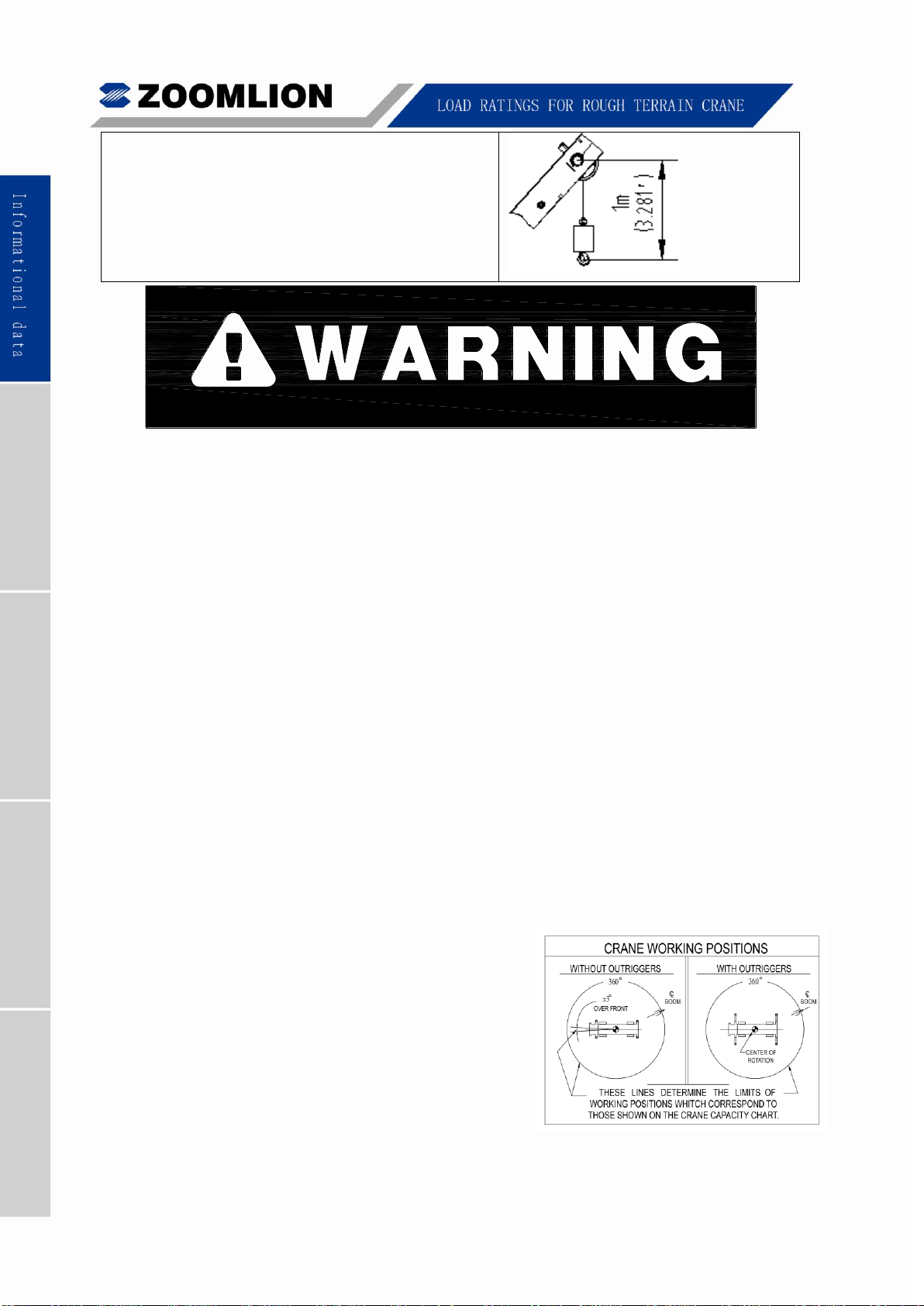
3. WORKING AREA – Areas measured in a
circular arc about the centerline of rotation as
shown in the diagram.
4. FREELY SUSPENDED LOAD – Load hanging
free with no direct external force applied except
by the hoist rope.
5. SIDE LOAD – Horizontal force applied to the lifted load either on the ground or in the
air;
6. EXTRA-CAUTION ZONE – Tipping can occur with some boom/jib combinations at
01 - 2 RT75 Rough Terrain Crane
Page 12
radii within this area without any load on the hook.
7. BOOM SIDE OF CRANE – The side of the crane over which the boom is positioned
when in an OVER SIDE working position.
1.6 SET-UP
1. Crane load ratings are based on the crane being leveled and standing on a firm and
uniform supporting surface.
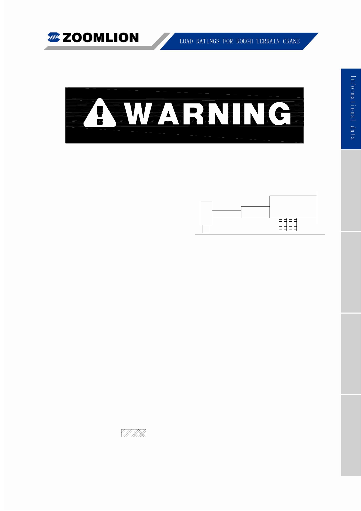
2. Crane load ratings on outriggers are
based on all outrigger beams being fully
extended / retracted, or in the case of
partial extension ratings mechanically
pinned in the appropriate position, and
the tires raised free of the supporting
surface.
3. Crane load ratings on tires depend on appropriate inflation pressure and the tire
conditions. Caution must be exercised when increasing air pressures in tires. Consult
Operator’s Manual for precautions.
4. Consult appropriate section of the Operator’s Manual for more exact description of
hoist line reeving.
5. The use of more parts of line than required by the load may result in having insufficient
rope to allow the hook block to reach the ground.
6. Properly maintained wire rope is essential for safe crane operation. Consult
Operator’s Manual for proper maintenance and inspection requirements.
7. When spin-resistant wire rope is used, the allowable rope loading shall be the
breaking strength divided by five (5), unless otherwise specified by the wire rope
manufacturer.
1.7 OPERATION
1. CRANE LOAD RATINGS MUST NOT BE EXCEEDED. DO NOT ATTEMPT TO TIP
THE CRANE TO DETERMINE ALLOWABLE LOADS.
2. When either radius or boom length, or both, are between listed values, the smaller of
the two listed load ratings shall be used.
3. Do not operate at longer radii than those listed on the applicable Lift Chart (cross
hatched areas shown on range diagrams) as tipping can occur without a
load on the hook.
4. The boom angles shown on the Lift Charts give an approximation of the operating
radius for a specified boom length. The boom angle, before loading, should be greater
to account for boom deflection. It may be necessary to retract the boom if maximum
RT75 Rough Terrain Crane 01 - 3
Page 13
boom angle is insufficient to maintain rated radius.
5. All telescopic sections must be extended synchronically.
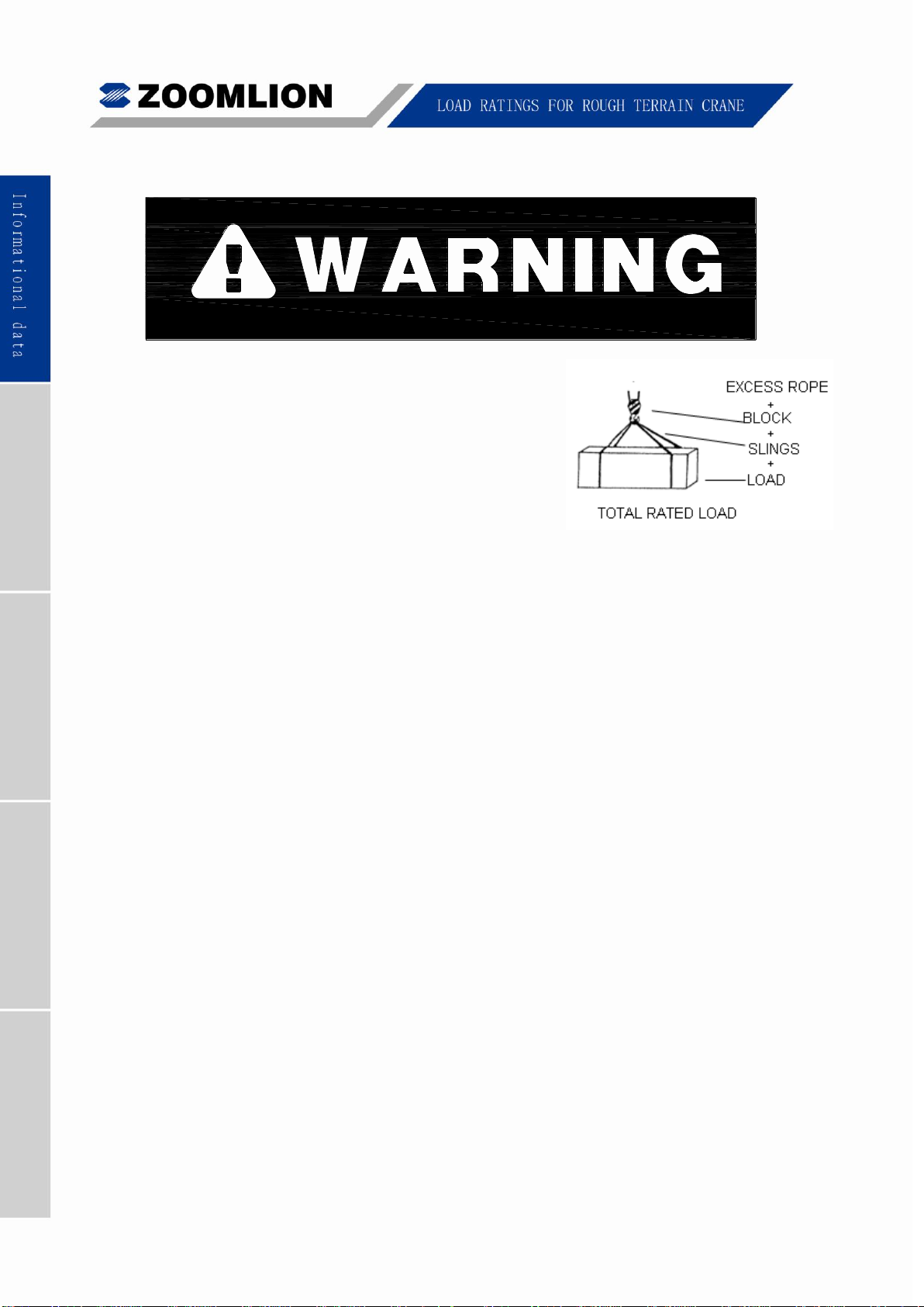
6. Rated loads include the weight of hook block, slings,
and auxiliary lifting devices. Their weights shall be
subtracted from the listed rated load to obtain the
net load that can be lifted.
7. When lifting over the jib, the weight of any hood
block, slings, and auxiliary lifting devices at the
boom head must be added to the load.
8. Rated lifting capacities are based on correct reeving. Deductions must be made for
excessive reeving. Any reeving over the minimum required, (see Hoist Tackle Chart),
is considered excessive and must be accounted for. Deduct for each meter of
excessive wire rope before attempting to lift a load.
9. When jibs are erected but unused, add three (3) times the weight of jib, any hook
block, slings, and auxiliary lifting devices at the jib head to the load (jib weight: 952 kg
(2099 lbs)).
10. Rated loads do not exceed 85% on outriggers or 75% on tires, of the tipping load as
determined by ASME/ANSI B30.5.
11. Rated loads are based on freely suspended loads. No attempt shall be made to drag a
load horizontally on the ground in any direction.
12. The user shall operate at reduced ratings to allow for adverse job conditions, such as:
soft or uneven ground, out of level conditions, high winds, side loads, pendulum action,
jerking or sudden stopping off loads, hazardous conditions, experience of personnel,
two-machine lifts, traveling with loads, electric wires, etc, (side pull on boom or jib is
hazardous). If wind speed is higher than the maximum permissible value (45 ft/s (13.8
m/s), grade 6) or it is fulminous during crane operation, stop working and completely
retract the boom and place it on the boom support for traveling.
13. Load ratings are dependent upon the crane being maintained according to
manufacturer’s specifications.
14. It is recommended that load handling devices, including hooks, and hook blocks, be
kept away from boom head at all times.
01 - 4 RT75 Rough Terrain Crane
Page 14

Page 15

Page 16

2.1 MAIN BOOM RATED LOADS
Rated loads on outriggers fully extended - 360°
(Rated load unit: Kg)
Working
Radius
(mm)
Boom Length (mm)
Working
Radius
(mm)
12500
16214
19929
23643
27357
31071
34786
38500
3000
75000
44860
3000
3500
75000
44860
3500
4000
68400
44860
4000
4500
61650
44860
34450
4500
5000
55950
44860
32950
5000
5500
51100
43550
31590
24700
5500
6000
46900
42050
30340
23750
6000
6500
43200
40650
29200
22850
19500
6500
7000
39990
39400
28150
22050
18850
7000
7500
35420
36350
27200
21300
18200
15740
7500
8000
30780
31650
26300
20600
17600
15240
8000
9000
24120
24890
24650
19350
16550
14350
12300
9000
10000
19590
20260
20550
18250
15590
13600
11700
10600
10000
11000
16900
17170
17250
14800
12850
11150
10150
11000
12000
14360
14610
14860
14050
12250
10600
9700
12000
14000
10800
10990
11210
11270
11150
9750
8450
14000
16000
8570
8750
8810
8970
8980
7400
16000
18000
7000
7050
7190
7200
6550
18000
20000
5700
5730
5850
5860
5850
20000
22000
4720
4820
4830
4920
22000
24000
3940
4000
4010
4090
24000
26000
3340
3330
3410
26000
28000
2810
2780
2840
28000
30000
2330
2370
30000
32000
1970
1970
32000
34000
1630
34000
36000
1370
36000
USE THIS CHART ONLY WHEN ALL OUTRIGGERS ARE FULLY EXTENDED
RT75 Rough Terrain Crane 02 - 1
Page 17

Rated loads on outriggers fully extended - 360°
(Rated load unit: lb)
Working
Radius
(ft)
Boom Length (ft)
Working
Radius
(ft)
41
53.2
65.4
77.6
89.8
101.9
114.1
126.3
10
165000
98900
10
12
162250
98900
12
15
133760
98900
75350
58740
15
20
101510
91960
66330
51810
44220
20
25
75240
77250
59290
46530
39710
34320
29150
25
30
51400
53060
53740
42240
36080
31350
26840
24310
30
35
39400
40020
38720
33110
28820
24860
22660
35
40
30660
31220
31770
30580
26730
23210
21230
40
45
24660
25120
25610
25750
24860
21670
18920
45
50
20660
21090
21220
21580
20350
17050
50
55
17300
17640
17760
18100
18120
15510
55
60
14940
15040
15350
15370
14190
60
65
12780
12850
13130
13150
12980
65
70
11100
11060
11300
11330
11540
70
75
9590
9780
9800
10000
75
80
8390
8500
8510
8690
80
85
7410
7400
7560
85
90
6490
6450
6590
90
95
5630
5740
95
100
4920
4990
100
105
4340
4340
105
110
3760
110
115
3270
115
02 - 2 RT75 Rough Terrain Crane
Page 18

SET-UP
1. Crane load ratings are based on the crane being leveled and standing on a firm and uniform
supporting surface.
2. Crane load ratings on outriggers are based on all outrigger beams being fully extended /
retracted, or in the case of partial extension ratings mechanically pinned in the appropriated
position, and the tyres raised free of the supporting surface.
OPERATION
1. CRANE LOAD RATINGS MUST NOT BE EXCEEDED. NO ATTEMPT TO TIP THE CRANE TO
DETERMINE ALLOWABLE LOADS.
2. When either radius or boom length, or both, are between listed values, the smaller of the two
listed load ratings shall be used.
3. EXTRA-CAUTION ZONE – Tipping can occur with some boom/jib combinations at radii within
this area without any load on the hook.
4. The boom angles shown on the Lift Charts give an approximation of the operation radius for a
specified boom length. The boom angle, before loading, should be greater to account for boom
deflection. It may be necessary to retract the boom if maximum boom angle is insufficient to
maintain rated radius.
5. Rated Loads include the weight of hook block, slings and auxiliary lifting devices. Their weights
shall be subtracted from the listed rated load to obtain the net load that can be lifted. Rated lift
ratings are based on correct reeving. Deductions must be made for excessive reeving. Any
reeving over the minimum is considered excessive. Deduct for each foot of excessive wire rope
before attempting to lift a load. See HOIST TACKLE CHART for rope information.
6. All telescopic sections must be extended synchronically.
RT75 Rough Terrain Crane 02 - 3
Page 19

Lift Height on Outriggers Fully Extended
02 - 4 RT75 Rough Terrain Crane
Page 20

2.2 10 M (33 ft)JIB RATED LOADS
10 m jib rated loads - 360°
(Rated load unit: kg Working radius unit: mm)
Boom
Angle
(º)
0º Offset
20º Offset
40º Offset
Working
Radius
(mm)
360º (kg)
Working
Radius
(mm)
360º (kg)
Working
Radius
(mm)
360º(kg)
76
9634
6000
12459
3050
14684
1990
74
11269
5800
14049
2850
16197
1890
72
12888
5600
15619
2700
17689
1850
70
14489
5050
17168
2550
19156
1800
68
16070
4500
18693
2450
20597
1750
66
17628
3990
20192
2350
22010
1700
64
19163
3600
21665
2250
23394
1650
62
20671
3250
23108
2150
24747
1650
60
22152
2950
24521
2050
26068
1600
58
23603
2700
25902
1990
27354
1600
56
25023
2450
27248
1940
28604
1550
54
26410
2250
28558
1850
29816
1550
52
27762
2100
29832
1800
30990
1500
50
29078
1890
31066
1650
32124
1500
48
30356
1750
32260
1550
33215
1450
46
31594
1630
33412
1450
34264
1350
44
32791
1440
34521
1350
35269
1300
42
33946
1270
35585
1210
36228
1180
40
35057
1120
36603
1070
37140
1040
38
36122
990
37574
940
38004
920
USE THIS CHART ONLY WHEN ALL OUTRIGGERS ARE FULLY EXTENDED
USE THIS CHART ONLY WHEN JIB SECTION 2 IS NOT PULLED OUT FROM JIB SECTION 1
RT75 Rough Terrain Crane 02 - 5
Page 21

33 ft jib rated loads - 360°
(Rated load unit: lb Working radius unit: ft)
Boom
Angle
(º)
0º Offset
20º Offset
40º Offset
Working
Radius
(ft)
360º (lb)
Working
Radius
(ft)
360º (lb)
Working
Radius
(ft)
360º(lb)
76
31
13200
40
6710
48
4400
74
36
12780
46
6270
53
4180
72
42
12320
51
5940
58
4070
70
47
11110
56
5610
62
3960
68
52
9900
61
5390
67
3850
66
57
8800
66
5170
72
3740
64
62
7920
71
4950
76
3630
62
67
7150
75
4730
81
3630
60
72
6490
80
4510
85
3520
58
77
5940
84
4400
89
3520
56
82
5390
89
4290
93
3410
54
86
4950
93
4070
97
3410
52
91
4620
97
3960
101
3300
50
95
4180
101
3630
105
3300
48
99
3850
105
3410
108
3190
46
103
3590
109
3190
112
2970
44
107
3180
113
2970
115
2860
42
111
2810
116
2660
118
2600
40
115
2470
120
2350
121
2300
38
118
2180
123
2080
124
2040
02 - 6 RT75 Rough Terrain Crane
Page 22

SET-UP
1. Crane load ratings are based on the crane being leveled and standing on a firm and uniform
supporting surface.
2. Crane load ratings on outriggers are based on all outrigger beams being fully extended /
retracted, or in the case of partial extension ratings mechanically pinned in the appropriate
position, and the tyres raised free of the supporting surface.
OPERATION
1. CRANE LOAD RATINGS MUST NOT BE EXCEEDED. NO ATTEMPT TO TIP THE CRANE TO
DETERMINE ALLOWABLE LOADS.
2. When either radius or boom length, or both, are between listed values, the smaller of the two
listed load ratings shall be used.
3. EXTRA-CAUTION ZONE – Tipping can occur with some boom/jib combinations at radii within
this area without any load on the hook.
4. The boom angles shown on the Lift Charts give an approximation of the operation radius for a
specified boom length. The boom angle, before loading, should be greater to account for boom
deflection. It may be necessary to retract the boom if maximum boom angle is insufficient to
maintain rated radius.
5. Rated Loads include the weight of hook block, slings and auxiliary lifting devices. Their weights
shall be subtracted from the listed rated load to obtain the net load that can be lifted. Rated lift
ratings are based on correct reeving. Deductions must be made for excessive reeving. Any
reeving over the minimum is considered excessive. Deduct for each foot of excessive wire rope
before attempting to lift a load. See HOIST TACKLE CHART for rope information.
6. When lifting over the jib, the weight of any hook block, slings, and any auxiliary lifting devices at
the boom head must be added to the load.
7. For all boom lengths less than the maximum with the jib erected, the rated loads are determined
by boom angle only in the appropriate column.
8. For all boom lengths less than the listed boom length, the rated load is to be determined by boom
angle.
RT75 Rough Terrain Crane 02 - 7
Page 23

Lift Height on Jib Section 1 Erected
02 - 8 RT75 Rough Terrain Crane
Page 24

2.3 17 M(56 ft) JIB RATED LOADS
17 m jib rated loads - 360°
(Rated load unit: kg Working radius unit: mm)
Boom
Angle
(º)
0º Offset
20º Offset
40º Offset
Working
Radius
(mm)
360º (kg)
Working
Radius
(mm)
360º (kg)
Working
Radius
(mm)
360º (kg)
76
11327
3500
16372
1650
20345
1050
74
13198
3350
18162
1550
21999
990
72
15051
3000
19927
1450
23623
990
70
16883
2700
21666
1400
25216
940
68
18691
2450
23375
1300
26775
900
66
20475
2250
25053
1250
28300
900
64
22230
2100
26699
1200
29787
850
62
23956
1940
28309
1150
31235
850
60
25651
1800
29882
1100
32643
800
58
27311
1700
31416
1050
34009
800
56
28936
1550
32909
990
35330
800
54
30523
1500
34360
940
36606
750
52
32070
1400
35766
940
37835
750
50
33576
1250
37126
900
39015
750
48
35038
1150
38438
850
40145
750
46
36455
1050
39701
850
41224
700
44
37825
940
40913
800
42249
700
42
39146
900
42073
750
43221
650
40
40417
800
43179
650
44138
650
38
41636
750
44229
600
44998
600
USE THIS CHART ONLY WHEN ALL OUTRIGGERS ARE FULLY EXTENDED
USE THIS CHART WHEN JIB SECTION 2 IS PULLED OUT FROM JIB SECTION 1
RT75 Rough Terrain Crane 02 - 9
Page 25

56 ft jib rated loads - 360°
(Rated load unit: lb Working radius unit: ft)
Boom
Angle
(º)
0º Offset
20º Offset
40º Offset
Working
Radius
(ft)
360º (lb)
Working
Radius
(ft)
360º (lb)
Working
Radius
(ft)
360º (lb)
76
37
7710
53
3630
66
2310
74
43
7370
59
3410
72
2200
72
49
6600
65
3190
77
2200
70
55
5940
71
3080
82
2090
68
61
5390
76
2860
87
1980
66
67
4950
82
2750
92
1980
64
72
4620
87
2640
97
1870
62
78
4290
92
2530
102
1870
60
84
3960
98
2420
107
1760
58
89
3740
103
2310
111
1760
56
94
3410
107
2200
115
1760
54
100
3300
112
2090
120
1650
52
105
3080
117
2090
124
1650
50
110
2750
121
1980
128
1650
48
114
2530
126
1870
131
1650
46
119
2310
130
1870
135
1540
44
124
2090
134
1760
138
1540
42
128
1980
138
1650
141
1430
40
132
1760
141
1430
144
1430
38
136
1650
145
1320
147
1320
SET-UP
a) Crane load ratings are based on the crane being leveled and standing on a firm and uniform
supporting surface.
b) Crane load ratings on outriggers are based on all outriggers beams being fully extended /
retracted, or in the case of partial extension ratings mechanically pinned in the appropriate
position, and the tyres raised free of the supporting surface.
02 - 10 RT75 Rough Terrain Crane
Page 26

OPERATION
1. CRANE LOAD RATINGS MUST NOT BE EXCEEDED. NO ATTEMPT TO TIP THE CRANE TO
DETERMINE ALLOWABLE LOADS.
2. When either radius or boom length, or both, are between listed values, the smaller of the two
listed load ratings shall be used.
3. EXTRA-CAUTION ZONE – Tipping can occur with some boom/jib combinations at radii within
this area without any load on the hook.
4. The boom angles shown on the Lift Chart give an approximation of the operation radius for a
specified boom length. The boom angle, before loading, should be greater to account for boom
deflection. It may be necessary to retract the boom if maximum boom angle is insufficient to
maintain rated radius.
5. Rated Loads include the weight of hook block, slings and auxiliary lifting devices. Their weights
shall be subtracted from the listed rated load to obtain the net load that can be lifted. Rated lift
ratings are based on correct reeving. Deductions must be made for excessive reeving. Any
reeving over the minimum is considered excessive. Deduct for each foot of excessive wire rope
before attempting to lift a load. See HOIST TACKLE CHART for rope information.
6. When lifting over the jib, the weight of any hook block, slings, and any auxiliary lifting devices at
the boom head must be added to the load.
7. For all boom lengths less than the maximum with the jib erected, the rated loads are determined
by boom angle only in the appropriate column.
8. For all boom lengths less than the listed boom length, the rated load is to be determined by boom
angle.
RT75 Rough Terrain Crane 02 - 11
Page 27

Lift Height on Jib Section 2 Erected
02 - 12 RT75 Rough Terrain Crane
Page 28

Page 29

Page 30

3.1 MAIN BOOM RATED LOADS
Rated loads on outriggers pinned in mid-position - 360°
(Rated load unit: kg)
Working
Radius
(mm)
Boom Length (mm)
Working
Radius
(mm)
12500
16214
19929
23643
27357
31071
34786
38500
3000
75000
44860
3000
3500
68800
44860
3500
4000
61100
44860
4000
4500
54750
44860
34450
4500
5000
44400
44860
32950
5000
5500
35960
36910
31590
24700
5500
6000
29980
30850
30340
23750
6000
6500
25530
26340
26640
22850
19500
6500
7000
22090
22850
23140
22050
18850
7000
7500
19340
20070
20350
20630
18200
15740
7500
8000
17110
17800
18070
18350
17600
15240
8000
9000
13690
14330
14590
14840
14890
14350
12300
9000
10000
11220
11800
12040
12290
12340
12530
11700
10600
10000
11000
9870
10110
10340
10390
10570
10580
10150
11000
12000
8360
8590
8810
8860
9040
9040
9120
12000
14000
6190
6360
6560
6620
6770
6780
6870
14000
16000
4830
4990
5050
5190
5200
5300
16000
18000
3850
3890
4030
4040
4130
18000
20000
3000
3020
3140
3150
3240
20000
22000
2340
2440
2450
2540
22000
24000
1820
1880
1890
1970
24000
26000
1430
1430
1500
26000
28000
1080
1050
1110
28000
USE THIS CHART WHEN ALL OUTRIGGERS ARE PINNED IN THE MID-POSITION
RT75 Rough Terrain Crane 03 - 1
Page 31

Rated loads on outriggers pinned in mid-position - 360°
(Rated load unit: lb)
Working
Radius
(ft)
Boom Length (ft)
Working
Radius
(ft)
41
53.2
65.4
77.6
89.8
101.9
114.1
126.3
10
165000
98900
10
12
145640
98900
12
15
118690
98900
75350
58740
15
20
63870
65760
66330
51810
44220
20
25
41290
42870
43470
44100
39710
34320
29150
25
30
29240
30620
31180
31750
31860
31350
26840
24310
30
35
23010
23540
24060
24180
24570
24590
22660
35
40
17850
18340
18820
18940
19310
19330
19500
40
45
14180
14590
15030
15150
15500
15520
15720
45
50
11780
12170
12290
12620
12640
12850
50
55
9630
9940
10050
10360
10380
10600
55
60
8170
8260
8550
8570
8790
60
65
6750
6810
7070
7090
7300
65
70
5650
5620
5840
5860
6060
70
75
4630
4810
4830
5010
75
80
3840
3940
3950
4120
80
85
3200
3190
3340
85
90
2570
2540
2670
90
SET-UP
1. Crane load ratings are based on the crane being leveled and standing on a firm and uniform
supporting surface.
2. Crane load ratings on outriggers are based on all outrigger beams being fully extended /
retracted, or partial extension ratings mechanically pinned in the appropriated position, and
the tyres raised free of the supporting surface.
OPERATION
1. CRANE LOAD RATINGS MUST NOT BE EXCEEDED. NO ATTEMPT TO TIP THE CRANE
TO DETERMINE ALLOWABLE LOADS.
2. When either radius or boom length, or both, are between listed values, the smaller of the two
listed load ratings shall be used.
3. EXTRA-CAUTION ZONE – Tipping can occur with some boom/jib combinations at radii within
this area without any load on the hook.
4. The boom angles shown on the Lift Charts give an approximation of the operation radius for a
specified boom length. The boom angle, before loading, should be greater to account for
boom deflection. It may be necessary to retract the boom if maximum boom angle is
insufficient to maintain rated radius.
03 - 2 RT75 Rough Terrain Crane
Page 32

5. Rated Loads include the weight of hook block, slings and auxiliary lifting devices. Their
weights shall be subtracted from the listed rated load to obtain the net load that can be lifted.
Rated lifting capacities are based on correct reeving. Deductions must be made for excessive
reeving. Any reeving over the minimum is considered excessive. Deduct for each foot of
excessive wire rope before attempting to lift a load. See HOIST TACKLE CHART for rope
information.
6. All telescopic sections must be extended synchronously.
Lift Height on Outriggers Pinned in the Mid-position
RT75 Rough Terrain Crane 03 - 3
Page 33

Page 34

Chapter 4 Lifts with outrigger beams
fully retracted
Page 35

Page 36

LOAD RATINGS FOR ROUGH TERRAIN CRANE
4.1 MAIN BOOM RATED LOADS
USE THIS CHART WHEN ALL OUTRIGGERS ARE FULLY RETRACTED
Rated loads on outriggers are fully retracted - 360°
(Rated load unit: kg)
Working
Radius
(mm)
Boom Length (mm)
12500 16214 19929 23643 27357 31071 34786 38500
Working
Radius
(mm)
3000 51050 44860 3000
3500 37080 38020 3500
4000 28670 29510 4000
4500 23060 23840 24080 4500
5000 19060 19780 20020 5000
5500 16050 16740 16970 17240 5500
6000 13710 14370 14600 14860 6000
6500 11840 12480 12710 12950 12980 6500
7000 10310 10930 11150 11390 11430 7000
7500 9040 9640 9860 10100 10130 10310 7500
8000 7970 8550 8770 9000 9040 9210 8000
9000 6260 6810 7020 7250 7290 7460 7460 9000
10000 4980 5480 5690 5910 5950 6110 6120 6190 10000
11000 4440 4650 4850 4900 5060 5060 5130 11000
12000 3600 3800 4000 4050 4200 4210 4280 12000
14000 2380 2540 2710 2760 2910 2920 3000 14000
beams fully retracted
Lifts with outrigger
16000 1640 1800 1840 1980 1990 2070 16000
18000 1110 1150 1280 1290 1380 18000
RT75 Rough Terrain Crane 04 - 1
Page 37

LOAD RATINGS FOR ROUGH TERRAIN CRANE
Rated loads on outriggers are fully retracted - 360°
(Rated load unit: lb)
Working
Radius
(ft)
Boom Length (ft)
41 53.2 65.4 77.6 89.8 101.9 114.1 126.3
Working
Radius
(ft)
10 108510 98900 10
12 74820 76810 12
15 49300 50980 51520 52150 15
20 29310 30750 31260 31810 31870 20
25 19300 20600 21090 21600 21680 22070 22070 25
30 13330 14510 14990 15470 15570 15930 15940 16100 30
35 10470 10930 11390 11490 11850 11850 12010 35
40 7620 8060 8490 8590 8930 8940 9090 40
45 5540 5920 6320 6430 6750 6770 6940 45
50 4290 4650 4760 5060 5080 5270 50
55 3040 3330 3430 3720 3740 3940 55
60 2280 2360 2630 2650 2850 60
SET-UP
beams fully retracted
1. Crane load ratings are based on the crane bei ng leveled and standing on a firm and uniform
supporting surface.
2. Crane load ratings on outriggers are based on all outrigger beams being fully extended /
retracted, or partial extension ratings mechanically pinned in the appropriated position, and
the tyres raised free of the supporting surface.
OPERATION
Lifts w ith outrigger
1. CRANE LOAD RATINGS MUST NOT BE EXCEEDED. NO ATTEMPT TO TIP THE CRANE
TO DETERMINE ALLOWABLE LOADS.
2. When either radius or bo om length, or both, are between listed values, the smaller of the two
listed load ratings shall be used.
3. EXTRA-CAUTION ZONE – Tipping can occur with some boom/jib combinations at radii within
this area without any load on the hook.
4. The boom angles shown on the Lift Charts give an approximation of the operation radius for a
specified boom length. The boom angle, before loading, should be greater to account for
boom deflection. It may be necessary to retract the boom if maximum boom angle is
insufficient to maintain rated radius.
5. Rated Loads include the weight of hook block, slings and auxiliary lifting devices. Their
weights shall be subtracted from the listed rated load to obtain the net load that can be lifted.
Rated lifting capacities are based on correct reeving. Deductions must be made for excessive
reeving. Any reeving over the minimum is considered excessive. Deduct for each foot of
excessive wire rope before attempting to lift a load. See HOIST TACKLE CHART for rope
information.
04 - 2 RT75 Rough Terrain Crane
Page 38

LOAD RATINGS FOR ROUGH TERRAIN CRANE
6. All telescopic sections must be extended synchronously.
beams fully retracted
Lifts with outrigger
Lift Height on Outriggers Fully Retracted
RT75 Rough Terrain Crane 04 - 3
Page 39

Page 40

Page 41

Page 42

5.1MAINBOOMRATEDLOADS
Ratedloadsontires
(Ratedloadunit:kg)
BoomLengthof
Working
Radius
(mm)
3000 66.82 17360 27250 20200 74.15 17900 27520 20600
3500 63.79 14830 24200 17830 72.18 15360 24650 18250
4000 60.67 12800 21710 15890 70.18 13300 22150 16350
4500 57.43 11150 19580 14260 68.16 11700 20040 14710
5000 54.05 9790 17780 12850 66.10 10290 18210 13330
5500 50.48 8670 16220 11700 64.00 9140 16690 12120
6000 46.69 7670 14920 10640 61.86 8160 15350 11070
6500 42.61 6850 13560 9690 59.67 7320 14160 10140
7000 38.11 6110 11890 8920 57.42 6600 12460 9330
7500 33.01 5320 10520 8200 55.11 5850 11060 8630
8000 26.90 4620 9380 7510 52.72 5130 9900 7970
8500 18.51 4020 8420 6960 50.24 4500 8920 7390
Boom
Angle
(º)
10800
360
(º)
mm BoomLengthof
Stationary
overFront
Pick
&
Carry
Boom
Angle
(º)
360
(º)
15440
Stationary
overFront
mm
&Carry
Pick
9000 0 3720 7940 6690 47.66 3960 8080 6850
9500 44.96 3490 7350 6330
10000 42.11 3070 6710 5690
10500 39.07 2700 6160 5130
11000 35.79 2370 5660 4640
11500 32.19 2080 5220 4200
12000 28.13 1810 4830 3810
12500 23.33 1570 4470 3460
13000 17.05 1360 4160 3150
13500 0 1240 3940 2940
RT75RoughTerrainCrane 05-
1
Page 43

Ratedloadsontires
(Ratedloadunit:kg)
BoomLengthof20080mm BoomLengthof24720mm
Working
Radius
(mm)
3000 77.91
3500 76.44
4000 74.95
4500 73.45 11970 20280 14950
5000 71.93 10630 18500 13570
5500 70.41 9460 16950 12370
6000 68.86 8460 15580 11350 73.02 8750 15790 11560
6500 67.30 7610 14420 10390 71.79 7890 14610 10640
7000 65.71 6880 12800 9620 70.55 7150 13070 9800
7500 64.11 6170 11390 8860 69.30 6420 11650 9080
8000 62.48 5430 10210 8230 68.04 5680 10460 8440
8500 60.82 4800 9220 7640 66.77 5040 9460 7840
9000 59.13 4250 8370 7090 65.48 4490 8600 7330
9500 57.41 3770 7630 6600 64.18 4000 7860 6830
10000 55.66 3350 6980 5960 62.86 3570 7210 6180
10500 53.86 2970 6420 5390 61.53 3190 6630 5610
11000 52.01 2630 5910 4890 60.18 2840 6120 5100
11500 50.12 2320 5460 4440 58.81 2530 5660 4640
12000 48.16 2050 5060 4030 57.41 2250 5250 4230
12500 46.14 1800 4690 3670 56.00 2000 4880 3860
13000 44.04 1570 4360 3340 54.55 1760 4550 3530
13500 41.85 1360 4060 3040 53.08 1550 4240 3220
14000 39.55 1170 3780 2760 51.58 1350 3960 2940
14500 37.13 3530 2510 50.04 1170 3700 2680
15000 34.55 3300 2280 48.47 3460 2440
15500 31.77 3080 2060 46.85 3240 2220
16000 28.72 2880 1870 45.19 3040 2020
16500 25.31 2700 1690 43.47 2850 1830
17000 21.33 2540 1520 41.70 2670 1650
17500 16.31 2380 1370 39.85 2500 1490
18000 7.94 2250 1250 37.93 2350 1330
18500 0 2250 1250 35.91 2210 1190
Boom
Angle
(º)
360
(º)
Stationary
overFront
Pick
&Carry
Boom
Angle
(º)
360
(º)
Stationary
overFront
&Carry
Pick
05-
2
RT75RoughTerrainCrane
Page 44

Ratedloadsontires
(Ratedloadunit:lb)
BoomLengthof35ft BoomLengthof51ft
Working
Radius
(ft)
10 66.54 37620 59290 43890 73.97 38720 60170 44770
12 62.82 31160 51470 37880 71.56 32270 52360 38720
15 56.96 24080 42530 30930 67.87 25260 43510 31900
20 45.94 16540 32280 23000 61.45 17610 33220 23920
25 31.66 11320 22500 17620 54.54 12470 23680 18570
30 0 8200 17480 14720 46.90 8410 17290 14820
35 38.00 5700 13170 10920
40 26.40 3790 10310 8080
45 0 2720 8680 6470
Boom
Angle
(º)
360
(º)
Stationary
over
Front
Pick
&Carry
Boom
Angle
(º)
360
(º)
Stationary
over
Front
BoomLengthof66ft BoomLengthof81ft
Working
Radius
(ft)
Boom
Angle
(º)
360
(º)
Stationary
over
Front
Pick
&Carry
Working
Radius
(ft)
Boom
Angle
(º)
360
(º)
Stationary
Pick
&Carry
over
Front
10
12
15 73.24 25950 44020 32410
20 68.57 18270 33820 24520 72.78 18790 34270 24980
25 63.72 13160 24390 19160 69.00 13720 24960 19630
30 58.65 9040 17920 15330 65.11 9560 18430 15740
35 53.25 6270 13730 11480 61.08 6750 14200 11950
40 47.40 4290 10810 8560 56.87 4740 11240 9000
45 40.88 2810 8660 6420 52.44 3220 9060 6810
50 33.25 1670 7030 4790 47.70 2040 7380 5140
55 23.30 5750 3520 42.54 1110 6060 3820
60 4970 2760 36.78 4990 2760
65 30.02 4120 1890
RT75RoughTerrainCrane 05-
3
Page 45

SET-UP
leveled
appropriate
be
tires.
1. Craneloadratingsarebasedonthecranebeing
andstandingonafirmanduniformsupportingsurface.
2. Craneloadratingsontiresdependon
CRANE WORKING POSITIONS
WITHOUT OUTRIGGERS WITH OUTRIGGERS
360
±3
OVER FRONT
C
L
BOOM
360
inflationpressureandtirecondition.Cautionmust
exercised when increasing airpressures in
CENTER OF
ROTATION
Consult Operator’sManual forprecautions.
THESE LINES DETERMINE THE LIMITS OF
3. Useofjibisnotpermittedforpick-and-carryoperations.
WORKING POSITIONS WHITCH CORRESPOND TO
THOSE SHOWN ONTHE CRANE CAPACITY CHART.
SET-UP
1. Forpick-and-carryoperations,boommustbecenteredoverthefrontofthecranewith
swingandbrakelockengaged.Useminimumboompointheightandkeeploadcloseto
groundsurface.Travelmustbeonsmoothlevelsurface.
2. Theloadshouldberestrainedfromswinging.Noontireoperationwithjiberected.
OPERATION
1. CRANELOADRATINGSMUSTNOTBEEXCEEDED.NOATTEMPTTOTIPTHE
CRANETODETERMINEALLOWABLELOADS.
2. Whenradiusisbetweenlistedvalues,thesmallerofthetwolistedloadratingsshallbe
used;
C
L
BOOM
3. Donotoperateatlongerradiithanthoselistedontheapplicable LiftChart astippingcan
occurwithoutaloadonthehook.
4. Alltelescopicsectionsmustbeextendedsynchronously.
5. Withoutoutriggers,nevermaneuvertheboombeyondlistedloadradiiforapplicabletires
usedtoensurestability.
6. Creepspeediscranemovementoflessthan61m(200ft)in30-minutesperiodandnot
exceeding1.6KM/H(1MPH).
05-
4
RT75RoughTerrainCrane
Page 46

LiftHeigthonTires
RT75RoughTerrainCrane 05-
5
Page 47

Rated loads on tires
(Rated load unit: lb)
Working
Radius
(ft)
Boom Length of89.8 ft
Boom
Angle
(º)
360
(º)
Stationary
over Front
Pick
& Carry
20
74.4
22830
44220
34350
25
71.0
16400
35070
26910
30
67.6
11070
25600
21510
35
64.0
7500
19550
16450
40
60.3
4930
15360
12260
45
56.5
3010
12290
9190
50
52.5
——
9940
6850
55
48.3
——
8100
5010
60
43.7
——
6630
3540
65
38.6
——
5420
2340
70
32.9
——
4430
——
75
26.0
——
3610
——
80
16.4
——
2950
——
SET-UP
1. Crane load ratings are based on the crane being leveled and standing on a firm and uniform
supporting surface.
2. Crane load ratings on tires depend on appropriate inflation pressure and tire condition.
Caution must be exercised when increasing air pressures in tires. Consult Operator’s Manual
for precautions.
3. Use of jib is not permitted for pick-and-carry operations.
05 - 6 RT75 Rough Terrain Crane
Page 48

SET-UP
360
360
CRANE WORKING POSITIONS
WITHOUT OUTRIGGERS WITH OUTRIGGERS
BOOM
L
C
THESE LINES DETERMINE THE LIMITS OF
WORKING POSITIONS WHITCH CORRESPOND TO
THOSE SHOWN ONTHE CRANE CAPACITY CHART.
CENTER OF
ROTATION
OVER FRONT
BOOM
L
C
±3
1. For pick-and-carry operations, boom must be centered over the front of the crane with swing
and brake lock engaged. Use minimum boom point height and keep load close to ground
surface. Travel must be on smooth level surface.
2. The load should be restrained from swinging. No on tire operation with jib erected.
OPERATION
1. CRANE LOAD RATINGS MUST NOT BE EXCEEDED. NO ATTEMPT TO TIP THE CRANE
TO DETERMINE ALLOWABLE LOADS.
2. When radius is between listed values, the smaller of the two listed load ratings shall be used;
3. Do not operate at longer radii than those listed on the applicable Lift Chart as tipping can
occur without a load on the hook.
4. All telescopic sections must be extended synchronously.
5. Without outriggers, never maneuver the boom beyond listed load radii for applicable tires
used to ensure stability.
6. Creep speed is crane movement of less than 61 m in 30-minutes period and not exceeding
1.6 KM/H.
RT75 Rough Terrain Crane 05 - 7
Page 49

Lift Heigth on Tires
05 - 8 RT75 Rough Terrain Crane
 Loading...