

Page 1

LOAD CHART MANUAL FOR
RT55 ROUGH TERRAIN CRANE
Address:Quantang Indust=rial Park, 2nd Yuanda Road,
Changsha Economic and Technological Development
Zone, Hunan Province, China
Postcode: 410131
Website: www.zoomlion.com
Page 2

RT55 ROUGH TERRAIN CRANE
LOAD RATINGS
Edition 1
Dec. 2013
Page 3

Page 4

LOAD RATINGS FOR ROUGH TERRAIN CRANE
To owners, users and operators
Zoomlion Cranes appreciates your selection of the ZOOMLION Rough Terrain Crane
for your application.
No one should operate the crane unless they read and understand the information in
this manual.
When you follow the instructions in this manual, your crane can operate at MAXIMUM
EFFICIENCY.
The operator must keep this manual in the cab of the crane.
If there is anything in the manual that you do not understand, speak with us. We
(Zoomlion Cranes) are NOT responsible for damages from an operator who does not
obey the instructions in the OPERATOR’S MANUAL.
The OPERA T OR’S MANUAL is an important part of the crane. If the crane becomes the
property of a different person, make sure that the manual stays in the cab of the crane.
THANK YOU!
Mobile Crane Branch Company of ZOOMLION Heavy Industry Science and Technology
Co., Ltd.
Copyright
Under the copyright laws, this manual may not be copied, photocopied, reproduced,
translated, or reduced to any electronic medium or machine readable form, in whole or
part, without the prior written consent of Zoomlion Heavy Industry Science and
Technology Co., Ltd.
Copyright © 20XX, Zoomlion Heavy Industry Science and Technology Co., Ltd.
All rights reserved.
RT55 Rough Terrain Crane I
Page 5

LOAD RATINGS FOR ROUGH TERRAIN CRANE
Safety
Hazard Indicators
DANGER, WARNING, CAUTION, ATTENTION, NOTE, and IMPORTANT labels are on
signs and decals, and as you read this manual to show important instructions. In this
manual, DANGER, WARNING, and CAUTION labels are before the paragraph or item to
which they apply. ATTENTION, NOTE, and IMPORTANT follow the paragraph or item
they apply to. The markers are as follows:
Danger
Refers to a dangerous situation which, if you do not prevent, will cause death or
injury.
Refers to a possible dangerous situation which, if you do not prevent, could cause
death or injury.
Refers to a possible dangerous situation which, if you do not prevent, may cause
light or moderate injury.
Warning
Caution
Attention
Refers to a situation which, if you do not prevent, may cause property or equipment
damage.
Note
Refers to a tip or hint in the operation instructions.
Important
Emphasizes the importance of the data in this manual.
This symbol shows a step or procedure that is not approved and can cause a dangerous
situation.
II RT55 Rough Terrain Crane
Page 6

To Owners, Users and Operators ....................................................................................................... I
Safety . .................................................................................................................................................. II
1 Informational data ...................................................................................................................... 01-1
1.1 Hoist Tackle Chart ............................................................................................................... 01-1
1.2 Tire Inflation Chart ............................................................................................................... 01-1
1.3 Weights ................................................................................................................................ 01-2
1.4 Maximum outrigger float load .............................................................................................. 01-2
1.5 General ................................................................................................................................ 01-3
1.6 Definitions ............................................................................................................................ 01-3
1.7 Set-up .................................................................................................................................. 01-4
1.8 Operation ............................................................................................................................. 01-4
2 Lifts with outrigger beams fully extended . ............................................................................. 02-1
3 Lifts with outrigger beams at mid-position . ............................................................................ 03-1
4 Lifts with outrigger beams fully retracted ............................................................................... 04-1
5 Lifts on tires ............................................................................................................................... 05-1
RT55 Rough Terrain Crane III
Page 7

Page 8

Page 9

Page 10

MAXIMUM
LOAD (KG)
LOAD (LBS)
7 COMPACTED
1.1 HOIST TACKLE CHART
This chart only represents the maximum permissible hoist l ine load per parts of line. You must
refer to the proper Lift Charts for machine rated loads.
Table 01 – 1 Line Parts
MAXIMUM PERMISSIBLE HOIST LINE LOAD
LINE PARTS
PERMISSIBLE
HOIST LINE
1 2 3 4 5 6 7 8 9 10
5500 11000 16500 22000 27500 33000 38500 44000 49500 55000
MAXIMUM
PERMISSIBLE
HOIST LINE
12125 24250 36375 48500 60625 72750 84875 97000 109125 121250
Wire rope: 19NAT-15×K7-IWRC-1960Mpa(3/4″ROTATION RESISTANT 15×K
STRAND, GRADE 1960)
Weight: 160kg/100m (1.1LBS/FT) Minimum breaking strength: 31.1T (30.61TONS)
1.2 TIRE INFLATION CHART
Table 01 – 2 Tire Inflation Chart
RECOMMENDED TIRE PRESSURE
TIRE SIZE STATIONARY
26.50-25-32PR
580kpa(85 PSI) 580kpa(85 PSI) 450kpa(65 PSI)
CREEP(21/2MPH)
TRAVEL
RT55 Rough Terrain Crane 01 - 1
Page 11

1.3 WEIGHTS
Table 01 – 3 Weights
HOOK BLOCK WEIGHTS DIMENSIONS ARE FOR MAIN HOOK
AND AUXILIARY HOOKS.
Main hook weight: 650kg(1433 LBS)
Auxiliary hook weight: 120kg(265 LBS)
MACHINE EQUIPMENT
1. COUNTERWEIGHT: 5000kg(1102 LBS)。
2. OUTRIGGER SPREAD: 6.9 m(22.6 ft) from
center of outrigger float to center of outrigger
float across the longitudinal axis of the m achine;
6.9 m(22.6 ft) from center of outrigger float to
center of outrigger float across the transversal
axis of the machine
3. Powered boom length 10.8 m (35.43 ft) retracted
to 34 m (111.55ft) extended
4. Crane height 3.75m (12 ft-3.5 in), length 13.1m
(43 ft), width 3.3m (10 ft-10 in), wheelbase
3.95m (8 ft-6.6 in)
1.4 MAXIMUM OUTRIGGER FLOAT LOAD
When lifting loads shown in these capacity charts, no single float load will exceed 50000 kg
(88,000 lb).
01 - 2 RT55 Rough Terrain Crane
Page 12

1.5 GENERAL
1.5.1 Rated loads as shown on Lifting Charts pertain to this machine as originally
manufactured and equipped. Modifications to the machine or use of optional
equipment other than that specified can resul t in a reduction of capacity.
1.5.2 Construction equipment can be hazardous if improperly opera ted or maintained.
Operation and maintenance of this machine shall be in compliance with the
information in the Operator’s Manual supplied with this machine. If thes e manuals
are missing, order replacements from the manufacturer through your distributor.
1.5.3 These warnings do not constitute all of the operating conditions for the crane. The
operator and job site supervision must read the Operator’s Manual.
1.5.4 This crane and its load ratings are in accordance with ASME/ANSI B30.5.
1.6 DEFINITIONS
1.6.1. LOAD RADIUS – The horizontal distance from the axis of rotation before loading to
the center of the vertical hoist line or tackle with a load applied.
1.6.2. LOAD BOOM A NGLE – It is the angle between the boom base sec tion and the
horizontal, after lifting the rated load at the rated radius. The boom angle before
loading should be greater to account for deflections. The loaded boom angle
combined with the boom length give only
an approximation of the operating radius .
1.6.3. WORKING AREA – Areas measured in a
circular arc about the centerline of rotation
as shown in the diagram.
1.6.4. FREELY SUSPENDED LOAD – Load
hanging free with no direct external force
applied except by the hoist rope.
1.6.5. Side load – Horizontal force applied to the lifted load either on t he ground or in t he
air.
1.6.6. EXTRA-CAUTION ZONE – Tipping can occur with some boom/ jib combi nati ons at
radii within this area without any load on the hook.
1.6.7. BOOM SIDE OF CRANE – The side of the crane over which the boom is
positioned when in an OVER SIDE working posit i on.
RT55 Rough Terrain Crane 01 - 3
Page 13

1.7 SET-UP
1.7.1. Crane load r atings are based on the crane being leveled and standing on a firm
and uniform supporting surface.
1.7.2. Crane load r atings on outriggers are
based on all outrigger beams being
fully extended / retracted, or in the
case of partial extension ratings
mechanically pinned in the
appropriate position, and the tires
raised free of the supporting surface.
1.7.3. Crane load r atings on tires depend on appropriate inflation pressure and the tire
conditions. Caution must be exercised when increasing air pressures in tires.
Consult Operator’s Manual for precautions.
1.7.4. Consult appr opriat e sec t ion of the Operator’s Manual for more exact desc ripti on of
hoist line reeving.
1.7.5. The use of more parts of line than required by the load may result in having
insufficient rope to allow the hook block to reach the ground.
1.7.6. Properly maintained wire rope is essential for safe crane operation. Consult
Operator’s Manual for proper maintenance and inspection requirements.
1.7.7. When spin-resistant wire rope is used, the allowable rope loading shall be the
breaking strength divided by five (5), unless otherwise specified by the wire rope
manufacturer.
1.8 OPERATION
1.8.1. CRANE LOAD RATINGS MU ST N OT BE EX CEEDED. DO NOT ATTEMPT TO TIP
THE CRANE TO DETERMINE ALLOWABLE LOADS .
1.8.2. When either radius or boom length, or both, are between lis ted values , the smalle r
of the two listed load ratings shall be used.
1.8.3. Do not operat e at longer radii than those list ed on the applicable Lift Chart (cross
hatched areas shown on range diagrams) as tipping c an occur wit hout
a load on the hook.
1.8.4. The boom angles shown on the Lift Charts give an approximation of the operating
radius for a specified boom length. The boom angle, before loading, should be
01 - 4 RT55 Rough Terrain Crane
Page 14

greater to account for boom deflection. It may be necessary to ret ract the boom if
maximum boom angle is insufficient to maintain rated radius.
1.8.5. All telescopic sections must be extended synchronically.
1.8.6. Rated loads include the weight of hook block,
slings, and auxiliary lifting devices. Their weights
shall be subtracted from the listed rated load to
obtain the net load that can be lifted.
1.8.7. When lifting over the jib, the weight of any hood
block, slings, and auxiliary lifting devices at the
boom head must be added to the load.
1.8.8. Rated lifting capacities are based on correct reeving. Deductions must be made for
excessive reeving. Any reeving over the minimum required, (see Hoist Tackle
Chart), is considered excessive and mus t be accounted for. Deduct for each meter
of excessive wire rope before attempting to l ift a load.
1.8.9. When jibs are erec ted but unused, add three (3) times the weight of jib, any hook
block, slings, and auxiliary lifting devices at the jib head to the load (jib weight: 952
kg (2099 lbs)).
1.8.10. Rated loads do not excee d 85% on outriggers or 75% on tires, of the tipping load
as determined by ASME/ANSI B30.5.
1.8.11. Rated loads are based o n freely suspended loads. No attempt shall be made to
drag a load horizontally on the ground in any direction.
1.8.12. The user shall oper ate at reduced rat ings to al low for adv erse j ob conditi ons, such
as: soft or uneven ground, out of level conditions, high winds, side loads,
pendulum action, jerking or sudden stopping off loads, hazardous conditions,
experience of personnel, two-machine lifts, traveling with loads , electric wires, etc,
(side pull on boom or jib is hazardous). If wind speed is higher than t he maximum
permissible value (45 ft/s (13.8 m/s), grade 6) or it is fulminous during crane
operation, stop working and completely retract the boom and place it on the boom
support for traveling.
1.8.13. Load ratings are dependent upon the crane being maintained according to
manufacturer’s specif ic ations.
1.8.14. It is recommende d that load handling devices, including hooks , and hook blocks,
be kept away from boom head at all times.
RT55 Rough Terrain Crane 01 - 5
Page 15

Page 16

Page 17

Page 18

2.1 MAIN BOOM RATED LOADS
USE THIS CHART ONLY WHEN ALL OUTRIGGERS ARE FULLY EXTENDED
Rated loads on outriggers fully extended - 360°
(Rated load unit: Kg)
Working
Radius
(mm)
Boom Length (mm)
10080 15440 20080 24720 29360 34000
Working
Radius
(mm)
3000 55000 27200 3000
3500 51300 27200 3500
4000 47550 27200 4000
4500 43250 27200 26300 4500
5000 39200 27200 26300 5000
5500 35750 27200 26300 5500
6000 32790 27200 25300 20000 6000
6500 30240 27200 24300 19300
7000 27950 26450 23000 18650
7500 25670 25000 21800 18050 15290
8000 22510 23200 20700 17400 14750
8830 17460
6500
7000
7500
8000
8830
9000 18510 18750 15790 13850 10560 9000
10000 15250 15530 14500 12700 10560 10000
11000 12820 13100 13300 11700 10100 11000
12000 10960 11220 11410 10800 9350 12000
13000 9510 9730 9920 9930 8650 13000
13461 9030 13461
14000 8530 8700 8720 8040 14000
16000 6720 6860 6880 7040 16000
18000 5470 5540 5550 5700 18000
18096 5460 18096
20000 4540 4550 4680 20000
22000 3790 3780 3890 22000
22733 3610 22733
24000 3160 3260 24000
26000 2680 2740 26000
27371 2470 27371
28000 2310 28000
30000 1960 30000
32000 1700 32000
32009 1700 32009
RT55 Rough Terrain Crane 02 - 1
Page 19

Rated loads on outriggers fully extended - 360°
(Rated load unit: lb)
Working
Radius
(ft)
10 121000 60200 10
12 110110 60200 12
15 93830 60200 58190 15
20 71060 59400 51370 40810 20
25 52840 49720 43450 36520 31350 25
28 38380 28
30 38250 37290 31570 27610 23280 30
35 28750 29530 27610 24200 21120 35
40 22590 23260 23830 21450 18700 40
44 19110 44
35 51 66 81 96 112
Boom Length (ft)
Working
Radius
(ft)
45 18860 19370 19250 16720 45
50 15610 16070 16240 15070 50
55 13140 13530 13690 13640 55
59 11560 59
60 11520 11660 12060 60
65 9890 10020 10390 65
70 8570 8670 9010 70
74 7640 74
75 7540 7850 75
80 6580 6860 80
85 5780 6000 85
89 5220 89
90 5260 90
95 4620 95
100 4060 100
105 3600 105
02 - 2 RT55 Rough Terrain Crane
Page 20

SET-UP
1. Crane load ratings are based on the crane being leveled and standing on a firm and
uniform supporting surface.
2. Crane load ratings on outriggers are based on all outrigger beams being fully extended /
retracted, or in the case of partial extension ratings mechanically pinned in the
appropriated position, and the tires raised free of the supporting surface.
OPERATION
1. CRANE LOAD RATINGS MUST NOT BE EXCEEDED. NO ATTEMPT TO TIP THE
CRANE TO DETERMINE ALLOWABLE LOADS.
2. When either radius or boom length, or both, are between listed values, the smaller of the
two listed load ratings shall be used.
3. EXTRA-CAUTION ZONE – Tipping can occur with some boom/jib combinations at radii
within this area without any load on the hook.
4. The boom angles shown on the Lift Charts give an approximation of the operation radius
for a specified boom length. The boom angle, before loading, should be greater to account
for boom deflection. It may be necessary to retract the boom if maximum boom angle is
insufficient to maintain rated radius.
5. Rated Loads include the weight of hook block, slings and auxiliary lifting devices. Their
weights shall be subtracted from the listed rated load to obtain the net load that can be
lifted. Rated lift ratings are based on correct reeving. Deductions must be made for
excessive reeving. Any reeving over the minimum is considered excessive. Deduct for
each foot of excessive wire rope before attempting to lift a load. See HOIST TACKLE
CHART for rope information.
6. All telescopic sections must be extended synchronically.
RT55 Rough Terrain Crane 02 - 3
Page 21

Lift Height on Outriggers Fully Extended
02 - 4 RT55 Rough Terrain Crane
Page 22

2.2 10 M JIB LIFTING CAPACITIES
USE THIS CHART ONLY WHEN ALL OUTRIGGERS ARE FULLY EXTENDED
USE THIS CHART ONLY WHEN JIB SECTION 2 IS NOT PULLED OUT FROM JIB
SECTION 1
10 m jib lifting capacities - 360°
(Lifting capacity unit: kg Working radius unit: mm)
Derricking
Angle
(º)
0º Offset 20º Offset 40º Offset
Working
Radius
(mm)
360º
(kg)
Working
Radius
(mm)
360º
(kg)
Working
Radius
(mm)
360º
(kg)
76 8645 5500 11471 2850 13695 1940
74 10129 5050 12909 2700 15057 1890
72 11598 4600 14329 2550 16398 1850
70 13050 4200 15729 2450 17716 1800
68 14484 3840 17107 2350 19011 1750
66 15898 3500 18462 2250 20280 1700
64 17290 3200 19792 2150 21522 1700
62 18659 2900 21096 2050 22735 1650
60 20002 2700 22371 1990 23918 1600
58 21319 2500 23617 1940 25069 1600
56 22607 2300 24832 1850 26187 1550
54 23865 2150 26013 1800 27271 1550
52 25092 1990 27161 1750 28320 1550
50 26285 1850 28273 1650 29331 1500
48 27445 1750 29349 1550 30304 1450
46 28568 1600 30386 1450 31238 1400
44 29654 1500 31384 1400 32132 1350
42 30702 1420 32341 1300 32984 1250
40 31709 1290 33256 1230 33793 1200
38 32676 1180 34128 1120 34558 1100
RT55 Rough Terrain Crane 02 - 5
Page 23

10 m jib lifting capacities - 360°
(Lifting capacity unit: lb Working radius unit: ft)
Derricking
Angle
(º)
76 28 12100 37 6270 44 4290
74 33 11110 42 5940 49 4180
72 38 10120 47 5610 53 4070
70 42 9240 51 5390 58 3960
68 47 8470 56 5170 62 3850
66 52 7700 60 4950 66 3740
64 56 7040 64 4730 70 3740
62 61 6380 69 4510 74 3630
60 65 5940 73 4400 78 3520
58 69 5500 77 4290 82 3520
56 74 5060 81 4070 85 3410
54 78 4730 85 3960 89 3410
52 82 4400 89 3850 92 3410
0º Offset 20º Offset 40º Offset
Working
Radius
(ft)
360º
(lb)
Working
Radius
(ft)
360º
(lb)
Working
Radius
(ft)
360º
(lb)
50 86 4070 92 3630 96 3300
48 90 3850 96 3410 99 3190
46 93 3520 99 3190 102 3080
44 97 3300 102 3080 105 2970
42 100 3130 106 2860 108 2750
40 104 2850 109 2710 110 2640
38 107 2590 111 2480 113 2420
02 - 6 RT55 Rough Terrain Crane
Page 24

SET-UP
1. Crane load ratings are based on the crane being leveled and standing on a firm and
uniform supporting surface.
2. Crane load ratings on outriggers are based on all outriggers beams being fully extended /
retracted, or in the case of partial extension ratings mechanically pinned in the appropriate
position, and the tires raised free of the supporting surface.
OPERATION
1. CRANE LOAD RATINGS MUST NOT BE EXCEEDED. NO ATTEMPT TO TIP THE
CRANE TO DETERMINE ALLOWABLE LOADS.
2. When either radius or boom length, or both, are between listed values, the smaller of the
two listed load ratings shall be used.
3. EXTRA-CAUTION ZONE – Tipping can occur with some boom/jib combinations at radii
within this area without any load on the hook.
4. The boom angles shown on the Lift Chart give an approximation of the operation radius for
a specified boom length. The boom angle, before loading, should be greater to account for
boom deflection. It may be necessary to retract the boom if maximum boom angle is
insufficient to maintain rated radius.
5. Rated Loads include the weight of hook block, slings and auxiliary lifting devices. Their
weights shall be subtracted from the listed rated load to obtain the net load that can be
lifted. Rated lift ratings are based on correct reeving. Deductions must be made for
excessive reeving. Any reeving over the minimum is considered excessive. Deduct for
each foot of excessive wire rope before attempting to lift a load. See HOIST TACKLE
CHART for rope information.
6. When lifting over the jib, the weight of any hook block, slings, and any auxiliary lifting
devices at the boom head must be added to the load.
7. For all boom lengths less than the maximum with the jib erected, the rated loads are
determined by boom angle only in the appropriate column.
8. For all boom lengths less than the listed boom length, the rated load is to be determined by
boom angle.
RT55 Rough Terrain Crane 02 - 7
Page 25

Lift Height on Jib Section 1 Erected
02 - 8 RT55 Rough Terrain Crane
Page 26

2.3 17 M JIB RATED LOADS
USE THIS CHART ONLY WHEN ALL OUTRIGGERS ARE FULLY EXTENDED
USE THIS CHART WHEN JIB SECTION 2 IS PULLED OUT FROM JIB SECTION 1
17 m jib rated loads - 360°
(Rated load unit: kg Working radius unit: mm)
Boom
Angle
(º)
Working
0º Offset 20º Offset 40º Offset
Radius
(mm)
360º (kg)
Working
Radius
(mm)
360º (kg)
Working
Radius
(mm)
360º (kg)
76 10338 3150 15384 1550 19357 1050
74 12058 2800 17022 1450 20858 990
72 13760 2550 18637 1400 22332 940
70 15444 2300 20227 1300 23777 940
68 17106 2150 21789 1250 25190 900
66 18744 1940 23323 1200 26569 900
64 20358 1850 24826 1150 27914 850
62 21944 1700 26296 1100 29223 850
60 23501 1600 27732 1050 30493 800
58 25027 1500 29131 990 31724 800
56 26520 1400 30493 940 32914 800
54 27978 1350 31815 940 34061 750
52 29400 1250 33096 900 35165 750
50 30784 1200 34334 850 36223 750
48 32127 1100 35527 850 37234 750
46 33429 990 36675 800 38198 750
44 34688 940 37776 800 39112 750
42 35902 850 38829 750 39977 700
40 37070 800 39831 700 40791 650
38 38190 750 40783 650 41552 650
RT55 Rough Terrain Crane 02 - 9
Page 27

17 m jib lifting capacities - 360°
(Lifting capacity unit: lb Working radius unit: ft)
Boom
Angle
(º)
76 33 6930 50 3410 63 2310
74 39 6160 55 3190 68 2200
72 45 5610 61 3080 73 2090
70 50 5060 66 2860 78 2090
68 56 4730 71 2750 82 1980
66 61 4290 76 2640 87 1980
64 66 4070 81 2530 91 1870
62 71 3740 86 2420 95 1870
60 77 3520 90 2310 100 1760
58 82 3300 95 2200 104 1760
0º Offset 20º Offset 40º Offse t
Working
Radius
(ft)
360º
(lb)
Working
Radius
(ft)
360º
(lb)
Working
Radius
(ft)
360º
(lb)
56 87 3080 100 2090 107 1760
54 91 2970 104 2090 111 1650
52 96 2750 108 1980 115 1650
50 100 2640 112 1870 118 1650
48 105 2420 116 1870 122 1650
46 109 2200 120 1760 125 1650
44 113 2090 123 1760 128 1650
42 117 1870 127 1650 131 1540
40 121 1760 130 1540 133 1430
38 125 1650 133 1430 136 1430
02 - 10 RT55 Rough Terrain Crane
Page 28

SET-UP
1. Crane load ratings are based on the crane being leveled and standing on a firm and
uniform supporting surface.
2. Crane load ratings on outriggers are based on all outriggers beams being fully extended /
retracted, or in the case of partial extension ratings mechanically pinned in the appropriate
position, and the tires raised free of the supporting surface.
OPERATION
1. CRANE LOAD RATINGS MUST NOT BE EXCEEDED. NO ATTEMPT TO TIP THE
CRANE TO DETERMINE ALLOWABLE LOADS.
2. When either radius or boom length, or both, are between listed values, the smaller of the
two listed load ratings shall be used.
3. EXTRA-CAUTION ZONE – Tipping can occur with some boom/jib combinations at radii
within this area without any load on the hook.
4. The boom angles shown on the Lift Chart give an approximation of the operation radius for
a specified boom length. The boom angle, before loading, should be greater to account for
boom deflection. It may be necessary to retract the boom if maximum boom angle is
insufficient to maintain rated radius.
5. Rated Loads include the weight of hook block, slings and auxiliary lifting devices. Their
weights shall be subtracted from the listed rated load to obtain the net load that can be
lifted. Rated lift ratings are based on correct reeving. Deductions must be made for
excessive reeving. Any reeving over the minimum is considered excessive. Deduct for
each foot of excessive wire rope before attempting to lift a load. See HOIST TACKLE
CHART for rope information.
6. When lifting over the jib, the weight of any hook block, slings, and any auxiliary lifting
devices at the boom head must be added to the load.
7. For all boom lengths less than the maximum with the jib erected, the rated loads are
determined by boom angle only in the appropriate column.
8. For all boom lengths less than the listed boom length, the rated load is to be determined by
boom angle.
RT55 Rough Terrain Crane 02 - 11
Page 29

Lift Height on Jib Section 2 Erected
02 - 12 RT55 Rough Terrain Crane
Page 30

Page 31

Page 32

3.1 MAIN BOOM RATED LOADS
USE THIS CHART WHEN ALL OUTRIGGERS ARE PINNED IN THE MID-POSITION
Rated loads on outriggers pinned in mid-position - 360°
(Rated load unit: kg)
Working
Radius
(mm)
Boom Length (mm)
10800 15440 20080 24720 29360 34000
Working
Radius
(mm)
3000 51750 27200 3000
3500 45450 27200 3500
4000 40350 27200 4000
4500 36150 27200 26300
5000 30380 27200 26300
4500
5000
5500 24990 25610 25880 5500
6000 21110 21680 21930 20000
6500 18180 18710 18950 19140
7000 15870 16400 16630 16800
7500 14010 14540 14760 14920 14900
6000
6500
7000
7500
8000 12490 13000 13230 13380 13370 8000
8500 11230 11700 11940 12100 12080 8500
8830 10610 8830
9000 10610 10830 11000 10980 10560 9000
9500 9670 9890 10050 10030 10180 9500
10000 8850 9070 9220 9210 9360 10000
10500 8140 8350 8500 8500 8640 10500
11000 7510 7710 7860 7860 8000 11000
11500 6960 7150 7300 7300 7440 11500
12000 6460 6650 6790 6790 6930 12000
12500 6020 6190 6330 6340 6470 12500
13000 5630 5780 5920 5930 6060 13000
13461 5360 13461
RT55 Rough Terrain Crane 03 - 1
Page 33

Rated loads on outriggers pinned in mid-position - 360°
(Rated load unit: kg)
Working
Radius
(mm)
13500 5410 5550 5550 5680 13500
14000 5080 5200 5210 5340 14000
14500 4770 4890 4900 5030 14500
15000 4480 4600 4610 4740 15000
15500 4220 4340 4350 4470 15500
16000 3980 4090 4100 4220 16000
16500 3760 3860 3880 3990 16500
17000 3560 3650 3660 3780 17000
17500 3380 3460 3470 3580 17500
18000 3220 3270 3280 3390 18000
18096 3230 18096
18500 3100 3110 3220 18500
19000 2940 2950 3060 19000
10800 15440 20080 24720 29360 34000
Boom Length (mm)
Working
Radius
(mm)
19500 2790 2800 2900 19500
20000 2650 2650 2760 20000
20500 2520 2520 2620 20500
21000 2390 2390 2490 21000
21500 2280 2270 2370 21500
22000 2180 2160 2250 22000
22500 2080 2060 2140 22500
22733 2070 22733
23000 1950 2040 23000
23500 1860 1940 23500
03 - 2 RT55 Rough Terrain Crane
Page 34

Rated loads on outriggers pinned in mid-position - 360°
(Rated load unit: lb)
Working
Radius
(ft)
Boom Length (ft)
35 51 66 81 96 112
Working
Radius
(ft)
10 112530 60200 10
12 96360 60200 12
15 78320 60200 58190 15
20 46530 48300 49350 40810 20
25 30540 32020 32890 33590 31350 25
28 23520 28
30 23140 23900 24520 24720 23280 30
35 17560 18250 18810 18990 19510 35
40 13770 14370 14880 15050 15530 40
44 11600 44
45 11550 12020 12180 12630 45
50 9420 9840 10000 10420 50
55 7770 8140 8280 8680 55
59 6740 59
60 6770 6900 7280 60
65 5650 5770 6120 65
70 4740 4830 5160 70
74 4120 74
75 4040 4340 75
80 3370 3630 80
85 2810 3030 85
89 2440 89
90 2500 90
RT55 Rough Terrain Crane 03 - 3
Page 35

SET-UP
1. Crane load ratings are based on the crane being leveled and standing on a firm and
uniform supporting surface.
2. Crane load ratings on outriggers are based on all outrigger beams being fully extended /
retracted, or partial extension ratings mechanically pinned in the appropriated position, and
the tyres raised free of the supporting surface.
OPERATION
1. CRANE LOAD RATINGS MUST NOT BE EXCEEDED. NO ATTEMPT TO TIP THE
CRANE TO DETERMINE ALLOWABLE LOADS.
2. When either radius or boom length, or both, are between listed values, the smaller of the
two listed load ratings shall be used.
3. EXTRA-CAUTION ZONE – Tipping can occur with some boom/jib combinations at radii
within this area without any load on the hook.
4. The boom angles shown on the Lift Charts give an approximation of the operation radius
for a specified boom length. The boom angle, before loading, should be greater to account
for boom deflection. It may be necessary to retract the boom if maximum boom angle is
insufficient to maintain rated radius.
5. Rated Loads include the weight of hook block, slings and auxiliary lifting devices. Their
weights shall be subtracted from the listed rated load to obtain the net load that can be
lifted. Rated lifting capacities are based on correct reeving. Deductions must be made for
excessive reeving. Any reeving over the minimum is considered excessive. Deduct for
each foot of excessive wire rope before attempting to lift a load. See HOIST TACKLE
CHART for rope information.
6. All telescopic sections must be extended synchronously.
03 - 4 RT55 Rough Terrain Crane
Page 36

Lift Height on Outriggers Pinned in the Mid-position
RT55 Rough Terrain Crane 03 - 5
Page 37

Page 38

Chapter 4 Lifts with outrigger beams
fully retracted
Page 39

Page 40

LOAD RATINGS FOR ROUGH TERRAIN CRANE
4.1 MAIN BOOM RATED LOADS
USE THIS CHART WHEN ALL OUTRIGGERS ARE FULLY RETRACTED
Rated loads on outriggers are fully retracted - 360°
(Rated load unit: kg)
Working
Radius
(mm)
Boom Length (mm)
10800 15440 20080 24720 29360 34000
Working
Radius
(mm)
3000 33990 27200 3000
3500 25270 25920 3500
4000 19890 20470 4000
4500 16240 16770 16980 4500
5000 13570 14090 14290 5000
5500 11540 12050 12260 5500
6000 9950 10440 10650 10820 6000
6500 8670 9140 9350 9510 6500
7000 7620 8080 8290 8440 7000
7500 6750 7190 7400 7540 7520 7500
8000 6020 6440 6640 6780 6770 8000
8500 5390 5800 5990 6130 6120 8500
8830 5090 8830
9000 5240 5430 5570 5560 5690 9000
9500 4750 4940 5080 5070 5200 9500
10000 4320 4500 4640 4630 4760 10000
beams fully retracted
Lifts with outrigger
10500 3930 4120 4250 4250 4370 10500
11000 3590 3770 3900 3900 4030 11000
11500 3290 3460 3590 3590 3710 11500
12000 3010 3180 3310 3310 3430 12000
12500 2770 2920 3050 3060 3180 12500
13000 2550 2690 2820 2820 2940 13000
13461 2420 13461
13500 2480 2600 2610 2730 13500
14000 2290 2400 2410 2530 14000
14500 2110 2220 2230 2350 14500
15000 1940 2050 2060 2180 15000
RT55 Rough Terrain Crane 04 - 1
Page 41

LOAD RATINGS FOR ROUGH TERRAIN CRANE
Rated loads on outriggers are fully retracted - 360°
(Rated load unit: lb)
Working
Radius
(ft)
Boom Length (ft)
35 51 66 81 96 112
Working
Radius
(ft)
10 76010 60200 10
12 53440 55340 12
15 35750 37370 38340 15
20 21540 22910 23720 24380 20
25 14310 15530 16260 16840 17020 25
28 10850 28
30 11070 11730 12270 12440 12930 30
35 8100 8700 9200 9360 9820 35
40 6000 6540 7000 7160 7590 40
44 4820 44
45 4930 5350 5500 5910 45
50 3680 4070 4220 4610 50
55 2720 3050 3190 3560 55
beams fully retracted
Lifts with outrigger
04 - 2 RT55 Rough Terrain Crane
Page 42

LOAD RATINGS FOR ROUGH TERRAIN CRANE
SET-UP
1. Crane load ratings are based on the crane being leveled and standing on a firm and
uniform supporting surface.
2. Crane load ratings on outriggers are based on all outrigger beams being fully extended /
retracted, or partial extension ratings mechanically pinned in the appropriated position, and
the tyres raised free of the supporting surface.
OPERATION
1. CRANE LOAD RATINGS MUST NOT BE EXCEEDED. NO ATTEMPT TO TIP THE
CRANE TO DETERMINE ALLOWABLE LOADS.
2. When either radius or boom length, or both, are between listed values, the smaller of the
two listed load ratings shall be used.
3. EXTRA-CAUTION ZONE – Tipping can occur with some boom/jib combinations at radii
within this area without any load on the hook.
4. The boom angles shown on the Lift Charts give an approximation of the operation radius
for a specified boom length. The boom angle, before loading, should be greater to account
for boom deflection. It may be necessary to retract the boom if maximum boom angle is
insufficient to maintain rated radius.
5. Rated Loads include the weight of hook block, slings and auxiliary lifting devices. Their
weights shall be subtracted from the listed rated load to obtain the net load that can be
lifted. Rated lifting capacities are based on correct reeving. Deductions must be made for
excessive reeving. Any reeving over the minimum is considered excessive. Deduct for
each foot of excessive wire rope before attempting to lift a load. See HOIST TACKLE
CHART for rope information.
6. All telescopic sections must be extended synchronously.
beams fully retracted
Lifts with outrigger
RT55 Rough Terrain Crane 04 - 3
Page 43

LOAD RATINGS FOR ROUGH TERRAIN CRANE
beams fully retracted
Lifts with outrigger
Lift Height on Outriggers Fully Retracted
04 - 4 RT55 Rough Terrain Crane
Page 44

Page 45

Page 46
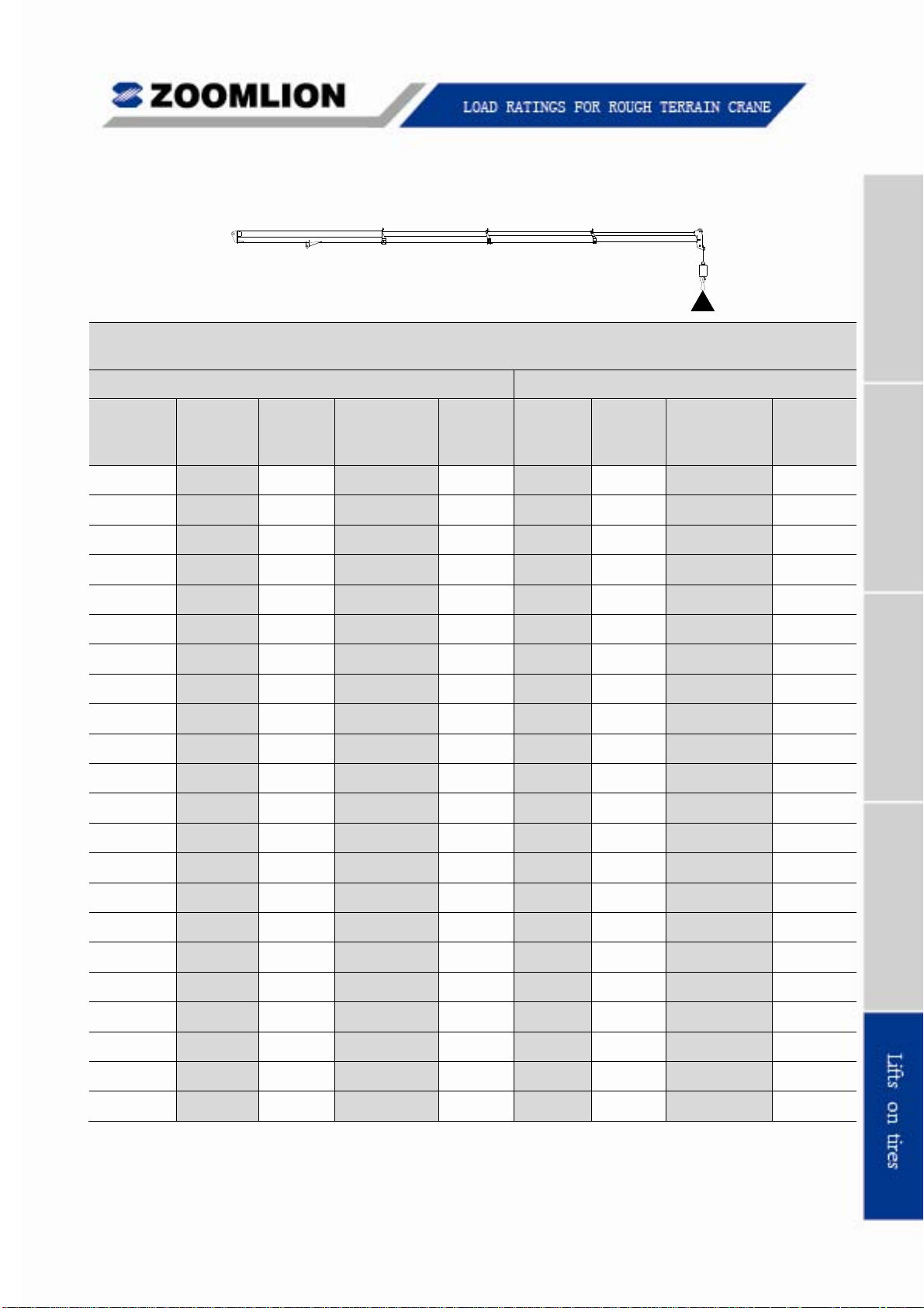
5.1 MAIN BOOM RATED LOADS
Rated loads on tires
(Rated load unit: kg)
Boom Length of 10800 mm Boom Length of 15440 mm
Working
Radius
(mm)
Boom
Angle
(º)
360
(º)
Stationary
over Front
Pick
&
Carry
Boom
Angle
(º)
360
(º)
Stationary
over Front
Pick
& Carry
3000 66.82 17360 27250 20200 74.15 17900 27520 20600
3500 63.79 14830 24200 17830 72.18 15360 24650 18250
4000 60.67 12800 21710 15890 70.18 13300 22150 16350
4500 57.43 11150 19580 14260 68.16 11700 20040 14710
5000 54.05 9790 17780 12850 66.10 10290 18210 13330
5500 50.48 8670 16220 11700 64.00 9140 16690 12120
6000 46.69 7670 14920 10640 61.86 8160 15350 11070
6500 42.61 6850 13560 9690 59.67 7320 14160 10140
7000 38.11 6110 11890 8920 57.42 6600 12460 9330
7500 33.01 5320 10520 8200 55.11 5850 11060 8630
8000 26.90 4620 9380 7510 52.72 5130 9900 7970
8500 18.51 4020 8420 6960 50.24 4500 8920 7390
9000 0 3720 7940 6690 47.66 3960 8080 6850
9500 44.96 3490 7350 6330
10000 42.11 3070 6710 5690
10500 39.07 2700 6160 5130
11000 35.79 2370 5660 4640
11500 32.19 2080 5220 4200
12000 28.13 1810 4830 3810
12500 23.33 1570 4470 3460
13000 17.05 1360 4160 3150
13500 0 1240 3940 2940
RT55 Rough Terrain Crane 05-1
Page 47
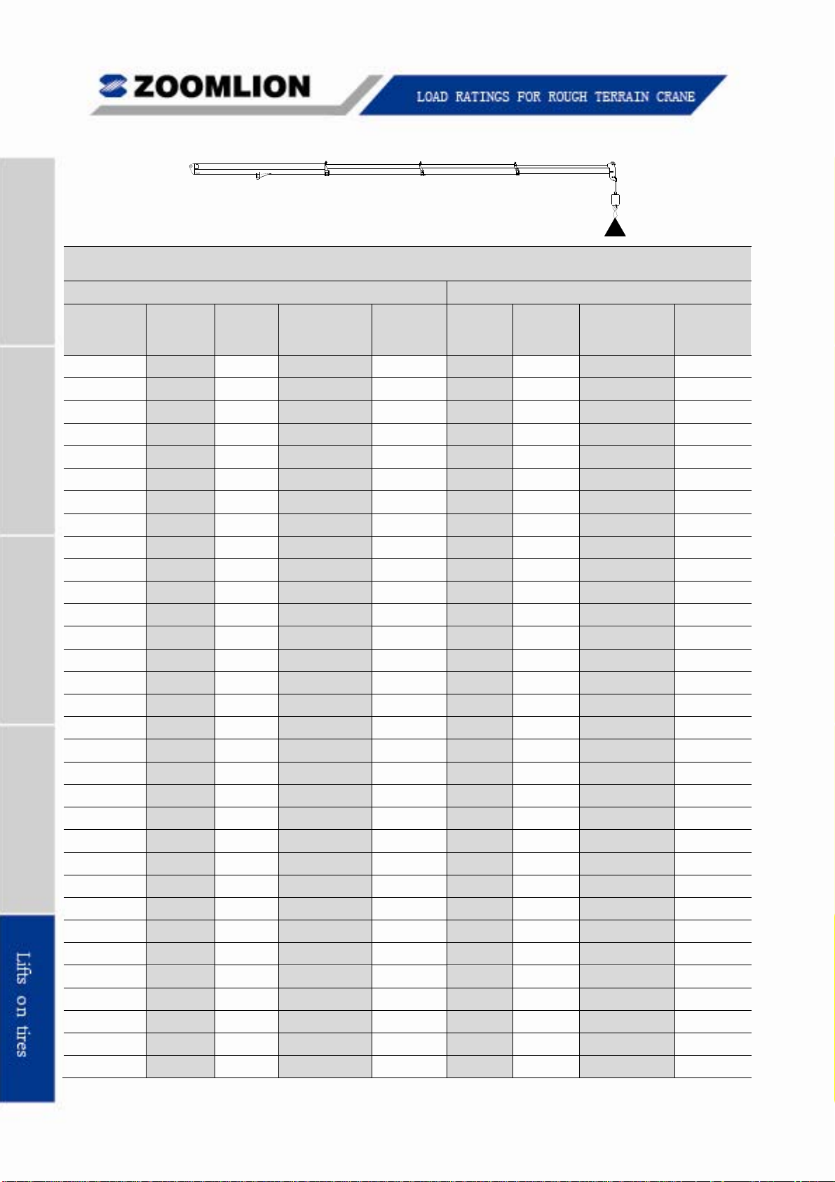
Rated loads on tires
(Rated load unit: kg)
Boom Length of 20080 mm Boom Length of 24720 mm
Working
Radius
(mm)
3000 77.91
3500 76.44
4000 74.95
4500 73.45 11970 20280 14950
5000 71.93 10630 18500 13570
5500 70.41 9460 16950 12370
6000 68.86 8460 15580 11350 73.02 8750 15790 11560
6500 67.30 7610 14420 10390 71.79 7890 14610 10640
7000 65.71 6880 12800 9620 70.55 7150 13070 9800
7500 64.11 6170 11390 8860 69.30 6420 11650 9080
8000 62.48 5430 10210 8230 68.04 5680 10460 8440
8500 60.82 4800 9220 7640 66.77 5040 9460 7840
9000 59.13 4250 8370 7090 65.48 4490 8600 7330
9500 57.41 3770 7630 6600 64.18 4000 7860 6830
10000 55.66 3350 6980 5960 62.86 3570 7210 6180
10500 53.86 2970 6420 5390 61.53 3190 6630 5610
11000 52.01 2630 5910 4890 60.18 2840 6120 5100
11500 50.12 2320 5460 4440 58.81 2530 5660 4640
12000 48.16 2050 5060 4030 57.41 2250 5250 4230
12500 46.14 1800 4690 3670 56.00 2000 4880 3860
13000 44.04 1570 4360 3340 54.55 1760 4550 3530
13500 41.85 1360 4060 3040 53.08 1550 4240 3220
14000 39.55 1170 3780 2760 51.58 1350 3960 2940
14500 37.13 3530 2510 50.04 1170 3700 2680
15000 34.55 3300 2280 48.47 3460 2440
15500 31.77 3080 2060 46.85 3240 2220
16000 28.72 2880 1870 45.19 3040 2020
16500 25.31 2700 1690 43.47 2850 1830
17000 21.33 2540 1520 41.70 2670 1650
17500 16.31 2380 1370 39.85 2500 1490
18000 7.94 2250 1250 37.93 2350 1330
18500 0 2250 1250 35.91 2210 1190
Boom
Angle
(º)
360
(º)
Stationary
over Front
Pick
& Carry
Boom
Angle
(º)
360
(º)
Stationary
over Front
Pick
& Carry
05-2 RT55 Rough Terrain Crane
Page 48

Rated loads on tires
(Rated load unit: lb)
Boom Length of 35 ft Boom Length of 51 ft
Working
Radius
(ft)
10 66.54 37620 59290 43890 73.97 38720 60170 44770
12 62.82 31160 51470 37880 71.56 32270 52360 38720
15 56.96 24080 42530 30930 67.87 25260 43510 31900
20 45.94 16540 32280 23000 61.45 17610 33220 23920
Boom
Angle
(º)
360
(º)
Stationary
over
Front
Pick
& Carry
Boom
Angle
(º)
360
(º)
Stationary
over
Front
Pick
& Carry
25 31.66 11320 22500 17620 54.54 12470 23680 18570
30 0 8200 17480 14720 46.90 8410 17290 14820
35 38.00 5700 13170 10920
40 26.40 3790 10310 8080
45 0 2720 8680 6470
Boom Length of 66 ft Boom Length of 81 ft
Working
Radius
(ft)
10
12
15 73.24 25950 44020 32410
20 68.57 18270 33820 24520 72.78 18790 34270 24980
25 63.72 13160 24390 19160 69.00 13720 24960 19630
30 58.65 9040 17920 15330 65.11 9560 18430 15740
35 53.25 6270 13730 11480 61.08 6750 14200 11950
Boom
Angle
(º)
360
(º)
Stationary
over
Front
Pick
& Carry
Working
Radius
(ft)
Boom
Angle
(º)
360
(º)
Stationary
over
Front
40 47.40 4290 10810 8560 56.87 4740 11240 9000
45 40.88 2810 8660 6420 52.44 3220 9060 6810
50 33.25 1670 7030 4790 47.70 2040 7380 5140
55 23.30 5750 3520 42.54 1110 6060 3820
60 4970 2760 36.78 4990 2760
65 30.02 4120 1890
RT55 Rough Terrain Crane 05-3
Page 49

SET-UP
1. Crane load ratings are based on the crane being leveled
and standing on a firm and uniform supporting surface.
2. Crane load ratings on tires depend on appropriate
CRANE WORKING POSITIONS
WITHOUT OUTRIGGERS
360
±3
OVER FRONT
C
BOOM
L
WITH OUTRIGGERS
360
inflation pressure and tire condition. Caution must be
exercised when increasing air pressures in tires.
CENTER OF
ROTATION
Consult Operator’s Manual for precautions.
THESE LINES DETERMINE THE LIMITS OF
3. Use of jib is not permitted for pick-and-carry operations.
WORKING POSITIONS WHITCH CORRESPOND TO
THOSE SHOWN ON THE CRANE CAPACITY CHART.
SET-UP
1. For pick-and-carry operations, boom must be centered over the front of the crane with
swing and brake lock engaged. Use minimum boom point height and keep load close to
ground surface. Travel must be on smooth level surface.
2. The load should be restrained from swinging. No on tire operation with jib erected.
OPERATION
1. CRANE LOAD RATINGS MUST NOT BE EXCEEDED. NO ATTEMPT TO TIP THE
CRANE TO DETERMINE ALLOWABLE LOADS.
2. When radius is between listed values, the smaller of the two listed load ratings shall be
used;
C
L
BOOM
3. Do not operate at longer radii than those listed on the applicable Lift Chart as tipping can
occur without a load on the hook.
4. All telescopic sections must be extended synchronously.
5. Without outriggers, never maneuver the boom beyond listed load radii for applicable tires
used to ensure stability.
6. Creep speed is crane movement of less than 61 m (200ft) in 30-minutes period and not
exceeding 1.6 KM/H (1MPH).
05-4 RT55 Rough Terrain Crane
Page 50
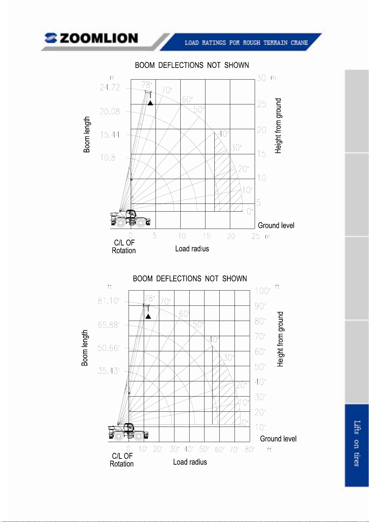
Lift Heigth on Tires
RT55 Rough Terrain Crane 05-5
 Loading...