

Page 1

OPERATOR'S MANUAL FOR
RT35 ROUGH TERRAIN CRANE
Address:Quantang Indust=rial Park, 2nd Yuanda Road,
Changsha Economic and Technological Development
Zone, Hunan Province, China
Postcode: 410131
Website: www.zoomlion.com
Page 2

RT35 ROUGH TERRAIN CRANE
OPERATOR’S
MANUAL
Edition 1
Dec.2013
Page 3

Page 4

Zoomlion Cranes appreciates your selection of the ZOOMLION Rough Terrain Crane
for your application.
No one should operate the crane unless they read and understand the information in
this manual.
When you follow the instructions in this manual, your crane can operate at MAXIMUM
EFFICIENCY.
The operator must keep this manual in the cab of the crane.
If there is anything in the manual that you do not understand, speak with us. We
(Zoomlion Cranes) are NOT responsible for damages from an operator who does not
obey the instructions in the OPERATOR’S MANUAL.
The OPERA T OR’S MANUAL is an important part of the crane. If the crane becomes the
property of a different person, make sure that the manual stays in the cab of the crane.
THANK YOU!
Mobile Crane Branch Company of ZOOMLION Heavy Industry Science and Technology
Co., Ltd.
Copyright
Under the copyright laws, this manual may not be copied, photocopied, reproduced,
translated, or reduced to any electronic medium or machine readable form, in whole or
part, without the prior written consent of Zoomlion Heavy Industry Science and
Technology Co., Ltd.
Copyright © 20XX, Zoomlion Heavy Industry Science and Technology Co., Ltd.
All rights reserved.
RT35 Rough Terrain Crane I
Page 5
Attention
Note
Caution
Warning
Danger
Important
Hazard Indicators
DANGER, WARNING, CAUTION, ATTENTION, NOTE, and IMPORTANT labels are on
signs and decals, and as you read this manual to show important instructions. In this
manual, DANGER, WARNING, and CAUTION labels are before the paragraph or item to
which they apply. ATTENTION, NOTE, and IMPORTANT follow the paragraph or item
they apply to. The markers are as follows:
Refers to a dangerous situation which, if you do not prevent, will cause death or
injury.
Refers to a possible dangerous situation which, if you do not prevent, could cause
death or injury.
Refers to a possible dangerous situation which, if you do not prevent, may cause
light or moderate injury.
Refers to a situation which, if you do not prevent, may cause property or equipment
damage.
Refers to a tip or hint in the operation instructions.
Emphasizes the importance of the data in this manual.
This symbol shows a step or procedure that is not approved and can cause a dangerous
situation.
II RT35 Rough Terrain Crane
Page 6

To owners, users and o perators
............................................................................................ I
Safety
1 Foreword
2 Nomenclature
3 Introduction
4 Safety
5 Operating conditions and points for attentio n
....................................................................................................................................... II
......................................................................................................................... 1-1
................................................................................................................. 2-1
.................................................................................................................... 3-1
.............................................................................................................................. 4-1
........................................................... 5-1
5.1 Operating conditions .............................................................................................. 5-1
5.2 Pre-departure checks (to job-site) .......................................................................... 5-3
6 Controls and instruments
7 Operating instructions
............................................................................................. 6-1
.................................................................................................. 7-1
7.1 Safety equipment .................................................................................................... 7-1
7.2 Starting the engine ................................................................................................. 7-2
7.3 After the engine starts ............................................................................................ 7-2
7.4 Cold weather starting ............................................................................................. 7-3
7.5 Move and park the crane ....................................................................................... 7-3
7.6 Economical driving ................................................................................................. 7-4
7.7 Steering operation .................................................................................................. 7-5
7.8 Braking operation ................................................................................................... 7-6
7.9 Transmission operation.......................................................................................... 7-7
7.10 Towing .................................................................................................................. 7-8
7.11 Outrigger operation .............................................................................................. 7-9
7.12 Hoist operation ................................................................................................... 7-12
7.13 Main boom extend / retract operation ................................................................ 7-22
7.14 Boom derrick operation ...................................................................................... 7-30
7.15 Swing operation ................................................................................................. 7-32
7.16 Multifunctioning .................................................................................................. 7-35
7.17 Jib operation ...................................................................................................... 7-42
7.18 Rooster sheave .................................................................................................. 7-50
7.19 Vehicular operation ............................................................................................ 7-53
7.20 “On tires” lifts ...................................................................................................... 7-57
7.21 Unusual operating conditions ............................................................................ 7-58
8 Transportation and storage
........................................................................................ 8-1
8.1 Transportation ......................................................................................................... 8-1
8.2 Storage .................................................................................................................... 8-3
RT35 Rough Terrain Crane III
Page 7

9 Specifications
................................................................................................................ 9-1
9.1 Conversion tables ................................................................................................... 9-1
9.2 Average weight of materials ................................................................................... 9-3
9.3 Torque ratings ......................................................................................................... 9-5
9.4 Technical specifications .......................................................................................... 9-6
IV RT35 Rough Terrain Crane
Page 8

Page 9

Page 10

The owner of this crane must know federal, state and local rules. When your
equipment is in operation, the area must be safe for employees and non-employees.
Do not cause damage to other equipment or local structures while you operate this
crane. The rules change by location and this manual does not give that data.
ZOOMLION makes manuals for differ ent construction and industrial equipment. It is
policy to include applicable national consensus, industry standards and safety data
with the manuals. Use these data to give applicable training to personnel who are to
operate, do the maintenance and supervise the equipment correctly and safely.
We make equipment for heavy-duty labor. Do the periodic inspections regularly
because the equipment wears. This prevents accidents, decreases downtime and
helps equipment work satisfactorily. The goal of these inspections is to find worn,
cracked, damaged parts and loose or missing fasteners before they cause a problem.
Correct training and inspection procedures are necessary to prevent injury to persons,
property damage and high maintenance costs.
Read and understand the data that comes with this crane. Help is available from the
distributors of your ZOOMLION crane and from the ZOOMLION Mobile Crane Branch
Company.
This manual contains the instructions and data on the operation, maintenance,
lubrication, and adjustments of the Rough Terrain Crane. Do not operate the crane
before you understand the data in this manual.
RT35 Rough Terrain Crane 01 - 1
Page 11

Page 12
Page 13

Page 14
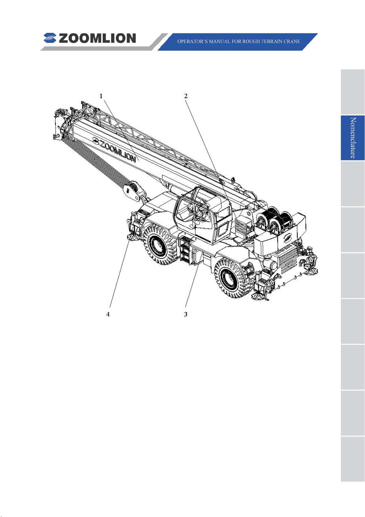
To help you understand the contents of this manual, refer to the figure below. Each
numbered term can represent several components of the same main par t .
LEGEND
1. BOOM SYSTEM = Main boom assy., jib assy., telescoping mechanism, hook block ,
auxiliary hook, hoist rope.
2. SWING SYSTEM = Superstructure, counterweight, main and auxiliary winches,
swing bearing, swing redu cer , derricking cylinder, cab, air
conditioner and cab heater.
3. CHASSIS = Power system, dr ive system, steering system, air intake system,
exhaust system, cooling system, fuel supply system, chassis
frame assy. and vehicle b ody system.
4. OUTRIGGERS = Outrigger beams, outrigger jac ks, cylinders and outrigger floats.
RT35 Rough Terrain Crane 02 - 1
Page 15

Page 16

Page 17

Page 18
Inspection
Code
Function
Adjusting
Condition
Maintenance
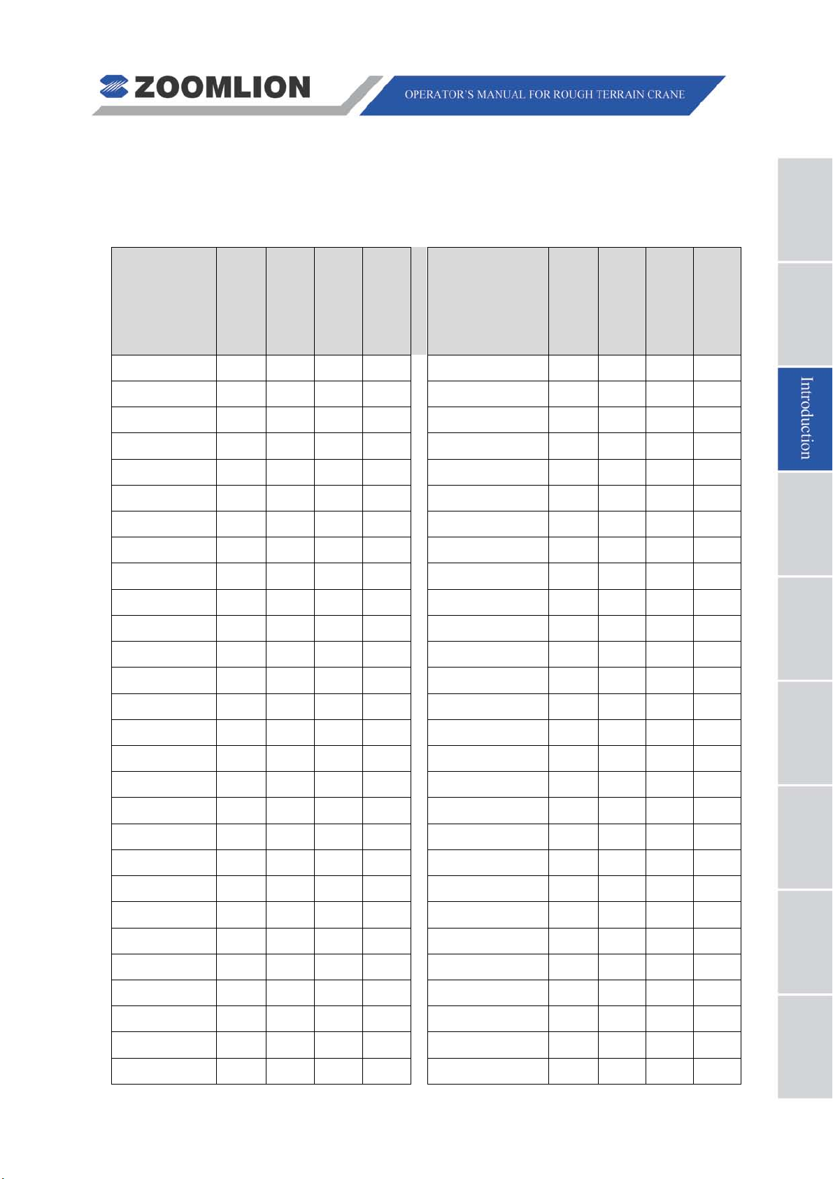
CRANE PERIODIC INSPECTION CHECKLIST
This inspection checklist provides supplementary data to facilitate the correct operation
and maintenance of the crane.
Component
Inspected
Interval
Function
Adjusting
Condition
Maintenance
condition
Component
Inspected
Condition
RT35 Rough Terrain Crane 03 - 1
Page 19

Item Adjusting Condition
Date
MAINTENANCE LOG
03 - 2 RT35 Rough T errain Crane
Page 20

About This Manual
General
The data (data, speci fica t i ons, illustrations) in this manual is for cranes in production at the
time of this manuals publication. We reserve the right to make changes to this manual at
any time, without obligation.
This manual contains the instructions to move and operate the RT75 Crane in the field.
Follow the operation and maintenance procedures to make sure that your machine
operates at MAXIMUM EFFICIENCY. Use the CRANE PERIODIC INSPECTION
CHECKLIST. Keep a maintenance log to monitor all maintenance w ork on the machine.
An example of a Maintenance Log and Crane Periodic Inspection Checklist is at the
beginning of this section.
Again, we appreciate your selection of our crane. User safety is most important. To
complete on-site tasks safely, operators must be responsible. Obey the instructions that
follow:
Comply – with Occupat ional Sa fety and H ealth Ad ministr ation (OS HA), Fed eral, State,
and Local Regulations.
Read, Understand, and Follow – the instructions in this and other manuals and
documents that come with t he cr ane.
Use Good, Safe Work Practi ces – in a common sense way.
Only have trained operators – directed by informed and knowledgeable job-site
supervisors.
Do not use this crane – before the portable fire extinguisher, installed in the cab,
agrees with local fire protection rules.
Note
OSHA prohibits the alteration or modification of this crane without written
manufacturer’s approv al. Use o nly factory approv ed parts t o serv ice or repair
the crane.
If you make modifications/additions "which affect the safe operation of the
equipment" to the crane before you use it, the crane owner must make sure
that the modifications/ad di t ions agree with OSHA 1926:1412.
RT35 Rough Terrain Crane 03 - 3
Page 21

Speak with us if special data is necessary for the maintenance or operation of your RT75
Crane. Send your machine model and a serial number to make sure that you receive the
correct data.
If there is anything in this manual that is not clear or which you think is necessary, write to
the address that follows:
Rough Terrain Crane R & D Institute
Zoomlion Mobile Crane Branch Company
nd
Quantang Indus t r ial Park, 2
Yuanda Road,
Economic and T e chnological Developm ent Zone,
Changsha, Hunan Province, China, 410131
You can also speak to us by telephone at 0086-84671987 (international), 0731-84671987
(domestic).
03 - 4 RT35 Rough T errain Crane
Page 22

Page 23

Page 24

Caution
Warning
Danger
4.1 HAZARD INDICATORS
DANGER, WARNING, CAUTION , ATTENTION, NOTE, and IMPORTANT labels are on
signs and decals, and as you read this manual to show important instructions. In this
manual, DANGER, WARNING, and CAUTION labels are before the paragraph or item to
which they apply. ATT ENTIO N, NOTE, and IMPO RTAN T follow the paragr aph or ite m they
apply to. The markers are as fo ll ow s:
Refers to a dange r ous situation which, i f you do not prevent, will cause
death or injury.
Refers to a possible dangerous situation which, if you do not
prevent, could cause death or injury.
Refers to a possible dangerous situation which, if you do not
prevent, may cause light or moderate injury.
Attention
Refers to a situation which, if you do not prevent, may cause property or
equipment damage.
Note
Refers to a tip or hint in the operation instructions.
Important
Emphasizes the importance of the data in this manual.
This symbol shows a step or procedure that is not approved and can
cause a dangerous situation.
RT35 Rough Terrain Crane 04 - 1
Page 25
Caution
Warning
Danger
4.2 SAFETY SY MB O L
The safety symbol, used on the Danger, Warning, and Caution labels, tells personnel
of possible death, injury, or property damage. Obey all safety data that follows this
symbol to prevent dangerous conditions.
4.3 Hazard classification
Hazard classification is a system to show different classes of possible injury levels. A
safety symbol and a signa l w or d show how dangerous the level of possible inj ur y can be.
A signal word without a safety symbol refers to property damage, protection devices, or
important data. You will find this system used in this manual and on signs on the crane to
help find and prevent dangerous situations.
4.4 SAFETY
This section contains the safety rules that you must follow. You must read and understand
the Operator’s Manual. I t co nt ai ns the instructions for the specified machine.
All personnel must be safe at t he work location.
Attention
A. Moving personnel
Only use a crane to lift personnel when it is the less dangerous mode to move them to
areas that are hard to access.
B. Operator’s responsibilities
Read and understand the Operator's Manual.
The operator must alway s t hink about the safety of all personnel in the area.
Only personnel who show that they can safely control a RT75 crane can operate the
crane.
Comply with the require m ent s, t hat apply, as follows:
Occupational Safety and Hea lt h Administration (OSHA) standards
American National Standards Institute (ANSI)
China National Standar ds G B/ T3811.
Make sure that all the me chanical functions of the crane can operate.
04 - 2 RT35 Rough Terrain Crane
Page 26

Make sure that the system operating gauges and indicators, and warning signals
function.
Keep all the glazed surfaces, instruments, windows, and lights clea n.
Remove all oil, grease, m ud, ice, and snow from walkway surfaces.
Read and understand all Dec als and Warnings.
Keep all tools and other necessary items in the toolbox.
Do not lift a load without a Load Ratings in the cab.
Read and understand the Load Ratings.
Make sure that the load to lift is le ss than the capacity of the crane.
Be in good physical condition and free from effects of alcohol, drugs and medications.
Be sure to not decrease vision, hearing, or reaction time.
Keep personnel, equipment and material that are not necessary for your task at the
job-site out of the area.
The operator must know the hand signals.
When the view of the operator is blocked or if the task is in a dangerous area, use
signal personnel to give di r ect ions.
If a signal person is necessary, the operator must obey only the signals from the
approved signal person. You must obey the STOP signal from all personnel in the
area.
Keep a fully charged fire extinguisher and first aid kit in the cab at all times. The
operator must know how to use the fire extinguisher and how to apply the items in the
first aid kit.
Look for the movement of other equipment, trucks, and personnel at the job-site.
Personnel must stay off the cr ane platform while the crane is in operation.
All personnel must be in a safe area before you move the hook, boom, load, or
outriggers.
Stop and start the move ment of the loa d smoot hly and move at a spe ed that keeps t he
load in your control.
Keep a minimum of three full wraps of wire rope on the drum.
Use the tag lines to keep the load in c ont r ol.
Keep the load near the ground.
Use the shortest boom possible.
If a load is off the ground or the crane is on, you must stay in the cab.
Always use outriggers as the Load Ratings and Operator’s M anual tells.
RT35 Rough Terrain Crane 04 - 3
Page 27

C. Signal personnel responsibilities
Use and understand all standard hand signals.
Help the operator to operate safely and satisfactorily. Keep safe all personnel and
property.
Understand the work you must do.
Stay where you can see the full operation and where personnel can see you.
D. Res ponsibilities of all crew members
Correct the conditions an d procedures that are not safe.
Obey WARNING signs.
Do your work safely and do not make dangerous conditions.
Know and understa nd correct procedures for crane erection and r i gging.
Tell the operator and the signal person of dangerous conditions (power lines/cables,
work surface that is not stable etc.).
E. Management responsib ilities
The operator must be competent, in good physical condition and have applicable
licenses.
The operator, signal person, and riggers must receive training in correct crane
operation.
The operator and the signal person must know all standard hand sig nals.
Have a supervisor at the job-site to be responsible for safety.
Give crew members the safety instructions and tell them to report conditions that are
not safe to the supervisors.
Supply the operator with accur at e data on the load that they have to lift .
Make sure that all personnel know applicable OSHA and ANSI B30.5 re quirements
and the instructions in manuals.
F. Planning the job
Understand the work that you must do.
Think of all possible dangerous conditions/risks at the job-site.
Know the type of personn el that is necessary.
Give the tasks to perso nnel.
Know the weight of the load t hat you must lift.
Find the lift-radius, boom angle, and the rated lift limit s of the crane.
Tell the signal person how to communicate with the operator.
04 - 4 RT35 Rough Terrain Crane
Page 28

Use equipment which doe s t he w or k sa f ely.
Make a decision on how to saf ely move equipment to the job-site.
Find gas lines, power line s and st r uct ur es.
Make sure that the work surfac e ca n hold the crane and load.
Find out how to rig the load.
If necessary, make the special safety pr ecautions.
Know the weather conditions.
Keep equipment that is not necessa r y away from the job-site.
Set the crane to use the shortest possible boom and radius.
G. Operator safety check
Safety related items must be in position.
Look at the crane logboo k for m ai nt enance and inspection records.
Make sure to complete necessa r y repairs.
Examine the wire rope for damage (kinks, broken wires etc.).
Make sure that all field mo difications are approved.
Do an inspection for air an d hydraulic oil leaks.
Examine the control posit i ons before you start the engine.
After you start the engine, examine all the instruments and indicators for the correct
values.
Do a test on the controls.
Check brakes.
Lift and hold a load 2 inch (50 mm) off of the wor k sur face to ex a mine t he load brakes.
H. Operator aids check
Anti-Two Block devices
Boom angle indicator
Backup alarms
Swing lockout device
Rated capacity indicator (RCI)
rd
3
wrap indicator.
I. Operation overload prev ention
Know the weight of the load.
Decrease radius at the start of the lift to let the load radius incr ease during lift.
RT35 Rough Terrain Crane 04 - 5
Page 29

Know the weight of the hook and rigging.
Know the boom length, jib lengt h, and the area where you have to move the lo ad.
Use next lower rated capacit y w hen wor king at the boom len gth or r adius bet w een the
figures on the rated lifting capacity chart.
Do not lift a load until y ou know if the load is less than the capacity lim it of the crane.
Only operate with the recomm ended counterweights. It is dangerous i f you do not use
the approved charts t o calculate the decrease or increase in cou nt er w eight.
Do not lift the load if winds are dangerous. If necessary, low er t he boom.
See the Load Ratings for poss ib le restrict ions.
Avoid side loading.
Do not let the load or other objects hit the boom.
Release the load slowly, be sure the boom does not tighten against back stops.
Put the boom point directl y above the load.
Be sure that the load hangs free ly.
J. Operation setup
Be sure the load-bearing sur fa ce can hold the weight of the crane and load.
Make crane level, check frequently , and r e-level them when necessary.
Assemble barricades to keep personnel out of the load move radius.
K. Power line safety
Find power lines in the area before you start a task. Follow national and local
regulations and ANSI B30.5 when you operate ar ound power lines.
Do not remove the material fro m below power lines if the boo m or crane can touch the
lines.
Do not let the crane or load touch electrical lines. Do not go near the minimum
permitted clearance for op er at ion of a crane near electrical lines.
If you touch the electrical lines, stay on the crane unt il the boom moves off the lines or
until the power line current is off.
Keep all personnel off the crane if it touches power lines. If you must move from the
crane, JUMP, DO NOT STEP OFF. Jump with feet together.
Use a signal person when you operate around power lines
L. Slip and fall prevention
Make sure that you stop the crane before you move on and off the equipment. Do not
jump.
Do not use the controls and the st eer in g-wheel as hand holds.
04 - 6 RT35 Rough Terrain Crane
Page 30

Keep the equipment clean and dr y.
Replace all broken ladders.
Keep the non-slip surfaces in good condit ion.
Wear a safety harness when you climb the counterweight and attach the harness in
the necessary points. Do not walk on the boom!
M. Travel
Be careful when you move cranes on or off the job-site.
Look for personnel, power lines, low or narrow clearance, bridge or road loa d limi ts,
steep hills, or rough terrain.
Correctly stow the boo m b efore you move the crane.
Inflate the tires to the specified pr essure.
Move slowly and prevent sudden movement.
Wear seat belt correctly when you move the crane.
Make sure that the trav el surface can hold the weight of the crane and load.
Always use the park bra ke when you park the crane.
N. Safety sign maintenance
During the daily inspection, make sure that the decals show and are in good condition.
Replace all missing or damaged safety signs. The safety of the operator is always
important.
Use a weak soap and water to clean the safety signs. Do not use solvent-based cleaners.
Solvents can cause da ma ge t o t he saf ety sign material.
The graphics, on the pages that follow, give an example of each safety decal and its
location.
RT35 Rough Terrain Crane 04 - 7
Page 31

Left-hand side
Right-hand side
Figure 04 – 1 Overview of the Safety Signs on the Machine
04 - 8 RT35 Rough Terrain Crane
Page 32

1
Figure 04 – 2 Danger – Crush Hazard
2
Figure 04 – 3 Danger – Electrocution Hazard
RT35 Rough Terrain Crane 04 - 9
Page 33

3
Figure 04 – 4 Hand Signals for Crane Operation
04 - 10 RT35 Rough T errain Crane
Page 34

4
Figure 04 – 5 Danger – Explosion / Burn Hazard
5
Figure 04 – 6 Danger – Crush Hazard
RT35 Rough Terrain Crane 04 - 11
Page 35

6
Figure 04 – 7 Danger – Burn Hazard
7
Figure 04 – 8 Prohibited – No Thoroughfare
8
Figure 04 – 9 Prohibited - No Access / Only Authorize d P er sonnel
9
Figure 04 – 10 CAUTION - Risk of Falling
04 - 12 RT35 Rough T errain Crane
Page 36

10
Figure 04 – 11 CAUTION - Swinging Load
11
Figure 04 – 12 No Swing over the Rear with -3°
12
Figure 04 – 13 Entanglement Hazard
Keep all open flames and
sparks away.
13
Figure 04 – 14 Keep All Open Flames and Sparks A way – RH Only
RT35 Rough Terrain Crane 04 - 13
Page 37

14
Figure 04 – 15 Be Careful in the Working Radius – RH Only
15
Figure 04 – 16 No Walk – RH Only
04 - 14 RT35 Rough T errain Crane
Page 38

Page 39

Page 40

Warning
5.1 OPERA TING CONDITIONS
A. Always use the correct light diesel fuel and engine oil. Make your selection on the
lowest ambient temper atu re w here y ou are t o do t he work. Refer t o the t abl e b elow for
more data on diesel and engine oil. Obey the Engine Manual if the data in thi s table is
incorrect.
Engine Emission Oil Brand Specification
According to guidelines
per US EPA Tier 3
Emission Standards
According to guidelines
per EURO stage III A
Emission Standards.
Sulfur content < 15 PPM,
according to US EPA2007
regulations
Sulfur content < 15 PPM,
according to EN 590
regulations.
CH – 4 stage, API classification
CH – 4 stage, API classification
The fuel sulfur content i n the fu el must be l ess t han 15 P PM to ob ey US EPA
Tier 3 Emission Standards.
The fuel sulfur content must be less than 15 PPM to obey EU RO stage III A
Emission Sta n dards.
Do not use fuel that is mixed with a lubricant or unqualified additives.
B. All mechanical components are in a break-in state during initial crane operation (less
than 100 operating hours). You must follow the below instructions during this time
period:
The working load and working speed must not be to o high.
The ma xi m um lift capacity should not be larger than 80% of the rate one.
Do not o perate the crane at a speed that is more than t he maximum limits.
C. Make sure that you do all of the work on level ground that is hard. The ground must
hold more than the load bearing capacity (permissible ground pressure ≥ 507.5 PSI
(3.5 MPa). Use material (such as wooden timbers) below the outrigger floats if the
work area is soft or not flat.
D. Before you operate the crane that is supported on outriggers, all wheels must not
touch the ground. Before "On tires lifts", make sure that you align the crane wheels to
the middle.
E. Do not operate the crane if the t emperat ure at the jo b-sit e is mor e than -4° F to 104° F
(-20° C to +40° C).
F. If wind speed is greater than the permissible value of 45 ft/s (13.8 m/s), while the
crane is in operation, do the tasks that follow:
Stop the work (safely lower the load).
RT35 Rough Terrain Crane 05 - 1
Page 41

Beaufort
scale
Wind direction shown by smoke
drift but not by wind vanes
Leaves and small twigs in
light flag
Large branches in motion; dif fic ult
in telegraph wires
Whole trees in motion, difficult to
walk against the wind
Breaks twigs off trees, impedes
progress
Slight structural damage (roof
blown off)
Trees uprooted, considerable
damage occurs
Retract the boom.
Correctly stow the boom.
To make an estimate of the wind speed, use the table that follows:
Wind force Wind speed
Effect of the wind on the land
Description ft-in/s m/s
0 Calm
1 Light air
2
3
4
5
6
Light
breeze
Gentle
breeze
Moderate
breeze
Fresh
breeze
Strong
wind
7 Near gale
0 - 8″ 0 - 0.2 No wind, smoke rises verti cally
1′-4″ - 4′-7″ 0.4 - 1.4
5′-3″ - 9′-10″ 1.6 - 3
11′-2″ - 17′-5″ 3.4 - 5.3
Wind felt on face, leaves rustle,
vanes moved by wind
constant motion, wi nd extends
18′-1″ - 25′-7″ 5.5 - 7.8 Small branches move
26′-3″ - 34′-9″ 8 - 10.6 Small trees in leaf begin to sway
35′-5″ - 45′-0″ 10.8 - 13.7
to use umbrellas, whistlin g hear d
45′-7″ - 55′-9″ 13.9 - 17
8 Gale
9 Strong gale
10 Storm
G. Do not operate the crane unl ess t he conditions are safe.
05 - 2 RT35 Rough Terrain Crane
56′-5″ - 67′-7″ 17.2 - 20.6
68′-3″ - 80′-5″ 20.8 - 24.5
81′-0″ - 92′-10″ 24.7 - 28.3
tiles and chimney cover s, etc.
Page 42

Caution
5.2 PRE-DEPARTURE CHECKS (TO JOB-SITE)
A. VEHICLE CHECKS (PRIOR TO ENGINE START)
(1) Do a check of the level of coolant and add more if below the cold engine level.
(2) Do a check of the fuel level and make sure that y ou hav e more than is necessary
to complete the task.
(3) Make sure that the parts in the steering and brake systems are flexible, safe, and
reliable.
(4) Make sure that the parts that follow are tight:
B olts in universal joints for steering axles
Front and rear axles mounting bolts
Wheel bolts
Driv e shaft mou nting bolts
Engine and transmission mounting bolts.
(5) Examine all tires for the cor r ect pressure.
(6) Examine the items that follow for damage:
Condition of tires
Door locks
Doors
Windows
Crane control mechanisms.
(7) Examine the fittings of oil pip es, air pipes and water pipes for leakage.
(8) Examine the air pressure tank for condensation (drain the water as necessary).
(9) Examine the battery terminals for too much corrosion and make sure that the
power wires are tight.
(10) Examine the level of the battery elect r oly te (adjust as necessary).
(11) Examine the air filter indicator. If the indicator is red, clean or replace the filter
cartridge.
The air filter system must be clean prior to starting the engine.
(12) Examine the air filter assembly. Clean the contamination from the bottom of the
air filter.
(13) Turn the ignition switch to stage “I” and examine the functions of the items that
follow:
RT35 Rough Terrain Crane 05 - 3
Page 43

Caution
Caution
I nstrument panel
Switches
All lights
Tur n signals
Wipers
M iscellaneous displays.
(14) Adjust the mirrors for clear vision to the rear .
B. GENERAL CHECKS AT VEHICLE START UP
Before you start the vehicle on a steep slope or a muddy road, move the
transmission selection lever into “F1” positio n.
Do not turn the power supply OFF while the engine in ON. The instruments,
signals, and indicators do not operate. This causes a dangerous condition
because the ECU does n ot have power.
Examine the controls and instruments.
((11))
Examine the transmission oil pressure gauge.
((aa))
1 The transmission oil pressure must be between 240 PSI (1.7 MPa) – 310
PSI (2.1 MPa).
Examine the compressed air supply.
((bb))
Examine the engine coolant temperature gauge.
((cc))
1 After the engine has the time to warm-up, the pointer must point to the
green range (between 158° F (70° C) and 203° F (95° C)).
Make sure that the transmission gears sh i ft correctly .
((dd))
Make sure that the 360° superstructure loc k m oves correctly .
((ee))
Make sure that each indicator operates.
((22))
Make sure that the generator oper at es.
((33))
Make sure that the park bra ke is not ON.
((44))
Move the transmission selection lever to the “F1” position and slowly
((55))
the speed.
increase
05 - 4 RT35 Rough Terrain Crane
Page 44

Caution
Caution
Warning
Danger
C. MOVE THE CRANE TO THE JOB-SITE
Do not let the vehicle move forward when tr ansmission is in neutral.
Do not operate a vehicle if a warning indicator illuminates. Stop the vehicle and
have it repaired.
If a warning indicator illuminates, decr ease your speed immediately and stop at a
((11))
safe location for maintenance checks.
Do not skip a gear when you move thr ough t he gear cycle.
((22))
During driving, if there is any abnormal sound, smell, vibration or acceleration,
((33))
bring the vehicle to a standstill immediately and check. If the cause of problem is
unclear or if the problem cannot be rectified, send the vehicle to the specialized
repair factory.
Stop the vehicle if there are unusual c onditions with the items in the below list:
((44))
Steering
Braking
Sounds or smells
Vibrations
Sudden speed increase or decrease.
If you cannot find or correct t he pr oblem, send the vehicle for repair.
Monitor the indicators / gauges that follow:
((55))
Engine oil pressure low indicator
((aa))
Stop the engine if the engine oil pressure low indicator illuminates.
The engine oil pressure low indicator illuminates if the engine oil filter
screen is dirty. If this occurs, examine the engine oil pressure. If it is in the
correct pressure range, check and clean the engine oil fil t er scr een.
When the engine is running at the idle speed, the engine oil pressure is
about 55.1 PSI (0.38 MPa) .
The engine oil pressure low indicator illuminates w hen the oi l pressure is less
than 10 PSI (0.069 MPa). If this occurs, stop the engine.
Measure the oil level in the eng ine and ch eck for leaks. If the oil level is at the
correct level and there are no leaks, examine the lubricating system. S end it
RT35 Rough Terrain Crane 05 - 5
Page 45

Caution
Caution
Caution
to the servicing and repair personnel.
Engine coolant temper at ure gauge
((bb))
1 The coolant temperature must be between 158° F and 203° F (70°C and
95°C). Do not move the crane at high speed when the coolant
temperature is less than 158° F ( 70°C).
2 Do not operate the engine at high speeds without a load for extended
periods of time.
Do not move the crane at high speeds with a heavy load until the engine
coolant temperature is a minimum 158°F (70°C).
3 When the coolant temperature is in the yellow area, between 203°F and
212° F (95°C - 100°C), the engine is too hot. Park the crane. Operate the
engine at a RPM immediately above idle to help cool the engine. Or, as
you move, put the transmission in a lower gear range to decrease the
load on the engine.
Do not stop the e n gine i mm ediat ely when the engine cool a nt temperature is
above the maximum limit. If you stop the engine, the coolant temperature
increases suddenly and damage to the engine occurs. Operate the engine
at a RPM immediately above idl e t o help decrease the coolant temperature.
4 When the coolant temperature gauge points to the red area, between
212°F and 248°F (100°C - 120°C) continuously, it shows that the engine
is above limits. If you stop the engine, the coolant temperature increases
suddenly and damage t o the en gine occur s. Op erate the engine at a RPM
immediately above idle to hel p decrease the coolant temperature.
5 When the coolant temperature goes back to the green or yellow area, do
the items that follow:
Exam ine the engine area for leaks.
Examine the function of the thermostat.
Check the coolant level.
Check the fan belt for damage.
Make sure that the fan belt is not too loose.
Do not add a large quantity of cold water to t he engine if the engine coolant
temperature is above the maximum limit. This can kill or blind you and
cause damage to the engi ne.
Low engine coolant:
((cc))
05 - 6 RT35 Rough Terrain Crane
Page 46

Caution
Caution
Caution
Use soft water, e. g. tap water, for coolant. Do not use hard water (river
water).
1 Do not add a large quantity of cold water too quickly. When it is
necessary to add cold water, put the water in slowly. Follow the below
instructions to add coolant:
Put together water, antifreeze and/or anti-rust fluid in the correct
ratio.
Loosen the cap to the coolant tank with a wet rag to release the
pressure in the tank. After you release the pressure, continue to
remove the cap. The fluid released is hot and pressurized and can
cause burns or blindness. Always keep your fa ce away from the cap
on the coolant tank.
Add the water mix to the applicable coolant tank fill-line and then
install the cap.
Do not operate t he engine continuously at high speeds without a l oad.
Put the crane in a lower gear before you move up a slope to decrease the
((66))
load on the engine and drive-line.
Note
Make sure that the RPM of the engine is around maximum when you move up a
slope.
Do not bypass gears when you move to a lower gear.
Slow the crane down bef ore you change to a lower gear.
Do the items that follow before you go down a long hill slope:
((77))
Make sure that the brake system can stop the crane before you go onto the
slope.
Put t he t r ansmission in the ”F1” position before you go down the slope.
Know the below data while y ou steer the crane:
((88))
When you go into a corner, put the transmission in a lower gear and apply a
small quantity of pressure on the brakes.
The st eering wheel has a mechanical limit. Do not continue to turn the wheel
when at the limit. Do not keep the wheel at the limit for long periods of time.
If the engine stops becaus e the fuel t an k is e mpty , air can go into the fuel system.
((99))
RT35 Rough Terrain Crane 05 - 7
Page 47

Caution
When this occurs, you remov e t he air from the fuel lines.
When you move the crane between locations, only one person is approved to be
((1100))
in the cab.
D. CRANE MOVEMENT IN OFF-ROAD CONDITIONS
When the rear axle is in the mud (no t r act ion) or on rough terrain, follow these steps:
Put the transmission in the ”F1” position. This applies more torque to the drive
system.
Put the vehicle in the "4-wheel drive" mode.
Tow the vehicle or put rigid materials, e.g. pieces of wood or iron plates, below
the wheels.
E. PARK THE V EHICLE
Make sure that the hazard indicator illuminates when the vehicle is parked on the
road at night.
When you park the vehicle, follow the instructions below:
((11))
In bad weat her co ndit ion (r ain, snow, ice) or on a sl ope, make sur e t hat t here
is a lot of clearance in front and to the aft of the vehicle.
Put the park brake switch to the "P" position and put the chocks against the
wheels.
Put t he t r ansmission in the "neutral" position.
Before you stop the engine, do the items that follow:
((22))
Push the accelerator pedal 2 or 3 times to increase the engine RPM. This
makes the oil flow into each part of the engine.
Let the engine idle while you monitor the coolant temperature.
Stop the en gi ne, when the coolant temperature is in the corr ect r ange.
Put t he bat tery master switch to the OFF position.
F. EMERGENCY STOP ON THE ROADWAY
If the crane malfunctions on t he r oadw ay, do the items that follow:
Set the hazard lights to ON and put the safety t r iangles in po sit i on.
Set the park brake if you stop because of a drive train (drive shaft, axle) fa ilur e or
you make an emergency stop on a slope. Put the chocks on the wheels.
Exam ine t he vehicle to fi nd t he part that cause d the mal funct ion. Be careful o f the
road conditions while you mov e ar ound the vehicle.
If you ca nnot r epair the vehicle, tell the servicing and repair fac il ity.
05 - 8 RT35 Rough Terrain Crane
Page 48

G. PREPARE TH E CRANE FOR OPERATION
Examine the items that follow:
((11))
Engine oil for correct level and make sure that it is clean.
Coolant for correct level.
Fuel tank for correct level.
Hydraulic oil tank for correct level.
Start the engine and check for noises and vibrations that are not usual. If
((22))
necessary, engage the PTO.
H. WHEN THE CRANE IS IN OPERATION
Personnel must stay away from the area bel ow the boom.
((11))
Do not let personnel on the superstructure while you operate the cran e.
((22))
Personnel must stay away from the reach of the boom.
((33))
The crane, with extended outriggers, must be on the ground with a slope of less
((44))
than 1°.
Do not move a load above personnel.
((55))
Do not move personnel on the load or ot her equipment used to lift.
((66))
Do not use the crane for the tas ks that follow:
((77))
Lift a load that is above the capacity of the crane.
RT35 Rough Terrain Crane 05 - 9
Page 49

Pull a load at an angle.
Lift a load that is not in balance.
Do not try to lift a load that is buried or frozen on the ground.
((88))
Do not extend / retract the boom with a suspended load.
((99))
05 - 10 RT35 Rough T err ain Crane
Page 50

Keep no less than 3 wraps of wire rope on the drum.
((1100))
Whe n t he load is off the ground, do not adjust the winch mechanism brake.
((1111))
Whe n t he load is off the ground, the operator must stay in the cab.
((1122))
When the job-site is near live power lines, you must keep a safe distance. Make
((1133))
sure that the dangerous a r ea has a cover or is fenced off.
Whe n t he load is off the ground, move the load in a slow and smooth direction.
((1144))
Constantly monitor the system gauges and indicators, when the crane is in
((1155))
operation. If you find a malfunct i on, stop the operation.
A noise sounds when the load is at 90% of the capacity of the crane. W hen this
((1166))
occurs, be careful as you cont in ue t o lift.
If the crane was changed, do not operate the crane until approved personnel
((1177))
examine the changed p ar t .
RT35 Rough Terrain Crane 05 - 11
Page 51

Stop the operation or do not start to lift a load, if one of the items that follows
((1188))
occurs:
An overload or if the weight of the load is unknown.
The lo ad lift moves out of position, the rigging becomes too loose or the loa d
is out of balance.
The pr ot ective material between the edges of load and wire rope is missing.
The l ight level at the job-site goes below a safe wor k condition.
Equipment malfunction or damage to the crane that decreases the safe
operation of the crane.
05 - 12 RT35 Rough T err ain Crane
Page 52

Caution
Caution
Caution
I. TROUBLESHOOTING – ENGINE
If failures occur during crane operation, stop working immediately and remove the
safety hazards. At t he same ti m e, make the engine run at idle speed. After that, check
control instruments, e.g. transmission oil pressure gauge and engine coolant
temperature gauge, etc. for functional work.
It is a normal phenomenon that the engine oil pressure low indicator lights up
when starting the engine with the PTO engaged. The warning indicator will go
off after the oil pressure increases to the specified v al ue.
The illumination of the engine oil pressure low indicator indicates that the engine
((11))
oil pressure decreases abnormally. Bring the vehicle to a standstill immediately
and contact the manuf acturer or specialized repair f act or y.
Do not turn off the engine immediately when it is overheated. Otherwise, the
engine will be sintered caused by sudden raising coolant temperature. Check
for leaks when the engine is running for cooling. Stop the engine after the
coolant temperature decreases. At this time, reinspect engine coolant level and
check fan belt for dama ge s and loosening.
When the engine coolant temperature gauge points to the red area, cool down
((22))
the engine at the RPM a litt le higher than the idle RPM.
Points for at tention when adding c oolant:
Use pro per c oola nt.
When the coolant temperature is extremely high, hot water will spray.
Therefore, tighten or loosen the radiator cover using a piece of cloth.
Otherwise, there is a ris k of burn hazard.
RT35 Rough Terrain Crane 05 - 13
Page 53

Page 54

Page 55

Page 56

This part of the chapter is to show you the controls and instruments on the RT35 rough
terrain crane. This is only a small par t of the dat a that y ou must know before yo u can safely
operate the crane. Do not oper ate th e cr ane unti l you ar e tra ine d in a ll t he oth er sect ions o f
this manual.
6.1 UPPER CONTROLS AND INSTRUMENTS
1 2 3 4 5 6 7 8 9 10 11
12 13 14 15 16 17 18 19 20 21 22 23 24 25 26
Figure 06 – 1 Upper Controls and Instruments
RT35 Rough Terrain Crane 06 - 1
Page 57

LEGEND
1. High / Low Speed Select Switch for Main Winch
2. Steer ing Switch
3. Camera Display
4. High / Low Speed Select Switch for Aux. Winch
5. Air Conditioner Control Panel
6. A/C Fan Speed / M ast er Switch
7. Cab Heater Power Switch
8. Cab Cooler Power Switch
9. Monitor
10. Media player
11. Rated Capacity I ndicator (RCI) Display
12. Left Front Outrigger Switch
13. Left Rear Outrigger Sw itch
14. Emergency St op Butt on
15. Right Rear Outrigger Sw itch
16. Right Front Outrigger Switch
17. Work Lights Switch
18. Hazard Lights Switch
19. Cigarette Lighter
20. Ignition Switch
21. Outrigger Extend / Retract Master Switch
22. Swing Lock Switch
23. 2-Wheel / 4-Wheel Drive Swit ch
24. Hand / Foot Throttle Select Switch
25. Bypass Switch
26. Hand Throttle
06 - 2 RT35 Rough Terrain Crane
Page 58

1 2 3 4 5 6 7
8 9 10 11
Figure 06 – 2 Left dash
1. LEFT REAR OUTRIGGER SWITCH –
to be extended / retracted with
SWITCH (21)
(See Figure 06 – 1).
2. LEFT FRONT OUTRIGGER SWITCH –
beam) to be extended / retracted with
SWITCH (21)
(See Figure 06 – 1).
Used to select out r igg er cylinder (jack or beam)
OUTRIGGER EXTEND / RETRACT MASTER
Used to select outrigger cylinder (jack or
OUTRIGGER EXTEND / RETRACT MASTER
3. HIGH / LOW SPEED SELECT SWITCH FOR MAIN WINCH –
speed to OFF, LO W or HIG H.
4. RIGHT REAR OUTRIGGER SWITCH –
beam) to be extended / retracted with
SWITCH (21)
(See Figure 06 – 1).
5. RIGHT FRONT OUTRIGGER SWITCH –
beam) to be extended / retracted with
SWITCH (21)
(See Figure 06 – 1).
Used to select outrigger cylinder (jack or
OUTRIGGER EXTEND / RETRACT MASTER
Used to select outrigger cylinder (jack or
OUTRIGGER EXTEND / RETRACT MASTER
Sets the main winch
RT35 Rough Terrain Crane 06 - 3
Page 59

Set the steering switch to crab or 4-wheel steer only when the axles are
in the center position. If y ou do not this, t he rang e of steerin g decre ases
and it can lock.
If the wheels lock, set the steering s witch to 2-wheel steer and turn front
wheels. Move the switch to crab or 4-wheel steer and then put the
wheels to the center pos ition.
Be careful when the upperstructure is not in the travel position. The
steering is opposite when the boom is in the rear position.
6. STEERING SWITCH –
The 4 modes are as f ollows:
2-wheel steer (front wheel ) 2-wheel steer ( r ear wheel) Crab steer 4-wheel steer
7. HIGH / LOW SPEED SELECT SWITCH FOR AUX. WINCH –
speed to OFF, LO W or HIG H.
8. EMERGENCY STOP BUTTON –
In an emergency, push this button to immediately
Sets the auxiliar y winch
STOP all cra ne f unctions. Turn the but t on clockwise to release the button.
9. WORK LIGHTS SWITCH –
up to turn off.
10. HAZARD LIGHTS SWITCH –
and boom head light.
11. CAB HEATER POWER SWITCH –
adjust heat are on the
1).
Push down to turn on the headlights and boom wor k lights,
Push down to turn on the rotating beacon, turn signals
Used to turn on the cab heater. The controls to
AIR CONDITIONER CONTROL PANEL (5)
(See Figure 06 –
06 - 4 RT35 Rough Terrain Crane
Page 60

1 2 3 4 5
Figure 06 – 3 Right dash
1. OUTRIGGER EXTEND / RETRACT MASTER SWITCH – Used with switches (12, 13,
15, 16 in Figure 06 – 1) to extend and retract the outrigger beams and jacks. Push
down to retract, up to extend.
You must set the swing lock switch to LOCK, when the boom is in the
travel position.
2. SWING LOCK SWITCH – Push down to disengage swing lock, up to engage.
Do not use this switch until you stop the crane.
3. 2-WHEEL / 4-WHEEL DRIVE SWITCH – Push up to engage 2-wheel drive, down to
engage 4-wheel drive.
4. HAND / FOOT THROTTLE SELECT SWITCH – Push up to select foot throttle, down
to select hand throttle.
5. BYPASS SWITCH – Push down to bypass the switch-off when the RCI sounds the
alarm and switches off the movements.( BYPASS SWITCH not used with Greer LMI
system.)
RT35 Rough Terrain Crane 06 - 5
Page 61

Every month or increase the
conditions
Every quarter or increase t he
conditions
Electromagnetic
6.1.1 AIR CONDI TIONER CONTROL P ANEL
1 2 3 4
Figure 06 – 4 A ir Conditioner Control Panel
FUNCTIONS
1. A/C FAN SPEED / MASTER SWITCH – Used to control the fan blower modes: OFF,
HI, MID, LOW.
2. FAN POWER INDICATOR
3. COOL MODE INDICATOR
4. CAB COOLER POWER SWITCH – Refrigeration ON / OFF. Starts or stops the
function of the compressor.
Table 06 – 1 Air Conditioner Maintenance R equirements
Item Requirements Maintenance interval
Condenser fan
motor
Evaporator fan
motor
Examine and repair. Every quarter
Examine and repair. Every quarter
Condenser
Evaporator
clutch
Connector
06 - 6 RT35 Rough Terrain Crane
Examine and clean.
Examine and clean.
Make sure that it operates smo othly
and is clean.
Make sure that the conne ctor is set in
place.
maintenance frequency
according to the working
maintenance frequency
according to the working
Every quarter
Every month
Page 62

A. Component Location
Evaporator – Air outlet in the cab
Condenser – In front of the engine
Condenser fan – On the front of the engine (also the radiator fan)
B. Cab Temperature Control Function s:
(1) Refrigeration
The first time you use the COOL function, do the items that follow:
– Start the engine.
– Set the A/C FAN SPEED / MASTER SWITCH (1) to blow air.
RESULT: -
FAN POWER INDICATOR (2) (red) illuminates.
– Set the CAB COOLER POWER SWITCH (4) to position "COOL".
RESULT: -
COOL MODE INDICATOR (3) (green) illuminates.
– Turn the A/C FAN SPEED / MASTER SWITCH (1) counter-clockwise to 3
fan speed (HI, MID, LOW) to get the necessary temperature.
(2) A/C FAN SPEED / MASTER SWITCH – Used to change between the 4 fan
speeds (OFF, HI, MID, LOW).
When the switch is set to blow air, the FAN POWER INDICATOR (2) (red)
illuminates.
Note
The switch is the master power to the COOL function and must be ON (HI,
MID, LOW) for the COOL function to operate.
(3) HEAT mode
Turn on the A/C FAN SPEED / MASTER SWITCH (1) after the engine is
started:
– Set the A/C FAN SPEED / MASTER SWITCH (1) to blow air.
RESULT: -
The FAN POWER INDICATOR (2) (red) illuminates.
– Push down the CAB HEATER POWER SWITCH on the dash.
RESULT: -
The heater is ON.
– Turn the A/C FAN SPEED / MASTER SWITCH (1) counter-clockwise
between 3 fan speed (HI, MI D, LOW) to get the correct temperature.
Do not disassemble an A/C system that is in the Warranty Period
without consent from the A/C manufacturer.
RT35 Rough Terrain Crane 06 - 7
Page 63

Examine the condition and tension of the compressor belt at a regular
interval. If necessary, adjust the ten si on on the belt.
You must clean the condenser at a regular interval.
You must use the same type of refrigerant and compressor oil to
complete the repairs on the A/C.
Set the FAN mode to HI when you first start t o c ool the cab.
Do not use the parts to repair the A/C system that are not approved by
the manufacturer.
When you use the A/C function where it is cool and has a high level of
humidity, examine the evaporator at a regular interval. In these
conditions, the evaporator freezes and causes a blockage for the air
that goes throu gh it.
If you operate the crane in a cold area or in the winter season, set the
A/C system to ON for 10 minutes each month.
Make sure that the A/C is in the OFF mode when the engine is OFF or at
idle speed for a long time. The battery drains in these conditions.
When you move the crane a long distance at low speed, with the A/C in
the ON mode, put the transmission in a low gear. This increases the
engine RPM and decrea ses t he l oad on the transmission.
Set the A/C to the OFF position when you do one of the items that
follow:
• Move the crane quickly.
• Move up a long hill slope .
Make sure that the refrigerant in t he A/C sy stem is at the correct l ev el at
regular intervals.
If there are unusual vibrations, noises or smells during operation, stop
and examine the crane immedi ately. Do not operate the crane that has a
malfunction.
Keep the surface of the condenser clean. When you clean the
condenser, do not use steam.
Before you disassemble the A/C system, correctly remove the
refrigerant.
Do not disassem bl e t he A/C system in an area wi t h high humidity.
06 - 8 RT35 Rough Terrain Crane
Page 64

6.1.2 MEDIA PLAYER
Figure 06 – 5 Media Player
LEGEND
1. Power Button Press power button turn on/off the Media Player
2. SD CARD Port
3. USB Port
4. LCD Display
5. Band Selector AM / FM function selection
6. Setting Button Sound menu function selection
7. Mute Button Telephone mute function
8. Dsp Button Time display, Short press display time; long press
seconds to adjust the time
9. Volume/Function knob Clockwise feature adds/counterclockwise rotation,
10. Mode Button Press mode button to select radio and SD or USB
11. ▲ Button Low-Scan (radio) / on a (playback)
12.
Button High-end scanning (radio) / Next (playback)
▼
button for 3
▲
▼
reduced functionality
13.
14.
15.
16.
17.
18.
Button Prefabricated key 1(radio) / pause playback (playback).
Button Prefabricated key 2(radio)/10seconds browsing (playback)
Button
Button Prefabricated key 4 (radio) / Shuffle (Playback)
Button Prefabricated key 5 (radio) / Repeat Play (Playback)
Button Prefabricated key 6 (Broadcasting) / next folder selection (Playback)
Prefabricated key 3 (radio)/previous folder selection (Playback)
Set the ignition switch to "I", when you use the CD player with the
engine in the OFF position.
RT35 Rough Terrain Crane 06 - 9
Page 65

6.2 CONTROLS AND INSTRUMENTS
1 2 3 4 (3) 5 6 7 8 9 10
Figure 06 – 6 Controls and Instruments
1. SWING / AUX. WINCH CONTROL – Move the joystick forward to reel-off the aux.
winch rope. Move the joystick backward to spool-up the aux. winch rope. Move the
joystick to the left to move the boom to the left side. Move the joystick to the right to
move the boom to the right side.
Free
Swing
Figure 06 – 7 Left Joystick (Swing / Aux. Winch Control)
Horn – Push and hold-in to make a sound. (Located on right side of joystick)
Free swing – Push to operate the FREE SWING. Push again to release this function.
(Located on left side of joystick)
Note
Only when the operator’s seat is
occupied and the icon on the
display lights up, the joysticks can initiate various movements.
06 - 10 RT35 Rough Terrain Crane
Page 66

2. BOOM EXTEND / RETRACT PEDAL
Figure 06 – 8 Boom Extend / Retract Pedal
Note
Only when the operator’s seat is occupied and the icon on the
display lights up, can the boom extend / retract function be operated
3. CIGARETTE LIGHTER
Push-in the cigarette lighter for 3 to 5 sec. Pull it out to use it. After you use it, put it in
its initial position.
Note
To use the cigarette lighter, the engine must be ON or the ignition must be in
the "I" position.
4. STEERING WHEEL AND COMBINATION SWITCHES
The crane has a hydraulic booster system which makes it easy to turn the crane in all
conditions.
You can adjust the steering wheel height and angle when you push the pedal at the
bottom of the steering wheel.
DO NOT adjust the steering wheel while you move the crane. This can
kill you. Lock the steering wheel after adjustment.
RT35 Rough Terrain Crane 06 - 11
Page 67

Figure 06 – 9 Combination Swi t ches
A GEAR SEL ECTOR – Use to control the transmission gear selection. Pull in the
direction of the operator for forwar d. Push in t he direction of the dash for reverse.
Turn the handle to set the speed.
B PARKING BRAKE INDICATOR – Not used.
C TURN SIGNAL INDICATOR – Not used.
D PARKING BRA KE SWI T CH – Set the switch to the “P” pos ition whe n the cran e is
in the correct position to oper at e.
Note
If you park the crane on a slope, you must put the chocks before and behind
the wheels.
E HAZARD LIG HTS SW ITC H – Push-in to set the warning hazard lights to ON. The
indicator illuminates (fl ashes).
F CORNER MARKER LIGHTS / LOW BEAM SWITCH – Push the switch up, to
turn ON the corner marker lights. Push the switch down, illuminate the low beam
lights.
G SERVICE BRAKE INDICATOR – Not used.
H WIPER CONTROL – Windshield wiper operation (4-speed settings: J - Timed
Interval (Intermittent), I - Low Speed, II - High Speed, O - OFF). Push the button,
on the end of the handle, to spray washer fluid onto the window. Pull in the
direction of the operator for high beam. Push in the direction of the dash for low
beam.
06 - 12 RT35 Rough Terrain Crane
Page 68

Caution
The spray of washer fluid stops after 15 seconds or if the washer flu id
tank is empty. Do not operate the wipers on hot sunny days unless you
use spray the window with wiper fluid. When the temperature is below
freezing, make sure that the wiper blades are not stuck to the window
before you set the wipers to ON.
5. BRAKE PEDAL – Push the brake pedal to decelerate or stop the crane.
6. IGNITION SWITCH – The 4 positions of the switch are as follows:
“I” – Media player is ON.
“II” – All circuits, this does not include the st ar t er , ar e O N.
"III" - A temporary position, use it to operat e t he starter
"O" - All circuits are OFF.
Note
Make sure that you release t he ignition ("III" position) when the engine starts.
You cannot remove the key from the ignition until the switch is in the
"O" position (OFF).
7. THROTTLE PEDAL – Push the pedal to increase the engine RPM, release the pedal
to decrease it. The movement of t he ite ms that follo w can increas e or decreas e as the
speed of the engine changes:
Boom swing
Increase or decrease the angle o f t he boom
Extend or retract the boom
Hoist movements (raise or low er a lo ad) .
Note
You can use the throttle pedal with the joysticks and boom extend / retract
pedal to increase / decrease t he speed of the items in (7).
8. HAND THROTTLE – You can use the hand throttle after the hand / foot throttle select
switch is activated.
9. BUBBLE LEVEL – You use this to make sure that the crane is level.
10. BOOM HOIST / MAIN WINCH CONTROL - Move the joystick forward to reel-off main
winch rope. Move the joystick rearward to spool-up main winch rope. Move the
joystick left to lift the boom. M ove the joystick right to lower the boom.
Horn – Push and hold-in to make a sound. (Located on left side of joystick).
RT35 Rough Terrain Crane 06 - 13
Page 69

Free swing – Push to operate the FREE SWING. Push again to release this function.
(Located on right side of joystick)
Free
Swing
Figure 06 – 10 Right Joystick (Boom Hoist / Main Winch Control)
Note
Only when the operator’s seat is
occupied and the icon on the
display lights up, the joysticks can initiate various movements.
06 - 14 RT35 Rough Terrain Crane
Page 70

6.3 Monitor
Figure 06 – 11 Overview
Figure 06 – 12 System Start-up
After being switched on:
a) The monitor system runs up. See Figure 06 – 12.
b) The Work Mode Screen (when the p arking bra ke is ON) or Travel Mode Screen (when
the parking brake is OFF) appears on the monitor. See Figures 06 – 13 and 06 – 14
respectively.
RT35 Rough Terrain Crane 06 - 15
Page 71

Figure 06 – 13 Work Mode
Under Work Mode Screen, the virtual tachometer will be displayed on the screen. See
Table 06 – 2.
Figure 06 – 14 Travel Mode
Trip Distance is the crane travel distance from the departure place to the destination.
Press the function key “TRIP DIS” to begin to record the travel distance. At this time, the
key turns to grey. Press the key again to finish the travel distance recording and the key
turns to green.
Under Travel Mode Screen, the virtual gauges such as odometer, tachometer, fuel gauge
and engine coolant temperature gauge will be displayed on the screen. See Table 06 – 2.
Under any screen, the function keys at the bottom are available for switching between
06 - 16 RT35 Rough Terrain Crane
Page 72

For the icons displayed on the screen, please refer to Table 06 – 3.
Table 06 – 2 Gauges
DESCRIPTION FUNCTION
Tachometer
Displays engine speed (R PM ) and equipment operating time.
Displays the speed of the cr ane i n kilometers per hour (km/h)
Odometer
when the crane is moving.
Displays the engine coolant temperature in degrees Celsius
Engine coolant
temperature gauge
(C°).
GREEN - normal range
RED - the engine has a la r ge load on it.
Fuel gauge
Displays, as a percent full, the amount of fuel in the tank.
The engine should not operate for a long interval if the coolant
temperature indication is in the red area. Decrease the speed of the
engine or decrease the load on the engine. If the temperature does not
go down, stop the crane and examine the engine coolant system. The
engine can be damaged, if you cannot find a solution to the proble m .
Always use clean fuel.
Before you stop the engine, operate t he engine at idle for a short period
of time. This helps the engi ne coolant temperature to be stable.
Do not move the crane when the indicator for the service or parking
brake system illuminate.
Do not move the crane when the engine oil pressure low indicator
illuminates. Stop the engine to prevent damage to the engin e.
RT35 Rough Terrain Crane 06 - 17
Page 73

Table 06 – 3 Indicators – Universal Symbol Identification
INDICATOR SYMBOL DESCRIPTION FUNCTION
ENGINE COOLANT
Illuminates:
LOW INDICATOR
Shows that the engine coolant level is
too low.
Illuminates:
ENGINE OIL
PRESSURE LOW
INDICATOR
Shows that the engine oil pressure is too
low or the oil filter screen is dirty.
Stop the engine immediately to prevent
damage.
Illuminates:
Shows that the engine coolant
ENGINE COOLANT
TEMPERATURE HIGH
INDICATOR
temperature is high.
Examine the coolant temperature
indication and find the cause of the
out-of-tolerance indication. Do the steps
to decrease the coolant temperature.
Illuminates:
FUEL RESERVE LOW
INDICATOR
Shows that the fuel reserve is lower than
the permitted value (1/4 of the total).
LEFT TURN SIGNAL
Crane moves to the left.
Flashes:
Flashes:
RIGHT TURN SIGNAL
HIGH PRESSURE
FILTER DIRTY
INDICATOR
CHARGE
MONITORING
INDICATOR
CORNER MARKER
LIGHTS INDICATOR
LOW BEAM
INDICATOR
HIGH BEAM
INDICATOR
Crane moves to the right.
Illuminates:
Shows that the high pressure filter is
dirty.
Illuminates:
Battery charging system fault.
Illuminates:
The corner marker lights are ON.
Illuminates:
Low beam lights are ON.
Illuminates:
High beam lights are ON.
06 - 18 RT35 Rough Terrain Crane
Page 74

INDICATOR SYMBOL DESCRIPTION FUNCTION
AIR CONDITIONER
INDICATOR
FAULTY OUTRIGGER
OPERATION
INDICATOR
TRANSMISSION OIL
PRESSURE LOW
INDICATOR
SERVICE BRAKE
INDICATOR
PARKING BRAKE
INDICATOR
SWING LOCKOUT
DEVICE PRESSURE
LOW INDICATOR
Illuminates:
Air conditioner is ON.
Illuminates:
Shows that the outrigger system has a
malfunction.
Illuminates:
Shows that the transmission oil pressure
is too low.
Illuminates:
The service brake is ON.
Illuminates:
The parking brake is ON.
Illuminates:
Shows that the pressure to the swing
lockout device is too low.
Illuminates:
EMERGENCY BRAKE
SYSTEM PRESSURE
LOW INDICATOR
Shows that the pressure in the
emergency brake system is too low.
Use the service brake system to bring
the crane to a stop.
SERVICE BRAKE
SYSTEM PRESSURE
LOW INDICATOR
Shows that the pressure in the service
brake system is too low.
DO NOT move the crane.
Illuminates:
Illuminates:
PARKING BRAKE
SYSTEM PRESSURE
LOW INDICATOR
Shows that the pressure in the parking
brake system is too low.
DO NOT move the crane.
Illuminates:
CLUTCH
INDICATOR
DISENGAGING
The clutch is disengaged and the
service brake indicator illuminates when
the service brake is applied.
Illuminates:
PTO INDICATOR
Shows that the PTO is engaged.
RT35 Rough Terrain Crane 06 - 19
Page 75

INDICATOR SYMBOL DESCRIPTION FUNCTION
AXLE CENTERED
INDICATOR
SUPERSTRUCTURE
POSITION INDICA T OR
MAIN WINCH
APPROACHING
LOWER LIMIT
INDICATOR
AUXILIARY WINCH
APPROACHING
LOWER LIMIT
INDICATOR
2-WHEEL DRIVE
INDICATOR
4-WHEEL DRIVE
INDICATOR
Illuminates:
Shows that the rear axle is centered.
Illuminates:
Shows that the superstructure is in the
initial position.
Illuminates:
Shows that the main winch is near the
minimum wire rope wrap limit (3 turns on
the drum).
Illuminates:
Shows that the auxiliary winch is near
the minimum wire rope wrap limit (3
turns on the drum).
Illuminates:
Shows that the crane is in the
2-wheel-drive mode.
Illuminates:
Shows that the crane is in the
4-wheel-drive mode.
AXLE SUSPENSION
LOCKED INDICATOR
AXLE SUSPENSION
SET TO SPRUNG
INDICATOR
SWING LOCK
INDICATOR
SWING UNLOCK
INDICATOR
NEUTRAL 0
POSITION INDICA T OR
NEUTRAL 1
POSITION INDICA T OR
Illuminates:
Shows that the axle suspension is
locked.
Illuminates:
Shows that the axle suspension is not in
the locked position.
Illuminates:
Shows that the swing lock is engaged.
Illuminates:
Shows that the swing lock is NOT
engaged.
Illuminates:
Shows that the transmission is in the
"N0" position.
Illuminates:
Shows that the transmission is in the "N
1" position.
06 - 20 RT35 Rough Terrain Crane
Page 76

INDICATOR SYMBOL DESCRIPTION FUNCTION
NEUTRAL 2
POSITION INDICA T OR
FORWARD SPEEDS
INDICATOR
REVERSE SPEEDS
INDICATOR
CRAB-STEER
INDICATOR
4-WHEEL STEER
INDICATOR
2-WHEEL STEER
(FRONT WHEEL)
INDICATOR
Illuminates:
Shows that the transmission is in the "N
2" position.
Illuminates:
Shows that the gear selector is in the
forward direction.
Illuminates:
Shows that the gear selector is in the
reverse direction.
Illuminates:
Shows that the Crab steer steering
program is switched to ON.
Illuminates:
Shows that the 4-wheel steer steering
program is switched to ON.
Illuminates:
Shows that the 2-wheel steer (front
wheel) steering program is switched to
ON.
2-WHEEL STEER
(REAR WHEEL)
INDICATOR
ENGINE STOP
INDICATOR
ENGINE WARNING
INDICATOR
WAIT TO STAR T
INDICATOR
WATER IN FUEL
INDICATOR
Illuminates:
Shows that the 2-wheel steer (rear
wheel) steering program is switched to
ON.
Illuminates:
ECU detects a serious failure and you
must stop the engine immediately.
Illuminates:
Shows that the ECU detects a common
failure.
Illuminates:
Shows that the engine is cool and the
glow plugs must have time to heat up
properly to start the engine.
Shows that the glow plugs are hot
enough, the light goes out.
Illuminates:
Shows that the fuel contains water.
RT35 Rough Terrain Crane 06 - 21
Page 77

INDICATOR SYMBOL
DESCRIPTION
FUNCTION
HAZARD LIGHTS
INDICATOR
Illuminates:
Shows that the crane is in operation and
the hazard lights are ON.
HIGH-SPEED
INDICATOR
Illuminates:
Shows that the transmission high-low
speed valve is connected.
LOW-SPEED
INDICATOR
Illuminates:
Shows that the transmission high-low
speed valve is disconnected.
SEAT OCCUPIED
INDICATOR
Illuminates:
Only when the indicator lights up, can
the superstructure movements be
initiated.
When driving the crane, the joysticks and boom extend/retract pedal remain active.
Crane operations can occur if either joysticks or pedal are used unintentionally.
6.3.1 VEHICLE STATUS
Under Travel Mode Screen or Work Mode Screen, press the function key “STATUS” to
enter the Vehicle Status Screen. You can consult the basic information about the vehicle.
Press the key “BACK” to return the Travel Mode Screen or Work Mode Screen. Press the
key “MENU" to enter the Main Menu Screen. Press the key “HOME” to return to the Travel
Mode Screen.
06 - 22 RT35 Rough Terrain Crane
Page 78

6.3.2 SYSTEM WARNING
Under Travel Mode Screen or Work Mode Scree n, press the function key “WARN” to enter
the Syste m W arning Screen. You can consult the current warning information about the
vehicle. Remedy the malfunctions immediately according the di splayed information.
Press the key “BACK” to return the Travel Mode Screen or Work Mode Screen. Press the
key “MENU" to enter the Main Menu Screen. Press t he key “HOME” to return to the Travel
Mode Screen.
Figure 06 – 16 System Warning
6.3.3 MAIN MENU
Under Travel Mode Scree n or Work Mode Screen, press the function key “MENU” to enter
the Main Menu Screen. Press the relevant function keys to move t he cursor left and right to
select the items as follows: Monitoring, Real-time warning, Parameter settings,
Maintenance,
简体中文
(Chinese), Information and Password etc. And then press the key
“ENTER” to enter the required screen.
RT35 Rough Terrain Crane 06 - 23
Page 79

Figure 06 – 17 Main Menu
6.3.3.1 LANGUAGE SWITCHING
You can make the monitor displaying all information in English or Chinese mode under
Main Menu Screen.
(1) Switch to English mode
In Chinese mode, under Travel Mode Screen or Work Mode Screen, press “
(MENU) to enter Main Menu Screen.
Under Main Menu Screen, press or to move the cursor left or right to
select the “English” item, see Figure 06 – 18, and press “
” (ENTER). After this
确认
operating, monitor displays all information in English mode, see Figure 06 – 19.
(2) Switch to Chinese mode
In English mode, under Travel Mode Screen or Work Mode Screen, press “MENU” to
enter Main Menu Screen.
Under Main Menu Screen, press or to move the cursor left or right to
select the “
简体中文
” (Chinese) item, see Figure 06 – 19, and press “ENTER”. After
this operating, monitor displays all information in Chinese mode, see Figure 06 – 18.
主菜单
”
06 - 24 RT35 Rough Terrain Crane
Page 80

Figure 06 – 18 Main Menu (Chinese mode)
Figure 06 – 19 Main Menu (English mode)
6.3.3.2 MONITORING
In the Monitoring Screen, move the cursor left / right and press the key “ENTER” to select
the items such as Travel mode, Work mode, Vehicle status and Bus status. See Figure 06
– 20.
Press the key “BACK” or “MENU” to return to the Main Menu Screen. Press the key
“HOME" to enter the Travel Mode Screen.
RT35 Rough Terrain Crane 06 - 25
Page 81

Figure 06 – 20 Monitoring
(1) Travel mode: move the cursor to select the icon “Travel mode” and press the key
“ENTER” to enter the Travel Mode Screen. See Figure 06 – 13.
(2) Work mode: move the cursor to select the icon “Work mode” and press the key
“ENTER” to enter the Work Mode Screen. See Figure 06 – 14.
(3) Vehicle status: move the cursor to select the icon “Vehicle status” and press the key
“ENTER” to enter the Vehicle Status Screen. See Figure 06 – 15.
(4) Bus status: move the cursor to select the icon “Bus status” and press the key
“ENTER” to enter the Bus Status Screen. See Figure 06 – 21. If the communication
between the controllers fails, it means that the network signal between the controllers
is disconnected.
Figure 06 – 21 Bus Status
06 - 26 RT35 Rough Terrain Crane
Page 82

6.3.3.3 REAL-TIME WARNING
In the Real-time Warning Screen, move the cursor left / right and press the key “ENTER” to
select the items such as System warning, Engine warning or Transmission warning. See
Figure 06 – 22.
Press the keys “BACK” or “MENU” to return to the Main Menu Screen. Press the key
“HOME" to enter the Travel Mode Screen.
Figure 06 – 22 Real-time Warning
(1) System warning: move the cursor to select the icon “System warning” and press the
key “ENTER” to enter the System Warning Screen. See Figure 06 – 16.
(2) Engine warning: move the cursor to select the icon “Engine warning” and press the
key “ENTER” to enter the Engine Warning Screen. See Figure 06 – 23.
(3) Transmission warning: move the cursor to select the icon “Transmission warning” and
press the key “ENTER” to enter the Transmission Warning Screen. See Figure 06 –
24.
RT35 Rough Terrain Crane 06 - 27
Page 83

Figure 06 – 23 Engine Warning
Figure 06 – 24 Transmission Warning
06 - 28 RT35 Rough Terrain Crane
Page 84

6.3.3.4 PARAMETER SETTINGS
The Parameter Settings Screen is shown as following. See Figure 06 – 25.
In the Parameter Settings Screen, you can adjust the brightness of the system.
Press the keys “BACK” or “MENU” to return to the Main Menu Screen. Press the key
“HOME" to enter the Travel Mode Screen.
Figure 06 – 25 Parameter Settings
Brightness settings: press the key “ENTER” to enter the Brightness Settings Screen. Press
the function keys “+” and “-” to adjust the brightness. See Figure 06 – 26.
Figure 06 – 26 Brightness Setting
RT35 Rough Terrain Crane 06 - 29
Page 85

6.3.3.5 Maintenance
The Maintenance Screen is shown as following. See Figure 6 – 27.
In the Maintenance Screen, move the cursor left / right and press the key “ENTER” to
select the items such as Engine Diagnostic, Error Diagnostic or GPS Temporary Unlock
according to the work requirements.
Press the keys “BACK” or “MENU” to return to the Main Menu Screen. Press the key
“HOME" to enter the Travel Mode Screen.
Figure 06 – 27 Maintenance
(1) Engine Diagnostic: move the cursor to select the icon “Engine diagnostic” and press
the key “ENTER” to enter the Engine Diagnostic Screen. See Figure 06 – 28.
Press the function key “DIAG” and press the keys “PgUp” and “PgDn” to increase and
decrease the engine idle speed by 50 rpm. The engine idle speed varies within 650 –
1200 rpm.
06 - 30 RT35 Rough Terrain Crane
Page 86

Figure 06 – 28 Engine Diagnostic
(2) Error Diagnostic: move the cursor to select the icon “Error diagnostic” and press the
key “ENTER” to enter the Error Diagnostic Screen. See Figure 06 – 29 and Figure 06
– 30.
There are 2 pages of the error diagnostic information. Press the keys “PgUp” and
“PgDn” to consult the diagnostic information.
Figure 06 – 29 Error Diagnostic 1
RT35 Rough Terrain Crane 06 - 31
Page 87

Figure 06 – 30 Error Diagnostic 2
(3) GPS Temp. Unlock: move the cursor to select the icon “GPS Temp. unlock” and press
the key “ENTER” to enter the GPS Temp. Unlock Screen. Enter the temporary
password to unlock the GPS temporarily.
6.3.3.6 INFORMATION
The Information Screen is shown as following. See Figure 06 – 31.
In the Information Screen, move the cursor left / right and press the key “ENTER” to select
the items such as System history warning, Engine history warning, Transmission history
warning and About (about the vehicle basic parameters) according to the requirements.
Figure 06 – 31 Information
(1) System history warning: move the cursor to select the icon “System history warning”
and press the key “ENTER” to enter the System History Warning Screen to consult the
06 - 32 RT35 Rough Terrain Crane
Page 88

system defects. See Figure 06 – 32.
(2) Engine history warning: move the cursor to select the icon “Engine history warning”
and press the key “ENTER” to enter the Engine History Warning Screen to consult the
engine defects. See Figure 06 – 33.
(3) Transmission history warning: move the cursor to select the icon “Transmission
history warning” and press the key “ENTER” to enter the Transmission History
Warning Screen to consult the transmission defects. See Figure 06 – 34.
(4) About: move the cursor to select the icon “About” and press the key “ENTER” to enter
the About Screen to consult the basic information about the crane. See Figure 06 –
35.
Figure 06 – 32 System History Warning
Figure 06 – 33 Engine History Warning
RT35 Rough Terrain Crane 06 - 33
Page 89

Figure 06 – 34 Transmission History Warning
Figure 06 – 35 About
06 - 34 RT35 Rough Terrain Crane
Page 90

V1/V2
MENU L/R
6.3.3.7 PASSWORD
In the Main Menu Screen, move the cursor to select the icon “Password” and press the key
“ENTER” to enter the Password Screen. See Figure 06 – 36.
Enter the correct passwords to consult more information.
Figure 06 – 36 Password
Note
The password is only available for the service technician.
All screens (except the Travel Mode Screen and Work Mode Screen) have a function key
“HOME”. You can press the key “HOME” to return to the Travel Mode Screen.
6.4 Vehicle Camera
Figure 6-37 Camera Display
RT35 Rough Terrain Crane 06 - 35
Page 91

Manual Video control: After the vehicle power on, turn on the power supply switch of
the camera display, the display will show the vision of the camera after 5 seconds.
1. button Power control
2. V1/V2 button Switch the vision between video one and video two
3. L/R button Switch the vision to enantiomorphous status
4. MENU button Enter the brightness , contrast or color adjusting option
5. △ button Increase the brightness, contrast or adjust the color
6. ▽ button Decrease the brightness, contrast or adjust the color
06 - 36 RT35 Rough Terrain Crane
Page 92

Page 93

Page 94

Caution
7. 1 SAFETY EQUIPMENT
A. Anti-Two Block System
Examine the anti-two block switches on the boom, the jib and auxiliary sheave heads
for damage. Make sure that the switch weights operate correctly and they are on the
lift cable in the correct position. Examine the electrical equipment and wires that
attach to the cable reel. Do an inspection of the wires along the length of the cable.
Look for indications of wear, damage or incorrect installation. Make sure that the
tension on the spring-loaded cable reel is correct and that the reel turns freely.
Note
When you do a check of the anti-two block switch function, you must move the
anti-two block weight with the hook block.
B. Rated Capacity Indicator
When the actual load is near the rated one, it sends out acoustic sound. You can only
do safe crane movements that are on the screen at this time. Move the load into a
permitted condition to stop alarms and continue correct crane operation. For details,
please refer to Rated Capacity Indicator Manual.
C. Emergency Stop
(1) You can find the emergency stop button on the lower left side of the dash.
(2) When you push the button, all crane operations immediately STOP (includes the
engine). Turn the button clockwise to release it and continue usual crane
operation.
(3) Only use the EMERGENCY STOP BUTTON in a clear emergency!
D. 3rd Wrap
When there are only 3 wraps of wire rope remaining on the winch, the winch (main or
auxiliary) does not turn. When this occurs, you can only do “Boom Retract” and
“Winch up” operations.
E. Seat Occupied Indicator
(1) This indicator illuminates when the seat switch is activated by sitting in the
operator seat.
(2) The seat switch controls the functions of the left and right joystick as well as the
boom telescoping extend/retract foot pedal.
(3) Only when the operator's seat is occupied and the icon on the display is
lit will the crane functions be active (via joystick and telescoping pedal).
When driving the crane, the joysticks and boom extend/retract pedal
remain active. Crane operations can occur if either joysticks or pedal are
used unintentionally.
RT35 Rough Terrain Crane 07 - 1
Page 95

7. 2 STARTING THE ENGINE
A. After you do an inspection, start the engine.
B. If the temperature is above 32°F (0°C), use the steps that follow to start the engine:
Move the gear selector to the neutral position.
Turn the park brake switch to “P”.
Turn the ignition switch to “I”.
Turn the ignition switch to stage “III” to start the engine.
C. Release the ignition switch when the engine starts. If the engine stops during the
start-up procedure, make sure that t he engine comes to a full stop before you try to
start it again.
D. If you cannot start the engine in less than a maximum of 15 seconds, wait for 2
minutes. Then try to start the engine again.
E. After the engine starts, examine t he indicators and gauges. If one of the indicators or
gauges show you an out of tolerance indication, turn the engine OFF. Correct the
malfunctions before you start the engine again.
F. Do not increase the engine RPMs to a high level before the engine gets to the correct
operating temperature.
7. 3 AFTER THE ENGINE STARTS
A. When the engine is ON, examine the indicators and gauges, (at frequent int ervals ), t o
find an indication of an out of range condition. Also, listen for sounds that are not
usual.
B. When you operate t he engine at idle for a long period of time, the battery can lose
power. If necessary, increase t he engine idle speed to keep the bat tery fully charged.
This is important when you start the engine.
C. When it is necessary to stop the engine, operate it at idle speed (wi th no load on the
engine) for minimum of 5 minutes. This let s the engine coola nt tem perature decreas e
gradually before the engine stops.
Note
This cool down period is very important for a crane with a turbocharged engine. This is
because the turbocharged engine makes more heat than an engine that dos e not have a
turbocharger.
If more data about the engine is necessary, look in the Engine Manufacturer’s Manual..
07 - 2 RT35 Rough Terrain Crane
Page 96

Caution
Caution
Warning
7. 4 COLD WEATHER STARTING
If you operate the crane in very low temperature areas, the engine can be hard to start.
The optional flame starting device is very important for the normal engine start. Please
speak with the Zoomlion Service Department if you select a flame starting device for your
crane.
7. 5 MOVE AND PARK THE CRANE
Make sure that the crane has a sufficient quantity of brake pressure before you try
to move the crane. A dangerous condition occurs if the crane starts to move and
you cannot stop it.
A. Move the Crane
(1) Depress the brake pedal.
(2) Release the park brake.
(3) Move the gear selector to the “F1” pos ition.
(4) Release the brake pedal gradually.
B. Park the Crane
(1) Gradually push the brake pedal and move t he ge ar s elec tor to the “F1” position.
When the crane is on the move, do not forcefully push the brake pedal, excep t
in a clear emergency.
(2) When the crane is at a slow speed, push the brak e pedal to stop the crane.
When the crane is in the “Crab steer” or “4-wheel steer” mode, make sure that
you center the axles before you stop.
(3) Turn the park brake switch to “P” and move the gear selector to the “N” positi on.
(4) When it is necessary to stop the engine, operate the engine at idle speed (with no
load on the engine) for minimum of 5 minutes. This lets the engine coolant
temperature decrease gradually before the engine stops.
Note
This cool down period is very important for a crane with a turbocharged engine. This is
because the turbocharged engine makes more heat than an engine that does not
have a turbocharger.
If more data about the engine is necessary, look in the Engine Manufacturer’s Manual.
(5) Do not turn the ignition switch to “0” at this time. Stop the engine and keep
RT35 Rough Terrain Crane 07 - 3
Page 97

Caution
Caution
electrical power applied to the engine for 30 seconds to let the engine data
transfer to the ECU. Turn the ignition switch to the “0” position.
Do not keep the battery master switch in the "ON" position after you park the
crane. This will cause the battery to drain, ci r cuit b r eakd o wn or accident.
(6) When you park the crane on a slope, you must put chocks before and behind the
wheels.
When the battery and engine are not "ON", you can turn "ON" the hazard lights.
(7) To prevent an accident when you park the crane in the dark, you must turn “ON”
the hazard lights.
7. 6 ECONOMICAL DRIVING
You can decrease fuel use and extend the l i fe of the tires if you follow these points:
Develop good driving habits.
Only idle the engine at a high speed when it is neces sary. Make sure that the gear
selector is always at a high gear. When more engine power is necessary , increase the
engine RPM speed.
Do not move the throttle or brake pedal quickly.
Do not turn the crane quickly.
Do not start to move the crane quickly.
The most efficient speed to move the crane is at 3/4 of the maxim um .
When you move the crane, keep the engine c oolant temperature bet ween 70° C and
95° C (158 – 203°F).
Note
When the engine coolant temperature is too low or too high, the performance of the engine
decreases.
Always make sure that the tires have the correct pressure.
Note
If the tire press ure is too low, the tires wear incorrectly and they increase t he load on the
engine.
Keep the operation of the air condit ioner system at a minimum.
Always use the correct type of fuel and engine lu bricants. `
Keep to the preventive maintenance sc hedul e.
07 - 4 RT35 Rough Terrain Crane
Page 98

Caution
7. 7 STEERING OPERATION
A. The crane has a hydraulic booster system which makes it easy to t urn the crane in all
conditions.
B. You can adjust the steering-wheel he ight and angle when you push the pedal at the
bottom of the steering-wheel.
C. When you move the crane, follow these points:
Look around before you turn the steering-wheel. Turn the steering-wheel after
you make sure that it is safe to move.
When necessary, set the transmission to a lower gear to decrease the speed of
the crane as you turn.
Decrease the speed slowly while you turn the steering-wheel in the same
direction as the turn.
If you over-steer, decrease the speed while you turn the steering-wheel in the
opposite direction of the turn.
Do not turn the steering-wheel quickly in one direction unless it is an
emergency. Make your turns smoothly to keep the crane laterall y stable. When
you complete the turn, lightly and immediately turn the steering-wheel to the
neutral position to prevent an unstable condition.
Decrease the speed of the vehicl e and move down one transmissi on gear if you
have a sharp turn.
RT35 Rough Terrain Crane 07 - 5
Page 99

Warning
Caution
7. 8 BRAKING OPERATION
A. Service Brake
When it is necessary to stop the crane, follow t hese items:
Start to apply the service brake in a suffi cient amount of time to let you bring the
crane to a full stop.
Adjust the pressure on the brake pedal acc ording to the weight and speed of the
crane.
When the crane is at a slow speed, push and hold the pedal down to fully stop the
crane.
B. Emergency Brake
(1) In an emergency, push the brake pedal quickly and fully stop the crane
immediately. For a short interval of time, you can have a hard time with the
control of the crane. You must use caution.
When you make many hard brake stops, the tire and the brake linings wear
prematurely.
Use more caution when the roads are wet or frozen.
Note
If the service brake indicator does not illuminate, when you push the brake pedal, stop
the crane immediately. The crane can have a leak in the hydraulic oil system. Contact
the repair facility.
(2) The crane has dual-circuit brake system. If one side of the systems has a
malfunction, the other side stops the crane.
If the tire blows out suddenly during the move, do not push the brake pedal
immediately. Hold the steering-wheel tightly with two hands, decrease the
speed, and move the crane to a safe area.
07 - 6 RT35 Rough Terrain Crane
Page 100

Warning
Caution
Caution
7. 9 TRANSMISSION OPERATION
The transmission is hydraulically driven and po wer shifted. To step through the gears in
the transmission, follow these points:
The transmission has two gear range levels : low and high. The low gear range is a
st
manual shift mode. Usually you use the 1
gear posit ion when you start to move the
crane. The high gear range is an automatic shift mode.
Note
When you start the engine in automatic shift ing mode, the gear selector can be in any of
the position.
If it is necessary to manually s hift the transmission, the gear selector must be in th e
low mode.
When you hear an unusual noise in the transmission or it is hard to move the
steering-wheel, stop the crane immediat ely. Correct the malfunction if you can refer to
the Transmission Maintenance and Service Manual.
When you park the crane, move the gear selector t o the "N" position.
To measure the quantity of oil in the transmission, park the crane and operate the
engine at idle speed.
The transmission oil temperature must be betw een 180° F and 200° F (82° C and 9 3°
C).
When the oil temperature is more than 250° F (121.1° C), stop the crane immediately.
To decrease the temperature: m ove the gear selector to the “N” position. Operate
the engine at an RPM range between 1000 to 1200 rpm. The oil temperature
decreases in a short interval of time immediatel y.
DO NOT stop the engine when the transmission oil temperatu r e is too high.
DO NOT move the crane when the transmission oil pressure is lower than 240 psi.
DO NOT move the crane with the gear selector in the “N” positi o n .
RT35 Rough Terrain Crane 07 - 7
 Loading...