

Page 1

Z
Q
QUY260F/20.CY
Q
260/20.CY
UY
Page 2

Page 3

QUY260S/20.1
CRAWLER CRANE
QUY260
Operating manual
QUY260CR/20.1
13.10
20
The operating manual is part of the crane!
Always keep on hand!
Comply with road travel and crane operating
regulations!
Zoomlion Heavy Industry Science & Technology Co.,Ltd
Page 4

Page 5

QUY260YM/20.1
I
Contents
0 Foreword .................................................................................. 0066340-200-00Y.C
1 Safety instructions................................................................... 0066340-200-01Y.C
2 Description of the crane.......................................................... 0066340-200-02Y.C
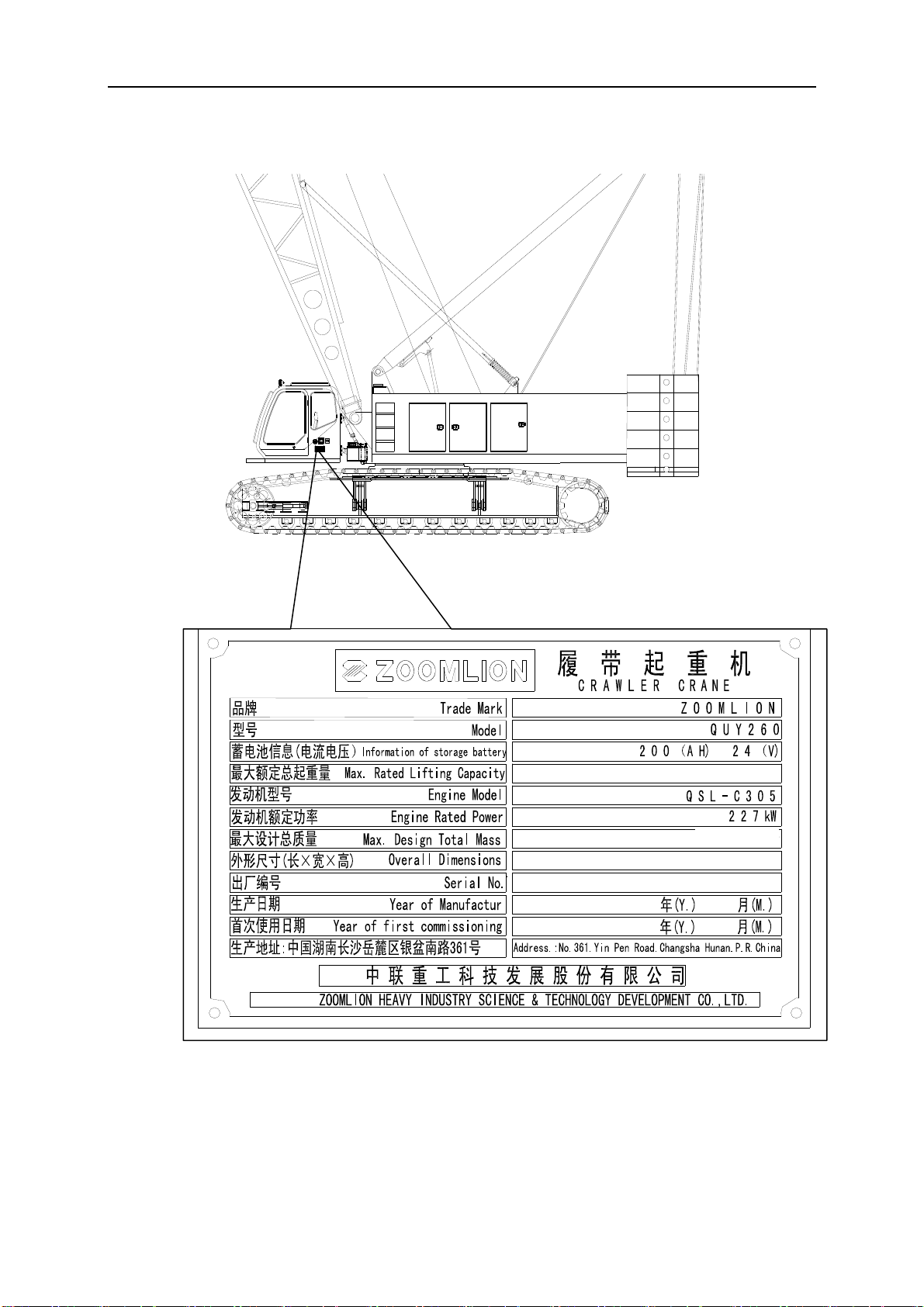
2.1 Product model
2.1.1 Product name plate and its position
2.1.2 Engine type and its manufacturer
2.2 Terminology
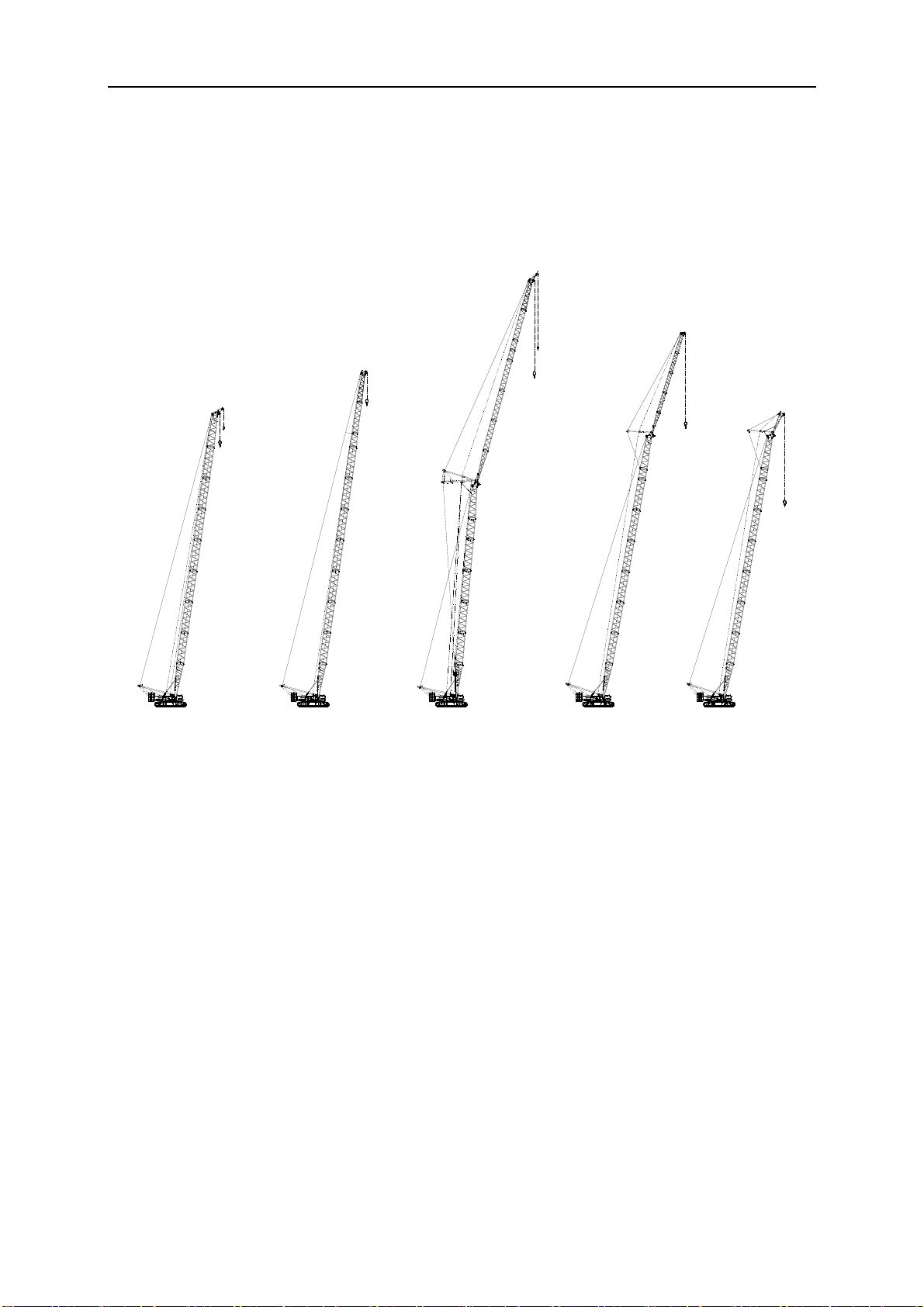
2.2.1 Boom configuration
2.2.2 Description of component parts
2.3 Product description
2.3.1 Crawler travel gear
2.3.2 Crane superstructure
2.3.3 Overall dimensions
2.4 Technical data
2.4.1 Main technical parameter
2.4.2 Type of load hook and applicable rope reeving
2.4.3 Hoisting rope reeving and specification of wire rope
2.4.4 Lifting height
2.4.5 Lifting capacity charts
3 Safety Guidelines......................................................................... 0066340-200-03Y.C
3.1 Operational planning
3.2 Safety—Technical Notes
3.2.1 Safety Instructions
3.2.2 Selecting an operating site
3.2.3 Slopes and trenches
3.2.4 Permissible ground pressure
3.2.5 Checking safety measures
3.2.6 Crane operation with a load
3.2.7 Electromagnetic influences
3.2.8 Safety signs
Page 6

QUY260YM/20.1
II
3.2.9 Hand signals for controlling crane operations
4 Crane operation ......................................................................... 0066340-200-04Y.C
4.1 Operating and control instruments
4.1.1 Overview of crane operator’s cab
4.1.2 Left control box
4.1.3 Right control box
4.1.4 Control panel assy
4.2 Instruction for digital display system
4.2.1 Load moment limiter
4.2.2 Display of control system
4.3 Startup of crane
4.3.1 Adjustment of crane operator’s seat
4.3.2 Checks before startup
4.3.3 Turn on power supply
4.3.4 Start engine
4.4 Safety devices
4.4.1 Emergency stop button
4.4.2 Battery master switch
4.4.3 Load moment limiter
4.4.4 Boom angle indicator
4.4.5 Derrick limiter
4.4.6 Lowering limiter
4.4.7 Hoisting limiter
4.4.8 Support cylinder locking device
4.4.9 Overflow valve
4.4.10 Anemometer
4.5 Crane operation
4.5.1 Operation of traveling mechanism
4.5.2 Operation of crane winches
4.5.3 Operation of synchronizing A-frame and main boom derricking winch and
Page 7

QUY260YM/20.1
III
synchronizing reeving winch and working winch
4.5.4 Operation of slewing mechanism
4.5.5 Simultaneous operation
4.5.6 Operation of movements of crane operator’s cab
4.5.7 Auxiliary remote control box
4.5.8 Undercarriage remote control box
4.5.9 Operation of A-frame erection cylinder and mounting cylinder on A-frame
4.5.10 Emergency control box
4.6 Rope reeving
4.6.1 Heavy duty boom (S)
4.6.2 Light duty boom (SL)
4.6.3 Fixed jib on heavy duty boom (SF)
4.6.4 Luffing jib on heavy duty boom (SW)
4.6.5 Main boom derricking rope guidance and reeving
4.6.6 luffing jib derricking rope guidance and reeving
5 Assembly and dismantling................ ........................................ 0066340-200-05Y.C
5.1 Safety-technical notes
5.1.1 Notes on assembly
5.1.2 Checking safety measures
5.1.3 Inspection of wire rope, load hook, rope pulley and anchoring rods
5.1.4 Connecting or disconnecting the hydraulic lines with quick-release couplings
5.1.5 Setting-up and taking-down
5.2 A-frame
5.2.1 Connecting the hydraulic lines to mounting cylinder on A-frame
5.2.2 Operation of A-frame
5.3 Attaching the crawler carriers
5.3.1 Unloading of basic machine
5.3.2 Attaching the first crawler carrier
5.3.3 Attaching the second crawler carrier
5.3.4 Connecting the hydraulic lines to the crawler carrier
5.4 Attaching the central counterweight
5.5 Assembling the rear counterweight
Page 8

QUY260YM/20.1
IV
5.6 Available boom configurations for crawler crane QUY260
5.7 Boom configuration
5.7.1 Heavy duty boom (S)
5.7.2 Light duty boom (SL)
5.7.3 Fixed jib on heavy duty boom (SF)
5.7.4 Heavy fixed jib on heavy duty boom (SFV)
5.7.5 Luffing jib on heavy duty boom (SW)
5.8 Assembly and dismantling of heavy duty boom (S)
5.8.1 Preparations for assembly
5.8.2 Assembling main boom
5.8.3 Connect electrics to main boom
5.8.4 Erecting main boom
5.8.5 Lowering and disassembling the main boom
5.9 Assembly and dismantling of main boom with luffing jib (SW)
5.9.1 Preparations for assembling luffing jib
5.9.2 Assembling main boom with luffing jib
5.9.3 Connect electrics to luffing jib
5.9.4 Erection and set-down of main boom with luffing jib
5.10 Assembly and dismantling of light duty boom (SL)
5.11 Assembly and dismantling of main boom with fixed jib (SF)
5.11.1 Preparations
5.11.2 Assembling main boom with fixed jib
5.11.3 Connect electrics to fixed jib
5.11.4 Erecting and lowering main boom with fixed jib
5.12 Assembly and dismantling of main boom with heavy fixed jib (SFV)
5.13 Assembly and dismantling of tip boom
5.14 Transport dimensions and weights of main components
5.15 Requirement for crane transport
6 Maintenance .............................................................................. 0066340-200-06Y.C
6.1 General
6.1.1 Crane maintenance
6.1.2 Requirements for crane inspection
6.1.3 Attached tools for maintenance
6.2 Superstructure maintenance and inspection plan
Page 9

QUY260YM/20.1
V
6.2.1 Maintain and inspect superstructure every day or every 5 hours
6.2.2 Maintain and inspect superstructure every month or every 100 hours
6.2.3 Maintain and inspect superstructure every 3 months or every 250 hours
6.2.4 Maintain and inspect superstructure every 6 months or every 600 hours
6.3 Undercarriage maintenance and inspection plan
6.3.1 Maintain and inspect undercarriage every day or every 5 hours
6.3.2 Maintain and inspect undercarriage every month or every 100 hours
6.3.3 Maintain and inspect undercarriage every 3 months or every 250 hours
6.3.4 Maintain and inspect undercarriage every 6 months or every 600 hours
6.4 Boom frame maintenance and inspection plan
6.5 Maintenance and inspection for engine
6.6 Instructions for lubrication and oil change
6.6.1 Hydraulic oil
6.6.2 Gear oil
6.6.3 Lubricating grease
6.6.4 Engine oil
6.6.5 Fuel
6.6.6 Coolant
6.6.7 Lubrication and maintenance of crane in irregular conditions
7 Crane inspections ..................................................................... 0066340-200-07Y.C
7.1 General
7.2 Inspection of steel bearing structures
7.3 Inspection of hosting and luffing winches
7.3.1 Inspections
7.3.2 Requirements for monitoring the winches
7.4 Inspection of load hook
7.5 Inspection of rope pulleys
7.6 Inspection and maintenance of anchoring rods
7.7 Inspection and maintenance of wire rope
7.7.1 Handling and transport of wire rope
Page 10

QUY260YM/20.1
VI
7.7.2 Inspection of wire rope
7.7.3 Discard of wire rope
7.7.4 Maintenance and care of wire rope
7.8 Inspection of oil and fuel tanks
7.9 Inspection of load bearing components
7.10 Inspection of engine
8 Additional equipment. ............................................................... 0066340-200-08Y.C
8.1 Air conditioning
8.1.1 Control panel for air conditioning
8.1.2 Methods for operating air conditioning
8.1.3 Maintenance of air conditioning system
8.2 Media Player
9、Crane inspection log
Page 11

0066340-200-00-20CY
Foreword
Thank you for purchasing ZOOMLION crawler cran
Industry Science & Technology Development Co., Ltd. We are glad to provide high quality and
high-efficiency service for you.
The operating manual are intended to put you in a position to operate the crane safely and utilize
its capabilities to the fullest extend possible.
Certain terms are used in the operating manual, and in order to avoid misunderstandings while
operating, these terms should be used consistently.
Danger: Only qualified and especially trained personnel are permitted to work on the crane!
If this is not assured, the chance of causing a serious accident is greatly
increased!
All regulations and guidelines applicable to the job site, such as accident prevention regulations
and all guidelines and regulations stated in the Operating Manual must be strictly adhered to.
All accident prevention and operating guidelines and regulations, etc. assume that the crane is
strictly used for lifting and transporting of loads, which are not stuck. Any other application or use
does not constitute specified and proper use.
Any risks associated with unspecified and improper use are the sole responsibility of the crane’s
owner, operator or user.
e produced by Changsha Zoomlion Heavy
Using this instructions in the manual:
·makes it easier to become familiar with the crane
··avoids malfunctions due to improper operation
Observing these instructions in the manual:
·increases reliability in operations
·extends the service life of the crane
·reduces repair costs and down-time
Always keep the operating manual handy in the driver’s and crane cab-it is an integral part of the
crane. Operate this crane if you are well familiarized with the capabilities and limitations of the
crane, and always follow these operating instructions.
If you have received additional information about the crane from us, e.g. in the form of technical
information letters, then this information must also be followed and kept with the operating manual.
If there is anything in the operating manual or the individual chapters that you do not understand,
please do no hesitate to ask us or our agents before you begin operation.
No parts of the operating manual may be copied or distributed, nor used for competitive purposes.
Page 12

0066340-200-00-20CY
All rights are expressly reserved in
The content with respect to the safety is marked with“
book are onl
The operating manual must be read and the regulations in it must be observed by all persons
operating, maintaining, or otherwise working in any capacity on this crane.
The employer shall comply with the manufacturer's specifications and limitations applicable to
the operation of any and all cranes and derricks. Where manufacturer's specifications are not
available, the limitations assigned to the equipment shall be based on the determinations of a
qualified engineer competent in this field and such determinations will be appropriately
documented and recorded. Attachments used with cranes shall not exceed the capacity, rating, or
scope recommended by the manufacturer.
A thorough, annual inspection of the hoisting machinery shall be made by a competent
person, or by a government or private agency recognized by the U.S. Department of Labor. The
employer shall maintain a record of the dates and results of inspections for each hoisting machine
and piece of equipment.
Notes:
y the conventional contents.
accordance with copyright laws.
”, the safety instructions involved in the
The following terms that are used in the operating manual “Note”, “Caution”, and “Danger” are
intended to point out certain important rules of conduct to all persons who work with the crane.
The term “Note” is used whenever the observance of certain instructions or notes is economically
meaningful to the utilization of the crane.
The term “Caution” is used whenever damage to the crane can occur if the operating instruction(s)
is not observed and adhered to.
The term “Danger” is used whenever the nonobservance of the warning given may insure or lead
to the death of persons and damaged to the crane.
Safety device
The safety devices built into the crane system deserve your special attention. They must always
be checked to see that they are functioning properly. If they do not function or function incorrectly,
the crane may not be operated. Your motto must always be Safety First.
Caution:
When welding work is conducted on crane, the operator should unplug all power source plugs of
controllers, otherwise, he should bear all consequences incurred.
Page 13

Chapter1
Safety
instructions
Page 14

1.1 Notes
0066340-200-01Y.C
a) Read this manual
and familiarize yourself with any associated documentation before
operating this product.
b) Ensure that a copy of this manual is available for any persons installing, using,
maintaining or repairing this equipment.
Training should be provided to ensure safe working practices.
Initial commissioning and staring must only be undertaken by a competent person who
has read and fully understands the information provided in the manual pack.
c) To avoid the risk of electric shock always isolate this equipment from the supply prior to
carrying out any maintenance adjustment or removing any guards or covers.
d) Always follow the procedures outlined in the operating and maintenance instruction.
e) If in doubt ask, do not take personal risk.
f) Only trained personal can be allowed to install, set, operate, maintain, and decommission
this equipment.
1.2 Alarms and warnings
a) You can be injured if you do not obey the safety instructions as indicated on warning
stickers.
b) Ensure that safety instructions and warnings attached to the plant are always complete
and perfectly legible
c) Keep warnings and instruction labels clean.
d) Replace unreadable or missing labels with new ones before operating the plant. Make
sure replacement parts include warning or instruction labels where necessary.
Caution:
T
o assure personnel safety, all safety instructions and warnings should be observed; for the
position of labels and warni
1.3 Component Safety F
ngs, please refer to Chapter 3 “Safety Guidelines”
eatures
a) Do not use this equipment with guards removed or incorrectly fastened.
b) Do not use this equipment with safety devices maladjusted or removed.
c) Do not use this equipment before the portable fire extinguisher with a basic minimum
extinguisher rating of 5 BC is installed in the cab and minimum 10 BC outside the cab.
1.4 Features for Operator Saf
a) Safety components – crane emergency stop buttons. Ensure all Guards are bolted down.
Page 15

0066340-200-01Y.C
b) S
teps, handrails, tread plates and fixed guards are provided where personnel are
required to climb on the machine.
1.5 Environmental safety
a) It is essential that the service intervals detailed in the maintenance procedures are
followed to ensure that engine emission are kept to a minimum.
b) Consumable materials
1) Diesel spillages must be dealt with immediately.
2) Only use the Lubricating Oils recommended in the maintenance schedule.
3) Local and National regulations must be observed when disposing of waste.
4) Improperly disposing of waste can threaten the environment and ecology and is
illegal.
5) Potentially harmful waste used on this equipment includes such items as oil, fuel,
coolant, filters and batteries, ect.
6) Use leak proof containers when draining fluids. Do not use food or beverage
containers that may mislead someone into drinking from them.
7) Do not pour waste onto the ground, down a drain or into any water source.
8) Ensure that all consumables and replaced parts are disposed of safely and with
minimum environmental impact.
c) Machine disposal. This machine must only be disposed of at a specialist machine
breaker.
1.6 Personal protective Equipment (PPE)
a) Loose or baggy clothing can get caught in running machinery.
b) Where possible when working close to engines or machinery, only do so when they are
stopped. If this is not practical, remember to keep tools, test equipment and all other parts
of your body well away from the moving parts.
c) For reasons of safety, long hair must be tied back or otherwise secured, garments must
be close fitting and no jewellery such as rings may be worn.
d) Always wear correctly fitting personal protective equipment.
e) Recommended personal protective equipment includes:
1) Hard Hat
2) Safety Glasses/Goggles
3) Hearing Protection
4) Close Fitting Overalls
5) Safety Boots
Page 16

0066340-200-01Y.C
6) Industrial Gloves
7) High Visibility Vest or Jacket
1.7 Measured Noise Level
The product and local conditions will affect the noise levels.
The sound pressure level and sound power level, measured using EN13000 Annex G and
2000/14/ EC standards is respectively 73.9dB (A) and 107dB (A)
The sound pressure level measured using ISO 7731 at the position
device is 97.7dB(A).
3′3″
away from th
e warning
1.8 Vibration Levels
Suit
able seating has been installed to reduce the risk of whole body vibrations, in line with
current industry standards.
The crane body vibrations, measured using ISO 2631-1 under normal operating condition, is A(1):
1.3m/s
2
,A(4):0.6m/s2,A(8):0.4m/s
2
1.9 Organizational Safety Measures
This vehicle must only be driven and the crane operated by a suitably qualified operative
a)
who holds a current license in line with National/ International legislation.
b) Understand the service procedure before doing wor k. Keep area clean and dry.
c) Never lubricate, clean, service or adjust machinery while it is moving(excluding central
lubrication).
d) Keep hands, feet and clothing clear of power driven parts and in running nip-points.
e) Keep all parts in good condition. Ensure that all parts are properly installed. Fix damage
immediately. Replace worn and broken parts. Removed any build up of grease, oil and
debris.
f) Disconnect battery groun d cable befor e making adjustments on electrical systems.
g) Disconnect battery ground cable and ECM connecting cable and unplug all plugs of
controllers before welding on machine.
h) During maintenance only use the correct tool for the job.
i) Never make any modifications, additions or conversions which might affect safety without
the manufacturer’s approval.
j) In the event of safety relevant modifications or changes in the beha vior of the machine
during operation, stop the machine and lock out immediately and report the malfunction
to the competent authority/ person.
k) No modifications or additions which affect the capacity or safe operation of the equipment
shall be made by the employer without the manufacturer's written approval. If such
modifications or changes are made, the capacity, operation, and maintenance instruction
Page 17

0066340-200-01Y.C
plates, tags,
or decals, shall be changed accordingly. In no case shall the original safety
factor of the equipment be reduced.
1.10 Personnel Qualification, Requirements and Responsibilities
a) Any work on and/ or with the machine must be executed by trained, reliable and
authorized personnel only.
b) Maintenance work must only be undertaken by suitable qualified engineers with specialist
knowledge of this equipment.
c) Work on the hydraulic system must be carried out only by personnel with special
knowledge and experience of hydraulic equipment.
1.11 Safety Advice Regarding Specific Operational Phases
a) Standard operation
1) Take necessary precautions to ensure that the machine is used only when in a safe
and reliable state.
2) Operate the machine only for it’s designed purpose and only if all guarding, protective
and safety orientated devices, emergency shut-off equipment, sound proofing
elements and exhausts, are in place and fully functional.
3) Ensure that any local barriers erected to stop unauthorized entry to this equipment
are in place.
4) Before starting the engine ensures it is safe to do so.
b) Malfunction
In the event of any malfunction or operational difficulty, stop the machine immediately.
c) Unguarded areas
1) In-running nip points on moving machinery can cause serious injury or eve n death.
2) Do not reach into unguarded machiner y. Your arm could be pulled in and amputated.
3) Switch off the machine before removing any safety devices or guarding.
4) Limit access to the machine and its surrounds where appropriate erect barrier guards
to reduce the risk of residual mechanical hazards, falling lifted loads.
1.12 Machine maintenance and repairs
Observe the adjusting, maintenance and intervals set out in these operating instructions,
except where:
1) Warning, horn/ light/ gauge or indicator calls for immediate action.
2) Adverse conditions necessitate more frequent servicing.
3) Always read instructions supplied with replacement of parts and equipment. Ensure
Page 18

0066340-200-01Y.C
only properly
trained personnel undertake these tasks.
a) Isolation
When undertaking maintenance and repair work, the plant must be first made safe.
1) Switch off the engine and remove the ignition key.
2) Attaching a warning sign(s) to the plant in appropriate positions.
b) Maintenance site conditions
Prior to staring any maintenance work, ensure the machine is positioned on stable and
level ground and has been secured against inadvertent movement and bucking.
c) Replacement and removal of components
1) Always observe handling instructions itemized in this manual, the Original Equipment
Manufacturer’s Manuals or the Spare Parts Supplier’s instructions.
2) Never allow untrained staff to attempt to remove or replace any part of the plant.
3) The removal of large or heavy components without adequate lifting equipment is
prohibited.
4) To avoid the risk of accidents, individual parts and large assemblies being moved for
replacement purposes should be carefully attached to lifting tackle and secured. Use
only suitable and technically adequate lifting gear supplied or approved by the
supplier.
5) Never work or stand under suspended loads.
6) Limit access to the machine and its surrounds where appropriate erect barrier guards
to reduce the risk of residual mechanical hazards, falling lifted loads.
d) Climbing, falling
1) Falling from and/ or onto this machine could cause injury or even death.
2) Never climb on the machine whilst it is in operation.
3) Always keep the area around the machine clear of debris and trip hazards.
4) Beware of moving equipment in the vicinity of the machine.
5) For carrying out overhead assembly work always use specially designed or otherwise
safety-oriented ladders and working platforms.
6) Only use any walkway/ p latforms provided on the machine or on an approved safe
and secure platform.
3′3″
7) Only use CE certified safety harness when reaching any points
the ground le
vel.
or more above
8) Keep all handles, steps, handrails, platforms, landing and ladders free from dirt, oil,
Page 19

snow and ice.
0066340-200-01Y.C
Safety consideration d
e)
uring advanced maintenance
1) Prior to undertaking all but normal planned maintenance activities, it is essential that
a method statement regarding safe working practices for the job in hand is produced.
2) Restrict access to the maintenance area to essential staff only. Where appropriate
erect barrier guards and post warnings.
3) The fastening of loads and instructing of crane operators should be entrusted to
qualified persons only.
4) If a marshal is used to provide instructions, the marshal must be within sight or sound
of the operator with an all round view of the operation.
5) Always ensure that any safety fitment such as locking wedges, securing chains, bars
or struts are utilized as indicated in the operating instructions.
6) Particularly make sure that any part of the plant raised for any reason is prevente d
from falling by securing in a safe reliable manner.
7) Never work under unsupported equip m ent.
8) Never work alone.
f) Safety consideration during cleaning
1) This equipment must be isolated prior to cleaning.
2) Do not direct power washers near or into control boxes and devices.
3) After cleaning, examine all fuel, lubricant, and hydraulic fluid lines for leaks, loose
connections, chafe marks and damage. Any defects found must be rectified without
delay.
g) Removal of safety devices and guards
1) All safety devices (control device or guard) temporarily removed for set-up,
maintenance or repair purposes must be refitted and checked immediately upon
completion of the maintenance and repair work prior to operation.
2) Never operate the machine with safety devices and guards removed or u nsecured.
3) Always report any defects regarding guards, safety device or control devices.
h) Safety when refilling
1) Only refuel with diesel from approved storage and supply equipment.
2) Diesel fuel is flammable.
3) Never remove the filler cop, or refuel, with the engine running.
4) Never add gasoline or any other fuel s mixed to diesel because of increased fire or
Page 20

explosion risks and damage to the engine.
5)
Do not carry out maintenance on the fuel system near naked lights or sources of
sparks, such as welding equipment or whilst smoking.
6) To avoid spillages use drip trays.
7) Immediately clear up spilt fuel and dispose of correctly to minimize any environmental
impact.
1.13 Special Hazards
1.13.1 Electrical energy
a) External considerations and hazards
When working with the machine, maintain a safe distance form overhead electric lines.
If overhead cables are in the vicinity a risk assessment must be completed prior to
operating this equipment.
If your machine comes into contact with a live wire:
0066340-200-01Y.C
1) Vacate the area.
2) Warn others against approaching and touching the machine.
3) Report the incident and have the live wire de-energized.
b) Machine - Electrical
The electrical equipment of the plant is be inspected and checked at regular intervals.
Defects such as loose connections or scorched or otherwise damaged cables must be
rectified immediately. Use only original fuses with the specified current rating. Switch off
the machine immediately if trouble occurs in the electrical system.
This plant is wired on a negative earth. Always observe correct polarity.
c) Battery
1) Always disconnect battery leads before carrying out any maintenance to the electrical
system.
2) Recharge the battery in a well ventilated area.
3) The battery contains sulphuric acid, an electrolyte which can cause severe burns and
produce explosive gases.
4) Avoid contact with the skin, eyes or clothing.
5) No smoking when maintaining battery.
6) Wear appropriate PPE.
Page 21

0066340-200-01Y.C
1.13.2 Gas, dust, steam, smoke and
noise
a) Always operate internal combustion engines out of doors or in a well ventilated area.
b) If plant is operated for maintenance purposes in an enclosed area, ensur e that there is
sufficient ventilation or provide forced ventilation.
c) Observe the regulations in force at the respective site.
d) Dust found on the plant or produced during work on the plant must not be removed by
blowing with compressed air.
e) Toxic dust/ waste must only be handled by authorized persons dampened, placed in a
sealed container and marked, to ensure safe disposal.
1.13.3 Welding or naked flames
a) Welding, flame cutting and grinding work on the plant must only be carried out if this has
been expressly authorized, as there may be a risk of explosion and fire.
b) No welding should be undertaken on this equipment as it will affect its structural integrity.
c) Avoid all naked flames in the vicinity of this equipment.
1.13.4 Hydraulic equipment
a) Work on hydraulic system must be carried out by persons having special knowledge and
experience of hydraulic system.
b) Check all lines, hoses and screwed connections regularly for leaks and obvious damage.
Repair damage immediately. Splashed oil may cause injury and fire.
c) Always relieve pressure from the hydraulic system before carrying out any kind of
maintenance or adjustment.
d) Depressurize all system sections and pressure pipes to be removed in accordance with
the specific instructions for the unit concerned before carrying out any repair work.
e) Hydraulic lines must be laid and fitted properly. Ensure that no connections are
interchanged. The fittings, lengths and quality of the hoses must comply with the
technical requirements.
f) Only fit replacement components of a type provided by the manufacturer.
g) Always practice extreme cleanliness servicing hydraulic components.
h) Hydraulic fluid under pressure can penetrate the skin causing serious injury. Once the
fluid is injected under the skin, seek medical help immediately.
i) If the fluid is injected under the skin, seek medical help immediately.
1.13.5. Necessary clothing and personal belongings shall be stored in such a manner as to not
interfere with access or operation.
1.13.6.Tools, oil cans, waste, extra fuses, and other necessary articles shall be stored in the tool
Page 22

0066340-200-01Y.C
box, and shall not be permitted to lie loose in or ab
out the cab.
1.13.7.The employer shall comply with Power Crane and Shovel Association Mobile Hydraulic
Crane Standard No. 2.
1.13.8.Operating and maintenance personnel shall be made familiar with the use and care of the
fire extinguishers provided.
1.13.9 Modified, altered and / or repaired cranes
the employer of the crane must conform with the requirements of 1926:1412
1.13.10 Wire rope inspections
the employer of the crane must conform with the requirements of wire rope inspections as per
the requirements of 1926.1413
1.13.11 Wire rope—selection and installation criteria
the employer of the crane must conform with the requirements of wire rope selection and
installation as per the requirements of 1926.1414
Page 23

Chapter 2 Description of the crane
Page 24
0066340-20
2.1 Product model
2.1.1 Product name plate and its position
0-02Y.C
Page 25
0066340-20
0-02Y.C
2.1.2 Engine type and it
QSL-C305——CUMMINS, USA
2.2 Terminology
2.2.1Boom configuration
s manufacturer
S
SL SW SF SFV
Page 26

0066340-20
Instructions for boom configuration
0-02Y.C
Configuratio
no.
SL Light duty boom
SW
SF Fixed ji
SFV
n
S Heavy duty boom
Heavy fixed
Description
Luffing jib on heavy duty
boom
b on heavy duty b
boom
oom
jib on heavy duty
Parameters
S =
65′7″~272′3″
282′1″~311′8″
SL
=
S =
75′5″~203′4″
68′10″~196′10″
W =
S =
95′1″~252′6″
34′9″~98′5″
F =
134′5″~252′6″
S =
19′8″
FV =
Page 27

0066340-20
0-02Y.C
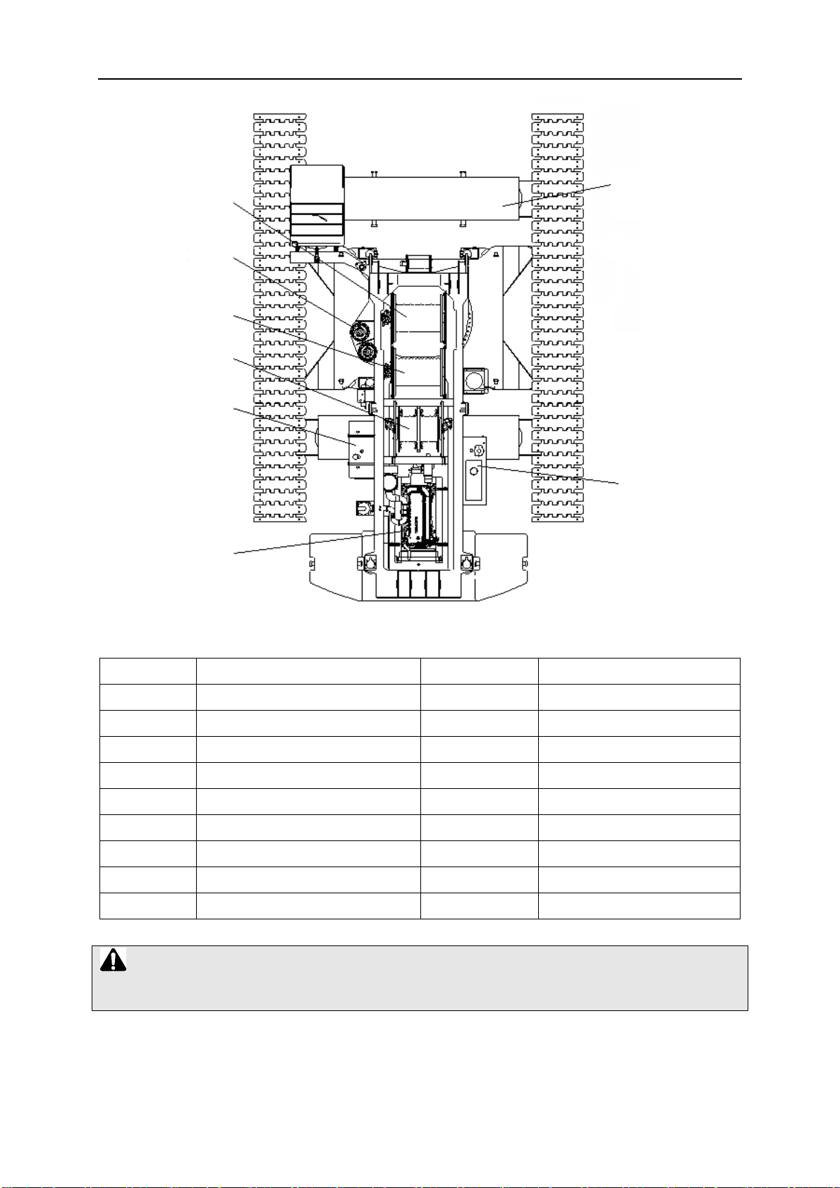
2.2.2 Description of component p
1.2
arts
2.8
1.1
2.7
.1
2.2 2.3 2.4 2.5
2
Page 28
0066340-20
0-02Y.C
1.3
1.5
1.4
1.6
1.7
1.9
2.6
1.8
Description of component part
Part No. Description Part No. Description
1.1
1.2 Counterweig
1.3
1.4 Hoisting winch 2 2.4 Tr
1.5 Slewing redu
1.6 Main boom de
1.7 Diesel oil ta
1.8 Hydraulic oil t
1.9 Engine
Note:
The luffing jib derricking winch (2.8) is optional.
Operato
Hoisting winch 1 2.3 T
’s cab 2.1 Drive sprocket
r
ht 2.2 Crawler carrier
cer 2.5 Driven sprocket
rricking winch 2.6 Central counterweight
nk 2.7 Track pad
ank 2.8 Luffing jib derricking winch
s
r
ack carrier roller
ack roller
Page 29

2.3 Product description
0066340-20
0-02Y.C
2.3.1 Craw
2.3.2 Crane superstructure
ler travel gear
Travel gear
Maintenance-free crawler travel gear with
Distance between track center:
T
The crawlers driven independently through hydraulic motor and planetary reducer;
Allow such traveling moments available as traveling straight ahead/ backwards, turning on
the spot, turning with a crawler and differential steering
Drive performance
Infinitely variable speed from 0 to 0.98km/h
Slewing table
Self-manufactured and high-rigid welded structure of high-strength structural steel;
Connected to undercarriage via a 3-row roller slewing ring for 360°continuous rotation
Crane engine
ravel
devic
e
20′11″
3′11″ track pad;
6-cylinder four cycle diesel engine, manufactured by America Cummins, type QSL9-C305;
displacement :8.9L water-cooled, turbo charge, air cooling(air- air)
Rated power/rotational speed: 227kW (305HP) / 2000rpm;
Maximum torque/ rotational speed: 1505N.m /1400rpm
Type of starting equipment and voltage if applicable----- staring motor and 24V voltage
Type of generating equipment including---24V DC, negative ground, 2 batteries of 195AH
each.
fuel tank capacity------700L
altitude limitations-----≤
ol
ing system refill capacity------44L
co
lubrication oil refill capacity-----23L
slope operation limitations-----30% of grade
Crane drive
Driving force, provided by diesel engine, is transmitted by transfer case to a dual variable
9997′5″
pump, a piston variable pump and a dual gear pump.
Crane control
CAN bus technology connecting engine, PLC controller and digital display;
All motions controlled independently by two 4-way control levers.
Page 30

0066340-20
Win
ches
Used in hoisting mechanism and derricking mechanism
Slewing mechanism
Hydraulically powered by axial piston variable displacement pump and planetary reducer with
spring-loaded multi-disk brake;
The infinitely variable slewing speed from 0 to 1.0rpm by closed oil circuit.
Hoisting mechanism
available line pull------210kN(the six layer)
permissible line pull------147kN(the six layer)
available line speed-----109m/min(the six layer)
0-02Y.C
drum pitch diameter---rope
spooling capacity----
Rear counterw
187400 Ib
counterweight base plate;
Fitted on the tail end of crane superstructure
Crane operator’s cab
Pressure-proof steel construction cab with safety glass;
With operator’s seat, operating and control instruments;
Swiveling sideways and tiltable backwards
Safety equipment
Angle indicator, load moment limiter, hoisting limit switch, overflow valves, support cylinder
locking device, derricking (luffing) limiter and so on
Electrical system
Single wire system; 24v DC; negative ground
The crane classification group is A1, and the classification group of working mechanism are:
, consisting
2′1″
1968′‐1″
eight
of 10 counterweig
ht plates
14600 Ib
each and a
41900 Ib
traveling mechanism (M1), slewing mechanism (M2), hoisting mechanism (M3) and
derricking mechanism (M2).
Pumps
Type --- -- - A8V0140LA1H2/63R1-NZG05F174
engine to pump speed ratio-----1.04
flow, L/min (gpm) at specified pressure, kPA (p si), and speed, rpm----
maximu
m working pressure------42mpa
--2*28
5 L/min
Page 31

2.3.3 Overall dimensions
0066340-20
0-02Y.C
echnical data
2.4 T
2.4.1 Main technical parameter
a) Weight
Basic machine
Rear counterweight
Central counterweight
Crawler
carrier
187400 Ib
105800 Ib
70600 Ib
55100 Ib
2×
Page 32

b) Speed
0066340-20
0-02Y.C
Mechanism
Hoisting winch 1
Hoisting winch 2
Main boom derricking
winch
Luffing jib derricking
winch
Speed Rope diameter
360′9″
/min (maximum speed of single rope, the
6th rope layer)
360′9″
/min (maximum speed of single rope, the 6th
rope layer)
m/min (maximum speed of single rope, the
95′1″
6th rope layer)
150′10″
/min (maximum
6
speed of single rope, the
th
rope layer
Slewing mechanism
Gradeability 30%
2.4.2 Type o
f load hook and applicable rope reeving
Type of load hook Maximum rope reeving
573300 Ib 20
352800 Ib /220500 Ib 12/8
110250 Ib
4 3900
6200
)
0 - 1.0rpm
Φ
Φ
Φ
Φ
1.12″
1.12″
1.12″
1.12″
Weight of load hook (
9300
Ib)
66150 Ib 2 2400
35280 Ib 1 2000
2.4.3 Hoisting rope reeving and specification of wi
2.4.3.1 Hoisting rope reeving table
Reeving
1
2
3
4
5
6
7
Lifting
capacity
28665
61740
9
0
261
121275
149940
178605
2
70
072
Reeving
8
9
10
11
12
13
14
Note:
1. If crane is working with ho
table, single hoisting ro
isting rope reeving less than the value listed in the above
pe load must be checked to make sure that the max.
permissible load capacity of single hoisting rope is
re rope
Lifting
capacity
233730
260190
2
50
866
0
31311
337365
363825
3
80
880
Reeving
15
16
17
18
19
20
not exceeded.
Lifting
capacity
410130
434385
4
35
564
478485
500535
573300
2. Maximum permissible loa
d capacity of single rope is
33100 Ib
.
Page 33

0066340-20
0-02Y.C
2.4.3.2 Specification of
Description and
intended use
Torsion-resist
Nominal rope
diameter
Rope length
Direction an
2.4.3.3 Use length of hoisting rope and derricking rope
ance or
not
d type of
lay
When A-fram
of derricking rope is about
When A-frame tilt
horizontal line reaches the minimum value), the longest length of derricking rope is about
705′2″
Crane operation wi
reeving is 12, the longest possible hoisting rope is
wire rope
Hoisting rope for
winch1
Yes Yes No
Φ1.12″
1574′4″
Lef
t-hand lan
e remains in its transport position on the superstructure, the shortest length
s forwards to maximum angle (i.e., the angle of A-frame to front
th main boom: when main boom length is
g lay Left-hand lang lay Right-hand ordinary lay
;
65′7″
Hoisting rope for winch
Φ1.12″
1574′4″
2
1508′9″
Derricking rope
Φ1.12″
459′2″
×2
.
114′9″ and the rope
w
Crane operation
boom length is
possible hoisting rope is
Crane operation wi
jib length is
39′4″
ith main boom and luffing jib: when main boom angle is 85°, main
154′1″
, luffing jib length is
th main boom and fixed jib: when main boom length is
and the rope reeving is
1098′9″
.
88′6″
and the rope reeving is 5, the longe
252′6″
3, the longest possible hoisting rope is
, fix
1197′2″
st
ed
.
Page 34

0066340-20
0-02Y.C
2.4.4 Lifting
Note: The main boom lifting height curve is draw
2.4.4.1 Lift
height
ing height on S&SL boom
n without considering boom deflection.
Note:
1. The horizontal direction indicates working radius (in ft) and the vertical direction indicates
lifting height (in ft).
2. For S boom configuration, the heavy
For SL boo
m configuration, the light duty boom length varies from
duty boom length varies from
65′7″~272′3″
282′1″~311′8″
;
.
Page 35

0066340-20
0-02Y.C
2.4.4.2 Liftin
g height SF boom/fixed jib combination
Note:
1. The horizontal direction indicates working radius (in ft and the
indicates lifting height (in ft).
2. For SF boom configura
fixed jib length varies from
tion, the main boom length varies from
34′9″~98′5″
and offset angle of fixed jib is 10
vertical direction
95′1″~252′6″
, the
° and 30°.
Page 36

0066340-20
0-02Y.C
2.4.4.3 Liftin
g height on SFV boom/ heavy fixed jib combination
Note:
1. The horizont
indicates lifting height (in ft).
2. For SFV bo
heavy fixed jib length is
al direction indicates working radius (in ft) and the vertical direction
om configu
r
ation, the main boom length varies from
19′8″
, and offset angle of fixed jib is 14
134′5″~252′6″
° and 20°.
th
e
Page 37

0066340-20
0-02Y.C
2.4.4.4 Liftin
g height on SW boom/ luffing jib combination
Note:
1. The horizontal direction indicates working radius (in ft)
indicates lifting height (in ft).
For SW boom configurat
ion, the main boom length varies from
and the vertical direction
75′5″~203′4″
Page 38

0066340-20
0-02Y.C
2. , and the luff
2.4.5 Lifting
The valid lifting capacity charts for all machine configurations can be found in a special
volume.
capacity charts
Note:
1. The values in lif
2. The value in lif
which is the maximum permitted lifting cap
configurations. It in
handling devices.
ing jib length varies from
ting capacity charts are applicable to 360° working range.
ting capacity charts is the rated total lifting capacity of crane,
cludes the weight of load hook, wire rope and other load
68′10″~196′10″.
acity under various boom
Rated total
capacity =
lifting
Rated lifting
capacity
(Actual load)
+
(Weight of load hook,
wire rope
handling devices)
and other load
3. The radius in lif
slewing ring to centerline of hook when crane is lo
4.
The rated t
different boo
ting capacity charts is the horizontal distance from central axle of
aded.
o
tal lifting capacity indicates the crane’s lifting capacity under
m configurations when it is operated on firm and flat ground.
Page 39

Chapter 3
Safety Guidelines
Page 40

3.1 Operational planning
006364
0-200-03.CY
In addition to a perfectly working crane and a w
important precondition for safe and reliable crane operation.
The crane operator must obtain or receive the necessary information (familiarize himself with
the operating manual, basic knowledge about pneumatic, electrical and hydraulic drive, and
notes for safe operation as well as operating environment) before starting the crane operation,
in particular:
a) Clearly define the area of responsibility of all personnel concerned.
b) Type of crane operation and required working mode;
c) Distance between the lifting points and surrounding buildings;
d) Influence of communal facilities( including the overhead high/low voltage lines and
underground gas pipes);
e) Space requirements at the work site
f) Movement restrictions due to surrounding structures(e.g. is there another crane nearby in
working);
g) Number, weight, dimensions, material of load(s) to be lifted
ell-trained crew, operational planning is an
h) Required lifting height and slewing radius
i) Load-bearing capacity of soil or surface to be operated upon
j) Height and widths of thoroughfares leading to the site;
k) Other factors affecting the site (e.g. weather, live lines, etc.);
l) Communication means adopted between signalman and crane oper ator;
m) Take appropriate measures to keep people unconcerned and equipment away from the
working area;
n) Equipment modifications: the employer of the equipment shall adhere to the requirements
of 1926:1434
Based on the above information, the crane operator must assemble the equipment required to
operate the crane:
- Required working mode for crane operation
- Hook blocks/load hook (with or without hook blocks)
- Counterweight
Page 41

006364
Caution:
0-200-03.CY
1. A correct and complete oper
operation of the machine. The op
ational p
oper
the operation and considering all the factors that
operation.
If
2.
the crane operator do
may prove impossible to carry out the intended work and accident
result!
3.2 Safety—
3.2.1 Safety Instructions
3.2.1.1 Safety instructions for crane operator
Technical Notes
The crane operator’s primary responsibility is to control, operate and adjust the crane in a
manner that is safe for both himself and others. Therefore the crane operator should meet
the following requirements.
anning by obtaining and analyzing all necessary information about
l
ational planning is vital for safe and problem-free
eration planner must plan a safe and reliable
es not possess all necessary and required information, it
may impair safety of crane
s may be the
a) The operator must be familiar with the operating manual for the crane, and know the
working principle, structure performance and the safety devices’ function, as well as
master the operation essentials and maintenance skills.
b) The operator should inspect brake, hook, wire rope and safety device befor e operating
the crane. Any irregularities detected during inspection should be removed
immediately.
c) The operator must focus his attention on his work during operation and is forbidden to
chat with others. Generally speaking, operator can only follow signal sent out by
appointed persons. For a stop signal, the operator should obey it at all times, no matter
who gives it. He should refuse to accept signal which violates operation regulations.
Page 42

006364
0-200-03.CY
Stop the cra
d) Operator who is in low spirits or poor healthy is not allowed to operate the crane.
e) Crane operator and slinger/banks man should be familiar with safety rules, signals and
symbols. Prohibit drinking and driving.
f) Be qualified with the work in hearing, eyesight and reaction ability; be strong enough to
operate safely, and has the ability to estimate distance, height and clearance correctly.
g) Be familiar with the usage of fire extinguishing equipment and be well trained; know
how to survive under emergent conditions.
h) Make sure that only authorized personnel are allowed to operate the crane.
ne immediately if somebody is found climbing the crane.
To make sure that the crane is kept in good working order, the crane operator should
perform the following checks before operating the crane:
a) Check the daily record of work to ensure that all regular inspections, maintenance and
repair work is performed.
b) Check the hoisting limiter, boom angle indicator, tilting-back support and other safety
equipment for functional work;
c) Check the load-bearing parts carefully, such as wire rope (hoisting rope, derricking
rope and sling etc.), boom, outriggers, hook and load handling devices;
d) Check if there are some bolts, nuts and pins lost, and the components are cracked or
damaged.
e) Ensure that no modification has been made to the crane without permission, e.g.,
increase or decrease in counterweight plate and improper repair of boom frame.
f) Check fuel lines and hydraulic oil lines for leakage.
g) Check all control mechanisms for functional work after starting up the engine.
h) Check all control devices for functional work.
i) Check the brakes. Test the braking performance by lifting a load away from the ground and
suspend it in the air for a moment.
j) Check whether lubricating oil, grease or anti-freeze liquid is sufficient.
k) Check for contamination.
Page 43

006364
0-200-03.CY
The
3.2.1.2 Safety instructions for the rigger
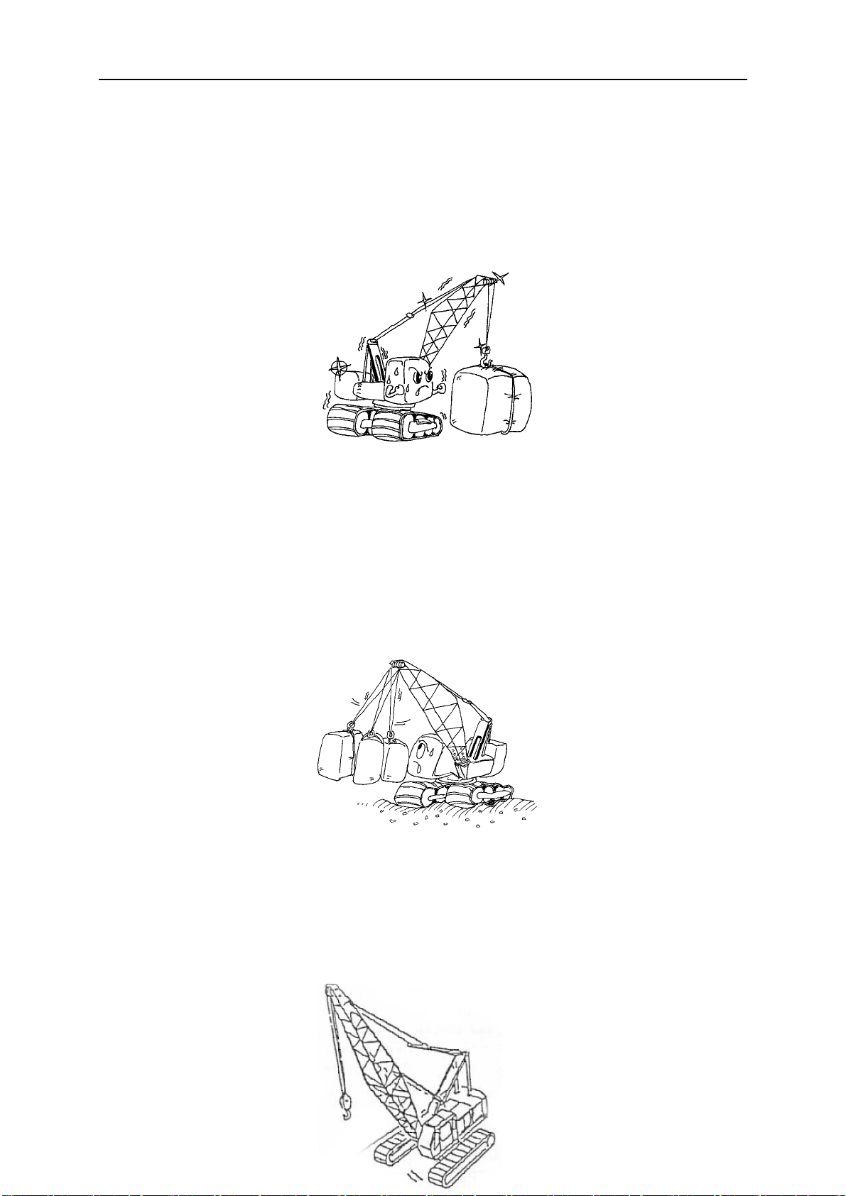
following improper operating errors, which are made again and again while operating,
should be avoided.
a) Slewing too quickly;
b) quick braking of the load;
c) diagonal pulling of the load to be lifted which is still in contact with the ground;
d) Loose wire rope formations;
e) overloading or improperly attaching the load;
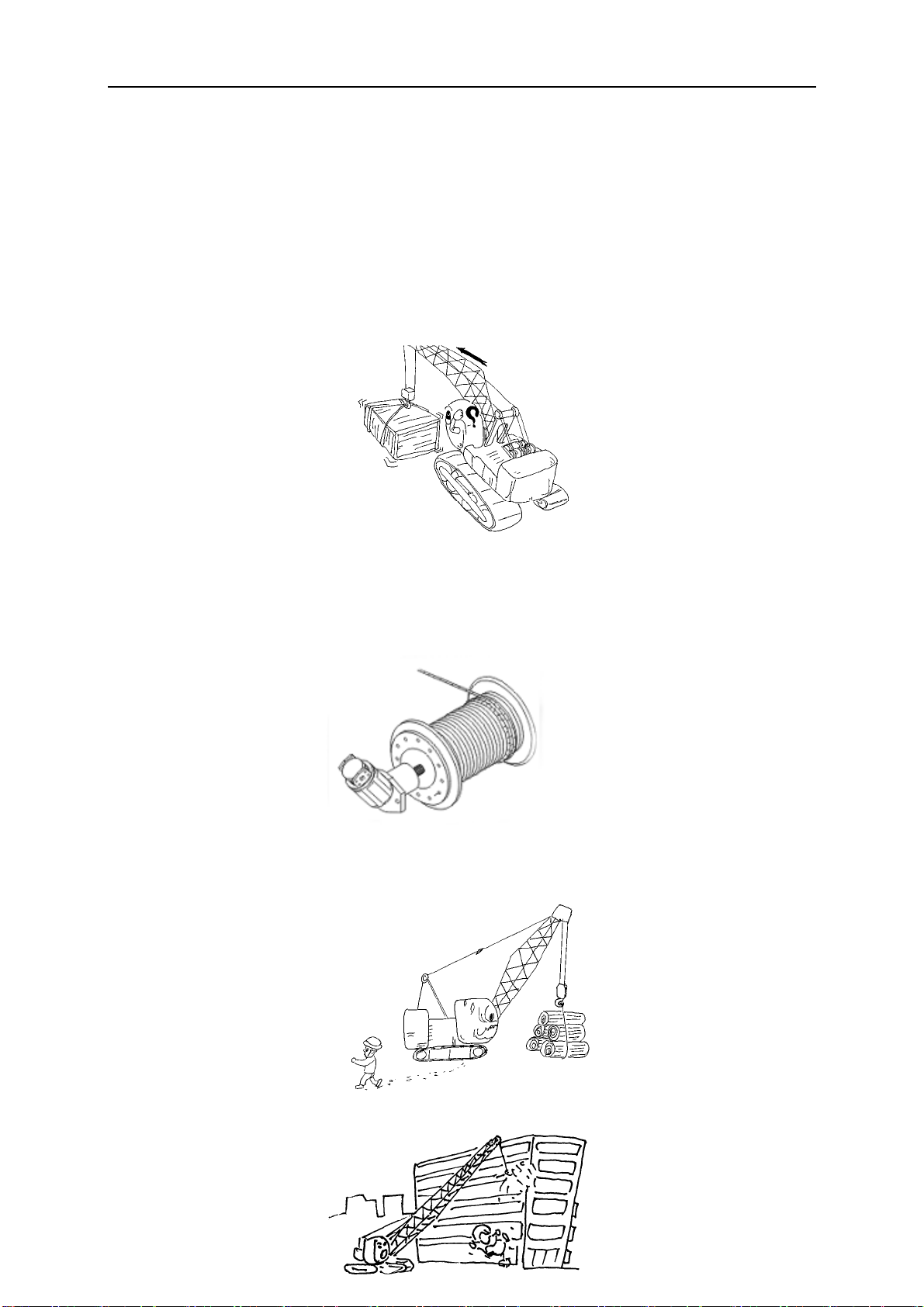
f) driving(or sle wing) too fast with a load, or setting up and loading on an une ven surface;
g) diagonal pulling, breaking away stuck loads;
h) swinging of suspended load, crashing into bridges, roofs or high voltage wiring;
i) Incorrect assembly or disassembly of booms
The rigger’s job is to hang or detach load from hook and to decide which hook or component to
be used in accordance with work plan. rigger also has the responsibility to guide operator’s safe
operation.
Qualifications for rigger:
a) With crane operation certificate;
b) Be qualified with the work in hearing, eyesight and reaction ability;
c) Be strong enough to carry hook or component;
d) Be able to estimate the load, balance the load and judge the distance, height and
clearance correctly;
e) Be trained in the skill of handling load;
f) Be able to choose proper load handling device and components according to the loading
condition;
g) Be trained in hand signals for operation and familiar to use them;
h) Be able to safely use audio equipment (such as interphone) to send out oral order
exactly and clearly;
i) Be capable of conducting the operation of crane to move the load safely;
j) Make sure that only authorized personnel are allowed to carry out work.
Page 44
3.2.1.3 Safet
The main job of signalman is to assist crane operator to carry out safe operation. Potential
damage to property or personal injury could be avoided if the crane operator carries out the
crane movement following the signals given out by appointed signalman. However, only
one signalman may work with the crane operator at a time.
Qualifications for signalman:
a) Familiar with the lifting task so as to cooperate with crane operator and other workers;
b) Make sure that only authorized personnel are allowed to carry out
c) Be qualified with the work in hearing, eyesight and reaction;
d) Be able to estimate the distance, height and clearance correctly;
e) Be trained in hand signals for operating and familiar to use them;
f) Use standard hand signals for crane operation. If necessary, use a
006364
y
instructions for the signalman
work;
radio device to send out correct and clear order;
0-200-03.CY
g) Be capable of conducting the operating of crane to move the load safely;
h) Position himself in a safe location from where he can see the whole process of
operation and be seen clearly by the crane operator.
Danger:
In order to assure yourself and
accordance with specified regulations, and
dangers caused by improper op
3.2.1.4 Points for attenti
a) Any unsafe operation must be corrected or any d angerous situations must be reporte d
to supervisor.
b) All the persons in vicinity of crane must observe the acoustic warning signals of the
machine so as to ensure himself and others safety.
c) All the worker must know about the content of task and working sequence;
d) Check whether dangerous situations occur during operation of the machine, and inform
crane operator and signalman of the unsafe factors such as high-voltage power line,
unauthorized persons, obstacles and poor ground conditions.
other perso
eration.
on for crane operating crew
n’s interest, please operate crane in
take precautions against possible
3.2.2 Selecting an operating site
It is very important to choose an appropriate location for crane operation in order to minimize
safety risks. The operating site should be selected so that:
a) crane movement can be carried out within the smallest possible radius;
Page 45

006364
0-200-03.CY
b) no obst
c) the ground an the operating site is able to support expected loads;
acles hinder necessary movements;
d) Accessible areas within the swing radius of the rear of the rota
superstructure of the crane, either permanently or temporarily mounted, shall
be barricaded in such a manner as to prevent an employee from being struck
or crushed by the crane
Danger:
The most essential requirement for safe crane operation is working on firm ground with the
capacity to
3.2.3 Slopes and trenches
The crane may not be set up too close to slopes or
be kept from them depending on the type of soil.
support you loads.
trenches. A safety distance must always
ting
Note:
Safety distance is measured from the foot of the trench and is:
Soft or backfilled soil = 2× depth of trench (A2 = 2×T)
Hard or grown soil = 1×depth of trench (Al = 1×T)
Danger:
If a safe distance is not maintained, the slope or trench must be firmly filled. Otherwise,
there is a danger that the edge of the slope or trench will give away.
3.2.4 Permissible ground pressure
Soil type 10
A) back-filled, not naturally comp
B) Natural soil, apparently undisturbed
acted ground
-1
0 - 1
MPa
Page 46

006364
mud, peat, marshy soil 0
1.
0-200-03.CY
3. non-cohesive, suf
Fine to medium grained sand;
From coarse-grained sand to gra vel
3. cohesive soil:
loamy;
soft;
stiff;
Semi-solid;
hard
4. rock
In cohesive layer order
In massive or column-style shape
C) artificially compacted g
1. a
3. concr
Concrete group B II
with few fissures, in healthy, un-weathered
condition and in a favorable location:
sphalt; 5 - 15
ete concrete group B I;
ficiently compactly layered soil:
round
5
3.0
0
4
0
0
4.0
15
30
50 - 250
350 - 550
Caution:If there is any doubt about the load
site, soil test
3.2.5 Checki
The safety condition of the crane should be checked thoroughly prior to operating the crane,
including:
a) Check whether the ground provi des adequate load-bearing capacity.;
b) Check whether there is sufficient safety clearance to slopes and trenches;
c) Check whether the crane is adjusted to be horizontal;
d) Check whether there are live electrical wires within the working range of the crane.
e) Check whether there are obstacles which will hinder required crane operation.
working radius:
should be carried out, for example, with a penetrometer.
ng safet
measures
y
-bearing capacity of the ground at the operating
Page 47

006364
Caution:
The crane operation belongs to dangerous operation; so much attention should be given to
the working condition of crane before and durin
0-200-03.CY
g crane operation.
3.2.6 Crane operation wi
Before beginning any work, the crane operator must be convinced that the crane is in safe
operating condition. All safety devices, such as load moment limiter, hoist limiter switches,
brakes, etc., are in good working order.
a) The load moment limiter must be set according to the current crane configuration.
b) The load capacities as given in the load lifting capacity tables must be adhered to. The
loads given in the load lifting capacity tables must not be exceeded.
c) The crane operator must know the weight and dimensions of the load before operating
the crane.
d) Load handling devices, lifting equipment and tackle must be in accordance with specified
requirements.
e) It must be ensured that the weight of the hook block and the weight of the tackle are
subtracted from the load given in the lifting capacity table.
Example:
Maximum permissible load according to table
th a load
66150 Ib
Weight
Weight
Actual useful load of the crane
In this case, the load to be lifted may no excee
of the hook block
of the slinging rope
63702 Ib
d
2359 Ib
88 Ib
63702 Ib
Page 48

006364
0-200-03.CY
3.2.6.1 Counterwe
The required counterweight should be installed prior to operation according to specified
requirements.
Danger:
If the counterweight is not installed according to the lifting capacity table, there is a danger
of the crane toppling ove
3.2.6.2 Hoisting gear, hoisting rope
The lifting capacity of the crane is a function of the tension force of the hoisting rope and
hoisting rope reeving. When working with a single cable, the crane can only lift as much of
a load as the hoisting gear is able to pull.
If the load to be lifted is heavier than the hoisting gear is capable of lifting, the hoisting rope
must be configured using block and tackle principles by appropriate reeving between the
pulley head on the boom and the hook block. Possible hoisting rope reeving is listed as
follows:
ight
r.
Hoisting rope reeving
reeving Lifting load reeving lifting load reeving lifting load
1
2
3
4
5
6
7
Caution:
1. If crane is working with hoisting rope reeving less than the value listed in the above table,
single hoisting rope load must be ch
capacity of
28665
61740
92610
121275
1499
40
178605
207270
single hoisting rope is not exceeded.
8
9
10
11
12
13
14
ecked to make sure that the max. permissible lifting
233730
260190
286650
313110
3373
65
363825
388080
15
16
17
18
19
20
410130
434385
456435
478485
5005
573300
35
2. Max.
3. If
the maximum tensile force is exceeded, there is the danger that the rope(s) may break or
that the hoisting
permissible lifting capacity of single hoisting rope is 33075
gear and /or drive motor may be damaged.
Ib
Page 49
3.2.6.3 Crane operation
3.2.6.3.1 Operating conditions
a)
All components of crane are in running-in state at the initial operating period. So, for the
first 100 operating hours, the working load should not be too great and the working speed
should not be too high. The maximum lifting load can not exceed 80% of its rated load.
And the maximum working speed is forbidden.
006364
0-200-03.CY
b) The ground on jobsite should be firm and flat and the gradient should not be greater than
5/1000. The complete vehicle should be level and the supporting ground should not give
away during operating. If the ground is soft, a steel plate should be placed under the track
shoe.
c) The permitted temperature range for crane’s operation is-20℃~40 . Humidity should ℃
not exceed 85%; however, high humidity up to 100% is only permitted for a short period
of time. The crane should be operated and supported on a ground lower than 1000m
above seal level.
Page 50

006364
0-200-03.CY
The maximu
d)
the maximum out-of-service wind speed should be no more than 21m/s when only main
boom is assembled, and no more than 15m/s when fly jib is assembled.
With the following table, the wind force and wind velocity can be estimated correctly:
Wind force Effects of the wind in the inland
Beaufort description m/s
0 Calm
m in-service wind speed should be not more than 9.8m/s during operation;
Wind force beaufort
0~0.2
No wind, smoke rises str
aight up
1 Light air
2
3
4
5
6
7 Stif
8
9 Gale 20.8~
10
Light
breeze
Gentle
breeze
Moderate
breeze
breeze
Strong
breeze
Gale force
Severe
Fresh
f wind
wind
gale
0.4~1.4
1.6~3
3.4~
5.5~7.8
8~10.6
10.8~13.7
13.9~17
17.2~20.6
24.7~
5.3
24.5
28.3
Wind direction is shown only by observing the trail of
smoke, not by the wind sock
Wind can be felt on the face,
sock moves slightly
Leaves and thin twigs move. Wind extends a small
breeze flag.
Swirls up dust and loose paper, moves twigs and thin
branches
Small deciduous trees begin to sway, foam forms at
sea.
Thicker branches move; telephone lines begin to
whistle, umbrellas are difficult to use
Entire trees swaying; difficult to walk into wind
Breaks twigs off trees, walking becomes difficult
Minor damage to property(chimney tops and roofing
tile are blown off)
Trees are uprooted, significant damage to property
the leaves rustle, wind
Page 51

006364
0-200-03.CY
e) When crane
part of crane and overhead power line should comply with the following regulations:
Cutline:
is working near the high-voltage power line, the safe clearance between any
The safe clearance from high-
voltage power lines:
Operation near high-voltage power lines
Up to 50
Over 50 to 200
Over 20
Over 35
Over 500 to 750
Over 750 to 1000
Note: the volue that follows “to” is up to and includes that value ,for example over 5
means up to and including 200kv.
0 to 350
0 to 500
Over 1000
(as established by the utility owner/oper
engineer who is a qualified person with respect
to electrical power transmission and distributiono)
Ft(m)/Note(
10/3.05
15/4.60
/6.10
20
/7.62
25
35
/10.67
45
/13.72
l)
ator or registered professional
Opertion in transit with no load and boom or mast lowered
Ft(m)/Note(l)
0 to 200
Up to 0.75
Over 0.75 to 50
Over 50 to 345
Over 345 to 750
4/1.22
1.83
6/
10/3.05
/4.87
16
Page 52

Over 750 to 1000
006364
0-200-03.CY
/6.10
20
Over 1000
aa) Equipment or machinery
equipment or machines shall be operated proximate to power lines only in accordance with the
following:
bb) For lines rated 50 kV. or below, minimum clearance between the lines and any part of the
crane or load shall be 10 feet; Except where electrical distribution and transmission lines have
been deenergized and visibly grounded at point of work or where insulating barriers, not a part
of or an attachment to the
cc) For lines rated over 50 kV , minimum clearance between the lines and any part of the crane or
load shall be 10 feet plus 0.4 inch for each 1 kV. over 50 kV., or twice the length of the line
insulator, but never less than 10 feet;
dd) In transit with no load and boom lowered, the equipment clearance shall be a minimum of 4
feet for voltages less than 50 kV, and 10 feet for voltages over 50 kV, up to and including 345
kV., and 16 feet for voltages up to and including 750 kV.
ee) A person shall be designated to observe clearance of the equipment and give timely warning
for all operations where it is difficult for the operator to maintain the desired clearance by
visual means;
ff) Cage-type boom guards, insulating links, or proximity warning devices may be used on cranes,
but the use of such devices shall not alter the requirements of any other regulation of this part
even if such device is required
Any ove
gg)
owning such line or the electrical utility authorities indicate that it is not an energized line and
it has been visibly grounded
rhead wire shall be considered to be an energized line unless and until the person
(as establish
engineer who is a qualified person with respect
to electrical power transmission and distributiono)
, have been erected to prevent physical contact with the lines,
ed by the utility owner/operator or registered professional
by law or regul
ation;
f) Only the crane without fault is allowed to work.
Page 53

006364
0-200-03.CY
3.2.6.3.2 Instructions for Safety Op
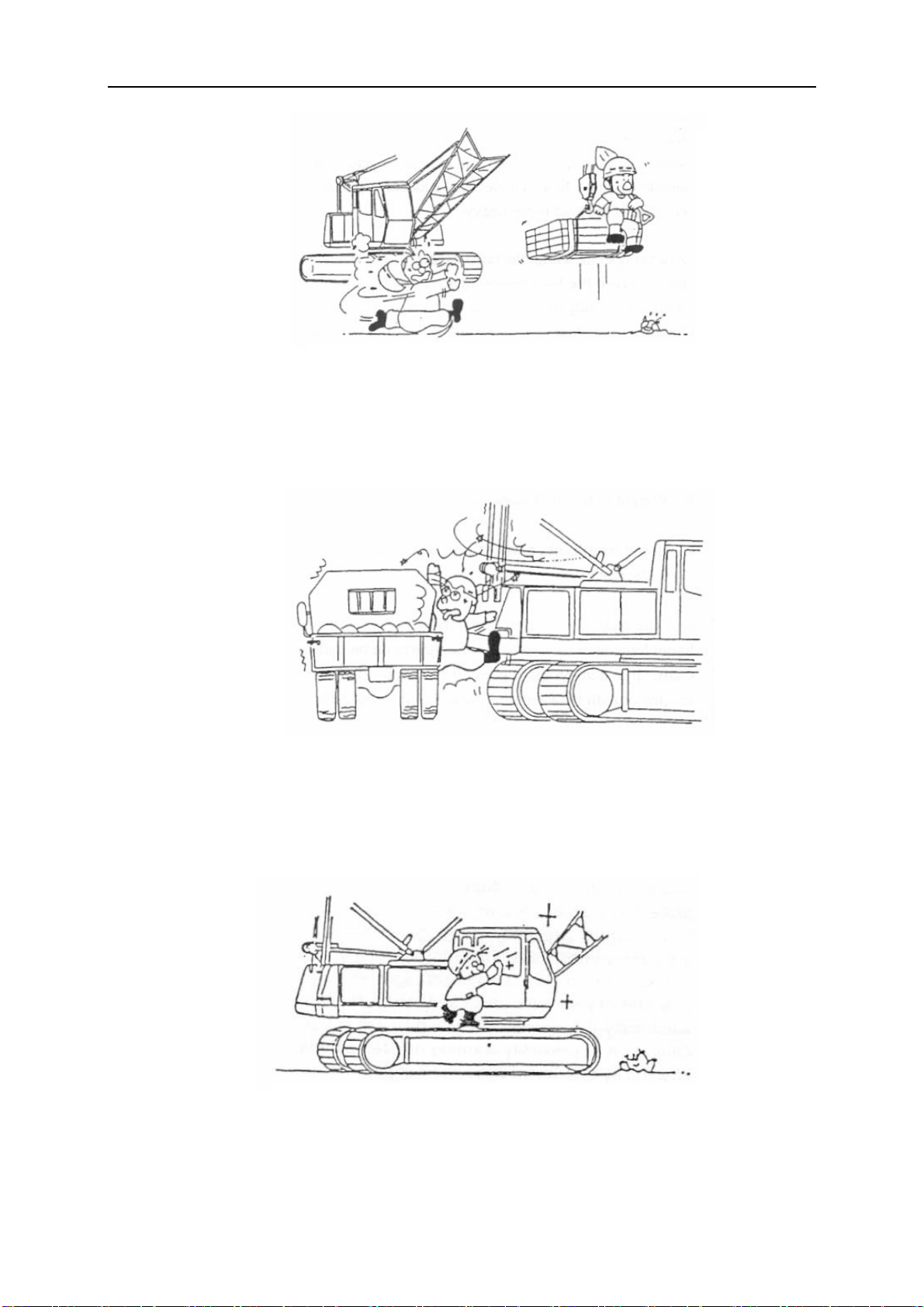
a) No person is allowed to stand under boom when crane is operated.
b) No person is allowed to stand on slewing table during operation.
c) It is forbidden to lift load over people.
eration
d) It is forbidden to lift the load when someone is standing on it.
e) Overloading operation and lifting staggered load is prohibited. Never pull load
obliquely.
Page 54

006364
0-200-03.CY
It is forbidde
f)
g) The crane can travel with a load of 70% of the rated load. In this case, the ground
should be firm and its gradient should not be more than 5/1000. The driving speed
must be less than 0.5km/h. The boom frame must be located in the driving
direction.
n to lift load hidden in the ground or frozen on the ground.
h) If the crane is operated in the vicinity of transmission systems (e.g. transmitters),
strong electromagnetic field will be generated there, so measures should be taken
to protect the crane against high frequency interference and all workers who stand
on large metal plate should wear special isolating gloves and clothes to avoid
being burnt.
aa) Prior to work near transmitter towers where an electrical charge can be induced in the
equipment or materials being handled, the transmitter shall be de-energized or tests shall be
made to determine if electrical charge is induced on the crane. The following precautions
shall be taken when necessary to dissipate induced voltages:
bb) The equipment shall be provided with an electrical ground directly to the upper rotating
structure supporting the boom; and
Page 55
006364
0-200-03.CY
cc) Ground jumper cables
when electrical charge is induced while working near energized transmitters. Crews shall be
provided with nonconductive poles having large alligator clips or other similar protection to
attach the ground cable to the load
dd) Combus tible and flammable materials shall be removed from the immediate area prior to
operations
i) The brake of hoist mechanism is not allowed to be adjusted when the crane is
lifting a load.
shall be attached to materials being handled by boom equipment
j) Under any condition, there must be three windings of wire rope left on the hoisting
drum.
k) When a load is suspending in the air, the operator is not allowed to leave the cab.
l) Operation should be carried out stably
and gently. Never operate control lever
jerkily and carry out switchover operation
abruptly.
Page 56

006364
0-200-03.CY
When actual load reaches 90%
m)
sound an alarm, to which high attention should be given.
n) Getting on and off the crane should be careful to avoid casualty.
of the rated one, the load moment limiter will
o) It is prohibited to make any modifications to the crane without permission;
otherwise you should take the consequences.
p) Stop the crane operation if one of the following conditions occurs:
1) The crane is overloaded or the weight of load is uncertain;;
2) Load’s binding or hanging is not good or load may fall due to imbalance;
Page 57
006364
0-200-03.CY
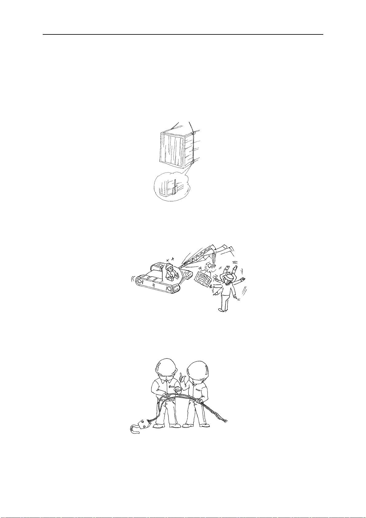
No protective mat is added betwe
3)
4) In case of poor visibility and /or darkness, it is difficult to identify load or conduct
signal;
en the edges of load and wire rope;
5) There is defect or damage of configuration or components which will impair
q) Anyone is not permitted to climb on the load
hook, slings or load.
safe operation, for example, the brake and safety equipment fail, or the wire
rope is damaged etc.
Page 58
006364
0-200-03.CY
r) Leave an ample sp
by crane counterweight due to narrow distance between counterweight and
surrounding building.
s) Keep the windows of crane operator
crane operation immediately in case of poor visibility; replace the broken window
as soon as possible.
ace for stopping crane; otherwise persons nearby may be hurt
’s cab clean to ensure good visibility; stop
t) Persons may only access and leave the crane following permission from the
crane ope
u) Keep crane clean and dry, since slippery walkway, ladder, tools or loose parts
rator and only when the crane is at a complete standstill!
Page 59

006364
may cause operator to fall down from crane.
v)
Do not lift the load which adheres to other objects forcibly. Otherwise, crane may
topple over, boom frame may buckle or objects may be damaged. Therefore, the
operator must ensure that the load is not in contact with other objects before
lifting.
w) Drive crane with great cautiousness, in working site or not. Observe the
conditions surrounding crane such as overhead power line, low-lying land, narrow
clearance, restriction to bridge and road, uneven ground and gradient of road. If
necessary, appoint a signalman to assist operator to move crane. Lock slewing
mechanism during traveling.
x) It is more dangerous that two cranes carry out lifting operations together.
Therefore, a careful calculation must be made before commencing the work, and
following import requirements for this type of operation must be observed.
1) The load is not casually attached to the crane. It must be calculated carefully
so that the actual lifting capacity of crane can not exceed the rated lifting
capacity.
0-200-03.CY
2) Ensure that each lifting tackle can bear specified load weight which is
calculated during design.
3) The crane operator, signalman and other worker must evaluate the operational
planning together before operation.
4) Ensure that crane can move properly in the whole process of operation.
y) When you leave the machine in an em ergency, you are putting your lift at risk.
Therefore, you must take following measures prior to leaving the machine.
1) Detach the load from the hook and set it down on the ground; if necessary,
lower the boom frame;
2) Apply slewing brake or lock slewing mechanism;
3) Apply parking brake;
4) Lock traveling mechanism;
5) Cut off power supply or switch off engine;
z) Do not wear loose clothing, scarves, open jackets or open shirt sleeves, and do
not wear jewellery (rings, bracelets, earrings or similar). Otherwise, there is
serious danger of injury from being pulled into moving machine parts.
Page 60

006364
0-200-03.CY
aa) Do not stop crane nea
land that may be washed down by water.
bb) Take away the key when machine remains idle. In this way, the unauthorized
person can not start the machine without permission.
cc) Unqualified person is forbidden to repair crane and change parts.
3.2.6.3.3 Preparation for crane operation
Crane operator should perform the following checks before operating the crane:
a) Check the daily record of work to ensure that all regular inspections maintenance and
repair works are performed.
b) Check the hoisting limiter, boom angle indicator, tilting-back support and other safety
equipment for functional work.
c) Check if the load-bearing parts such as wire rope (hoisting rope, derricking rope and
sling etc.), boom, outriggers, hook and load handling devices are kept in good
working order.
d) Check if there are some bolts, nuts and pins lost, and the components are cracked or
damaged.
r the bank which is possible to collapse or on low-lying
e) Ensure that no modification has been made to the crane without permission, e.g.,
increase or decrease in counterweight plate and improper repair of boom frame.
f) After starting up the engine, check if the values shown on instruments are normal.
g) Check fuel lines and hydraulic oil lines for leakage.
h) Check all control mechanisms for functional work.
i) Check brakes and clutch. Test the braking performance by lifting a load away from the
ground and suspend it in the air for a moment.
j) Keep communication between the operator and rigger.
Page 61

006364
0-200-03.CY
k) Estimate the weight and dimension
l) Crane operation can be carried out within minimum working radius. No obstacles
hinder the necessary movements. The ground at the operating site is able to support
expected loads.
m) Ensure that no obstacles are within working radius and operator can see the load
clearing from the cab. Check if the communication between operator and signalman
is kept smooth so as to ensure safe crane operation.
n) Determine the load-bearing capacity of ground to be operated upon. Ensure that
crane is supported properly and never operate the crane on the soft and uneven
surface or on the ground of high water content or covered with frozen soil. If crane is
set up close to trenches, reinforce the trenches to avoid landslide. If the ground does
not have adequate load-bearing capacity, the crane is liable to turnover. In this case,
crosstie, steel plates should be padded underneath the crawler to distribute load so
that the load-bearing capacity of the ground will not be exceeded; make sure that the
crane is leveled.
3.2.6.3.4 Notes for crane operation
a) Estimate the weight and dimensions of load to be lifted in advance.
s of load to be lifted in advance.
b) Use load handling devices (wire rope or chain) correctly. Make the vertical line of
hook pass through center of gravity of load.
c) If any part of crawler crane or load handling devices come in contact with high-voltage
line, or emergent situation occurs, the operator should stop the vehicle at once.
d) The load capacities as given in the load lifting capacity tables must be adhered to.
The loads given in the load lifting capacity tables must not be exceeded. Driving(or
slewing) too fast with a load, or setting up and loading on an uneven surface, and
swinging of suspended load should be avoided.
e) Diagonal pulling of the load to be lifted which is still in contact with the ground is
prohibited.
f) It should be avoided that the load or auxiliary lifting device collides with structural
members of crawler crane.
g) If crane gets caught in a thunderstorm during operation, following measures should
be taken at once:
-- Stop work on the crane immediately
--always set down the load and boom frame on the ground.
--apply brake or lock winch and slewing gear
--switch off the crane engine and cut off the power of load moment limiter and limit
switch
Page 62

006364
0-200-03.CY
--ask all crane workers to leave away
h) If the crane is struck by thunderbolt, following checks should be performed:
--check whether there are burnt or damaged components
--check the performance of electrical parts and load moment limiter
--check the associated components for functional work
i) If earthquake occurs when crane is operated, following measures should be taken
immediately:
-- Stop work on the crane immediately
--always set down the load and boom frame on the ground.
--apply brake or lock winch and slewing gear
--switch off the crane engine and cut off the power of load moment limiter and limit
switch
--ask all crane workers to leave away.
After earthquake, following checks should be performed prior to crane operation:
.
--check the performance of electrical parts and load moment limiter
--check the associated components for functional work
j) If any part of crawler crane or load handling device is in contact with high-voltage lines,
the best way to guarantee the personal safety of operator is to stay in operator’s cab
until the danger is obviated. If operator must leave the crane, he’d better jump rather
than climb down the cab.
k) The operator’s cab should be equipped with an emergenc y hammer which can be
used to smash the window in an emergency so that operator can run away from the
cab.
l) The load moment limiter , once be triggered, should be kept in that st ate until the crane
is not overloaded.
m) If the load moment limiter is not set to the actual configuration status of the crane, it
can not fulfill its function as a safety device.
n) Examine if the angle indicators and the strain gauges are in function.
o) The crane may topple over backwards if a load is suddenly freed since the tension
created in the boom can cause it to jerk back violently.
p) Make sure that the loads and working radius contained in the lifting capacity tables
are not exceeded.
q) When working in the vicinity of power cables, a sufficient safety clearance must be
maintained, if the cables are not isolated by electricity engineers or the hazardous
Page 63

006364
0-200-03.CY
area is not fenced off.
r) For all crane movements, the crane operator must always keep the load, as well as
the crane hook or loading equipment when the crane is not loaded, in his field of
vision. If this is not possible, the crane operator may only operate the crane according
to instructions given to him by a signalman. These instructions may be given in the
form of hand signals or over a two-way radio. Whatever method is used, precautions
must be taken to eliminate the risk of misunderstanding.
s) All employees shall be kept clear of loads about to be lifted and of suspended loads
Note:
If, despite all precautions having been taken, a flashover occurs, carry out the following
procedure:
1. Keep calm!
2. Do no
3. Warn those aroun
t leave the crane cab.
d the crane not to move and not touch the crane.
4. Move the
Not adhering to the above points may lead to risk of accidents or damage!
3.2.6.3.5 Checks after o
a) When crawler crane and auxiliary lifting device are in non-working condition, never
b) Set down the load on the ground, and if necessary low the boom frame to some
c) Shut down the engine and cut off power.
d) Check if there is leakage in someplace and repair it if necessary.
e) Clean such components as movable parts and exposed part of the piston rod of
f) Check if bolts and nuts are fitted tightly. Any defects found should be eliminated at
crane away from the danger area.
peration
park the vehicle near the embankment liable to collapse or low-lying land subject to
be washed by water.
extend; lock the slewing gear and traveling gear and apply the brake.
cylinder.
once. It is prohibited to operate the crane with fault.
g) Record the operating conditions and abnormal symptoms.
h) Check if the quantity of tools and accessories meet specified requirements.
i) Lock the operator’s cab or safety devices.
j) Take precaution measures against storm or lightning strikes.
k) Take precaution measures against frostbite in winter.
Page 64

006364
Caution:
To avoid engine from freezing in winter, drain all cooling water when park the vehicle, if no
anti-freeze is added into the cooling water
3.2.7 Electromagnetic influences
rong electromagnetic fields are likely to be present if the construction site is close to a
St
transmitter.
Caution:
0-200-03.CY
.
These
example:
1. Effect on human organs due to temperature increase.
2. Danger of burns or inflammation due to temperature increase.
3. Spark or electric arc formation.
In any case, before working with the crane ne
In addition, consult a high frequency specialist.
l) Every crane must be “totally” grounded. Check visually or with a simpler tester to ensure
m) All personnel working on the crane or with large metal objects must protect themselves
n) If one feels an increase in temperature, there is no need to panic. Always work under
o) The temperature of objects affected by high frequency radiation depends on their ‘size”.
p) Contact with other crane loads is not permitted when operating the crane (arcing). Since
electromagnetic fields can pose direct or indirect danger to persons or objects, for
ar transmitters, contact Zoomlion representative.
that ladder, cab and cable pulleys are grounded.
from burns by wearing non-conductive gloves and suitable clothing while working.
the assumption that the respective workpiece, structural steel member or support is
“hot”.
Cranes, carriers and coverings, for example, are “hooter”.
defects caused by burns considerable reduce rope carrying capacity, any such
occurrences must be reported immediately to the machinery supervisor so that the
ropes can be inspected.
q) An insulator is required at all times between the crane load hook and tackle. It is strictly
prohibited to remove this insulator.
r) The ropes may not be touched above the insulator. This is strictly prohibited!
s) Crane with attached loads may not be touched by any unprotected parts of the body
after the load has been lifted or set down.
t) Do not work with a bare upper torso or in short pants, this is prohibited.
u) To minimize absorption of high frequency radiation, large loads should be transported
horizontally if possible.
v) Loads must be grounded, or additional insulation used (rubber material between the
object and gloves) when manual work is required.
w) To avoid accidents, use a safety belt when working on components that are high off the
ground.
Page 65

006364
0-200-03.CY
x) Handlin
from the place where sparks could form due to handling of larger metal parts. Use only
conductive rubber hoses to refuel.
y) Any accidents and unexpected events must immediately be reported to the local
construction supervisor and the safety engineer.
3.2.8 Safety Signs
g explosive matter (such as refueling) may only be carried out at least 6 m away
1) Warning:
Suspended load
2) Warning:
3) Dan
Dragging/entanglement
r
ger: C
ush hazard
4) Warning:
Crushing/collisions
Page 66

006364
0-200-03.CY
5) Note: Lift
6) Warning:
point
Risk of falling
7) Danger: snagging
8) Danger: Ri
9) Prohibited: No access for
unauthorized personnel
/dragging
sk of burn
Page 67
006364
0-200-03.CY
10) Prohibited: Acce
11) W
arning: Keep off outriggers
12) Prohibited: Naked flames
ss prohibited
13) Note: First aid
14) Note: Fire extinguisher
kit
Page 68

006364
0-200-03.CY
15) No standing under the
16) Be careful in the working radius.
to the position of safety signs, please see following diagrams.
As
boom.
15
9
12
Safety signs position diagram 1
1
2 6969 2
Page 69

15
13
9
006364
0-200-03.CY
Safety signs position diagram 2
9 13
699 6 2
2
Safety signs position diagram 3
Page 70

006364
0-200-03.CY
3 4 11 16 11 4
Safety signs position diagram 4
8
12
12
6
14
7
Safety signs
position diagram 5
Page 71

Caution:
006364
0-200-03.CY
1. When the safety sign is damaged or
supplier.
2. It is forbidde
3. If the safety sign
4. The operato
to smash the window in an
n to cover or take off safety signs casually.
is covered with dust, clean it in time.
r’s cab should be equipped with an emergency hammer which can be used
emergency so that operator can run away from the cab.
illegible, please order it from appointed service
Page 72
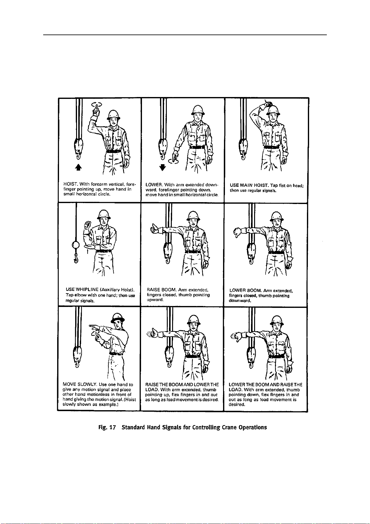
006364
3.2.9 Hand Signals for Controlling Crane Operations
0-200-03.CY
Page 73

006364
0-200-03.CY
Page 74

006364
0-200-03.CY
Caution:
1. We
2. Hand signals must fir
3. In any case, national traf
recommend using the hand signals illustrated above. However, users can decide
on their own
regions may diff
Misunderstand of hand signals may lead to serious accidents.
hand signals depending on actual condition, as different countries and
er in the expression of hand signals.
st be discussed and mutually agreed upon and clearly executed.
fic regulations must always be observed when abroad.
Page 75

Chapter 4
Crane operation
Page 76
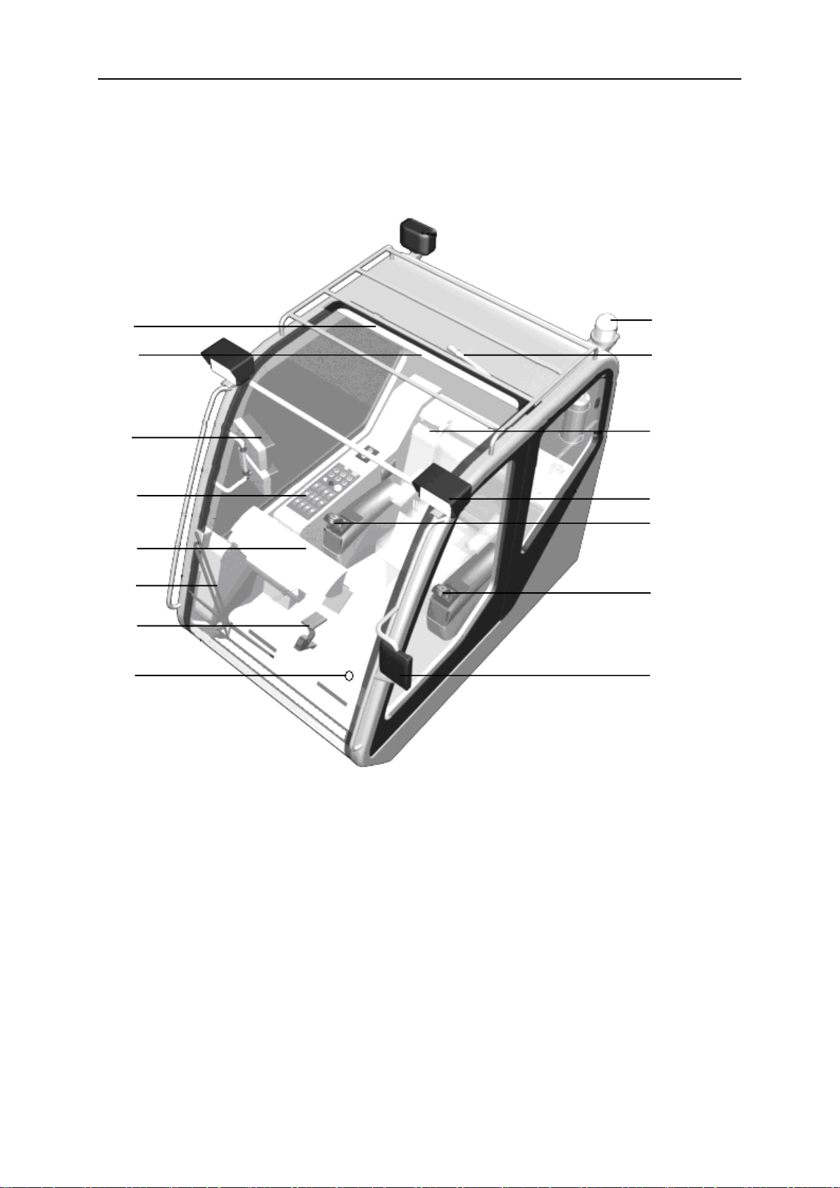
0066340-200-04Y.C
1
2
3
4
5
6
7
8
10
11
12
15
14
9
13
4.1 Operating and control instruments
4.1.1 Overview of crane operator’s cab
Overview of crane operator’s cab
Page 77

0066340-200-04Y.C
No.
Description
Position and function
1
Fan
At the rear right side of operator’s cab
2
Interior light
On the top of operator’s cab
3
Monitor
Display the images from the video camera near the slewing
table
4
Right control panel
The rocker switches, rotary switches and ignition starter
switch are fitted on the control panel. (For details, see
Section 4.1.4 and 4.5)
5
Digital display
system
Consists of display of load moment limiter and display of
control system
(For details, see Section 4.2)
6
Front windshield
wiper
At the bottom of front windshield
7
Accelerator pedal
Control the engine speed
8
Foot-operated
switch
Actuate the horn
9
Rearview mirror
At front left side of operator’s cab
10
Control box, left
Control the motions of hoisting winch 2, slewing mechanism
and left crawler. (For details, see Section 4.1.2 and 4.5)
11
Control box, right
Control the motions of hoisting winch 1, derricking
mechanism, right crawler and self-assembly & dismantling
mechanism. (For details, see Section 4.1.3 and 4.5)
12
Working floodlights
Two working floodlights, front;
One working floodlight, rear
13
CD player
14
Roof windshield
wiper
At the roof of operator’s cab
15
Warning light
At the rear left side of operator’s cab
Components in crane operator’s cab
Page 78

4.1.2 Left control box
No.
Names of the components
Remarks
16
Emergency stop button
For details, please refer to section 4.4.1
17
Left control lever
18
Deadman’s button
19
High-speed switch
Control the high speed of slewing movement. For
details, please refer to section 4.5.4.
20
“Swing free running” switch
For details, please refer to section 4.5.4.3
21
Symbol “reel off H2”
H2 refers to hoisting winch 2
22
Symbol “spool up H2”
H2 refers to hoisting winch 2
23
Symbol “left crawler forwards”
24
Symbol “left crawler
backwards”
25
Symbol “slew to the left”
26
Symbol “slew to the right”
20
17
18
19
23
21
16
25
22
26
24
0066340-200-04Y.C
Components of left control box
Page 79

0066340-200-04Y.C
(1) The crane movements can be carried out only when deadman’s button is pressed.
(2) The crane movements can still be carried out before the control lever is returned to
neutral position with deadman’s button released. However, to perform the next
crane movement after returning the control lever to neutral position, the operator
must press deadman’s button first and then move the control lever. Otherwise, the
operation of control lever is invalid.
(3) In normal condition, stop the crane movements by returning the control lever to
neutral position.
(4) Make sure that the emergency stop button is triggered when needing to connect
the power or start up the engine again.
Page 80

4.1.3 Right control box
No.
Names of the
components
Remarks
27
Right control lever
28
Deadman’s button
29
Switch
Not assigned
30
High-speed switch
Control the high speed of hoisting winch1, hoisting winch 2,
luffing jib derricking winch and travel gear. For details, please
refer to section 4.5.
31
Symbol “extend
mounting cylinder on
A-frame”
Reserved
32
Symbol “retract
mounting cylinder on
A-frame”
Reserved
33
Symbol “reel off H1”
H1 refers to hoisting winch 1
34
Symbol “spool up
H1”
H1 refers to hoisting winch 1
35
Symbol “right crawler
forwards”
36
Symbol “right crawler
backwards”
30
27
28
29
32
34
35
38
36
31
33
37
0066340-200-04Y.C
Components of right control box
Page 81

0066340-200-04Y.C
37
Symbol “spool up
E/W1”
E refers to derricking winch, and W1 refers to luffing jib
derricking winch (spare)
38
Symbol “reel off
E/W1”
E refers to derricking winch, and W1 refers to luffing jib
derricking winch(spare)
(1) The crane movements can be carried out only when deadman’s button is pressed.
(2) The crane movements can still be carried out before the control lever is returned to
neutral position with deadman’s button released. However, to perform the next
crane movement after returning the control lever to neutral position, the operator
must press deadman’s button first and then move the control lever. Otherwise, the
operation of control lever is invalid.
(3) In normal condition, stop the crane movements by returning the control lever to
neutral position.
Page 82

4.1.4 Control panel assy.
No.
Names of the
rocker switches
The key
Remarks
39
Master lighting
switch
1st position: The LED on the switches of control
panel lights up;
2nd position: master lighting switch
40
“Working floodlight”
switch
Control all the working floodlights on the crane
41
“Cold-start on/off”
switch
Control the cold-start of the engine
42
Controller power
supply switch
Control the power supply of PLC controller and
LCD screen
39
40
41
42
47
48
49
50
45
46
43
44
0066340-200-04Y.C
Rocker switches on the control panel
Description of the rocker switches
Page 83

0066340-200-04Y.C
No.
Names of the
rocker switches
The key
Remarks
43
“Front windshield
wiper” switch
Control the front windshield wiper
44
“Low-speed” switch
For details, please refer to section 4.5
45
“Automatic
lubrication system”
switch
Lubricate the superstructure lubricating points
automatically.
46
“Front windshield
washer” switch
Control the front windshield washer
47
“Oil cooling fan”
switch
Pressing this switch can cool the hydraulic oil
48
“Engine shutdown”
switch
Pressing this switch can shut down the engine
Press the “engine shutdown” switch and hold it
for more than 30 seconds, the working hours of
the engine can be saved. In normal situation,
using the ignition key switch to stop the engine
is prohibited.
Ensure that this switch is not pressed down
before engine startup. Otherwise, the crane
cannot be started.
49
“SETUP” switch
For details, please refer to section 4.4
50
“Travel” switch
To carry out traveling movements, the operator
must first press the traveling switch and then
operate control lever!
Do not press this switch when crane winch is
operated.
(1) Put the master lighting switch on the 2nd position before switching on the
working floodlight switch .
Page 84

0066340-200-04Y.C
(2) After putting the master lighting switch on the 2nd position, the LED on the
rocker switches of control panel is still on.
(3) Press the “engine shutdown” switch and hold it for more than 30 seconds, the
working hours of the engine can be saved. In normal situation, using the ignition
key switch to stop the engine is prohibited.
Page 85

0066340-200-04Y.C
51
54
52
53
57
55
56
58
59
60
61
62
63
64
Right control panel
Page 86

0066340-200-04Y.C
No.
Names of the
components
Remarks
51
“H2 Control” Switch
Turn the switch to left, hoisting winch 2 (H2 )will not work;
Turn the switch to right, hoisting winch 2(H2 ) can work.
52
“Manual/automatic
accelerator” switch
When the switch is set in neutral position, the engine speed is
controlled by accelerator pedal.
When the switch is set in “manual” position, the engine speed
is controlled by Manual ACCEL adjuster.
When the switch is set in “automatic” position, the current
Manual ACCEL adjuster value is the maximum adjustable
speed of engine.
53
“H1Control” Switch
Turn the switch to left, hoisting winch 1(H1) will not work;
Turn the switch to right, hoisting winch 1(H1) can work.
54
“Hoisting bypass”
switch
For details, please refer to section 4.4.
55
“Lowering bypass”
switch
For details, please refer to section 4.4.
56
“Derricking bypass”
switch
For details, please refer to section 4.4.
57
“A-frame
erecting/lowering”
switch
Turn the switch to left, A-frame will be erected;
Turn the switch to right, A-frame will be lowered.
58
“Tilt cab forwards
/backwards” switch
Turn the switch to left, the cab will tilt forwards;
Turn the switch to right, the cab will tilt backwards.
59
“W1 winch/Assembly”
switch
When the switch is turned to “W1” position, move right control
lever to left and right to control the luffing jib derricking winch
(W1). This is only available for W1 winch. (For details, see
section 4.5.2.2.3.3.)
When the switch is turned to “Assembly” position, push right
control lever forwards and backwards to control the mounting
cylinder on A-frame. This is only used during assembly and
dismantling operation. (For details, see section 4.5.9.)
60
“Synchronization”
switch
“Synchronization” switch includes “Reeve sync” position and
“Mast +E sync” position.
“Reeve sync” For detailed description of “Mast +E sync”, For
details, please refer to section 4.5.3.
61
“Reeving winch”
switch
Turn the switch to left, the reeving winch will be spooled up;
Turn the switch to right, the reeving winch will be reeled off.
Components on right control panel
Page 87

0066340-200-04Y.C
No.
Names of the
components
Remarks
start.
1. When the switch is placed in “off” position, the power
supply of the crane is turned off.
2. When the switch is placed in “power” position, the power
supply of the crane is turned on, including the control
system, auxiliary control system and engine electrical
control system.
3. When the switch is placed in “start” position, the starting
motor of the engine is turned on, thus starting the engine.
Releasing the switch after the crane starts up, the switch
will return to “power” position automatically.
64
“Manual ACCEL
adjuster” switch
1. In “manual accelerator mode”, the adjuster is used to
control the engine speed. Turn it clockwise to the required
speed.
2. In “auto accelerator mode”, the current value is the
maximum adjustable speed of engine.
(1) In cold weather, the engine will be preheated automatically after startup. Therefore,
the delay of engine startup in cold weather is a normal phenomenon.
(2) “Assembly” position of “W1 winch / Assembly” selective switch is only used for
assembling and dismantling.
(3) Only when the crane is fitted with luffing jib derricking winch (W1), can the
operator can turn the “W1 winch / Assembly” selective switch to “W1 winch”
position. Otherwise, there is a risk of danger!
(4) When the “Manual/automatic accelerator” switch is set in “manual” position
before starting the engine, turn “Manual ACCEL adjuster” to “MIN” position or
place “Manual/automatic accelerator” switch to the neutral position.
It’s dangerous to use “hoisting bypass” and “lowering bypass” switches, which can’t
be used in normal situation. Under special circumstances, and the user knows the
possible consequences, then he can operate it very carefully.
Page 88

0066340-200-04Y.C
No.
Description
Function
65
Display of load
moment limiter
Display the current working condition of crane
66
Display of control
system
Display the information about crane control system
65
66
4.2 Instruction for digital display system
Digital display system
4.2.1 Load moment limiter
As to detailed operation, refer to Load Moment Limiter Operating Manual.
4.2.2 Display of control system
It can display the working state of crawler crane in real time. When abnormal conditions occur,
the warning light will flash or a prompt will appear on the screen. The display can show the
working mode, engine speed, wind speed, voltage, water temperature, oil level, load and
pressure of pumps etc.
Page 89

0066340-200-04Y.C
Main screen of display
The main screen is subdivided into five main areas.
a) Engine information
b) Alarm functions
c) Monitored additional functions
d) Pressure of crane control pumps
e) Function key line
Note: In view of legibility, Figures of display of control system given here are amplified.
However, when crane is working, the screen shown on the display is not as
large as the figure.
Page 90
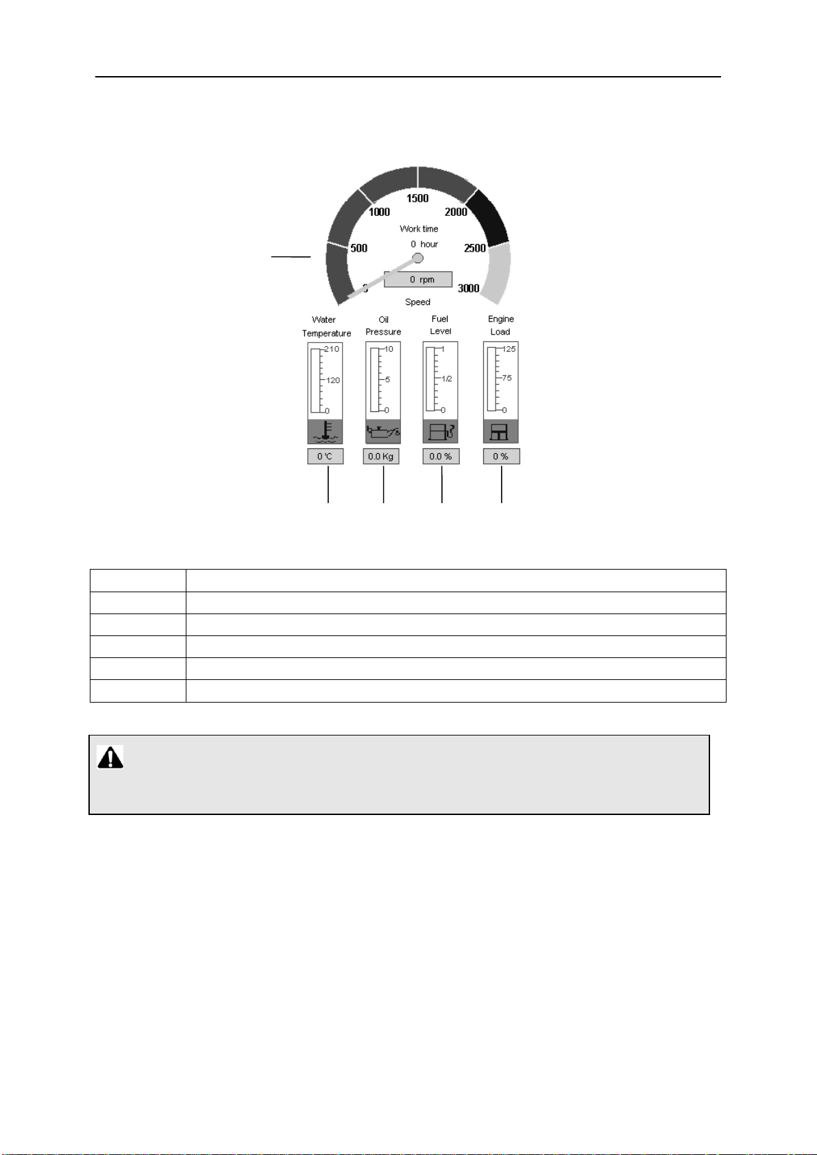
4.2.2.1 Engine information
No.
Description
67
Engine speed and working time
68
Water temperature
69
Engine oil pressure
70
Fuel level
71
Engine load
67
68
69
70
71
0066340-200-04Y.C
Display of engine information
Note:
The fuel leveland engine load are shown in percentage.
Page 91

0066340-200-04Y.C
No.
Description
Function
72
Icon “Engine oil pressure”
When engine oil pressure is too high, the icon
will flash.
73
Icon “Water temperature”
When water temperature reaches the specified
value, the icon will flash.
74
Icon “Preheating”
When engine is being preheated, the icon
will flash.
75
Icon “Air filter clog”
When air filter is clogged, the icon will
flash.
76
Icon “Oil inlet /return pipe
clog”
When oil inlet pipe or oil return pipe is clogged,
the icon will flash.
77
Icon “Upper limit switch on
H1”
When load hook 1 comes into contact with the
hoisting limit switch weight during its upward
movement, the icon will flash.
78
Icon “Lower limit switch on
H1”
When there are only three windings of wire rope
left on H1, the icon will flash.
79
Icon “Upper limit switch on
H2”
When load hook 2 comes into contact with the
hoisting limit switch weight during its upward
movement, the icon will flash.
80
Icon “Lower limit switch on
H2”
When there are only three windings of wire rope
left on H2, the icon will flash.
81
Icon “main boom,
85°”
When main boom angle reaches 85o, the icon
will flash.
72 73 74 75 76
77 78 79 80 81
4.2.2.2 Alarm functions
Display of alarm function
The limit ranges of the working state of crane are monitored. The following icons will flash
when the limits are reached.
Page 92

0066340-200-04Y.C
No.
Description
Function
82
Crane inclination
Display the inclination of crane to the horizontal in longitudinal
and lateral direction
Note: The traveling direction of crane is taken as positive
direction.
83
Wind speed
Display the current wind speed at boom head detected by
anemometer
84
Voltage of machine
Display the voltage of machine battery
87
86
85
88
89
90
82
83
84
4.2.2.3 Monitored additional functions
Display of monitored additional functions
4.2.2.4 Pressure of crane control pumps
Page 93

0066340-200-04Y.C
No.
Description
85
Pressure in main pump I circuit
86
Pressure in main pump II circuit
87
Pressure of A-frame erection cylinder (left)
88
Pressure in slewing pump circuit
89
Pressure in control pump circuit
90
Pressure of A-frame erection cylinder (right)
No.
Description
91
Pressure of tilting-back support cylinder for WA-frame 1 (left)
92
Pressure of tilting-back support cylinder for WA-frame 1 (right)
No.
Description
Operation and function
93
Key “main screen”
Pressing this key in any other screen can switch to “main
screen” directly. The main screen is shown in Section 4.2.2.
94
Key “IO”
Press this key to enter into “I/O screen”. In this screen, all the
input/output points of PLC can be checked for correction.
95
Key “Parameter
adjustment”
Adjust relevant parameters of main motions
96
Key “Fault diagnosis”
At present, this function is not set in the control system of
crane.
97
Key “working
conditions”
Pressing this key can switch to “Working conditions screen”.
Under this screen, the working conditions for main crane
movements can be checked.
98
Page up
99
Page down
100
Key “Enter”
Confirm the previous operation or save the modified
parameters.
91
92
93 94 95 96 97 98 99 100
Display of pressure of crane pumps
Display of pressure of tilting-back support cylinder for WA-frame 1
4.2.2.5 Function key line
Function key line
Caution:
Never adjust the parameters without the permission of our technicians.
Page 94

0066340-200-04Y.C
4.3 Startup of crane
4.3.1 Adjustment of crane operator’s seat
a) Vertical adjustment of headrest
The height of headrest is adjusted manually.
b) Adjustment of armrest
c) Horizontal adjustment of seat
The height of armrest can be adjusted by adjusting
knobs.
-- Pull the lever upwards;
-- Move the seat to required position;
-- Release the lever.
Page 95
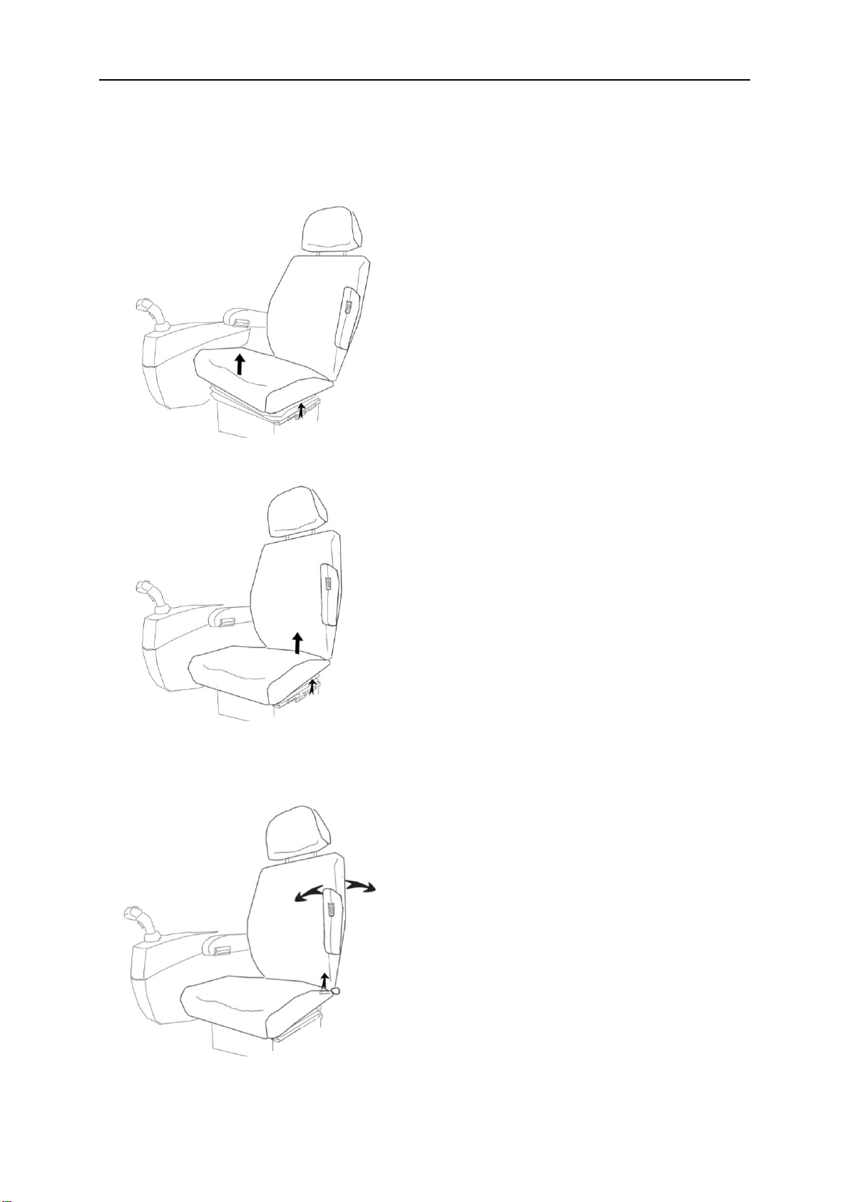
0066340-200-04Y.C
d) Adjustment of the height of seat
There are two levers to adjust the height of the seat. The front lever adjusts the height of
the front of the seat, and the rear lever adjusts the height of the rear of the seat.
-- Pull the lever upwards, the front of the
seat is raised up.
-- Pull the lever upwards, the rear of the
seat is raised up.
e) Adjustment of backrest
-- Press your back gently against the backrest;
-- Pull the lever upwards;
-- The backrest tilts backwards.
-- pull the lever downwards.
-- The backrest automatically tilts forwards.
Page 96
0066340-200-04Y.C
Danger:
Never check the coolant level before the engine is cooled down. Otherwise, you
may get scalded.
Danger:
Before carrying out any boom movements, make sure that there are no loose parts
on the boom such as pin, retaining spring or ice. Otherwise, the falling parts may hit
the persons or other objects.
4.3.2 Checks before startup
Following checks should be performed before startup of engine.
a) Check oil filter and oil level
1) Engine oil level;
2) Oil level of hydraulic oil tank;
3) Oil filter on hydraulic oil tank.
b) Check coolant level
Add coolant to the rim of oil filler.
c) Check the general conditions of crane
Before starting up the crane, the operator must ensure that the following conditions are
fulfilled:
1) The crane is horizontally aligned;
2) The toothed gear of slewing ring must be clean and greased;
3) The air inlet of oil cooler is not blocked;
4) All cowlings and covers on the sides must be closed and locked;
5) No person or object is within the slewing radius of crane;
6) No ice or snow is on the wire rope, winding drum and limit switches;
7) There are no loose parts on the slewing table or on the boom;
8) The shutoff valve on the hydraulic oil tank should be opened;
9) The fixing pin for slewing table is pulled out.
Page 97

0066340-200-04Y.C
Engine oil
pressure
Inclinometer,
anemometer, voltage
Fuel level
4.3.3 Turn on power supply
Insert ignition key into ignition lock and turn it clockwise to the 1st position, then the power
supply is turned on.
Turn on power supply
a) Digital display system
After the power supply is turned on, press the controller power supply switch on the
right control panel, the LCD screen of load moment limiter and LCD screen of control
system are started.
Check the following indicators and warning icons:
1)
2) Icon “Fuel level”;
3) Icon “Air filter clog” ( );
4) Inclinometer;
5) Anemometer;
6) Voltage;
Page 98

0066340-200-04Y.C
(1) Correctly set current work mode on load moment limiter, otherwise, operation
is not permitted to be carried out.
(2) Low engine oil pressure will impair the working efficiency of engine.
(3) Add diesel oil in time if the oil level is too low.
(4) If air filter is clogged, the icon “air filter clog” will flash. At this moment,
clean or change air filter.
(5) The inclination range for the superstructure: the inclination should be less
than 1% in both lateral direction and longitudinal direction. If this range is
exceeded, the crane operator must adjust the crane to horizontal position
firstly.
(6) The maximum in-service wind speed should not exceed 9.8m/s.
(7) The maximum out-of-service wind speed should not exceed 21m/s when the
crane is only fitted with main boom;
The maximum out-of-service wind speed should not exceed 15m/s when the
crane is fitted with main boom and fixed jib.
If wind speed reaches or exceeds these values, the entire boom should be
lowered down.
(8) The battery master switch must be switched on to electrify the machine.
(9) To protect the battery, switch off the battery master switch if the crane will not
work for a long time.
b) Right control panel
1) Illumination
Press the “interior light” switch, the interior light in the cab will light up.
Turn the master lighting switch to the 1st position or the 2nd position, the LED
on the switches of the control panel will light up;
2)
Turn on front windshield wiper and roof windshield wiper by pressing the front
windshield wiper switch and roof windshield wiper switch respectively.
Page 99
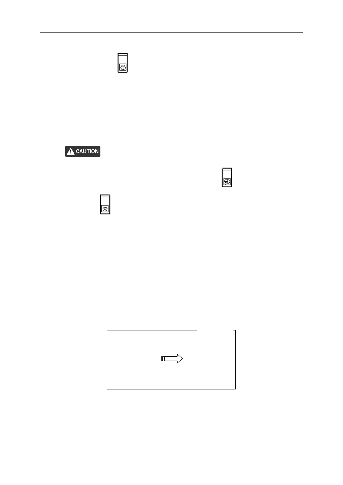
0066340-200-04Y.C
Start the engine
When front windshield needs to be washed, please press the “front windshield
washer” switch
3) Fan
There is a fan fitted on the rear right side of the operator’s cab. Turn on the switch on
it, the fan will run.
4) Horn
Check if the horn is working properly with foot-operated switch before work.
(1) Before switching on the working floodlight switch , put the master lighting
switch on the 2nd position.
(2) Warning light on boom head is a kind of solar light. The warning light is
charged during the day and will flash at night.
(3) The horn must be actuated before starting the engine to warn the person in the
vicinity of the crane.
(4) The horn can only be actuated before starting the engine and in emergencies.
4.3.4 Start engine
Insert the ignition key into the ignition lock and turn it clockwise to the 2nd position, then the
engine is started.
Start the engine
Page 100

0066340-200-04Y.C
(1) When ambient temperature is higher than or equal to﹣10℃, the engine will be
preheated automatically before startup. Therefore, the delay of engine startup in
cold climate is a normal phenomenon.
(2) When the engine is being preheated, the icon will flash. After the engine is
preheated, it will go out.
(3) When ambient temperature is lower than﹣10℃, the operator must actuate engine
cold-start device first and then start the engine. When engine cold-start device is
actuated, put the controller power (if there is) in (stop) position, the ignition key
switch in (power) position, the cold-start rocker switch in the 2nd position.
After running the cold-start device for about ten minutes, start the engine.
What’s more, if the water temperature of the engine in cold climate is too low, start
the cold-start device to improve the water temperature, ensuring that the water
temperature of the engine is in normal range.
(4) The engine can not work with full load until the running temperature is reached.
4.4 Safety devices
The crane operator must check all safety devices for functional work before every crane
operation.
Operating crane with faulty safety devices is prohibited!
4.4.1 Emergency stop button
As soon as this emergency stop button is pressed,
– the electrical control system is switched off and the diesel engine shuts down;
– All crane movements stop immediately.
The emergency shut-down button must only be used in case of emergency and not as
a normal procedure for shutting down the diesel engine!
If an emergency stop is triggered while a load is being lifted, there may be a risk of
accident owing to swinging of load.
 Loading...