

Page 1

ane
QUY260CR/F32Y
ZOOMLION ® Crawler Cr
QUY260CR/32Y
Page 2

Page 3

Contents
1 Complete Vehicle .................................................................................... 0066340-200-01-32Y
2 Boom System .......................................................................................... 0066340-200-02-32Y
3 Power System .......................................................................................... 0066340-200-03-32Y
4 Slewing Table System ............................................................................. 0066340-200-04-32Y
5 Undercarriage System ............................................................................ 0066340-200-05-32Y
6 Outer Parts ................................................................................................. 0066340-200-06-32Y
Page 4

Page 5

Foreword
Thank you for purchasing our product. We will try our best to provide you with satisfactory and
excellent service.
ZOOMLION crawler crane is a product integrating our many years' experience and advanced
technologies. This catalog introduces the structure and assembling features of spare parts as well
as the outer parts required in the main systems.
Carefully reading this spare parts catalog will save your repair and ordering time.
Using this spare parts catalog:
l makes it easier to become familiar with the crane
l avoids problems due to improper assembly and dismantling
l extends the service life of your crane
l reduces repair cost and downtime
1. How to use this catalog
(1) This spare parts catalog includes 6 chapters: complete vehicle, boom system, power
system, slewing table, undercarriage and outer parts. The chapter summary at the
beginning of the catalog provides a quick overview and the table of contents at every
beginning of the chapter shows how the individual chapter is structured;
(2) This catalog also covers the description of main outer parts which are individually sorted
in chapter “outer parts”; and those outer parts with detailed information are highlighted in
grey in the texts;
(3) How to find the marked information of the spare parts you needed. First you should find
out in which chapter the information of the required spare parts is described by looking for
the chapter summary, and then glance through the table of contents at the beginning of
the desired chapter;
(4) Flick through the pages until the page numbers of the spare part are found. And the spare
parts code, description, specification and quantity can be referred in the text.
2. Relevant instructions
(1) The number and description in the top right-hand corner of the text / picture indicate the
component page number and chapter’s name. The component page number consists of
code no. and picture / text page number. For detailed information, refer to examples 1 and
2;
Example 1:
We code hydraulic tank “300”. If the hydraulic tank offers 2 pictures and 1 text, its first
picture page number is coded into “300-1”, second picture page number “300-2” and first
text page number “300-3”.
Example 2:
We code “Main boom pivot section” (secondary component) into“010020”, so its first page
number is coded into “010020-1” and second page number “010020-2”.
(2) We have sorted all purchased spare parts in our method. For detailed information, refer to
example 3;
Example 3:
If we code one purchased engine “1000000025” and use its first 5 figures as its
abbreviation, its first page number is coded into “10000-1”.
(3) We have coded our suppliers (stamped on the parts), and you can refer to the page number
according to the supplier code in the contents to find out the information of purchased spare
Page 6

parts needed;
(4) The catalog is made up of individual, serially numbered chapters. And the page number is
located in the bottom middle part of each page. You can look through this catalog according
to these page numbers.
Declaration
Our products and technical documents are subject to technical improvements and changes
without notice. Therefore, please acquaint yourself with our updated technology information. If
there are differences between illustration and product, refer to the product.
Page 7

Chapter 1
Complete vehicle
Page 8
QUY260CR CRAWLER CRANE
D00663400002000000Y
1-1
Page 9

QUY260CR CRAWLER CRANE
D00663400002000000Y
POS. ITEM DESCRIPTION & SPECIFICATION QTY.
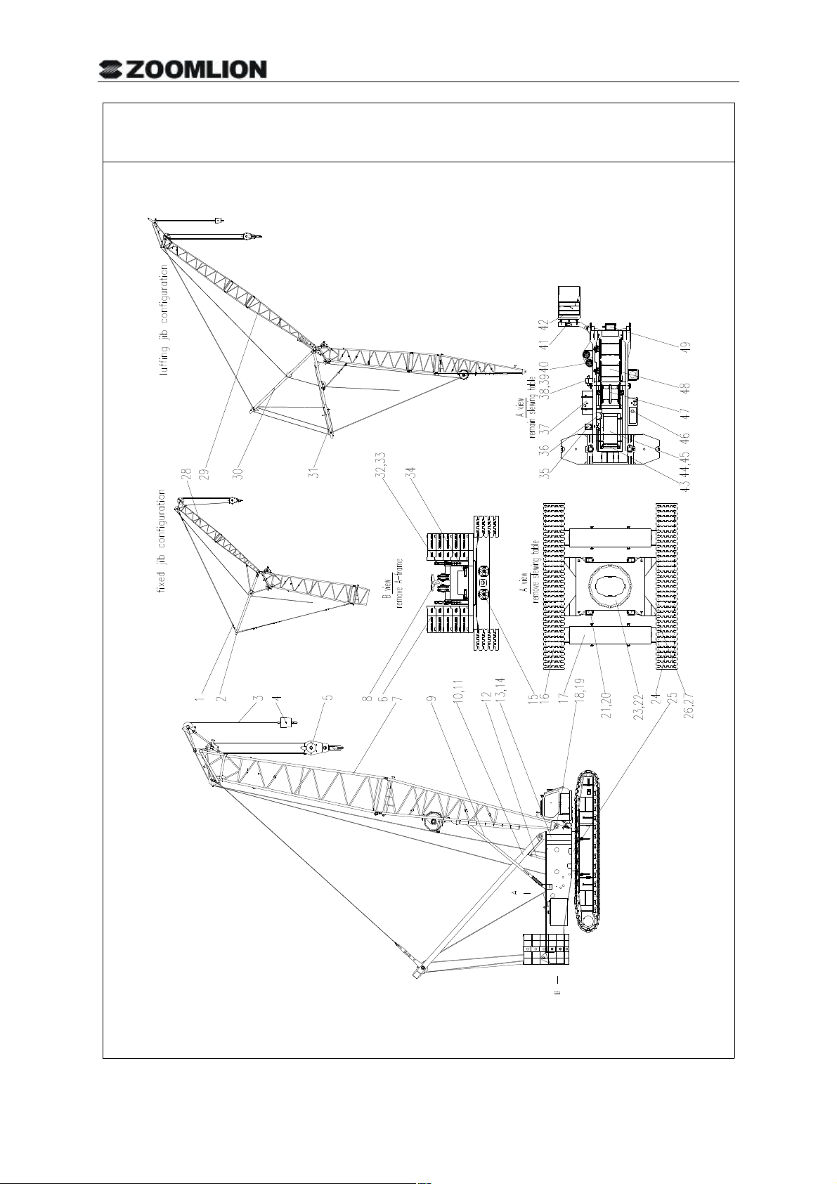
1 00663405400000001 Anchoring rods assy. 1
2 00663307800000002 FA-frame 1
3 00663408200000000 Wire rope 2
4 00663404200000001 Auxiliary load hook 1
5 00663404100000001 Main load hook 1
6 00663400610000000 Counterweight 2
7 006634001 00000 Main boom assy. 1
00 2
8 00663302100000002 Derricking crown block 1
9 0066340310 00000 Tilting-back support assy. 4
10
10 00663401800000000 A–frame assy. 1
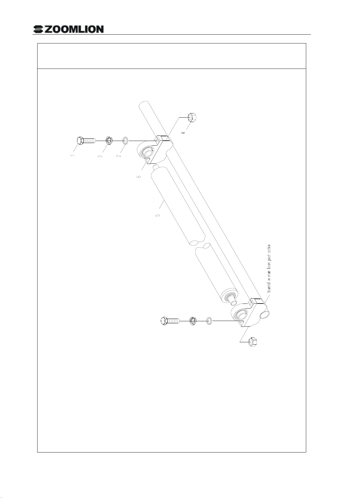
11 00663403600000001 Mounting cylinder 1
12 1010200089 A–frame erection cylinder SYG140/110-1900A 1
13 00663400400000001 Slewing table 1
14 00663404600000001 Slewing table attachments 1
15 00663400800000000 Support plate assembly 1
16 006634024000000 Left crawler carrier assy. 1
04
17 1090900007 Central counterweight QUY-95-14 1
18 00663305300000000 Boom pivot section bolting cylinder 1
19 00663404700000001 Structural member assembly 4
20 00663405800000000 Folding bracket 4
21 00663302200000000 Support cylinder 1
22 00663402800000001 Undercarriage central section 1
23 00663401700000001 Pipe layout – undercarriage hydraulic system 1
24 006634025000000 Right crawler carrier assy. 1
04
25 00663404500000000 Slewing ring assembly 1
26 00663409600000000 Crawler carrier assembly 1
27 00663303200000000 Crawler carrier bolting cylinder 1
28 00663300200000001 Fixed jib 1
29 006634066 00000 Luffing jib 2
30 006634080 00000 WA-frame 1 1
31 006634079 00000 WA-frame 2 1
00 2
00 2
00 2
32 00663404910000000 Counterweight assembly 1
33 1010200006 Counterweight lifting cylinder PY1340-340000-0001 1
34 00663307100000001 Counterweight bolting cylinder 1
35 00663301210000000 Exhaust system 1
1-2
Page 10

QUY260CR CRAWLER CRANE
D00663400002000000Y
POS. ITEM DESCRIPTION & SPECIFICATION QTY.
36 00663301410000001 Air intake system 1
37 00663401110000000 Fuel system of Cummins engine 1
38 00663404800000000 Hydraulic elements assembly 1
39 00663401600000001 Pipe layout – superstructure hydraulic system 1
40 00663304400000003 Slewing mechanism 1
41 1010200003 Operator’s cab tilting cylinder SYG63/45-170 1
42 00663400700000001 Operator’s cab assembly 1
43 00663301310000000 Cooling system 1
44 00663301010000000 Engine and suspension system 1
45 00663203900000000 Oil pump drive device 1
46 00663403000000000 Hydraulic tank 1
47 00663402000000001 Derricking mechanism 1
48 00663403500000002 Hoisting mechanism 2
49 00663408300000000 Reeving winch 1
50 00663405900000000 Pipe layout – central lubricating system 1
51 006633076 00000 Air conditioning 1
00 2
52 00663400000001010 Painting drawing for QUY260 crawler crane 1
53 00663407000000000 Instruction board assembly 1
54 00663405100000001 Cummins engine housing assembly 1
55 00663400500000002 Boarding assembly 1
56 00663401510000000 Hydraulic system diagram 1
56 00663401500000001 Hydraulic system diagram 1
57 00663405600000002 Load moment limiter assembly 4
58 006633061 0000000 Superstructure electrics 1
59 006633062 00000 Operator’s cab electrics 1
60 006633063 0000000 Slewing table electrics 1
61 006634064 00000 Boom electrics 2
4
00 2
4
01 1
62 00663409100000000 Attached tools 1
63 00663409200000001 Attached spare parts list 1
64 00663301900000002 A – frame erection mechanism assembly 1
65 00663409900000000 Technical documents 1
66 204060026 10 # aviation hydraulic oil SH 0358-1995 1
66 204060004 Hydraulic oil H68 NUTO 1
66 204060001 Hydraulic oil H32 NUTO 1
66 204060000 Hydraulic oil H46 NUTO 1
1-3
Page 11

QUY260CR CRAWLER CRANE
D00663400002000000Y
POS. ITEM DESCRIPTION & SPECIFICATION QTY.
67 00663408500000000
68 00663408600000000 Pipe layout - hydraulic circuit of slewing mechanism 1
69 00663408700000000 Pipe layout - hydraulic circuit of auxiliary devices 1
70 00663408800000000 Pipe layout - boom hydraulic circuit 1
71 00663409700000000 Technical requirements for package and transportation 1
72 00663406900000002 Boom section assy. 1
73 00663200900000000 Intercooling system 1
74 00663400300000000 Heavy fixed jib assy. 1
75 00663405000000000 Electric assembly 1
76 00663408910000000 Hydraulic pipe assy. of Rexroth system 1
Pipe layout - hydraulic circuit of winches in the slewing
table
1
1-4
Page 12

1-5
Page 13

Chapter 2
Boom system
Page 14

Page 15

Chapter 2 Boom system
1 Main boom assy. D00663400 0000001Y ................................................................................ 2-1
1.1 Main boom head assy. D00663400 040000 Y .................................................................... 2-3
1.2 Main boom head attachments assembly D00663300102600001Y ........................................ 2-7
1.3 Main boom pivot section attachments assembly D00663400102400001Y ............................ 2-9
1.4 Main boom pivot section attachments assembly D00663400112400001Y .......................... 2-11
1.4.1 Rope support D00663300102000000Y ............................................................................ 2-13
1.5 Angle indicator D00663300102200000Y .............................................................................. 2-15
1.6 Tip boom assy. D00663400100800001Y .............................................................................. 2-17
1.7 3m main boom intermediate section attachments assembly D00663300102800001Y .. 2-19
1.8 6m main boom intermediate section attachments assembly D00663300103000001Y ....... 2-21
1.9 9m main boom intermediate section attachments assembly D00663300103200001Y ....... 2-23
1.10 Luffing jib derricking winch D00663402000400002Y ......................................................... 2-25
1.11 260t load hook D00663404100000001Y............................................................................. 2-27
1.12 160/100t load hook D00663404200200002Y ..................................................................... 2-29
1.13 50t load hook D00663404200400002Y ............................................................................. 2-31
12
012
1.14 30t load hook D00663304200600002Y ............................................................................. 2-35
1.15 16t load hook D00663804200800000Y .............................................................................. 2-37
1.16 Main boom tilting-back support D00663303100200000Y ............................................... 2-39
1.17 Main boom anchoring rods D00663405400200001Y ....................................................... 2-41
1.18 Light anchoring rods D00663405401000001Y ................................................................ 2-43
1.19 Intermediate tensioners on light duty boom D00663405401200001Y ............................ 2-45
2 Fixed jib D00663300200000001Y .......................................................................................... 2-47
2.1 Fixed jib head D00663300200600002Y .............................................................................. 2-49
2.2 Front anchoring rods of fixed jib D00663305400600000Y ................................................. 2-51
2.3 Rear anchoring rods of fixed jib D00663405400400001Y .................................................. 2-53
2.4 FA-frame D00663307800000002Y ..................................................................................... 2-55
2.5 Front tilting-back support of fixed jib D00663303100600000Y ......................................... 2-57
2.6 Rear tilting-back support of fixed jib D00663303100400000Y ............................................. 2-59
2.7 Fixed jib front anchoring rods (crane used to lift tunnel boring machine)……………………
D00663405411000000Y ................................................................................................................. 2-61
2.8 Heavy fixed jib D00663400300000000Y ............................................................................. 2-63
2.9 Front anchoring rods of heavy fixed jib D00663405401400000Y ....................................... 2-65
Page 16

2.10 Fixed jib rear anchoring rods (crane used to lift tunnel boring machine)
D00663405411200000Y ................................................................................................................. 2-67
3 Luffing jib D0066340 0000 Y ...................................................................................... 2-69
3.1 Luffing jib head D00663406600400001Y ...................................................................... 2-71
3.2 Tip boom assy. D00663406601200001Y ....................................................................... 2-73
3.3 Front anchoring rods of luffing jib D00663405 8000 Y ............................................... 2-75
3.4 WA-frame 1 D00663408 0000 Y ................................................................................. 2-77
3.5 WA-frame 2 D00663407 0000 Y ............................................................................. 2-79
3.6 Rear anchoring rods of luffing jib D00663405400600001Y ............................................ 2-81
3.7 Rear tilting-back support of luffing jib D00663403100800002Y .......................................... 2-83
3.8 Support rod D00663303101400000Y .................................................................................... 2-85
3.9 Tilting-back support of luffing jib D006634031012000 Y ................................................. 2-87
4 Boom electrics
4.1 Boom electrics D00663406 0 0 Y ............................................................................. 2-89
4.2 Fixed jib electrics D00663406 0400000Y ........................................................................ 2-91
4.3 Luffing jib electrics D00663406 0600 Y ..................................................................... 2-93
5 Hydraulic system
000662
00401
00002
92 000
03
20 00141
41
00141
5.1 Pipe layout drawing-boom hydraulic system D00663408800000000Y ................................ 2-95
Page 17

Page 18
MAIN BOOM ASSY.
D006634001 0
0Y200000
2-1
Page 19

010-2 BOOM SYSTEM
MAIN BOOM ASSY.
D00663400120000000Y
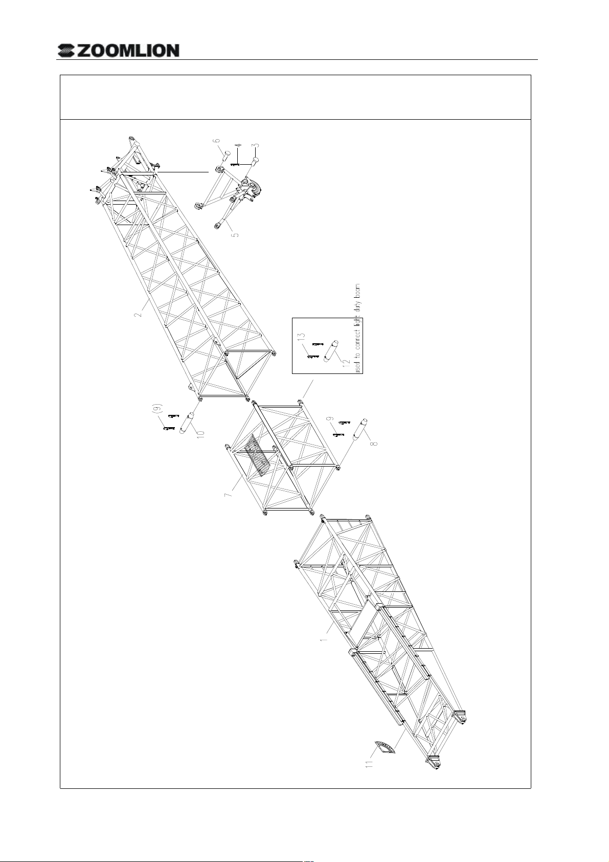
POS. ITEM DESCRIPTION & SPECIFICATION QTY.
1 00663400120200000 Main boom pivot section 1
2 00663400120400000 Main boom head assy. 1
3 00663300100001151 Pin spindle 2
4 00663300100001140 Retaining spring 4
5 00663400100800001 Tip boom assy. 1
6 00663300200001030 Pin spindle 2
7 00663400101000000 3 main boom intermediate section 1
8 00663400101200000 6m main boom intermediate section 1
9 00663400101400000 9m main boom intermediate section 6
10 00663400101600001 4m reducing section 1
11 00663300100001082 Pin spindle 34
12 00663300100001230 Retaining pin 72
13 00663300100001132 Pin spindle 2
14 00663300102200000 Angle indicator 1
15 00663400100001040 Pin spindle 4
16 00663604100001050 Retaining pin 8
17 00663400112400001 Main boom pivot section attachments assembly 1
17 00663400102400001 Main boom pivot section attachments assembly 1
18 00663400102600000 main boom head attachments assembly 1
19 00663400101800000
20 00663400102000000
21 00663400102200000
22 00663400102800000 4m reducing section attachments assembly 1
3m main boom intermediate section attachments
assembly
6m main boom intermediate section attachments
assembly
9m main boom intermediate section attachments
assembly
1
1
6
Note: Pos. 17 to 23 are not shown in the drawing.
Page 20

CRAWLERCRANE
MAINBOOMHEADASSY. D00663400120400000Y
Page 21

010040-1 BOOM SYSTEM
MAIN BOOM HEAD ASSY.
D00663400120400000Y
POS. ITEM DESCRIPTION & SPECIFICATION QTY.
1 00663400120410000 Main boom head 1
2 00663300101601390 Brass bush 2
3 1040100061 Screw M10*20-22H GB73-1985 2
4 00663400100401381 Spacing sleeve 1
5 00663400100401391 Spacing sleeve 1
6 00663400100401470 Deflection pulley spindle 1
7 00663400100401401 Spacing sleeve 1
8 00663400100401411 Pipe 1
9 1040500047 Cotter pin 5*70 GB/T91-2000 4
10 00663300100001010 Spacing sleeve 1
11 00663300111601100 Retaining plate 2
12 1040000090 Bolt M10*30-8.8 GB/T5783-2000 4
13 1040300067 Washer 10 GB/T93-1987 4
14 00663400100401421 Pipe 1
15 00663400100401431 Shaft 1
16 6340000055 Retaining plate 130 4
17 1040000082 Bolt M16*40-8.8 GB/T5783-2000 8
18 1040300065 Washer 16 GB/T93-1987 8
19 00663400100401510 Spacing sleeve 9
20 00663400100450000 Pulley 10
21 00663400100460000 Left connecting plate assy. 1
22 00663400100470001 Connecting plate 2
23 00663400100480000 Right connecting plate assy. 1
24 00663400100401520 Spacing sleeve 2
25 00663400100401500 Spacing sleeve 2
26 00663400100401490 Pin spindle 4
27 1140300189 Retainer ring 65 GB/T894.1-1986 4
28 00663300111601010 Pin spindle 4
29 00663302100200002 Pulley assy. 3
30 00663200102410000 Mounting bracket
31 1040500126 Cotter pin 5*26 GB/T91-2000
32 204110014 Lithium base grease ZL-2
33 00663200102401010 Pad
34 00663400100410000 Mounting bracket
35 006340000032 Retaining spring (D16,18,20)
36 1040000304 Bolt M4*40-8.8 GB/T5783-2000
**
1
1
1
2
1
1
2
Page 22

010040-1 BOOM SYSTEM
MAIN BOOM HEAD ASSY.
D00663400120400000Y
POS. ITEM DESCRIPTION & SPECIFICATION QTY.
37 1040200100 Nut M4-8 GB/T6170-2000
38 1040300044 Washer 4 GB/T93-1987
39 1040500186 Cotter pin 10*90 GB/T91-2000
40 00663606600401050 Rod
41 1040500353 Retaining spring (D30,32,35)
2
2
4
1
1
**
Page 23

2-6
Page 24
MAIN BOOM HEAD ATTACHMENTS ASSEMBLY
D00663300102600001Y
2-7
Page 25

MAIN BOOM HEAD ATTACHMENTS ASSEMBLY
D00663300102600001Y
POS.
ITEM DESCRIPTION & SPECIFICATION QTY.
1 00663300102000000 Rope support 1
2 1991900004 Grating RD-QUY400-10 1
3 1991900007 Grating RD-QUY400-6 3
4 1991900001 Chuck plate RD-QUY400-16 24
5 00663600102401050 Plate 14
6 1040100166 Screw M10*50-8.8 GB/T70.1-2000 24
7 1040200113 Nut M10-8 GB/T6170-2000 24
8 1040300067 Washer 10 GB/T93-1987 24
9 1991900003 Connecting plate RD-QUY400-17 5
2-8
Page 26

MAIN BOOM PIVOT SECTION ATTACHMENTS ASSEMBLY
D00663400102400001Y
2-9
Page 27

MAIN BOOM PIVOT SECTION ATTACHMENTS ASSEMBLY
D00663400102400001Y
POS.
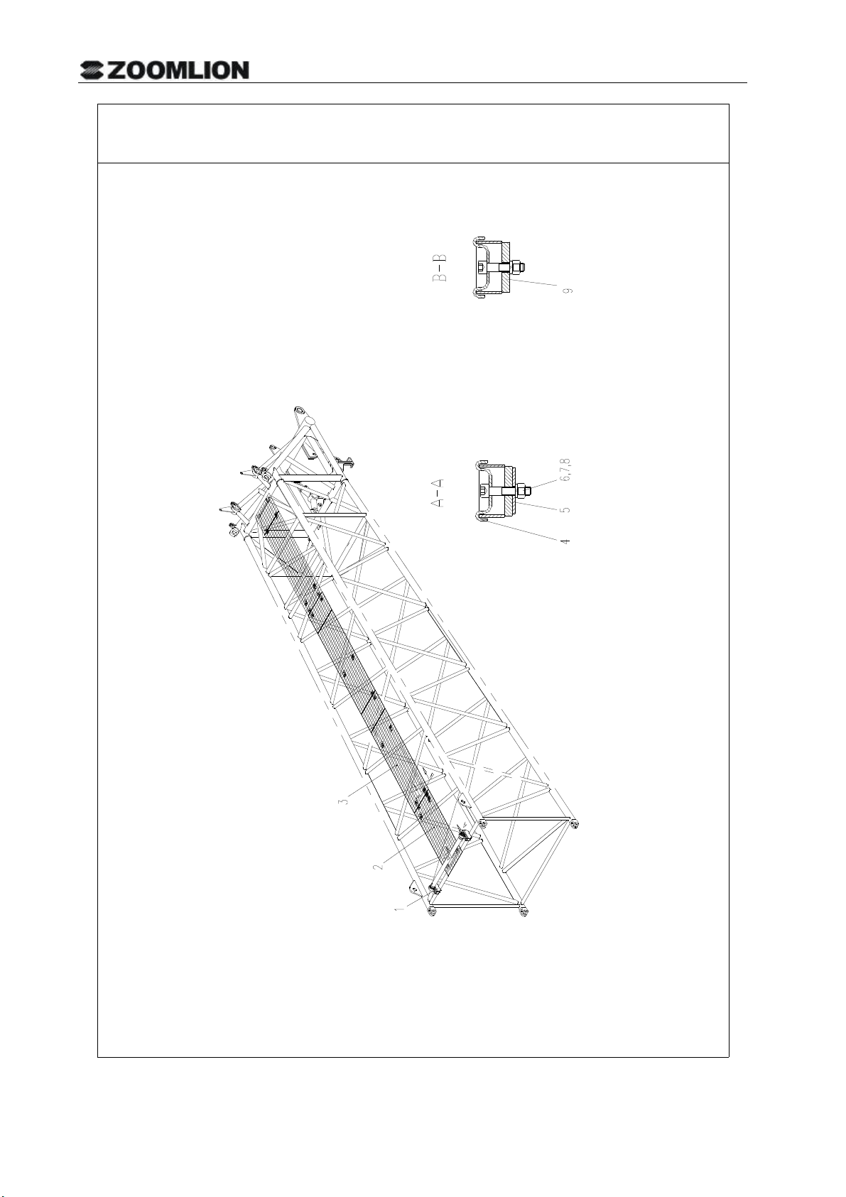
ITEM DESCRIPTION & SPECIFICATION QTY.
1 1991900006 Grating RD-QUY400-7 1
2 1991900008 Grating RD-QUY400-23 1
3 00663300102000000 Rope support 1
4 1991900010 Grating RD-QUY600-1 1
5 1991900009 Grating 400*480 RD-QUY600-14 2
6 1991900007 Grating RD-QUY400-6 1
7 1991900001 Chuck plate RD-QUY400-16 32
8 00663600102401050 Plate 24
9 1040100166 Screw M10*50-8.8 GB/T70.1-2000 32
10 1040200113 Nut M10-8 GB/T6170-2000 32
11 1040300067 Washer 10 GB/T93-1987 32
12 1991900003 Connecting plate RD-QUY400-17 4
2-10
Page 28
MAIN BOOM PIVOT SECTION ATTACHMENTS ASSEMBLY
D00663400112400001Y
2-11
Page 29

MAIN BOOM PIVOT SECTION ATTACHMENTS ASSEMBLY
D00663400112400001Y
POS.
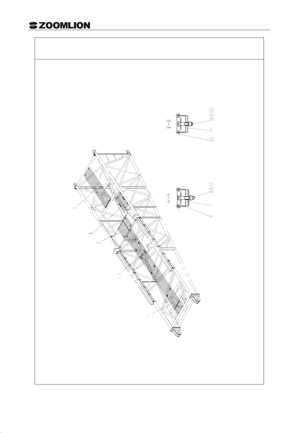
ITEM DESCRIPTION & SPECIFICATION QTY.
1 1991900006 Grating RD-QUY400-7 1
2 1991900008 Grating RD-QUY400-23 1
3 1991900010 Grating RD-QUY600-1 1
4 1991900009 Grating 400*480 RD-QUY600-14 2
5 1991900007 Grating RD-QUY400-6 1
6 1991900001 Chuck plate RD-QUY400-16 32
7 00663600102401050 Plate 24
8 1040100166 Screw M10*50-8.8 GB/T70.1-2000 32
9 1040200113 Nut M10-8 GB/T6170-2000 32
10 1040300067 Washer 10 GB/T93-1987 32
11 1991900003 Connecting plate RD-QUY400-17 4
2-12
Page 30
ROPE SUPPORT
D00663300102000000Y
2-13
Page 31

ROPE SUPPORT
D00663300102000000Y
POS.
ITEM DESCRIPTION & SPECIFICATION QTY.
1 1040000169 Bolt M12*45-8.8 GB/T5783-2000 4
2 1040300041 Washer 12-200HV GB/T97.1-2002 4
3 1040300054 Washer 12 GB/T93-1987 4
4 1040200096 Nut M12-8 GB/T6170-2000 4
5 00663300102010000 Rope support 1
6 1050200136 Bearing 290507 GB3882-1987 2
2-14
Page 32

ANGLE INDICATOR
D00663300102200000Y
2-15
Page 33

ANGLE INDICATOR
D00663300102200000Y
POS.
10
11
12
13
14
ITEM DESCRIPTION & SPECIFICATION QTY.
1
00663300102210000
2
00663300102220000
3
1040000267
4
1040300063
5
1040300066
6
00663300102201020
7
00663300102201030
8
1040300062
9
1040200111
1040100001
1040300045
1040300044
1040200100
00663300102201010
Base plate
Pointer
Bolt M8*20-8.8 GB/T5783-2000
Washer 8 GB/T93-1987
Washer 8-200HV GB/T97.1-2002
Washer
Fixing bolt
Washer 6 GB/T93-1987
Nut M6-8 GB/T6170-2000
Screw M8*20-4.8 GB/T818-2000
Washer 4-200HV GB/T97.1-2002
Washer 4 GB/T93-1987
Nut M4-8 GB/T6170-2000
Angle indicator
1
1
2
2
1
1
1
1
1
4
8
4
4
1
2-16
Page 34

TIP BOOM ASSY.
D00663400100800001Y
2-17
Page 35

TIP BOOM ASSY.
D00663400100800001Y
POS.
ITEM DESCRIPTION & SPECIFICATION QTY.
1 00663400100810001 Connecting support 1
2 00663400100820001 Connecting support 1
3 00663400100801010 Rope guard tube 1
4 1040500040 Cotter pin 6.3*50 GB/T91-2000 2
5 00663302100200002 Pulley assy. 1
6 00663300100001010 Spacing sleeve 2
7 6340000056 Retaining plate 120 2
8 1040000140 Bolt M16*45-10.9 GB/T5783-2000 4
9 1040300065 Washer 16 GB/T93-1987 4
10 6340000003 Retaining plate 50 2
11 1040000167 Bolt M10*55-8.8 GB/T5783-2000 4
12 1040300067 Washer 10 GB/T93-1987 4
13 00663400100801020 Shaft 1
14 00663400100801030 Shaft 1
15 204110014 Lithium base grease ZL-2 1
16 00663400100410000 Mounting bracket 1
17 00663200102401010 Pad 2
18 6340000032 Retaining spring (D16,18,20) 1
19 1040000304 Bolt M4*40-8.8 GB/T5783-2000 2
20 1040200100 Nut M4-8 GB/T6170-2000 2
21 1040300044 Washer 4 GB/T93-1987 2
2-18
Page 36

3M MAIN BOOM INTERMEDIATE SECTION ATTACHMENTSASSEMBLY
D00663300102800001Y
2-19
Page 37

3M MAIN BOOM INTERMEDIATE SECTION ATTACHMENTS ASSEMBLY
D00663300102800001Y
POS.
ITEM DESCRIPTION & SPECIFICATION QTY.
1 00663300102000000 Rope support 1
2 1991900008 Grating RD-QUY400-23 2
3 1991900001 Chuck plate RD-QUY400-16 12
4 00663600102401050 Plate 8
5 1040100166 Screw M10*50-8.8 GB/T70.1-2000 12
6 1040200113 Nut M10-8 GB/T6170-2000 12
7 1040300067 Washer 10 GB/T93-1987 12
8 1991900003 Connecting plate RD-QUY400-17 2
2-20
Page 38

6M MAIN BOOM INTERMEDIATE SECTION ATTACHMENTS ASSEMBLY
D00663300103000001Y
2-21
Page 39

6M MAIN BOOM INTERMEDIATE SECTION ATTACHMENTS ASSEMBLY
D00663300103000001Y
POS.
ITEM DESCRIPTION & SPECIFICATION QTY.
1 00663300102000000 Rope support 1
2 1991900005 Grating 2
3 1991900004 Grating 1
4 1991900001 Chuck plate 20
5 00663600102401050 Plate 12
6 1040100166 Screw M10*50-8.8 GB/T70.1-2000 20
7 1040200113 Nut M10-8 GB/T6170-2000 20
8 1040300067 Washer 10 GB/T93-1987 20
9 1991900003 Connecting plate RD-QUY400-17 4
2-22
Page 40

9M MAIN BOOM INTERMEDIATE SECTION ATTACHMENTS ASSEMBLY
D00663300103200001Y
2-23
Page 41

9M MAIN BOOM INTERMEDIATE SECTION ATTACHMENTS ASSEMBLY
D00663300103200001Y
POS.
ITEM DESCRIPTION & SPECIFICATION QTY.
1 00663300102000000 Rope support 2
2 1991900006 Grating RD-QUY400-7 2
3 1991900004 Grating RD-QUY400-10 24
4 1991900001 Chuck plate RD-QUY400-16 24
5 00663600102401050 Plate 2
6 1040100166 Screw M10*50-8.8 GB/T70.1-2000 24
7 1040200113 Nut M10-8 GB/T6170-2000 24
8 1040300067 Washer 10 GB/T93-1987 5
9 1991900003 Connecting plate RD-QUY400-17 14
2-24
Page 42

LUFFING JIB DERRICKING WINCH
D00663402000400002Y
2-25
Page 43

LUFFING JIB DERRICKING WINCH
D00663402000400002Y
POS.
ITEM DESCRIPTION & SPECIFICATION QTY.
1 1030200175 Winch reducer + motor 1
2 00663402000410002 Support 1
3 1040000141 Bolt M24*80-8.8 GB/T5782-2000 4
4 1040300049 Washer 24 GB/T93-1987 12
5 1040000198 Bolt M16*50-8.8 GB/T5783-2000 4
6 1040300065 Washer 16 GB/T93-1987 12
7 00663003100401010 Pin spindle 20
8 1040500047 Cotter pin 5*70 GB/T91-2000 20
9 204110014 Lithium base grease 1
10 204050019 Industrial closed gear oil 1
11 202230016 Loctite glue 262 1
13 1020400095 Lowering limiter 1
14 00663408200001040 Luffing rope Φ28-left-hand ordinary lay -1960 1
Note: Pos. 9 to 14 are not shown in the drawing.
2-26
Page 44

MAIN LOAD HOOK
D00663404100000001Y
2-27
Page 45

MAIN LOAD HOOK
D00663404100000001Y
POS.
ITEM DESCRIPTION & SPECIFICATION QTY.
1 00663304100001010 Main load hook 1
2 00663204100001150 Torsional spring 2
3 00663204100001140 Pin spindle 2
4 00663204100001130 Retaining plate 2
5 1040500040 Cotter pin 6.3*50 GB/T91-2000 2
6 1040000016 Bolt M16*35-8.8 GB/T5783-2000 4
7 6340000058 Shaft end stop shim 2
8 00663304100001020 Cross beam 1
9 6340000057 Two-hole retainer ring 170 2
10 1059900000 Bearing 9039438E GB5859-1986 1
11 00663304100001030 Hook nut 1
12 00663404100200001 Right side plate assy. 2
13 00663404100001011 Rod 2
14 6340000029 Retaining spring (D30,32,35) 4
15 00663804200430000 Pulley assy. 10
16 00663404100001021 Pulley spindle 1
17 1040100125 Screw M12*30-8.8 GB/T70.1-2000 8
18 1040300054 Washer 12 GB/T93-1987 10
19 00663604200201050 Shaft end cover 2
20 00663404100001031 Spacing sleeve 6
21 00663404100001040 Rope guard tube 2
22 00663604100230000 Safety pin 4
23 00663404100800000 Counterweight II 2
24 1040000077 Bolt M8*40-8.8 GB/T5783-2000 8
25 1040200183 Nut M8-10 GB/T6170-2000 12
26 1040300063 Washer 8 GB/T93-1987 12
27 00663404100001050 Connecting plate 4
28 00663304100001080 Locking plate 1
29 1040000108 Bolt M12*30-8.8 GB/T5783-2000 2
30 00663404100001070 Connecting beam 1
31 00663404100001080 Pin spindle 2
32 00663604200230000 Safety pin 2
33 1040100100 Screw M20 GB825-1988 2
34 204110014 Lithium base grease ZL-2 1
2-28
Page 46

LOAD HOOK (160/100T)
D00663404200200002Y
2-29
Page 47

LOAD HOOK (160/100T)
D00663404200200002Y
POS.
ITEM DESCRIPTION & SPECIFICATION QTY.
1 00663204100001120 Straight shank twin hook 1
2 00663204100001130 Retaining plate 2
3 00663204100001140 Pin spindle 2
4 00663204100001150 Torsional spring 2
5 1040500040 Cotter pin 6.3*50 GB/T91-2000 2
6 00663404200201050 Cross beam 1
7 6340000058 Shaft end stop shim 2
8 1040000016 Bolt M16*35-8.8 GB/T5783-2000 4
9 6340000057 Two-hole retainer ring 170 2
10 1050200137 Bearing 9039434E GB5859-1986 1
11 00663204100001100 Hook nut 1
12 00663404200210001 Right side plate assy. 2
13 00663404200201011 Rope guard tube 2
14 6340000029 Retaining spring (D30,32,35) 4
15 00663404200201021 Pulley spindle 1
16 1040100125 Screw M12*30-8.8 GB/T70.1-2000 8
17 1040300054 Washer 12 GB/T93-1987 12
18 00663604200201050 Shaft end cover 2
19 00663604200221050 Retainer ring 9
20 00663804200430000 Pulley assy. 6
21 00663604100230000 Safety pin 4
22 00663404200201041 Rod 2
23 1040000077 Bolt M8*40-8.8 GB/T5783-2000 8
24 1040200183 Nut M8-10 GB/T6170-2000 8
25 1040300063 Washer 8 GB/T93-1987 8
26 00663404100001060 Connecting plate 4
27 00663404200230002 Counterweight assy. 2
28 00663204100001160 Locking plate 1
29 1040000108 Bolt M12*30-8.8 GB/T5783-2000 2
30 1040100100 Screw M20 GB825-1988 2
31 204110014 Lithium base grease ZL-2 1
32 1080000001 Oil cup M10*1 GB1152-1979 1
Note: Pos. 31 and 32 are not shown in the drawing.
2-30
Page 48

LOAD HOOK (50T)
D00663404200400002Y
2-31
Page 49

LOAD HOOK (50T)
D00663404200400002Y
POS.
ITEM DESCRIPTION & SPECIFICATION QTY.
1 00663404200401010 Hook 1
2 00663014100001070 Retaining plate 1
3 00663014100001080 Torsional spring 1
4 1040500166 Pin spindle B12*95 GB/T882-1986 1
5 1040500075 Cotter pin 4*20 GB/T91-2000 1
6 6340000005 Two-hole retainer ring 120 2
7 6340000050 Shaft end stop shim 2
8 1040000114 Bolt M10*25-8.8 GB/T5783-2000 4
9 00663304200401011 Cross beam 1
10 1050200075 Rolling bearing 8324 GB301-1984 1
11 00663204200401050 Hook nut 1
12 1040000279 Bolt M10*180-8.8 GB/T5782-2000 1
13 1040200113 Nut M10-8 GB/T6170-2000 1
14 1040300067 Washer 10 GB/T93-1987 1
15 00663404200401020 Rod 2
16 6340000029 Retaining spring (D30,32,35) 4
17 00663404200230002 Counterweight assy. 2
18 00663404200401030 Pulley spindle 1
19 1040100125 Screw M12*30-8.8 GB/T70.1-2000 8
20 1040300054 Washer 12 GB/T93-1987 8
21 00663604200201050 Shaft end cover 2
22 00663404200401040 Retainer ring 3
23 00663804200430000 Pulley assy. 2
24 00663404200410000 Side cover assy. 2
25 1040100100 Screw M20 GB825-1988 4
26 00663404200430000 Counterweight 2
27 00663604100230000 Safety pin 4
28 00663404200401050 Rope guard tube 2
29 1040000077 Bolt M8*40-8.8 GB/T5783-2000 12
30 1040200183 Nut M8-10 GB/T6170-2000 12
31 1040300063 Washer 8 GB/T93-1987 12
32 00663404100001060 Connecting plate 8
33 00663404200401060 Rod 2
34 1040200197 Nut M30-8 GB/T6170-2000 4
35 1040300010 Washer 30 GB/T93-1987 4
2-32
Page 50

LOAD HOOK (50T)
D00663404200400002Y
POS.
ITEM DESCRIPTION & SPECIFICATION QTY.
36 204110014 Lithium base grease ZL-2 1
37 1080000001 Oil cup M10*1 GB1152-1979 1
Note: Pos. 36 and 37 are not shown in the drawing.
2-33
Page 51

2-34
Page 52

30T LOAD HOOK
D00663304200600002Y
2-35
Page 53

30T LOAD HOOK
D00663304200600002Y
POS.
ITEM DESCRIPTION & SPECIFICATION QTY.
1 00663004200001070 Hook 1
2 00663004200001080 Safety catch 1
3 1040300041 Washer 12-200HV GB/T97.1-2002 1
4 00663004200001091 Pin 1
5 1040500068 Cotter pin 4×26 GB/T91-2000 1
6 00663004200001100 Torsional spring 1
7 00663004200001110 Sleeve ring 2
8 00663004200001120 Stop shim 2
9 1040000134 Bolt M16×25-8.8 GB/T5783-2000 4
10 00663004200001131 Retaining plate 2
11 00663004200001140 Cross beam 1
12 1050200043 Rolling bearing 8320 GB301-1984 1
13 00663104200201020 Hook nut 1
14 1040100139 Screw M12×45-33H GB72-1988 1
15 00663304200601011 Retaining rod 4
16 6340000029 Retaining spring (D30,32,35) 8
17 00663304200620000 Counterweight assy. 2
18 00663604200201050 Shaft end cover 2
19 1040300054 Washer 12 GB/T93-1987 10
20 1040100125 Screw M12×30-8.8 GB/T70.1-2000 8
21 00663304200601031 Pulley shaft 1
22 00663304200610001 Side plate assy. 2
23 00663304200601050 Rod 2
24 1040200197 Nut M30-8 GB/T6170-2000 4
25 1040300010 Washer 30 GB/T93-1987 4
26 1040300065 Washer 16 GB/T93-1987 8
27 1040200110 Nut M16-8 GB/T6170-2000 8
28 1040000297 Bolt M16×100-8.8 GB/T5782-2000 8
29 00663804200430000 Pulley assy. 1
30 00663304200601040 Spacing sleeve 2
31 204110014 Lithium base grease ZL-2 1
32 1080000001 Oil cup M10×1 GB1152-1979 1
Note: Pos. 31 and 32 are not shown in the drawing.
2-36
Page 54

LOAD HOOK (16t)
D00663804200800000Y
2-37
Page 55

LOAD HOOK (16t)
D00663804200800000Y
POS.
ITEM DESCRIPTION & SPECIFICATION QTY.
1 00663804200801010 Lifting ring bolt 1
2 1050200041 Rolling bearing 2
3 00663804200801020 Counterweight 1
4 00663804200810000 Hook 1
5 1040200197 Nut M30-8 GB/T6170-2000 2
6 1040300010 Washer 30 GB/T93-1987 2
7 00663804200801030 Threaded rod 1
8 1040300067 Washer 10 GB/T93-1987 2
9 1040000189 Bolt M10*120-8.8 GB/T5782-2000 2
10 1040200113 Nut M10-8 GB/T6170-2000 2
11 00663804200801040 Hook nut 2
12 1040500068 Cotter pin 4*26 GB/T91-2000 1
13 1040300041 Washer 12-200HV GB/T97.1-2002 1
14 1040500100 Pin spindle B12*90 GB/T882-1986 1
15 00663014200201070 Torsional spring 1
16 00663014200201060 Retaining plate 1
17 00663014200201050 Hook 1
18 204110014 Lithium base grease 1
2-38
Page 56

MAIN BOOM TILTING-BACK SUPPORT
D00663303100200000Y
2-39
Page 57

MAIN BOOM TILTING-BACK SUPPORT
D00663303100200000Y
POS.
ITEM DESCRIPTION & SPECIFICATION QTY.
1 00663303100210000 Inner pipe 1
2 00663303100201010 Spring 1
3 00663303100220000 Outer pipe 1
4 00663303100201020 Pipe spindle 1
5 00663303100201030 Retaining plate 2
6 1040000269 Bolt M16*30-8.8 GB/T5783-2000 4
7 1040300065 Washer 16 GB/T93-1987 4
8 1040500184 Pipe spindle B20*160 GB/T882-1986 1
9 1040500077 Cotter pin 5*30 GB/T91-2000 1
2-40
Page 58

MAIN BOOM ANCHORING RODS
D00663405400200001Y
2-41
Page 59

MAIN BOOM ANCHORING RODS
D00663405400200001Y
POS.
ITEM DESCRIPTION & SPECIFICATION QTY.
1 00663405400201020 Shaft 2
2 1040500187 Cotter pin 10×95 GB/T91-2000 10
3 00663405400220001 Anchoring rod connected to main boom 2
4 00663305400201020 Pin spindle 2
5 00663300100001230 Retaining pin 70
6 00663305400201031 Single-anchoring rod 16
7 00663305400201040 Pin spindle 68
8 00663305400220002 Double-anchoring rod 32
9 00663305400201051 Single-anchoring rod 18
10 00663405400260001 Double-anchoring rod 2
11 00663405400210001 Coupling link 1
12 00663405400201030 Shaft 8
13 00663405400230001 Double-anchoring rod 2
14 00663405400201040 Plate 1
15 1040500188 Cotter pin 12×120 GB/T91-2000 2
16 00663405400201050 Shaft 1
17 00663405400240000 Double-anchoring rod 1
18 00663405400201060 Plate 2
19 00663405400250000 Coupling link 1
20 1040500179 Cotter pin 10×120 GB/T91-2000 4
21 00663305400201090 Pin spindle 4
22 00663305400270000 Connecting plate 4
23 1040500076 Cotter pin 8×60 GB/T91-2000 2
24 00663305400201080 Pin spindle 2
2-42
Page 60

LIGHT ANCHORING RODS
D00663405401000001Y
2-43
Page 61

LIGHT ANCHORING RODS
D00663405401000001Y
POS.
ITEM DESCRIPTION & SPECIFICATION QTY.
1 00663305400201040 Pin spindle 8
2 00663300100001230 Retaining pin 8
3 00663305400220002 Double-anchoring rod 2
4 00663405401020000 Coupling link 1
5 00663405401001010 Anchoring rod 2
6 1040500187 Cotter pin 10×95 GB/T91-2000 4
7 00663405400860000 Coupling link 1
8 00663405400610001 Double-anchoring rod 2
9 00663405400601010 Pin spindle 4
10 00663405401001020 Anchoring rod 2
2-44
Page 62

INTERMEDIATE TENSIONERS ON LIGHT DUTY BOOM
D00663405401200001Y
2-45
Page 63

INTERMEDIATE TENSIONERS ON LIGHT DUTY BOOM
D00663405401200001Y
POS.
ITEM DESCRIPTION & SPECIFICATION QTY.
1 00663405401210001 Double-anchoring rod 2
2 00663405400601030 Pin spindle 4
3 00663405401201010 Plate 2
4 00663405401201020 Plate 2
5 00663405401220001 Double-anchoring rod 2
6 00663405400601010 Pin spindle 4
7 00663300100001230 Retaining pin 8
2-46
Page 64

FIXED JIB
D00663300200000001Y
2-47
Page 65

Note: Pos. 15 and 16 are not shown in the drawing and the Pos. 15 is used to secure the anchoring
FIXED JIB
D00663300200000001Y
POS.
ITEM DESCRIPTION & SPECIFICATION QTY.
1 00663300200200000 Fixed jib pivot section 1
2 00663300200400001 6m fixed jib intermediate section 3
3 00663300200600002 Fixed jib head assy. 1
4 1040000177 Bolt M16*55-8.8 GB/T5783-2000 8
5 1040300065 Washer 16 GB/T93-1987 8
6 00663300200001070 Retaining plate 4
7 00663300200001020 Retaining spring 2
8 00663300200001010 Pin spindle 2
9 00663300200001040 Retaining spring 2
10 00663300200001080 Nylon plate 11
11 1040300094 Washer 8-140HV GB/T96.1-2002 22
12 1040000267 Bolt M8*20-8.8 GB/T5783-2000 22
13 00663300200001050 Pin spindle 16
14 00663300200001060 Retaining spring 32
15 00663300100001230 Retaining pin 16
16 1080000002 Oil cup M10*1 GB1152-1989 2
rods placed on fixed jib.
2-48
Page 66

FIXED JIB HEAD
D00663300200600002Y
2-49
Page 67

FIXED JIB HEAD
D00663300200600002Y
POS.
ITEM DESCRIPTION & SPECIFICATION QTY.
1 00663300200610002 Fixed jib head 1
2 00663300200601031 Anchoring rod 2
3 00663300200601090 Rope guard tube 3
5 1040500040 Cotter pin 6.3*50 GB/T91-2000 6
6 00663300100001010 Spacing sleeve 2
7 1040200102 Nut M24-8 GB/T6170-2000 2
8 1040300049 Washer 24 GB/T93-1987 2
9 00663300200601070 Shaft 1
10 00663300200620001 Running wheel assembly 2
11 1040200185 Nut M60*2 GB/T812-1988 2
12 1040300087 Washer 60 GB/T858-1988 2
13 1080000002 Oil cup M10*1 GB1152-1989 2
14 00663306601001021 Shaft 1
15 00663306601001060 Spacing sleeve 3
16 00663302100200002 Pulley assy. 3
17 00663306601001070 Spacing sleeve 1
18 6340000056 Retaining plate 120 4
19 1040000065 Bolt M16*45-8.8 GB/T5783-2000 8
20 1040300065 Washer 16 GB/T93-1987 8
21 00663300200601020 Washer 2
22 00663306601001080 Spacing sleeve 1
23 00663600200601080 Spacing sleeve 2
24 00663306601001100 Top cap 2
25 00663300200601080 Threaded rod 1
26 1040500057 Cotter pin 5*50 GB/T91-2000 2
27 204110014 Lithium base grease ZL-2 1
28 00663400100410000 Mounting bracket 1
29 00663200102401010 Pad 2
30 6340000032 Retaining spring (D16,18,20) 1
31 1040000304 Bolt M4*40-8.8 GB/T5783-2000 2
32 1040200100 Nut M4-8 GB/T6170-2000 2
33 1040300044 Washer 4 GB/T93-1987 2
2-50
Page 68

FIXED JIB FRONT ANCHORING RODS
D00663305400600000Y
2-51
Page 69

FIXED JIB FRONT ANCHORING RODS
D00663305400600000Y
POS.
ITEM DESCRIPTION & SPECIFICATION QTY.
1 00663305400410003 Double-anchoring rod 12
2 00663305400401010 Pin spindle 28
3 00663300100001230 Retaining pin 28
4 00663305400420000 Reducing double-anchoring rod 1
5 00663305401010001 Reducing single-anchoring rod 1
6 00663305400401031 Single-anchoring rod 10
7 00663305400620001 Double-anchoring rod 2
8 1040500186 Cotter pin 10×90 GB/T91-2000 1
9 00663305400401060 Pin spindle 1
2-52
Page 70

LUFFING JIB REAR ANCHORING RODS
D00663405400600001Y
2-53
Page 71

FIXED JIB REAR ANCHORING RODS
D00663405400400001Y
POS.
ITEM DESCRIPTION & SPECIFICATION QTY.
1 00663405400401010 Sleeve 2
2 1040500097 Cotter pin 4×30 GB/T91-2000 2
3 1040200097 Nut M20-8 GB/T6170-2000 2
4 1040000323 Bolt M20×200-8.8 GB/T31.1-1988 2
5 00663405400410000 Anchoring rod 4
6 00663405400401020 Single-anchoring rod 2
7 00663305400410003 Double-anchoring rod 8
8 00663305400401010 Pin spindle 22
9 00663300100001230 Retaining pin 22
10 00663305400801021 Single-anchoring rod 4
11 00663305400440000 Coupling link 1
12 00663305400430001 Double-anchoring rod 2
13 00663305400401020 Connecting plate 1
14 00663305400401060 Pin spindle 1
15 1040500186 Cotter pin 10×90 GB/T91-2000 1
16 00663305400420000 Double reducing piece 1
17 00663305400401041 Single-anchoring rod 2
18 00663405400401030 Single-anchoring rod 2
2-54
Page 72

FA-FRAME
D00663307800000002Y
2-55
Page 73

FA-FRAME
D00663307800000002Y
POS.
ITEM DESCRIPTION & SPECIFICATION QTY.
1 00663307800200002 FA-frame 1
2 00663308000001030 Pipe 1
3 00663606600001140 Guide roller 1
4 1040500057 Cotter pin 5*50 GB/T91-2000 1
5 00663302100200002 Pulley assy. 1
6 1040300107 Retainer ring 120 GB/T894.1-1986 1
7 00663306601001070 Spacing sleeve 2
8 00663308000001040 Shaft 1
9 1040500076 Cotter pin 8*60 GB/T91-2000 2
10 1040000069 Bolt M12*25-8.8 GB/T5783-2000 4
11 1040300054 Washer 12 GB/T93-1987 4
12 00663307800001040 Retaining plate 2
13 00663307800001020 Spacing sleeve 1
14 00663307800001030 Anchoring rod 4
15 00663307800001010 Shaft 1
2-56
Page 74

FRONT TILTING-BACK SUPPORT OF FIXED JIB
D00663303100600000Y
2-57
Page 75

FRONT TILTING-BACK SUPPORT OF FIXED JIB
D00663303100600000Y
POS. ITEM DESCRIPTION & SPECIFICATION QTY.
1 00663303100610000 Outer pipe 1
2 00663303100601010 Spring 1
3 00663303100620000 Inner pipe 1
4 00663308000001020 Pin spindle 1
5 1040500076 Cotter pin 8*60 GB/T91-2000 1
2-58
Page 76

REAR TILTING-BACK SUPPORT OF FIXED JIB
D00663303100400000Y
2-59
Page 77

REAR TILTING-BACK SUPPORT OF FIXED JIB
D00663303100400000Y
POS.
ITEM DESCRIPTION & SPECIFICATION QTY.
1 00663303100410000 Outer pipe 1
2 00663303100401010 Spring 1
3 00663303100420000 Inner pipe 1
4 1040500076 Cotter pin 8×60 GB/T91-2000 2
5 00663308000001020 Pin spindle 1
2-60
Page 78

FIXED JIB FRONT ANCHORING RODS ( CRANE USED TO LIFT TUNNEL
BORING MACHINE)
D00663405411000000Y
2-61
Page 79

FIXED JIB FRONT ANCHORING RODS ( CRANE USED TO LIFT TUNNEL BORING MACHINE)
D00663405411000000Y
POS.
ITEM DESCRIPTION & SPECIFICATION QTY.
1 00663405411000050 Front anchoring rods assembly 1
2 00000001040500076 Cotter pin 8×60 GB/T91-2000 8
3 00663405400801031 Shaft 4
4 00663405400801020 Pin spindle 4
5 00663405400601090 Anchoring rod 2
6 00663300100001230 Retaining pin 8
7 00663405400601010 Pin spindle 8
8 00000001040500186 Cotter pin 10×90 GB/T91-2000 4
9 00663305400201041 Pin spindle 4
10 00663405400610001 Double-anchoring rod 2
2-62
Page 80

HEAVY FIXED JIB ASSY.
D00663400300000000Y
2-63
Page 81

HEAVY FIXED JIB ASSY.
D00663400300000000Y
POS.
ITEM DESCRIPTION & SPECIFICATION QTY.
1 00663400300200000 Heavy fixed jib 1
2 00663306601001110 Pipe 3
3 1040500057 Cotter pin 5*50 GB/T91-2000 6
4 00663302100200002 Pulley assy. 5
5 00663306601001130 Plate 2
6 00663300100001010 Spacing sleeve 4
7 00663407900001110 Anchoring rod 2
8 00663406600401120 Spacing sleeve 1
9 00663406600430000 Ring 1
10 00663406600401110 Spacing sleeve 5
11 1040000090 Bolt M10*30-8.8 GB/T5783-2000 16
12 1040300067 Washer 10 GB/T93-1987 16
13 00663306601001070 Spacing sleeve 3
14 00663306601001120 Shaft 1
15 00663300200620001 Running wheel assembly 2
16 1040200185 Nut M60*2 GB/T812-1988 2
17 1040300087 Washer 60 GB/T858-1988 2
18 1080000002 Oil cup M10*1 GB1152-1989 2
19 00663406600401130 Shaft 1
20 1040000065 Bolt M16*45-8.8 GB/T5783-2000 8
21 6340000056 Retaining plate 120 4
22 1040300065 Washer 16 GB/T93-1987 16
23 1040300044 Washer 4 GB/T93-1987 2
24 1040200100 Nut M4-8 GB/T6170-2000 2
25 1040000304 Bolt M4*40-8.8 GB/T5783-2000 2
26 6340000032 Retaining spring (D16,18,20) 1
27 00663400100410000 Mounting bracket 1
28 00663200102401010 Pad 2
29 00663300200001070 Retaining plate 4
30 1040000177 Bolt M16*55-8.8 GB/T5783-2000 8
31 00663300200001010 Pin spindle 2
32 00663300200001020 Retaining spring 2
33 00663300200001040 Retaining spring 2
34 00663300200001030 Pin spindle 2
35 204110014 Lithium base grease ZL-2 1
2-64
Page 82

FRONT ANCHORING RODS OF HEAVY FIXED JIB
D00663405401400000Y
2-65
Page 83

FRONT ANCHORING RODS OF HEAVY FIXED JIB
D00663405401400000Y
POS.
ITEM DESCRIPTION & SPECIFICATION QTY.
1 00663405400601010 Pin spindle 2
2 00663300100001230 Retaining pin 12
3 00663405401410001 Double-anchoring rod 2
4 00663305400401031 Single-anchoring rod 2
5 00663305400410003 Double-anchoring rod 4
6 00663305401010001 Single-reducing piece 1
7 00663305400401060 Pin spindle 1
8 1040500186 Cotter pin 10×90 GB/T91-2000 1
9 00663305400420000 Double-reducing piece 1
10 00663305400401010 Pin spindle 10
2-66
Page 84

FIXED JIB REAR ANCHORING RODS ( CRANE USED TO LIFT TUNNEL
BORING MACHINE )
D00663405411200000Y
2-67
Page 85

FIXED JIB REAR ANCHORING RODS (CRANE USED TO LIFT TUNNEL BORING MACHINE)
D00663405411200000Y
POS. ITEM DESCRIPTION & SPECIFICATION QTY.
1 00663405411200030 Front anchoring rods assembly 1
2 00663300100001230 Retaining pin 28
3 00663405400601010 Pin spindle 28
4 00663405400610001 Double-anchoring rod 12
5 00663305400201041 Pin spindle 4
6 1040500186 Cotter pin 10×90 GB/T91-2000 4
7 00663405400601080 Anchoring rod 4
8 00663405400601090 Anchoring rod 6
9 00663405400640001 Double-anchoring rod 2
2-68
Page 86

CRAWLERCRANE
LUFFINGJIB D00663406620000000Y
Page 87

660-2 BOOM SYSTEM
LUFFING JIB
D00663406620000000Y
POS. ITEM DESCRIPTION & SPECIFICATION QTY.
1 00663406620200000 Luffing jib pivot section 1
2 00663406600400001 Luffing jib head assy. 1
3 00663406620400000 3m luffing jib intermediate section 1
4 00663406620600000 6m luffing jib intermediate section (7mm) 2
5 1040100109 Screw M10×25-4.8 GB/T819.1-2000 4
6 00663306600001050 Pad 2
7 00663406601000000 9m luffing jib intermediate section 2
8 00663406601200001 Tip boom assy. 1
9 00663306601800000 Pendulum 2
10 1040100182 Screw M12 GB825-1988 2
11 006340000029 Retaining spring (D30,32,35) 2
12 00663306600001060 Pin spindle 2
13 1040300094 Washer 8-140HV GB/T96.1-2002 28
14 1040000267 Bolt M8×20-8.8 GB/T5783-2000 28
15 00663300200001080 Nylon plate 14
16 00663300100001230 Retaining pin 44
17 00663306600001071 Retaining plate 2
18 1040000094 Bolt M12×35-8.8 GB/T5783-2000 16
19 1040300054 Washer 12 GB/T93-1987 16
20 00663406600001031 Shaft 2
21 1040000177 Bolt M16×55-8.8 GB/T5783-2000 4
22 1040300065 Washer 16 GB/T93-1987 4
23 00663300200001071 Retaining plate 2
24 00663406600001051 Shaft 2
25 00663300200001040 Retaining spring 2
26 1080000002 Oil cup M10×1 GB1152-1989 4
27 00663406600001011 Pin spindle 28
28 006340000001 Retaining spring (D40,45) 32
29 00663406601400000 3m luffing jib intermediate section attachments welded 1
30 00663406601600000 6m luffing jib intermediate section attachments welded 2
31 00663406601800000 9m luffing jib intermediate section attachments welded 3
32 00663106600001020 Retaining plate 2
33 00663406620800000 9m luffing jib intermediate section (7mm) 1
Note: Pos. 29 to 31 are not shown in the drawing.
Page 88

LUFFING JIB HEAD ASSY.
D00663406600400001Y
2-71
Page 89

LUFFING JIB HEAD ASSY.
D00663406600400001Y
POS.
ITEM DESCRIPTION & SPECIFICATION QTY.
1 00663406600420000 Luffing jib head 1
2 00663606601610000 Supporting seat 2
3 1040500173 Cotter pin 6.3×80 GB/T91-2000 2
4 00663100100420000 Supporting seat 1
5 1040500126 Cotter pin 5×26 GB/T91-2000 1
6 00663306601001110 Pipe 3
7 1040500057 Cotter pin 5×50 GB/T91-2000 6
8 00663302100200002 Pulley assy. 5
9 00663306601001130 Plate 2
10 00663300100001010 Spacing sleeve 4
11 00663407900001110 Anchoring rod 2
12 00663406600401110 Spacing sleeve 5
13 00663406600430000 Ring 1
14 00663406600401120 Spacing sleeve 1
15 1040000090 Bolt M10×30-8.8 GB/T5783-2000 16
16 Washer 10 GB/T93-1987 16
17 00663306601001120 Shaft 1
18 00663300200620001 Running wheel assembly 2
19 1040200185 Nut M60×2 GB/T812-1988 2
20 1040300087 Washer 60 GB/T858-1988 2
21 1080000002 Oil cup M10×1 GB1152-1989 2
22 00663406600401130 Shaft 1
23 1040000065 Bolt M16×45-8.8 GB/T5783-2000 8
24 6340000056 Retaining plate 120 4
25 1040300065 Washer 16 GB/T93-1987 8
26 00663306601001070 Spacing sleeve 3
27 6340000032 Retaining spring (D16,18,20) 1
28 00663400100410000 Mounting bracket 1
29 00663200102401010 Pad 2
30 1040200100 Nut M4-8 GB/T6170-2000 2
31 1040300044 Washer 4 GB/T93-1987 2
32 1040000304 Bolt M4×40-8.8 GB/T5783-2000 2
33 00663300200601020 Washer 2
2-72
Page 90

TIP BOOM ASSY.
D00663406601200001Y
2-73
Page 91

TIP BOOM ASSY.
D00663406601200001Y
POS. ITEM DESCRIPTION & SPECIFICATION QTY.
1 1040500184 Pin spindle B20×160 GB/T882-1986 2
2 6340000032 Retaining spring (D16,18,20) 4
3 1040300106 Washer 20-200HV GB/T97.1-2002 2
4 00663406601210001 Connecting support 1
5 00663406601201020 Pin spindle 1
6 6340000001 Retaining spring (D40,45) 3
7 00663406601230000 Double-anchoring rod 1
8 1040500201 Pin spindle B40×100 GB/T882-1986 1
9 00663406601240000 Single-anchoring rod 1
10 00663406601201030 Pin spindle 1
11 6340000056 Retaining plate 120 2
12 1040000065 Bolt M16×45-8.8 GB/T5783-2000 4
13 1040300065 Washer 16 GB/T93-1987 8
14 00663400100801010 Rope guard tube 1
15 1040300064 Washer 16-140HV GB/T96.1-2002 4
16 1040200110 Nut M16-8 GB/T6170-2000 4
17 00663200100801020 Spacing sleeve 2
18 00663400100801030 Shaft 1
19 00663302100200002 Pulley assy. 1
20 00663406601201040 Roller 4
21 00663406601201050 Pipe 4
2-74
Page 92

CRAWLERCRANE
LUFFINGJIBFRONTANCHORINGRODS D00663405401800000Y
Page 93

540080-2 BOOM SYSTEM
LUFFING JIB FRONT ANCHORING RODS
D00663405401800000Y
POS. ITEM DESCRIPTION & SPECIFICATION QTY.
1 1040500076
2 00663405401801040 Pin spindle 4
3 00663405400850000 Anchoring rod 8
4 00663405400801020 Pin spindle 4
5 00663405400830000 Coupling link 1
6 1040500186
7 00663305400201041 Pin spindle 8
8 00663405400650001 Anchoring rod 2
9 00663305400201061 Connecting plate 1
10 1040500179
11 00663305400201101 Pin spindle 1
12 00663305400250001 Connecting plate 1
13 00663405400801040 Anchoring rod 2
14 00663405400860000 Coupling link 1
15 00663405400601010 Pin spindle 52
16 00663300100001230 Retaining pin 56
17 00663405400610001 Double-anchoring rod 24
Cotter pin 8×60 GB/T91-2000
Cotter pin 10×90 GB/T91-2000
Cotter pin 10×120 GB/T91-2000
8
8
1
18 00663405400801050 Anchoring rod 2
19 00663405400601080 Anchoring rod 12
20 00663405400601090 Anchoring rod 10
21 00663405400870001 Double-anchoring rod 2
22 00663405401801010 Anchoring rod 2
23 00663405401810000 Double-anchoring rod 2
24 00663405401801020 Anchoring rod 2
25 00663405401820000 Double-anchoring rod 2
26 00663405401801030 Anchoring rod 2
Page 94

CRAWLERCRANE
WAFRAME1 D00663408020000000Y
Page 95

800-2 BOOM SYSTEM
WA-FRAME 1
D00663408020000000Y
POS. ITEM DESCRIPTION & SPECIFICATION QTY.
1
00663408020200000
2 00663407900001120 Pipe 1
3 00663606600001140 Guide roller 7
4 1040500057 Cotter pin 5×50 GB/T91-2000 4
5 00663302100200002 Pulley assy. 7
6 1040300107 Retainer ring 120 GB/T894.1-1986 1
7 00663306601001070 Spacing sleeve 4
8 00663407900001130 Shaft 1
9 00663308000001050 Plate 2
10 00663407900001110 Anchoring rod 2
11
00663407900001140 Spacing sleeve
12
00663308000001070 Partition plate
13
00663408000001120 Shaft
14
00663407900001150 Spacing sleeve
15
00663407900001160 Spacing sleeve
16
00663407900001100 Rod
17
1040000069
WA-frame 1 1
12
5
1
2
2
1
Bolt M12×25-8.8 GB/T5783-2000
6
18
1040300054 Washer 12 GB/T93-1987
6
Page 96

CRAWLERCRANE
WAFRAME2 D00663407920000000Y
Page 97

790-2 BOOM SYSTEM
WA-FRAME 2
DD00663407920000000Y
POS. ITEM DESCRIPTION & SPECIFICATION QTY.
1 00663407920200000 WA-frame 2 1
2 00663308000001030 Pipe 2
3 00663606600001140 Guide roller 9
4 1040500057 Cotter pin 5×50 GB/T91-2000 8
5 00663302100200002 Pulley assy. 9
6 1040300107 Retainer ring 120 GB/T894.1-1986 3
7 00663306601001070 Spacing sleeve 8
8 00663308000001040 Shaft 2
9 00663308000001050 Plate 2
10 00663407900001110 Anchoring rod 2
11 00663308000001070 Partition plate 5
12 00663408000001120 Shaft 1
13 00663407900001100 Rod 1
14 00663308000001020 Pin spindle 2
15 1040500076 Cotter pin 8×60 GB/T91-2000 2
16 1040000069 Bolt M12×25-8.8 GB/T5783-2000 6
17 1040300054 Washer 12 GB/T93-1987 6
18 00663407900001120 Pipe 1
19 00663407900001130 Shaft 1
20 00663307900001050 Shaft bush 2
21 00663407900001140 Spacing sleeve 12
22 00663407900001150 Spacing sleeve 2
23 00663407900001160 Spacing sleeve 2
24 1040000098 Bolt M8×16-8.8 GB/T5783-2000 8
25 1040300063 Washer 8 GB/T93-1987 8
26 00663407920001010 Nylon block 2
Page 98

LUFFING JIB REAR ANCHORING ROD
D00663405400600001Y
S
塔式副臂后拉板
2-81
Page 99

LUFFING JIB REAR ANCHORING RODS
D00663405400600001Y
POS.
ITEM DESCRIPTION & SPECIFICATION QTY.
1 00663300100001230 Retaining pin 60
2 00663405400610001 Double-anchoring rod 28
3 00663405400601010 Pin spindle 60
4 00663405400830000 Coupling link 1
5 1040500186 Cotter pin 10×90 GB/T91-2000 8
6 00663305400201040 Pin spindle 8
7 00663405400650001 Anchoring rod 2
8 00663305400201061 Connecting plate 1
9 00663305400201101 Pin spindle 1
10 1040500179 Cotter pin 10×120 GB/T91-2000 1
11 00663305400250001 Connecting plate 1
12 00663405400601060 Anchoring rod 2
13 00663405400620000 Coupling link 1
14 00663405400601070 Anchoring rod 2
15 00663405400601080 Anchoring rod 10
16 00663405400601090 Anchoring rod 14
17 00663405400640001 Double-anchoring rod 2
2-82
Page 100

REAR TILTING-BACK SUPPORT OF LUFFING JIB
D00663403100800002Y
2-83
 Loading...