

Page 1

HIRSCHMANN
Load Moment Indicator
for Crawler Crane
HC3901
Operator’s Manual
Hirschmann Electronics(Shanghai)Co.,Ltd
Suite 12A, Huamin Empire Plaza, No.726, West Yan An Road, Shanghai, P.R.China
Tel: 021-51082780
Fax: 021-52375899
Zipcode: 200050
Website: http://www.hirschmann.com
Page 2

Copyright
This document contains propriety information which is protected by copyright, and all rights are
reserved. No part of this manual may be photocopied, reproduced or translated to another language
without prior written approval of Hirschmann Electronics (Shanghai) Co., Ltd.
Declaration
All information in this document is subject to change without notice.
Hirschmann makes no warranty of any kind with regard to this material, including, but not limited to,
the implied warranties of merchantability and fitness for a particular purpose.
Hirschmann will not be liable for errors contained herein or for incidental or consequential damages
in connection with reference to, and performance or use of this manual.
Applied Scope
This manual is made for the following crane manufacturer
Zoomlion
This manual can be applied to the following types of crawler cranes manufactured by the partner:
ZCC1100H
Special Notice
Using components of LMI rather than from Hirschmann may cause problems of inaccuracy and
even malfunction of the LMI system. We recommend you use genuine Hirschmann components and
parts during repairing and service. Hirschmann is not liable of any responsibilities in case genuine parts
are not used.
Rev. Date Prepared Checked Modifications
01 2014-08-04 Guo Tao Zhou Fei First issue, English
HC3901for Zoomlion ZCC1100H
Page 3

Table of Contents
1. GENERAL INFORMATION .................................................................................................................... 1
2. IMPORTANT NOTES .............................................................................................................................. 2
3. SYSTEM DESCRIPTION ......................................................................................................................... 3
3.1 HC3901 Controller ............................................................................................................................. 4
3.2 WG Angle Sensor ............................................................................................................................... 5
3.3
Force Sensor........................................................................................................................................ 6
4. OPERATION AND DISPLAY INTERFACE .......................................................................................... 7
4.1 Data display(values are only for example) .................................................................................... 8
4.2 EN13000 ............................................................................................................................................. 8
4.3Weight status bar .................................................................................................................................. 9
4.4 Indicator light ...................................................................................................................................... 9
5. OPERATION METHOD and PROCESS (only for example) ................................................................ 10
5.1 Reeving Setting ................................................................................................................................. 11
5.2 Function Setting ................................................................................................................................ 12
5.3 Error Code Information .................................................................................................................... 15
5.4 Angle Limit Setting ........................................................................................................................... 16
6. SYSTEM FUNCTIONS .......................................................................................................................... 17
6.1 Warning ............................................................................................................................................. 17
6.2 Prohibition ........................................................................................................................................ 17
7 INSPECTION MAINTENANCE AND CONSIDERATIONS ............................................................... 18
7.1 Inspection before Operation ............................................................................................................. 18
7.2 Routine Maintenance ........................................................................................................................ 18
7.3 Routine Consideration ...................................................................................................................... 18
7.4 Buzzer Alarms .................................................................................................................................. 18
7.5 Angle Sensor Adjustment ................................................................................................................. 18
8. TROUBLESHOOTING .......................................................................................................................... 19
Page 4

1. GENERAL INFORMATION
The load moment indicator HC3901 (hereinafter referred to as LMI) is applicable to the telescopic
boom crane, lattice boom crane, all- terrain crane and other types of cranes.
The HC3901 LMI can provide the crane operator with essential information required to operate the
crane within its design parameters. Using different sensors, LMI can provide the crane operator with
information on real time basis regarding boom length, boom angle, working height, working radius, rated
load and actual weight being lifted by the crane
The system operates on the principle of reference/real comparison. The boom angle is measured by
angle sensor that is mounted on the boom. The crane load is measured by force transducers attached to the
boom pendants. The real value, resulting from all the sensors measurement is compared with the
reference data, stored in the controller. If non-permitted conditions are approached, the LMI will warn the
operator by audible alarm, warning light and at the same time, some dangerous movements such as lifting
and luffing down will be stopped with the help of the crane control system.
This manual only gives guide for the LMI operation. Please refer to the Crane Operator’s Manual
provided by the crane manufacturer for detailed operating procedures of the crane.
1
Page 5
Operator’s Manual
2. IMPORTANT NOTES
The LMI and control system is an operational aid that warns a crane operator of approaching
overload conditions and of over-hoist conditions that could cause damage to equipment and personnel.
The device is not, and shall not, be a substitute for good operator judgment, experience and use of
accepted safe machine operating procedures.
The responsibility for safe operation shall remain with the crane operator who shall ensure that all
warnings and instructions supplied are fully understood and observed, Prior to operating the crane ,the
operator must carefully and thoroughly read and understand the information in this manual to ensure
that he knows the operation and limitations of the LMI.
The LMI can only protect overload of the crane in boom vertical range without crane overturn
resulted from non-vertical lifting, ground inclination, derailed wheel etc. Therefore, the operators
should not neglect the crane safety management and operation regulation even if the crane is equipped
with LIM.
The LMI can only work correctly after all adjustments have been properly set. To prevent material
damage and serious or even fatal accidents, operating mode, reeving and limit data have to be properly
set up before operating the crane.
If there is any change in the crane’s configuration data, the LMI needs to be re-calibrated.
Make sure to disconnect the power supply of the LMI from the crane before applying any welding
work on the crane body or booms. The pulse may cause damage to the electrical and electronics parts.
Hirschmann shall not be liable for any damage caused by this.
Make sure to disconnect the power supply of the LMI during thunderstorm weather. Hirschmann
shall not be liable for any damage caused by lightning.
This system can be equipped with an external key-operated switch located in the crane operator's
cab. This key-operated switch overrides control lever function switch-off by the LMI or by the hoist
limit switch system.
This switch may only be used during emergency situations, and even then only by authorized
personnel. Failure to observe these instructions could result in damage to property and severe or even
fatal injuries to personnel.
If the LMI in use fails or is not properly functioning, please do stop the operation of the crane, and
contact the service of Hirschmann or crane manufacturer. Hirschmann does not assume any
responsibility for undesirable consequences resulted from the continued operation!
CAUTION
WARNING
DANGER
2
Page 6
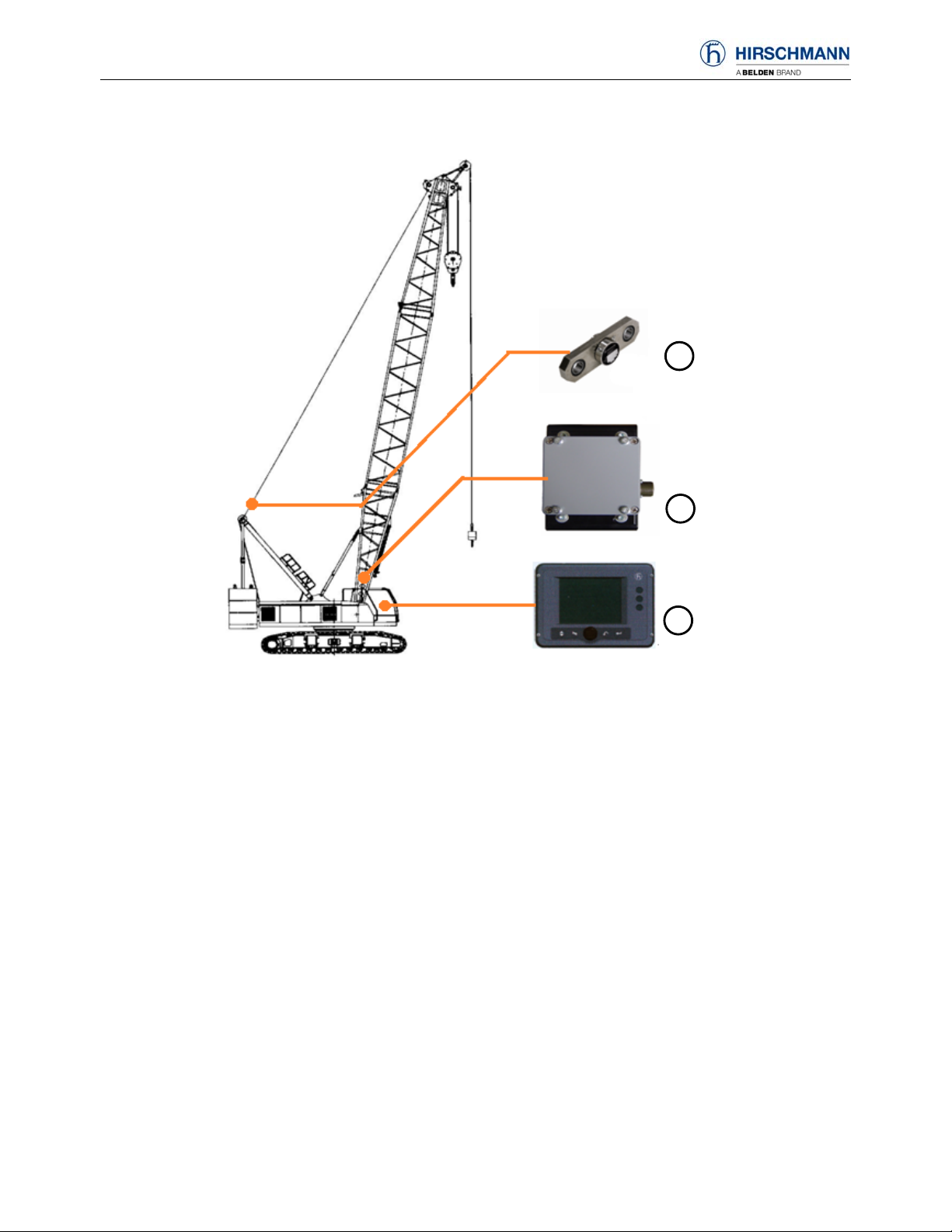
3. SYSTEM DESCRIPTION
3
2
Components of LMI System
Generally, the LMI system consists of
1. HC3901 Controller 1 pc
2. WG103 Angle Sensor 1 pc
3. KMD force Sensor 1 pc
1
3
Page 7

Operator’s Manual
3.1 HC3901 Controller
HC3901 controller uses 16 bit high performance processors and the CANopen communication
technology. It is the safety protector specially designed to meet the required safety standards under the
harsh environment.
Technical data:
Operating temperature: –20°C ~ +70°C.
Operating voltage: 11 ... 36V DC
Operating current: 200mA@24V
Communication interface: 1×CANopen, 1×RS232
Installation: External and horizontal
Display Size: 5.7 inch
Program memory: 2 x 2 MB
Data memory: 2 x 1 MB
Communiacation interface: 1×SAEJ1939,1×CANopen2.0B,2×RS232
Input analog: 6
Input digital: 6
Output digital: 6 (It can be set to PWM output, but it will reduce the no. of output digital.)
Relay output: 1 (max. 5A)
Protection class: IP65
Installation:
When the system is on, it’s forbidden to plug and unplug the cable connecting with the controller.
Before implementing any welding work on the crane body, the operator must take off cables
connecting the controller in order to avoid damage.
This system uses scaffolding installation.
4
Page 8

3.2 WG Angle Sensor
Angle sensor WG accurately measures the boom angle. The high sealed housing keeps the inside
component away from the influence of temperature, humidity etc.
Technical data
Measuring range: 0-90°
Output signal: 4-20mA
Linearity tolerance: <±0.2°
Hysteresis tolerance: <±0.1°
Operating temperature: -25~+70
Storing temperature: -40~+70
Protection class: IP65
Installation
The correct positioning is important for installing angle sensors.
The angle sensors are usually installed along the right side boom, at the inner side of boom base, if
it’s viewed from the boom base to boom tip. (as shown below).
Make sure the horizontal line of sensor is parallel to the horizontal center line of the boom. Adjust the
bolts of the sensor to reduce the angle deviation between actual measured boom angle and displayed
boom angle on the console.
Boom bottom Angle sensor
Horizontal center line
of the boom
Angle Sensor Installation Graph
Angle Senso r Installation Graph
5
Page 9

Operator’s Manual
3.3 Force Sensor
Force sensor KMD is perfectly designed for static and dynamic tensile force measurements.
The sensor stands out for high overload capacity, high fatigue strength, good corrosion resistance
and maintenance-free operation.
Technical data:
Nominal load range: from 1T up to 500T
Charge of measuring body: 200%
Charge of measuring body up to flow limit: 300%
Safe to breaking point: 500%
Linearity: < 0.3% typ.
Hysteresis: < 0.5% typ.
Protection class: IP65
Operating temperature range: -40℃ to +70℃
Installation
KMD force sensor is measuring unit, it should require the conscientious and careful treatment.
Be sure to obtain the fittings and the relative tolerance data suggested by KMD force sensor.
Observe the installation situation to make sure that no elastic parts are used in the force transmission
which might affect the measurements.
The bores in the locking pins must be in alignment.
Make sure force sensor not to bear side force.
KMD Force Sensor Installation Graph
6
Page 10

4. OPERATION AND DISPLAY INTERFACE
1
2
4 33
1.Data display(see 4.1)
2.Indicator light
3.Function keys: from left to right, menu key/buzzer key/back key/confirmation key.(the function keys
have one-to-one relationships with the key symbols on the display.)
4.Rotary button:They can be used to select function items on the display by rotating the button and
confirm the selection by pushing the button.
7
Page 11

Operator’s Manual
4.1 Data display(values are only for example)
2
1
3
4
5
7 8
9
10
11
12
13
21
20
19
1. Height status bar and percentage display
2. Jib angle
3. Jib length
4. Height
5. OM information display
6. Reeving
7. OM code
8. Date and Time
display(year/month/day/hour/minute/second)
9. OM information setting
10. Function setting key symbol
18
17
16 15
14
11. Error code information key symbol
12. Upper and low angle setting
13. Main Hook/ Subhook Switch
14. Wind speed
15. Upper and low angle
16. Rated load weight
17. Actual load weight
18. Boom angle
19. Radius
20. Boom length
21. Error code information
8
Page 12

4.2 EN13000
The yellow icon is force-active warning icon: when the crane is forced to be active, corresponding
warning icon will display on the main interface to remind that the crane is at force-active state now and
LMI will not have corresponding protection function.
LMI override activated
SET-UP mode activated
Main hoist three times protection alarm
Auxiliary hoist three times protection
alarm
SET-UP mode activated alarm
Third hoist three times protection alarm
Derricking in activated
A2B switch on the main hoist alarm
Rope limit override activated
A2B switch on the auxiliary hoist alarm
A2B switch activated
Main Boom luffing angle limit alarm
Slewing limit alarm
9
Page 13

Operator’s Manual
4.3Weight status bar
The weight percentage status bar indicates the relationship between the actual load weight and the
rated load weight during the crane operation and the weight percentage value is subject to the relationship
changes.
Green zone: safe range (weight percentage0-90%)
Yellow zone: pre-warning range (weight percentage 90-100%)
Red zone: over-load warning range (weight percentage exceeding100%)
4.4 Indicator light
Prewarning light
This yellow prewarning light comes up when the load on the machine amounts to more than 90%
of the respective nominal carrying load, which indicates that an overload situation is
immediately pending.
For the operator, this means that the machine work can continue only with the greatest amount of
caution
Overload warning light
This red Overload warning light indicates to the machine operator that an overload condition
has occurred. It lights up when the crane load has reached 100% of maximum load carrying
capacity permitted for the current operating status. The acoustic alarm sounds. The
load-moment-increasing crane movements are switched off at the same time
A2B switch lamp
This red warning light lights up when the heavy bob and spreader of A2B switch meet each
other and are hoisted. In the meanwhile, the buzzer alarms, which indicates the hook block has
arised the height maximum. Combining with the electric system, the crane movements from
hoisting and extending boom to luffing down are stopped. Please check A2B switch before operating the
crane in order to prevent human body and the crane from being injured.
Attention: Since A2B switch signal does not input into LMI system, this A2B switch lamp is used
invalid.
10
Page 14

N
N
5. OPERATION METHOD and PROCESS (only for example)
When controller and console of the system is powered on, the data initialization automatically starts.
This progress cannot be directly observed, but a welcoming display (Logo display) will appear at the
console to present the manufacturer and the initializing status.
The crane drivers shall be very familiar with the operation of LMI system and correctly adjust it
before start to work.
Power on
Self Checking System
Confirm OM
Error or Not?
Is the displayed
OM the same as
the actual one?
Is the showed
Reeve the same
as the actual
Operate the crane to work.
YES
Look up the error code list to solve
O
Choose the same OM by OM
buttons
O
Choose the same Reeving by
Reeving buttons
11
Page 15

Operator’s Manual
5.1 Set OM and Reev
Reeving setting is to set the LMI reeving identical to the actual reeving.Operators shall carefully
adjust the displayed reeving equal to the actual reeving before start to work.
The Reeving must be set equal to the actual reeving, otherwise the LMI may not be able to work properly.
At the main display, select icon by rotary button, press it or confirmation key to enter into
“Set OM and Reev” Display1 as followed:
WARNING
Back to the previous display.
Confirm the select value.
Back to the main display.
In the “Set OM and Reev” Display1, circumgyrate the rotary button, press it or confirmation key to
enter into the “Set OM and Reev” Display2 (Self_assembly OM enter into the main display directly) as
followed:
After selecting OM parameter by pressing and rotating rotary button, press the confirmation key
twice to enter into main interface, then OM setting succeeds. After pressing confirmation key, press turn
back key, which means that setting is cancelled and OM can be reset.
12
Page 16

Two switchable OMs can be selected by default OM option.
5.2 Function Setting
At the main display, select icon by rotate button, press the button or confirmation key to enter
into ”Function Page” as followed:
Back to the previous display.
Confirm the select value.
Back to the main display.
5.2.1 System setting
At the “Function Display”, select “System Set” icon by rotary button, press it or confirmation key to
enter into ”System info” as followed:
Back to the previous display.
Confirm the select value.
Back to the main display.
13
Page 17

Operator’s Manual
Time Setting
Before setting time, the first step is to input the password. If the display shows the wrong time,
please connect with the manufacture first. DO NOT set time yourself.
The setting steps are as followed:
At first, select “Time Set” icon by rotating button at the “Function Display”, press the button or
confirmation key to enter into “Input Password” as the following:
Back to the previous display.
Confirm the select value.
Back to the main display.
At the “Input Password”, the first password “ * ” is showed automatically number “0”. Operator can
select the correct number by rotate button, then press it or confirmation key, the system will transfer to the
second “ * ”.
After inputting four numbers, press the button or confirmation key to enter into “Time Set Display”
as the following:
Back to the previous display.
Confirm the select value.
Back to the main display.
In “Time setting”, when the year number turns blue, select actual year number by rotating button and
press it or confirmation key, the next number will automatically become blue.
After setting all numbers, “Confirm?” will appear on the interface. Press button or confirmation key,
and the “current time” will be modified to the actual time.
14
Page 18

5.2.2 CANbus Status Overview
At the “Function Display”, select “Can Bus” icon by rotary button, press it or confirmation key to
enter into ”CANbus Status Overview Display” as followed:
Back to the previous display.
Confirm the select value.
Back to the main display.
At this display:
If the pane shows green, it means working normally.
If the pane shows yellow, it means preparing.
If the pane shows red, it means error or not-in-use status. At this moment, operators need to check
the system.
5.2.3 I/O Port Inquiry
At the main display, select “port inquiry” icon by rotate button, press the button or confirmation key
to enter into “I/O Port Inquiry Display” as followed:
Back to the previous display.
transfer to Analog Input Port Display
Back to the main display.
This display shows the information of Digital I/O port.The state pane shows green, it means high
level, DIN stands for digital input and DOUT is digital output.
If operators want to inquire analog information, please press menu key which represents icon
and transfer to “Analog Value” as followed:
15
Page 19

Operator’s Manual
Back to the previous display.
Back to the main display.
5.2.4 Load Inquriy
At the “Function Display”, select “Load Chart” icon by rotary button, press it or confirmation button
to enter into the “OM select” display:
Back to the previous display.
Confirm the select value.
Back to the main display.
Select the OM by rotary button, press the confirmation button to enter into the”load chart” display,
as the followed:
Select the BM length by the rotary button, press the confirmation button ,then transfer to the
corresponding load data.
Note: All values in the chart are only for example.
16
Page 20

5.3 Error Code Information
When the system appears malfunction, the error code would appear at the main display.Through the
error code information, crane operators and service engineers can better understand what the error code
stands for, and quickly find out the fault reasons and suggested solutions. (Operators can inquire the error
code by two ways: The error code inquiry in the display and the “troubleshooting” item in the menual.)
At the main display, select icon by rotary button, press the button or confirmation key to
enter into “Fault Help” as followed:
Back to the previous display.
Back to the main display.
Switch to query cause and elimination of different fault by rotarying button.
5.4 Angle Limit Setting
At the main display, select icon by rotary button, press the button or confirmation key to enter
into “Angle Limit Setting” as followed:
Back to the previous display.
Confirm the select value.
Back to the main display.
After the transformer to the maximum(minimum) in the main boom Angle, according to the
confirmed limit Angle value.
17
Page 21

Operator’s Manual
6. SYSTEM FUNCTIONS
6.1 Warning
Under any below conditions, HC3901 LMI system will light up and send out alarm for warning.
The crane is overload
The hook approaching height limitation
System error
6.2 Prohibition
Cooperating with crane electrics system, the LMI system will send alarm warning and any of the
following crane’s movements will be prohibited:
Boom luffing down
Hoisting up
At this moment, only the movements toward safe direction are allowed:
Boom luffing up
Hoisting down
18
Page 22

7 INSPECTION MAINTENANCE AND CONSIDERATIONS
7.1 Inspection before Operation
Check all components of the LMI system to make sure no one damages or breaks off.
Turn the power on and detect whether the display is normal or there is warning, error indication and
so on.
After display works normally, detect whether all the system works normally and whether the main
boom angle, work radius and load display are the same as the actual ones.
7.2 Routine Maintenance
Check the angle transducer as to oil leakage.
Check the insulating layer of all the cables. If the insulating layer or the wire inside damaged, please
replace new one immediately.
Check the cable reel as to sufficient tight or not.
Clean the display regularly to make it clear.
7.3 Routine Consideration
Prevent the central unit (display)、power supply cabin、transducers from severely shake.
Each part of the LMI system including central unit, console, transducers etc had been accurate adjusted
and checked by protection technology before leaving factory. Anyone not be trained professionally is
prohibited from dismantling the housing. Otherwise, the system will probably not work normally because
of humidity and dust getting into the components.
7.4 Buzzer Alarms
The buzzer alarms if the system shows normal without any fault codes after started. At this moment,
exam whether the conjunction between cable and A2B is junction off or short circuit of water-in.
7.5 Angle Sensor Adjustment
Use the angle instrument to measure if the displayed value is the
same when the actual angle is between 0°and 70°. If the
displayed value or radius is not the same with the actual value,
operators should adjust the angle transducer.
Release the three bolts (see the left picture),Slowly turn the
angle transducer till the displayed value accords with the actual
value and then tight the three bolts again.
19
Page 23

Operator’s Manual
8. TROUBLESHOOTING
There are 2 different kinds of errors: system or operation. When an error occurs, this means the system
has a fault. The description and code of errors will appear on the screen.
The following Error Code Table gives a brief description of Error Codes elimination.
The errors showed on the table are part of the possible errors of an LMI system. The Elimination on the
table only gives the operator some basic guidelines of solving the problems. If the errors cannot be
solved by following the instruction in the table, please contact our service team:
Tel: +86-400-887-9936
Fax: +86-516-87793971
Email: infoecs@hirschmann-js.com
Error
Error Cause Elimination
Code
E01
Fallen below radius
range or angle range
exceeded
Fallen below the minimum
radius or gone past the
maximum angle specified in
the respective load chart due
to luffing up the boom too far
E02
Radius range
exceeded or fallen
below angle range
Gone past the maximum
radius or fallen below the
minimum angle specified in
the respective load chart due
to luffing down the boom too
far
E04
Operating mode not
acknowledged or non
permitted slewing
A non existing operating mode
has been selected
zone
E05
Main boom length not
available
A non existing main boom
length has been selected
E06
Radius range
exceeded or fallen
below angle range
with luffing jib
operation
Maximum radius as specified
in the load chart exceeded or
fallen below minimum angle
due to luffing down the luffing
jib too far
E07
Overload relais check
relais = overload active and
CU input 20 = on
relais = no overload and CU
input 20 = off
CAUTION
Luff down the boom to a
radius or angle specified in the
load chart.
Luff up the boom to a radius
or angle specified in the load
chart.
Set the correct operating mode
for the operating state in
question
Set the correct main boom
length for the operating state
in question
Luff the jib to a radius or
angle specified in the load
chart.
check cable to overload relais
and CU input 20
check relais
20
Page 24

Error
Code
E12
E13
E14
E15
E16
E17
Error Cause Elimination
Fallen below lower
limit value in
measuring channel
"force main
boom(MB) right"
Cable between the central unit
and the force transducer
defective or loose. Water
inside the plug of the
transducer
Force transducer defective
Check cable as well as plugs,
replace, if need be
Replace force transducer
Replace sensor unit
Electronic component in the
measuring channel is
defective.
Fallen below lower
limit value in
measuring channel
"force jib right"
Cable between the central unit
and the force transducer
defective or loose. Water
inside the plug of the
transducer
Force transducer defective
Electronic component in the
measuring channel is defective
Check cable as well as plugs,
replace, if need be
Replace force transducer
Replace sensor unit
Fallen below lower
limit value in
measuring channel
"force main boom
left"
Cable between the central unit
and the force transducer
defective or loose. Water
inside the plug of the
transducer
Force transducer defective
Electronic component in the
measuring channel is
defective.
Check cable as well as plugs,
replace, if need be
Replace force transducer
Replace sensor unit
Fallen below lower
limit value in
measuring channel
"angle main boom
foot"
Cable between the central unit
and the angle sensor defective
or loose. Water inside the plug
of the angle sensor
Angle potentiometer defective
Electronic component in the
measuring channel defective.
Check cable as well as plugs,
replace, if need be.
Replace angle sensor
Replace sensor unit
Fallen below lower
limit value in
refer to E15
refer to E15
measuring channel
"angle luffing jib
foot"
Fallen below lower
refer to E14
refer to E14
limit value in
measuring channel
"force luffing jib left"
21
Page 25

Operator’s Manual
Error
Error Cause Elimination
Code
E18
Fallen below lower
limit value in
measuring channel
"MB backstip
pressure"
E19
Fallen below lower
limit value in
measuring channel "
luffing jib backstip
pressure "
E1B
Fallen below lower
limit value in
measuring channel
"angle luffing jib tip"
E1C
Fallen below lower
limit value in
measuring channel
"angle main boom tip"
E1D
Fallen below lower
limit value in
measuring channel
"angle super lift mast"
E22
Upper limit value in
measuring channel
"force main boom
right" has been
exceeded.
E23
Upper limit value in
measuring channel
"force jib right" has
been exceeded.
Cable between the central unit
and the pressure transducer
defective or loose. Water
inside the plug of the
transducer
Force transducer defective
Electronic component in the
measuring channel is
defective.
Cable between the central unit
and the pressure transducer
defective or loose. Water
inside the plug of the
transducer
Force transducer defective
Electronic component in the
measuring channel is
defective.
refer to E15
Cable between the central unit
and the angle sensor defective
or loose. Water inside the plug
of the angle sensor
Angle potentiometer defective
Electronic component in the
measuring channel defective.
Cable between the central unit
and the angle sensor defective
or loose. Water inside the plug
of the angle sensor
Angle potentiometer defective
Electronic component in the
measuring channel defective.
refer to E12
refer to E13
Check cable as well as plugs,
replace, if need be
Replace force transducer
Replace sensor unit
Check cable as well as plugs,
replace, if need be
Replace force transducer
Replace sensor unit
refer to E15
Check cable as well as plugs,
replace, if need be.
Replace angle sensor
Replace sensor unit
Check cable as well as plugs,
replace, if need be.
Replace angle sensor
Replace sensor unit
refer to E12
refer to E13
22
Page 26

Error
Code
E24
E25
E26
E27
E28
E29
E2B
E2C
E2D
Error Cause Elimination
Upper limit value in
measuring channel
refer to E14
refer to E14
"force main boom
left" has been
exceeded.
Upper limit value in
measuring channel
refer to E15
refer to E15
"main boom angle
foot" has been
exceeded.
Upper limit value in
measuring channel
refer to E16
refer to E16
"luffing jib angle
foot" has been
exceeded.
Upper limit value in
measuring channel
refer to E17
refer to E17
"force luffing jib left"
has been exceeded.
Upper limit value in
measuring channel
refer to E18
refer to E18
"MB backstip
pressure " has been
exceeded.
Upper limit value in
measuring channel "
refer to E19
refer to E19
jib backstip pressure "
has been exceeded.
Upper limit value in
measuring channel
refer to E1B
refer to E1B
"jib angle tip" has
been exceeded.
Upper limit value in
measuring channel
refer to E1C
refer to E1C
"main boom angle tip"
has been exceeded.
Upper limit value in
measuring channel
refer to E1D
refer to E1D
"super lift mast angle"
has been exceeded (if
avail.).
23
Page 27

Operator’s Manual
Error
Error Cause Elimination
Code
E37
Error in the logical
program flow
E38
System program and
crane data file do not
match.
E39
System program and
load chart file do not
match
E3A
crane data file and
load chart file do not
match
E43
Error in the
write/read memory,
(RAM)
E51
E52
E56
Error in the crane
data file
Error in load chart
file.
Error in crane data
file.
E57
E60
Error in serial crane
data file.
The number of the
selected File base and
the programmed value
are not identical
E61
Error in the CAN bus
data transfer for all
CAN units
E81
Too large difference
of the boom angles at
tip and base boom (if
avail.)
System program file is
defective
Upload valid system software
Replace central unit
Flash-EPROM defective
The system program in the
LMI does not match to the
programming in the crane data
file
The system program in the
LMI and the programming in
the load chart file do not
match.
Crane type in dat file and load
chart file is different
Write/read memory (RAM) or
central unit defective.
No valid data in the crane
data file.
Flash-EPROM defective
Replace central unit
No valid data in the load chart
file
Flash-EPROM defective
Replace central unit
No valid data in the crane
data file during calibration.
Flash-EPROM defective
Replace central unit
Calibration data file does not
contain valid data.
Flash-EPROM defective
No valid data in the load chart
file
Program the correct base
Base number not programmed
Load chart file wrongly
programmed
Check base programming in
CAN Bus cable between the
central unit and the sensor unit
defective or not connected.
Can bus port in the central unit
defective
Replace the central unit
Replace Can Bus cable
Short circuit in a CAN Bus
cable
The angle as to the horizontal
on the boom head exceeds the
main boom angle by more
Check angle sensor on the
than 5 degrees.
Upload valid system program
file or the valid crane data file
Upload valid system program
file or the valid load chart file
Cange dat file and/or load
chart file
Replace central unit
Upload valid crane data file
Upload valid load chart file
Restore or upload valid crane
data file
Upload calibration data file
Replace central unit
Upload valid load chart file
number (1 for base 1, 2 for
base 2)
the load chart file.
Check the connection between
the central unit and the
sensor units
Check angle sensor on the
boom head.
base boom.
24
Page 28

Error
Code
E82
E83
E84
E85
E88
E89
E94
E98
EAB
EAC
EAD
Error Cause Elimination
Too large difference
of the luffing jib
angles at tip and base
jib.
The angle as to the horizontal
on the jib head exceeds the
luffing jib angle by more than
5 degrees.
Check angle sensor on the jib
head.
Check angle sensor on the jib
base.
Maximum force in the
main boom pendants
exceeded
The force actuating on the
main boom pendants has
exceeded the programmed
Reduce force acting on the
main boom pendants.
value
Wrong rigging
condition.
The selected rigging condition
is not contained in the crane
data file.
Select another rigging
condition
Check the programming in the
crane data file.
Error in the radius
determination
Faulty main boom
position during luffing
jib operation
Faulty positioning of
the jib during
operation with fixed
angle to the main
boom or to a luffing
jib
No data transmits
from central unit to
console
LMI watchdog
activated
The computed radius is too
small (negative deflection)
During luffing jib operation
the main boom is not in the
prescribed angle range
Angle measurement of main
boom defective.
During operation with fixed
jib to the main boom, the jib is
not in the permitted angle
range
Angle measurement of the jib
defective
Can bus defective
The system data transmission
defective
LMI processing time limit
exceeded
Check the programming in the
crane data file.
Luff boom to the permitted
range
Check angle measurement of
the main boom.
Luff the auxiliary jib to the
permitted range
Verify angle measurement of
the auxiliary jib.
Restart system
Check Can bus cable
Reset system
Connect PC terminal and
watch error messages
Short circuit in the
A2B switch circuit
A2B switch circuit
disconnected
No valid A2B switch
status
Short circuit in the A2B
switch
Short circuit in the cable to the
A2B switch
Disconnected cable in the
A2B switch
Disconnected cable to the
A2B switch
Sensor wrong function
CAN bus delay
Replace A2B switch
Replace cable to the A2B
switch
Connect or replace cable in
the A2B switch
Connect or replace cable to
the A2B switch
Replace A2B switch
Replace cable to the A2B
switch
25
Page 29

Operator’s Manual
Error
Error Cause Elimination
Code
EB1
Fallen below lower
limit value in
measuring channel
"rope length on the
winch”
EB2
Upper limit value in
measuring channel "
rope length on the
winch" has been
exceeded.
EB3
Upper limit value in
measuring channel
"hook hight" has been
exceeded.
EDD
Battery empty
EFD
LMB Watchdog extra
time
No rope on the winch
(* only EB1)
calibrate rope length
mount sensor or disable
No sensor for winch
measuring available
rope length not calibrated
calibrate rope length, layer
check parameter in
wrong rope/winch parameters
in data-programming
counter input not deefine in
configuration
change I/O configuration
counter input defective
Rope completely rolled up on
winch (* only EB2)
See EB1
see EB1
No rope length between front
sheave and hook
see EB1
Battery check detected a low
* change battery, after this setup
voltage of the battery
Function needs more than 0,5
Meesage is deactivated
sec to be activated, e.g. write
flash PROM
function in data-programming
data-programming
change Iflex
calibrate rope length
see EB1
of RTC
automatically after processing
26
 Loading...