

Page 1
ADVANCED BASS EFFECTS PROCESSOR
OPERATION MANUAL
Page 2
USAGE AND SAFETY PRECAUTIONS
ADVANCED BASS EFFECTS PROCESSOR
USAGE AND SAFETY PRECAUTIONS
In this manual, symbols are used to highlight warnings and cautions for you to read so that accidents
can be prevented. The meanings of these symbols are as follows:
Please observe the following safety tips and precautions to ensure hazard-free use of the 3000B.
• Power requirements
The 3000B is powered by the supplied AC adapter. To prevent malfunction and safety hazards, do
not use any other kind of AC adapter.
When using the 3000B in an area with a different line voltage, please consult your local ZOOM
distributor about acquiring a proper AC adapter.
• Environment
Avoid using your 3000B in environments where it will be exposed to:
• Extreme temperature
• High humidity or moisture
• Excessive dust or sand
• Excessive vibration or shock
• Handling
Since the 3000B is a precision electronic device, avoid applying excessive force to the switches
and buttons. Also take care not to drop the unit, and do not subject it to shock or excessive
pressure.
• Alterations
Never open the case of the 3000B or attempt to modify the product in any way since this can
result in damage to the unit.
• Connecting cables and input and output jacks
You should always turn off the power to the 3000B and all other equipment before connecting or
disconnecting any cables. Also make sure to disconnect all cables and the AC adapter before
moving the 3000B.
USAGE AND SAFETY PRECAUTIONS
Warning
This symbol indicates explanations about extremely dangerous
matters. If users ignore this symbol and handle the device the wrong
way, serious injury or death could result.
Caution
This symbol indicates explanations about dangerous matters. If
users ignore this symbol and handle the device the wrong way,
bodily injury and damage to the equipment could result.
Warning
Caution
Caution
Caution
Caution
Page 3

ADVANCED BASS EFFECTS PROCESSOR
Usage Precautions
• Electrical interference
For safety considerations, the 3000B has been designed to provide maximum protection against the
emission of electromagnetic radiation from inside the device, and protection from external
interference. However, equipment that is very susceptible to interference or that emits powerful
electromagnetic waves should not be placed near the 3000B, as the possibility of interference cannot
be ruled out entirely.
With any type of digital control device, the 3000B included, electromagnetic interference can cause
malfunctioning and can corrupt or destroy data. Care should be taken to minimize the risk of damage.
• Cleaning
Use a soft, dry cloth to clean the 3000B. If necessary, slightly moisten the cloth. Do not use abrasive
cleanser, wax, or solvents (such as paint thinner or cleaning alcohol), since these may dull the finish or
damage the surface.
Please keep this manual in a convenient place for future reference.
USAGE AND SAFETY PRECAUTIONS
Page 4

CONTENTS
USAGE AND SAFETY PRECAUTIONS*
Introduction •••••••••••••••••••••••••••••••••••••••• 1
Names of Parts•••••••••••••••••••••••••••••••••••• 2
Top Panel View •••••••••••••••••••••••••••••••••••• 2
Rear Panel View
•••••••••••••••••••••••••••••••••••• 2
Getting Connected
•••••••••••••••••••••••••••••••• 3
Before Playing
•••••••••••••••••••••••••••••••••••••• 3
Introducing the 3000B •••••••••••••••••••••••• 4
Terms Used in This Manual ••••••••••••••••••••••• 4
Let's Try Out Some Patches
(Play Mode Operation) ••••••••••••••••••••••• 6
Panel Display in Play Mode ••••••••••••••••••••• 6
Selecting a Patch
••••••••••••••••••••••••••••••••• 7
Adjusting the Master Volume
•••••••••••••••••••• 8
Temporarily Switching Effects Off
(Bypass Function)
•••••••••••••••••••••••••••••••• 9
Temporarily Turning the Sound Off
(Mute Function)
••••••••••••••••••••••••••••••••• 10
Tuning Your Bass Guitar
(Auto tuner Function)
••••••••••••••••••••••••••• 11
Adjusting Standard Pitch of Tuner
(Calibration)
••••••••••••••••••••••••••••••••••••• 12
Adjusting Input Sensitivity/Tone
•••••••••••••••• 13
Using the Metronome Function
•••••••••••••••• 14
Changing the Patch Sound
(Edit Mode Operation) ••••••••••••••••••••••• 15
Switching Between Edit and Play Mode ••••••• 15
Panel Display in Edit Mode
••••••••••••••••••••• 16
Switching Effect Modules On/Off
•••••••••••••• 17
Changing Parameter Settings of Effects
••••••• 18
Storing Patches
•••••••••••••••••••••••••••••••••• 19
Copying a Patch to Another Location
•••••••••• 20
Using the FUNCTION switch •••••••••••••• 21
Selecting the Action of the FUNCTION
Switch
••••••••••••••••••••••••••••••••••••••••••• 21
Manual Mode
•••••••••••••••••••••••••••••••••••• 23
Recording/Playing a Phrase (Hold Delay)
•••••• 24
Delay Time Tap Input
•••••••••••••••••••••••••••• 26
Adjusting Effect Parameters in Real Time
(RTM)
•••••••••••••••••••••••••••••••••••••••••••• 27
Controlling the Volume in Real Time
(Volume RTM)
••••••••••••••••••••••••••••••••••• 30
Returning the 3000B to the Factory Default
Settings
••••••••••••••••••••••••••••••••••••••••••• 32
Using the Remote Pedal •••••••••••••••••••• 33
Names of Parts / Connections ••••••••••••••••• 33
RP01 Names of Parts / Functions
••••••••••••• 33
Control functions (RTM mode)
••••••••••••••••• 34
Control functions (DELAY mode)
••••••••••••••• 34
Using the RP01 for Controlling the RTM
Parameter (RTM Mode)
•••••••••••••••••••••••• 35
Using the RP01 for delay effect control
(DELAY Mode)
•••••••••••••••••••••••••••••••••• 38
Effect Types and Parameters •••••••••••••• 40
COMP (Compressor) Module ••••••••••••••••••• 40
DIST/AMP (Distortion/Amp Simulator)
•••••••• 41
WAH
•••••••••••••••••••••••••••••••••••••••••••••• 43
EQ (Equalizer)
•••••••••••••••••••••••••••••••••••• 45
SYNTH (Bass Synthesizer)
•••••••••••••••••••••• 46
EFFECT
•••••••••••••••••••••••••••••••••••••••••• 48
DLY/REV (Delay/Reverb)
••••••••••••••••••••••••• 51
3000B SPECIFICATIONS •••••••••••••••••••• 53
Troubleshooting ••••••••••••••••••••••••••••••• 54
PRESET PATCH LIST
CONTENTS
ADVANCED BASS EFFECTS PROCESSOR
Page 5
Introduction
Thank you for selecting the ZOOM PLAYER 3000B (hereafter simply called the "3000B").
The 3000B is a bass multi-effect device with the following features:
• 45 built in effects types covering a wide range. Up to 9 effects can be combined in
a patch, letting you easily create your own sound.
• Many special effects designed to enhance a bass guitar performance. DEFRET
makes a normal bass sound like a fretless bass. SLAP achieves slapping sound
from 2-finger playing.
• Built-in bass synthesizer detects bass pitch and controls a sound source to generate
unison phrases and harmonic voices. Unusual auto effects such as TRILL and
SWEEP are also available.
• Hold delay function is separate from individual effects and can store and repeat
phrases of up to 6 seconds duration. The delay time can be conveniently set by
tapping a foot switch.
• User-definable FUNCTION switch operates as a bypass or mute switch and can
also be used as real-time controller, for example to vary effect parameters or
volume during a performance.
• Connecting the optional remote pedal RP01 provides an even more powerful range
of real-time controller functions. Use as pedal wah or pedal pitch shifter is also
possible.
• Input sensitivity and tone can be adjusted to match the instrument characteristics
and the playing venue.
• Built-in metronome function and auto-chromatic tuner enhance practice sessions.
Please take the time to read this manual carefully, so as to get the most
out of your 3000B and to ensure optimum performance and reliability.
1 ●
ADVANCED BASS EFFECTS PROCESSOR
Introduction
Page 6
Names of Parts
● 2
Names of Parts
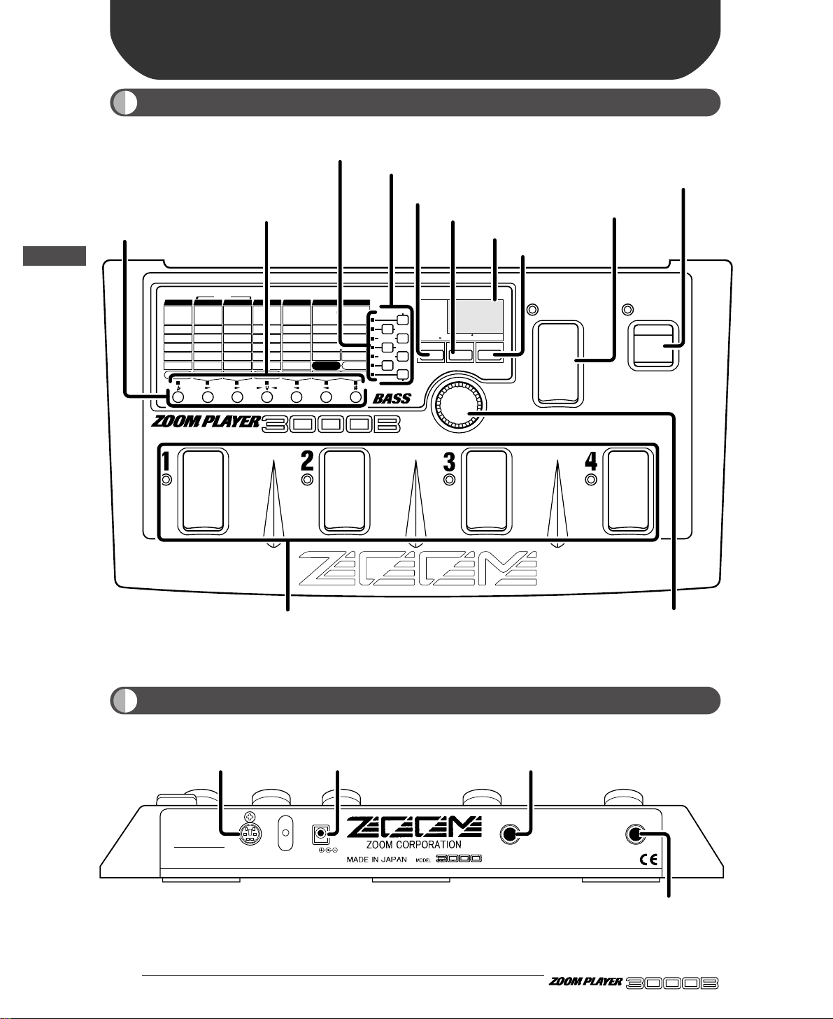
Top Panel View
Rear Panel View
ADVANCED BASS EFFECTS PROCESSOR
BANK
FUNCTION
VALUE
ADVANCED BASS EFFECTS PROCESSOR
1.
COMP2.COMP2
3.LIMITER
4.
DUAL COMP
5.
DEFRET
6.
SLAP
Sens/Sens 1
A
tk
/
Sens 2
P
eak
/
X-F
T
one
/
Bal
Level
VOLUME RTM
G
ain
/
Mid Enh
Level
D.Level
Cabinet
1:DIST-WAH
2:WAH-DIST
DIST
/
AMP RTM
D
pt
/F1/
500Hz
Spd/G1/250Hz
Color/F2/100Hz
Mode/G2/500Hz
Level
WAH RTM
8
kHz
/
High/F1
4
kHz
/
MidF/G1
2
kHz
/
MidG/F2
1kH
z
/
Low/G2
L
evel
ZNR
F
req
/
Mode
Reso/Scale
Decay/Atk
D.Level
Level
SYNTH RTM
C
olor
/
Pit/Dly
Dpt/Sft/Mode
Rate/Tone
Mix/Bal/Reso
FUNCTION Mode
EFFECT RTM
D
lyTime
/
RevTime
FineTime/DlyMix
FB/RevColor
DlyMix/RevMix
Patch Level
DLY/REV RTM
1.CLN1
3.TE-C
5.OD
7.
FN-D
1.
GRAPHIC
2.3-BAND
3.PARAMETRIC
1-6.
BASS SYNTH
7.
HARMO SYNTH
1.DELAY
2.HALL
4.
EARLY REF
5.DLY+REV
3.ROOM
1.CHO
3.PIT
5.
DETUNE
7.
SWEEP
2.FLG
4.P-PIT
6.TRILL
8.RING
2.CLN2
4.SW-C
6.FUZZ
8.AC-D
1.AUTO
3.OCT
5.ENH
7.
GRAPHIC EQ
2.PEDAL
4.
PHASE
6.P-EQ
COMP DIST/AMP WAH EQ SYNTH EFFECT DLY/REV
POSITION
FUNCTION MODE
BANK(VALUE
)
EDIT(CANCEL)GROUP STORE
1.BANK DOWN
2.MANUAL
3.HOLD DLY(LONG)
4.HOLD DLY(REAL)
5.DELAY(TAP)
6.BYPASS
7.MUTE
9.RTM
PRESETUSER
(BOTH)
U
P
U O
MASTER LOW
MASTER MID
INPUT ATT
METRO TEMPO
METRO ON/OFF
METRO VOL
MASTER HIGH
FUNCTION switch
BANK switch
Foot switches 1– 4
Display
EDIT (CANCEL) key
GROUP key
STORE key
Parameter Select keys
Parameter LEDs
VALUE knob
Module LEDs
Module Select keys
300mA
DC9V OUTPUT
(PHONES)
INPUT
REMOTE IN
SERIAL NO.
OUTPUT (PHONES) jack
GUITAR INPUT jack
DC INPUT (AC adapter) jack
REMOTE IN jack
Page 7
Names of Parts
3 ●
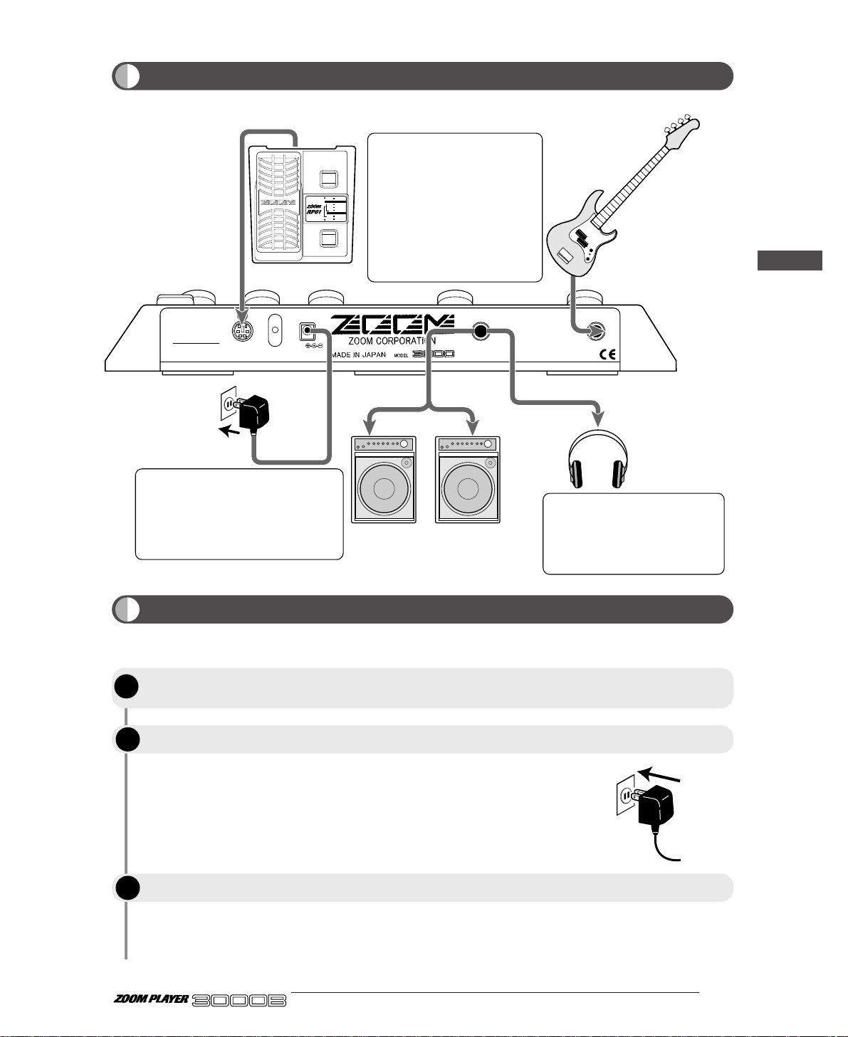
Connect the accessory AC adapter to the DC INPUT jack. The power to
the 3000B is ON when the AC adapter is plugged into a power outlet.
Adjust the volume of the musical instrument and the amplifier while
playing the instrument.
300mA
DC9V OUTPUT
(PHONES)
INPUT
REMOTE IN
SERIAL NO.
PHONES OUT
INPUT
REMOTE IN
OUTPUT
DC INPUT
RP01
PEDAL SW
MODE
SELECT
MONITOR
STATUS
MODE DELECT
PEDAL-WAH ON/OFF(PEDAL SW)
DELAY MODE
(PEDAL SW TRIGGER)
RTM MODE
VOLUME ASSIGN
PEDAL-PITCH ON/OFF(PEDAL SW)
When using the optional remote
pedal RP01, use the remote
cable supplied with the RP01 to
connect the REMOTE OUT
jack of the RP01 to the
REMOTE IN jack of the 3000B.
Power for the remote pedal will
be supplied by the 3000B.
Other remote cables (RC05,
RC10) cannot be used.
A pair of stereo headphones can
be connected to the OUTPUT
(PHONES) jack. If the volume
level from the headphones is low,
use phones with low impedance.
When using the 3000B with one bass
guitar amplifier, make the connection
with a mono cable. For driving two
bass guitar amplifiers, a stereo Y
cable is required. The use of two
amplifiers will result in impressive
wide sound for stereo effects.
Headphones
AC adapter
Bas amplifiers
Bass
Getting Connected
Before Playing
STEP
1
Cut the power to the amplifier, turn the volume down to its minimum level, and
connect the 3000B correctly to the musical instrument and amplifier
Power up the 3000B.
Switch ON the power to the amplifier.
ADVANCED BASS EFFECTS PROCESSOR
After completing connection, the volume has to be adjusted according to the following procedure.
STEP
STEP
2
3
Page 8
Some important concepts are explained in this section.
■ Effect module
An effect module is a single effect that influences the sound in a certain way, similar to a stand-alone
compact effect device such as a compressor or a delay. The 3000B incorporates seven effect modules
which can be used all together or in various combinations.
The following effect modules are incorporated in the 3000B:
• COMP (Compressor)
• DIST/AMP (Distortion/Amp Simulator)
• WAH (Wah)
• EQ (Equalizer)
• SYNTH (Bass Synthesizer)
• EFFECT (Effect)
• DLY/REV (Delay/Reverb)
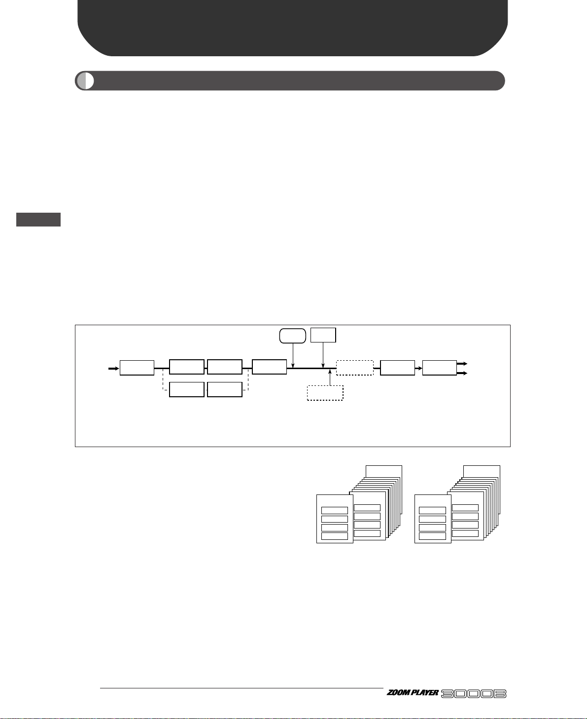
The following diagram shows the signal flow in the effect modules of the 3000B.
■ Patches, groups, and banks
Internal settings for the 3000B can be stored in
memory and retrieved from memory in units called
"patches". A patch contains a maximum of seven
effect modules, each with its selected settings.
Patches are stored in two distinct groups: the USER
group for patches that can be freely altered by the
user, and the PRESET group for patches that are read-only. Each group has room for 40 patches,
resulting in a total memory capacity for 80 patches.
Patches are called up in sets of four, corresponding to the four large foot switches on the top panel of the
3000B. Such a set of four patches is called a "bank". The USER group and the PRESET group each have
ten banks, numbered from 0 through 9.
■ Effect types and parameters
Each effect module of the 3000B has several variations, called "effect types". At any given time, one
effect type is selected for an effect module.
● 4
Introducing the 3000B
Terms Used in This Manual
ADVANCED BASS EFFECTS PROCESSOR
Introducing the 3000B
BANK 9
USER group
PATCH 1
PATCH 2
PATCH 3
PATCH 4
BANK 1
PATCH 1
PATCH 2
PATCH 3
PATCH 4
BANK 0
PATCH 1
PATCH 2
PATCH 3
PATCH 4
BANK 9
PRESET group
PATCH 1
PATCH 2
PATCH 3
PATCH 4
BANK 1
PATCH 1
PATCH 2
PATCH 3
PATCH 4
BANK 0
PATCH 1
PATCH 2
PATCH 3
PATCH 4
COMP
DIST/AMP WAH EQ
WAH DIST/AMP
*1
The position of the DIST/AMP effect module and WAH
*1
effect module can be reversed.
*2
ZNR is a noise reduction system developed by Zoom.
*2
ZNR
SYNTH
*4
MASTER EQ
*3
VOLUME
Using the optional remote pedal RP01, the volume
*3
can be controlled at this point with the pedal.
MASTER EQ is an equalizer that can be set
*4
independently from the individual patches.
EFFECT DLY/REV OUTPUTINPUT
Page 9
Introducing the 3000B
5 ●
The detailed settings that determine the sound are called "parameters". The 3000B has three different
kinds of parameters:
The effect types and effect parameters available for a given effect module are indicated on the panel of
the 3000B.
■ Mode
Operation of the 3000B can be divided into five different states, called "modes". These modes are listed
below.
• Play mode
•••••••• In this mode, you select patches and use the effects for playing your instrument.
In Play mode, you can also temporarily switch effects off, and you can use the auto tuner function.
• Manual mode
••••• In this mode, you can switch effect modules on and off individually, using the
top panel switches of the 3000B. This is also suitable for use during a performance.
• Edit mode
•••••••• In this mode, the effect parameters of the currently selected patch can be edited
(changed) by the user. This allows you to create your own patches.
• Store mode
••••••• This mode serves for storing patches in memory and for copying patches from
one location in memory to another.
• Special mode
••••• This mode serves for initializing the 3000B. USER group settings and patches
can be selectively returned to the factory default.
■ RTM
The 3000B incorporates a so-called RTM (real-time modulation) function which lets the user change
effect parameters or volume in real time, using the FUNCTION switch or the optional remote pedal
RP01. This makes it possible to adjust for example overdrive distortion or reverb mix during a
performance, creating a wide expression range. The parameters to be affected by RTM and the range of
the change can be set for each patch individually.
ADVANCED BASS EFFECTS PROCESSOR
1.
COMP2.COMP2
3.LIMITER
4.
DUAL COMP
5.
DEFRET
6.
SLAP
Sens/Sens 1
A
tk
/
Sens 2
P
eak
/
X-F
T
one
/
Bal
Level
VOLUME RTM
G
ain
/
Mid Enh
Level
D.Level
Cabinet
1:DIST-WAH
2:WAH-DIST
DIST
/
AMP RTM
D
pt
/F1/
500Hz
Spd/G1/250Hz
Color/F2/100Hz
Mode/G2/500Hz
Level
WAH RTM
8
kHz
/
High/F1
4
kHz
/
MidF/G1
2
kHz
/
MidG/F2
1kH
z
/
Low/G2
L
evel
ZNR
F
req
/
Mode
Reso/Scale
Decay/Atk
D.Level
Level
SYNTH RTM
C
olor
/
Pit/Dly
Dpt/Sft/Mode
Rate/Tone
Mix/Bal/Reso
FUNCTION Mode
EFFECT RTM
D
lyTime
/
RevTime
FineTime/DlyMix
FB/RevColor
DlyMix/RevMix
Patch Level
DLY/REV RTM
1.CLN1
3.TE-C
5.OD
7.
FN-D
1.
GRAPHIC
2.3-BAND
3.PARAMETRIC
1-6.
BASS SYNTH
7.
HARMO SYNTH
1.DELAY
2.HALL
4.
EARLY REF
5.DLY+REV
3.ROOM
1.CHO
3.PIT
5.
DETUNE
7.
SWEEP
2.FLG
4.P-PIT
6.TRILL
8.RING
2.CLN2
4.SW-C
6.FUZZ
8.AC-D
1.AUTO
3.OCT
5.ENH
7.
GRAPHIC EQ
2.PEDAL
4.
PHASE
6.P-EQ
COMP DIST/AMP WAH EQ SYNTH EFFECT DLY/REV
POSITION
Effect modules
Effect types
Parameters
1– 6
Global parameterPatch parameterEffect parameters
• Effect parameter
Determines the effect intensity or signal flow in an
effect module. Effect parameter settings are stored
as part of each patch.
• Patch parameter
Determines the overall level of a patch, Zoom
Noise Reduction (ZNR) settings, and other aspects
affecting the entire patch. Patch parameters are
stored as part of each patch.
• Global parameter
This kind of parameter affects all patches in the
same way. For example, the FUNCTION Mode
parameter that determines how the FUNCTION
switch works is a global parameter. This setting is
retained also when switching patches, until the unit
is turned off. When wishing to preserve the global
parameter setting, any patch of the USER group
should be selected and stored before turning the
unit off.
Page 10
The Play mode is for selecting a patch and playing. When you power up the 3000B, it automatically
activates in Play mode, and the USER group's Bank 0, Patch Number 1 is selected.
In Play mode, the display LEDs on the panel show the following information:
(1) Group
The type of group currently selected is indicated in the left side of the display.
(2) Bank Number
The currently selected bank number is indicated in the right side of the display.
(3) Patch Number
The LED of the Foot Switch 1 - 4 corresponding to the currently selected patch number lights up.
(4) Effect Module ON/OFF
The panel module LEDs light for the effect modules that are on in the currently selected patch.
● 6
Let's Try Out Some Patches
(Play Mode Operation)
Panel Display in Play Mode
ADVANCED BASS EFFECTS PROCESSOR
Let's Try Out Some Patches (Play Mode Operation)
BANK
FUN
VALUE
ADVANCED BASS EFFECTS PROCESSOR
1.
COMP2.COMP2
3.LIMITER
4.
DUAL COMP
5.
DEFRET
6.
SLAP
Sens/Sens 1
A
tk
/
Sens 2
P
eak
/
X-F
T
one
/
Bal
Level
VOLUME RTM
G
ain
/
Mid Enh
Level
D.Level
Cabinet
1:DIST-WAH
2:WAH-DIST
DIST
/
AMP RTM
D
pt
/F1/
500Hz
Spd/G1/250Hz
Color/F2/100Hz
Mode/G2/500Hz
Level
WAH RTM
8
kHz
/
High/F1
4
kHz
/
MidF/G1
2
kHz
/
MidG/F2
1kH
z
/
Low/G2
L
evel
ZNR
F
req
/
Mode
Reso/Scale
Decay/Atk
D.Level
Level
SYNTH RTM
C
olor
/
Pit/Dly
Dpt/Sft/Mode
Rate/Tone
Mix/Bal/Reso
FUNCTION Mode
EFFECT RTM
D
lyTime
/
RevTime
FineTime/DlyMix
FB/RevColor
DlyMix/RevMix
Patch Level
DLY/REV RTM
1.CLN1
3.TE-C
5.OD
7.
FN-D
1.
GRAPHIC
2.3-BAND
3.PARAMETRIC
1-6.
BASS SYNTH
7.
HARMO SYNTH
1.DELAY
2.HALL
4.
EARLY REF
5.DLY+REV
3.ROOM
1.CHO
3.PIT
5.
DETUNE
7.
SWEEP
2.FLG
4.P-PIT
6.TRILL
8.RING
2.CLN2
4.SW-C
6.FUZZ
8.AC-D
1.AUTO
3.OCT
5.ENH
7.
GRAPHIC EQ
2.PEDAL
4.
PHASE
6.P-EQ
COMP DIST/AMP WAH EQ SYNTH EFFECT DLY/REV
POSITION
FUNCTION MODE
BANK(VALUE
)
EDIT(CANCEL)GROUP STORE
1.BANK DOWN
2.MANUAL
3.HOLD DLY(LONG)
4.HOLD DLY(REAL)
5.DELAY(TAP)
6.BYPASS
7.MUTE
9.RTM
PRESETUSER
(BOTH)
U
P
U O
MASTER LOW
MASTER MID
INPUT ATT
METRO TEMPO
METRO ON/OFF
METRO VOL
MASTER HIGH
(1) (2)
(4)
(3)
Page 11
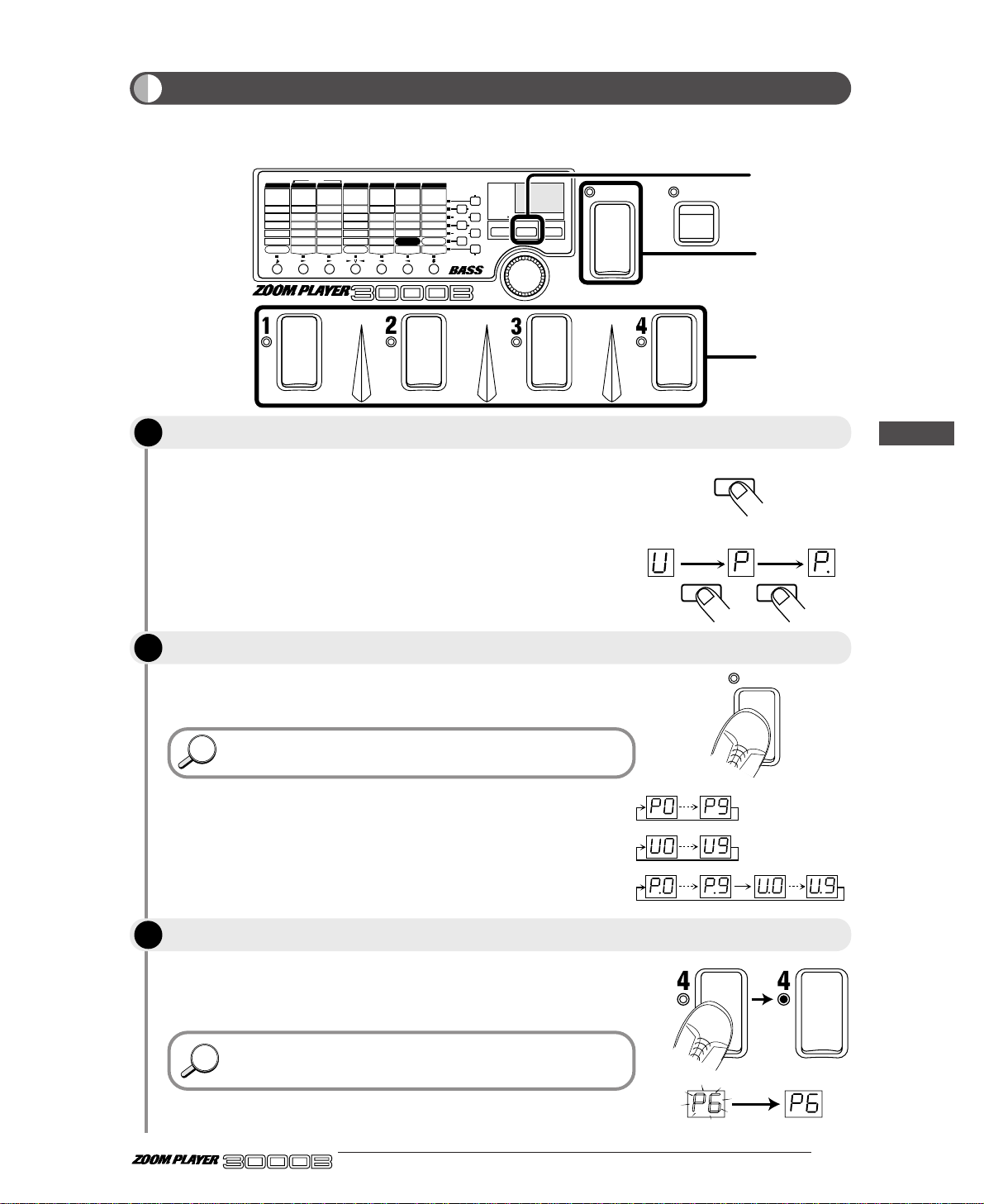
When choosing a patch, first decide which group of patches you want
to use. With each push of the GROUP key, the left side of the display
changes in the following sequence.
• U (USER) Only USER group patches can be used.
• P (PRESET) Only PRESET group patches can be used.
• U. or P. (BOTH) Patches of both USER and PRESET
groups can be used.
Each time you step, you change to the next higher bank number. (The
bank number flashes.)
In this status, the patch will not yet be changed
The LEDs lights for the Foot Switch you stepped on, telling you that a
patch has been selected. Also, the indicated bank number changes
from flashing to constantly lit.
Here, try switching the patches while you are actually playing
your instrument, and find out what types of patches are stored in
the 3000B.
HINTHINT
HINTHINT
GROUP
BANK
GROUP=PRESET
GROUP=BOTH
GROUP=USER
USER PRESET BOTH
GROUP GROUP
In the Play mode, you can play by choosing one of the patches from among the 80 types (40 USER group
patches plus 40 PRESET patches) in memory.
7 ●
BANK
FUNCTION
VALUE
ADVANCED BASS EFFECTS PROCESSOR
1.
COMP2.COMP2
3.LIMITER
4.
DUAL COMP
5.
DEFRET
6.
SLAP
Sens/Sens 1
A
tk
/
Sens 2
P
eak
/
X-F
T
one
/
Bal
Level
VOLUME RTM
G
ain
/
Mid Enh
Level
D.Level
Cabinet
1:DIST-WAH
2:WAH-DIST
DIST
/
AMP RTM
D
pt
/F1/
500Hz
Spd/G1/250Hz
Color/F2/100Hz
Mode/G2/500Hz
Level
WAH RTM
8
kHz
/
High/F1
4
kHz
/
MidF/G1
2
kHz
/
MidG/F2
1kH
z
/
Low/G2
L
evel
ZNR
F
req
/
Mode
Reso/Scale
Decay/Atk
D.Level
Level
SYNTH RTM
C
olor
/
Pit/Dly
Dpt/Sft/Mode
Rate/Tone
Mix/Bal/Reso
FUNCTION Mode
EFFECT RTM
D
lyTime
/
RevTime
FineTime/DlyMix
FB/RevColor
DlyMix/RevMix
Patch Level
DLY/REV RTM
1.CLN1
3.TE-C
5.OD
7.
FN-D
1.
GRAPHIC
2.3-BAND
3.PARAMETRIC
1-6.
BASS SYNTH
7.
HARMO SYNTH
1.DELAY
2.HALL
4.
EARLY REF
5.DLY+REV
3.ROOM
1.CHO
3.PIT
5.
DETUNE
7.
SWEEP
2.FLG
4.P-PIT
6.TRILL
8.RING
2.CLN2
4.SW-C
6.FUZZ
8.AC-D
1.AUTO
3.OCT
5.ENH
7.
GRAPHIC EQ
2.PEDAL
4.
PHASE
6.P-EQ
COMP DIST/AMP WAH EQ SYNTH EFFECT DLY/REV
POSITION
FUNCTION MODE
BANK(VALUE
)
EDIT(CANCEL)GROUP STORE
1.BANK DOWN
2.MANUAL
3.HOLD DLY(LONG)
4.HOLD DLY(REAL)
5.DELAY(TAP)
6.BYPASS
7.MUTE
9.RTM
PRESETUSER
(BOTH)
U
P
U O
MASTER LOW
MASTER MID
INPUT ATT
METRO TEMPO
METRO ON/OFF
METRO VOL
MASTER HIGH
1
2
3
Selecting a Patch
Press the GROUP key to select the group.
Press the GROUP key to select the group.
Step on a Foot Switch (1 – 4) to select a patch.
ADVANCED BASS EFFECTS PROCESSOR
Let's Try Out Some Patches (Play Mode Operation)
STEP
1
STEP
2
STEP
3
Page 12
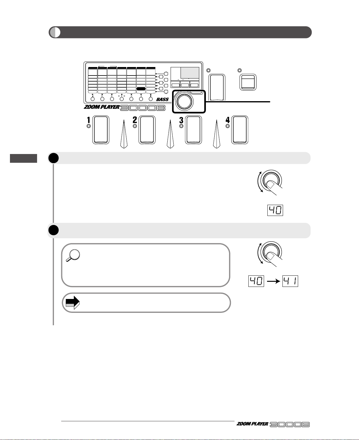
The display will indicate the current value (1 - 50) of the Master Volume
for one second (default setting: 40).
• The Master Volume setting works in common for all patches. It
cannot be stored for separate patches.
• If you want to change the volume for specific patches, adjust the
patch level in Edit mode. For details, see page 52
• Master volume can also be adjusted in Manual mode ( → page
23).
The master level setting cannot be stored. It needs to be adjusted
every time the unit is turned on.
NOTE
● 8
ADVANCED BASS EFFECTS PROCESSOR
In Play mode, regardless of the selectable patches, the final output volume by the 3000B can be
controlled by the Master Volume.
HINTHINT
BANK
FUNCTION
VALUE
ADVANCED BASS EFFECTS PROCESSOR
1.
COMP2.COMP2
3.LIMITER
4.
DUAL COMP
5.
DEFRET
6.
SLAP
Sens/Sens 1
A
tk
/
Sens 2
P
eak
/
X-F
T
one
/
Bal
Level
VOLUME RTM
G
ain
/
Mid Enh
Level
D.Level
Cabinet
1:DIST-WAH
2:WAH-DIST
DIST
/
AMP RTM
D
pt
/F1/
500Hz
Spd/G1/250Hz
Color/F2/100Hz
Mode/G2/500Hz
Level
WAH RTM
8
kHz
/
High/F1
4
kHz
/
MidF/G1
2
kHz
/
MidG/F2
1kH
z
/
Low/G2
L
evel
ZNR
F
req
/
Mode
Reso/Scale
Decay/Atk
D.Level
Level
SYNTH RTM
C
olor
/
Pit/Dly
Dpt/Sft/Mode
Rate/Tone
Mix/Bal/Reso
FUNCTION Mode
EFFECT RTM
D
lyTime
/
RevTime
FineTime/DlyMix
FB/RevColor
DlyMix/RevMix
Patch Level
DLY/REV RTM
1.CLN1
3.TE-C
5.OD
7.
FN-D
1.
GRAPHIC
2.3-BAND
3.PARAMETRIC
1-6.
BASS SYNTH
7.
HARMO SYNTH
1.DELAY
2.HALL
4.
EARLY REF
5.DLY+REV
3.ROOM
1.CHO
3.PIT
5.
DETUNE
7.
SWEEP
2.FLG
4.P-PIT
6.TRILL
8.RING
2.CLN2
4.SW-C
6.FUZZ
8.AC-D
1.AUTO
3.OCT
5.ENH
7.
GRAPHIC EQ
2.PEDAL
4.
PHASE
6.P-EQ
COMP DIST/AMP WAH EQ SYNTH EFFECT DLY/REV
POSITION
FUNCTION MODE
BANK(VALUE
)
EDIT(CANCEL)GROUP STORE
1.BANK DOWN
2.MANUAL
3.HOLD DLY(LONG)
4.HOLD DLY(REAL)
5.DELAY(TAP)
6.BYPASS
7.MUTE
9.RTM
PRESETUSER
(BOTH)
U
P
U O
MASTER LOW
MASTER MID
INPUT ATT
METRO TEMPO
METRO ON/OFF
METRO VOL
MASTER HIGH
1, 2
VALUE
VALUE
Adjusting the Master Volume
Operate the VALUE knob.
While the value is displayed, use the VALUE knob to adjust the volume to the
desired level.
Let's Try Out Some Patches (Play Mode Operation)
STEP
STEP
1
2
Page 13
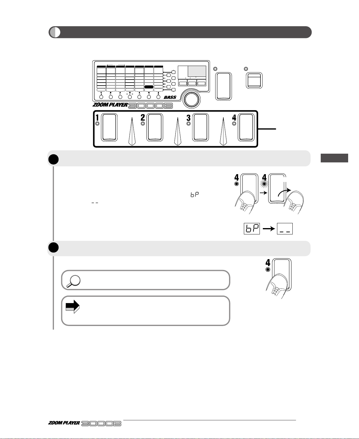
If you lightly step on the Foot Switch and then release your foot within a
second, the 3000B will enter the Bypass status. The LED for the
currently selected patch will flash, and the module LED will light. Also,
the display will indicate the Bypass status
with " ", and then
change to " ".
The 3000B will return to the usual Play mode.
The FUNCTION switch can also be used to activate the Bypass
function. For details, please refer to page 21.
When the FUNCTION switch mode is set to bypass or mute, step 1
is invalid. When not wishing to use the Foot Switches 1 - 4 for
on/off switching of the bypass or mute condition, set the
FUNCTION switch mode to BYPASS or MUTE.
NOTE
HINTHINT
You can switch the 3000B Effect mode OFF temporarily (this is called "bypass"), and monitor the
instrument's direct sound. This is a handy function for checking how the effects are working.
9 ●
BANK
FUNCTION
VALUE
ADVANCED BASS EFFECTS PROCESSOR
1.
COMP2.COMP2
3.LIMITER
4.
DUAL COMP
5.
DEFRET
6.
SLAP
Sens/Sens 1
A
tk
/
Sens 2
P
eak
/
X-F
T
one
/
Bal
Level
VOLUME RTM
G
ain
/
Mid Enh
Level
D.Level
Cabinet
1:DIST-WAH
2:WAH-DIST
DIST
/
AMP RTM
D
pt
/F1/
500Hz
Spd/G1/250Hz
Color/F2/100Hz
Mode/G2/500Hz
Level
WAH RTM
8
kHz
/
High/F1
4
kHz
/
MidF/G1
2
kHz
/
MidG/F2
1kH
z
/
Low/G2
L
evel
ZNR
F
req
/
Mode
Reso/Scale
Decay/Atk
D.Level
Level
SYNTH RTM
C
olor
/
Pit/Dly
Dpt/Sft/Mode
Rate/Tone
Mix/Bal/Reso
FUNCTION Mode
EFFECT RTM
D
lyTime
/
RevTime
FineTime/DlyMix
FB/RevColor
DlyMix/RevMix
Patch Level
DLY/REV RTM
1.CLN1
3.TE-C
5.OD
7.
FN-D
1.
GRAPHIC
2.3-BAND
3.PARAMETRIC
1-6.
BASS SYNTH
7.
HARMO SYNTH
1.DELAY
2.HALL
4.
EARLY REF
5.DLY+REV
3.ROOM
1.CHO
3.PIT
5.
DETUNE
7.
SWEEP
2.FLG
4.P-PIT
6.TRILL
8.RING
2.CLN2
4.SW-C
6.FUZZ
8.AC-D
1.AUTO
3.OCT
5.ENH
7.
GRAPHIC EQ
2.PEDAL
4.
PHASE
6.P-EQ
COMP DIST/AMP WAH EQ SYNTH EFFECT DLY/REV
POSITION
FUNCTION MODE
BANK(VALUE
)
EDIT(CANCEL)GROUP STORE
1.BANK DOWN
2.MANUAL
3.HOLD DLY(LONG)
4.HOLD DLY(REAL)
5.DELAY(TAP)
6.BYPASS
7.MUTE
9.RTM
PRESETUSER
(BOTH)
U
P
U O
MASTER LOW
MASTER MID
INPUT ATT
METRO TEMPO
METRO ON/OFF
METRO VOL
MASTER HIGH
1, 2
Release your foot
straight away
Temporarily Switching Effects Off (Bypass Function)
Step on the Foot Switch for the currently selected patch number (the Foot Switch
whose LED is lit) and release your foot straight away.
To release this status, lightly step on and release your foot from the Foot Switch
again, or select another patch.
ADVANCED BASS EFFECTS PROCESSOR
Let's Try Out Some Patches (Play Mode Operation)
STEP
1
STEP
2
Page 14
● 10
ADVANCED BASS EFFECTS PROCESSOR
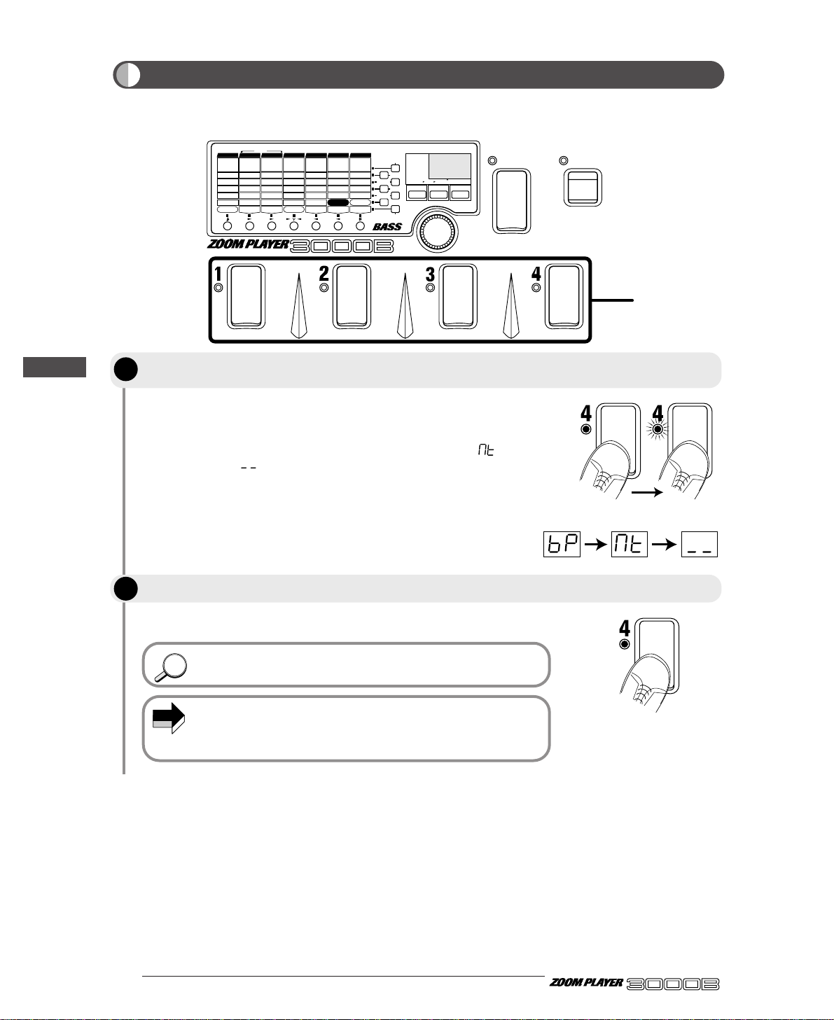
The mute function temporarily turns the output OFF.
If you have stepped for more than a second on the Foot Switch whose
LED is lit, both effect sound and direct sound will be silenced (muted).
The LED for the currently selected patch will flash, and the module LED
will light. Also, the display will indicate the Mute status with
"", and
then change to " ".
The 3000B will return to the usual Play mode.
The FUNCTION switch can also be used to activate the Mute
function. For details, please refer to page 21.
When the FUNCTION switch mode is set to bypass or mute, step 1
is invalid. When not wishing to use the Foot Switches 1 - 4 for
on/off switching of the bypass or mute condition, set the
FUNCTION switch mode to BYPASS or MUTE.
NOTE
HINTHINT
BANK
FUNCTION
VALUE
ADVANCED BASS EFFECTS PROCESSOR
1.
COMP2.COMP2
3.LIMITER
4.
DUAL COMP
5.
DEFRET
6.
SLAP
Sens/Sens 1
A
tk
/
Sens 2
P
eak
/
X-F
T
one
/
Bal
Level
VOLUME RTM
G
ain
/
Mid Enh
Level
D.Level
Cabinet
1:DIST-WAH
2:WAH-DIST
DIST
/
AMP RTM
D
pt
/F1/
500Hz
Spd/G1/250Hz
Color/F2/100Hz
Mode/G2/500Hz
Level
WAH RTM
8
kHz
/
High/F1
4
kHz
/
MidF/G1
2
kHz
/
MidG/F2
1kH
z
/
Low/G2
L
evel
ZNR
F
req
/
Mode
Reso/Scale
Decay/Atk
D.Level
Level
SYNTH RTM
C
olor
/
Pit/Dly
Dpt/Sft/Mode
Rate/Tone
Mix/Bal/Reso
FUNCTION Mode
EFFECT RTM
D
lyTime
/
RevTime
FineTime/DlyMix
FB/RevColor
DlyMix/RevMix
Patch Level
DLY/REV RTM
1.CLN1
3.TE-C
5.OD
7.
FN-D
1.
GRAPHIC
2.3-BAND
3.PARAMETRIC
1-6.
BASS SYNTH
7.
HARMO SYNTH
1.DELAY
2.HALL
4.
EARLY REF
5.DLY+REV
3.ROOM
1.CHO
3.PIT
5.
DETUNE
7.
SWEEP
2.FLG
4.P-PIT
6.TRILL
8.RING
2.CLN2
4.SW-C
6.FUZZ
8.AC-D
1.AUTO
3.OCT
5.ENH
7.
GRAPHIC EQ
2.PEDAL
4.
PHASE
6.P-EQ
COMP DIST/AMP WAH EQ SYNTH EFFECT DLY/REV
POSITION
FUNCTION MODE
BANK(VALUE
)
EDIT(CANCEL)GROUP STORE
1.BANK DOWN
2.MANUAL
3.HOLD DLY(LONG)
4.HOLD DLY(REAL)
5.DELAY(TAP)
6.BYPASS
7.MUTE
9.RTM
PRESETUSER
(BOTH)
U
P
U O
MASTER LOW
MASTER MID
INPUT ATT
METRO TEMPO
METRO ON/OFF
METRO VOL
MASTER HIGH
1, 2
Keep your foot more than
one second
Temporarily Turning the Sound Off (Mute Function)
Step on the Foot Switch whose LED is currently lit, keep your foot pressed on the
switch for a moment, and then release it.
To release this status, step on the Foot Switch again, or select another patch.
Let's Try Out Some Patches (Play Mode Operation)
STEP
STEP
1
2
Page 15
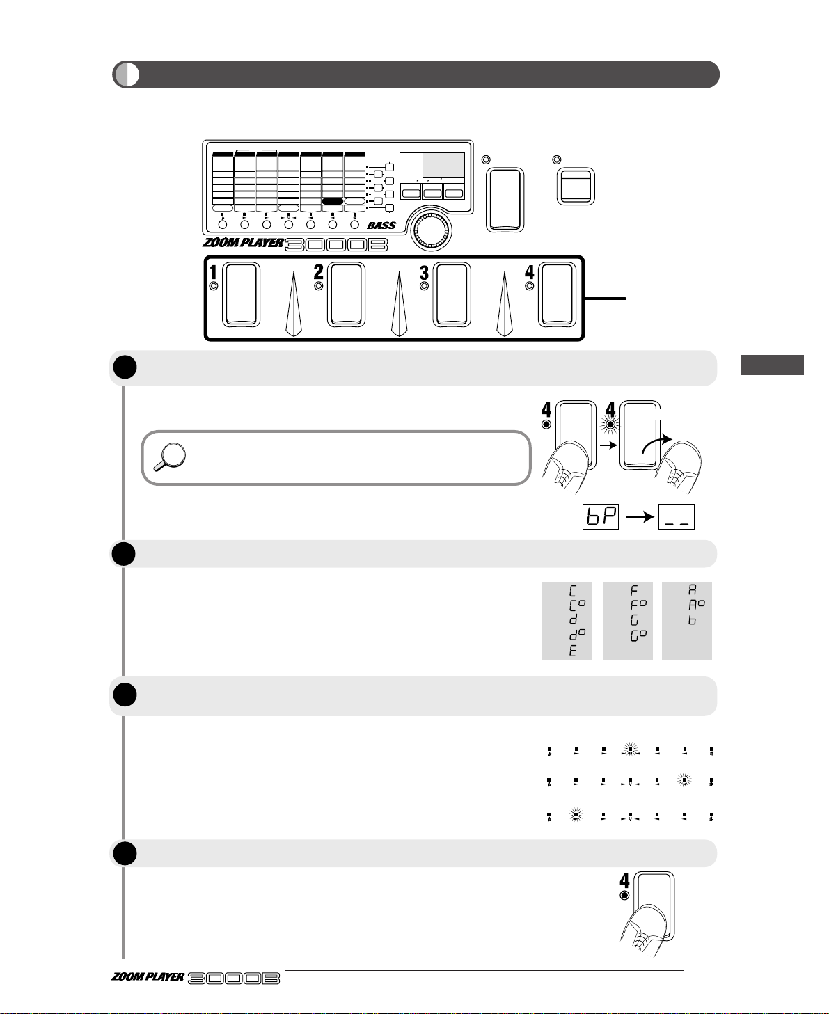
The 3000B will enter the Bypass status, and you can use the auto tuner
function. The display changes from "
bP
" to "__".
The auto tuner function can be used when the 3000B is in Mute
status. This is handy for tuning on stage when you do not want to
produce the sound externally.
The display shows the note closest to the current pitch. Tune the bass
guitar until it matches the desired note.
When the tuner function is ON, the module LEDs work as a tuning
meter. When the pitch matches accurately, the center LED is lit.
HINTHINT
The 3000B incorporates a chromatic auto tuner function. This function can be used in the Bypass or Mute
condition.
11 ●
BANK
FUNCTION
VALUE
ADVANCED BASS EFFECTS PROCESSOR
1.
COMP2.COMP2
3.LIMITER
4.
DUAL COMP
5.
DEFRET
6.
SLAP
Sens/Sens 1
A
tk
/
Sens 2
P
eak
/
X-F
T
one
/
Bal
Level
VOLUME RTM
G
ain
/
Mid Enh
Level
D.Level
Cabinet
1:DIST-WAH
2:WAH-DIST
DIST
/
AMP RTM
D
pt
/F1/
500Hz
Spd/G1/250Hz
Color/F2/100Hz
Mode/G2/500Hz
Level
WAH RTM
8
kHz
/
High/F1
4
kHz
/
MidF/G1
2
kHz
/
MidG/F2
1kH
z
/
Low/G2
L
evel
ZNR
F
req
/
Mode
Reso/Scale
Decay/Atk
D.Level
Level
SYNTH RTM
C
olor
/
Pit/Dly
Dpt/Sft/Mode
Rate/Tone
Mix/Bal/Reso
FUNCTION Mode
EFFECT RTM
D
lyTime
/
RevTime
FineTime/DlyMix
FB/RevColor
DlyMix/RevMix
Patch Level
DLY/REV RTM
1.CLN1
3.TE-C
5.OD
7.
FN-D
1.
GRAPHIC
2.3-BAND
3.PARAMETRIC
1-6.
BASS SYNTH
7.
HARMO SYNTH
1.DELAY
2.HALL
4.
EARLY REF
5.DLY+REV
3.ROOM
1.CHO
3.PIT
5.
DETUNE
7.
SWEEP
2.FLG
4.P-PIT
6.TRILL
8.RING
2.CLN2
4.SW-C
6.FUZZ
8.AC-D
1.AUTO
3.OCT
5.ENH
7.
GRAPHIC EQ
2.PEDAL
4.
PHASE
6.P-EQ
COMP DIST/AMP WAH EQ SYNTH EFFECT DLY/REV
POSITION
FUNCTION MODE
BANK(VALUE
)
EDIT(CANCEL)GROUP STORE
1.BANK DOWN
2.MANUAL
3.HOLD DLY(LONG)
4.HOLD DLY(REAL)
5.DELAY(TAP)
6.BYPASS
7.MUTE
9.RTM
PRESETUSER
(BOTH)
U
P
U O
MASTER LOW
MASTER MID
INPUT ATT
METRO TEMPO
METRO ON/OFF
METRO VOL
MASTER HIGH
1, 2
C=
C
#
=
D=
D
#
=
E=
F=
F
#
=
G=
G
#
=
A=
A
#
=
B=
Release your foot
straight away
Pitch matches accurately
Pitch is sharp
Pitch is flat
Tuning Your Bass Guitar (Auto tuner Function)
Lightly step on the foot switch whose LED is currently lit in the display for Foot
Switches 1 - 4, and release your foot straight away.
Pick the string you want to tune
When the display shows the desired note, perform fine adjustment until the
center module LED (EQ module LED) lights up.
Press the Foot Switch 1 - 4 again. The 3000B reverts to Play mode.
ADVANCED BASS EFFECTS PROCESSOR
Let's Try Out Some Patches (Play Mode Operation)
STEP
1
STEP
2
STEP
3
STEP
4
Page 16
● 12
ADVANCED BASS EFFECTS PROCESSOR
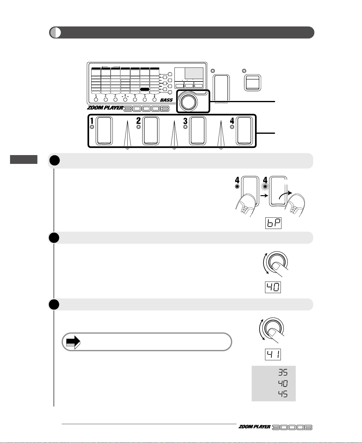
This function sets the reference pitch used by the tuner of the 3000B.
The display will indicate "bP", and the module LEDs will light.
The display will indicate the current calibration value for one second.
Calibration is within the range of "35" (A = 435 Hz) and "45" (A = 445
Hz).
Every time the unit is turned on, the calibration value is reset to
A = 440 Hz.
NOTE
BANK
FUNCTION
VALUE
ADVANCED BASS EFFECTS PROCESSOR
1.
COMP2.COMP2
3.LIMITER
4.
DUAL COMP
5.
DEFRET
6.
SLAP
Sens/Sens 1
A
tk
/
Sens 2
P
eak
/
X-F
T
one
/
Bal
Level
VOLUME RTM
G
ain
/
Mid Enh
Level
D.Level
Cabinet
1:DIST-WAH
2:WAH-DIST
DIST
/
AMP RTM
D
pt
/F1/
500Hz
Spd/G1/250Hz
Color/F2/100Hz
Mode/G2/500Hz
Level
WAH RTM
8
kHz
/
High/F1
4
kHz
/
MidF/G1
2
kHz
/
MidG/F2
1kH
z
/
Low/G2
L
evel
ZNR
F
req
/
Mode
Reso/Scale
Decay/Atk
D.Level
Level
SYNTH RTM
C
olor
/
Pit/Dly
Dpt/Sft/Mode
Rate/Tone
Mix/Bal/Reso
FUNCTION Mode
EFFECT RTM
D
lyTime
/
RevTime
FineTime/DlyMix
FB/RevColor
DlyMix/RevMix
Patch Level
DLY/REV RTM
1.CLN1
3.TE-C
5.OD
7.
FN-D
1.
GRAPHIC
2.3-BAND
3.PARAMETRIC
1-6.
BASS SYNTH
7.
HARMO SYNTH
1.DELAY
2.HALL
4.
EARLY REF
5.DLY+REV
3.ROOM
1.CHO
3.PIT
5.
DETUNE
7.
SWEEP
2.FLG
4.P-PIT
6.TRILL
8.RING
2.CLN2
4.SW-C
6.FUZZ
8.AC-D
1.AUTO
3.OCT
5.ENH
7.
GRAPHIC EQ
2.PEDAL
4.
PHASE
6.P-EQ
COMP DIST/AMP WAH EQ SYNTH EFFECT DLY/REV
POSITION
FUNCTION MODE
BANK(VALUE
)
EDIT(CANCEL)GROUP STORE
1.BANK DOWN
2.MANUAL
3.HOLD DLY(LONG)
4.HOLD DLY(REAL)
5.DELAY(TAP)
6.BYPASS
7.MUTE
9.RTM
PRESETUSER
(BOTH)
U
P
U O
MASTER LOW
MASTER MID
INPUT ATT
METRO TEMPO
METRO ON/OFF
METRO VOL
MASTER HIGH
1
2, 3
VALUE
VALUE
435Hz :
440Hz :
445Hz :
Release your foot
straight away
Adjusting Standard Pitch of Tuner (Calibration)
Invoke the Bypass status by lightly stepping on and releasing your foot from the
Foot Switch whose LED is currently lit in the display for Foot Switches 1 - 4.
Operate the VALUE knob.
While the value is displayed, use the VALUE knob to set the desired value.
Let's Try Out Some Patches (Play Mode Operation)
STEP
STEP
STEP
1
2
3
Page 17
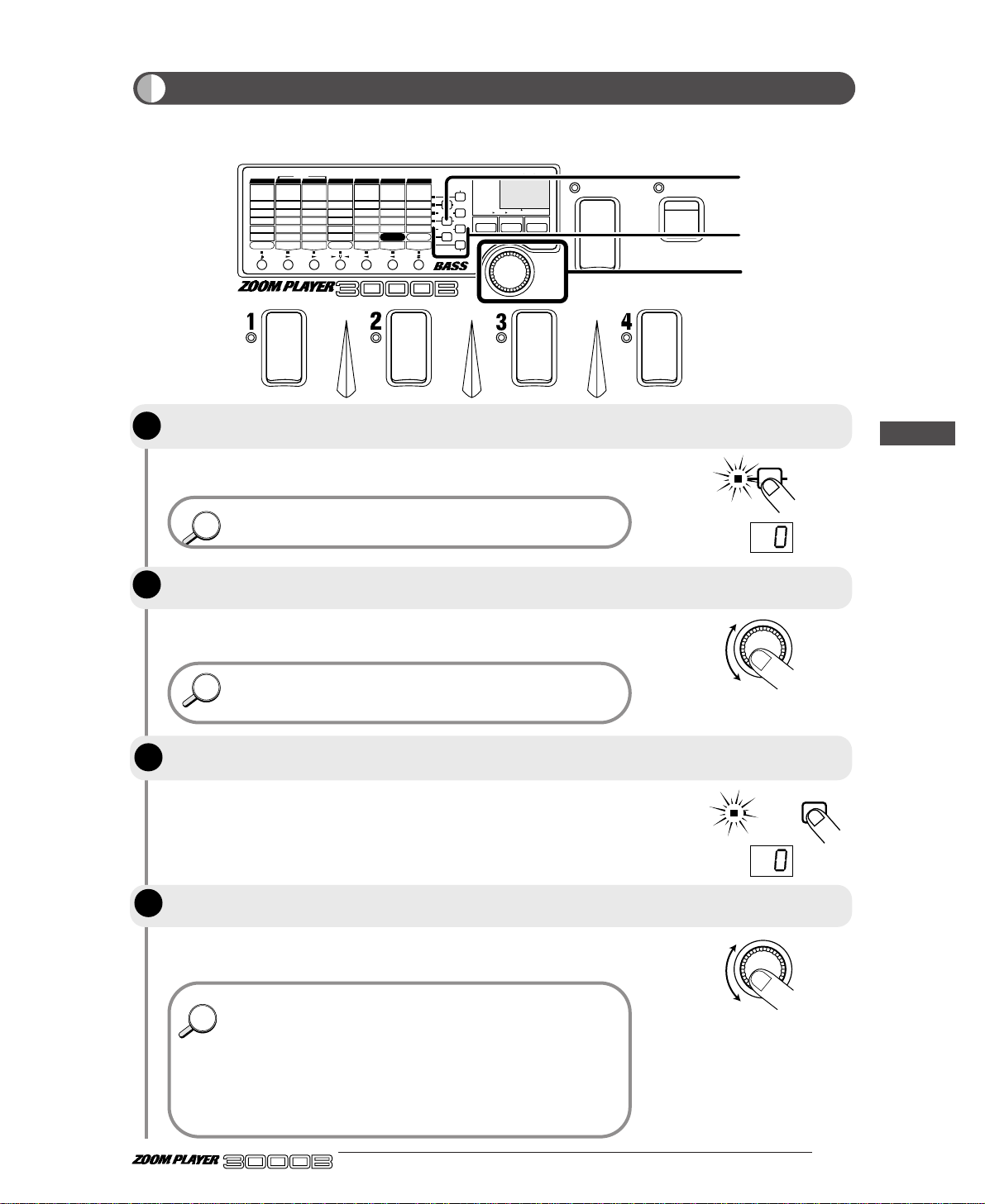
The current input attenuator setting (-18 to 0) is shown on the display
for about one second.
When the 3000B is in Play mode, the Parameter Select keys serve
to change internal settings of the 3000B or to use the metronome.
Pressing the same Parameter Select key once more returns the unit to
the previous mode.
When a bass guitar with high output is connected, the sound of the
3000B may be distorted due to input overload. In such a case,
reduce the input sensitivity.
These keys serve to adjust the high range, midrange, and low range,
respectively. The current setting (-12 to 0 to +12) is shown on the
display for about one second.
Pressing the same Parameter Select key once more returns the unit to
the previous mode.
• The input sensitivity and tone settings are valid for all patches,
and are maintained also when the unit is switched off.
• The input sensitivity and tone adjustment can be performed also
in Manual mode (page 23).
• In Play mode and Manual mode, if the INPUT ATT, MASTER
HIGH, MASTER MID, or MASTER LOW setting is other than 0,
the respective LED is lit.
• In the Bypass state, the input sensitivity setting is active, but
tone adjustment settings are inactive.
HINTHINT
HINTHINT
HINTHINT
This section describes how to adjust input sensitivity (for matching the 3000B to the output level of the
instrument) and tone (to suit the acoustic requirements of a performance venue).
13 ●
BANK
FUNCTION
VALUE
ADVANCED BASS EFFECTS PROCESSOR
1.
COMP2.COMP2
3.LIMITER
4.
DUAL COMP
5.
DEFRET
6.
SLAP
Sens/Sens 1
A
tk
/
Sens 2
P
eak
/
X-F
T
one
/
Bal
Level
VOLUME RTM
G
ain
/
Mid Enh
Level
D.Level
Cabinet
1:DIST-WAH
2:WAH-DIST
DIST
/
AMP RTM
D
pt
/F1/
500Hz
Spd/G1/250Hz
Color/F2/100Hz
Mode/G2/500Hz
Level
WAH RTM
8
kHz
/
High/F1
4
kHz
/
MidF/G1
2
kHz
/
MidG/F2
1kH
z
/
Low/G2
L
evel
ZNR
F
req
/
Mode
Reso/Scale
Decay/Atk
D.Level
Level
SYNTH RTM
C
olor
/
Pit/Dly
Dpt/Sft/Mode
Rate/Tone
Mix/Bal/Reso
FUNCTION Mode
EFFECT RTM
D
lyTime
/
RevTime
FineTime/DlyMix
FB/RevColor
DlyMix/RevMix
Patch Level
DLY/REV RTM
1.CLN1
3.TE-C
5.OD
7.
FN-D
1.
GRAPHIC
2.3-BAND
3.PARAMETRIC
1-6.
BASS SYNTH
7.
HARMO SYNTH
1.DELAY
2.HALL
4.
EARLY REF
5.DLY+REV
3.ROOM
1.CHO
3.PIT
5.
DETUNE
7.
SWEEP
2.FLG
4.P-PIT
6.TRILL
8.RING
2.CLN2
4.SW-C
6.FUZZ
8.AC-D
1.AUTO
3.OCT
5.ENH
7.
GRAPHIC EQ
2.PEDAL
4.
PHASE
6.P-EQ
COMP DIST/AMP WAH EQ SYNTH EFFECT DLY/REV
POSITION
FUNCTION MODE
BANK(VALUE
)
EDIT(CANCEL)GROUP STORE
1.BANK DOWN
2.MANUAL
3.HOLD DLY(LONG)
4.HOLD DLY(REAL)
5.DELAY(TAP)
6.BYPASS
7.MUTE
9.RTM
PRESETUSER
(BOTH)
U
P
U O
MASTER LOW
MASTER MID
INPUT ATT
METRO TEMPO
METRO ON/OFF
METRO VOL
MASTER HIGH
1
2, 4
3
INPUT ATT
MASTER HIGH
To adjust input sensitivity, press the Parameter Select key marked INPUT ATT in
Play mode or Manual mode.
Adjust the VALUE knob while playing your instrument, to adjust the input
sensitivity.
To adjust tone, press one of the Parameter Select keys marked MASTER HIGH,
MASTER MID, or MASTER LOW.
Adjust the VALUE knob to change the attenuation or boost of the selected
frequency range.
ADVANCED BASS EFFECTS PROCESSOR
Adjusting Input Sensitivity/Tone
Let's Try Out Some Patches (Play Mode Operation)
STEP
1
STEP
2
STEP
3
VALUE
STEP
4
VALUE
Page 18
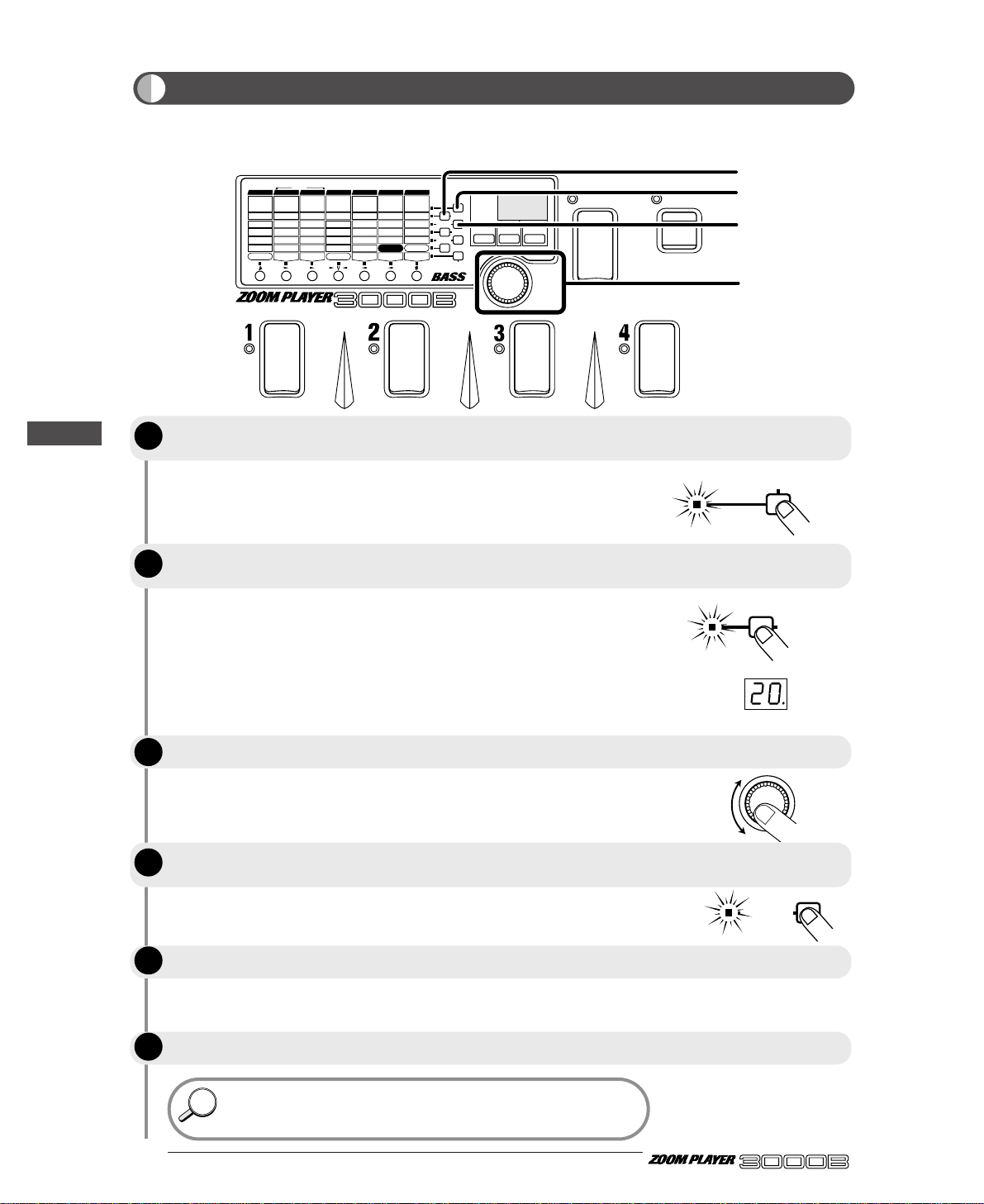
The metronome comes on and a click sound is heard. The LED of the
METRO ON/OFF key flashes in the metronome tempo.
The current tempo setting (40 - 250) is shown on the display for about
one second. Values between 100 and 199 are denoted by a dot in the
right column. Values between 200 and 250 are denoted by dots in the
left and right columns.
Tempo value: 40 ... 99 100 101 ... 199 200 201 ...
Display indication: 40 ... 99 00. 01. ... 99. 0.0. 0.1. ...
Pressing the same Parameter Select key once more returns the unit to
the previous mode.
The current volume setting (0 - 50) is shown on the display.
Pressing the same Parameter Select key once more returns the unit to
the previous mode.
• The tempo and volume settings are maintained also when the unit is
switched off.
• The metronome function can be used also in Manual mode (page 23).
HINTHINT
● 14
ADVANCED BASS EFFECTS PROCESSOR
The 3000B incorporates a metronome function that is handy for scale and fingering practice. The
metronome can be used at any time in Play mode, Manual mode, and in the Bypass state.
BANK
FUNCTION
VALUE
ADVANCED BASS EFFECTS PROCESSOR
1.
COMP2.COMP2
3.LIMITER
4.
DUAL COMP
5.
DEFRET
6.
SLAP
Sens/Sens 1
A
tk
/
Sens 2
P
eak
/
X-F
T
one
/
Bal
Level
VOLUME RTM
G
ain
/
Mid Enh
Level
D.Level
Cabinet
1:DIST-WAH
2:WAH-DIST
DIST
/
AMP RTM
D
pt
/F1/
500Hz
Spd/G1/250Hz
Color/F2/100Hz
Mode/G2/500Hz
Level
WAH RTM
8
kHz
/
High/F1
4
kHz
/
MidF/G1
2
kHz
/
MidG/F2
1kH
z
/
Low/G2
L
evel
ZNR
F
req
/
Mode
Reso/Scale
Decay/Atk
D.Level
Level
SYNTH RTM
C
olor
/
Pit/Dly
Dpt/Sft/Mode
Rate/Tone
Mix/Bal/Reso
FUNCTION Mode
EFFECT RTM
D
lyTime
/
RevTime
FineTime/DlyMix
FB/RevColor
DlyMix/RevMix
Patch Level
DLY/REV RTM
1.CLN1
3.TE-C
5.OD
7.
FN-D
1.
GRAPHIC
2.3-BAND
3.PARAMETRIC
1-6.
BASS SYNTH
7.
HARMO SYNTH
1.DELAY
2.HALL
4.
EARLY REF
5.DLY+REV
3.ROOM
1.CHO
3.PIT
5.
DETUNE
7.
SWEEP
2.FLG
4.P-PIT
6.TRILL
8.RING
2.CLN2
4.SW-C
6.FUZZ
8.AC-D
1.AUTO
3.OCT
5.ENH
7.
GRAPHIC EQ
2.PEDAL
4.
PHASE
6.P-EQ
COMP DIST/AMP WAH EQ SYNTH EFFECT DLY/REV
POSITION
FUNCTION MODE
BANK(VALUE
)
EDIT(CANCEL)GROUP STORE
1.BANK DOWN
2.MANUAL
3.HOLD DLY(LONG)
4.HOLD DLY(REAL)
5.DELAY(TAP)
6.BYPASS
7.MUTE
9.RTM
PRESETUSER
(BOTH)
U
P
U O
MASTER LOW
MASTER MID
INPUT ATT
METRO TEMPO
METRO ON/OFF
METRO VOL
MASTER HIGH
2
3, 5
4
1, 6
Using the Metronome Function
To activate the metronome, press the Parameter Select key marked METRO
ON/OFF in Play mode, Manual mode, or in the Bypass state.
To change the metronome tempo, press the Parameter Select key marked
METRO TEMPO.
Use the VALUE knob to adjust the tempo.
To change the metronome volume, press the Parameter Select key marked
METRO VOL.
Use the VALUE knob to adjust the volume.
To turn the metronome off, press the METRO ON/OFF key once more.
Let's Try Out Some Patches (Play Mode Operation)
STEP
STEP
STEP
STEP
1
2
3
4
METRO ON/OFF
METRO TEMPO
VALUE
STEP
STEP
5
6
METRO VOL
Page 19

The 3000B enters Edit mode, so that you can edit parameters.
The editing methods are explained in detail on the following pages.
The 3000B returns to the Play mode.
15 ●
BANK
FUNCTION
VALUE
ADVANCED BASS EFFECTS PROCESSOR
1.
COMP2.COMP2
3.LIMITER
4.
DUAL COMP
5.
DEFRET
6.
SLAP
Sens/Sens 1
A
tk
/
Sens 2
P
eak
/
X-F
T
one
/
Bal
Level
VOLUME RTM
G
ain
/
Mid Enh
Level
D.Level
Cabinet
1:DIST-WAH
2:WAH-DIST
DIST
/
AMP RTM
D
pt
/F1/
500Hz
Spd/G1/250Hz
Color/F2/100Hz
Mode/G2/500Hz
Level
WAH RTM
8
kHz
/
High/F1
4
kHz
/
MidF/G1
2
kHz
/
MidG/F2
1kH
z
/
Low/G2
L
evel
ZNR
F
req
/
Mode
Reso/Scale
Decay/Atk
D.Level
Level
SYNTH RTM
C
olor
/
Pit/Dly
Dpt/Sft/Mode
Rate/Tone
Mix/Bal/Reso
FUNCTION Mode
EFFECT RTM
D
lyTime
/
RevTime
FineTime/DlyMix
FB/RevColor
DlyMix/RevMix
Patch Level
DLY/REV RTM
1.CLN1
3.TE-C
5.OD
7.
FN-D
1.
GRAPHIC
2.3-BAND
3.PARAMETRIC
1-6.
BASS SYNTH
7.
HARMO SYNTH
1.DELAY
2.HALL
4.
EARLY REF
5.DLY+REV
3.ROOM
1.CHO
3.PIT
5.
DETUNE
7.
SWEEP
2.FLG
4.P-PIT
6.TRILL
8.RING
2.CLN2
4.SW-C
6.FUZZ
8.AC-D
1.AUTO
3.OCT
5.ENH
7.
GRAPHIC EQ
2.PEDAL
4.
PHASE
6.P-EQ
COMP DIST/AMP WAH EQ SYNTH EFFECT DLY/REV
POSITION
FUNCTION MODE
BANK(VALUE
)
EDIT(CANCEL)GROUP STORE
1.BANK DOWN
2.MANUAL
3.HOLD DLY(LONG)
4.HOLD DLY(REAL)
5.DELAY(TAP)
6.BYPASS
7.MUTE
9.RTM
PRESETUSER
(BOTH)
U
P
U O
MASTER LOW
MASTER MID
INPUT ATT
METRO TEMPO
METRO ON/OFF
METRO VOL
MASTER HIGH
2, 4
Switching Between Edit and Play Mode
ADVANCED BASS EFFECTS PROCESSOR
Changing the Patch Sound (Edit Mode Operation)
In the Play mode, choose the patch you want to edit. (This can be from the USER
or PRESET group.)
Press the EDIT key.
Perform editing.
When you have finished editing, press the EDIT key again.
Changing the Patch Sound(Edit Mode Operation)
This section describes basic operation of the Edit mode. The patches of the 3000B are made up from a
variety of effect parameters that determine the sound and the signal routing, as well as patch parameters
that affect the entire patch such as the ZNR sensitivity setting and the overall patch level. In the Edit
mode, these parameters can be changed to fit your personal preferences. Global parameters are also set in
this mode.
STEP
STEP
1
2
STEP
3
STEP
4
)
EDIT(CANCEL
)
EDIT(CANCEL
Page 20

Changing the Patch Sound (Edit Mode Operation)
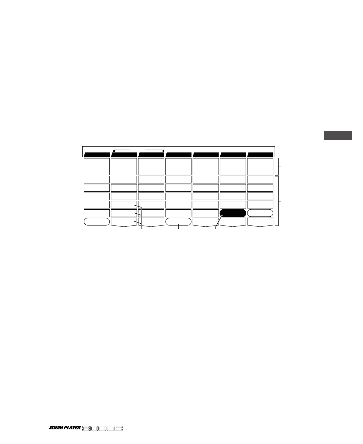
In Edit mode, the panel displays the following information:
(1) Effect module ON/OFF
When the effect modules are ON in a patch, their corresponding module LEDs light.
(2) Parameter type
On the top panel of the 3000B, effect modules are arranged horizontally and effect parameters for the
various modules are listed vertically (including patch parameters and global parameters).
(3) Currently selected parameter
The parameter at the point where the lines marked by the flashing module LED and flashing
parameter LED cross is the parameter that is currently selected for editing. When an effect module is
selected that is currently off, the flashing interval of the module LED changes (the off time becomes
longer).
(4) Parameter value
The value of the parameter currently selected for editing is displayed. When the selected effect
module is off, only "
--" is displayed.
Depending on the type selected for the effect module, some parameters may have no setting item. When
such a parameter is selected, the display shows "
-.-.". For information on effect types and parameters.
● 16
Panel Display in Edit Mode
ADVANCED BASS EFFECTS PROCESSOR
1.
COMP2.COMP2
3.LIMITER
4.
DUAL COMP
5.
DEFRET
6.
SLAP
Sens/Sens 1
A
tk
/
Sens 2
P
eak
/
X-F
Tone/Bal
Level
VOLUME RTM
G
ain
/
Mid Enh
Level
D.Level
Cabinet
1:DIST-WAH
2:WAH-DIST
DIST/AMP RTM
D
pt
/F1/
500Hz
Spd/G1/250Hz
Color/F2/100Hz
Mode/G2/500Hz
Level
WAH RTM
8
kHz
/
High/F1
4kHz/MidF/G1
2
kHz
/
MidG/F2
1kHz/Low/G2
L
evel
ZNR
F
req
/
Mode
Reso/Scale
Decay/Atk
D.Level
Level
SYNTH RTM
C
olor
/
Pit/Dly
Dpt/Sft/Mode
Rate/Tone
Mix/Bal/Reso
FUNCTION Mode
EFFECT RTM
D
lyTime
/
RevTime
FineTime/DlyMix
FB/RevColor
DlyMix/RevMix
Patch Level
DLY/REV RTM
1.CLN1
3.TE-C
5.OD
7.
FN-D
1.
GRAPHIC
2.3-BAND
3.PARAMETRIC
1-6.
BASS SYNTH
7.
HARMO SYNTH
1.DELAY
2.HALL
4.
EARLY REF
5.DLY+REV
3.ROOM
1.CHO
3.PIT
5.
DETUNE
7.
SWEEP
2.FLG
4.P-PIT
6.TRILL
8.RING
2.CLN2
4.SW-C
6.FUZZ
8.AC-D
1.AUTO
3.OCT
5.ENH
7.
GRAPHIC EQ
2.PEDAL
4.
PHASE
6.P-EQ
COMP DIST/AMP WAH E Q SYNTH EFFECT DLY/REV
POSITION
FUNCTION MODE
BANK(VALUE
)
EDIT(CANCEL)GROUP STORE
1.BANK DOWN
2.MANUAL
3.HOLD DLY(LONG)
4.HOLD DLY(REAL)
5.DELAY(TAP)
6.BYPASS
7.MUTE
9.RTM
PRESETUSER
(BOTH)
U
P
1 O
MASTER LOW
MASTER MID
INPUT ATT
METRO TEMPO
METRO ON/OFF
METRO VOL
MASTER HIGH
Dpt/Sft/Mode
Dpt/Sft/Mode
(3)
(1)
(2)
(4)
Bal/Mix/Peak
Mi
Peath L
l
Bal/Mix/Peak
Mi
Peath L
l
Parameters for modules that are
switched off cannot be edited.
NOTE
SERI/PARA
EFFECT2 RTM
SEAMLESS
DELAY RTM
x
eve
FUNCTION Mode
REVERB RTM
Effect module on (LED lit)
SERI/PARA
EFFECT2 RTM
SEAMLESS
DELAY RTM
x
eve
FUNCTION Mode
REVERB RTM
Effect module off (LED out)
When selected effect module is on
/
olor
Shift/Mode
SERI/PARA
EFFECT2 RTM
C
Dpt/Sft/Mode
Rate/Tone
Mix/Bal/Reso
FUNCTION Mode
EFFECT RTM
Selected
parameter
Pitch/Key/Depth
Fine/Scale/Rate
Bal/Mix/Peak
Effect module on
- 2
Parameter value
Pit/Dly
/
lyTime
RevTime
D
FineTime/DlyMix
FB/RevColor
DlyMix/RevMix
Patch Level
DLY/REV RTM
Effect module off
When selected effect module is off
/
lyTime
RevTime
D
FineTime/DlyMix
FB/RevColor
DlyMix/RevMix
Patch Level
DLY/REV RTM
Flashes at
same rate
Selected
parameter
Pitch/Key/Depth
Fine/Scale/Rate
Shift/Mode
Bal/Mix/Peak
SERI/PARA
EFFECT2 RTM
Color/Pit/Dly
Dpt/Sft/Mode
Rate/Tone
Mix/Bal/Reso
FUNCTION Mode
EFFECT RTM
- -
Flashes
OFF interval is
longer
Page 21

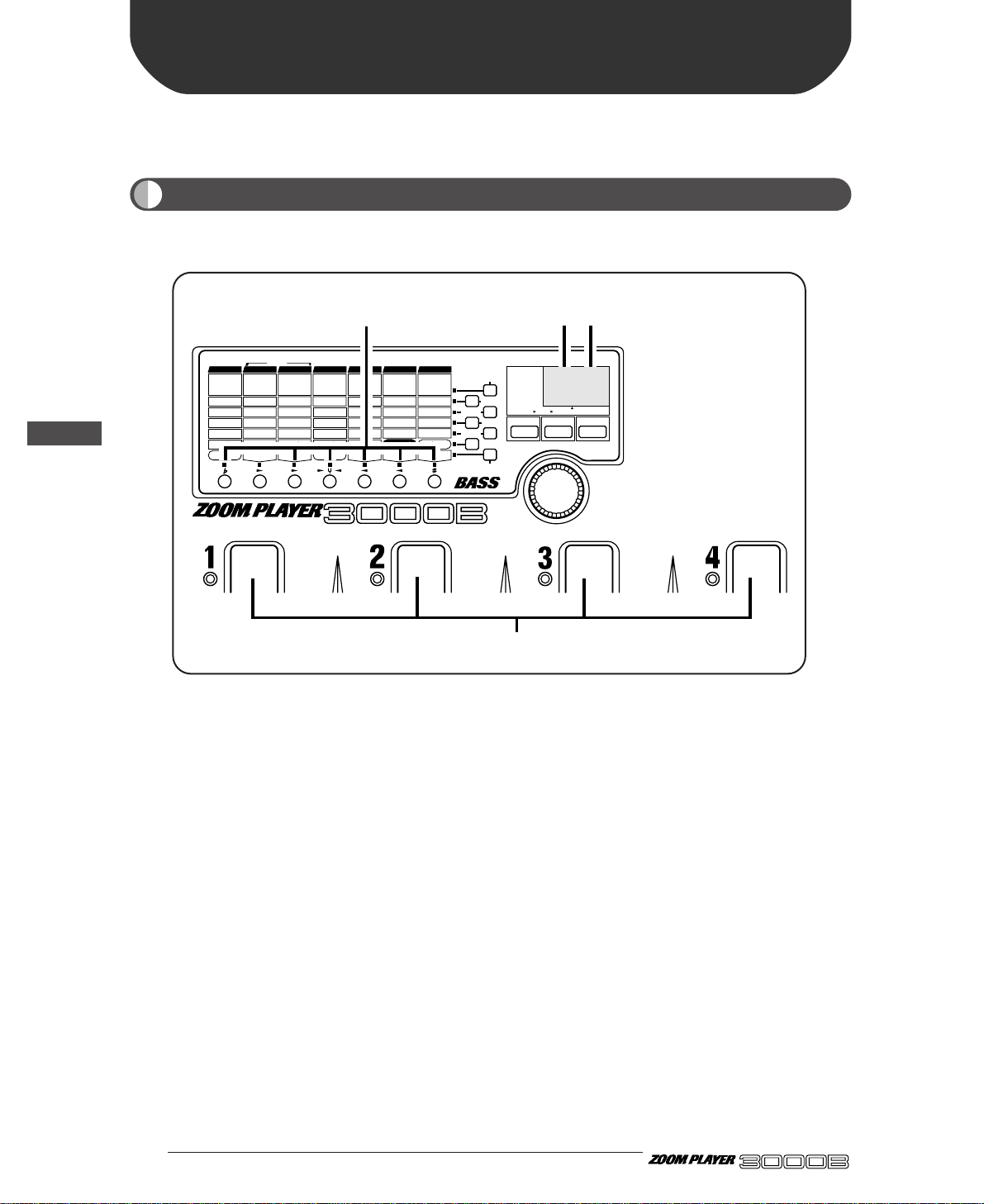
In Edit mode, the effect modules can be switched on or off freely.
17 ●
In Edit mode, the module LEDs light for effect modules that are
currently on. The LED for the module that is selected for editing flashes.
By pressing the MODULE Select key directly under the module LED,
this LED starts to flash.
The MODULE key can be used to toggle the module on or off. When
off, the module LED goes out.
• The module on/off state can be stored as part of a patch, by
performing the store operation as described on page 19.
• In Manual mode, the BANK switch and Foot Switches 1 - 4 can
be used to switch modules on and off. For details, please refer to
page 23.
• In Play mode, modules can be switched on and off by pressing
the Module Select keys.
BANK
FUNCTION
VALUE
ADVANCED BASS EFFECTS PROCESSOR
1.
COMP2.COMP2
3.LIMITER
4.
DUAL COMP
5.
DEFRET
6.
SLAP
Sens/Sens 1
A
tk
/
Sens 2
P
eak
/
X-F
T
one
/
Bal
Level
VOLUME RTM
G
ain
/
Mid Enh
Level
D.Level
Cabinet
1:DIST-WAH
2:WAH-DIST
DIST
/
AMP RTM
D
pt
/F1/
500Hz
Spd/G1/250Hz
Color/F2/100Hz
Mode/G2/500Hz
Level
WAH RTM
8
kHz
/
High/F1
4
kHz
/
MidF/G1
2
kHz
/
MidG/F2
1kH
z
/
Low/G2
L
evel
ZNR
F
req
/
Mode
Reso/Scale
Decay/Atk
D.Level
Level
SYNTH RTM
C
olor
/
Pit/Dly
Dpt/Sft/Mode
Rate/Tone
Mix/Bal/Reso
FUNCTION Mode
EFFECT RTM
D
lyTime
/
RevTime
FineTime/DlyMix
FB/RevColor
DlyMix/RevMix
Patch Level
DLY/REV RTM
1.CLN1
3.TE-C
5.OD
7.
FN-D
1.
GRAPHIC
2.3-BAND
3.PARAMETRIC
1-6.
BASS SYNTH
7.
HARMO SYNTH
1.DELAY
2.HALL
4.
EARLY REF
5.DLY+REV
3.ROOM
1.CHO
3.PIT
5.
DETUNE
7.
SWEEP
2.FLG
4.P-PIT
6.TRILL
8.RING
2.CLN2
4.SW-C
6.FUZZ
8.AC-D
1.AUTO
3.OCT
5.ENH
7.
GRAPHIC EQ
2.PEDAL
4.
PHASE
6.P-EQ
COMP DIST/AMP WAH EQ SYNTH EFFECT DLY/REV
POSITION
FUNCTION MODE
BANK(VALUE
)
EDIT(CANCEL)GROUP STORE
1.BANK DOWN
2.MANUAL
3.HOLD DLY(LONG)
4.HOLD DLY(REAL)
5.DELAY(TAP)
6.BYPASS
7.MUTE
9.RTM
PRESETUSER
(BOTH)
U
P
U O
MASTER LOW
MASTER MID
INPUT ATT
METRO TEMPO
METRO ON/OFF
METRO VOL
MASTER HIGH
1, 2
Switching Effect Modules On/Off
Use the Module Select keys to select the desired effect module.
Pressing the MODULE Select key once more turns the effect module on or off.
ADVANCED BASS EFFECTS PROCESSOR
HINTHINT
Changing the Patch Sound (Edit Mode Operation)
STEP
1
STEP
2
Page 22

When the Edit mode is first activated, the PATCH LEVEL parameter is
selected for editing. When the parameter is switched, the current value
of the parameter is shown on the display.
The topmost parameter controls the effect type for the entire effect
module.
The setting of the currently selected parameter changes.
The parameter changes made in this way are temporary. If you do
not store the new settings, they will return to the original values
when you return to Play mode and select another patch. (Global
parameters revert to the original setting when the unit is turned off.)
For information on storing patches, please refer to page 19.
After returning to the Play mode, the most recently edited
parameter is still stored in memory. If you return to Edit mode
before switching to another patch, you can edit the same parameter
again.
HINTHINT
NOTE
HINTHINT
● 18
ADVANCED BASS EFFECTS PROCESSOR
You can choose any parameter of an effect module and change the setting and value as desired.
BANK
FUNCTION
VALUE
ADVANCED BASS EFFECTS PROCESSOR
1.
COMP2.COMP2
3.LIMITER
4.
DUAL COMP
5.
DEFRET
6.
SLAP
Sens/Sens 1
A
tk
/
Sens 2
P
eak
/
X-F
T
one
/
Bal
Level
VOLUME RTM
G
ain
/
Mid Enh
Level
D.Level
Cabinet
1:DIST-WAH
2:WAH-DIST
DIST
/
AMP RTM
D
pt
/F1/
500Hz
Spd/G1/250Hz
Color/F2/100Hz
Mode/G2/500Hz
Level
WAH RTM
8
kHz
/
High/F1
4
kHz
/
MidF/G1
2
kHz
/
MidG/F2
1kH
z
/
Low/G2
L
evel
ZNR
F
req
/
Mode
Reso/Scale
Decay/Atk
D.Level
Level
SYNTH RTM
C
olor
/
Pit/Dly
Dpt/Sft/Mode
Rate/Tone
Mix/Bal/Reso
FUNCTION Mode
EFFECT RTM
D
lyTime
/
RevTime
FineTime/DlyMix
FB/RevColor
DlyMix/RevMix
Patch Level
DLY/REV RTM
1.CLN1
3.TE-C
5.OD
7.
FN-D
1.
GRAPHIC
2.3-BAND
3.PARAMETRIC
1-6.
BASS SYNTH
7.
HARMO SYNTH
1.DELAY
2.HALL
4.
EARLY REF
5.DLY+REV
3.ROOM
1.CHO
3.PIT
5.
DETUNE
7.
SWEEP
2.FLG
4.P-PIT
6.TRILL
8.RING
2.CLN2
4.SW-C
6.FUZZ
8.AC-D
1.AUTO
3.OCT
5.ENH
7.
GRAPHIC EQ
2.PEDAL
4.
PHASE
6.P-EQ
COMP DIST/AMP WAH EQ SYNTH EFFECT DLY/REV
POSITION
FUNCTION MODE
BANK(VALUE
)
EDIT(CANCEL)GROUP STORE
1.BANK DOWN
2.MANUAL
3.HOLD DLY(LONG)
4.HOLD DLY(REAL)
5.DELAY(TAP)
6.BYPASS
7.MUTE
9.RTM
PRESETUSER
(BOTH)
U
P
U O
MASTER LOW
MASTER MID
INPUT ATT
METRO TEMPO
METRO ON/OFF
METRO VOL
MASTER HIGH
1
2
1
Module LED flashing
MASTER LOW
MASTER MID
INPUT ATT
METRO TEMPO
METRO ON/OFF
METRO VOL
MASTER HIGH
Parameter LED flashing
VALUE
Changing Parameter Settings of Effects
Use the Module Select keys and Parameter Select keys to move the flashing
module LED and parameter LED to the parameter you want to edit.
Operate the VALUE knob.
Change other parameters in the same way.
Changing the Patch Sound (Edit Mode Operation)
STEP
STEP
STEP
1
2
3
Page 23

As long as you do not store in memory any patches edited in Edit mode, the original status will be
returned when you select another patch. The following paragraphs describe how to store patches.
19 ●
This will invoke the store standby status, and the module LEDs, and
parameter LEDs, will flash. In this status, you can specify the bank
number and patch number of the storage destination.
Even though you can change the parameters of the patches of the
PRESET group, you cannot write over them. Instead, when you
have changed a patch of the PRESET group, the storage destination
can only be "U" (USER group).
You can store in either Play mode or Edit mode.
If you do not make any particular specification, the destination will be
the original patch of the USER group. When store has not been
specified by the PRESET group, the patch is stored in Patch 1, Bank 0
of the USER group.
When you store parameters, the patch data already in the storage
destination will be erased. Check to make sure you do not need the
patch in the storage destination.
If the STORE key was not pressed for the second time, pressing the
EDIT key will abandon the store procedure and return to the
previous condition (before step 1).
NOTE
NOTE
HINTHINT
NOTE
BANK
FUNCTION
VALUE
ADVANCED BASS EFFECTS PROCESSOR
1.
COMP2.COMP2
3.LIMITER
4.
DUAL COMP
5.
DEFRET
6.
SLAP
Sens/Sens 1
A
tk
/
Sens 2
P
eak
/
X-F
T
one
/
Bal
Level
VOLUME RTM
G
ain
/
Mid Enh
Level
D.Level
Cabinet
1:DIST-WAH
2:WAH-DIST
DIST
/
AMP RTM
D
pt
/F1/
500Hz
Spd/G1/250Hz
Color/F2/100Hz
Mode/G2/500Hz
Level
WAH RTM
8
kHz
/
High/F1
4
kHz
/
MidF/G1
2
kHz
/
MidG/F2
1kH
z
/
Low/G2
L
evel
ZNR
F
req
/
Mode
Reso/Scale
Decay/Atk
D.Level
Level
SYNTH RTM
C
olor
/
Pit/Dly
Dpt/Sft/Mode
Rate/Tone
Mix/Bal/Reso
FUNCTION Mode
EFFECT RTM
D
lyTime
/
RevTime
FineTime/DlyMix
FB/RevColor
DlyMix/RevMix
Patch Level
DLY/REV RTM
1.CLN1
3.TE-C
5.OD
7.
FN-D
1.
GRAPHIC
2.3-BAND
3.PARAMETRIC
1-6.
BASS SYNTH
7.
HARMO SYNTH
1.DELAY
2.HALL
4.
EARLY REF
5.DLY+REV
3.ROOM
1.CHO
3.PIT
5.
DETUNE
7.
SWEEP
2.FLG
4.P-PIT
6.TRILL
8.RING
2.CLN2
4.SW-C
6.FUZZ
8.AC-D
1.AUTO
3.OCT
5.ENH
7.
GRAPHIC EQ
2.PEDAL
4.
PHASE
6.P-EQ
COMP DIST/AMP WAH EQ SYNTH EFFECT DLY/REV
POSITION
FUNCTION MODE
BANK(VALUE
)
EDIT(CANCEL)GROUP STORE
1.BANK DOWN
2.MANUAL
3.HOLD DLY(LONG)
4.HOLD DLY(REAL)
5.DELAY(TAP)
6.BYPASS
7.MUTE
9.RTM
PRESETUSER
(BOTH)
U
P
U O
MASTER LOW
MASTER MID
INPUT ATT
METRO TEMPO
METRO ON/OFF
METRO VOL
MASTER HIGH
1, 3
2
STORE
STORE
BANK
Storing Patches
Press the STORE key.
Using the BANK switch and Foot Switches 1 – 4, specify the patch storage
destination.
Press the STORE key again. This completes the storage operation, and returns
the 3000B to the Play mode.
ADVANCED BASS EFFECTS PROCESSOR
Changing the Patch Sound (Edit Mode Operation)
STEP
1
STEP
2
STEP
3
Page 24

The 3000B goes into the store standby mode, and the module LED and
parameter LED are flashing.
Only numbers from the USER group can be selected as copy target.
When a patch is copied, the patch in the target number will be
overwritten (erased). Make sure that you do not need the patch in
the target location before carrying out the copying operation.
The selected patch is stored in the copy target number.
If you press the EDIT key before pressing the STORE key the
second time, the copy operation will be canceled and the unit
returns to the condition of step 1.
NOTE
NOTE
● 20
ADVANCED BASS EFFECTS PROCESSOR
Patches of the 3000B can be copied to any desired number in the USER group. For example, if you want
to use several patches in a song, copying them to the same bank will make it easy to select them during a
performance.
BANK
FUNCTION
VALUE
ADVANCED BASS EFFECTS PROCESSOR
1.
COMP2.COMP2
3.LIMITER
4.
DUAL COMP
5.
DEFRET
6.
SLAP
Sens/Sens 1
A
tk
/
Sens 2
P
eak
/
X-F
T
one
/
Bal
Level
VOLUME RTM
G
ain
/
Mid Enh
Level
D.Level
Cabinet
1:DIST-WAH
2:WAH-DIST
DIST
/
AMP RTM
D
pt
/F1/
500Hz
Spd/G1/250Hz
Color/F2/100Hz
Mode/G2/500Hz
Level
WAH RTM
8
kHz
/
High/F1
4
kHz
/
MidF/G1
2
kHz
/
MidG/F2
1kH
z
/
Low/G2
L
evel
ZNR
F
req
/
Mode
Reso/Scale
Decay/Atk
D.Level
Level
SYNTH RTM
C
olor
/
Pit/Dly
Dpt/Sft/Mode
Rate/Tone
Mix/Bal/Reso
FUNCTION Mode
EFFECT RTM
D
lyTime
/
RevTime
FineTime/DlyMix
FB/RevColor
DlyMix/RevMix
Patch Level
DLY/REV RTM
1.CLN1
3.TE-C
5.OD
7.
FN-D
1.
GRAPHIC
2.3-BAND
3.PARAMETRIC
1-6.
BASS SYNTH
7.
HARMO SYNTH
1.DELAY
2.HALL
4.
EARLY REF
5.DLY+REV
3.ROOM
1.CHO
3.PIT
5.
DETUNE
7.
SWEEP
2.FLG
4.P-PIT
6.TRILL
8.RING
2.CLN2
4.SW-C
6.FUZZ
8.AC-D
1.AUTO
3.OCT
5.ENH
7.
GRAPHIC EQ
2.PEDAL
4.
PHASE
6.P-EQ
COMP DIST/AMP WAH EQ SYNTH EFFECT DLY/REV
POSITION
FUNCTION MODE
BANK(VALUE
)
EDIT(CANCEL)GROUP STORE
1.BANK DOWN
2.MANUAL
3.HOLD DLY(LONG)
4.HOLD DLY(REAL)
5.DELAY(TAP)
6.BYPASS
7.MUTE
9.RTM
PRESETUSER
(BOTH)
U
P
U O
MASTER LOW
MASTER MID
INPUT ATT
METRO TEMPO
METRO ON/OFF
METRO VOL
MASTER HIGH
2, 4
3
Copying a Patch to Another Location
In Play mode, select the patch you want to copy. (The patch can be from the
USER group or the PRESET group.)
Press the STORE key.
Use the BANK switch and the Foot Switches 1 - 4 to specify the copy target
number
Press the STORE key once more.
Changing the Patch Sound (Edit Mode Operation)
STEP
STEP
STEP
STEP
1
2
3
4
BANK
STORE
STORE
Page 25

The EFFECT module LED flashes.
FUNCTION Mode is a global parameter which serves for controlling the
FUNCTION switch. The setting is not affected by the on/off status of
the module.
The following FUNCTION switch modes 1 - 9 are available.
1: BANK DOWN
Switches the bank to the next lower number (opposite direction from
the BANK switch).
This mode is useful when banks are to be switched often during a
performance.
The FUNCTION switch action is selected in Edit mode.
The FUNCTION switch on the top panel of the 3000B is a special switch whose action can be selected
by the user. There are nine preprogrammed modes for the FUNCTION switch which provide functions
for various applications. This section describes how to select the FUNCTION switch mode and how to
use the switch.
21 ●
BANK
FUNCTION
VALUE
ADVANCED BASS EFFECTS PROCESSOR
1.
COMP2.COMP2
3.LIMITER
4.
DUAL COMP
5.
DEFRET
6.
SLAP
Sens/Sens 1
A
tk
/
Sens 2
P
eak
/
X-F
T
one
/
Bal
Level
VOLUME RTM
G
ain
/
Mid Enh
Level
D.Level
Cabinet
1:DIST-WAH
2:WAH-DIST
DIST
/
AMP RTM
D
pt
/F1/
500Hz
Spd/G1/250Hz
Color/F2/100Hz
Mode/G2/500Hz
Level
WAH RTM
8
kHz
/
High/F1
4
kHz
/
MidF/G1
2
kHz
/
MidG/F2
1kH
z
/
Low/G2
L
evel
ZNR
F
req
/
Mode
Reso/Scale
Decay/Atk
D.Level
Level
SYNTH RTM
C
olor
/
Pit/Dly
Dpt/Sft/Mode
Rate/Tone
Mix/Bal/Reso
FUNCTION Mode
EFFECT RTM
D
lyTime
/
RevTime
FineTime/DlyMix
FB/RevColor
DlyMix/RevMix
Patch Level
DLY/REV RTM
1.CLN1
3.TE-C
5.OD
7.
FN-D
1.
GRAPHIC
2.3-BAND
3.PARAMETRIC
1-6.
BASS SYNTH
7.
HARMO SYNTH
1.DELAY
2.HALL
4.
EARLY REF
5.DLY+REV
3.ROOM
1.CHO
3.PIT
5.
DETUNE
7.
SWEEP
2.FLG
4.P-PIT
6.TRILL
8.RING
2.CLN2
4.SW-C
6.FUZZ
8.AC-D
1.AUTO
3.OCT
5.ENH
7.
GRAPHIC EQ
2.PEDAL
4.
PHASE
6.P-EQ
COMP DIST/AMP WAH EQ SYNTH EFFECT DLY/REV
POSITION
FUNCTION MODE
BANK(VALUE
)
EDIT(CANCEL)GROUP STORE
1.BANK DOWN
2.MANUAL
3.HOLD DLY(LONG)
4.HOLD DLY(REAL)
5.DELAY(TAP)
6.BYPASS
7.MUTE
9.RTM
PRESETUSER
(BOTH)
U
P
U O
MASTER LOW
MASTER MID
INPUT ATT
METRO TEMPO
METRO ON/OFF
METRO VOL
MASTER HIGH
3
4
1, 5
2
Selecting the Action of the FUNCTION Switch
Press the EDIT key to activate the Edit mode.
Use the Module Select keys to select the EFFECT module.
Use the Parameter Select keys to select parameter 5 (FUNCTION Mode).
Use the VALUE knob to select one of modes 1 - 9 listed below.
ADVANCED BASS EFFECTS PROCESSOR
Using the FUNCTION switch
Using the FUNCTION switch
FUNCTION Mode
EFFECT RTM
EDIT(CANCEL
)
FUNCTION Mode
EFFECT RTM
Patch Level
DLY/REV RTM
MASTER MID
VALUE
STEP
STEP
1
2
STEP
3
STEP
4
Page 26

● 22
ADVANCED BASS EFFECTS PROCESSOR
2: MANUAL
Toggles between Manual mode (in which Foot Switches 1 - 4 can be
used to individually switch modules on and off) and regular Play
mode. For information on Manual mode, please refer to page 23.
This mode is useful when modules are to be switched on and off
during a performance.
3: HOLD DLY (LONG)
4: HOLD DLY (REAL)
Controls the hold delay feature (page 24) for recording and playing a
phrase during a performance. In the HOLD DLY (LONG) mode,
maximum recording time is 6 seconds. In the HOLD DLY (REAL)
mode, maximum recording time is 3 seconds, with higher sound
quality.
5: DELAY (TAP)
Allows tap input of the delay time for the hold delay feature (page
26). Useful for controlling the delay time according to the tempo of a
song.
6: SYNTH HOLD
In this mode, the sound produced by the SYNTH module is held
constant for as long as the FUNCTION switch is pressed. Pressing
the FUNCTION switch once more releases the hold mode.
7: BYPASS
8: MUTE
Toggles the Bypass state or Mute state on and off. When one of
these FUNCTION switch modes is selected, the Foot Switches 1 - 4
cannot be used to control the Bypass state (page 9) or Mute state
(page 10). This is to prevent inadvertent activation of Bypass or
Mute during a performance.
9: RTM
Controls a selected effect parameter or the volume in real time. For
details, please refer to page 27.
The 3000B returns to the Play mode.
FUNCTION Mode is a global parameter whose setting does not
change when a different patch is selected. If not stored, the setting
reverts to the previous value when the unit is turned off and then on
again. When wishing to store the setting, select any patch in the
USER group and store it as described on page 19.
NOTE
EDIT(CANCEL
)
Press the EDIT key once more.
Using the FUNCTION switch
STEP
5
Page 27

23 ●
ADVANCED BASS EFFECTS PROCESSOR
In Manual mode, effect modules can be switched on and off individually during a performance. When the
FUNCTION Mode parameter is set to "2", the FUNCTION switch can be used to toggle between Manual
mode and regular Play mode. Manual mode operation is described below.
The indication "Mn" appears on the display.
The FUNCTION LED lights up.
In Manual mode, the BANK Switch is used to assign effect modules to
Foot Switches 1 - 4.
When the LED of the BANK switch is lit, the
following effect modules can be assigned to
the Foot Switches 1 - 4.
When the BANK switch was pressed and the
LED flashes, the following modules can be
assigned to the Foot Switches 1 - 4.
The FUNCTION LED goes out and the 3000B returns to Play mode.
BANK
FUNCTION
VALUE
ADVANCED BASS EFFECTS PROCESSOR
1.
COMP2.COMP2
3.LIMITER
4.
DUAL COMP
5.
DEFRET
6.
SLAP
Sens/Sens 1
A
tk
/
Sens 2
P
eak
/
X-F
T
one
/
Bal
Level
VOLUME RTM
G
ain
/
Mid Enh
Level
D.Level
Cabinet
1:DIST-WAH
2:WAH-DIST
DIST
/
AMP RTM
D
pt
/F1/
500Hz
Spd/G1/250Hz
Color/F2/100Hz
Mode/G2/500Hz
Level
WAH RTM
8
kHz
/
High/F1
4
kHz
/
MidF/G1
2
kHz
/
MidG/F2
1kH
z
/
Low/G2
L
evel
ZNR
F
req
/
Mode
Reso/Scale
Decay/Atk
D.Level
Level
SYNTH RTM
C
olor
/
Pit/Dly
Dpt/Sft/Mode
Rate/Tone
Mix/Bal/Reso
FUNCTION Mode
EFFECT RTM
D
lyTime
/
RevTime
FineTime/DlyMix
FB/RevColor
DlyMix/RevMix
Patch Level
DLY/REV RTM
1.CLN1
3.TE-C
5.OD
7.
FN-D
1.
GRAPHIC
2.3-BAND
3.PARAMETRIC
1-6.
BASS SYNTH
7.
HARMO SYNTH
1.DELAY
2.HALL
4.
EARLY REF
5.DLY+REV
3.ROOM
1.CHO
3.PIT
5.
DETUNE
7.
SWEEP
2.FLG
4.P-PIT
6.TRILL
8.RING
2.CLN2
4.SW-C
6.FUZZ
8.AC-D
1.AUTO
3.OCT
5.ENH
7.
GRAPHIC EQ
2.PEDAL
4.
PHASE
6.P-EQ
COMP DIST/AMP WAH EQ SYNTH EFFECT DLY/REV
POSITION
FUNCTION MODE
BANK(VALUE
)
EDIT(CANCEL)GROUP STORE
1.BANK DOWN
2.MANUAL
3.HOLD DLY(LONG)
4.HOLD DLY(REAL)
5.DELAY(TAP)
6.BYPASS
7.MUTE
9.RTM
PRESETUSER
(BOTH)
U
P
U O
MASTER LOW
MASTER MID
INPUT ATT
METRO TEMPO
METRO ON/OFF
METRO VOL
MASTER HIGH
3
2, 5
4
M n
FUNCTION
FUNCTION
Manual Mode
Set the FUNCTION switch to "2: MANUAL", as described on page 21.
Press the FUNCTION switch while the 3000B is in Play mode.
Use the BANK switch to select effect modules to be assigned to Foot Switches
1 - 4.
To switch to another patch, press the FUNCTION switch once more.
BANK
BANK
BANK
LED
BANK
LED
Foot switch Corresponding effect module
1
COMP module on/off
2 DIST/AMP module on/off
3 WAH module on/off
EQ module on/off
4
Foot switch Corresponding effect module
1
SYNTH module on/off
2 EFFECT module on/off
3 DLY/REV module on/off
4
Use the Foot Switches 1 - 4 to turn the respective effect module on or off.
Using the FUNCTION switch
STEP
STEP
1
2
STEP
3
STEP
4
STEP
5
Page 28

For information on how to select the mode, refer to page 21. In the
HOLD DLY (LONG) mode, maximum recording time is 6 seconds. In the
HOLD DLY (REAL) mode, maximum recording time is 3 seconds, with
higher sound quality. Choose the appropriate mode, depending on the
length of the phrase you want to record.
The FUNCTION switch LED lights up and recording starts.
The hold delay function operates independently from other effect
modules. It can be used at any time when the 3000B is in Play
mode.
The phrase is sampled for the length of the time that the FUNCTION
switch is pressed. When you release the switch, the phrase is repeated.
HINTHINT
● 24
ADVANCED BASS EFFECTS PROCESSOR
When the FUNCTION Mode parameter is set to "3: HOLD DLY (LONG)" or "4: HOLD DLY (REAL)",
the FUNCTION switch can be used to control the hold delay function. While you keep the FUNCTION
switch depressed, play is sampled (recorded digitally) and then repeated by the 3000B.
BANK
FUNCTION
VALUE
ADVANCED BASS EFFECTS PROCESSOR
1.
COMP2.COMP2
3.LIMITER
4.
DUAL COMP
5.
DEFRET
6.
SLAP
Sens/Sens 1
A
tk
/
Sens 2
P
eak
/
X-F
T
one
/
Bal
Level
VOLUME RTM
G
ain
/
Mid Enh
Level
D.Level
Cabinet
1:DIST-WAH
2:WAH-DIST
DIST
/
AMP RTM
D
pt
/F1/
500Hz
Spd/G1/250Hz
Color/F2/100Hz
Mode/G2/500Hz
Level
WAH RTM
8
kHz
/
High/F1
4
kHz
/
MidF/G1
2
kHz
/
MidG/F2
1kH
z
/
Low/G2
L
evel
ZNR
F
req
/
Mode
Reso/Scale
Decay/Atk
D.Level
Level
SYNTH RTM
C
olor
/
Pit/Dly
Dpt/Sft/Mode
Rate/Tone
Mix/Bal/Reso
FUNCTION Mode
EFFECT RTM
D
lyTime
/
RevTime
FineTime/DlyMix
FB/RevColor
DlyMix/RevMix
Patch Level
DLY/REV RTM
1.CLN1
3.TE-C
5.OD
7.
FN-D
1.
GRAPHIC
2.3-BAND
3.PARAMETRIC
1-6.
BASS SYNTH
7.
HARMO SYNTH
1.DELAY
2.HALL
4.
EARLY REF
5.DLY+REV
3.ROOM
1.CHO
3.PIT
5.
DETUNE
7.
SWEEP
2.FLG
4.P-PIT
6.TRILL
8.RING
2.CLN2
4.SW-C
6.FUZZ
8.AC-D
1.AUTO
3.OCT
5.ENH
7.
GRAPHIC EQ
2.PEDAL
4.
PHASE
6.P-EQ
COMP DIST/AMP WAH EQ SYNTH EFFECT DLY/REV
POSITION
FUNCTION MODE
BANK(VALUE
)
EDIT(CANCEL)GROUP STORE
1.BANK DOWN
2.MANUAL
3.HOLD DLY(LONG)
4.HOLD DLY(REAL)
5.DELAY(TAP)
6.BYPASS
7.MUTE
9.RTM
PRESETUSER
(BOTH)
U
P
U O
MASTER LOW
MASTER MID
INPUT ATT
METRO TEMPO
METRO ON/OFF
METRO VOL
MASTER HIGH
2, 3, 4
Recording/Playing a Phrase (Hold Delay)
Set the FUNCTION Mode parameter to "3: HOLD DLY (LONG)" or "4: HOLD DLY
(REAL)".
While playing your instrument, press the FUNCTION switch at the point where
you want to start sampling, and hold the FUNCTION switch down.
Release the FUNCTION switch at the point where you want to end sampling.
Record
Play Stop
[ Hold delay steps ]
Out
Lit Lit
FUNCTION switch
LED out
Using the FUNCTION switch
STEP
1
STEP
2
STEP
3
FUNCTION
FUNCTION
Page 29

If the FUNCTION switch is pressed for a longer interval than the
hold time, sampling ends before the switch is released, and repeat
play starts.
The FUNCTION switch LED goes out and playback stops. The most
recently recorded phrase remains stored in memory until the unit is
turned off.
• To start playback once more: Press the FUNCTION switch and
release it immediately. The most recently recorded phrase is played.
• To start recording once more: Press the FUNCTION switch and
keep it depressed, as described in step 2. The most recently
recorded phrase is erased, and recording starts again.
• If Bypass/Mute is activated during playback, playback stops
automatically. The most recently recorded phrase remains
stored in memory.
• If Bypass/Mute is activated during recording, the Store mode is
activated and recording stops automatically. The phrase
recorded up to that point remains stored in memory.
NOTE
NOTE
25 ●
When wishing to stop the sampling playback, press the FUNCTION switch once
more and release it immediately.
ADVANCED BASS EFFECTS PROCESSOR
FUNCTION
Press and release
Using the FUNCTION switch
STEP
4
Page 30

When the FUNCTION Mode parameter is set to "5: DELAY (TAP)", the FUNCTION switch can be
used to set the delay time for the effect types DELAY and DLY+REV (DLY/REV module). By using
this function as described below, you can easily set the delay time to match the music's tempo.
To use delay time tap input, select a patch which uses the effect type DELAY or DLY+REV from
the DLY/REV module. The effect type setting can be checked in the Edit mode (page 18).
In this mode, the FUNCTION switch LED will flash in sync with the
delay time.
The 3000B detects the interval in which the FUNCTION switch was
pressed, and the delay time will be set in the DLY/REV module.
If the FUNCTION switch operation interval exceeds the maximum delay
time, the original delay time setting remains active. The maximum delay
time is 1000 ms when the effect type is DELAY and 500 ms when the
effect type is DLY+REV.
• Delay time tap input can be performed in Play mode or Edit
mode. In either mode, the delay time setting will be lost when the
unit is turned off, unless the patch was stored. For information
on how to store patches, please refer to page 19.
• If the optional remote pedal RP01 is connected and set to
DELAY mode, delay time tap input is possible only with the foot
switch of the remote pedal RP01 (page 38).
BANK
FUNCTION
VALUE
ADVANCED BASS EFFECTS PROCESSOR
1.
COMP2.COMP2
3.LIMITER
4.
DUAL COMP
5.
DEFRET
6.
SLAP
Sens/Sens 1
A
tk
/
Sens 2
P
eak
/
X-F
T
one
/
Bal
Level
VOLUME RTM
G
ain
/
Mid Enh
Level
D.Level
Cabinet
1:DIST-WAH
2:WAH-DIST
DIST
/
AMP RTM
D
pt
/F1/
500Hz
Spd/G1/250Hz
Color/F2/100Hz
Mode/G2/500Hz
Level
WAH RTM
8
kHz
/
High/F1
4
kHz
/
MidF/G1
2
kHz
/
MidG/F2
1kH
z
/
Low/G2
L
evel
ZNR
F
req
/
Mode
Reso/Scale
Decay/Atk
D.Level
Level
SYNTH RTM
C
olor
/
Pit/Dly
Dpt/Sft/Mode
Rate/Tone
Mix/Bal/Reso
FUNCTION Mode
EFFECT RTM
D
lyTime
/
RevTime
FineTime/DlyMix
FB/RevColor
DlyMix/RevMix
Patch Level
DLY/REV RTM
1.CLN1
3.TE-C
5.OD
7.
FN-D
1.
GRAPHIC
2.3-BAND
3.PARAMETRIC
1-6.
BASS SYNTH
7.
HARMO SYNTH
1.DELAY
2.HALL
4.
EARLY REF
5.DLY+REV
3.ROOM
1.CHO
3.PIT
5.
DETUNE
7.
SWEEP
2.FLG
4.P-PIT
6.TRILL
8.RING
2.CLN2
4.SW-C
6.FUZZ
8.AC-D
1.AUTO
3.OCT
5.ENH
7.
GRAPHIC EQ
2.PEDAL
4.
PHASE
6.P-EQ
COMP DIST/AMP WAH EQ SYNTH EFFECT DLY/REV
POSITION
FUNCTION MODE
BANK(VALUE
)
EDIT(CANCEL)GROUP STORE
1.BANK DOWN
2.MANUAL
3.HOLD DLY(LONG)
4.HOLD DLY(REAL)
5.DELAY(TAP)
6.BYPASS
7.MUTE
9.RTM
PRESETUSER
(BOTH)
U
P
U O
MASTER LOW
MASTER MID
INPUT ATT
METRO TEMPO
METRO ON/OFF
METRO VOL
MASTER HIGH
2
FUNCTION
Step on
Function switch
twice
FUNCTION LED flash lit flash
[ Tap input steps ]
delay time
TIME
Delay Time Tap Input
Set the FUNCTION Mode parameter to "5: DELAY (TAP)", as described on page 21.
Step on the FUNCTION switch twice, to match the tempo.
● 26
ADVANCED BASS EFFECTS PROCESSOR
Using the FUNCTION switch
NOTE
STEP
1
STEP
2
NOTE
Page 31

When the FUNCTION Mode is set to "9: RTM", the so-called RTM (real-time modulation) function can
be used. RTM allows the user to change effect parameters in real time, using the FUNCTION switch.
To use RTM, the reference setting (before change by RTM) and the maximum or minimum value (after
change by RTM) must be set for each effect module.
27 ●
If the module is off, press the Module Select key once more to turn it
on.
Effect parameters of the COMP module and EQ module cannot be
controlled by RTM.
Which parameter can be controlled depends on the effect type. In the
"Effect Types and Parameters" table on page 40–52, the parameter
NOTE
BANK
FUNCTION
VALUE
ADVANCED BASS EFFECTS PROCESSOR
1.
COMP2.COMP2
3.LIMITER
4.
DUAL COMP
5.
DEFRET
6.
SLAP
Sens/Sens 1
A
tk
/
Sens 2
P
eak
/
X-F
T
one
/
Bal
Level
VOLUME RTM
G
ain
/
Mid Enh
Level
D.Level
Cabinet
1:DIST-WAH
2:WAH-DIST
DIST
/
AMP RTM
D
pt
/F1/
500Hz
Spd/G1/250Hz
Color/F2/100Hz
Mode/G2/500Hz
Level
WAH RTM
8
kHz
/
High/F1
4
kHz
/
MidF/G1
2
kHz
/
MidG/F2
1kH
z
/
Low/G2
L
evel
ZNR
F
req
/
Mode
Reso/Scale
Decay/Atk
D.Level
Level
SYNTH RTM
C
olor
/
Pit/Dly
Dpt/Sft/Mode
Rate/Tone
Mix/Bal/Reso
FUNCTION Mode
EFFECT RTM
D
lyTime
/
RevTime
FineTime/DlyMix
FB/RevColor
DlyMix/RevMix
Patch Level
DLY/REV RTM
1.CLN1
3.TE-C
5.OD
7.
FN-D
1.
GRAPHIC
2.3-BAND
3.PARAMETRIC
1-6.
BASS SYNTH
7.
HARMO SYNTH
1.DELAY
2.HALL
4.
EARLY REF
5.DLY+REV
3.ROOM
1.CHO
3.PIT
5.
DETUNE
7.
SWEEP
2.FLG
4.P-PIT
6.TRILL
8.RING
2.CLN2
4.SW-C
6.FUZZ
8.AC-D
1.AUTO
3.OCT
5.ENH
7.
GRAPHIC EQ
2.PEDAL
4.
PHASE
6.P-EQ
COMP DIST/AMP WAH EQ SYNTH EFFECT DLY/REV
POSITION
FUNCTION MODE
BANK(VALUE
)
EDIT(CANCEL)GROUP STORE
1.BANK DOWN
2.MANUAL
3.HOLD DLY(LONG)
4.HOLD DLY(REAL)
5.DELAY(TAP)
6.BYPASS
7.MUTE
9.RTM
PRESETUSER
(BOTH)
U
P
U O
MASTER LOW
MASTER MID
INPUT ATT
METRO TEMPO
METRO ON/OFF
METRO VOL
MASTER HIGH
1, 9
3, 5, 7
11, 12
2
3, 4, 6
EDIT(CANCEL
)
METRO TEMPO
METRO ON/OFF
METRO VOL
VALUE
Adjusting Effect Parameters in Real Time (RTM)
Press the EDIT key to activate the Edit mode.
Use the Module Select keys to choose the module to be controlled by RTM.
Use the Parameter Select keys and the VALUE knob to choose the effect type.
ADVANCED BASS EFFECTS PROCESSOR
Using the FUNCTION switch
Use the Parameter Select keys to choose the effect parameter to be controlled by
RTM.
STEP
STEP
1
2
STEP
STEP
3
4
Page 32

marked with " ← RTM" can be controlled by RTM. For example, when
the effect type CHO is selected for the EFFECT module, the "Mix"
parameter can be controlled by RTM.
The value set in this way becomes the reference setting for RTM.
For every effect module except for the COMP module and EQ module,
parameter 6 is the RTM parameter which determines the maximum (or
minimum) value that is reached by RTM control.
For example, if the "Mix" parameter was set to "50" in step 5, and the
RTM parameter is "0", the adjustment range is 0 - 50. When the
parameter is "100", the adjustment range is 50 - 100. When the RTM
parameter is "oF", RTM control cannot be used for that module.
Depending on the effect type, the RTM parameter causes a change
in the upward or downward direction. In some cases, only RTM on
or off can be set. For details, please refer to "Effect Types and
Parameters" (pages 40–52).
If necessary, store the patch as described on page 19. The RTM setting
can be stored individually for each patch.
For details, please refer to page 21.
The value of the effect parameter selected in step 5 changes gradually
towards the maximum (minimum) value set in step 7, causing a change
in the sound quality of the patch. When the maximum (minimum) value
is reached, the parameter remains constant also if the FUNCTION
switch is still depressed.
NOTE
● 28
ADVANCED BASS EFFECTS PROCESSOR
MASTER LOW
MASTER MID
VALUE
VALUE
EDIT(CANCEL
)
Use the VALUE knob to adjust the value of the effect parameter.
Use the Parameter Select keys to choose parameter 6.
If desired, repeat steps 2 through 7 to make the RTM setting for other effect
modules.
Use the VALUE knob to adjust the RTM parameter.
When the setting is completed, press the EDIT key to revert to Play mode.
Set the FUNCTION Mode to "9: RTM".
FUNCTION
Using the FUNCTION switch
While playing your instrument, press and hold the FUNCTION switch.
STEP
STEP
STEP
5
6
7
STEP
STEP
STEP
STEP
8
9
10
11
Page 33

29 ●
The RTM control target parameter gradually returns to the original
value.
• You can release the FUNCTION switch already before the
maximum (minimum) value is reached. The setting will
gradually return to the original value. For some effect
parameters, simply pressing and releasing the FUNCTION
switch will yield an interesting effect. We recommend that you
try out the various possibilities.
• When the remote pedal RP01 is connected, RTM can also be
controlled with the foot pedal of the RP01.
STEP
Release the FUNCTION switch.
ADVANCED BASS EFFECTS PROCESSOR
FUNCTION
switch
FUNCTION
switch
Reference value
Reference value < RTM parameter
Reference value
minimum value
maximum value
Reference value > RTM parameter
Using the FUNCTION switch
12
HINTHINT
FUNCTION
Page 34

Parameter 6 of the COMP module serves for turning Volume RTM on
and off.
Volume RTM can now be used.
If necessary, store the patch as described on page 19. The Volume
RTM setting can be stored for each patch.
For details, please refer to page 21.
● 30
ADVANCED BASS EFFECTS PROCESSOR
When the FUNCTION mode is set to "9: RTM", the Volume RTM function is also available, allowing
volume adjustment in real time. This makes it possible to easily perform fade- out or fade-in during a
performance.
BANK
FUNCTION
VALUE
ADVANCED BASS EFFECTS PROCESSOR
1.
COMP2.COMP2
3.LIMITER
4.
DUAL COMP
5.
DEFRET
6.
SLAP
Sens/Sens 1
A
tk
/
Sens 2
P
eak
/
X-F
T
one
/
Bal
Level
VOLUME RTM
G
ain
/
Mid Enh
Level
D.Level
Cabinet
1:DIST-WAH
2:WAH-DIST
DIST
/
AMP RTM
D
pt
/F1/
500Hz
Spd/G1/250Hz
Color/F2/100Hz
Mode/G2/500Hz
Level
WAH RTM
8
kHz
/
High/F1
4
kHz
/
MidF/G1
2
kHz
/
MidG/F2
1kH
z
/
Low/G2
L
evel
ZNR
F
req
/
Mode
Reso/Scale
Decay/Atk
D.Level
Level
SYNTH RTM
C
olor
/
Pit/Dly
Dpt/Sft/Mode
Rate/Tone
Mix/Bal/Reso
FUNCTION Mode
EFFECT RTM
D
lyTime
/
RevTime
FineTime/DlyMix
FB/RevColor
DlyMix/RevMix
Patch Level
DLY/REV RTM
1.CLN1
3.TE-C
5.OD
7.
FN-D
1.
GRAPHIC
2.3-BAND
3.PARAMETRIC
1-6.
BASS SYNTH
7.
HARMO SYNTH
1.DELAY
2.HALL
4.
EARLY REF
5.DLY+REV
3.ROOM
1.CHO
3.PIT
5.
DETUNE
7.
SWEEP
2.FLG
4.P-PIT
6.TRILL
8.RING
2.CLN2
4.SW-C
6.FUZZ
8.AC-D
1.AUTO
3.OCT
5.ENH
7.
GRAPHIC EQ
2.PEDAL
4.
PHASE
6.P-EQ
COMP DIST/AMP WAH EQ SYNTH EFFECT DLY/REV
POSITION
FUNCTION MODE
BANK(VALUE
)
EDIT(CANCEL)GROUP STORE
1.BANK DOWN
2.MANUAL
3.HOLD DLY(LONG)
4.HOLD DLY(REAL)
5.DELAY(TAP)
6.BYPASS
7.MUTE
9.RTM
PRESETUSER
(BOTH)
U
P
U O
MASTER LOW
MASTER MID
INPUT ATT
METRO TEMPO
METRO ON/OFF
METRO VOL
MASTER HIGH
1, 4
3
6, 7
2
2
EDIT(CANCEL
)
MASTER LOW
MASTER MID
VOLUME RTM
Controlling the Volume in Real Time (Volume RTM)
Use the Module Select keys and the Parameter Select keys to choose parameter
6 (Volume RTM) of the COMP module.
Press the EDIT key to activate the Edit mode.
Use the VALUE knob to set the display indication to "on".
VALUE
o
n
Press the EDIT key to revert to Play mode.
Set the FUNCTION Mode to "9: VOLUME".
Using the FUNCTION switch
STEP
STEP
1
2
STEP
3
STEP
4
STEP
5
)
EDIT(CANCEL
Page 35

31 ●
The effect volume will be gradually reduced to zero.
The volume here refers to the input level of the EFFECT module,
not the overall level of the 3000B. If for example delay or reverb is
used, only the original sound is reduced, and the delay or reverb
sound is still audible.
The volume gradually returns to the original value.
• In step 6, you can release the FUNCTION switch before the
volume zero point is reached. The setting will gradually return
to the original value.
• When the remote pedal RP01 is connected, Volume RTM can
also be controlled with the foot pedal of the RP01.
NOTE
FUNCTION
FUNCTION
FUNCTION
switch
VOLUME
No sound
Reference value
Using the FUNCTION switch
STEP
While playing your instrument, press and hold the FUNCTION switch.
Release the FUNCTION switch.
HINTHINT
FUNCTION
switch LED lit
FUNCTION switch
LED OUT
■ Volume RTM on
6
STEP
7
ADVANCED BASS EFFECTS PROCESSOR
Page 36

The indication "AL" appears on the display and the module LED and
parameter LED are flashing. This indicates that the unit is ready for the
All Initialize function.
• To perform All Initialize:
→ Proceed to step 3.
• To perform factory Recall:
→ Use the BANK switch and Foot Switches 1 - 4 to select the patch
from the USER group which you want to return to the default
condition.
* When wishing to terminate the procedure, press the EDIT key. (The
unit reverts to Play mode.)
When All Initialize is being carried out, the module LED and parameter
LED are flashing quickly. When initialization is completed, the unit
automatically reverts to Play mode.
When Factory Recall is being carried out, the module LED and
parameter LED are flashing quickly and the specified patch is restored.
The unit then remains in standby mode for more patches. When
wishing to terminate Factory Recall, press the EDIT key to return to
Play mode.
STORE
STORE
A L
This section describes use of the Special mode (All Initialize and Factory Recall).
All Initialize is a special function for returning all the patches in the USER group and the values of the
global parameters to their factory settings. Factory Recall allows selective return of a specified patch to
the factory default.
Keep in mind that any patches you have stored will be erased if you implement the All Initialize function.
● 32
ADVANCED BASS EFFECTS PROCESSOR
Returning the 3000B to the Factory Default Settings
Cut the power supply to the 3000B. ( Be sure to turn the amplifier volume down to
minimum.)
Press the STORE key once more.
NOTE
Returning the 3000B to the Factory Default Settings
U
BANK(VALUE
U O
PRESETUSER
P
)
(BOTH)
VALUE
STEP
STEP
POSITION
COMP DIST/AMP WAH EQ SYNTH EFFECT DLY/REV
1.
COMP2.COMP2
1.CLN1
3.LIMITER
3.TE-C
4.
DUAL COMP
5.OD
5.
DEFRET
6.
SLAP
7.
ain
G
Sens/Sens 1
/
A
tk
Sens 2
/
P
eak
X-F
/
T
one
Bal
1:DIST-WAH
Level
2:WAH-DIST
DIST
VOLUME RTM
ADVANCED BASS EFFECTS PROCESSOR
1.
GRAPHIC
BASS SYNTH
2.CLN2
1.AUTO
2.PEDAL
4.SW-C
3.OCT
4.
2.3-BAND
PHASE
6.FUZZ
5.ENH
3.PARAMETRIC
6.P-EQ
8.AC-D
7.
FN-D
GRAPHIC EQ
/
/F1/
pt
D
Spd/G1/250Hz
Color/F2/100Hz
Mode/G2/500Hz
Level
WAH RTM
/
500Hz
kHz
High/F1
8
/
4
kHz
MidF/G1
/
kHz
MidG/F2
2
/
1kH
z
Low/G2
L
evel
ZNR
Mid Enh
Level
D.Level
Cabinet
/
AMP RTM
1-6.
7.
HARMO SYNTH
req
F
Reso/Scale
Decay/Atk
D.Level
Level
SYNTH RTM
2.FLG
1.CHO
4.P-PIT
3.PIT
6.TRILL
DETUNE
5.
8.RING
7.
SWEEP
/
/
Mode
olor
Pit/Dly
C
Dpt/Sft/Mode
Rate/Tone
Mix/Bal/Reso
FUNCTION Mode
EFFECT RTM
1.DELAY
2.HALL
4.
EARLY REF
5.DLY+REV
lyTime
D
FineTime/DlyMix
FB/RevColor
DlyMix/RevMix
Patch Level
DLY/REV RTM
3.ROOM
/
RevTime
METRO VOL
MASTER HIGH
METRO ON/OFF
METRO TEMPO
INPUT ATT
MASTER MID
MASTER LOW
FUNCTION MODE
1.BANK DOWN
2.MANUAL
3.HOLD DLY(LONG)
4.HOLD DLY(REAL)
5.DELAY(TAP)
6.BYPASS
7.MUTE
9.RTM
EDIT(CANCEL)GROUP STORE
1
2
BANK
FUNCTION
2, 3
STEP
3
Page 37

Using the Remote Pedal
While it is possible to perform RTM control and delay time tap input using only the controls on the
3000B itself, connecting the optional remote pedal RP01 will make these functions even easier to use,
thereby increasing your playing scope during a performance.
This section explains various way of using the remote pedal RP01.
33 ●
Before connecting the RP01, make sure that power to the 3000B is off. Otherwise
proper operation is not assured.
NOTE
ADVANCED BASS EFFECTS PROCESSOR
Using the Remote Pedal
Names of Parts / Connections
PEDAL SW
MODE
SELECT
MONITOR
STATUS
MODE DELECT
PEDAL-WAH ON/OFF(PEDAL SW)
DELAY MODE
(PEDAL SW TRIGGER)
RTM MODE
VOLUME ASSIGN
PEDAL-PITCH ON/OFF(PEDAL SW)
PEDAL SW
MODE
SELECT
MONITOR
STATUS
MODE SELECT
PEDAL-WAH ON/OFF(PEDAL SW)
DELAY MODE
(PEDAL SW TRIGGER)
RTM MODE
VOLUME ASSIGN
PEDAL-PITCH ON/OFF(PEDAL SW)
300mA
DC9V OUTPUT
(PHONES)
INPUT
REMOTE IN
SERIAL NO.
Foot switch
STATUS LED
Effect Monitor LEDs
VOLUME ASSIGN LED
MODE LEDs
Mode Selector
Control pedal
(with integrated switch)
REMOTE OUT
REMOTE IN
RP01 Names of Parts / Functions
The RP01 has the following two modes, which serve for different functions.
• RTM mode
The remote pedal RP01 serves for continuously varying the effect parameter or volume of a patch. This
allows use for pedal wah or the pedal pitch shifter. When switching patches, the RP01 is always in RTM
mode.
• DELAY mode
This mode allows use of the switch on the RP01 for delay time tap input and for control of the delay
effect.
Page 38

● 34
ADVANCED BASS EFFECTS PROCESSOR
Using the Remote Pedal
Control functions (RTM mode)
Control functions (DELAY mode)
Push-down switch integrated in control pedal
Switches pedal wah or pedal pitch shifter on and off.
Foot switch
Switches pedal wah or pedal pitch shifter on and off.
PEDAL SW
PEDAL SW
STATUS
MONITOR
PEDAL-WAH ON/OFF(PEDAL SW)
PEDAL-PITCH ON/OFF(PEDAL SW)
VOLUME ASSIGN
MODE DELECT
RTM MODE
DELAY MODE
(PEDAL SW TRIGGER)
SELECT
MODE
SELECT
MODE
Mode Selector
Switches RP01 to DELAY mode.
Control pedal
Adjusts RTM parameter or Volume RTM.
STATUS
MONITOR
PEDAL-WAH ON/OFF(PEDAL SW)
PEDAL-PITCH ON/OFF(PEDAL SW)
VOLUME ASSIGN
MODE SELECT
RTM MODE
DELAY MODE
(PEDAL SW TRIGGER)
Status LED
Lights up when pedal wah or
pedal pitch shifter is switched,
and goes out when condition
returns to previous state.
Effect Monitor LEDs
Indicate on/off condition of
pedal wah, pedal pitch shifter,
and Volume RTM.
Mode LED
RTM MODE LED is lit.
Push-down switch integrated in control pedal
Switches DLY/REV module on and off.
Foot switch
Serves for delay time tap input.
PEDAL SW
PEDAL SW
STATUS
MONITOR
PEDAL-WAH ON/OFF(PEDAL SW)
PEDAL-PITCH ON/OFF(PEDAL SW)
VOLUME ASSIGN
MODE DELECT
RTM MODE
DELAY MODE
MODE
Control pedal
Adjusts RTM parameter of DLY/REV module.
(PEDAL SW TRIGGER)
SELECT
SELECT
MODE
Mode Selector
Switches RP01 to RTM mode.
STATUS
MONITOR
PEDAL-WAH ON/OFF(PEDAL SW)
PEDAL-PITCH ON/OFF(PEDAL SW)
VOLUME ASSIGN
MODE SELECT
RTM MODE
DELAY MODE
(PEDAL SW TRIGGER)
Status LED
Out.
Effect Monitor LEDs
Out.
Mode LED
DELAY MODE LED is lit.
Page 39

For details, please refer to page 21.
If the FUNCTION Mode is set to "9: RTM", the control pedal of the
RP01 will only function as master volume pedal.
FUNCTION switch (3000B) and control pedal (RP01) operation (RP01 in RTM mode)
For information on making settings for the RTM function, please refer to
page 21. When a patch has been called up, the RP01 is always in RTM
mode and the RTM MODE LED is lit.
The parameter adjusted with the control pedal depends on the effect
type selected for the patch and on the RTM/Volume RTM setting. It is
also possible to control several parameters at a time.
NOTE
Using the Remote Pedal
35 ●
This section describes how to use the RP01 for controlling RTM or Volume RTM.
Using the RP01 for Controlling the RTM Parameter (RTM Mode)
Verify that the RP01 is properly connected to the 3000B.
Set the FUNCTION switch (FUNCTION Mode parameter) to one of modes 1 - 8.
Call up a patch for which RTM/Volume RTM has been set.
Operate the control pedal of the RP01 while playing your
ADVANCED BASS EFFECTS PROCESSOR
PEDAL SW
MODE
SELECT
MONITOR
STATUS
MODE DELECT
PEDAL-WAH ON/OFF(PEDAL SW)
DELAY MODE
(PEDAL SW TRIGGER)
RTM MODE
VOLUME ASSIGN
PEDAL-PITCH ON/OFF(PEDAL SW)
5, 6
5, 6
4
When FUNCTION Mode
= 1 - 8
When FUNCTION Mode = 9
Function selected with
FUNCTION Mode parameter
RTM/Volume RTM control
Master volume control
Control pedal (RP01)
operation
RTM/Volume RTM control
FUNCTION switch
(3000B) operation
FUNCTION Mode
parameter setting
STEP
STEP
1
2
STEP
3
STEP
4
Page 40

■ If Volume RTM is ON
If the Volume RTM setting is ON for the
currently selected patch, the control pedal of
the RP01 can be used to continuously vary
the volume of the patch. When the pedal is
fully up, volume is zero. Pushing the pedal
down will gradually increase the volume.
The Volume RTM ON/OFF condition can be
checked with the VOLUME ASSIGN LED of the
RP01.
[ VOLUME ASSIGN LED RP01 ]
■ When pedal wah or pedal pitch is selected
If the WAH module is ON for the currently selected patch and
PEDAL is selected as effect type, the control pedal of the RP01 can
be used as a wah pedal. Similarly, if the EFFECT module is ON for
the currently selected patch and P-PIT is selected as effect type, the
control pedal of the RP01 can be used as a pitch shift pedal.
The change direction when the pedal is pressed depends on the
RTM parameter setting.
The pedal wah/pedal pitch setting and the ON/OFF state can be
checked with the Effect Monitor LED.
[ Effect Monitor LED]
■ When other RTM parameter is selected
If a parameter other than pedal wah/pedal pitch shift is set for the
currently selected patch, the control pedal of the RP01 can be used
to continuously vary that effect parameter. When the control pedal is
fully raised, the parameter is at the reference value. Pushing down
the pedal will gradually alter the parameter towards the maximum
(minimum) value.
● 36
ADVANCED BASS EFFECTS PROCESSOR
Using the Remote Pedal
RP01
Volume RTM on
VOLUME
No sound
PEDAL-WAH ON/OFF(PEDAL SW)
PEDAL-PITCH ON/OFF(PEDAL SW)
VOLUME ASSIGN
MODE SELECT
RTM MODE
When Volume RTM is ON: LED lit
PEDAL-WAH ON/OFF(PEDAL SW)
PEDAL-PITCH ON/OFF(PEDAL SW)
VOLUME ASSIGN
MODE SELECT
When Volume RTM is OFF: LED out
RTM MODE
MONITOR
PEDAL-WAH ON/OFF(PEDAL SW)
PEDAL-PITCH ON/OFF(PEDAL SW)
• When PEDAL/P-PIT is selected and module is on:
• When PEDAL/P-PIT is selected and module is off:
• When PEDAL/P-PIT is not selected for the module:
LED lit
LED flashing
LED out
Page 41

If the PEDAL parameter of the WAH module or the P-PIT parameter of
the EFFECT module is selected for the current patch, the control pedal
push-down switch or the foot switch of the RP01 can be used to toggle
the ON/OFF state. The Status LED lights up accordingly.
The Status LED goes out.
• When the Effect Monitor LED for pedal wah/pedal pitch shifter
is out (effect type PEDAL/P-PITCH is not selected in respective
module), the control pedal push-down switch and the foot switch
have no effect.
• Any change in the pedal wah/pedal pitch shifter on/off setting
and the RTM parameter is only temporary. When another patch
is selected, the settings of the new patch will become active.
37 ●
STEP
To switch the on/off state of pedal wah/pedal pitch shift, use the control pedal
push-down switch or the foot switch of the RP01.
To return the pedal wah/pedal pitch shifter to the original state, press the control
pedal push-down switch or foot switch once more.
ADVANCED BASS EFFECTS PROCESSOR
Using the Remote Pedal
RP01 RP01
Reference value
Value of
effect parameter
set by RTM
Reference value
Value of
effect parameter
set by RTM
Reference value < RTM parameter Reference value > RTM parameter
5
STEP
6
Status LED: Out
PEDAL (WAH module): On
P-PITCH (EFFECT module): Off
Control pedal push-down switch or
foot switch pressed
Status LED: Lit
PEDAL (WAH module): Off
P-PITCH (EFFECT module): On
STATUS
MONITOR
PEDAL-WAH ON/OFF(PEDAL SW)
PEDAL-PITCH ON/OFF(PEDAL SW)
STATUS
MONITOR
PEDAL-WAH ON/OFF(PEDAL SW)
PEDAL-PITCH ON/OFF(PEDAL SW)
HINTHINT
Page 42

For details, please refer to page 21.
When a new patch is selected, the RP01 is always in RTM mode. The
Mode Selector of the RP01 must therefore be used to activate the
DELAY mode.
• When the FUNCTION Mode is set to "9: RTM", the control
pedal of the RP01 is inactive.
• When the FUNCTION Mode is set to "5: (DELAY)", the RP01
functions normally, but the FUNCTION switch on the 3000B is
inactive.
FUNCTION switch (3000B) operation (RP01 = DELAY mode)
This section describes how to use the RP01 for tap input of the delay time and for on/off switching of the
DLY/REV module.
● 38
ADVANCED BASS EFFECTS PROCESSOR
PEDAL SW
MODE
SELECT
MONITOR
STATUS
MODE DELECT
PEDAL-WAH ON/OFF(PEDAL SW)
DELAY MODE
(PEDAL SW TRIGGER)
RTM MODE
VOLUME ASSIGN
PEDAL-PITCH ON/OFF(PEDAL SW)
7
5
4, 8
6
Using the RP01 for delay effect control (DELAY Mode)
Verify that the RP01 is properly connected to the 3000B.
Set the FUNCTION switch (FUNCTION Mode parameter) to one of modes 1 - 8.
Select a patch which uses the effect type DELAY or DLY+REV from the DLY/REV
module.
Push the Mode Selector of the RP01 to select DELAY mode. The DELAY MODE
LED lights up.
Using the Remote Pedal
STEP
STEP
STEP
STEP
1
2
3
4
MODE SELECT
NOTE
DELAY MODE
DELAY Mode LED lit
(PEDAL SW TRIGGER)
FUNCTION MODE
parameter setting
FUNCTION MODE
= 1 - 4, 6 - 8
FUNCTION MODE = 5
FUNCTION MODE = 9
Function selected with
FUNCTION Mode
Inactive
RTM/Volume RTM operation
FUNCTION switch
(3000B) operation
Page 43

The 3000B detects the interval in which the pedal switch was pressed,
and the delay time will be set in the DLY/REV module.
If the pedal switch operation interval exceeds the maximum delay time,
the original delay time setting remains active. The maximum delay time
is 1000 ms when the effect type is DELAY and 500 ms when the effect
type is DLY+REV.
The RP01 cannot be used for controlling the hold delay function. To
use hold delay, set the FUNCTION Mode parameter of the 3000B
to "3: HOLD DLY (LONG)" or "4: HOLD DLY (REAL)" and
operate the FUNCTION switch.
When the RP01 is in DELAY mode, the control pedal serves for RTM
control of the DLY/REV module.
When the RP01 is in DELAY mode, the control pedal push- down
switch serves for on/off switching of the DLY/REV module.
Any change made with the RP01 to the delay time, DLY/REV
module on/off setting, and RTM parameter is only temporary. When
a new patch is selected, the settings of that patch will become
active.
NOTE
NOTE
39 ●
STEP
To perform delay time tap input, press the RP01 pedal switch twice.
To vary the effect parameter of the DLY/REV module, move the control pedal of
the RP01 up or down.
To switch the DLY/REV module on and off, press the control pedal fully down to
operate the push-down switch.
To return the RP01 to the RTM mode, push the Mode Selector or select another
patch.
ADVANCED BASS EFFECTS PROCESSOR
Using the Remote Pedal
5
Press the RP01
pedal switch twice
STEP
STEP
STEP
6
7
8
Page 44

COMP (Compressor) Module
● 40
ADVANCED BASS EFFECTS PROCESSOR
This section explains all of the Zoom Player 3000B's effect types and parameters. However, parameters
that are the same for several effect types are only explained fully the first time they appear.
• Parameters marked with "G" are global parameters, and parameters marked with "P"
are patch parameters. These parameters can be changed regardless of the on/off
condition of the respective effect module.
• Parameters marked with "
←RTM" are parameters which can be operated by RTM
when that effect module is selected.
• Shaded sections ( )indicate that there are no setting items for the parameter.
When such a parameter is selected, the display only shows "
-..-.
".
■ Effect types
The following six effect types are available in the
COMP module.
Type 1 COMP (Compressor)
Type 2 COMP2 (Compressor 2)
Type 3 LIMITER
Type 4 DUAL COMP (Dual Compressor)
Type 5 DEFRET
Type 6 SLAP
Depending on the selected effect type, the content of
parameters 1, 2, 3, 4 changes.
■ Type 1 COMP (Compressor)
The compressor maintains the volume within a given
dynamic range by reducing attack intensity.
●Parameter 1 Sens
Determines the compressor depth.
●Parameter 2 Atk
Determines the time interval between the bass guitar
sound and the onset of the compressor effect.
●Parameter 3 Peak (Wild)
Higher values result in a more peak-oriented,
unrestrained sound.
●Parameter 4 Tone
Higher values result in a brighter sound.
■ Type 2 COMP2 (Compressor 2)
Compared to COMP, this effect type causes a less
intense sound change.
●Parameter 3 Peak (Release)
Determines the speed of compression release.
The parameter content is the same as for Type 1
(COMP).
■ Type 3 LIMITER
This effect keeps the sound below a certain level.
●Parameter 1 Sens (Threshold)
Determines the threshold from which the limiter
TYPE
1. COMP 2. COMP2 3. LIMITER 4. DUAL COMP 5. DEFRET 6. SLAP
COMP
Parameter 1
Sens Sens(Threshold) Sens1 Sens
1–50 1–50 1–50 1–50
Parameter 2
Atk Sens2 Atk
1–50 1–50 1–50
Parameter 3
Peak(Wild) Peak(Ratio) X-F
1–8
Peak(Release)
1–8 1–8 1–8
Parameter 4
Tone Bal
1–8 0–100
Parameter 5
Level
1–30
Parameter 6
VOLUME RTM (P)
oF, on
Effect Types and Parameters
Effect Types and Parameters
This module contains effects that influence the dynamic range, such as a compressor and limiter. The Volume
RTM setting is also made in this module.
Page 45

effect becomes active.
●Parameter 2 Atk
●Parameter 3 Peak (Ratio)
Determines the compression ratio for signals
exceeding the threshold. Higher values result in
higher compression ratio.
●Parameter 4 Tone
■ Type 4 DUAL COMP (Dual Compressor)
This effect allows choosing a different compression
value for the low range and high range.
●Parameter 1 Sens1
Determines the compressor depth for the high range.
●Parameter 2 Sens2
Determines the compressor depth for the low range.
●Parameter 3 X-F
Determines the frequency for dividing the high range
and low range.
●Parameter 4 Bal
Determines the level balance of high range and low
range.
■ Type 5 DEFRET
This effect simulates the slow-attack sound of a
fretless bass. The effect should be used only when
playing single notes.
● Parameter 1 Sens
Determines the input sensitivity.
●Parameter 2 Atk
Determines the attack speed.
■ Type 6 SLAP
This effect simulates the slap playing style with
sharp attacks. The effect should be used only when
playing single notes.
●Parameter 1 Sens
●Parameter 2 Atk
Higher values result in emphasized attack.
■ Common parameters for Type 1 - 6
●Parameter 5 Level
Determines the module output level.
●Parameter 6 Volume RTM (P)
This is a patch parameter which determines whether
the patch level is controlled by RTM. The input level
of patches for which this parameter is set to ON can
be controlled with the FUNCTION switch or remote
pedal RP01.
For controlling Volume RTM with the FUNCTION
switch on the 3000B, the FUNCTION Mode
Parameter (page 22) must be set to "9: RTM".
NOTE
Effect Types and Parameters
■ Effect types
The following eight effect types are available in the
DIST/AMP module.
Type 1 CLN1 (Clean 1)
Type 2 CLN2 (Clean 2)
Type 3 TE-C (TE-Clean)
Type 4 SW-C (SW-Clean)
Type 5 OD (Overdrive)
Type 6 FUZZ
Type 7 FN-D (FN-Drive)
Type 8 AC-D (AC-Drive)
41 ●
TYPE
1. CLN1 2. CLN2 3. TE–C 4. SW–C 5. OD 6. FUZZ 7. FN–D 8. AC–D
DIST/AMP
Parameter 1
Mid Enh Gain
1–30 1–30
Parameter 2
Level
0–30
Parameter 3
D. Level
0–30
Parameter 4
Cabinet
oF, C0–C9, S0–S9
Parameter 5
1: DIST-WAH 2: WAH-DIST
1, 2
Parameter 6
DIST/AMP RTM
oF, 1–30
( RTM) ( RTM)
DIST/AMP (Distortion/Amp Simulator)
ADVANCED BASS EFFECTS PROCESSOR
This module comprises distortion effects such as overdrive and fuzz. It also includes amp simulator
settings for duplicating the sound of bass guitar amplifiers.
Page 46

Effect Types and Parameters
● 42
ADVANCED BASS EFFECTS PROCESSOR
Depending on the selected effect type, the content of
parameter 1 changes.
■ Type 1 CLN1 (Clean 1)
Clean sound with flat frequency response.
Convenient when wishing to use only the amp
simulator.
■ Type 2 CLN2 (Clean 2)
Clean sound making optimum use of the
characteristic bass sound.
■ Type 3 TE-C (TE-Clean)
Clean sound emulating a high-quality bass amplifier.
■ Type 4 SW-C (SW-Clean)
Clean sound emulating a wide-range bass amplifier.
●Parameter 1 Mid Enh ( ← RTM)
Higher values result in more prominent midrange.
This parameter is the same for Type 1 - 4.
■ Type 5 OD (Overdrive)
Effect with solid overdrive sound.
■ Type 6 FUZZ
Effect with strongly distorted fuzz sound.
■ Type 7 FN-D (FN-Drive)
Vintage tube-amp type overdrive distortion.
■ Type 8 AC-D (AC-Drive)
Overdrive sound such as produced by a bass
amplifier with a pronounced midrange.
●Parameter 1 Gain ( ← RTM)
Determines the amount of distortion.
This parameter is the same for Type 5 - 8.
■ Common parameters for Type 1 - 8
●Parameter 2 Level
Determines the level of the effect sound.
●Parameter 3 D. Level
Determines the level of the original sound.
●Parameter 4 Cabinet
This amp simulator effect adds a cabinet sound to the
original bass sound.
oF: The amp simulator effect is off.
C0 - C9: Simulates a combo type speaker cabinet.
The numeral adjusts the depth of the
effect.
S0 - S9: Simulates a stack type speaker cabinet.
The numeral adjusts the depth of the
effect.
● Parameter 5 DIST-WAH/WAH-DIST
This parameter determines the connection sequence
of the DIST/AMP module and the WAH module
(page 43).
1: DIST-WAH: The WAH effect module comes
after the DIST/AMP effect module.
2: WAH-DIST: The WAH effect module comes
before the DIST/AMP effect
module.
●Parameter 6 DIST/AMP RTM
Sets the maximum (minimum) value for the RTM
control parameter denoted by the
( ← RTM) mark.
When set to "oF", RTM control is disabled for that
module.
WAH DIST/AMP
DIST/AMP WAH
Page 47

WAH
Effect Types and Parameters
The following seven effect types are available in the
WAH module.
Type 1 AUTO (Auto Wah)
Type 2 PEDAL (Pedal Wah)
Type 3 OCT (Octave)
Type 4 PHASE
Type 5 ENH (Enhancer)
Type 6 P-EQ (Parametric Equalizer)
Type 7 GRAPHIC EQ (Graphic Equalizer)
Depending on the selected effect type, the content of
parameters 1 - 6 changes.
■ Type 1 AUTO (Auto Wah)
This is an effect which applies wah according to how
strongly a string is played.
●Parameter 1 Dpt
Determines the depth of the Auto Wah effect.
●Parameter 2 Spd (Sens) ( ← RTM)
Determines the sensitivity of the Auto Wah effect.
●Parameter 3 Color
Determines the wah character. A value of "1" gives
solid sounding Auto Wah, and "2" yields Auto Wah
with a unique character.
●Parameter 4 Mode (Inv)
Determines the direction of change caused by Auto
Wah. "dn" means downward change and "UP" means
upward change.
●Parameter 5 Level
Determines the module output level.
●Parameter 6 WAH RTM
Sets the maximum (minimum) value for the RTM
control parameter denoted by the
( ← RTM) mark.
When set to "oF", RTM control is disabled for that
module.
■ Type 2 PEDAL (Pedal Wah)
This effect type allows manual control of wah, using
the FUNCTION switch or the optional remote pedal
RP01.
●Parameter 1 F1 (Freq)
Determines the base frequency for the wah effect
(when the pedal is not operated).
●Parameter 3 Color
●Parameter 5 Level
●Parameter 6 WAH RTM
Determines the direction of change caused when the
FUNCTION switch is operated (or the remote pedal
RP01 is depressed). "dn" means downward change
and "UP" means upward change. When set to "oF",
WAH RTM control is disabled.
For controlling wah with the FUNCTION switch on
the 3000B, the FUNCTION Mode Parameter (page
22) must be set to "9: RTM".
■ Type 3 OCT (Octave)
This effect adds a one-octave lower component to
the signal, resulting in a solid, full-bodied sound.
●Parameter 1 Dpt (Oct Mix) ( ← RTM)
Determines the mix ratio for the one-octave lower
sound.
NOTE
43 ●
ADVANCED BASS EFFECTS PROCESSOR
TYPE
1. AUTO 2. PEDAL 3. OCT 4. PHASE 5. ENH 6. P–EQ
7. GRAPHIC
EQ
WAH
Parameter 1
Dpt F1(Freq)
Dpt(Oct Mix)
Dpt F1 500Hz
0–10 1–50 0–50 0–10 1–16 -12 – +12
Parameter 2
Spd(Sens)
Spd Spd G1 G1 250Hz
0–50 1–8 1–50 0–12 -12 – +12 -12 – +12
Parameter 3
Color
Color
(Resonance)
F2 100Hz
1, 2 -10 – +10 1–16 -12 – +12
Parameter 4
Mode(Inv) Mode Mode(Stage) G2 G2 50Hz
dn, UP 1, 2 4, 8 0–12 -12 – +12 -12 – +12
Parameter 5
Level Level
1–30 1–30
Parameter 6
WAH RTM WAH RTM WAH RTM WAH RTM WAH RTM
oF, 0–50 oF, dn, UP oF, 0–50 oF, 1–50
WAH RTM
oF, 0–12 oF, 1–30
( RTM)
( RTM)
( RTM) ( RTM)
( RTM)
This module comprises wah, phaser, equalizer and other effects.
Page 48

●Parameter 2 Spd
Determines the time delay until the effect sets in.
●Parameter 3 Color
Determines the sound character.
●Parameter 4 Mode
Two methods can be selected for detecting the pitch
to be used as reference for producing the effect
sound. Use the method that yields a more stable
effect pitch.
●Parameter 5 Level
●Parameter 6 WAH RTM
Sets the maximum (minimum) value for the RTM
control parameter denoted by the
( ← RTM) mark.
When set to "oF", RTM control is disabled for that
module.
When using this effect, play only single notes. If a
chord is played, the pitch cannot be detected
correctly.
■ Type 4 PHASE
This effect adds a phase-shifted component to the
signal. By varying the amount of phase shift, a wave
effect is achieved.
●Parameter 1 Dpt
Determines the depth of the phaser effect.
●Parameter 2 Spd ( ← RTM)
Sets the speed of the phase shift variation.
●Parameter 3 Color (Resonance)
Determines the depth of the resonance that adds a
special character to the phaser effect.
●Parameter 4 Mode (Stage)
Varies the phaser sound in eight distinct stages,
allowing you to fine-tune the effect.
●Parameter 5 Level
●Parameter 6 WAH RTM
■ Type 5 ENH (Enhancer)
Emphasizes a certain frequency range, making the
sound more distinct and prominent. Two enhancer
effects can be used simultaneously.
●Parameter 1 F1
Determines the frequency range to be emphasized by
the first enhancer.
● Parameter 2 G1 ( ← RTM)
Determines the intensity of the first enhancer.
●Parameter 3 F2
Determines the frequency range to be emphasized by
the second enhancer.
●Parameter 4 G2
Determines the intensity of the second enhancer.
●Parameter 5 Level
●Parameter 6 WAH RTM
■ Type 6 P-EQ (Parametric Equalizer)
This is a parametric equalizer that allows boost/cut in
two separate frequency ranges.
●Parameter 1 F1
Determines the boost/cut frequency range for the
first equalizer.
●Parameter 2 G1
Determines the boost/cut amount for the first
equalizer.
●Parameter 3 F2
Determines the boost/cut frequency range for the
second equalizer.
●Parameter 4 G2
Determines the boost/cut amount for the second
equalizer.
●Parameter 5 Level ( ← RTM)
●Parameter 6 WAH RTM
■ Type 7 GRAPHIC EQ
(Graphic Equalizer)
This is a 4-band graphic equalizer which mainly
provides boost/cut in the lower frequency range.
●Parameter 1 500Hz
Determines the boost/cut amount in the 500 Hz
range.
●Parameter 2 250Hz
Determines the boost/cut amount in the 250 Hz
range.
●Parameter 3 100Hz
Determines the boost/cut amount in the 100 Hz
range.
●Parameter 4 50Hz
Determines the boost/cut amount in the 50 Hz range.
●Parameter 5 Level ( ← RTM)
●Parameter 6 WAH RTM
NOTE
Effect Types and Parameters
● 44
ADVANCED BASS EFFECTS PROCESSOR
Page 49

EQ (Equalizer)
Effect Types and Parameters
■ Effect types
The EQ module lets you select the following three
equalizer types.
Type 1 GRAPHIC EQ (Graphic Equalizer)
Type 2 3-BAND EQ (3-Band Equalizer
Type 3 PARAMETRIC EQ
(Parametric Equalizer)
Depending on the selected effect type, the content of
parameters 1 - 4 changes.
■ Type 1 GRAPHIC EQ
(Graphic Equalizer)
This is a 4-band graphic equalizer which mainly
provides boost/cut in the upper frequency range. In
combination with the GRAPHIC EQ effect type of
the WAH module, you can create a graphic equalizer
with a total of 8 bands.
●Parameter 1 8kHz
Determines the boost/cut amount in the 8 kHz range.
●Parameter 2 4kHz
Determines the boost/cut amount in the 4 kHz range.
●Parameter 3 2kHz
Determines the boost/cut amount in the 2 kHz range.
●Parameter 4 1kHz
Determines the boost/cut amount in the 1 kHz range.
■ Type 2 3-BAND EQ (3-Band Equalizer)
This is a 3-band equalizer which separately adjusts
the high range, midrange, and low range. The
midrange is designed as a parametric equalizer with
adjustable frequency.
●Parameter 1 High
Determines the boost/cut amount for the high range
equalizer.
●Parameter 2 MidF
Determines the frequency for the midrange equalizer.
●Parameter 3 MidG
Determines the boost/cut amount for the midrange
equalizer.
●Parameter 4 Low
Determines the boost/cut amount for the low range
equalizer.
■
Type 3 PARAMETRIC EQ (Parametric Equalizer)
This is a parametric equalizer that allows boost/cut in
two separate frequency ranges. In combination with
the PARAMETRIC EQ effect type of the WAH
module, you can create a parametric equalizer with a
total of 4 bands.
●Parameter 1 F1
Determines the boost/cut frequency range for the
first equalizer.
●Parameter 2 G1
Determines the boost/cut amount for the first
equalizer.
●Parameter 3 F2
Determines the boost/cut frequency range for the
second equalizer.
●Parameter 4 G2
Determines the boost/cut amount for the second
equalizer.
■ Common parameters for Type 1 - 3
●Parameter 5 Level
Determines the module output level.
●Parameter 6 ZNR (P)
This is a patch parameter that determines the
sensitivity for the Zoom Noise Reduction (ZNR).
The recommended approach is to set the value as
high as possible without producing an unnatural cut
of the instrument sound. When set to "oF", ZNR is
disabled.
45 ●
ADVANCED BASS EFFECTS PROCESSOR
TYPE
1. GRAPHIC 2. 3–BAND 3. PARAMETRIC
EQ
Parameter 1
8kHz High F1
-12 – +12 -12 – +12 1–16
Parameter 2
4kHz MidF G1
-12 – +12 1–16 -12 – +12
Parameter 3
2kHz MidG F2
-12 – +12 -12 – +12 1–16
Parameter 4
1kHz Low G2
-12 – +12 -12 – +12 -12 – +12
Parameter 5
Level
1–30
Parameter 6
ZNR (P)
oF, 1–7
This effect type comprises three equalizer types. ZNR settings (patch parameter) are also made in this module.
Page 50

Effect Types and Parameters
● 46
ADVANCED BASS EFFECTS PROCESSOR
■ Effect types
The SYNTH effect module comprises the following
seven effect types.
Type 1 BASS SYNTH 1 (Bass Synthesizer 1)
Type 2 BASS SYNTH 2 (Bass Synthesizer 2)
Type 3 BASS SYNTH 3 (Bass Synthesizer 3)
Type 4 BASS SYNTH 4 (Bass Synthesizer 4)
Type 5 BASS SYNTH 5 (Bass Synthesizer 5)
Type 6 BASS SYNTH 6 (Bass Synthesizer 6)
Type 7 HARMO SYNTH (Harmonic
Synthesizer)
Depending on the selected effect type, the content of
parameters 1, 2, 3, 5, 6 changes.
When using this effect, play only single notes. If a
chord is played, the pitch cannot be detected
correctly.
■ Type 1 BASS SYNTH 1
(Bass Synthesizer 1)
This effect type produces a sawtooth-wave mono
synthesizer sound from single notes played on the
bass guitar.
●Parameter 1 Freq
Determines the center frequency for the filter that is
used to shape the synthesizer sound.
●Parameter 2 Reso
Adds a special character to the filter effect.
●Parameter 3 Decay
Determines the speed with which the range
emphasized by the filter shifts up or down.
●Parameter 4 D.Level
Determines the level of the original sound.
●Parameter 5 Level ( ← RTM)
Determines the level of the synthesizer sound.
●Parameter 6 SYNTH RTM
Sets the maximum (minimum) value for the RTM
control parameter denoted by the
( ← RTM) mark.
When set to "oF", RTM control is disabled for that
module.
■ Type 2 BASS SYNTH 2
(Bass Synthesizer 2)
This effect type produces a pulsating square-wave
mono synthesizer sound from single notes played on
the bass guitar. The parameter content is the same as
for Type 1 (BASS SYNTH 1).
■ Type 3 BASS SYNTH 3
(Bass Synthesizer 3)
This effect type is a variation of Type 1, with the
synthesizer sound as octave unison. The parameter
content is the same as for Type 1 (BASS SYNTH 1).
■ Type 4 BASS SYNTH 4
(Bass Synthesizer 4)
This effect type is a variation of Type 1, with the
synthesizer sound mixed with a noise component.
The parameter content is the same as for Type 1
(BASS SYNTH 1).
■ Type 5 BASS SYNTH 5
(Bass Synthesizer 5)
This effect type yields a portamento type synthesizer
sound with a smooth pitch glide. Except for
parameter 3, parameter contents are the same as for
NOTE
TYPE
1. BASS 2. BASS 3. BASS 4. BASS 5. BASS 6. BASS 7. HARMO
SYNTH
SYNTH(1) SYNTH(2) SYNTH(3) SYNTH(4) SYNTH(5) SYNTH(6) SYNTH
Parameter 1
Freq Mode
1–16 1–8
Parameter 2
Reso Scale
1–16 1, 2
Parameter 3
Decay Atk
1–16 1–16
Parameter 4
D. level
0–30
Parameter 5
Level Level
0–30 0–30
Parameter 6
SYNTH RTM SYNTH RTM
oF, 0–30 oF, on
( RTM)
( RTM)
SYNTH (Bass Synthesizer)
This effect module produces a synthesizer sound based on the reference pitch detected from the bass
signal.
Page 51

Type 1 (BASS SYNTH 1).
●Parameter 3 Decay
Determines the speed with which the portamento
effect changes the pitch.
■ Type 6 BASS SYNTH 6
(Bass Synthesizer 6)
This effect type produces a vibrato type square-wave
synthesizer sound. The parameter content is the same
as for Type 1 (BASS SYNTH 1).
■ Type 7 HARMO SYNTH
(Harmonic Synthesizer)
This effect type produces harmonic voices from
single notes played on the bass guitar. The harmonic
content depends on the settings of the Mode
parameter and the Scale Parameter.
●Parameter 1 Mode
Selects one of eight types of harmonic voices (1 - 8).
●Parameter 2 Scale ( ← RTM)
Selects the harmonic voice variation. Two variations
are available for each of the eight settings of
parameter 1.
●Parameter 3 Atk
Determines the speed of the synthesizer attack.
●Parameter 4 D.Level
Determines the level of the original sound.
●Parameter 5 Level
Determines the level of the effect sound (synthesizer
sound).
●SYNTH RTM
Determines whether RTM control is carried out for
the parameter denoted by the
( ← RTM) mark.
When set to "on", the FUNCTION switch or remote
pedal RP01 can be used to adjust parameter 2
(Scale).
Using the SYNTH HOLD mode of the FUNCTION
switch, you can maintain the currently playing
synthesizer tone.
HINTHINT
Effect Types and Parameters
47 ●
ADVANCED BASS EFFECTS PROCESSOR
When Scale 1
is selected
When Scale 2
is selected
Note played on the bass
Example: C
Page 52

Effect Types and Parameters
■ Effect types
The EFFECT module comprises the following eight
effect types.
Type 1 CHO (Chorus)
Type 2 FLG (Flanger)
Type 3 PIT (Pitch Shifter)
Type 4 P-PIT (Pedal Pitch Shifter)
Type 5 DETUNE
Type 6 TRILL
Type 7 SWEEP
Type 8 RING (Ring Modulator)
Depending on the selected effect type, the content of
parameters 1 - 4 changes.
■ Type 1 CHO (Chorus)
This effect type produces a warm, spacious chorus
sound.
●Parameter 1 Color
Selects variations of the chorus effect.
M1, M2, M3: Mono chorus variations
S1, S2, S3: Stereo chorus variations
The numeral specifies the variation.
1: Deep, warm chorus
2: Clear chorus with little modulation
3: Vintage type chorus
●Parameter 2 Dpt
Determines the depth of the effect.
●Parameter 3 Rate
Determines the speed of the effect.
●Parameter 4 Mix ( ← RTM)
Determines the mix ratio of the effect sound.
●Parameter 6 EFFECT RTM
Sets the maximum (minimum) value for the RTM
control parameter denoted by the
( ← RTM) mark.
When set to "oF", RTM control is disabled for that
module.
■ Type 2 FLG (Flanger)
This effect type produces a flanger sound with strong
modulation.
●Parameter 6 EFFECT RTM
■ Type 3 PIT (Pitch Shifter)
This effect type is a pitch shifter with a range of two
octaves up or down.
●Parameter 1 Pit
Determines the amount of pitch shift in semitones.
●Parameter 2 Sft
Determines the direction of pitch shift. "dn" means a
downward change and "UP" an upward change.
●Parameter 3 Tone
Attenuates the high-frequency range of the effect.
● 48
ADVANCED BASS EFFECTS PROCESSOR
TYPE
1. CHO 2. FLG 3. PIT 4. P–PIT
5. DETUNE
6. TRILL 7. SWEEP 8. RING
EFFECT
Parameter 1
Color
Color
(Pre Delay)
Pit Pit
Color
Dly
M1–M3,
S1–S3
1–10
1, 2,1 2,
24
-12 –
+12
M, m 0–10
Parameter 2
Dpt Dpt Sft Mode
Dpt
(PreDelay)
Mode Mode
Mode
(Reso)
0–10 0–10 dn, UP 1–8 0–10 1–12
S1–S8,
r1–r8
1–10
Parameter 3
Rate
Rate
Tone Rate
Rate
1–50 1–50 0–10 1–50 1–50
Parameter 4
Mix
Reso
Bal Mix Bal
Bal Mix
0–100 0–10 0–100 0–100 0–100 0–100 0–100
Parameter 5
FUNCTION MODE (G)
1–9
Parameter 6
EFFECT
RTM
EFFECT
RTM
EFFECT
RTM
EFFECT
RTM
EFFECT RTM
EFFECT
RTM
EFFECT
RTM
oF, 0–100 oF, 1–50 oF, 0–100 dn, UP oF, 0–100 oF, on oF, 1–50
( RTM)
( RTM)
( RTM)
( RTM) ( RTM) ( RTM) ( RTM)
This module comprises effect types such as chorus, pitch shifter, ring modulator, etc. The global parameter
FUNCTION Mode which determines the action of the FUNCTION switch is also part of this module.
EFFECT
Page 53

Effect Types and Parameters
49 ●
ADVANCED BASS EFFECTS PROCESSOR
●Parameter 4 Bal ( ← RTM)
Determines the level balance between effect sound
and original sound. "0" means original sound only,
and "1.0" (100) means effect sound only.
●Parameter 6 EFFECT RTM
■ Type 4 P-PIT (Pedal Pitch Shifter)
This effect type allows continuous pitch shift using
the FUNCTION switch of the 3000B or the optional
remote pedal RP01.
●Parameter 2 Mode
The following eight modes can be selected for the
pitch shift method.
●Parameter 3 Tone
●Parameter 6 EFFECT RTM
Determines the direction of pitch shift when the
FUNCTION switch (or the control pedal of the
RP01) is operated. When set to "oF", RTM control is
disabled for that module.
When a patch is called up or when the effect type is
changed from Pedal Pitch Shifter to another type,
the pitch is reset when the pedal is fully raised.
■ Type 5 DETUNE
This effect type uses a creative mix of pitch-shifted
effect sound and original sound to achieve a chorus
sound with only slight modulation.
●Parameter 1 Pit
Determines the pitch detune amount.
●Parameter 2 Dpt (Pre Delay)
Determines the pre-delay time of the effect.
●Parameter 3 Tone
●Parameter 4 Mix ( ← RTM)
Determines the mix ratio of the effect sound.
● Parameter 6 EFFECT RTM
Sets the maximum (minimum) value for the RTM
control parameter denoted by the
( ← RTM) mark.
When set to "oF", RTM control is disabled for that
module.
[] Type 6 TRILL
This effect type continuously shifts the pitch of the
effect sound up and down, simulating trill play.
● Parameter 2 Mode
Determines the amount of pitch modulation in
semitones.
●Parameter 3 Rate
Determines the speed of the pitch modulation.
●Parameter 4 Bal ( ← RTM)
●Parameter 6 EFFECT RTM
■ Type 7 SWEEP
This effect type continuously varies the pitch of the
effect sound to create an arpeggio effect.
●Parameter 1 Color ( ← RTM)
Determines whether a major or minor chord is
played. "M" stands for major and "m" for minor.
●Parameter 2 Mode
The preceding letter determines the arpeggio style,
and the following numeral the arpeggio mode.
S1 - S8: Arpeggio is played only once.
r1 - r8: Arpeggio is repeated.
When Mode 2 is selected When Mode 7 is selected
Note played on the bass
NOTE
When
RTM parameter
is "UP"
Pedal down
Pedal down
Pedal up
When
RTM parameter
is "dn"
Mode
1: Dirty Bend
2: Detune
3: Bend Up
4: Arm Down
5: Octave Harmony
6: -5th/+4th
7: Cross-Fade
8: Stop
-100 cent
DOUBLING
0 cent
0 cent
-1 oct + DRY
-700 cent + DRY
-<infinite> + DRY
-<infinite> + DRY
DRY
-30 cent + DRY
+1 oct
-2 oct
+1 oct + DRY
+500 cent + DRY
+1 oct
+1 oct + DRY
Pedal up
Page 54

● 50
ADVANCED BASS EFFECTS PROCESSOR
●Parameter 3 Rate
Determines the arpeggio speed.
●Parameter 4 Bal
●Parameter 6 EFFECT RTM
Determines whether RTM control is carried out for
the parameter denoted by the
( ← RTM) mark.
When set to "on", the FUNCTION switch or remote
pedal RP01 can be used to adjust parameter 1
(Color).
■ Type 8 RING (Ring Modulator)
This effect type is a ring modulator that produces a
metallic sound.
●Parameter 1 Dly
Determines the delay time of the effect sound.
●Parameter 2 Mode (Reso)
Determines the resonance of the ring modulator.
●Parameter 3 Rate ( ← RTM)
Determines the modulation frequency.
●Parameter 4 Mix
●Parameter 6 EFFECT RTM
■ Common parameters for Type 1 - 8
●Parameter 5 FUNCTION Mode (G)
This is a global parameter that determines the action
of the FUNCTION switch. For details on the various
modes, please refer to page 21–22.
Effect Types and Parameters
Note played on the bass
When Color is set to M When Color is set to m
Page 55

This effect module contains various delay and reverb effects. The Patch Level setting (patch parameter) that
controls the level of the entire patch is also made in this module.
51 ●
ADVANCED BASS EFFECTS PROCESSOR
Effect Types and Parameters
DLY/REV (Delay/Reverb)
TYPE
1. DELAY 2. HALL 3. ROOM
4. EARLY
REFLECTION
5. DLY+REV
DLY/REV
Parameter 1
DlyTime RevTime DlyTime
0–10 1–30 1–50
Parameter 2
FineTime FineTime DlyMix
0–99 0–50 0–100
Parameter 3
FB RevColor(Tone) RevColor(Env) FB
0–10 0–10 -10 – +10 0–10
Parameter 4
DlyMix RevMix
0–100 0–100
RevMix
0–100
Parameter 5
Patch Level(P)
1–50
Parameter 6
DLY/REV RTM
oF, 0–100
( RTM)
( RTM) ( RTM)
■ Parameter 1 TYPE (Effect Type)
The DLY/REV module comprises the following five
effect types.
Type 1 DELAY
Type 2 HALL (Hall Reverb)
Type 3 ROOM (Room Reverb)
Type 4 EARLY REFLECTION
Type 5 DELAY+REVERB
(Delay and Reverb connected in series)
Depending on the selected effect type, the content of
parameters 1 - 4 changes.
■ Type 1 DELAY
Conventional delay effect with a maximum delay
time of 1000 milliseconds.
●Parameter 1 DlyTime
Determines the delay time in 100-ms steps.
●Parameter 2 FineTime
Determines the delay time in 1-ms steps.
●Parameter 3 FB
Determines the delay feedback amount.
●Parameter 4 DlyMix ( ← RTM)
Determines the mixing balance between effect sound
and original sound. "0" means original sound only,
and "1.0" (100) means equal level of effect sound and
original sound.
■ Type 2 HALL (Hall Reverb)
Warm reverb effect simulating the sound of a concert
hall.
●Parameter 1 RevTime
Determines the duration of the reverb.
● Parameter 2 FineTime
Determines the pre-delay interval until the reverb
sound starts
●Parameter 3 RevColor (Tone)
Attenuates the high-frequency range of the effect.
●Parameter 4 RevMix ( ← RTM)
Determines the mix ratio of the effect sound.
■ Type 3 ROOM (Room Reverb)
Bright reverb effect simulating the sound of a room.
The parameter content is the same as for Type 2
(HALL).
■ Type 4 EARLY REFLECTION
A reverb effect that stresses the early reflections.
Parameter 3 can be used to achieve a reverse effect.
●Parameter 1 RevTime
● Parameter 2 FineTime
●Parameter 3 RevColor (Env)
Determines the reverb envelope. Negative values
result in reverse reverb.
●Parameter 4 RevMix ( ← RTM)
■ Type 5 DELAY+REVERB
This effect type provides delay and reverb in a serial
connection.
●Parameter 1 DlyTime
Determines the delay time in 10-ms steps.
●Parameter 2 Dlymix ( ← RTM)
Determines the level of the delay sound.
Page 56

● 52
ADVANCED BASS EFFECTS PROCESSOR
●Parameter 3 FB
Determines the delay feedback level.
●Parameter 4 RevMix
Determines the reverb level and time. Higher values
result in higher level and shorter reverb time.
■ Common parameters for Type 1 - 6
●Parameter 5 Patch Level (P)
This patch parameter determines the overall volume
level of the patch.
●Parameter 6 DLY/REV RTM
Sets the maximum (minimum) value for the RTM
control parameter denoted by the
( ← RTM) mark.
When set to "oF", RTM control is disabled for that
module.
When switching to a patch which does not use the
DLY/REV module, the delay sound or reverb sound
from the previous patch still remains audible.
HINTHINT
Effect Types and Parameters
If DLY/REV module is ON in target patch
PATCH 1
PATCH 2
DLY/REV=ON
Patch is switched
Sound is cut
If DLY/REV module is OFF in target patch
Delay/Reverb of PATCH1
PATCH 1
PATCH 2
DLY/REV=OFF
Delay/Reverb sound of PATCH1
overlaps PATCH2
Patch is switched
Page 57

53 ●
ADVANCED BASS EFFECTS PROCESSOR
SPECIFICATIONS
3000B SPECIFICATIONS
Effect programs 45 (44effect types + ZNR)
Effect modules 9 ( + ZNR)
Patch memory capacity USER 10 banks x 4 = 40 (read and write)
PRESET 10 banks x 4 = 40 (read only)
Total 80 patches
Sampling frequency 39.0625 kHz
A/D converter 20 bit, 64 times oversampling
D/A converter 20 bit, 128 times oversampling
DSP ZFx-2 (developed by ZOOM) x 2
Input Bass input (standard monaural phone jack)
Rated input level: -20 dBm
Input impedance:500 kilohms
Output Combined line/headphone output
(standard monaural phone jack)
Max. output level: +6 dBm
Output load impedance: 10 kilohms or more
Control connector For optional RP01
Display 2-digit , 7-segment LED
Power requirements 9 VDC, 300 mA (from supplied AC adapter)
Dimensions 373 (W) x 200 (D) x 46 (H) mm
Weight 1.5 kg
* 0 dBm = 0.775 Vrms
* Design and specifications subject to change without notice.
Page 58

Troubleshooting
● 54
ADVANCED BASS EFFECTS PROCESSOR
Problem
Check Remedy
No Sound, or
Extremely Small
Sound
• Is the AC adapter connected correctly
and the power ON?
Turn the power ON by following the
instructions, "GETTING CONNECTED".
• Is the INPUT jack correctly connected to the
guitar, and the OUTPUT jack to the amplifier?
Connect them correctly by following the
instructions , "GETTING CONNECTED".
• Is your shielded cable ok?
Try changing your shielded cable.
• Is the connected amplifier's power ON?
Turn the amplifier's power ON.
• Are volume settings of instrument and
amplifier appropriate?
Adjust the volume to the appropriate level.
• Is input sensitivity (INPUT ATT) set
extremely low?
Set input sensitivity to a suitable level (see
page 13).
Turn VALUE knob in Play mode to adjust
the volume (see page 8) .
Operate RP01 foot pedal.
• Is the LEVEL parameter setting for each
effect module appropriate?
Enter the Edit mode (see page 15) and
appropriately adjust the levels for each
parameter.
• Master volume turned down?
• Volume turned down with RP01 (option)
foot pedal?
• Is the 3000 muted?
If the FUNCTION switch mode (see page 22)
is set to "MUTE", press the FUNCTION
switch to turn off the mute condition.
Patches Do
Not Switch
• Is the 3000B in Manual mode?
Press FUNCTION switch to return to Play
mode.
• Is the 3000B in Store standby status or
All Initialize standby status?
Press the STORE key to execute the
operation, or press the EDIT key to leave the
standby status and return to Play mode.
RTM (including
Pedal Wah and
Pedal Pitch
Shifter) and
Volume RTM
cannot be
operated with
foot pedal of
RP01.
• Is a patch with RTM selected?
Activate Edit mode and make the RTM
settings (page 27).
• Was an effect type which allows Pedal Wah
or Pedal Pitch Shifter selected?
Verify that PEDAL (WAH module) or P-PIT
(EFFECT module) is selected as effect type
(see page 43, 49).
• Is Effect Monitor LED off (flashing)?
Press pedal switch so that LED becomes on
(lit).
• Is RP01 set to DELAY mode?
Press Mode Selector of RP01 to switch to
RTM mode.
• Is FUNCTION switch of 3000B set to
"9: RTM"?
When FUNCTION switch mode is set to "9:
RTM", the control pedal of the RP01
functions as volume pedal. Select another
mode (see page21–22).
Pedal wah or
pedal pitch
shifter does not
turn on or off
when
integrated
switch of RP01
pedal is
pressed.
• Is RP01 set to DELAY mode?
Press Mode Selector of RP01 to switch to
RTM mode.
• Was an effect type which allows Pedal
Wah or Pedal Pitch Shifter selected?
Verify that PEDAL (WAH module) or PPIT (EFFECT module) is selected as effect
type (see page 43, 49).
Troubleshooting
If there seems to be a problem with the unit, please check the following points first.
Page 59

ZOOM BASS PLAYER 3000B PRESET PATCH LIST
PATCH 1 PATCH 2 PATCH 3 PATCH 4
MULTI BASS HARD DRIVE TIGHT SLAP AVANTGARDE
BANK 0
DEMO-1
MELODIOUS DUAL COMP CROSSOVER SWEEP
BANK 1
DEMO-2
THE TRACER ROCK BASS WALK RUN ACCORDANCE
BANK 2
AMP
JET POWER WET-WAH PITCH LEAD Maj7 CHORD
BANK 3
MULTI EFFECTS
J.P. SILLY BEAN MALE VOICE POWER CHORD
BANK 4
ARTIST
DETUNE SOLO IN THE WATER 70's DRIVE PHASE SLAP
BANK 5
CABINET
SPACY FANTASY CLASSICAL FINGER SLAP
BANK 6
VARIATION
REAL FINGER
80's N.Y. SOUND
PICK BASS
FRETLESS BASS
BANK 7
LINE(RHYTHM)
CHORUS SOLO PITCH BELL REVERSE A-WAH DRIVE
BANK 8
LINE(LEAD)
DANGER ZONE PORTAMENT
SUPER VIBRATO
RING MOD
BANK 9
SFX
RTM ready RTM ready
RTM ready RTM ready
RTM ready
RTM ready RTM ready
RTM ready RTM ready RTM ready
RTM readyRTM ready RTM ready
RTM ready
RTM ready RTM ready
RTM ready RTM ready RTM ready
RTM ready
RTM ready
Slap sound with
Straight, fat sound Overdriven lead sound
room ambience
Synthesizer bass
Dual band compressor
Ideal for ballad solos
create fat bass sound
Vintage Phase sound Arpeggiator effect
Very popular bass amp
sound from UK
Heavy Rock bass sound
Goliath sound If Jimi was a bassist...
Auto-wah with 5th harmonized Major 7th synth
Jet bass
short delay lead sound pad sound
Fretless bass sound Great for super-fast Bright sound for
with warm chorus right hand play
Synthesizer voice
upper-range
chord cutting
Fat and overdriven Very slow phase
Detuned chorus sound In the water...
rock sound modulation
Ideal for six-string bass Special effect changes
upper-range arpeggio
Warm synthesizer lead Auto-sweep effect
every sound to slap
Line output setting Line output setting
Basic line output setting
for slap for pick
Defret effect
Bass solo sound Auto-wah effect for line
with chorus effect
Bell sound SFX Special reversed reverb
output setting
Synthesizer bass
It's ZOOM's SFX
with portament
Exsotic vibrato sound Gong sound SFX
Using optional RP01 or FUNCTION SW(RTM mode), effect can be controlled dynamically.
*The INPUT ATT and ZNR (Zoom Noise Reduction)parameter in each patch should be adjusted for optimum matching
with your bass.
*At the factory, USER memory area is programmed the same as PRESET memory area.
*At the factory, FUNCTION MODE parameter is programmed as "3 HOLD DLY(LONG)"
RTM ready
Page 60

ZOOM CORPORATION
NOAH Bldg., 2-10-2, Miyanishi-cho, Fuchu-shi, Tokyo 183-0022, Japan
PHONE: 042-369-7116 FAX: 042-369-7115
Printed in Japan 3000B-5000
 Loading...