

Page 1
BANK
FUNCTION
VALUE
ADVANCED GUITAR EFFECTS PROCESSOR
tack/Tone
alking Mode)
Level
(MIC Level)
VOLUME RTM
PRE DRIVE RTM
Gain/Top
Tone/Body
Level
ZNR
POSITION
MAIN DRIVE RTM
High/Depth
Midf/Rate/Sens
MidG/Reso
Low/Stage/Inv
Level
EQ RTM
Pitch/Key
Tone/Scale/Time
Shift/Mode/Dly
Bal/Mix
Amp Sim Mode
EFFECT1 RTM
Pitch/Key/Depth
Fine/Scale/Rate
Shift/Mode
Bal/Mix/Peak
SERI/PARA
EFFECT2 RTM
Time(x100mS)
Time(x1mS)
Feedback
Mix
SEAMLESS
DELAY RTM
Time
Tone/FB
Mix
Patch Level
FUNCTION Mode
REVERB RTM
1.OD
3.DIST
5.GRU
7.
METAL
1.3-BAND EQ
2.PHASE
3.PEDAL-WAH
4.AUTO-WAH
1.PITCH
3.DETUNE
4.PEDAL-PITCH
5.STRING
2.HPS 1.HALL1
3.ROOM 1
4.ROOM 2
5.PP-DELAY
2.HALL21.PITCH
3.CHO
5.TREM/PAN
6.RING MOD
1.NORMAL
2.ANALOG
3.HOLD
2.HPS
4.FLG
2.B-OD
4.FUZZ
6.LEAD
8.ACO
MAIN DRIVE EQ EFFECT 1 EFFECT 2 DELAY REVERB
POSITION SERI/PARA SEAMLESS
FUNCTION MODE BANK
(
VALUE
)
EDIT
(
CANCEL
)
GROUP STORE
1.MANUAL
2.BANK DOWN
3.DELAY(
TAP&HOLD
)
4.BYPASS
5.MUTE
6.RTM
7.VOLUME
PRESETUSER
(BOTH) SEAMLESS
. .
U
P
A 1
ADVANCED GUITAR EFFECTS PROCESSOR
OPERATION MANUAL
Page 2

Introduction ••••••••••••••••••••••••••••••••••••• 1
Names of Parts••••••••••••••••••••••••••••••••• 2
Top Panel View •••••••••••••••••••••••••••••••• 2
Rear Panel View
•••••••••••••••••••••••••••••••• 2
Getting Connected
•••••••••••••••••••••••••••• 3
Before Playing
•••••••••••••••••••••••••••••••••• 3
Introducing the 3000•••••••••••••••••••••••••• 4
Outline •••••••••••••••••••••••••••••••••••••••••• 4
Patches and Parameters
•••••••••••••••••••••• 5
Global Parameters
••••••••••••••••••••••••••••• 5
Operation Modes
••••••••••••••••••••••••••••••• 5
Let's Try Out Some Patches
(Play Mode Operation) ••••••••••••••••••••••6
Display for Play Mode Panel •••••••••••••••••• 6
Selecting a Patch
•••••••••••••••••••••••••••••• 7
Adjusting the Master Volume
•••••••••••••••••••8
Temporarily Switching Effects Off
(Bypass Function)
••••••••••••••••••••••••••• 9
Temporarily Turning the Sound Off
(Mute Function)
•••••••••••••••••••••••••••••••10
Tuning Your Guitar (Autotuner Function)
•••••11
Adjusting the Standard Pitch of the Tuner
(Calibration)
•••••••••••••••••••••••••••••••••• 12
Changing the Patch Sound
(Edit Mode Operation)••••••••••••••••••••• 13
Switching between Edit
and Play Modes
••••••••••••••••••••••••••••• 13
Panel Display in Edit Mode
•••••••••••••••••• 14
Switching Effect Modules On/Off
••••••••••• 15
Changing Parameter Settings of Effects
•••• 16
Storing Patches
••••••••••••••••••••••••••••••• 17
Using the FUNCTION switch••••••••••••• 18
Assigning a Function to
the FUNCTION Switch
•••••••••••••••••••••• 18
Manual Mode
••••••••••••••••••••••••••••••••• 20
Delay Time Tap Input
••••••••••••••••••••••••• 21
Using Hold Delay
••••••••••••••••••••••••••••• 22
Adjusting Effect Parameters
in Real Time (RTM)
•••••••••••••••••••••••••••23
Controlling the Volume in Real Time
(VOLUME RTM)
•••••••••••••••••••••••••••••••26
Other Functions••••••••••••••••••••••••••••••••28
Using the Amp Simulator••••••••••••••••••••••28
Returning the 3000 to the Factory Default
Settings (All Initialize/Factory Recall)
•••••••••29
Using the Talking Box Effect ••••••••••••••30
Connecting the Microphone ••••••••••••••••••30
Using the Microphone to Control
the Talking Box Effect
•••••••••••••••••••••••••30
Using the Remote Pedal ••••••••••••••••••••32
RP01 Names of Parts / Connections ••••••••32
Using the RP01 for Controlling the RTM
Target Parameter (RTM Mode)
•••••••••••••••33
Using the RP01 for Delay Tap Input or
Hold Delay Operation (DELAY Mode)
••••••••35
Effect Types and Parameters•••••••••••• 36
PRE DRIVE ••••••••••••••••••••••••••••••••••••• 36
MAIN DRIVE
••••••••••••••••••••••••••••••••••••37
EQ
•••••••••••••••••••••••••••••••••••••••••••••••39
EFFECT1
••••••••••••••••••••••••••••••••••••••••40
EFFECT2
••••••••••••••••••••••••••••••••••••••••42
DELAY
••••••••••••••••••••••••••••••••••••••••••43
REVERB
••••••••••••••••••••••••••••••••••••••••45
Troubleshooting ••••••••••••••••••••••••••••• 46
SPECIFICATIONS •••••••••••••••••••••••••••• 48
USAGE AND SAFETY
PRECAUTIONS •••••••••••••••••••••••••••••••••49
USAGE AND SAFETY PRECAUTIONS•••••••49
Usage Precautions
••••••••••••••••••••••••••••49
CONTENTS
CONTENTS
ADVANCED GUITAR EFFECTS PROCESSOR
Page 3
Thank you for selecting the ZOOM PLAYER 3000 (hereafter simply called the
"3000").
The 3000 is a multi-effect device with the following features:
• Furnishes 37 types of diverse single effects; also contains an amp
simulator and noise reduction function (ZNR). A maximum of nine effects
can be combined freely.
• The effects can be used by switching among a maximum of 40 user and
40 preset types of patches (for a total of 80 patches).
• Two types of distortion effects can be used simultaneously. This allows
creating a wide variety of distortion and overdrive sounds not possible
with a conventional multi-effect device.
• Built-in harmonized pitch shifter (HPS) performs intelligent pitch shift
matching the scale being played.
• Unique TALKING BOX effect allows use of a connected microphone to
create a talking simulator sound.
• Seamless patch change function assures smooth transitions by allowing
the delay of the previous patch to continue after the patch has been
switched.
• User-definable function switch can be adapted for bypass or muting, and
can also serve as a controller for changing effect parameters or level
settings in real time. Even without additional equipment, the 3000 allows
a wide variety of expression styles.
• Optional remote pedal RP01 can be used to control effect parameters
and volume from any convenient spot. Use as a pedal wah or pedal pitch
shifter is also possible.
• Tap input lets you match the delay time to the tempo of the current song,
using the function switch or remote pedal. These also are handy for the
hold delay function which automatically repeats phrases played on the
instrument.
• Three types of amp simulators generate a guitar amp sound for audio
speakers and headphone monitors.
• Incorporates an auto-chromatic tuner for guitar, enabling easy tuning on
stage.
Please take the time to read this manual carefully so as to get the most out of
your 3000 and to ensure optimum performance and reliability.
1 ●
ADVANCED GUITAR EFFECTS PROCESSOR
Introduction
Introduction
Page 4
● 2
Names of Parts
Names of Parts
Top Panel View
Rear Panel View
ADVANCED GUITAR EFFECTS PROCESSOR
BANK
FUNCTION
VALUE
ADVANCED GUITAR EFFECTS PROCESSOR
1.COMP
2.BOOSTER
3.OVERDRIVE
4.TALKING BOX
Sens/Gain
(Talking Gain)
Attack/Tone
(Talking Mode)
Level
(MIC Level)
VOLUME RTM
PRE DRIVE RTM
Gain/Top
Tone/Body
Level
ZNR
POSITION
MAIN DRIVE RTM
High/Depth
Midf/Rate/Sens
MidG/Reso
Low/Stage/Inv
Level
EQ RTM
Pitch/Key
Tone/Scale/Time
Shift/Mode/Dly
Bal/Mix
Amp Sim Mode
EFFECT1 RTM
Pitch/Key/Depth
Fine/Scale/Rate
Shift/Mode
Bal/Mix/Peak
SERI/PARA
EFFECT2 RTM
Time(x100mS)
Time(x1mS)
Feedback
Mix
SEAMLESS
DELAY RTM
Time
Tone/FB
Mix
Patch Level
FUNCTION Mode
REVERB RTM
1.OD
3.DIST
5.GRU
7.
METAL
1.3-BAND EQ
2.PHASE
3.PEDAL-WAH
4.AUTO-WAH
1.PITCH
3.DETUNE
4.PEDAL-PITCH
5.STRING
2.HPS 1.HALL1
3.ROOM 1
4.ROOM 2
5.PP-DELAY
2.HALL21.PITCH
3.CHO
5.TREM/PAN
6.RING MOD
1.NORMAL
2.ANALOG
3.HOLD
2.HPS
4.FLG
2.B-OD
4.FUZZ
6.LEAD
8.ACO
PRE DRIVE MAIN DRIVE EQ EFFECT 1 EFFECT 2 DELAY REVERB
TALKING BOX
POSITION SERI/PARA SEAMLESS
FUNCTION MODE BANK(VALUE
)
EDIT(CANCEL)GROUP STORE
1.MANUAL
2.BANK DOWN
3.DELAY(
TAP&HOLD)
4.BYPASS
5.MUTE
6.RTM
7.VOLUME
PRESETUSER
(BOTH) SEAMLESS
U
P
U O
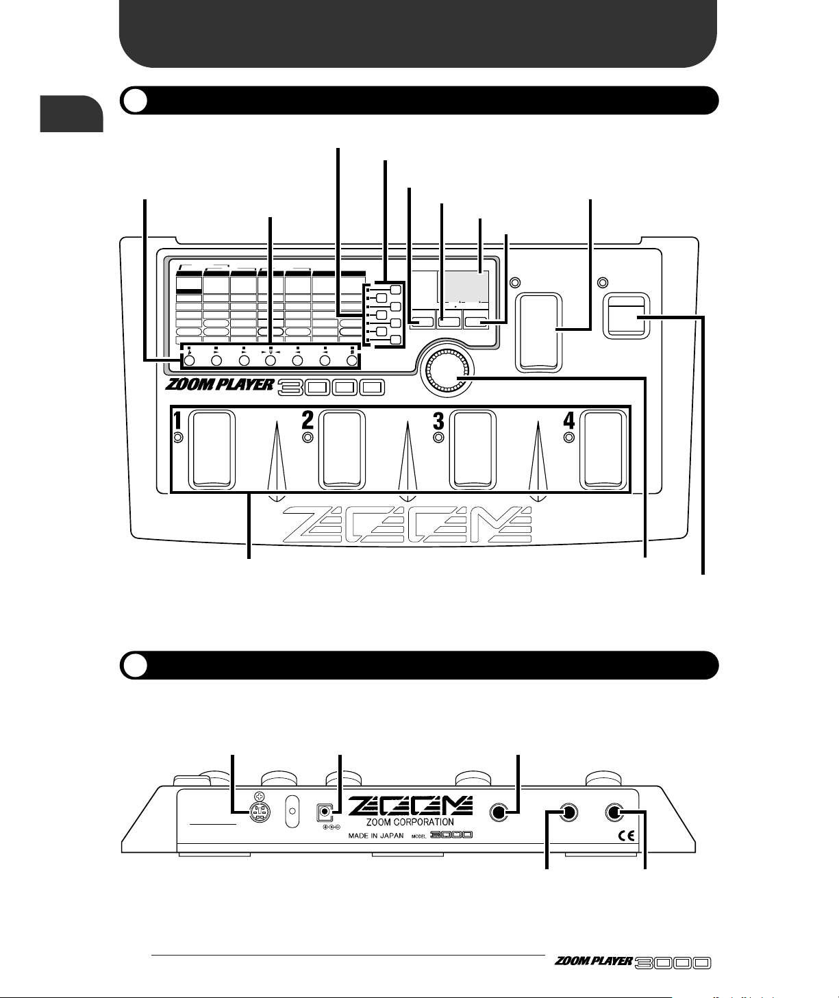
FUNCTION switch
BANK switch
Foot switches 1– 4
Display
EDIT (CANCEL) key
GROUP key
STORE key
Parameter Select keys
Parameter LEDs
VALUE knob
Module LEDs
Module Select keys
300mA
DC9V OUTPUT
(PHONES)
MIC IN INPUT
REMOTE IN
SERIAL NO.
OUTPUT (PHONES) jack
GUITAR INPUT jack MIC INPUT jack
DC INPUT (AC adapter) jack
REMOTE jack
Page 5
3 ●
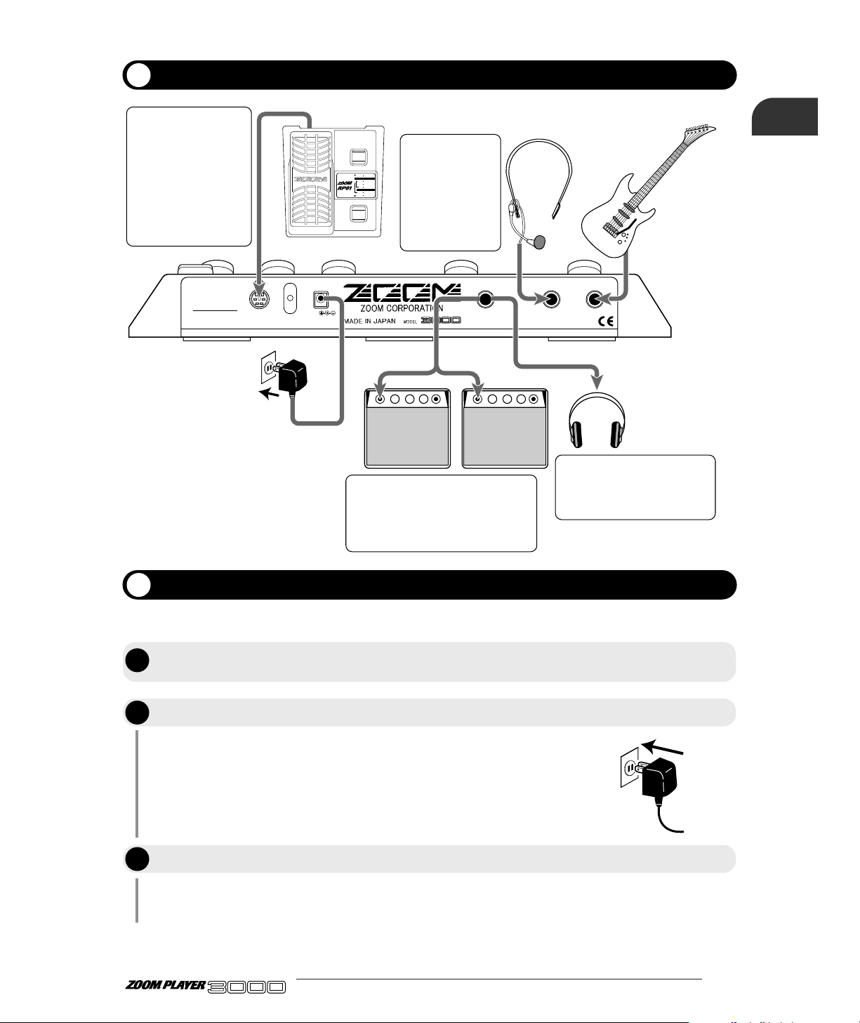
Connect the accessory AC adapter to the DC INPUT jack. The power to
the 3000 is ON when the AC adapter is plugged into a power outlet.
Adjust the volume of the musical instrument and the amplifier while
playing the instrument.
300mA
DC9V OUTPUT
(PHONES)
MIC IN INPUT
REMOTE IN
SERIAL NO.
PHONES OUT
MIC IN INPUT
REMOTE IN
OUTPUT
DC INPUT
Guitaramplifier
Headphones
AC adapter
Guitar
HM01
RP01
When using the optional
remote pedal RP01, use the
remote cable supplied with
the RP01 to connect the
REMOTE OUT jack of the
RP01 to the REMOTE IN
jack of the 3000. Power for
the remote pedal will be
supplied by the 3000.
Other remote cables
available as options (RC05,
RC10) cannot be used.
When using a
microphone for the
TALKING BOX
effect, connect it to
the MIC IN jack. The
optional headset
microphone HM01 or
another dynamic
microphone can be
used.
A pair of stereo headphones can be
connected to the OUTPUT
(PHONES) jack. If the volume level
from the headphones is low, use
phones with low impedance.
When using the 3000 with one guitar
amplifier, make the connection with a
mono cable. When using two guitar
amplifiers, a stereo Y cable is required. The
use of two amplifiers will result in
impressive wide sound for stereo effects.
PEDAL SW
MODE
SELECT
MONITOR
STATUS
MODE DELECT
PEDAL-WAH ON/OFF(PEDAL SW)
DELAY MODE
(PEDAL SW TRIGGER)
RTM MODE
VOLUME ASSIGN
PEDAL-PITCH ON/OFF(PEDAL SW)
Getting Connected
Before Playing
STEP
1
Cut the power to the amplifier, turn the volume down to its minimum level, and
connect the 3000 correctly to the musical instrument and amplifier
Power up the 3000.
Switch ON the power to the amplifier.
ADVANCED GUITAR EFFECTS PROCESSOR
Names of Parts
After completing connection, the volume has to be adjusted according to the following procedure.
STEP
STEP
2
3
Page 6
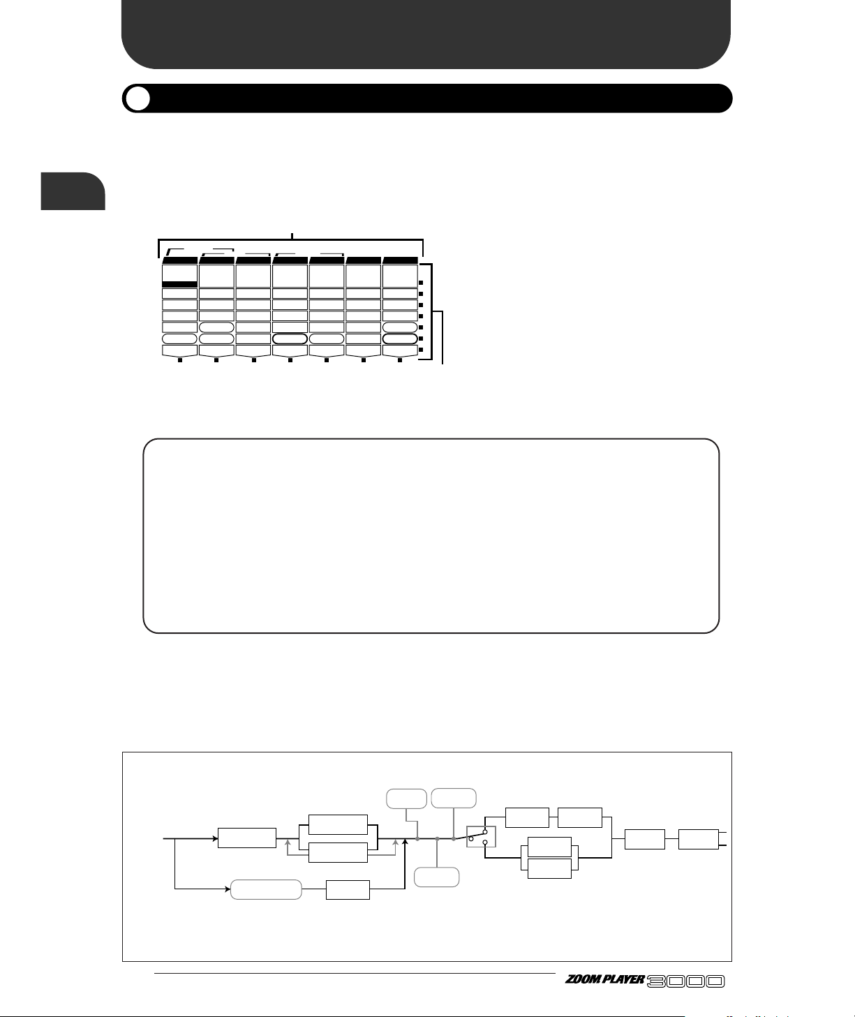
The 3000 is a multi-effect processor featuring seven effect modules (effect blocks). Each effect module works
as a single effect, equivalent to a compact effect device. In other words, the 3000 can be thought of as
functioning in the same way as seven compact effect devices linked together.A compact effect device comes
with knobs for adjusting the type of effect and depth. Similarly, the effect modules have parameters that
determine the type of effect and depth.
Take a look at the top panel of the 3000. At
the top left, you will see the effect modules
(PRE DRIVE - REVERB) arranged in a
horizontal row. The various parameters (1 -
7) which together form the effect module are
listed vertically under the module name.
(Some parameters are independent of effect
modules, and some are general parameters
which work on the entire 3000.)
The 3000 effect modules are of the following types:
• PRE DRIVE This effect module provides light distortion and also includes settings for the talking box
effect for use with a microphone (4 effect types).
• MAIN DRIVE This effect module provides hard distortion and high-gain sound effects. Settings for the
acoustic guitar simulator are also part of this module (8 effect types).
• EQ The built-in three-band equalizer allows separate boost or cut in the low, mid, and high
frequency range. Phaser and wah settings also belong to this module (4 effect types).
• EFFECT1 This is the pitch shifter effect module (5 effect types).
• EFFECT2 This is the modulation effect module (6 effect types).
• DELAY This is the delay effect module (3 effect types).
• REVERB This is the reverb effect module (5 effect types).
All effect modules have several effect types, that is variations which result in different sound. These are called
"effect type". One effect type can be selected for each effect module.
The following diagram shows the signal flow in the 3000, and the effect types that can be selected for
each effect module.
● 4
Introducing the 3000
Introducing the 3000
Outline
ADVANCED GUITAR EFFECTS PROCESSOR
1.COMP
2.BOOSTER
3.OVERDRIVE
4.TALKING BOX
Sens/Gain
(Talking Gain)
Attack/Tone
(Talking Mode)
Level
(MIC Level)
VOLUME RTM
PRE DRIVE RTM
Gain/Top
Tone/Body
Level
ZNR
POSITION
MAIN DRIVE RTM
High/Depth
Midf/Rate/Sens
MidG/Reso
Low/Stage/Inv
Level
EQ RTM
Pitch/Key
Tone/Scale/Time
Shift/Mode/Dly
Bal/Mix
Amp Sim Mode
EFFECT1 RTM
Pitch/Key/Depth
Fine/Scale/Rate
Shift/Mode
Bal/Mix/Peak
SERI/PARA
EFFECT2 RTM
Time(x100mS)
Time(x1mS)
Feedback
Mix
SEAMLESS
DELAY RTM
Time
Tone/FB
Mix
Patch Level
FUNCTION Mode
REVERB RTM
1.OD
3.DIST
5.GRU
7.
METAL
1.3-BAND EQ
2.PHASE
3.PEDAL-WAH
4.AUTO-WAH
1.PITCH
3.DETUNE
4.PEDAL-PITCH
5.STRING
2.HPS 1.HALL1
3.ROOM 1
4.ROOM 2
5.PP-DELAY
2.HALL21.PITCH
3.CHO
5.TREM/PAN
6.RING MOD
1.NORMAL
2.ANALOG
3.HOLD
2.HPS
4.FLG
2.B-OD
4.FUZZ
6.LEAD
8.ACO
PRE DRIVE MAIN DRIVE EQ EFFECT 1 EFFECT 2 DELAY REVERB
TALKING BOX
POSITION SERI/PARA SEAMLESS
Parameters
Effect modules
PRE DRIVE
EQ
EQ
MAIN DRIVE
TALKING BOX
Amp Sim
VOLUME
EFFECT1 EFFECT2
EFFECT1
EFFECT2
DELAY REVERB
P1– P9
SERI/PARA
*1 *1
*3
*2
Sr
*1 The MAIN DRIVE module and EQ effect module
can be connected in three different ways:
parallel connection, serial connection in the order
MAIN DRIVE ➝ EQ, or serial connection in the
order EQ ➝ MAIN DRIVE.
*2 The EFFECT1 module and EFFECT2 module can
be connected in two different ways: parallel or
serial.
*3 When the TALKING BOX effect has been selected
for the PRE DRIVE module, the MAIN DRIVE
module cannot be used, and the signal is sent
directly to the EQ module.
ZNR
Page 7
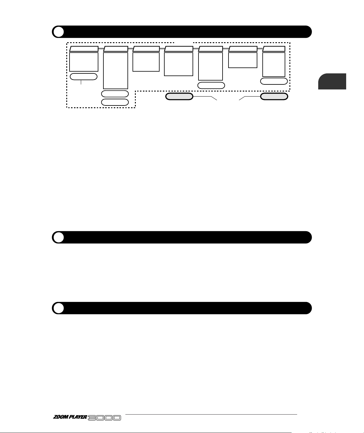
Internal settings for the 3000 can be stored in memory and retrieved from memory in units called
"patches".
A patch is a combination of up to seven effect modules. The patch comprises the parameter settings for
the effect modules, as well as information about ZNR settings, signal routing, etc. The section enclosed
by a dotted line in the above illustration is a patch.
The storage for patches in the 3000 accommodates two types of groups, the USER group that can be
freely created, altered and stored by the user, and the read-only PRESET group that is factory-defined.
Each group supports 40 types of patches, for a storage total of 80. When using the 3000, you can call up
these patches instantly by pressing the foot switch on the panel.
Also, the parameters comprising the patches can be adjusted, and stored in the USER group. In the 3000,
patches are invoked in sets of four, and patches can be changed by using the Foot Switches. These sets of
four patches are called "banks". The USER group and the PRESET group each have banks numbered
from 0 through 9. To select a patch, first switch to the appropriate bank number and then select the
desired patch.
Besides the parameters for individual effect modules, the 3000 also has global parameters which work on
all patches.
When a global parameter is adjusted, its effect will remain even when the patch is switched. However, if
the unit is turned off without storing a patch, the global parameter setting will revert to the previous
value. When wishing to keep the new global parameter setting, choose any patch from the USER group
and store it, as described on page 17.
The workings of the 3000 can be divided into major function categories according to their purpose. These
functions are called "modes". The 3000 has the following four modes:
• Play mode For performance In this mode, you perform by selecting a patch and using an effect.
You can turn the effect sound off temporarily, and use the tuning function in this
mode.
• Manual mode In this mode, effect modules can be switched on and off individually, using the
BANK switch and Foot Switches 1 - 4 on the top panel. This is suitable for use
during a performance.
• Edit mode In this mode, the effect parameters of the currently selected patch can be edited
(changed) by the user. Global parameters are also set in this mode.
• Special mode This mode serves for initializing the 3000. USER group settings and patches can be
selectively returned to the factory default.
5 ●
1.COMP
2.BOOSTER
3.OVERDRIVE
4.TALKING BOX
ZNR
POSITION
Amp Sim Mode
SERI/PARA
Patch Level
FUNCTION Mode
1.OD
2.B-OD
3.DIST
4.FUZZ
5.GRU
6.LEAD
7.
METAL
8.ACO
1.3-BAND EQ
2.PHASE
3.PEDAL-WAH
4.AUTO-WAH
1.PITCH
2.HPS
3.DETUNE
4.PEDAL-PITCH
5.STRING
1.HALL1
2.HALL2
3.ROOM 1
4.ROOM 2
5.PP-DELAY
1.PITCH
2.HPS
3.CHO
4.FLG
5.TREM/PAN
6.RING MOD
1.NORMAL
2.ANALOG
3.HOLD
PRE DRIVE MAIN DRIVE EQ EFFECT 1 EFFECT 2 DELAY REVERB
VOLUME RTM
Patch Parameter
Global Parameters
Patch
Patches and Parameters
Global Parameters
Operation Modes
ADVANCED GUITAR EFFECTS PROCESSOR
Introducing the 3000
Page 8
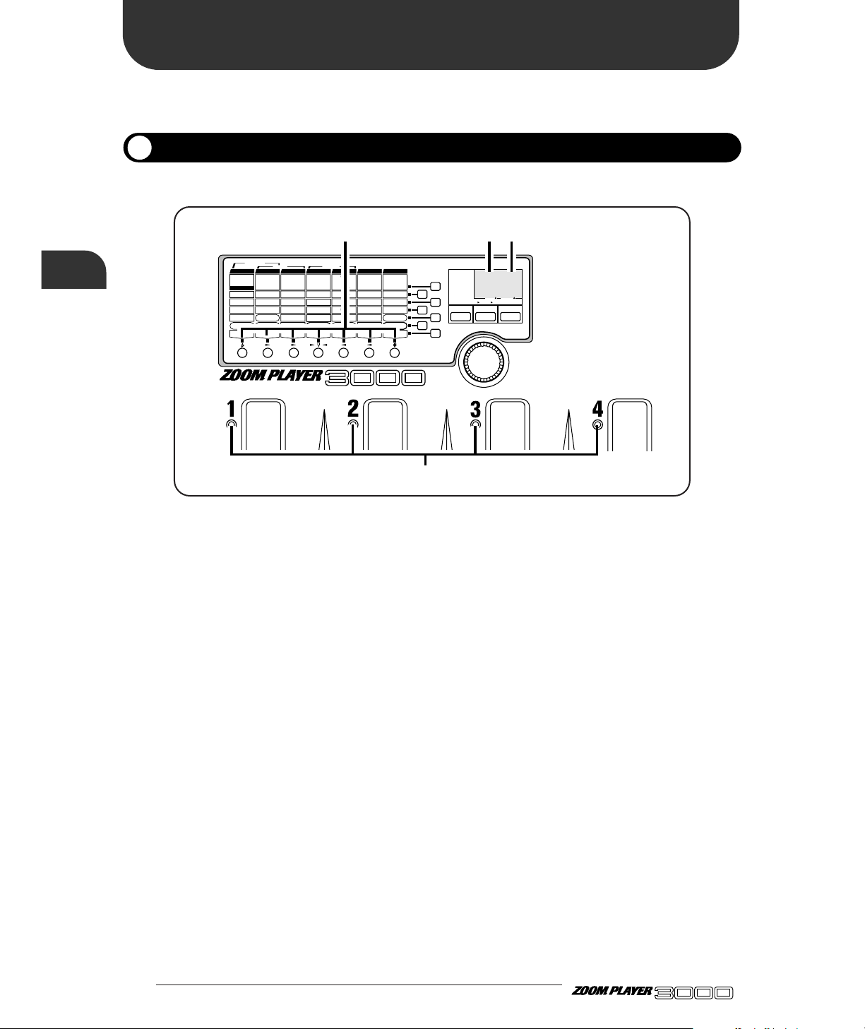
The Play mode is for selecting a patch and playing. When you power up the 3000, it automatically
activates in Play mode, and the USER group's Bank 0, Patch Number 1 is selected.
In Play mode, the display LEDs on the panel show the following information:
(1) Group
The type of group currently selected is indicated in the left side of the display.
(2) Bank Number
The currently selected bank number is indicated in the right side of the display.
(3) Patch Number
The LED of the Foot Switch 1 - 4 corresponding to the currently selected patch number lights up.
(4) Effect Module ON/OFF
The panel module LEDs light for the effect modules are that is on in the currently selected patch.
● 6
Let's Try Out Some Patches
(Play Mode Operation)
Let's Try Out Some Patches
(Play Mode Operation)
Display for Play Mode Panel
ADVANCED GUITAR EFFECTS PROCESSOR
VALUE
ADVANCED GUITAR EFFECTS PROCESSOR
1.COMP
2.BOOSTER
3.OVERDRIVE
4.TALKING BOX
Sens/Gain
(Talking Gain)
Attack/Tone
(Talking Mode)
Level
(MIC Level)
VOLUME RTM
PRE DRIVE RTM
Gain/Top
Tone/Body
Level
ZNR
POSITION
MAIN DRIVE RTM
High/Depth
Midf/Rate/Sens
MidG/Reso
Low/Stage/Inv
Level
EQ RTM
Pitch/Key
Tone/Scale/Time
Shift/Mode/Dly
Bal/Mix
Amp Sim Mode
EFFECT1 RTM
Pitch/Key/Depth
Fine/Scale/Rate
Shift/Mode
Bal/Mix/Peak
SERI/PARA
EFFECT2 RTM
Time(x100mS)
Time(x1mS)
Feedback
Mix
SEAMLESS
DELAY RTM
Time
Tone/FB
Mix
Patch Level
FUNCTION Mode
REVERB RTM
1.OD
3.DIST
5.GRU
7.
METAL
1.3-BAND EQ
2.PHASE
3.PEDAL-WAH
4.AUTO-WAH
1.PITCH
3.DETUNE
4.PEDAL-PITCH
5.STRING
2.HPS 1.HALL1
3.ROOM 1
4.ROOM 2
5.PP-DELAY
2.HALL21.PITCH
3.CHO
5.TREM/PAN
6.RING MOD
1.NORMAL
2.ANALOG
3.HOLD
2.HPS
4.FLG
2.B-OD
4.FUZZ
6.LEAD
8.ACO
PRE DRIVE MAIN DRIVE EQ EFFECT 1 EFFECT 2 DELAY REVERB
TALKING BOX
POSITION SERI/PARA SEAMLESS
FUNCTION MODE BANK(VALUE
)
EDIT(CANCEL)GROUP STORE
1.MANUAL
2.BANK DOWN
3.DELAY(
TAP&HOLD)
4.BYPASS
5.MUTE
6.RTM
7.VOLUME
PRESETUSER
(BOTH) SEAMLESS
U
P
U O
(1) (2)
(4)
(3)
Page 9
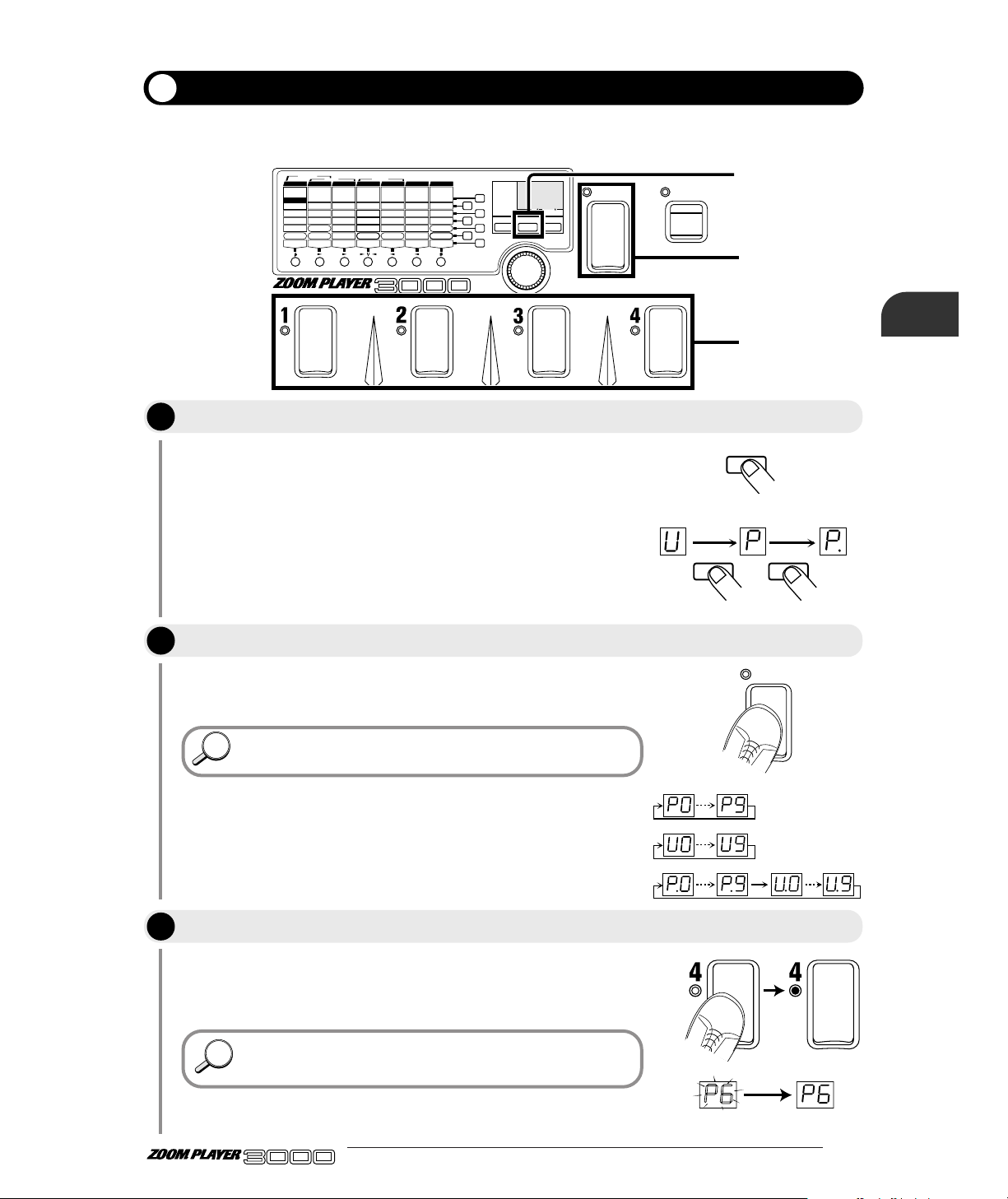
In the Play mode, you can play by choosing one of the patches from among the 80 types (40 USER group
patches plus 40 PRESET patches) in memory.
7 ●
When choosing a patch, first decide which group of patches you want
to use. With each push of the GROUP key, the left side of the display
changes in the following sequence.
• U (USER) Only USER group patches can be used.
• P (PRESET) Only PRESET group patches can be used.
• U. or P. (BOTH) Patches of both USER and PRESET
groups can be used.
Each time you step, you change to the next higher bank number. (The
bank number flashes.)
In this status, the patch will not yet be changed
The LEDs lights for the Foot Switch you stepped on, telling you that a
patch has been selected. Also, the indicated bank number changes
from flashing to constantly lit display.
Here, try switching the patches while you are actually playing
your instrument, and find out what types of patches are stored in
the 3000.
HINTHINT
HINTHINT
BANK
FUNCTION
VALUE
ADVANCED GUITAR EFFECTS PROCESSOR
1.COMP
2.BOOSTER
3.OVERDRIVE
4.TALKING BOX
Sens/Gain
(Talking Gain)
Attack/Tone
(Talking Mode)
Level
(MIC Level)
VOLUME RTM
PRE DRIVE RTM
Gain/Top
Tone/Body
Level
ZNR
POSITION
MAIN DRIVE RTM
High/Depth
Midf/Rate/Sens
MidG/Reso
Low/Stage/Inv
Level
EQ RTM
Pitch/Key
Tone/Scale/Time
Shift/Mode/Dly
Bal/Mix
Amp Sim Mode
EFFECT1 RTM
Pitch/Key/Depth
Fine/Scale/Rate
Shift/Mode
Bal/Mix/Peak
SERI/PARA
EFFECT2 RTM
Time(x100mS)
Time(x1mS)
Feedback
Mix
SEAMLESS
DELAY RTM
Time
Tone/FB
Mix
Patch Level
FUNCTION Mode
REVERB RTM
1.OD
3.DIST
5.GRU
7.
METAL
1.3-BAND EQ
2.PHASE
3.PEDAL-WAH
4.AUTO-WAH
1.PITCH
3.DETUNE
4.PEDAL-PITCH
5.STRING
2.HPS 1.HALL1
3.ROOM 1
4.ROOM 2
5.PP-DELAY
2.HALL21.PITCH
3.CHO
5.TREM/PAN
6.RING MOD
1.NORMAL
2.ANALOG
3.HOLD
2.HPS
4.FLG
2.B-OD
4.FUZZ
6.LEAD
8.ACO
PRE DRIVE MAIN DRIVE E Q EFFECT 1 EFFECT 2 DELAY REVERB
TALKING BOX
POSITION SERI/PARA SEAMLESS
FUNCTION MODE BANK(VALUE
)
EDIT(CANCEL)GROUP STORE
1.MANUAL
2.BANK DOWN
3.DELAY(
TAP&HOLD)
4.BYPASS
5.MUTE
6.RTM
7.VOLUME
PRESETUSER
(BOTH) SEAMLESS
U
P
U O
1
2
3
GROUP
BANK
GROUP=PRESET
GROUP=BOTH
GROUP=USER
USER PRESET BOTH
GROUP GROUP
Selecting a Patch
Press the GROUP key to select the group.
Select a bank by stepping on the BANK switch.
Step on a Foot Switch (1 – 4) to select a patch.
ADVANCED GUITAR EFFECTS PROCESSOR
(Play Mode Operation)
Let's Try Out Some Patches
STEP
1
STEP
2
STEP
3
Page 10
● 8
ADVANCED GUITAR EFFECTS PROCESSOR
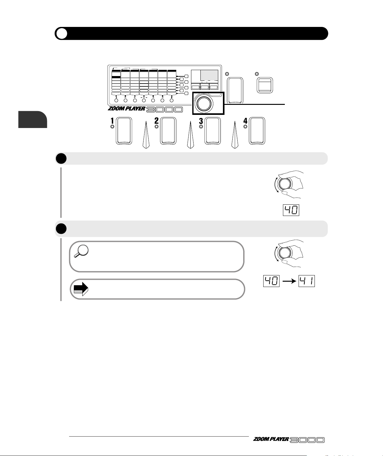
In Play mode, regardless of the selectable patches, the final volume output by the 3000 can be controlled
by the Master Volume.
The display will indicate the current value (1 - 50) of the Master Volume
for one second (default setting: 40).
• The Master Volume setting works in common for all patches. It
cannot be stored for separate patches.
• If you want to change the volume for specific patches, adjust the
patch level in Edit mode. For details, see page 45.
The master level setting cannot be stored. It needs to be adjusted
every time the unit is turned on.
NOTE
HINTHINT
BANK
FUNCTION
VALUE
ADVANCED GUITAR EFFECTS PROCESSOR
1.COMP
2.BOOSTER
3.OVERDRIVE
4.TALKING BOX
Sens/Gain
(Talking Gain)
Attack/Tone
(Talking Mode)
Level
(MIC Level)
VOLUME RTM
PRE DRIVE RTM
Gain/Top
Tone/Body
Level
ZNR
POSITION
MAIN DRIVE RTM
High/Depth
Midf/Rate/Sens
MidG/Reso
Low/Stage/Inv
Level
EQ RTM
Pitch/Key
Tone/Scale/Time
Shift/Mode/Dly
Bal/Mix
Amp Sim Mode
EFFECT1 RTM
Pitch/Key/Depth
Fine/Scale/Rate
Shift/Mode
Bal/Mix/Peak
SERI/PARA
EFFECT2 RTM
Time(x100mS)
Time(x1mS)
Feedback
Mix
SEAMLESS
DELAY RTM
Time
Tone/FB
Mix
Patch Level
FUNCTION Mode
REVERB RTM
1.OD
3.DIST
5.GRU
7.
METAL
1.3-BAND EQ
2.PHASE
3.PEDAL-WAH
4.AUTO-WAH
1.PITCH
3.DETUNE
4.PEDAL-PITCH
5.STRING
2.HPS 1.HALL1
3.ROOM 1
4.ROOM 2
5.PP-DELAY
2.HALL21.PITCH
3.CHO
5.TREM/PAN
6.RING MOD
1.NORMAL
2.ANALOG
3.HOLD
2.HPS
4.FLG
2.B-OD
4.FUZZ
6.LEAD
8.ACO
PRE DRIVE MAIN DRIVE E Q EFFECT 1 EFFECT 2 DELAY REVERB
TALKING BOX
POSITION SERI/PARA SEAMLESS
FUNCTION MODE BANK(VALUE
)
EDIT(CANCEL)GROUP STORE
1.MANUAL
2.BANK DOWN
3.DELAY(
TAP&HOLD)
4.BYPASS
5.MUTE
6.RTM
7.VOLUME
PRESETUSER
(BOTH) SEAMLESS
U
P
U O
1, 2
VALUE
VALUE
Adjusting the Master Volume
Operate the VALUE knob.
While the value is displayed, use the VALUE knob to adjust the volume to the
desired level.
Let's Try Out Some Patches
(Play Mode Operation)
STEP
1
STEP
2
Page 11
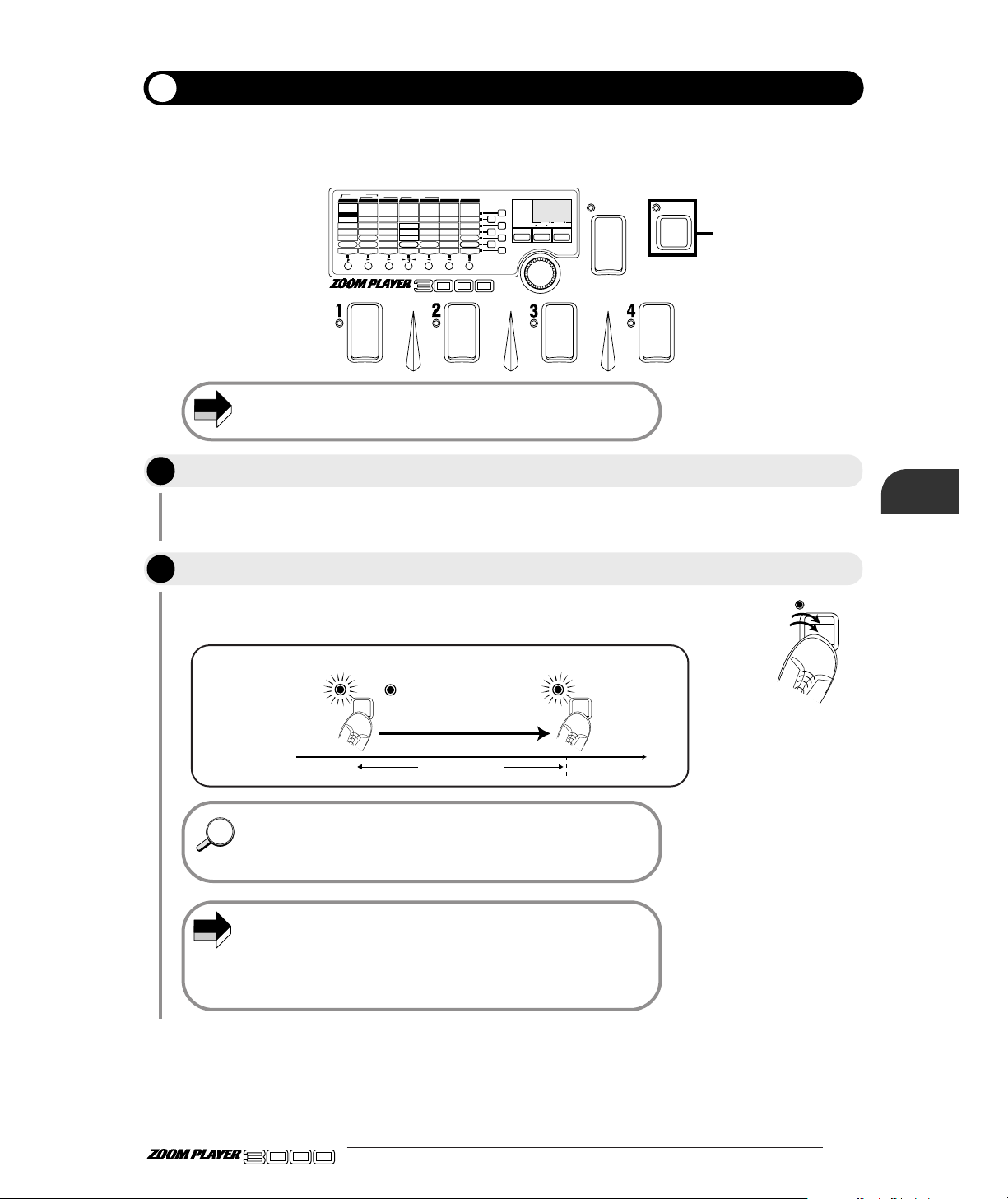
You can switch the 3000 Effect mode OFF temporarily (this is called "bypass"), and monitor the
instrument's direct sound. This is a handy function for checking how the effects are working.
9 ●
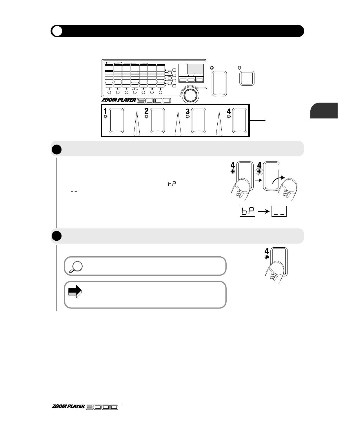
If you lightly step on the Foot Switch and then release your foot within a
second, the 3000 will enter the Bypass status. The LED for the currently
selected patch will flash, and the module LED will light. Also, the
display will indicate the Bypass status
with " ", and then change to
" ".
The 3000 will return to the usual Play mode.
The FUNCTION switch can also be used to activate the Bypass
function. For details, please refer to page 19.
When the FUNCTION switch mode is set to bypass or mute, step 1
is invalid. When not wishing to use the Foot Switches 1 - 4 for
on/off switching of the bypass or mute condition, set the
FUNCTION switch mode to BYPASS or MUTE.
NOTE
HINTHINT
BANK
FUNCTION
VALUE
ADVANCED GUITAR EFFECTS PROCESSOR
1.COMP
2.BOOSTER
3.OVERDRIVE
4.TALKING BOX
Sens/Gain
(Talking Gain)
Attack/Tone
(Talking Mode)
Level
(MIC Level)
VOLUME RTM
PRE DRIVE RTM
Gain/Top
Tone/Body
Level
ZNR
POSITION
MAIN DRIVE RTM
High/Depth
Midf/Rate/Sens
MidG/Reso
Low/Stage/Inv
Level
EQ RTM
Pitch/Key
Tone/Scale/Time
Shift/Mode/Dly
Bal/Mix
Amp Sim Mode
EFFECT1 RTM
Pitch/Key/Depth
Fine/Scale/Rate
Shift/Mode
Bal/Mix/Peak
SERI/PARA
EFFECT2 RTM
Time(x100mS)
Time(x1mS)
Feedback
Mix
SEAMLESS
DELAY RTM
Time
Tone/FB
Mix
Patch Level
FUNCTION Mode
REVERB RTM
1.OD
3.DIST
5.GRU
7.
METAL
1.3-BAND EQ
2.PHASE
3.PEDAL-WAH
4.AUTO-WAH
1.PITCH
3.DETUNE
4.PEDAL-PITCH
5.STRING
2.HPS 1.HALL1
3.ROOM 1
4.ROOM 2
5.PP-DELAY
2.HALL21.PITCH
3.CHO
5.TREM/PAN
6.RING MOD
1.NORMAL
2.ANALOG
3.HOLD
2.HPS
4.FLG
2.B-OD
4.FUZZ
6.LEAD
8.ACO
PRE DRIVE MAIN DRIVE E Q EFFECT 1 EFFECT 2 DELAY REVERB
TALKING BOX
POSITION SERI/PARA SEAMLESS
FUNCTION MODE BANK(VALUE
)
EDIT(CANCEL)GROUP STORE
1.MANUAL
2.BANK DOWN
3.DELAY(
TAP&HOLD)
4.BYPASS
5.MUTE
6.RTM
7.VOLUME
PRESETUSER
(BOTH) SEAMLESS
U
P
U O
1, 2
Release your foot
straight away
Temporarily Switching Effects Off (Bypass Function)
Step on the Foot Switch for the currently selected patch number (the Foot Switch
whose LED is lit) and release your foot straight away.
To release this status, lightly step on and release your foot from the Foot Switch
again, or select another patch.
ADVANCED GUITAR EFFECTS PROCESSOR
(Play Mode Operation)
Let's Try Out Some Patches
STEP
1
STEP
2
Page 12
● 10
ADVANCED GUITAR EFFECTS PROCESSOR
The mute function temporarily turns the output OFF.
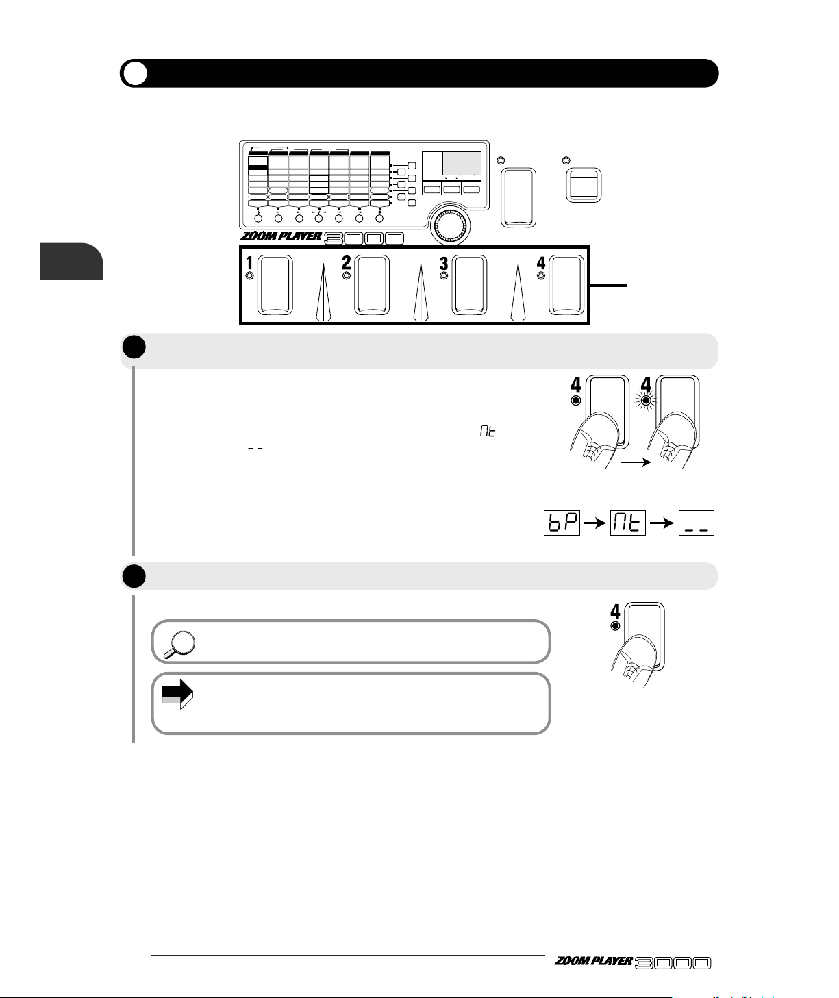
If you have stepped for more than a second on the Foot Switch whose
LED is lit, both effect sound and direct sound will be silenced (muted).
The LED for the currently selected patch will flash, and the module LED
will light. Also, the display will indicate the Mute status with
"", and
then change to " ".
The 3000 will return to the usual Play mode.
The FUNCTION switch can also be used to activate the Mute
function. For details, please refer to page 19.
When the FUNCTION switch mode is set to bypass or mute, step 1
is invalid. When not wishing to use the Foot Switches 1 - 4 for
on/off switching of the bypass or mute condition, set the
FUNCTION switch mode to BYPASS or MUTE.
NOTE
HINTHINT
BANK
FUNCTION
VALUE
ADVANCED GUITAR EFFECTS PROCESSOR
1.COMP
2.BOOSTER
3.OVERDRIVE
4.TALKING BOX
Sens/Gain
(Talking Gain)
Attack/Tone
(Talking Mode)
Level
(MIC Level)
VOLUME RTM
PRE DRIVE RTM
Gain/Top
Tone/Body
Level
ZNR
POSITION
MAIN DRIVE RTM
High/Depth
Midf/Rate/Sens
MidG/Reso
Low/Stage/Inv
Level
EQ RTM
Pitch/Key
Tone/Scale/Time
Shift/Mode/Dly
Bal/Mix
Amp Sim Mode
EFFECT1 RTM
Pitch/Key/Depth
Fine/Scale/Rate
Shift/Mode
Bal/Mix/Peak
SERI/PARA
EFFECT2 RTM
Time(x100mS)
Time(x1mS)
Feedback
Mix
SEAMLESS
DELAY RTM
Time
Tone/FB
Mix
Patch Level
FUNCTION Mode
REVERB RTM
1.OD
3.DIST
5.GRU
7.
METAL
1.3-BAND EQ
2.PHASE
3.PEDAL-WAH
4.AUTO-WAH
1.PITCH
3.DETUNE
4.PEDAL-PITCH
5.STRING
2.HPS 1.HALL1
3.ROOM 1
4.ROOM 2
5.PP-DELAY
2.HALL21.PITCH
3.CHO
5.TREM/PAN
6.RING MOD
1.NORMAL
2.ANALOG
3.HOLD
2.HPS
4.FLG
2.B-OD
4.FUZZ
6.LEAD
8.ACO
PRE DRIVE MAIN DRIVE E Q EFFECT 1 EFFECT 2 DELAY REVERB
TALKING BOX
POSITION SERI/PARA SEAMLESS
FUNCTION MODE BANK(VALUE
)
EDIT(CANCEL)GROUP STORE
1.MANUAL
2.BANK DOWN
3.DELAY(
TAP&HOLD)
4.BYPASS
5.MUTE
6.RTM
7.VOLUME
PRESETUSER
(BOTH) SEAMLESS
U
P
U O
1, 2
Keep your foot more than
one second
Temporarily Turning the Sound Off (Mute Function)
Step on the Foot Switch whose LED is currently lit, keep your foot pressed on the
switch for a moment, and then release it.
To release this status, step on the Foot Switch again, or select another patch.
Let's Try Out Some Patches (Play
Mode Operation)
STEP
1
STEP
2
Page 13
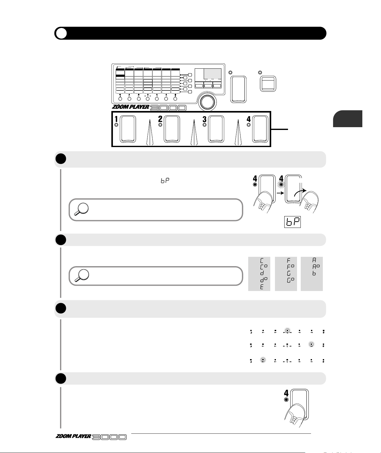
The 3000 will enter the Bypass status, and you can use the autotuner
function. The display will indicate
"", and the module LEDs will
light.
The autotuner function can be used when the 3000 is in Mute
status. This is handy for tuning on stage when you do not want to
produce the sound externally.
The display shows the tone closest to the current pitch. Tune the guitar
until it matches the desired tone.
For tuning an electric bass, use 12F harmonics and tune with the
sound an octave higher.
When the tuner function is ON, the module LED works as a meter,
measuring the accuracy of the tuning. If the pitch matches accurately,
the middle LED (the EFF1 module LED) lights.
The 3000 returns to the Play mode.
HINTHINT
HINTHINT
The 3000 supports a chromatic autotuner function. This function can be used automatically in Bypass or
Mute status.
11 ●
BANK
FUNCTION
VALUE
ADVANCED GUITAR EFFECTS PROCESSOR
1.COMP
2.BOOSTER
3.OVERDRIVE
4.TALKING BOX
Sens/Gain
(Talking Gain)
Attack/Tone
(Talking Mode)
Level
(MIC Level)
VOLUME RTM
PRE DRIVE RTM
Gain/Top
Tone/Body
Level
ZNR
POSITION
MAIN DRIVE RTM
High/Depth
Midf/Rate/Sens
MidG/Reso
Low/Stage/Inv
Level
EQ RTM
Pitch/Key
Tone/Scale/Time
Shift/Mode/Dly
Bal/Mix
Amp Sim Mode
EFFECT1 RTM
Pitch/Key/Depth
Fine/Scale/Rate
Shift/Mode
Bal/Mix/Peak
SERI/PARA
EFFECT2 RTM
Time(x100mS)
Time(x1mS)
Feedback
Mix
SEAMLESS
DELAY RTM
Time
Tone/FB
Mix
Patch Level
FUNCTION Mode
REVERB RTM
1.OD
3.DIST
5.GRU
7.
METAL
1.3-BAND EQ
2.PHASE
3.PEDAL-WAH
4.AUTO-WAH
1.PITCH
3.DETUNE
4.PEDAL-PITCH
5.STRING
2.HPS 1.HALL1
3.ROOM 1
4.ROOM 2
5.PP-DELAY
2.HALL21.PITCH
3.CHO
5.TREM/PAN
6.RING MOD
1.NORMAL
2.ANALOG
3.HOLD
2.HPS
4.FLG
2.B-OD
4.FUZZ
6.LEAD
8.ACO
PRE DRIVE MAIN DRIVE E Q EFFECT 1 EFFECT 2 DELAY REVERB
TALKING BOX
POSITION SERI/PARA SEAMLESS
FUNCTION MODE BANK(VALUE
)
EDIT(CANCEL)GROUP STORE
1.MANUAL
2.BANK DOWN
3.DELAY(
TAP&HOLD)
4.BYPASS
5.MUTE
6.RTM
7.VOLUME
PRESETUSER
(BOTH) SEAMLESS
U
P
U O
1, 4
C=
C
#
=
D=
D
#
=
E=
F=
F
#
=
G=
G
#
=
A=
A
#
=
B=
Release your foot
straight away
pitch matches accurately
pitch is sharp
pitch is flat
Tuning Your Guitar (Autotuner Function)
Lightly step on the Foot Switch whose LED is currently lit in the display for Foot
Switches 1 - 4, and release your foot straight away.
Pick a released string.
When the display shows the desired tone, perform fine tuning until the EFFECT1
module LED lights up.
Press the Foot Switch again, or select another patch.
ADVANCED GUITAR EFFECTS PROCESSOR
(Play Mode Operation)
Let's Try Out Some Patches
STEP
1
STEP
2
STEP
3
STEP
4
Page 14
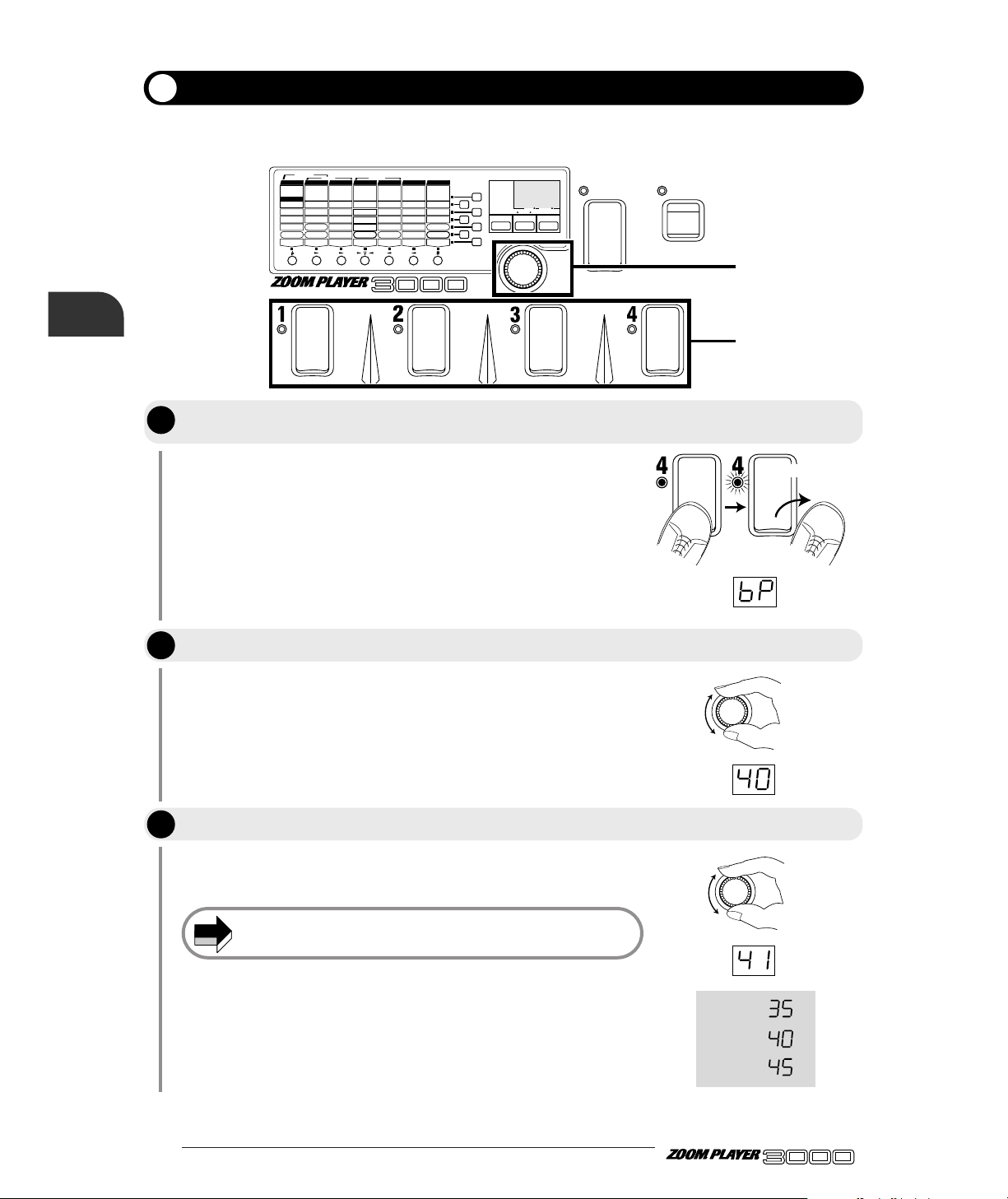
● 12
ADVANCED GUITAR EFFECTS PROCESSOR
Set the internal standard pitch (calibration).
The display will indicate "bP", and the module LEDs will light.
The display will indicate the current calibration value for one second.
Calibration is within the range of "35" (A = 435 Hz) and "45" (A = 445
Hz).
Every time the unit is turned on, the calibration value is reset to
A = 440 Hz.
.
NOTE
BANK
FUNCTION
VALUE
ADVANCED GUITAR EFFECTS PROCESSOR
1.COMP
2.BOOSTER
3.OVERDRIVE
4.TALKING BOX
Sens/Gain
(Talking Gain)
Attack/Tone
(Talking Mode)
Level
(MIC Level)
VOLUME RTM
PRE DRIVE RTM
Gain/Top
Tone/Body
Level
ZNR
POSITION
MAIN DRIVE RTM
High/Depth
Midf/Rate/Sens
MidG/Reso
Low/Stage/Inv
Level
EQ RTM
Pitch/Key
Tone/Scale/Time
Shift/Mode/Dly
Bal/Mix
Amp Sim Mode
EFFECT1 RTM
Pitch/Key/Depth
Fine/Scale/Rate
Shift/Mode
Bal/Mix/Peak
SERI/PARA
EFFECT2 RTM
Time(x100mS)
Time(x1mS)
Feedback
Mix
SEAMLESS
DELAY RTM
Time
Tone/FB
Mix
Patch Level
FUNCTION Mode
REVERB RTM
1.OD
3.DIST
5.GRU
7.
METAL
1.3-BAND EQ
2.PHASE
3.PEDAL-WAH
4.AUTO-WAH
1.PITCH
3.DETUNE
4.PEDAL-PITCH
5.STRING
2.HPS 1.HALL1
3.ROOM 1
4.ROOM 2
5.PP-DELAY
2.HALL21.PITCH
3.CHO
5.TREM/PAN
6.RING MOD
1.NORMAL
2.ANALOG
3.HOLD
2.HPS
4.FLG
2.B-OD
4.FUZZ
6.LEAD
8.ACO
PRE DRIVE MAIN DRIVE E Q EFFECT 1 EFFECT 2 DELAY REVERB
TALKING BOX
POSITION SERI/PARA SEAMLESS
FUNCTION MODE BANK(VALUE
)
EDIT(CANCEL)GROUP STORE
1.MANUAL
2.BANK DOWN
3.DELAY(
TAP&HOLD)
4.BYPASS
5.MUTE
6.RTM
7.VOLUME
PRESETUSER
(BOTH) SEAMLESS
U
P
U O
2, 3
1
VALUE
VALUE
435Hz :
440Hz :
445Hz :
Release your foot
straight away
Adjusting the Standard Pitch of the Tuner (Calibration)
Invoke the Bypass status by lightly stepping on and releasing your foot from the
Foot Switch whose LED is currently lit in the display for Foot Switches 1 - 4.
Operate the VALUE knob.
While the value is displayed, use the VALUE knob to set the desired value.
Let's Try Out Some Patches (Play
Mode Operation)
STEP
1
STEP
2
STEP
3
Page 15
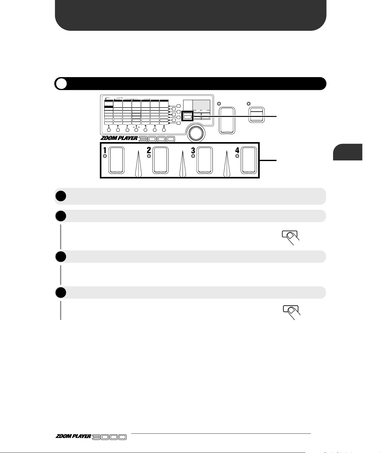
This section describes the basic operation of the Edit mode. The patches of the 3000 are made up from a
variety of parameters that determine the sound as well as parameters that are independent of patches,
such as ZNR sensitivity settings, module connection routing, etc. In the Edit mode, parameters can be
changed to fit your personal preferences. Most global parameters are also set in this mode.
13 ●
The 3000 enters Edit mode, so that you can edit parameters.
The editing methods are explained in detail on the following pages.
The 3000 returns to the Play mode.
BANK
FUNCTION
VALUE
ADVANCED GUITAR EFFECTS PROCESSOR
1.COMP
2.BOOSTER
3.OVERDRIVE
4.TALKING BOX
Sens/Gain
(Talking Gain)
Attack/Tone
(Talking Mode)
Level
(MIC Level)
VOLUME RTM
PRE DRIVE RTM
Gain/Top
Tone/Body
Level
ZNR
POSITION
MAIN DRIVE RTM
High/Depth
Midf/Rate/Sens
MidG/Reso
Low/Stage/Inv
Level
EQ RTM
Pitch/Key
Tone/Scale/Time
Shift/Mode/Dly
Bal/Mix
Amp Sim Mode
EFFECT1 RTM
Pitch/Key/Depth
Fine/Scale/Rate
Shift/Mode
Bal/Mix/Peak
SERI/PARA
EFFECT2 RTM
Time(x100mS)
Time(x1mS)
Feedback
Mix
SEAMLESS
DELAY RTM
Time
Tone/FB
Mix
Patch Level
FUNCTION Mode
REVERB RTM
1.OD
3.DIST
5.GRU
7.
METAL
1.3-BAND EQ
2.PHASE
3.PEDAL-WAH
4.AUTO-WAH
1.PITCH
3.DETUNE
4.PEDAL-PITCH
5.STRING
2.HPS 1.HALL1
3.ROOM 1
4.ROOM 2
5.PP-DELAY
2.HALL21.PITCH
3.CHO
5.TREM/PAN
6.RING MOD
1.NORMAL
2.ANALOG
3.HOLD
2.HPS
4.FLG
2.B-OD
4.FUZZ
6.LEAD
8.ACO
PRE DRIVE MAIN DRIVE EQ EFFECT 1 EFFECT 2 DELAY REVERB
TALKING BOX
POSITION SERI/PARA SEAMLESS
FUNCTION MODE BANK(VALUE
)
EDIT(CANCEL)GROUP STORE
1.MANUAL
2.BANK DOWN
3.DELAY(
TAP&HOLD)
4.BYPASS
5.MUTE
6.RTM
7.VOLUME
PRESETUSER
(BOTH) SEAMLESS
. .
U
P
A 1
2, 4
1
EDIT(CANCEL
)
EDIT(CANCEL
)
Switching between Edit and Play Modes
In the Play mode, choose the patch you want to edit. (This can be from the USER
or PRESET group.)
Press the EDIT key.
Perform editing.
When you have finished editing, press the EDIT key again.
ADVANCED GUITAR EFFECTS PROCESSOR
(Edit Mode Operation)
Changing the Patch Sound
Changing the Patch Sound
(Edit Mode Operation)
STEP
STEP
1
2
STEP
3
STEP
4
Page 16
In Edit mode, the panel displays the following information:
(1) Effect module ON/OFF
When the effect modules are ON in a patch, their corresponding module LEDs light.
(2) Parameter type
On the top panel of the 3000, effect modules are arranged horizontally and effect parameters for the
various modules are listed vertically (including patch parameters and global parameters).
(3) Currently selected parameter
The parameter at the point where the lines marked by the flashing module LED and flashing
parameter LED cross is the parameter that is currently selected for editing. When an effect module is
selected that is currently off, the flashing interval of the module LED changes (the off time becomes
longer).
(4) Parameter value
The value of the parameter currently selected for editing is displayed. When the selected effect
module is off, only "
--" is displayed.
Depending on the type selected for the effect module, some parameters may have no setting item. When
such a parameter is selected, the display shows "
-.-.". For information on effect types and parameters,
please refer to page 36.
● 14
Changing the Patch Sound
(Edit Mode Operation)
Panel Display in Edit Mode
ADVANCED GUITAR EFFECTS PROCESSOR
1.COMP
2.BOOSTER
3.OVERDRIVE
4.TALKING BOX
Sens/Gain
(Talking Gain)
Attack/Tone
(Talking Mode)
Level
(MIC Level)
VOLUME RTM
PRE DRIVE RTM
Gain/Top
Tone/Body
Level
ZNR
POSITION
MAIN DRIVE RTM
High/Depth
Midf/Rate/Sens
MidG/Reso
Low/Stage/Inv
Level
EQ RTM
Pitch/Key
Tone/Scale/Time
Shift/Mode/Dly
Bal/Mix
Amp Sim Mode
EFFECT1 RTM
Pitch/Key/Depth
Fine/Scale/Rate
Shift/Mode
Bal/Mix/Peak
SERI/PARA
EFFECT2 RTM
Time(x100mS)
Time(x1mS)
Feedback
Mix
SEAMLESS
DELAY RTM
Time
Tone/FB
Mix
Patch Level
FUNCTION Mode
REVERB RTM
1.OD
3.DIST
5.GRU
7.
METAL
1.3-BAND EQ
2.PHASE
3.PEDAL-WAH
4.AUTO-WAH
1.PITCH
3.DETUNE
4.PEDAL-PITCH
5.STRING
2.HPS 1.HALL1
3.ROOM 1
4.ROOM 2
5.PP-DELAY
2.HALL21.PITCH
3.CHO
5.TREM/PAN
6.RING MOD
1.NORMAL
2.ANALOG
3.HOLD
2.HPS
4.FLG
2.B-OD
4.FUZZ
6.LEAD
8.ACO
PRE DRIVE MAIN DRIVE EQ EFFECT 1 EFFECT 2 DELAY REVERB
TALKING BOX
POSITION SERI/PARA SEAMLESS
FUNCTION MODE BANK(VALUE
)
EDIT(CANCEL)GROUP STORE
1.MANUAL
2.BANK DOWN
3.DELAY(TAP&HOLD)
4.BYPASS
5.MUTE
6.RTM
7.VOLUME
PRESETUSER
(BOTH) SEAMLESS
U
P
1 0
(4)
(3)
(1)
Time(x1mS)
Time(x1mS)
(2)
Bal/Mix/Peak
Mix
Peath Level
Bal/Mix/Peak
Mix
Peath Level
SERI/PARA
EFFECT2 RTM
SEAMLESS
DELAY RTM
FUNCTION Mode
REVERB RTM
Effect module on (LED lit)
SERI/PARA
EFFECT2 RTM
SEAMLESS
DELAY RTM
FUNCTION Mode
REVERB RTM
Effect module off (LED out)
When selected effect module is on
Selected
parameter
Pitch/Key/Depth
Fine/Scale/Rate
Shift/Mode
Bal/Mix/Peak
SERI/PARA
EFFECT2 RTM
Time(x100mS)
Time(x1mS)
Feedback
Mix
SEAMLESS
DELAY RTM
Time
Tone/FB
Mix
Patch Level
FUNCTION Mode
REVERB RTM
Effect module on
Flashes at
same rate
- 2
When selected effect module is off
Selected
parameter
Pitch/Key/Depth
Fine/Scale/Rate
Shift/Mode
Bal/Mix/Peak
SERI/PARA
EFFECT2 RTM
Time(x100mS)
Time(x1mS)
Feedback
Mix
SEAMLESS
DELAY RTM
Time
Tone/FB
Mix
Patch Level
FUNCTION Mode
REVERB RTM
OFF interval is
longer
Parameter value
Effect module off
- -
Flashes
Page 17

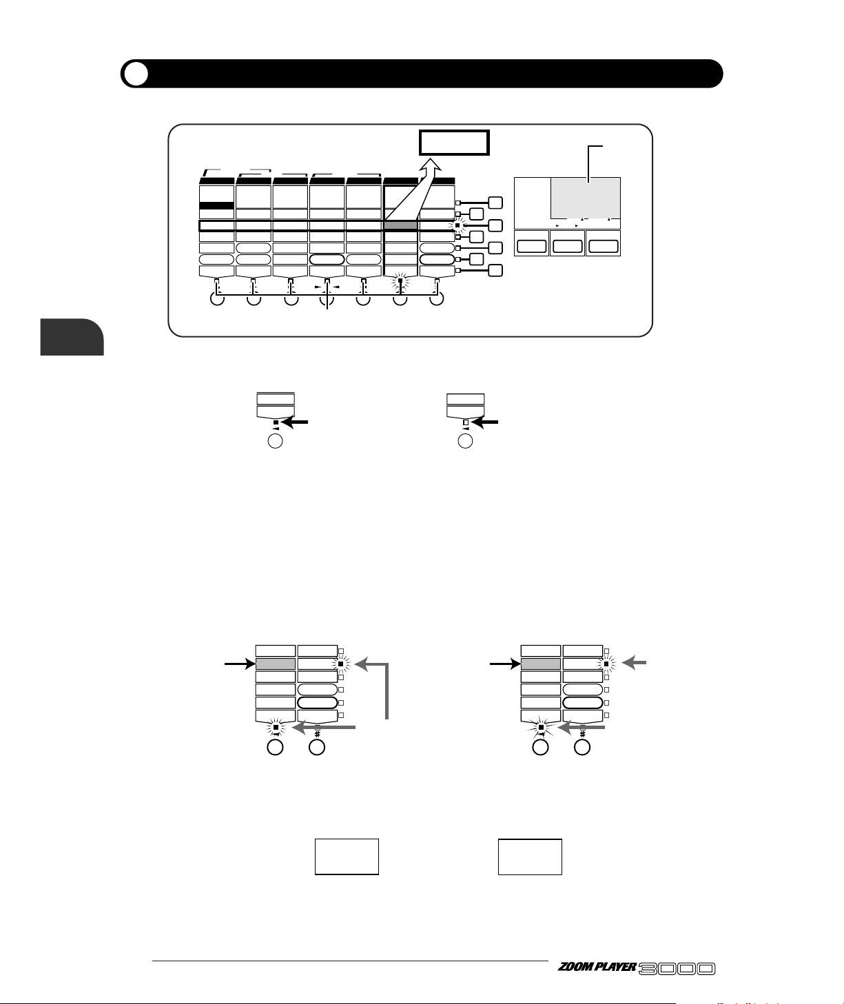
In Edit mode, the effect modules can be switched on or off freely.
15 ●
In Edit mode, the module LEDs light for effect modules that are
currently on. The LED for the module that is selected for editing flashes.
By pressing the MODULE Select key directly under the module LED,
this LED starts to flash.
The MODULE key can be used to toggle the module on or off. When
off, the module LED goes out.
• The module on/off state can be stored as part of a patch, by
performing the store operation as described on page 17.
• In Manual mode, the BANK switch and Foot Switches 1 - 4 can
be used to switch modules on and off. For details, please refer to
page 20.
• In Play mode, modules can be switched on and off by pressing
the Module Select keys.
BANK
FUNCTION
VALUE
ADVANCED GUITAR EFFECTS PROCESSOR
1.COMP
2.BOOSTER
3.OVERDRIVE
4.TALKING BOX
Sens/Gain
(Talking Gain)
Attack/Tone
(Talking Mode)
Level
(MIC Level)
VOLUME RTM
PRE DRIVE RTM
Gain/Top
Tone/Body
Level
ZNR
POSITION
MAIN DRIVE RTM
High/Depth
Midf/Rate/Sens
MidG/Reso
Low/Stage/Inv
Level
EQ RTM
Pitch/Key
Tone/Scale/Time
Shift/Mode/Dly
Bal/Mix
Amp Sim Mode
EFFECT1 RTM
Pitch/Key/Depth
Fine/Scale/Rate
Shift/Mode
Bal/Mix/Peak
SERI/PARA
EFFECT2 RTM
Time(x100mS)
Time(x1mS)
Feedback
Mix
SEAMLESS
DELAY RTM
Time
Tone/FB
Mix
Patch Level
FUNCTION Mode
REVERB RTM
1.OD
3.DIST
5.GRU
7.
METAL
1.3-BAND EQ
2.PHASE
3.PEDAL-WAH
4.AUTO-WAH
1.PITCH
3.DETUNE
4.PEDAL-PITCH
5.STRING
2.HPS 1.HALL1
3.ROOM 1
4.ROOM 2
5.PP-DELAY
2.HALL21.PITCH
3.CHO
5.TREM/PAN
6.RING MOD
1.NORMAL
2.ANALOG
3.HOLD
2.HPS
4.FLG
2.B-OD
4.FUZZ
6.LEAD
8.ACO
PRE DRIVE MAIN DRIVE E Q EFFECT 1 EFFECT 2 DELAY REVERB
TALKING BOX
POSITION SERI/PARA SEAMLESS
FUNCTION MODE BANK(VALUE
)
EDIT(CANCEL)GROUP STORE
1.MANUAL
2.BANK DOWN
3.DELAY(
TAP&HOLD)
4.BYPASS
5.MUTE
6.RTM
7.VOLUME
PRESETUSER
(BOTH) SEAMLESS
U
P
U O
1, 2
Switching Effect Modules On/Off
Use the Module Select keys to select the desired effect module.
Pressing the MODULE Select key once more turns the effect module on or off.
ADVANCED GUITAR EFFECTS PROCESSOR
(Edit Mode Operation)
Changing the Patch Sound
HINTHINT
STEP
1
STEP
2
Page 18

● 16
ADVANCED GUITAR EFFECTS PROCESSOR
You can choose any parameter of an effect module and change the setting and value as desired.
The flashing module moves to the LED for the selected module.
The flashing parameter LED moves to the LED for the selected
parameter.
• When you have switched a module or parameter, the display
changes accordingly.
• The settings of patch parameters and global parameters can
also be changed in the same way.
• The topmost parameter controls the effect type. When the effect
type is changed, the values of other parameters for that module
also change. For the distortion effect types of the PREDRIVE
and MAIN DRIVE modules and for the DELAY module, the
content of the effect parameters does not change.
The current parameter value changes.
For details about the types and functions of parameters of the
effect modules, see page 36 -45 , "Effect Types and Parameters".
The parameter changes made in this way are temporary. If you do
not store the new settings, they will return to the original values
when you return to Play mode and select another patch. (Global
parameters revert to the original setting when the unit is turned off.)
For information on storing patches, please refer to page 17.
NOTE
HINTHINT
BANK
FUNCTION
VALUE
ADVANCED GUITAR EFFECTS PROCESSOR
1.COMP
2.BOOSTER
3.OVERDRIVE
4.TALKING BOX
Sens/Gain
(Talking Gain)
Attack/Tone
(Talking Mode)
Level
(MIC Level)
VOLUME RTM
PRE DRIVE RTM
Gain/Top
Tone/Body
Level
ZNR
POSITION
MAIN DRIVE RTM
High/Depth
Midf/Rate/Sens
MidG/Reso
Low/Stage/Inv
Level
EQ RTM
Pitch/Key
Tone/Scale/Time
Shift/Mode/Dly
Bal/Mix
Amp Sim Mode
EFFECT1 RTM
Pitch/Key/Depth
Fine/Scale/Rate
Shift/Mode
Bal/Mix/Peak
SERI/PARA
EFFECT2 RTM
Time(x100mS)
Time(x1mS)
Feedback
Mix
SEAMLESS
DELAY RTM
Time
Tone/FB
Mix
Patch Level
FUNCTION Mode
REVERB RTM
1.OD
3.DIST
5.GRU
7.
METAL
1.3-BAND EQ
2.PHASE
3.PEDAL-WAH
4.AUTO-WAH
1.PITCH
3.DETUNE
4.PEDAL-PITCH
5.STRING
2.HPS 1.HALL1
3.ROOM 1
4.ROOM 2
5.PP-DELAY
2.HALL21.PITCH
3.CHO
5.TREM/PAN
6.RING MOD
1.NORMAL
2.ANALOG
3.HOLD
2.HPS
4.FLG
2.B-OD
4.FUZZ
6.LEAD
8.ACO
PRE DRIVE MAIN DRIVE E Q EFFECT 1 EFFECT 2 DELAY REVERB
TALKING BOX
POSITION SERI/PARA SEAMLESS
FUNCTION MODE BANK(VALUE
)
EDIT(CANCEL)GROUP STORE
1.MANUAL
2.BANK DOWN
3.DELAY(
TAP&HOLD)
4.BYPASS
5.MUTE
6.RTM
7.VOLUME
PRESETUSER
(BOTH) SEAMLESS
U
P
U O
2
3
1
VALUE
Changing Parameter Settings of Effects
Use the Module Select keys to select an effect module.
Use the Parameter Select keys to select the parameter.
Operate the VALUE knob.
Change other parameters in the same way.
Changing the Patch Sound
(Edit Mode Operation)
HINTHINT
STEP
1
STEP
2
STEP
3
STEP
4
Page 19

As long as you do not store in memory any patches edited in Edit mode, the original status will be
returned when you select another patch. The following paragraphs describe how to store patches.
17 ●
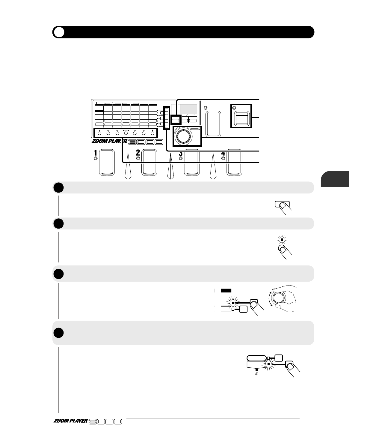
This will invoke the store standby status, and the module LEDs, and
parameter LEDs, will flash. In this status, you can specify the bank
number and patch number of the storage destination.
Even though you can change the parameters of the patches of the
PRESET group, you cannot write over them. Instead, when you
have changed a patch of the PRESET group, the storage destination
can only be "U" (USER group).
You can store in either Play mode or Edit mode.
If you do not make any particular specification, the destination will be
the original patch of the USER group. When store has not been
specified by the PRESET group, the patch is stored in Patch 1, Bank 0
of the USER group.
When you store parameters, the patch data already in the storage
destination will be erased. Check to make sure you do not need the
patch in the storage destination.
If the STORE key was not pressed for the second time, pressing the
EDIT key will abandon the store procedure and return to the
previous condition (before step 1).
NOTE
NOTE
HINTHINT
NOTE
BANK
FUNCTION
VALUE
ADVANCED GUITAR EFFECTS PROCESSOR
1.COMP
2.BOOSTER
3.OVERDRIVE
4.TALKING BOX
Sens/Gain
(Talking Gain)
Attack/Tone
(Talking Mode)
Level
(MIC Level)
VOLUME RTM
PRE DRIVE RTM
Gain/Top
Tone/Body
Level
ZNR
POSITION
MAIN DRIVE RTM
High/Depth
Midf/Rate/Sens
MidG/Reso
Low/Stage/Inv
Level
EQ RTM
Pitch/Key
Tone/Scale/Time
Shift/Mode/Dly
Bal/Mix
Amp Sim Mode
EFFECT1 RTM
Pitch/Key/Depth
Fine/Scale/Rate
Shift/Mode
Bal/Mix/Peak
SERI/PARA
EFFECT2 RTM
Time(x100mS)
Time(x1mS)
Feedback
Mix
SEAMLESS
DELAY RTM
Time
Tone/FB
Mix
Patch Level
FUNCTION Mode
REVERB RTM
1.OD
3.DIST
5.GRU
7.
METAL
1.3-BAND EQ
2.PHASE
3.PEDAL-WAH
4.AUTO-WAH
1.PITCH
3.DETUNE
4.PEDAL-PITCH
5.STRING
2.HPS 1.HALL1
3.ROOM 1
4.ROOM 2
5.PP-DELAY
2.HALL21.PITCH
3.CHO
5.TREM/PAN
6.RING MOD
1.NORMAL
2.ANALOG
3.HOLD
2.HPS
4.FLG
2.B-OD
4.FUZZ
6.LEAD
8.ACO
PRE DRIVE MAIN DRIVE E Q EFFECT 1 EFFECT 2 DELAY REVERB
TALKING BOX
POSITION SERI/PARA SEAMLESS
FUNCTION MODE BANK(VALUE
)
EDIT(CANCEL)GROUP STORE
1.MANUAL
2.BANK DOWN
3.DELAY(
TAP&HOLD)
4.BYPASS
5.MUTE
6.RTM
7.VOLUME
PRESETUSER
(BOTH) SEAMLESS
U
P
U O
1, 3
2
STORE
STORE
BANK
Storing Patches
Press the STORE key.
Using the BANK switch and Foot Switches 1 – 4, specify the patch storage
destination.
Press the STORE key again. This completes the storage operation, and returns the
3000 to the Play mode.
ADVANCED GUITAR EFFECTS PROCESSOR
(Edit Mode Operation)
Changing the Patch Sound
STEP
1
STEP
2
STEP
3
Page 20

● 18
ADVANCED GUITAR EFFECTS PROCESSOR
The FUNCTION switch can be used to quickly activate muting or bypass, or to adjust the volume or
effect parameters in real time.
There are seven modes for the FUNCTION switch which can be selected by the user. To assign a
function, perform the following steps.
The module LED of the REVERB module starts to flash.
FUNCTION Mode is a global parameter which serves to control the
FUNCTION switch. The setting is not affected by the on/off status of
the REVERB module.
Seven modes are available for the FUNCTION switch, as described
below.
1: MANUAL
Toggle between Manual mode and Play mode. For information on
Manual mode, please refer to page 20.
2: BANK DOWN
Switch the bank to the next lower number (opposite direction from
BANK
FUNCTION
VALUE
ADVANCED GUITAR EFFECTS PROCESSOR
1.COMP
2.BOOSTER
3.OVERDRIVE
4.TALKING BOX
Sens/Gain
(Talking Gain)
Attack/Tone
(Talking Mode)
Level
(MIC Level)
VOLUME RTM
PRE DRIVE RTM
Gain/Top
Tone/Body
Level
ZNR
POSITION
MAIN DRIVE RTM
High/Depth
Midf/Rate/Sens
MidG/Reso
Low/Stage/Inv
Level
EQ RTM
Pitch/Key
Tone/Scale/Time
Shift/Mode/Dly
Bal/Mix
Amp Sim Mode
EFFECT1 RTM
Pitch/Key/Depth
Fine/Scale/Rate
Shift/Mode
Bal/Mix/Peak
SERI/PARA
EFFECT2 RTM
Time(x100mS)
Time(x1mS)
Feedback
Mix
SEAMLESS
DELAY RTM
Time
Tone/FB
Mix
Patch Level
FUNCTION Mode
REVERB RTM
1.OD
3.DIST
5.GRU
7.
METAL
1.3-BAND EQ
2.PHASE
3.PEDAL-WAH
4.AUTO-WAH
1.PITCH
3.DETUNE
4.PEDAL-PITCH
5.STRING
2.HPS 1.HALL1
3.ROOM 1
4.ROOM 2
5.PP-DELAY
2.HALL21.PITCH
3.CHO
5.TREM/PAN
6.RING MOD
1.NORMAL
2.ANALOG
3.HOLD
2.HPS
4.FLG
2.B-OD
4.FUZZ
6.LEAD
8.ACO
PRE DRIVE MAIN DRIVE E Q EFFECT 1 EFFECT 2 DELAY REVERB
TALKING BOX
POSITION SERI/PARA SEAMLESS
FUNCTION MODE BANK(VALUE
)
EDIT(CANCEL)GROUP STORE
1.MANUAL
2.BANK DOWN
3.DELAY(
TAP&HOLD)
4.BYPASS
5.MUTE
6.RTM
7.VOLUME
PRESETUSER
(BOTH) SEAMLESS
U
P
U O
1, 5
4
2
3
FUNCTION Mode
REVERB RTM
EDIT(CANCEL
)
Patch Level
FUNCTION Mode
REVERB RTM
VALUE
Assigning a Function to the FUNCTION Switch
Press the EDIT key to activate the Edit mode.
Use the Module Select keys to select the REVERB module.
Use the Parameter Select keys to select parameter 6 (FUNCTION Mode).
Use the VALUE knob to select one of the modes 1 - 7 listed below.
Using the FUNCTION switch
Using the FUNCTION switch
STEP
STEP
1
2
STEP
3
STEP
4
Page 21

19 ●
the BANK switch).
3: DELAY (TAP&HOLD)
Allows tap input of the delay time and for operating the hold delay
feature. For details, please refer to page 21, 22.
4: BYPASS
Toggle the bypass mode on and off. When this mode is selected, the
Foot Switches 1 - 4 cannot be used to control step 1 of the bypass
mode (page 9). When bypass is active, the FUNCTION LED is lit.
5: MUTE
Toggle the mute mode on and off. When this mode is selected, the
Foot Switches 1 - 4 cannot be used to control the mute mode (page
10). When mute is active, the FUNCTION LED is lit.
6: RTM
Control a selected effect parameter in real time. For details, please
refer to page 23.
7: VOLUME
Control the volume. For details, please refer to page 26.
The volume here refers to the input level of the EFFECT1 or
EFFECT2 module. This is different from the patch level or master
level.
The 3000 returns to the Play mode.
This completes the mode setting for the FUNCTION switch.
FUNCTION Mode is a global parameter whose setting does not
change when a different patch is selected. If not stored, the setting
reverts to the previous value when the unit is turned off and then on
again. When wishing to store the setting, select any patch in the
USER group and store it as described on page 17.
NOTE
NOTE
Press the EDIT key once more.
ADVANCED GUITAR EFFECTS PROCESSOR
Using the FUNCTION switch
EDIT(CANCEL
)
STEP
5
Page 22
● 20
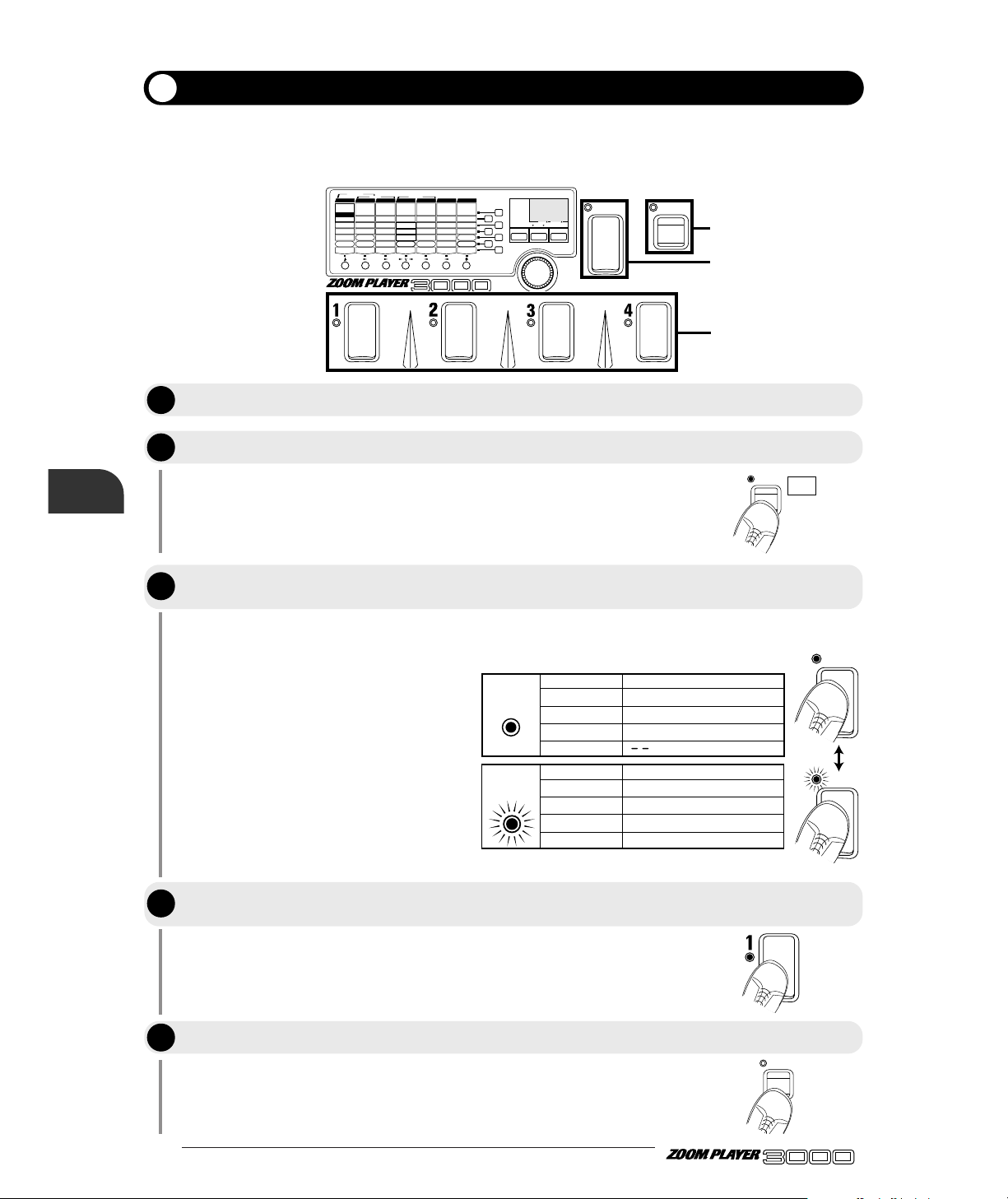
ADVANCED GUITAR EFFECTS PROCESSOR
In Manual mode, effect modules can be switched on and off individually during a performance. When the
FUNCTION Mode parameter is set to "1", the FUNCTION switch can be used to toggle between Manual
mode and regular Play mode. Manual mode operation is described below.
The indication "Mn" appears on the display.
The FUNCTION LED lights up.
In Manual mode, the BANK Switch is used to assign effect modules to
Foot Switches 1 - 4.
When the LED of the BANK switch is lit, the
following effect modules can be assigned to
the Foot Switches 1 - 4.
When the BANK switch was pressed and the
LED flashes, the following modules can be
assigned to the Foot Switches 1 - 4.
The FUNCTION LED goes out and the 3000 returns to Play mode.
BANK
FUNCTION
VALUE
ADVANCED GUITAR EFFECTS PROCESSOR
1.COMP
2.BOOSTER
3.OVERDRIVE
4.TALKING BOX
Sens/Gain
(Talking Gain)
Attack/Tone
(Talking Mode)
Level
(MIC Level)
VOLUME RTM
PRE DRIVE RTM
Gain/Top
Tone/Body
Level
ZNR
POSITION
MAIN DRIVE RTM
High/Depth
Midf/Rate/Sens
MidG/Reso
Low/Stage/Inv
Level
EQ RTM
Pitch/Key
Tone/Scale/Time
Shift/Mode/Dly
Bal/Mix
Amp Sim Mode
EFFECT1 RTM
Pitch/Key/Depth
Fine/Scale/Rate
Shift/Mode
Bal/Mix/Peak
SERI/PARA
EFFECT2 RTM
Time(x100mS)
Time(x1mS)
Feedback
Mix
SEAMLESS
DELAY RTM
Time
Tone/FB
Mix
Patch Level
FUNCTION Mode
REVERB RTM
1.OD
3.DIST
5.GRU
7.
METAL
1.3-BAND EQ
2.PHASE
3.PEDAL-WAH
4.AUTO-WAH
1.PITCH
3.DETUNE
4.PEDAL-PITCH
5.STRING
2.HPS 1.HALL1
3.ROOM 1
4.ROOM 2
5.PP-DELAY
2.HALL21.PITCH
3.CHO
5.TREM/PAN
6.RING MOD
1.NORMAL
2.ANALOG
3.HOLD
2.HPS
4.FLG
2.B-OD
4.FUZZ
6.LEAD
8.ACO
PRE DRIVE MAIN DRIVE EQ EFFECT 1 EFFECT 2 DELAY REVERB
TALKING BOX
POSITION SERI/PARA SEAMLESS
FUNCTION MODE BANK(VALUE
)
EDIT(CANCEL)GROUP STORE
1.MANUAL
2.BANK DOWN
3.DELAY(
TAP&HOLD)
4.BYPASS
5.MUTE
6.RTM
7.VOLUME
PRESETUSER
(BOTH) SEAMLESS
U
P
U O
3
2, 5
4
M n
FUNCTION
FUNCTION
Manual Mode
Set the FUNCTION switch to "1: MANUAL", as described on page 18.
Press the FUNCTION switch while the 3000 is in Play mode.
Use the BANK switch to select effect modules to be assigned to
Foot Switches 1 - 4.
To switch to another patch, press the FUNCTION switch once more.
Using the FUNCTION switch
BANK
BANK
BANK
switch
Foot switch Corresponding effect module
LED lit
1 PRE DRIVE module on/off
2 MAIN DRIVE module on/off
3 EQ module on/off
4
BANK
switch
Foot switch Assignment
LED flashes
1 EFFECT1 module on/off
2 EFFECT2 module on/off
3 DELAY module on/off
REVERB module on/off
4
Use the Foot Switches 1 - 4 to turn the respective effect module on or off.
STEP
STEP
1
2
STEP
3
STEP
STEP
4
5
Page 23
When the FUNCTION Mode parameter is set to "3: DELAY (TAP&HOLD)", the FUNCTION switch
can be used to set the delay time for patches using the NORMAL or ANALOG effect type of the DELAY
module. By using this function, you can easily set the delay time to match the music's tempo.
21 ●
Select a patch which uses the NORMAL or ANALOG effect type of
the DELAY module. To check the effect type, use the Edit mode. For
details, please refer to page 14.
The effect type setting can be checked in the Edit mode. For details,
please refer to page 18, 19.
The 3000 detects the interval in which the FUNCTION switch was
pressed, and the delay time will be set in the DELAY effect module.
When the FUNCTION switch mode is set to "3: DELAY
(TAP&HOLD)", the FUNCTION LED flashes according to the
delay time. This allows you to check the current setting when
making tap input.
• When the FUNCTION switch operation interval exceeds 2000
ms, the original delay time setting remains active.
• When the optional remote pedal RP01 is connected and the
DELAY mode is selected, tap input can be carried out only with
the pedal switch of the RP01. (For details, please refer to page
35.)
HINTHINT
NOTE
BANK
FUNCTION
VALUE
ADVANCED GUITAR EFFECTS PROCESSOR
1.COMP
2.BOOSTER
3.OVERDRIVE
4.TALKING BOX
Sens/Gain
(Talking Gain)
Attack/Tone
(Talking Mode)
Level
(MIC Level)
VOLUME RTM
PRE DRIVE RTM
Gain/Top
Tone/Body
Level
ZNR
POSITION
MAIN DRIVE RTM
High/Depth
Midf/Rate/Sens
MidG/Reso
Low/Stage/Inv
Level
EQ RTM
Pitch/Key
Tone/Scale/Time
Shift/Mode/Dly
Bal/Mix
Amp Sim Mode
EFFECT1 RTM
Pitch/Key/Depth
Fine/Scale/Rate
Shift/Mode
Bal/Mix/Peak
SERI/PARA
EFFECT2 RTM
Time(x100mS)
Time(x1mS)
Feedback
Mix
SEAMLESS
DELAY RTM
Time
Tone/FB
Mix
Patch Level
FUNCTION Mode
REVERB RTM
1.OD
3.DIST
5.GRU
7.
METAL
1.3-BAND EQ
2.PHASE
3.PEDAL-WAH
4.AUTO-WAH
1.PITCH
3.DETUNE
4.PEDAL-PITCH
5.STRING
2.HPS 1.HALL1
3.ROOM 1
4.ROOM 2
5.PP-DELAY
2.HALL21.PITCH
3.CHO
5.TREM/PAN
6.RING MOD
1.NORMAL
2.ANALOG
3.HOLD
2.HPS
4.FLG
2.B-OD
4.FUZZ
6.LEAD
8.ACO
PRE DRIVE MAIN DRIVE EQ EFFECT 1 EFFECT 2 DELAY REVERB
TALKING BOX
POSITION SERI/PARA SEAMLESS
FUNCTION MODE BANK(VALUE
)
EDIT(CANCEL)GROUP STORE
1.MANUAL
2.BANK DOWN
3.DELAY(
TAP&HOLD)
4.BYPASS
5.MUTE
6.RTM
7.VOLUME
PRESETUSER
(BOTH) SEAMLESS
U
P
U O
3
FUNCTION
Step on
Function switch
twice
FUNCTION LED lit flash lit
[ Tap input steps ]
delay time
TIME
Delay Time Tap Input
Set the FUNCTION Mode parameter to "3: DELAY (TAP&HOLD)".
Step on the FUNCTION switch twice, to match the tempo.
ADVANCED GUITAR EFFECTS PROCESSOR
Using the FUNCTION switch
STEP
1
STEP
2
NOTE
Page 24

● 22
ADVANCED GUITAR EFFECTS PROCESSOR
When the FUNCTION Mode parameter is set to "3: DELAY (TAP&HOLD)" and the HOLD effect type
is selected for the DELAY module, the hold delay function can be used. While you keep the FUNCTION
switch depressed, play is sampled and then repeated by the 3000.
The effect type setting can be checked in the Edit mode. For details,
please refer to page 14.
The maximum hold time interval is 2000 ms.
The phrase is sampled for the length of the time that the FUNCTION
switch is pressed. When the switch is released, the phrase is repeated.
When the FUNCTION switch mode is set to "3: DELAY
(TAP&HOLD)", the FUNCTION LED flashes according to the
delay time. This allows you to check the current setting when
making tap input.
If the FUNCTION switch is
pressed for a longer interval
than the hold time, sampling
ends before the switch is
released, and repeat play
starts.
When the FUNCTION switch is pressed, sampling stops and the
FUNCTION LED flashes.
When the optional remote pedal RP01 is connected and DELAY
mode is selected, hold delay can be carried out only with the pedal
switch of the RP01. (For details, please refer to page 35.)
NOTE
HINTHINT
HINTHINT
NOTE
BANK
FUNCTION
VALUE
ADVANCED GUITAR EFFECTS PROCESSOR
1.COMP
2.BOOSTER
3.OVERDRIVE
4.TALKING BOX
Sens/Gain
(Talking Gain)
Attack/Tone
(Talking Mode)
Level
(MIC Level)
VOLUME RTM
PRE DRIVE RTM
Gain/Top
Tone/Body
Level
ZNR
POSITION
MAIN DRIVE RTM
High/Depth
Midf/Rate/Sens
MidG/Reso
Low/Stage/Inv
Level
EQ RTM
Pitch/Key
Tone/Scale/Time
Shift/Mode/Dly
Bal/Mix
Amp Sim Mode
EFFECT1 RTM
Pitch/Key/Depth
Fine/Scale/Rate
Shift/Mode
Bal/Mix/Peak
SERI/PARA
EFFECT2 RTM
Time(x100mS)
Time(x1mS)
Feedback
Mix
SEAMLESS
DELAY RTM
Time
Tone/FB
Mix
Patch Level
FUNCTION Mode
REVERB RTM
1.OD
3.DIST
5.GRU
7.
METAL
1.3-BAND EQ
2.PHASE
3.PEDAL-WAH
4.AUTO-WAH
1.PITCH
3.DETUNE
4.PEDAL-PITCH
5.STRING
2.HPS 1.HALL1
3.ROOM 1
4.ROOM 2
5.PP-DELAY
2.HALL21.PITCH
3.CHO
5.TREM/PAN
6.RING MOD
1.NORMAL
2.ANALOG
3.HOLD
2.HPS
4.FLG
2.B-OD
4.FUZZ
6.LEAD
8.ACO
PRE DRIVE MAIN DRIVE EQ EFFECT 1 EFFECT 2 DELAY REVERB
TALKING BOX
POSITION SERI/PARA SEAMLESS
FUNCTION MODE BANK(VALUE
)
EDIT(CANCEL)GROUP STORE
1.MANUAL
2.BANK DOWN
3.DELAY(
TAP&HOLD)
4.BYPASS
5.MUTE
6.RTM
7.VOLUME
PRESETUSER
(BOTH) SEAMLESS
U
P
U O
3, 4, 5
FUNCTION
FUNCTION
FUNCTION
Using Hold Delay
Set the FUNCTION Mode parameter to "3: DELAY (TAP&HOLD)", as described on
page 18, 19.
Select the HOLD effect type of the DELAY module. If necessary, set the delay time
parameter. This will be the longest interval that can be sampled.
While playing your instrument, press the FUNCTION switch at the point where you
want to start sampling.
Release the FUNCTION switch at the point where you want to end sampling.
When wishing to stop the sampling function, press the FUNCTION switch once more.
Using the FUNCTION switch
Sampling
œ œ œ œ œ œ œ œ œ œ œ œ œ œ œ œ œ œ œ œ œ
・・・
[ Hold delay steps ]
lit lit
FUNCTION LED
flashes
STEP
STEP
1
2
STEP
STEP
3
4
STEP
5
Page 25
The 3000 incorporates a so-called RTM (real-time modulation) function which lets the user change effect
parameters in real time, using the FUNCTION switch. This makes it possible to adjust, for example,
overdrive, distortion, or reverb mix during a performance. It is also possible to control several parameters
simultaneously. The parameter(s) to be affected by RTM, the change distortion, and the change step
width can be set for each patch individually.
To use the RTM function, perform the following steps.
23 ●
If the module is off, press the Module Select key once more to turn it
on.
Which parameter can be controlled depends on the effect type. In the
"Effect Types and Parameters" table on page 36 - 45, the parameter
marked with "
←RTM" can be controlled by RTM.
For example, when the DELAY module is selected, parameter 5 (Mix
(←RTM) can be controlled by RTM.
BANK
FUNCTION
VALUE
ADVANCED GUITAR EFFECTS PROCESSOR
1.COMP
2.BOOSTER
3.OVERDRIVE
4.TALKING BOX
Sens/Gain
(Talking Gain)
Attack/Tone
(Talking Mode)
Level
(MIC Level)
VOLUME RTM
PRE DRIVE RTM
Gain/Top
Tone/Body
Level
ZNR
POSITION
MAIN DRIVE RTM
High/Depth
Midf/Rate/Sens
MidG/Reso
Low/Stage/Inv
Level
EQ RTM
Pitch/Key
Tone/Scale/Time
Shift/Mode/Dly
Bal/Mix
Amp Sim Mode
EFFECT1 RTM
Pitch/Key/Depth
Fine/Scale/Rate
Shift/Mode
Bal/Mix/Peak
SERI/PARA
EFFECT2 RTM
Time(x100mS)
Time(x1mS)
Feedback
Mix
SEAMLESS
DELAY RTM
Time
Tone/FB
Mix
Patch Level
FUNCTION Mode
REVERB RTM
1.OD
3.DIST
5.GRU
7.
METAL
1.3-BAND EQ
2.PHASE
3.PEDAL-WAH
4.AUTO-WAH
1.PITCH
3.DETUNE
4.PEDAL-PITCH
5.STRING
2.HPS 1.HALL1
3.ROOM 1
4.ROOM 2
5.PP-DELAY
2.HALL21.PITCH
3.CHO
5.TREM/PAN
6.RING MOD
1.NORMAL
2.ANALOG
3.HOLD
2.HPS
4.FLG
2.B-OD
4.FUZZ
6.LEAD
8.ACO
PRE DRIVE MAIN DRIVE E Q EFFECT 1 EFFECT 2 DELAY REVERB
TALKING BOX
POSITION SERI/PARA SEAMLESS
FUNCTION MODE BANK(VALUE
)
EDIT(CANCEL)GROUP STORE
1.MANUAL
2.BANK DOWN
3.DELAY(
TAP&HOLD)
4.BYPASS
5.MUTE
6.RTM
7.VOLUME
PRESETUSER
(BOTH) SEAMLESS
U
P
U O
1, 9
11, 12
3, 5, 7
3, 4, 6
2
VALUE
Time
2.HALL2
REVERB
EDIT(CANCEL
)
REVERB RTM
Adjusting Effect Parameters in Real Time (RTM)
Press the EDIT key to activate the Edit mode.
Use the Module Select keys to select the module to be controlled by RTM.
Use the Parameter Select keys to select parameter 1, operate the VALUE knob
and select the effect type.
Refer to the section "Effect Types and Parameters" and check the control target
parameter for the currently selected effect type. Then select this parameter with
the Parameter Select keys.
ADVANCED GUITAR EFFECTS PROCESSOR
Using the FUNCTION switch
STEP
1
STEP
2
STEP
3
STEP
4
Page 26
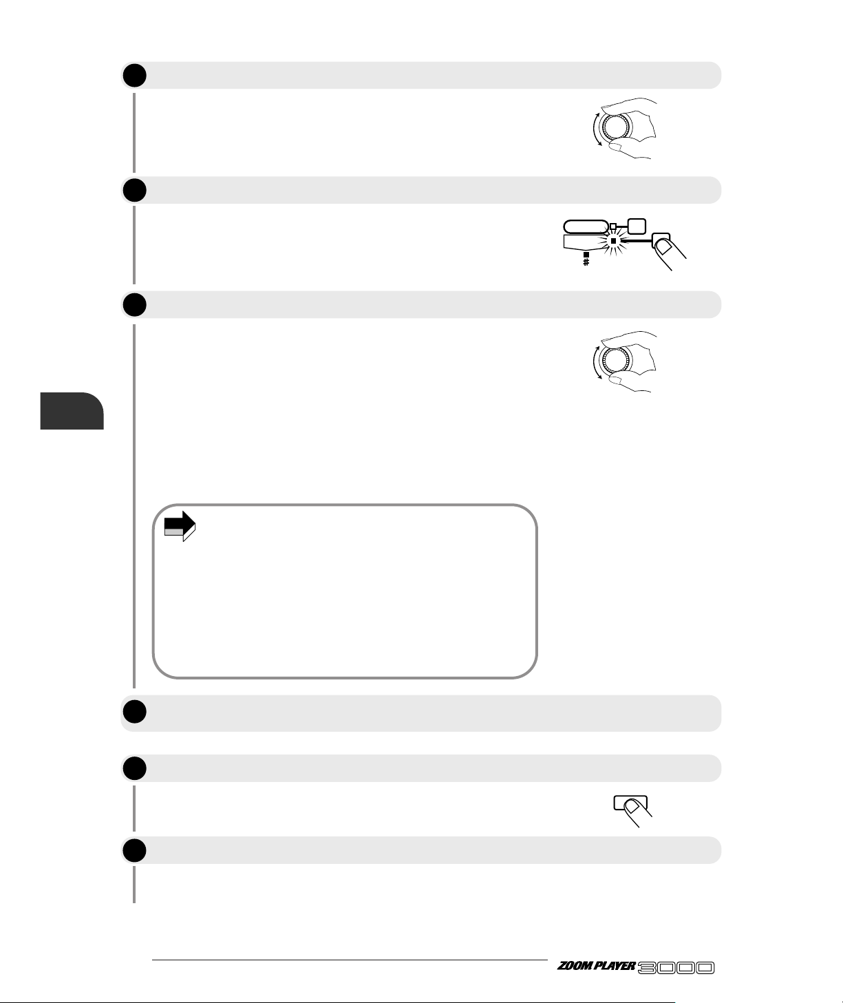
● 24
ADVANCED GUITAR EFFECTS PROCESSOR
The value set in this way becomes the reference setting for RTM.
For every effect module and effect type, parameter 7 sets the RTM
range.
Normally, the RTM parameter uses the value set in step 5 as reference
(0%) and allows adjustment over a range from -10 (-100%) to 0 (0%) to
10 (+100%). If the RTM control target parameter is negative when the
FUNCTION switch is operated, the parameter is adjusted from the
reference value towards negative values. If the target parameter is
positive, it is adjusted from the reference value towards positive values.
For example, if the "Mix (←RTM)" parameter was set to "50" in step 5,
and the RTM parameter is "-5" (-50%), the adjustment range is 50 - 25.
When the parameter is "+5", the adjustment range is 50 - 75.
• The following case is an exception: When the EQ module is
selected in step 2 and the effect type is set to PEDAL- WAH, or
when the EFFECT1 module is selected and the effect type is set
to PEDAL-PITCH (pedal pitch shifter), the RTM parameter
setting range is "dn" (down) or "UP" only.
• It is possible to operate VOLUME RTM together with RTM. This
is controlled by the VOLUME RTM "on" or "of" (off) setting in
the PRE DRIVE effect module.
• The control target parameter cannot be changed beyond the
parameter setting range. For example, if the control target
parameter is already at maximum, setting the RTM parameter to
a positive value has no effect.
If necessary, store the patch as described on page 17.
For details, please refer to the section "Using the FUNCTION switch"
on page 18.
REVERB RTM
VALUE
VALUE
EDIT(CANCEL
)
STEP
Use the VALUE knob to adjust the parameter.
Use the Parameter Select keys to select parameter 7.
If desired, repeat steps 2 through 7 to make the RTM setting for other effect
modules.
Use the VALUE knob to adjust the RTM parameter.
When the setting is completed, press the EDIT key to revert to Play mode.
Set the FUNCTION switch mode to "6: RTM".
Using the FUNCTION switch
NOTE
5
STEP
STEP
6
7
STEP
STEP
STEP
8
9
10
Page 27
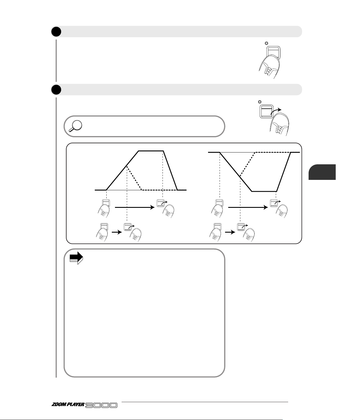
25 ●
The RTM control target parameter changes gradually, causing a
change in the sound quality of the patch. When the end point of the
control range (maximum or minimum) is reached, the parameter
remains constant also if the FUNCTION switch is still depressed.
The RTM control target parameter gradually returns to the original
value.
You can release the FUNCTION switch already before the end of
the control range is reached. The setting will gradually return to
the original value.
• When using RTM control for a distortion effect type of the PRE
DRIVE or MAIN DRIVE module, and the RTM parameter is set
to "dn", pressing the FUNCTION switch will cause the Gain (←
RTM) parameter to change gradually from the reference value
towards the minimum value. When the RTM parameter is set to
"UP", the change will be from the minimum value towards the
reference value. The minimum value in this case depends on the
effect type and Gain (← RTM) parameter settings and may also
be smaller than the Gain (← RTM) parameter minimum value
(1). This is due to the fact that the value is optimized internally
by the 3000.
• When using RTM control for the PEDAL-WAH effect type of the
EQ module, setting the RTM parameter to "dn" will cause a
downward pitch shift and setting the parameter to "UP" will
cause an upward pitch shift when the FUNCTION switch is
pressed. In both cases, releasing the FUNCTION switch will
cause the pitch to return gradually to normal.
• When using RTM control for the PEDAL-PITCH (pedal pitch
shifter) effect type of the EFFECT 1 module, keeping the
FUNCTION switch depressed will cause a gradual upward or
downward shift. The direction is determined by the RTM
parameter ("dn" or "UP").
HINTHINT
Release the FUNCTION switch.
ADVANCED GUITAR EFFECTS PROCESSOR
NOTE
FUNCTION
switch
FUNCTION
switch
Reference value
RTM parameter set to positive value (1 - 10)
Value of
effect parameter
set by RTM
Reference value
Value of
effect parameter
set by RTM
RTM parameter set to negative value (-1 - -10)
STEP
While playing your instrument, press and hold the FUNCTION switch
FUNCTION
FUNCTION
Using the FUNCTION switch
11
STEP
12
Page 28

● 26
ADVANCED GUITAR EFFECTS PROCESSOR
VOLUME RTM is a function for controlling the input level to the EFFECT1 or EFFECT2 module using
the FUNCTION switch. This makes it possible to easily perform fade-out or fade-in during during a
performance.
For details, please refer to the section "Using the FUNCTION switch"
on page 18.
When the FUNCTION switch mode is set to "7: VOLUME", the
FUNCTION switch always operates as volume control, regardless
of the VOLUME RTM setting in the PRE DRIVE module.
If necessary, store the patch as described on page 17.
The volume of the 3000 is gradually reduced to zero. While the
FUNCTION switch is depressed, the FUNCTION LED lights.
The volume here refers to the input level of the EFFECT1 or
EFFECT2 module, not the overall level of the 3000. If for example
long delay with feedback is used, only the original sound is
reduced, and the delay sound still is audible.
The volume gradually returns to the original value.
NOTE
NOTE
BANK
FUNCTION
VALUE
ADVANCED GUITAR EFFECTS PROCESSOR
1.COMP
2.BOOSTER
3.OVERDRIVE
4.TALKING BOX
Sens/Gain
(Talking Gain)
Attack/Tone
(Talking Mode)
Level
(MIC Level)
VOLUME RTM
PRE DRIVE RTM
Gain/Top
Tone/Body
Level
ZNR
POSITION
MAIN DRIVE RTM
High/Depth
Midf/Rate/Sens
MidG/Reso
Low/Stage/Inv
Level
EQ RTM
Pitch/Key
Tone/Scale/Time
Shift/Mode/Dly
Bal/Mix
Amp Sim Mode
EFFECT1 RTM
Pitch/Key/Depth
Fine/Scale/Rate
Shift/Mode
Bal/Mix/Peak
SERI/PARA
EFFECT2 RTM
Time(x100mS)
Time(x1mS)
Feedback
Mix
SEAMLESS
DELAY RTM
Time
Tone/FB
Mix
Patch Level
FUNCTION Mode
REVERB RTM
1.OD
3.DIST
5.GRU
7.
METAL
1.3-BAND EQ
2.PHASE
3.PEDAL-WAH
4.AUTO-WAH
1.PITCH
3.DETUNE
4.PEDAL-PITCH
5.STRING
2.HPS 1.HALL1
3.ROOM 1
4.ROOM 2
5.PP-DELAY
2.HALL21.PITCH
3.CHO
5.TREM/PAN
6.RING MOD
1.NORMAL
2.ANALOG
3.HOLD
2.HPS
4.FLG
2.B-OD
4.FUZZ
6.LEAD
8.ACO
PRE DRIVE MAIN DRIVE E Q EFFECT 1 EFFECT 2 DELAY REVERB
TALKING BOX
POSITION SERI/PARA SEAMLESS
FUNCTION MODE BANK(VALUE
)
EDIT(CANCEL)GROUP STORE
1.MANUAL
2.BANK DOWN
3.DELAY(
TAP&HOLD)
4.BYPASS
5.MUTE
6.RTM
7.VOLUME
PRESETUSER
(BOTH) SEAMLESS
U
P
U O
2
3, 4
EDIT(CANCEL
)
Controlling the Volume in Real Time (VOLUME RTM)
Press the EDIT key to revert to Play mode.
Set the FUNCTION switch mode to "7: VOLUME".
Using the FUNCTION switch
While playing your instrument, press and hold the FUNCTION switch.
Release the FUNCTION switch.
FUNCTION
FUNCTION
STEP
1
STEP
2
STEP
3
STEP
4
Page 29
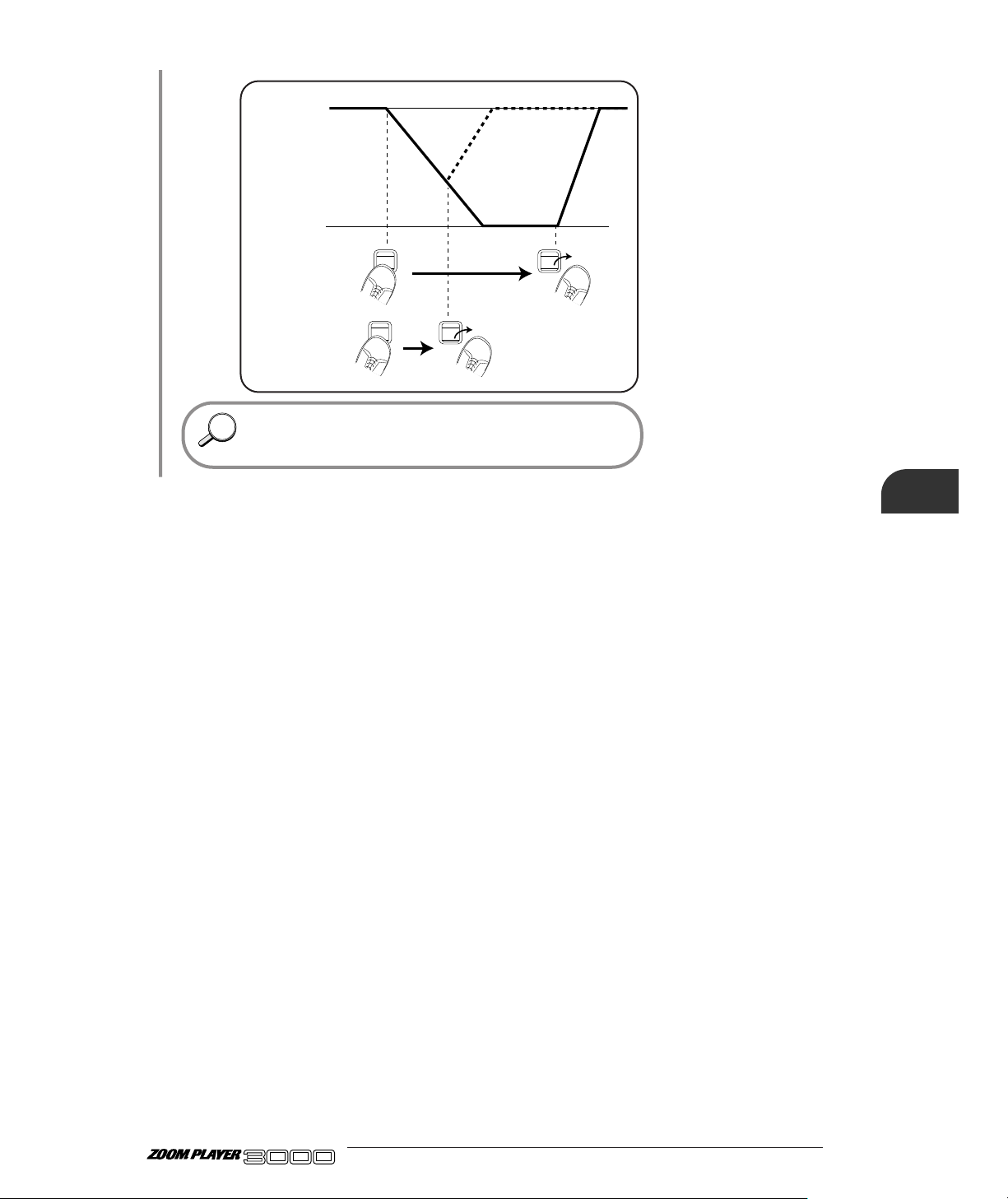
27 ●
You can release the FUNCTION switch before the end of the
control range is reached. The setting will gradually return to the
original value.
FUNCTION
switch
VOLUME
No sound
Reference value
Using the FUNCTION switch
HINTHINT
ADVANCED GUITAR EFFECTS PROCESSOR
Page 30
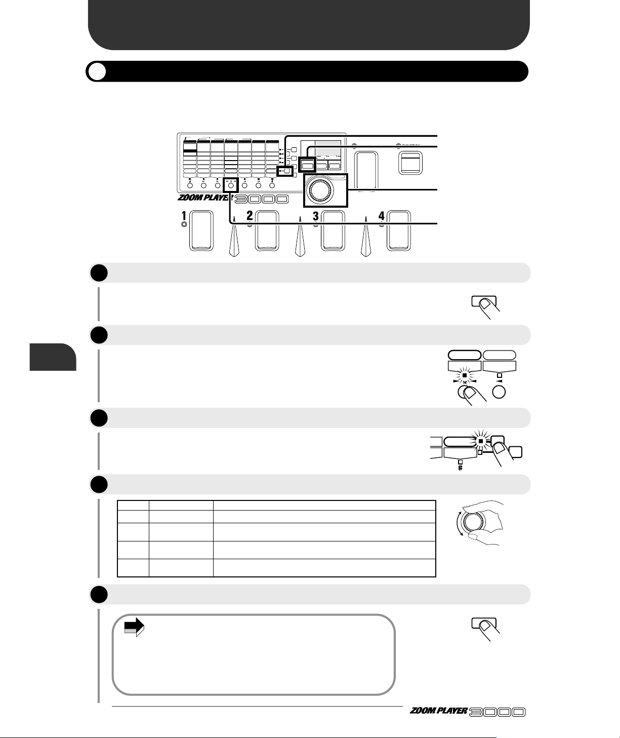
The EFFECT1 module LED flashes.
This is a global parameter that serves for turning the amp simulator on
or off and to select the mode.
• Amp Sim Mode is a global parameter whose setting does not
change when a different patch is selected. It can also be set
when the EFFECT1 module is off.
• If not stored, the setting reverts to the previous value when the
unit is turned off and then on again. When wishing to store the
setting, select any patch in the USER group and store it as
described on page 17.
The 3000 incorporates an amp simulator that can be used for all patches. The amp simulator will produce
realistic guitar amp sound also when monitoring with headphones or over an audio system.
● 28
Other Functions
Other Functions
Using the Amp Simulator
ADVANCED GUITAR EFFECTS PROCESSOR
BANK
FUNCTION
VALUE
ADVANCED GUITAR EFFECTS PROCESSOR
1.COMP
2.BOOSTER
3.OVERDRIVE
4.TALKING BOX
Sens/Gain
(Talking Gain)
Attack/Tone
(Talking Mode)
Level
(MIC Level)
VOLUME RTM
PRE DRIVE RTM
Gain/Top
Tone/Body
Level
ZNR
POSITION
MAIN DRIVE RTM
High/Depth
Midf/Rate/Sens
MidG/Reso
Low/Stage/Inv
Level
EQ RTM
Pitch/Key
Tone/Scale/Time
Shift/Mode/Dly
Bal/Mix
Amp Sim Mode
EFFECT1 RTM
Pitch/Key/Depth
Fine/Scale/Rate
Shift/Mode
Bal/Mix/Peak
SERI/PARA
EFFECT2 RTM
Time(x100mS)
Time(x1mS)
Feedback
Mix
SEAMLESS
DELAY RTM
Time
Tone/FB
Mix
Patch Level
FUNCTION Mode
REVERB RTM
1.OD
3.DIST
5.GRU
7.
METAL
1.3-BAND EQ
2.PHASE
3.PEDAL-WAH
4.AUTO-WAH
1.PITCH
3.DETUNE
4.PEDAL-PITCH
5.STRING
2.HPS 1.HALL1
3.ROOM 1
4.ROOM 2
5.PP-DELAY
2.HALL21.PITCH
3.CHO
5.TREM/PAN
6.RING MOD
1.NORMAL
2.ANALOG
3.HOLD
2.HPS
4.FLG
2.B-OD
4.FUZZ
6.LEAD
8.ACO
PRE DRIVE MAIN DRIVE EQ EFFECT 1 EFFECT 2 DELAY REVERB
TALKING BOX
POSITION SERI/PARA SEAMLESS
FUNCTION MODE BANK(VALUE
)
EDIT(CANCEL)GROUP STORE
1.MANUAL
2.BANK DOWN
3.DELAY(
TAP&HOLD)
4.BYPASS
5.MUTE
6.RTM
7.VOLUME
PRESETUSER
(BOTH) SEAMLESS
U
P
U O
1, 5
4
2
3
Press the EDIT key to activate the Edit mode.
Use the Module Select keys to select the EFFECT1 module.
Use the Parameter Select keys to select "Amp Sim Mode".
Use the VALUE knob to select the amp simulator mode as follows.
Press the EDIT key to revert to Play mode.
EDIT(CANCEL
)
EDIT(CANCEL
)
VALUE
Amp Sim Mode
EFFECT1 RTM
SS
TM
FUNCTION Mode
REVERB RTM
Values Control Assignment
oF OFF Amp simulator function is off.
C1– C9
COMBO
The amp simulator creates a sound resembling that of a combo amplifier of
about 100 watts. Higher values result in stronger box sound.
b1– b9
BRIGHT COMBO
The amp simulator creates a sound resembling that of a bright combo
amplifier of about 120 watts. Higher values result in stronger box sound.
S1– S9 STACK
The amp simulator creates a sound resembling that of a four-speaker
amplifier stack. Higher values result in stronger box sound.
NOTE
STEP
STEP
STEP
STEP
1
2
3
4
STEP
5
Page 31
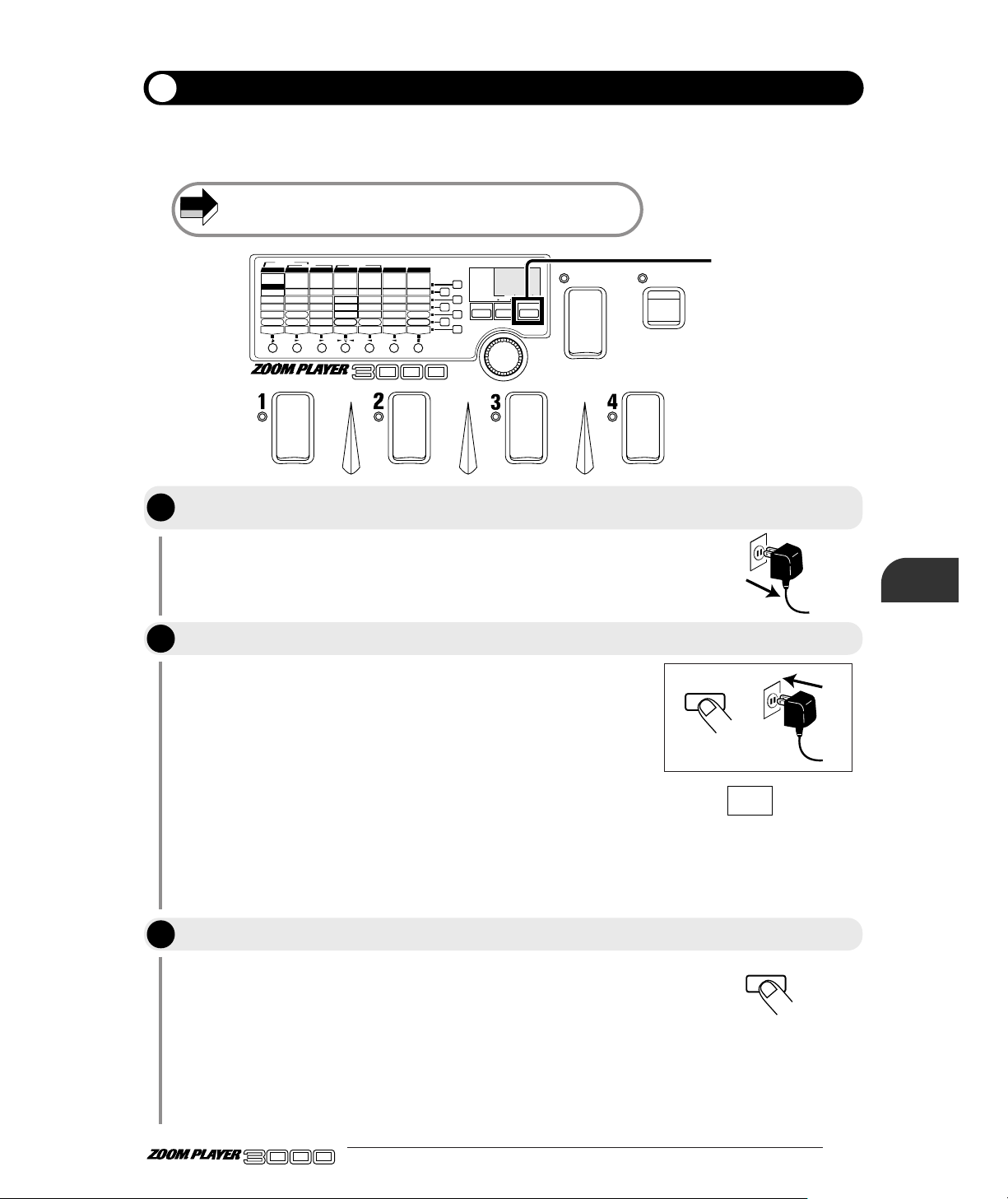
All Initialize is a special function for returning all the patches in the USER group and the values of the
global parameters to their factory settings. Factory Recall allows selective return of a specified patch to
the factory default.
Keep in mind that any patches you have stored will be erased if you
implement the All Initialize function.
29 ●
The indication "AL" appears on the display and the module LED and
parameter LED are flashing. This indicates that the unit is ready for the
All Initialize function.
• To perform All Initialize:
→Proceed to step 3.
• To perform factory Recall:
→Use the BANK switch and Foot Switches 1 - 4 to select the patch
from the USER group which you want to return to the default
condition.
* When wishing to terminate the procedure, press the EDIT key. (The
unit reverts to Play mode.)
When All Initialize is being carried out, the module LED and parameter
LED are flashing quickly. When initialization is completed, the unit
automatically reverts to Play mode.
When Factory Recall is being carried out, the module LED and
parameter LED are flashing quickly and the specified patch is restored.
The unit then remains in standby mode for more patches. When
wishing to terminate Factory Recall, press the EDIT key to return to
Play mode.
BANK
FUNCTION
VALUE
ADVANCED GUITAR EFFECTS PROCESSOR
1.COMP
2.BOOSTER
3.OVERDRIVE
4.TALKING BOX
Sens/Gain
(Talking Gain)
Attack/Tone
(Talking Mode)
Level
(MIC Level)
VOLUME RTM
PRE DRIVE RTM
Gain/Top
Tone/Body
Level
ZNR
POSITION
MAIN DRIVE RTM
High/Depth
Midf/Rate/Sens
MidG/Reso
Low/Stage/Inv
Level
EQ RTM
Pitch/Key
Tone/Scale/Time
Shift/Mode/Dly
Bal/Mix
Amp Sim Mode
EFFECT1 RTM
Pitch/Key/Depth
Fine/Scale/Rate
Shift/Mode
Bal/Mix/Peak
SERI/PARA
EFFECT2 RTM
Time(x100mS)
Time(x1mS)
Feedback
Mix
SEAMLESS
DELAY RTM
Time
Tone/FB
Mix
Patch Level
FUNCTION Mode
REVERB RTM
1.OD
3.DIST
5.GRU
7.
METAL
1.3-BAND EQ
2.PHASE
3.PEDAL-WAH
4.AUTO-WAH
1.PITCH
3.DETUNE
4.PEDAL-PITCH
5.STRING
2.HPS 1.HALL1
3.ROOM 1
4.ROOM 2
5.PP-DELAY
2.HALL21.PITCH
3.CHO
5.TREM/PAN
6.RING MOD
1.NORMAL
2.ANALOG
3.HOLD
2.HPS
4.FLG
2.B-OD
4.FUZZ
6.LEAD
8.ACO
PRE DRIVE MAIN DRIVE E Q EFFECT 1 EFFECT 2 DELAY REVERB
TALKING BOX
POSITION SERI/PARA SEAMLESS
FUNCTION MODE BANK(VALUE
)
EDIT(CANCEL)GROUP STORE
1.MANUAL
2.BANK DOWN
3.DELAY(
TAP&HOLD)
4.BYPASS
5.MUTE
6.RTM
7.VOLUME
PRESETUSER
(BOTH) SEAMLESS
U
P
U O
2, 3
STORE
STORE
A L
Returning the 3000 to the Factory Default Settings (All Initialize/Factory Recall)
Cut the power supply to the 3000. ( Be sure to turn the amplifier volume down to
minimum.)
While holding the STORE key down, reinsert the AC adapter to power up the 3000.
Press the STORE key once more.
ADVANCED GUITAR EFFECTS PROCESSOR
Other Functions
NOTE
STEP
STEP
1
2
STEP
3
Page 32

The TALKING BOX effect is an effect type included in the PRE DRIVE effect module. It changes the
sound of a guitar into sound resembling a human voice. The optional headset microphone HM01 or
another dynamic microphone can be used to change the guitar sound according to your own voice input.
This section explains how to use the microphone to control the TALKING BOX effect.
● 30
Using the Talking Box Effect
Using the Talking Box Effect
Connecting the Microphone
ADVANCED GUITAR EFFECTS PROCESSOR
300mA
DC9V OUTPUT
(PHONES)
MIC IN INPUT
REMOTE IN
SERIAL NO.
MIC IN
Wearing the HM01
HM01
Using the Microphone to Control the Talking Box Effect
To check the effect type, use the Edit mode. For details, please refer to
page 14.
BANK
FUNCTION
VALUE
ADVANCED GUITAR EFFECTS PROCESSOR
1.COMP
2.BOOSTER
3.OVERDRIVE
4.TALKING BOX
Sens/Gain
(Talking Gain)
Attack/Tone
(Talking Mode)
Level
(MIC Level)
VOLUME RTM
PRE DRIVE RTM
Gain/Top
Tone/Body
Level
ZNR
POSITION
MAIN DRIVE RTM
High/Depth
Midf/Rate/Sens
MidG/Reso
Low/Stage/Inv
Level
EQ RTM
Pitch/Key
Tone/Scale/Time
Shift/Mode/Dly
Bal/Mix
Amp Sim Mode
EFFECT1 RTM
Pitch/Key/Depth
Fine/Scale/Rate
Shift/Mode
Bal/Mix/Peak
SERI/PARA
EFFECT2 RTM
Time(x100mS)
Time(x1mS)
Feedback
Mix
SEAMLESS
DELAY RTM
Time
Tone/FB
Mix
Patch Level
FUNCTION Mode
REVERB RTM
1.OD
3.DIST
5.GRU
7.
METAL
1.3-BAND EQ
2.PHASE
3.PEDAL-WAH
4.AUTO-WAH
1.PITCH
3.DETUNE
4.PEDAL-PITCH
5.STRING
2.HPS 1.HALL1
3.ROOM 1
4.ROOM 2
5.PP-DELAY
2.HALL21.PITCH
3.CHO
5.TREM/PAN
6.RING MOD
1.NORMAL
2.ANALOG
3.HOLD
2.HPS
4.FLG
2.B-OD
4.FUZZ
6.LEAD
8.ACO
PRE DRIVE MAIN DRIVE EQ EFFECT 1 EFFECT 2 DELAY REVERB
TALKING BOX
POSITION SERI/PARA SEAMLESS
FUNCTION MODE BANK(VALUE
)
EDIT(CANCEL)GROUP STORE
1.MANUAL
2.BANK DOWN
3.DELAY(
TAP&HOLD)
4.BYPASS
5.MUTE
6.RTM
7.VOLUME
PRESETUSER
(BOTH) SEAMLESS
U
P
U O
5
4
4
3
Verify that the microphone is properly connected to the MIC IN jack on the 3000.
Select a patch which uses the TALKING BOX effect of the PRE DRIVE module.
EDIT(CANCEL
)
Press the EDIT key to enter Edit mode
STEP
STEP
STEP
1
2
3
Page 33

31 ●
This parameter controls the input level from the MIC IN jack. Talk into
the microphone while playing your instrument to find the optimum
position.
You may also try to adjust the Talking Gain (distortion amount)
and Talking Mode (effect variation) parameters.
For information on how to store the parameter settings, please refer to
page 17.
The guitar sound changes according to the mic input.
The TALKING BOX effect can be used also without a microphone.
When the TALKING BOX effect type is selected for the PRE DRIVE
effect module, the MAIN DRIVE effect module cannot be used.
NOTE
HINTHINT
HINTHINT
STEP
In Edit mode, press the PRE DRIVE module key and the parameter 5 key to call
up the MIC Level parameter.
Use the VALUE knob to adjust the MIC Level parameter.
To return to the Play mode, press the EDIT key.
Play your instrument while talking into the microphone.
ADVANCED GUITAR EFFECTS PROCESSOR
Using the Talking Box Effect
EDIT(CANCEL
)
VALUE
PRE DRIVE RTM MAIN DRIVE RTM
Patch Level
FUNCTION Mode
REVERB RTM
4
STEP
STEP
STEP
5
6
7
Page 34

The optional remote pedal RP01 allows use of its foot switch in place of the FUNCTION switch on the
3000. The RP01 has two modes, which serve for different functions.
• RTM mode
The remote pedal RP01 serves for continuously varying the RTM control target for a patch or the
VOLUME RTM. This allows use for pedal wah or the pedal pitch shifter. It is also possible to use the
FUNCTION switch on the 3000 for volume control and the RP01 for RTM control.
• DELAY mode
This mode allows use of the switch on the RP01 for delay time tap input and hold delay operation. It is
also possible to use the FUNCTION switch on the 3000 for RTM and the RP01 for tap input.
(1) Control pedal (with integrated switch)
Serves to control the RTM target parameter or VOLUME RTM etc. By depressing the pedal fully in
RTM mode, pedal wah or pedal pitch shifter can be turned on or off with an integrated switch.
(2) Foot switch
Can be used for on/off switching of pedal wah or pedal pitch shifter, and for delay time tap input and
other functions.
(3) STATUS LED
Shows the operation status of the RP01.
(4) Effect Monitor LEDs
Indicate the on/off condition of the pedal wah and pedal pitch shifter functions.
(5) VOLUME ASSIGN LED
Indicates the on/off condition of the VOLUME RTM function (When lit, the RP01 can be used to
control the volume.)
(6) RTM MODE LED
Lights up when the RP01 is in RTM mode.
(7) DELAY MODE LED
Shows the on/off state of the DELAY module of the 3000 when the RP01 is in DELAY mode.
(8) Mode Selector
Serves to switch between RTM mode and DELAY mode.
● 32
Using the Remote Pedal
Using the Remote Pedal
RP01 Names of Parts / Connections
ADVANCED GUITAR EFFECTS PROCESSOR
PEDAL SW
MODE
SELECT
MONITOR
STATUS
MODE DELECT
PEDAL-WAH ON/OFF(PEDAL SW)
DELAY MODE
(PEDAL SW TRIGGER)
RTM MODE
VOLUME ASSIGN
PEDAL-PITCH ON/OFF(PEDAL SW)
PEDAL SW
MODE
SELECT
MONITOR
STATUS
MODE SELECT
PEDAL-WAH ON/OFF(PEDAL SW)
DELAY MODE
(PEDAL SW TRIGGER)
RTM MODE
VOLUME ASSIGN
PEDAL-PITCH ON/OFF(PEDAL SW)
300mA
DC9V OUTPUT
(PHONES)
MIC IN INPUT
REMOTE IN
SERIAL NO.
(2) Foot switch
(3) STATUS LED
(4) Effect Monitor LEDs
(5) VOLUME ASSIGN LED
(6) RTM MODE LED
(7) DELAY MODE LED
(8) Mode Selector
(1) Control pedal
(with integrated switch)
REMOTE OUT
REMOTE IN
Page 35

33 ●
This section describes how to use the RP01 for controlling the RTM parameter set for the patch.
Before connecting the RP01, make sure that the 3000 is turned off.
Connecting the pedal while the 3000 is on can lead to malfunction.
For details, please refer to the section "Using the FUNCTION switch"
on page 18.
If the FUNCTION switch is set to mode 6 or 7, the function of the
RP01 will be different. Please refer to page 34.
For information on making settings for the RTM function, please refer to
page 23.
Whenever a new patch is called up, the RP01 will be in RTM mode.
● As opposed to using the FUNCTION switch on the 3000, the
Control pedal allows continuous variation of the RTM control
target parameter in both directions, and the value can also be
fixed to a desired point.
NOTE
NOTE
NOTE
MODE SELECT
DELAY MODE
(PEDAL SW TRIGGER)
RTM MODE
RP01 RP01
RTM parameter is positive
RTM parameter is negative
Reference value
Value of
effect parameter
set by RTM
Reference value
Value of
effect parameter
set by RTM
Using the RP01 for Controlling the RTM Target Parameter (RTM Mode)
Verify that the RP01 is properly connected to the 3000.
Set the FUNCTION switch to one of modes 1 - 5.
Call up a patch for which RTM has been set.
Operate the Control pedal of the RP01 while playing your instrument.
ADVANCED GUITAR EFFECTS PROCESSOR
Using the Remote Pedal
RTM LED of RP01 lights up
STEP
STEP
STEP
1
2
3
STEP
4
Page 36
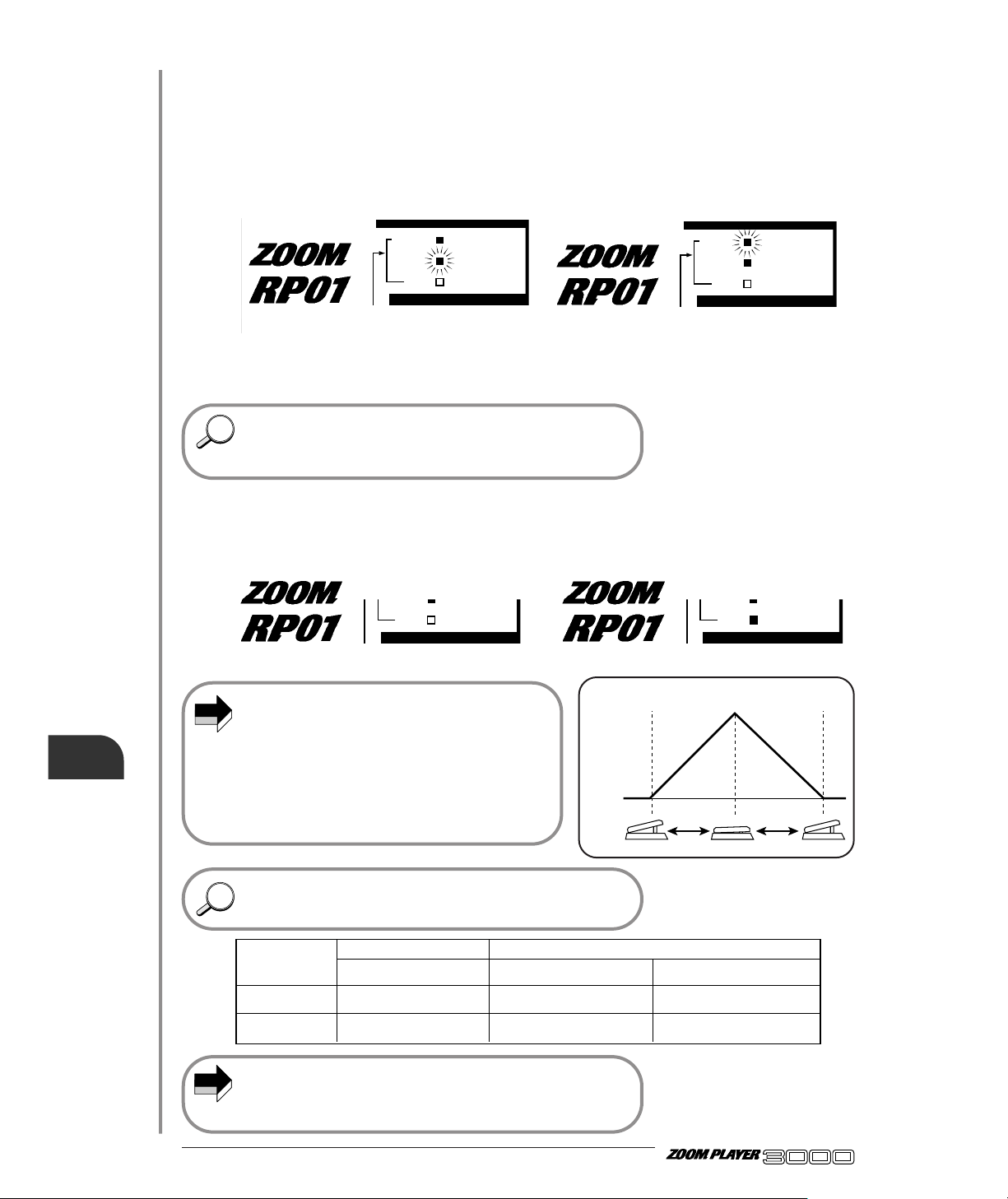
● 34
ADVANCED GUITAR EFFECTS PROCESSOR
● When PEDAL-WAH (EQ module) or PEDAL-PITCH (EFFECT1
module) is selected as effect type for the current patch, the
Control pedal of the RP01 can also be used for pedal wah or the
pedal pitch shifter.
The on/off status for pedal wah or pedal pitch shifter can be verified
with the Effect Monitor LED.
● To switch pedal wah or pedal pitch shifter on or off, use the
switch integrated in the Control pedal or the separate foot switch.
The switch integrated in the Control pedal will be suitable when
wishing to operate the pedal continuously. The separate foot switch
is useful for switching the function on or off while the pedal is only
partially depressed.
● If the VOLUME RTM setting is on for the called patch, the Control
pedal can be used to control the VOLUME RTM action.
In this case, the VOLUME Assign LED lights up.
• If the Effect Monitor LEDs are out, this means
that the effect type PEDAL-WAH or PEDALPITCH is not selected for the current module. In
this case, operating the switch integrated in the
Control pedal or the separate foot switch has no
effect.
• Changes to the RTM parameter are temporary.
When a new patch is called up, the settings for
that patch become active.
When the FUNCTION switch mode is set to 6 or 7, the FUNCTION
switch and the control pedal RP01 can be assigned to different
functions.
When the FUNCTION switch mode of the 3000 is set to 6 (RTM),
the foot switch of the RP01 (or the switch integrated in the Control
pedal) cannot be used to switch pedal wah or pedal pitch shifter on
and off.
NOTE
HINTHINT
HINTHINT
NOTE
MONITOR
MODE SELECT
PEDAL-WAH ON/OFF(PEDAL SW)
RTM MODE
VOLUME ASSIGN
PEDAL-PITCH ON/OFF(PEDAL SW)
pedal pitch shifter :ON(lit)
pedal wah : OFF(flash)
MONITOR
MODE SELECT
PEDAL-WAH ON/OFF(PEDAL SW)
RTM MODE
VOLUME ASSIGN
PEDAL-PITCH ON/OFF(PEDAL SW)
pedal pitch shifter : OFF(flash)
pedal wah :ON(lit)
MODE SELECT
PEDAL-WAH ON/OFF(PEDAL SW)
VOLUME ASSIGN
PEDAL-PITCH ON/OFF(PEDAL SW)
VOLUME RTM: off (LED out)
MODE SELECT
PEDAL-WAH ON/OFF(PEDAL SW)
VOLUME ASSIGN
PEDAL-PITCH ON/OFF(PEDAL SW)
VOLUME RTM: on (LED lit)
RP01
Volume RTM on
VOLUME
No sound
Using the Remote Pedal
FUNCTION switch
mode
6: RTM mode
7: VOLUME mode
RP01 not connected
FUNCTION switch operation
RTM including VOLUME RTM
(3000)
(VOLUME RTM setting valid)
Overall output level of 3000
FUNCTION switch operation
(VOLUME RTM setting is invalid)
(3000)
RTM except VOLUME RTM
(VOLUME RTM setting invalid)
Overall VOLUME RTM
RP01 connected
Control pedal operation
(RP01)
Overall VOLUME RTM
(VOLUME RTM setting is invalid)
RTM except VOLUME RTM
(VOLUME RTM setting invalid)
Page 37

35 ●
This section describes how to use the RP01 for operating the DELAY mode.
Before connecting the RP01, make sure that the 3000 is turned off.
Connecting the pedal while the 3000 is on can lead to malfunction.
• When the selected patch uses the NORMAL or ANALOG effect type,
tap input of delay time is possible.
• When the selected patch uses the HOLD effect type, hold delay
operation is possible.
DELAY MODE LED lights up when the DELAY module of the 3000 is on
and flashes when it is off.
• Operation is the same as when using the FUNCTION switch on the
3000. The STATUS LED serves as function LED. For details, please
refer to "Setting Delay Time With Foot Switch" on page 21 or "Using
Hold Delay" on page 22.
• When the RP01 is connected and DELAY mode is selected, delay
time tap input or hold delay operation cannot be carried out
with the FUNCTION switch on the 3000, also if the FUNCTION
switch mode is set to "3: DELAY (TAP&HOLD)".
* When the RP01 is in DELAY mode, the Control pedal can be
used to adjust the balance between delay sound and original
sound. The integrated switch can be used to turn delay on and
off.
NOTE
NOTE
MODE SELECT
MODE DELECT
DELAY MODE
(PEDAL SW TRIGGER)
RTM MODE
DELAY MODE LED lights when
DELAY module of 3000 is on.
Push the Mode Selector
Push the Mode Selector
Verify that the RP01 is properly connected to the 3000.
Select a patch for which the DELAY effect module is on.
Push the Mode Selector of the RP01 to select DELAY mode.
To return to the RTM mode, press the Mode Selector once more.
Use the foot switch on the RP01 to perform tap input of the delay time, or perform
hold delay operation.
ADVANCED GUITAR EFFECTS PROCESSOR
Using the Remote Pedal
Using the RP01 for Delay Tap Input or Hold Delay Operation (DELAY Mode)
STEP
STEP
STEP
STEP
1
2
3
4
STEP
5
Page 38

● 36
ADVANCED GUITAR EFFECTS PROCESSOR
This section explains all the Zoom Player 3000's effect types and parameters. However, parameters that
are the same for other effect types are only explained in brief.
• Parameters marked with "G" are global parameters, and parameters marked with "P" are
patch parameters. These parameters can be changed regardless of the on/off condition
of the respective effect module.
• Parameters marked with "←RTM" are parameters which can be operated by RTM when
that effect module is selected.
Depending on the type selected for the effect module, some parameters have no setting item ( shaded section in the
illustration). For information on the display of such parameters, please refer to page 14.
This module comprises distortion effects such as compressor and overdrive. The talking box effect for
use with a microphone and the VOLUME RTM setting are also part of this module.
■ Parameter 1 TYPE (Effect Type)
The following four effect types can be selected for
the PRE DRIVE effect module.
Type 1 COMP (Compressor)
Type 2 BOOSTER
Type 3 OVERDRIVE
Type 4 TALKING BOX
Depending on the selected effect type, the content of
parameters 2, 3, 5, 7 changes.
■ Type 1 COMP (Compressor)
This effect keeps the level constant, resulting in a
steady and stable sound.
●Parameter 2 Sens (←RTM)
Determines the depth of the compression effect.
●Parameter 3 Attack
Determines the time interval between guitar attack
sound and the start of compression.
■ Type 2 BOOSTER
Booster effect with emphasis on mid and upper
range.
●Parameter 2 Gain (←RTM)
Determines the distortion intensity.
●Parameter 3 Tone
Adjusts the high-frequency range sound.
■ Type 3 OVERDRIVE
Overdrive effect giving the kind of distortion
produced by a tube amplifier. The parameters are the
same as for BOOSTER of type 2.
Parameter 1
TYPE
1. COMP 2. BOOSTER 3. OVERDRIVE 4. TALKING BOX
Parameter 2
Sens(←RTM) Gain(←RTM) TalkingGain(←RTM)
1〜10 1〜16 1〜16
Parameter 3
Attack Tone TalkingMode
0〜10 0〜10 M1,M2,G1,G2
Parameter 4
Level
1〜30
Parameter 5
MICLevel
1〜10
Parameter 6
VOLUMERTM(P)
oF,on
Parameter 7
PREDRIVERTM
oF,dn,UP
PREDRIVERTM
−10〜+10
PRE DRIVE
Effect Types and Parameters
Effect Types and Parameters
NOTE
Page 39

■ Parameter 1 TYPE (Effect Type)
The following eight effect types can be selected for
the MAIN DRIVE effect module.
Type 1 OD (Overdrive)
Type 2 B-OD (Blues Overdrive)
Type 3 DIST (Distortion)
Type 4 FUZZ
Type 5 GRU (Grunge)
Type 6 LEAD
Type 7 METAL
Type 8 ACO (Acoustic)
Depending on the selected effect type, the content of
parameters 2, 3, 4 and 7 changes.
37 ●
Parameter 1
TYPE
1. OD 2. B-OD 3. DIST 4. FUZZ 5. GRU 6. LEAD 7. METAL 8. ACO
Parameter 2
Gain(←RTM)
Top
1〜30 1〜10
Parameter 3
Tone Body
0〜10 1〜10
Parameter 4
Level
1〜30
Level(←RTM)
1〜30
Parameter 5
ZNR(P)
oF,1〜7
Parameter 6
POSITION(P)
ME,EM,Pr
Parameter 7
MAINDRIVERTM
oF,dn,UP
MAINDRIVERTM
−10〜+10
MAIN DRIVE
ADVANCED GUITAR EFFECTS PROCESSOR
Effect Types and Parameters
■ Type 4 TALKING BOX
When this effect type is selected and you speak into
a microphone connected to the MIC IN jack, the
signal from the microphone influences the sound of
the guitar you are playing. Even if no microphone is
connected, this effect yields an interesting sound.
When this effect type is selected, the MAIN DRIVE
effect module cannot be used.
●Parameter 2 Talking Gain (←RTM)
Determines the amount of distortion.
●Parameter 3 Talking Mode
Selects an effect variation.
The M1 and M2 variation can be controlled with the
optional headset microphone HM01 or another
dynamic microphone.
M1 : Mild sound (with microphone input)
M2 : Wide-range effect (with microphone input)
G1 : Mild sound (with guitar input)
G2 : Wide-range effect (with guitar input)
●Parameter 5 MIC Level
M1, M2: Determines the MIC IN jack input level.
G1, G2 : Determines the guitar jack input
sensitivity.
■ Common parameters for type 1 - 4
●Parameter 4 Level
Determines the module output level.
●Parameter 6 VOLUME RTM (P)
This patch parameter determines whether the patch
volume is controlled in RTM. When set to on, the
FUNCTION switch or optional remote pedal RP01
can be used to control the input level to the
EFFECT1 or EFFECT2 module. For details, please
refer to page 23 and 33.
●Parameter 7 PRE DRIVE RTM
Determines the change direction and control range
for the parameter marked with "¨RTM". When set to
a positive value, the value of the control target
parameter increases when the FUNCTION switch or
remote pedal RP01 is operated. When set to a
negative value, the value decreases. The current
setting of the control target parameter is used as a
reference point, and the range extends from -10 (100%) to +10 (+100%). For distortion effect types,
this becomes the setting value of "oF", "UP, and
"dn". For details, please refer to the note on page 25.
This module contains mainly distortion type effects. It also comprises the ZNR settings (patch
parameter) and the connection type settings for the MAIN DRIVE and EQ modules (patch parameter).
Page 40

● 38
ADVANCED GUITAR EFFECTS PROCESSOR
■ Type 1 OD (Overdrive)
Tube-amp type overdrive distortion. This is a
variation of the PRE DRIVE overdrive distortion.
●Parameter 2 Gain (←RTM)
Determines the amount of distortion.
●Parameter 3 Tone
Adjusts the tonal quality. Higher values result in
brighter sound.
■ Type 2 B-OD (Blues Overdrive)
Solid overdrive best suited for blues numbers. The
parameter content is the same as for type 1 (OD).
■ Type 3 DIST (Distortion)
Large amplifier type distortion. The parameter
content is the same as for type 1 (OD).
■ Type 4 FUZZ
Vintage fuzz essential for the rock style of the
sixties. The parameter content is the same as for type
1 (OD).
■ Type 5 GRU
Modern fuzz with a stimulating sound. The
parameter content is the same as for type 1 (OD).
■ Type 6 LEAD
Clear, distinct sound optimally suited for lead guitar.
The parameter content is the same as for type 1
(OD).
■ Type 7 METAL
Heavy metal type sound with a prominent treble and
bass. The parameter content is the same as for type 1
(OD).
■ Type 8 ACO (Acoustic)
Acoustic guitar simulator which changes the sound
of an electric guitar into an acoustic type sound.
●Parameter 2 Top
Adjusts the high-frequency range. Higher values
stress the characteristic string sound of an acoustic
guitar.
●Parameter 3 Body
Adjusts the low-frequency range. Higher values
result in a more pronounced body sound.
■ Common parameters for type 1 - 8
●Parameter 4 Level (←RTM)
Determines the module output level.
●Parameter 5 ZNR (P)
This patch parameter controls the sensitivity of the
ZNR (Zoom Noise Reduction) circuit. The
recommended approach is to set the value as high as
possible without producing an unnatural cut of the
instrument sound. When set to "oF", ZNR is
disabled.
●Parameter 6 POSITION (P)
This patch parameter determines the connection
method of the MAIN DRIVE module and EQ
module. "ME" (MAIN DRIVE → EQ),
"EM" (EQ →MAIN DRIVE), and "Pr" (parallel) can
be selected.
When the TALKING BOX effect of the PRE DRIVE
module is selected, the signal is directly sent to the
EQ module. The POSITION parameter can therefore
not be set. (Refer to the illustration at the bottom of
page 4.)
●Parameter 7 MAIN DRIVE RTM
Determines the change direction and control range
for the parameter marked with "←RTM".
NOTE
Effect Types and Parameters
"ME" setting
MAIN DRIVE EQ
"EM" setting
"Pr setting
EQ MAIN DRIVE
MAIN DRIVE
EQ
Page 41

■ Parameter 1 TYPE (Effect Type)
The following four effect types can be selected for
the EQ effect module.
Type 1 3-BAND EQ
Type 2 PHASE (Phaser)
Type 3 PEDAL-WAH
Type 4 AUTO-WAH
Depending on the selected effect type, the content of
parameters 2 - 7 changes.
■ Type 1 3-BAND EQ
This 3-band equalizer allows adjusting the highfrequency range, mid-frequency range, and lowfrequency range.
●Parameter 2 High
Controls boost/cut for the high-frequency range.
●Parameter 3 Midf
The midrange frequency can be selected from the
following values: 0.2 (250 Hz), 0.4 (400 Hz), 0.8
(800 Hz), 1.2 (1.25 kHz), 2.0 (2 kHz), 3.1 (3.15
kHz), 5.6 (5.6 kHz), 8.0 (8 kHz).
●Parameter 4 MidG
Determines boost/cut for the mid-frequency range.
●Parameter 5 Low
Controls boost/cut for the low-frequency range.
●Parameter 6 Level (←RTM))
Determines the module output level.
A setting of "25" yields flat response.
●Parameter 7 EQ RTM
Determines the change direction and control range
for the parameter marked with "←RTM".
■ Type 2 PHASE (Phaser)
Adds a phase-shifted effect component to the direct
sound, creating a special undulating sound.
●Parameter 2 Depth
Determines the depth of the phaser effect.
●Parameter 3 Rate (←RTM)
Determines the speed of the phaser effect.
●Parameter 4 Reso
Determines the resonance component of the phaser
effect.
●Parameter 5 Stage
Determines the number of stages for the phaser
effect. When set to "8", a detailed phaser effect is
achieved.
●Parameter 6 Level
●Parameter 7 EQ RTM
■ Type 3 PEDAL-WAH
This effect type allows use of the optional remote
pedal RP01 or the FUNCTION switch of the 3000
for pedal wah.
●Parameter 2 High
Controls boost/cut for the high-frequency range.
●Parameter 3 f
Determines the initial frequency (when pedal is not
operated).
●Parameter 5 Low
Controls boost/cut for the low-frequency range.
●Parameter 6 Level
●Parameter 7 EQ RTM
Determines the direction in which the wah effect
changes when the pedal is pressed. "dn" means a
downward change and "UP" an upward change.
39 ●
ADVANCED GUITAR EFFECTS PROCESSOR
Parameter 1
TYPE
1. 3-BAND EQ 2. PHASE 3. PEDAL-WAH 4. AUTO-WAH
Parameter 2
High Depth High Depth
−12〜+12 0〜10 −12〜+12 1〜10
Parameter 3
Midf Rate(←RTM) f Sens(←RTM)
0.2/0.4/0.8/1.2/2.0/3.1/5.6/8.0 1〜50 1〜50 1〜10
Parameter 4
MidG Reso Reso
−12〜+12 0〜10 1〜3
Parameter 5
Low Stage Low Inv
−12〜+12 4,8 −12〜+12 dn,UP
Parameter 6
Leve(←RTM) Level
1〜30 1〜30
Parameter 7
EQRTM EQRTM EQRTM
−10〜+10 oF,dn,UP −10〜+10
EQ
Effect Types and Parameters
This effect module comprises a 3-band equalizer, phaser, and wah effects.
Page 42
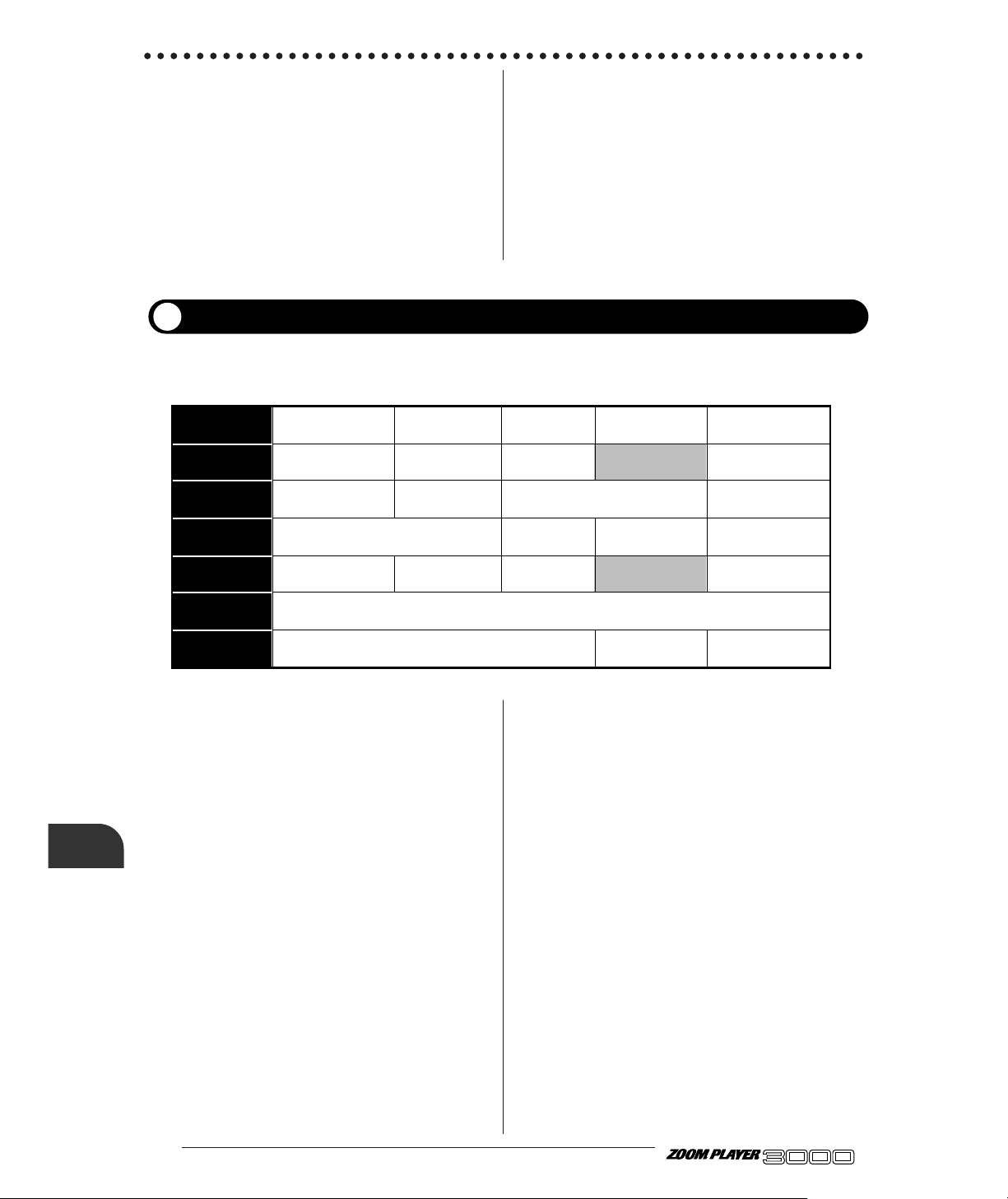
● 40
ADVANCED GUITAR EFFECTS PROCESSOR
■ Parameter 1 TYPE (Effect Type)
The following five effect types can be selected for
the EFFECT1 effect module.
Type 1 PITCH (Pitch Shifter)
Type 2 HPS (Harmonized Pitch Shifter)
Type 3 DETUNE
Type 4 PEDAL-PITCH (Pedal Pitch Shifter)
Type 5 STRING (Strings)
Depending on the selected effect type, the content of
parameters 2 - 5 and 7 changes.
■ Type 1 PITCH (Pitch Shifter)
Allows to shift the pitch over a range of 2 octaves up
or down.
●Parameter 2 Pitch
Determines the amount of pitch shift in semitones.
●Parameter 3 Tone
Adjusts the high-frequency range of the effect.
Lower values result in a softer sound with less treble.
●Parameter 4 Shift
Determines the direction of pitch shift. "dn" means a
downward change and "UP" an upward change.
●Parameter 5 Bal (←RTM)
Determines the level balance between effect sound
and original sound. "0" means original sound only,
and "1.0" (100) means effect sound only.
●Parameter 7 EFFECT1 RTM
Determines the change direction and control range
for the parameter marked with "←RTM".
■ Type 2 HPS (Harmonized Pitch Shifter)
Pitch shifter which creates harmonies using a preset
key and scale.
●Parameter 2 Key
Determines the main key for the scale (C, C#, d, d#,
E, F, F#, g, g#, A, A#, b).
●Parameter 3 Scale
Determines the scale of the harmony.
M3 = Major 3rd, m3 = minor 3rd, 4t = 4th, 5t = 5th,
6t = 6th
Effect Types and Parameters
This module contains mainly pitch shift type effects. The amp simulator (global parameter) settings are
also part of this module.
Parameter 1
TYPE
1. PITCH 2. HPS 3. DETUNE 4. PEDAL-PITCH 5. STRING
Parameter 2
Pitch Key Pitch Pitch
0,1,2,・・・11,12,24 C,C#,・・・A#,b −12〜+12 0,1,2,・・・11,12,24
Parameter 3
Tone Scale Tone Time
0〜10 M3,m3,4t,5t,6t 0〜10 0〜99
Parameter 4
Shift Dly Mode Shift
dn,UP 0〜50 1〜8 dn,UP
Parameter 5
Bal(←RTM) Mix(←RTM) Bal(←RTM) Bal(←RTM)
0〜99,1.0 0〜99,1.0 0〜99,1.0 0〜99,1.0
Parameter 6
AmpSimMode(G)
oF,C1〜C9,b1〜b9,S1〜S9
Parameter 7
EFFECT1RTM EFFECT1RTM EFFECT1RTM
−10〜+10 dn,UP −10〜+10
EFFECT1
■ Type 4 AUTO-WAH
This effect type creates an automatic wah effect that
depends on the picking intensity.
●Parameter 2 Depth
Determines the depth of the auto-wah effect.
●Parameter 3 Sens (←RTM)
Determines the sensitivity of the auto-wah effect.
●Parameter 4 Reso
Adds a special touch to the auto-wah effect.
●Parameter 5 Inv
Determines the direction of change for the auto-wah
effect. "dn" means a downward change and "UP" an
upward change of the emphasized frequency.
●Parameter 6 Level
●Parameter 7 EQ RTM
Determines the change direction and control range
for the parameter marked with "←RTM".
Page 43

41 ●
ADVANCED GUITAR EFFECTS PROCESSOR
Effect Types and Parameters
●Parameter 4 Shift
●Parameter 5 Mix (←RTM)
Determines the mixing balance between effect sound
and original sound.
●Parameter 7 EFFECT1 RTM
When using this effect type, you should play single
notes.
■ Type 3 DETUNE
This effect type uses a creative mix of pitch-shifted
effect sound and original sound to achieve a chorus
sound with only slight modulation.
●Parameter 2 Pitch
Determines the pitch detune amount.
●Parameter 3 Tone
Adjusts the high-frequency range of the effect.
Higher values result in a softer sound with less
treble.
●Parameter 4 Dly
Determines the delay time of the effect.
●Parameter 5 Bal (←RTM)
Determines the level balance between effect sound
and original sound. "0" means original sound only,
and "1.0" (100) means effect sound only.
●Parameter 7 EFFECT1 RTM
■ Type 4 PEDAL-PITCH (Pedal Pitch Shifter)
This effect type is designed for use with the optional
remote pedal RP01 or the FUNCTION switch of the
3000.
●Parameter 3 Tone
●Parameter 4 Mode
The following eight modes can be selected for the
pitch shift method.
●Parameter 7 EFFECT1 RTM
When a patch is called or the effect type is switched
and the pedal pitch shifter is selected, the pedal up
condition corresponds to the default value.
■ Type 5 STRING (Strings)
This effect type combines a pitch shifter and slow
attack for automatic "violin playing" sound.
●Parameter 2 Pitch
Determines the amount of pitch shift in semitones.
●Parameter 3 Time
Determines the time until the onset of the effect.
●Parameter 4 Shift
Determines the direction of pitch shift. "dn" means a
downward change and "UP" an upward change.
●Parameter 5 Bal (←RTM)
Determines the level balance between pitch shifted
sound with delayed attack and original sound.
●Parameter 7 EFFECT1 RTM
Determines the change direction and control range
for the parameter marked with "←RTM".
■ Common parameters for type 1 - 5
●Parameter 6 Amp Sim Mode (G)
This is a global parameter which determines the
sound character of the amp simulator. For details,
please refer to "Using the Amp Simulator" on page
28.
NOTE
When
RTM parameter
is "UP"
Pedal down
Pedal down
Pedal up
When
RTM parameter
is "dn"
Mode
1: Dirty Bend
2: Detune
3: Bend Up
4: Arm Down
5: Octave Harmony
6: -5th/+4th
7: Cross-Fade
8: Stop
-100 cent
DOUBLING
0 cent
0 cent
-1 oct + DRY
-700 cent + DRY
-<infinite> + DRY
-<infinite> + DRY
DRY
-30 cent + DRY
+1 oct
-2 oct
+1 oct + DRY
+500 cent + DRY
+1 oct
+1 oct + DRY
Pedal up
Page 44

● 42
ADVANCED GUITAR EFFECTS PROCESSOR
■
Parameter 1 TYPE (Effect Type)
The following six effect types can be selected for the
EFFECT2 module.
Type 1 PITCH (Pitch Shifter)
Type 2 HPS (Harmonized Pitch Shifter)
Type 3 CHO (Chorus)
Type 4 FLG (Flanger)
Type 5 TREM/PAN (Tremolo/Auto Panpot)
Type 6 RING MOD (Ring Modulator)
Depending on the selected effect type, the content of
parameters 2 - 5 changes.
■ Type 1 PITCH (Pitch Shifter)
Allows to shift the pitch over a range of 2 octaves up
or down.
●Parameter 2 Pitch
Determines the amount of pitch shift in semitones.
●Parameter 3 Fine
Allows fine-adjusting of pitch shift amount.
●Parameter 4 Shift
Determines the direction of pitch shift. "dn" means a
downward change and "UP" an upward change.
●Parameter 5 Bal (←RTM)
Determines the level balance between effect sound
and original sound. "0" means original sound only,
and "1.0" (100) means effect sound only.
■ Type 2 HPS (Harmonized Pitch Shifter)
Pitch shifter which creates harmonies using a preset
key and scale. By using this effect together with the
HPS of the EFFECT1 module, a three-part harmony
can be created. The parameter content is the same as
for HPS in the EFFECT1 module.
When using this effect type, you should play single
notes.
■ Type 3 CHO (Chorus)
This is a chorus effect which achieves an expansive,
warm sound.
●Parameter 2 Depth
Determines the depth of the effect.
●Parameter 3 Rate
Determines the modulation rate.
●Parameter 4 Mode
Determines the chorus effect variation.
M1,M2 = mono chorus variation
S1,S2 = stereo chorus variation
●Parameter 5 Mix (←RTM)
■ Type 4 FLG (Flanger)
This is a flanger effect which creates a surging jet
sound.
●Parameter 2 Depth
●Parameter 3 Rate (←RTM)
Determines the rate of the flanger effect.
●Parameter 4 Mode (PreDLY)
Determines the delay time of the flanger effect.
●Parameter 5 Peak (FB)
Adjusts the wave characteristic of the flanger effect.
NOTE
Effect Types and Parameters
Parameter 1
TYPE
1. PITCH 2. HPS 3. CHO 4. FLG 5. TREM/PAN 6. RING MOD
Parameter 2
Pitch Key Depth
0,1,2,・・・11,12,24 C,C#,・・・A#,b
0〜10
Depth(Time)
0〜10
Parameter 3
Fine Scale Rate Rate(←RTM)
−10〜oF〜+10
M3,m3,4t,5t,6t
1〜50 1〜50
Parameter 4
Shift Mode Mode Mode(DEPTH) Mode(Reso)
dn,UP
M1,M2,S1,S2
1〜10 0〜10 0〜10
Parameter 5
Bal(←RTM) Mix(←RTM) Peak(FB) Peak(CLIP) Mix
0〜99,1.0 0〜99,1.0 0〜10 0〜10 0〜99,1.0
Parameter 6
SERI/PARA(P)
Sr,P1〜P9
Parameter 7
EFFECT2RTM
−10〜+10
EFFECT2
This effect module comprises modulation effects such as chorus, flanger, tremolo, etc. The connection
method of the EFFECT1 module and EFFECT2 module (serial or parallel) is also determined in this
module.
Page 45

43 ●
ADVANCED GUITAR EFFECTS PROCESSOR
Effect Types and Parameters
■ Type 5 TREM/PAN (Tremolo/Auto Panpot)
This effect type combines a tremolo effect with an
automatic panpot that shifts the sound between left
and right.
●Parameter 2 Depth
Determines the depth of the tremolo effect.
●Parameter 3 Rate (←RTM)
Determines the rate of the tremolo effect.
●Parameter 4 Mode (DEPTH)
Determines the depth of the auto panpot.
●Parameter 5 Peak (CLIP)
Varies the modulation waveform. Higher values
result in stronger clipping of the waveform, which
emphasizes the tremolo effect.
■ Type 6 RING MOD (Ring Modulator)
This is a ring modulator which produces a metallic
sound.
●Parameter 2 Depth (Time)
Determines the delay time of the effect sound.
●Parameter 3 Rate (←RTM)
Determines the modulation frequency.
●Parameter 4 Mode (Reso)
Determines the resonance of the ring modulator.
●Parameter 5 Mix
Determines the level balance between effect sound
and original sound. "0" means original sound only,
and "1.0" (100) means effect sound only.
■ Common parameters for type 1 - 6
●Parameter 6 SERI/PARA (P)
This patch parameter determines the connection
method of the EFFECT1 and EFFECT2 modules.
The following settings are available.
• Sr: EFFECT1 and EFFECT2 are connected in series.
• P1 - P9: EFFECT1 and EFFECT2 are connected in
parallel. The value at right adjusts the level balance of
EFFECT1 and EFFECT2 (P1 results in a high level for
EFFECT1 and P9 in a high level for EFFECT2.
●Parameter 7 EFFECT2 RTM
Determines the change direction and control range
for the parameter marked with "←RTM".
Parameter 1
TYPE
1. NORMAL 2. ANALOG 3. HOLD
Parameter 2
Time(x100mS)
0〜20
Parameter 3
Time(x1mS)
0〜99
Parameter 4
Feedback
0〜10
Parameter 5
Mix(←RTM)
0〜99,1.0
Parameter 6
SEAMLESS
oF,1〜10,∞
Parameter 7
DELAYRTM
−10〜+10
This effect module contains mainly delay effects. When wishing to use the FUNCTION switch or
optional remote pedal RP01 for the hold delay function, set the effect type for this effect module to
"HOLD".
DELAY
■ Parameter 1 TYPE (Effect Type)
The following three effect types can be selected for
the DELAY effect.
Type 1 NORMAL (Normal Delay)
Type 2 ANALOG (Analog Delay)
Type 3 HOLD (Hold Delay)
Depending on the selected effect type, the content of
parameter 4 changes.
"P1"
EFFECT 1 EFFECT 2
EFFECT 1
EFFECT 2
"P1"
EFFECT 1
EFFECT 2
"Sr" setting
"P1" – "P9" setting
Page 46
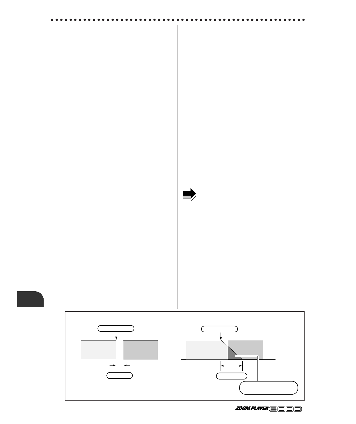
■ Type 1 NORMAL (Normal Delay)
Conventional delay effect with a maximum delay
time of 2 seconds.
●Parameter 2 Time (x100 ms)
Determines the delay time in 100-ms units.
●Parameter 3 Time (x1 ms)
Determines the delay time in 1-ms units.
●Parameter 4 Feedback
Determines the delay feedback amount.
●Parameter 5 Mix (←RTM)
Determines the mixing balance between effect sound
and original sound. "0" means original sound only,
and "1.0" (100) means equal level of effect sound
and original sound.
■ Type 2 ANALOG (Analog Delay)
Analog type delay with a soft sound character. The
parameter content is the same as for type 1
(NORMAL).
■ Type 3 HOLD (Hold Delay)
This effect type samples a phrase of up two seconds
and repeats it automatically.
●Parameter 2 Time (x100 ms)
Determines the hold delay time (maximum sampling
time) in 100-ms units.
●Parameter 3 Time (x1 ms)
Determines the hold delay time in 1-ms units.
●Parameter 5 Mix (←RTM)
Determines the mixing balance between effect sound
and original sound.
■ Common parameters for type 1 - 3
●Parameter 6 SEAMLESS
This parameter controls the seamless function. For
details, please refer to the explanation of the
seamless function below.
●Parameter 7 DELAY RTM Mode
Determines the change direction and control range
for the parameter marked with "←RTM".
■ Seamless function
The seamless function lets the delay sound from the
previous patch linger on when you switch patches,
creating a smooth transition without audible breaks.
The following settings can be made for seamless
function:
• oF: Seamless function is off.
• 1 - 10: Delay sound continues for the number of
seconds set with this value, regardless of the Feedback
parameter setting of the DELAY effect.
• infinite: Delay sound continues for the duration of
the Feedback parameter setting of the DELAY effect.
• If the delay time for the patch before switching or
after switching exceeds 1 second (1001 ms or
more), the seamless function becomes inactive.
• Also if the DELAY module is set to off for the
patch after switching, a delay time setting of 1001
ms or more will cause the seamless function to
become inactive when the DELAY module is set to
off. Set the delay time to 1000 ms or less and turn
the DELAY module off.
• When hold delay is used for a patch for which the
seamless function value has been set to 1 - 10, the
sampled phrase is repeated for the specified
duration only. If the seamless function is set to
<infinite> and patch hold delay is used, the
repetition of the sampled phrase continues also
when the patch is switched (until bypass/mute is
activated).
● 44
ADVANCED GUITAR EFFECTS PROCESSOR
Effect Types and Parameters
NOTE
Conventional patch switching
Patch is switched
PATCH 1 PATCH 2
Sound is cut
Seamless function
Patch is switched
PATCH 1 PATCH 2
PATCH 1 delay
The delay sound of PATCH 1
overlaps the sound of PATCH 2
Page 47
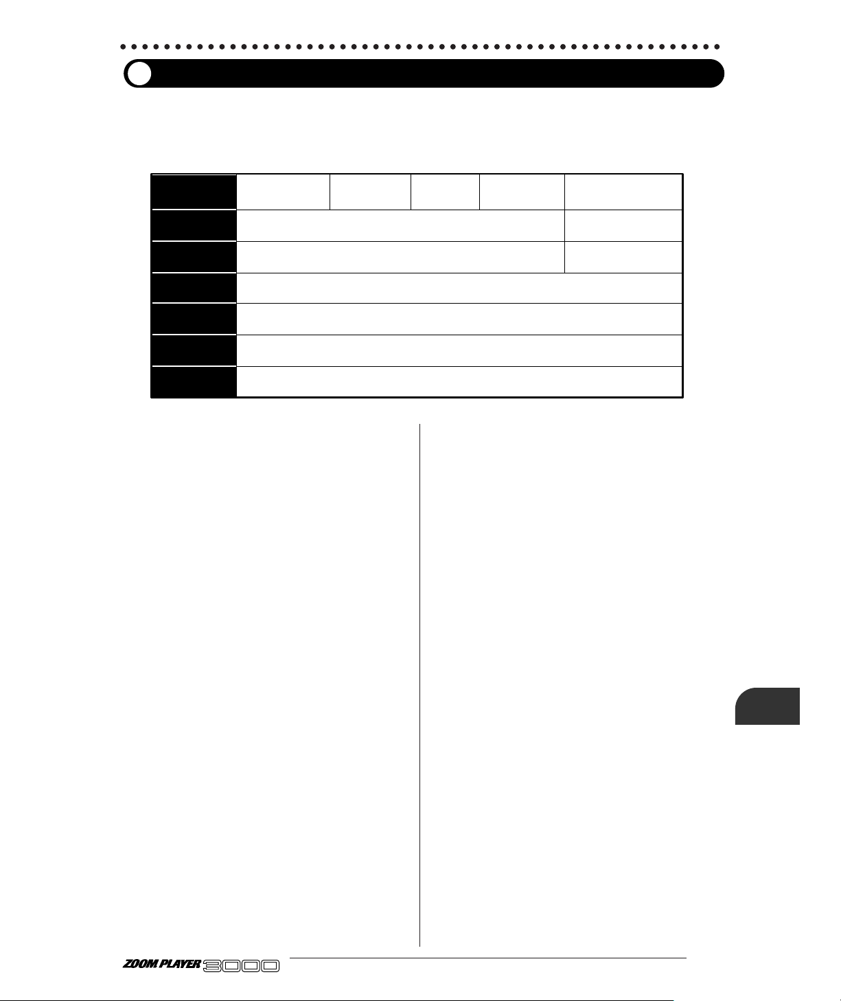
45 ●
ADVANCED GUITAR EFFECTS PROCESSOR
Effect Types and Parameters
REVERB
This effect module contains reverberation effects. It also comprises the Patch Level parameter for
adjusting the overall patch level, and the FUNCTION Mode parameter for selecting the FUNCTION
switch operation.
Parameter 1
TYPE
1. HALL 1 2. HALL 2 3. ROOM 1 4. ROOM 2 5. PP-DELAY
Parameter 2
Time Time(x10mS)
1〜30 1〜99,1.0
Parameter 3
Tone FB
0〜10 0〜10
Parameter 4
Mix(←RTM)
0〜99,1.0
Parameter 5
PatchLevel(P)
1〜50
Parameter 6
FUNCTIONMode(G)
1〜7
Parameter 7
REVERBRTM
−10〜+10
■ Parameter 1 TYPE (Effect Type)
The following five effect types can be selected for
the REVERB effect module:
Type 1 HALL1 (Hall Reverb 1)
Type 2 HALL2 (Hall Reverb 2)
Type 3 ROOM1 (Room Reverb 1)
Type 4 ROOM2 (Room Reverb 2)
Type 5 PP-DELAY (Ping-Pong Delay)
Depending on the selected effect type, the content of
parameters 2 - 3 changes.
■ Type 1 HALL1 (Hall Reverb 1)
Bright reverb effect simulating the sound of a
concert hall.
●Parameter 2 Time
Determines the duration of the reverb.
●Parameter 3 Tone
Adjusts the high-frequency range of the effect.
Lower values result in a softer sound with less treble.
■ Type 2 HALL2 (Hall Reverb 2)
Warm reverb effect simulating the sound of a concert
hall. The parameter content is the same as for type 1
(HALL1).
■ Type 3 ROOM1 (Room Reverb 1)
Bright reverb effect simulating the sound of a room.
The parameter content is the same as for type 1
(HALL1).
■ Type 4 ROOM2 (Room Reverb 2)
Warm reverb effect simulating the sound of a room.
The parameter content is the same as for type 1
(HALL1).
■ Type 5 PP-DELAY (Ping-Pong Delay)
Ping-pong effect which bounces the effect sound
between left and right.
●Parameter 2 Time (x10 ms)
Determines the delay time in 10-ms units.
●Parameter 3 FB
Determines the delay feedback amount.
■ Common parameters for type 1 - 5
●Parameter 4 Mix (←RTM)
Determines the mixing balance between effect sound
and original sound.
●Parameter 5 Patch Level (P)
This patch parameter sets the overall level of the
patch.
●Parameter 6 FUNCTION Mode (G)
This global parameter determines the operation of
the FUNCTION switch. For information about the
various modes, please refer to page 18.
●Parameter 7 REVERB RTM
Determines the change direction and control range
for the parameter marked with "←RTM".
Page 48

● 46
ADVANCED GUITAR EFFECTS PROCESSOR
Troubleshooting
Problem
Check Remedy
No Sound, or
Extremely Small
Sound
• Is the AC adapter connected correctly
and the power ON?
Turn the power ON by following the
instructions, "GETTING CONNECTED".
• Is the INPUT jack correctly connected to the
guitar, and the OUTPUT jack to the amplifier?
Connect them correctly by following the
instructions , "GETTING CONNECTED".
• Is your shielded cable ok?
Try changing your shielded cable.
• Is the connected amplifier's power ON?
Turn the amplifier's power ON.
• Is the volume appropriate for the guitar
and amplifier?
Adjust the volume to the appropriate level.
• LEVEL parameter of PRE DRIVE, MAIN
DRIVE, or EQ effect module set too low?
Activate Edit mode (page 13 and adjust the
parameter.
Turn VALUE knob in Play mode to adjust
the volume.
Operate RP01 foot pedal.
• Is the cut with the EQ effect module
parameter setting too strong?
Enter the Edit mode (see page13 ) and
appropriately adjust the levels for each
parameter.
• Master volume turned down?
• Volume turned down with RP01 (option)
foot pedal?
• Is the 3000 muted?
If the FUNCTION switch mode (see page 18)
is set to "MUTE", press the FUNCTION
switch to turn off the mute condition.
Patches Do Not
Switch
• Is the 3000 in Edit (Manual) mode?
Press FUNCTION switch to return to Play
mode.
• Is the 3000 in Store standby status or
All Initialize standby status?
Press the STORE key to execute the
operation, or press the EDIT key to leave the
standby status and return to Play mode.
FUNCTION
switch cannot
be used for
delay time tap
input or hold
delay.
• FUNCTION switch mode set correctly?
Set FUNCTION switch mode to "3: DELAY
(TAP&HOLD)" (page 18).
• Is RP01 (option) connected?
When RP01 is connected, delay time tap
input and hold delay operation can be
carried out only with RP01.
MAIN DRIVE
effect module
cannot be
activated.
• Is TALKING BOX effect type selected for
PRE DRIVE effect module?
In Edit mode, select a different effect type for
PRE DRIVE. If TALKING BOX is selected,
the MAIN DRIVE effect module cannot be
activated even if the PRE DRIVE module is
off.
Troubleshooting
If there seems to be a problem with the unit, please check the following points first.
Page 49

47 ●
ADVANCED GUITAR EFFECTS PROCESSOR
Troubleshooting
Problem
Check Remedy
RP01 foot pedal
cannot be used
for RTM
(including pedal
wah and pedal
pitch shifter).
• Is a patch with RTM selected?
Activate Edit mode and make the RTM
settings (page 23).
• Is effect type with pedal wah or pedal pitch
shifter selected?
Verify that the PEDAL-WAH or PEDALPITCH effect type is selected for EQ or
EFFECT1 (page 37, 38).
• Is Effect Monitor LED off (flashing)?
Press pedal switch so that LED becomes on
(lit).
• Is RP01 set to DELAY mode?
Press Mode Selector of RP01 to switch to
RTM mode.
• Is FUNCTION switch of 3000 set to
"6: RTM"?
When FUNCTION switch is set to "6:
RTM", RP01 foot pedal works as volume
pedal. Set FUNCTION switch to other mode
(page 32).
Pedal wah or
pedal pitch
shifter does not
turn on or off
when
integrated
switch of RP01
pedal is
pressed.
• Is RP01 set to DELAY mode?
Press Mode Selector of RP01 to switch to
RTM mode.
• Is 3000 FUNCTION switch mode set to
"6: RTM"?
When mode 6 (RTM) is activated, integrated
switch of RP01 pedal cannot be used to
switch pedal wah or pedal pitch shifter on
and off (page 32). Select another mode.
Talking box
effect cannot
be used with
microphone.
• Is microphone properly connected to MIC
IN jack?
Connect microphone as described on page
30.
• Is TALKING BOX selected as effect
type for PRE DRIVE module?
In Edit mode, verify that TALKING BOX is
selected as effect type for PRE DRIVE
module.
• Is MIC Level parameter of PRE DRIVE
effect module set to a suitable value?
In Edit mode, try increasing the MIC Level
parameter.
Page 50

● 48
ADVANCED GUITAR EFFECTS PROCESSOR
Effect programs 37(35 effect types + Amp Simulator + ZNR)
Effect modules 7 + AMP + ZNR
Patch memory capacity USER 10 banks x 4 = 40 (read and write)
PRESET 10 banks x 4 = 40 (read only)
Total 80 patches
Sampling frequency 39.0625 kHz
A/D converter 20 bit, 64 times oversampling
D/A converter 20 bit, 128 times oversampling
DSP ZFx-2 (developed by ZOOM) x 2
Input Guitar input (standard monaural phone jack)
Rated input level: -20 dBm
Input impedance: 470 kilohms
Microphone input (standard monaural phone jack)
Rated input level: -50 dBm
Input impedance: 470 kilohms
Output Combined line/headphone output
(standard monaural phone jack)
Max. output level: +6 dBm
Output load impedance: 10 kilohms or more
Control connector For optional RP01
Display 2-digit , 7-segment LED
Power requirements 9 VDC, 300 mA (from supplied AC adapter)
Dimensions 373 (W) x 200 (D) x 46 (H) mm
Weight 1.5 kg
* 0 dBm = 0.775 Vrms
* Design and specifications subject to change without notice.
SPECIFICATIONS
SPECIFICATIONS
Page 51
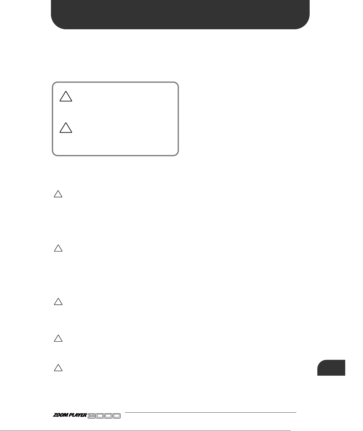
49 ●
ADVANCED GUITAR EFFECTS PROCESSOR
USAGE AND SAFETY PRECAUTIONS
USAGE AND SAFETY
PRECAUTIONS
USAGE AND SAFETY PRECAUTIONS
In this manual, symbols are used to highlight
warnings and cautions for you to read so that
accidents can be prevented. The meanings of these
symbols are as follows:
Please observe the following safety tips and precautions to ensure
hazard-free use of the 3000.
• Power requirements
The 3000 is powered by the supplied AC adapter. To
prevent malfunction and safety hazards, do not use any
other kind of AC adapter.
When using the 3000 in an area with a different line
voltage, please consult your local ZOOM distributor about
acquiring a proper AC adapter.
• Environment
Avoid using your 3000 in environments where it will be
exposed to:
• Extreme temperature
• High humidity or moisture
• Excessive dust or sand
• Excessive vibration or shock
• Handling
Since the 3000 is a precision electronic device, avoid
applying excessive force to the switches and buttons. Also
take care not to drop the unit, and do not subject it to shock
or excessive pressure.
• Alterations
Never open the case of the 3000 or attempt to modify the
product in any way since this can result in damage to the
unit.
• Connecting cables and input and output
jacks
You should always turn off the power to the 3000 and all
other equipment before connecting or disconnecting any
cables. Also make sure to disconnect all cables and the AC
adapter before moving the 3000.
Usage Precautions
• Electrical interference
For safety considerations, the 3000 has been designed to provide
maximum protection against the emission of electromagnetic
radiation from inside the device, and protection from external
interference. However, equipment that is very susceptible to
interference or that emits powerful electromagnetic waves should
not be placed near the 3000, as the possibility of interference
cannot be ruled out entirely.
With any type of digital control device, the 3000 included,
electromagnetic interference can cause malfunctioning and can
corrupt or destroy data. Care should be taken to minimize the risk
of damage.
• Cleaning
Use a soft, dry cloth to clean the 3000. If necessary, slightly
moisten the cloth. Do not use abrasive cleanser, wax, or solvents
(such as paint thinner or cleaning alcohol), since these may dull
the finish or damage the surface.
Please keep this manual in a convenient place for future
reference.
!
!
Warning
This symbol indicates explanations about
extremely dangerous matters. If users ignore
this symbol and handle the device the wrong
way, serious injury or death could result.
Caution
This symbol indicates explanations about
dangerous matters. If users ignore this symbol
and handle the device the wrong way, bodily
injury and damage to the equipment could
result.
!
Warning
!
Caution
!
Caution
!
Caution
!
Caution
Page 52

ZOOM CORPORATION
NOAH Bldg., 2-10-2, Miyanishi-cho, Fuchu-shi, Tokyo 183-0022, Japan
PHONE: 0423-69-7116 FAX: 0423-69-7115
Printed in Japan 3000-5000
 Loading...