

Page 1

ZGP323ICE02ZEMG
Z8 GP™ ZGP323 In-Circuit Emulator
User Manual
UM019606-0408
Copyright ©2008 by Zilog®, Inc. All rights reserved.
www.zilog.com
Page 2

Revision History
Each instance in the Revision History table reflects a change to this document from its previous revision. For more details, refer to the corresponding pages and appropriate links in the following table.
Z8 GP™ ZGP323 In-Circuit Emulator
User Manual
ii
Revision
Date
April 2008 06 Replaced
Level Description
Figure 5 and
Figure 11.
February
2008
05 Updated Connecting ZGP323
ICE to the Target Pod
and Z8 GP
Package Support and Ordering
Information
December
2007
September
2007
04 Updated System Requirements,
Debugger instructions, trace/
event procedure, and
03 Updated
Figure 12, and Burn Code from
the Current Project
July 2007 02 Updated document with latest
company address and
implemented Zilog Style Guide.
November
2005
01 Original Issue All
.
Figure 12
System Requirements,
.
Page
Number
8 and 16
5 and 34
2
, 23, 20,
and
24.
2, 20, and
25
All
UM019606-0408 Revision History
Page 3

Table of Contents
Introduction . . . . . . . . . . . . . . . . . . . . . . . . . . . . . . . . . . . . . . . . . . . . . 1
Kit Features . . . . . . . . . . . . . . . . . . . . . . . . . . . . . . . . . . . . . . . . . . . 1
System Requirements . . . . . . . . . . . . . . . . . . . . . . . . . . . . . . . . . . . 2
Software Installation . . . . . . . . . . . . . . . . . . . . . . . . . . . . . . . . . . . . . 2
Hardware Installation . . . . . . . . . . . . . . . . . . . . . . . . . . . . . . . . . . . . 3
Connecting Target Pod . . . . . . . . . . . . . . . . . . . . . . . . . . . . . . . 3
Connecting ZGP323 ICE to the Target Pod . . . . . . . . . . . . . . . . 5
Connecting ZGP323 ICE to OTP Programming
Module (Optional) . . . . . . . . . . . . . . . . . . . . . . . . . . . . . . . . . 5
Connecting ZGP323 ICE to a PC . . . . . . . . . . . . . . . . . . . . . . . . 6
Ethernet Port Connection . . . . . . . . . . . . . . . . . . . . . . . . . . . . . . 6
USB Port Connection . . . . . . . . . . . . . . . . . . . . . . . . . . . . . . . . 15
Z8 GP™ ZGP323 In-Circuit Emulator
User Manual
iii
Sample Project . . . . . . . . . . . . . . . . . . . . . . . . . . . . . . . . . . . . . . . . . 18
Collecting a Trace . . . . . . . . . . . . . . . . . . . . . . . . . . . . . . . . . . 21
Using an Event to Stop Execution . . . . . . . . . . . . . . . . . . . . . . 22
Collecting Trace After an Event . . . . . . . . . . . . . . . . . . . . . . . . 24
OTP Programming . . . . . . . . . . . . . . . . . . . . . . . . . . . . . . . . . . 25
Burn Code from the Current Project . . . . . . . . . . . . . . . . . . . . . 25
Burn Code from an Existing Hex File . . . . . . . . . . . . . . . . . . . . 29
LED Indicators . . . . . . . . . . . . . . . . . . . . . . . . . . . . . . . . . . . . . . . . 32
External Interface Connectors . . . . . . . . . . . . . . . . . . . . . . . . . . . . 32
Using J5 Pin 3, External Trigger Out . . . . . . . . . . . . . . . . . . . . 33
Using J5 Pin 1, External Trigger In . . . . . . . . . . . . . . . . . . . . . . 33
Z8 GP Package Support and Ordering Information . . . . . . . . . . . . 34
Appendix A–ZGP323 ICE
Commands. . . . . . . . . . . . . . . . . . . . . . . . . . . . . . . . . . . . . . . . . . . . . 35
Customer Support. . . . . . . . . . . . . . . . . . . . . . . . . . . . . . . . . . . . . . . 37
UM019606-0408 Table of Contents
Page 4

Introduction
Zilog’s Z8 GP™ ZGP323 In-Circuit Emulator (ICE) provides Z8 GP chip
family emulation with a Trace and Event system for program debugging
using Zilog Developer Studio II (ZDS II) development tools. Once your
code is complete, use the included OTP programming module to burn
your design on to OTP devices.
Kit Features
The kit includes the following features:
•
Emulation and OTP Programming support for the Z8 GP Family
•
Emulation Pod for 20- and 28- Pin PDIP Packages
Z8 GP™ ZGP323 In-Circuit Emulator
User Manual
1
•
Z8 GP ZGP323 Evaluation Board
•
Trace and Event System
•
Ethernet and USB Interface
•
Up to 8 MHz Clock Frequency
•
2.0–3.6 V V
•
ZDS II
•
Assembler and Full ANSI C Compiler
•
Documentation
•
Sample OTP Devices
UM019606-0408 Introduction
DD
Page 5

Z8 GP™ ZGP323 In-Circuit Emulator
User Manual
System Requirements
Table 1 lists the system requirements for running ZDS II.
Table 1. ZDS II System Requirements
Recommended Configuration Minimum Configuration
PC running MS Windows XP Pro PC running MS Windows 98 SE/
Windows2000-SP4/Windows XP Pro
Pentium III/500 MHz processor Pentium II/233 MHz processor
128 MB RAM 96 MB RAM
65 MB hard disk space 25 MB hard disk space (documentation not
included)
Super VGA video adapter Super VGA video adapter
CD-ROM drive CD-ROM drive
2
Ethernet port Ethernet or USB port
USB high-speed or full-speed port
One or more RS-232 communications ports
Internet browser (Internet Explorer or Netscape) Internet browser (Internet Explorer or
Note: 1 RS232 communication port is not necessary when using USB or default Ethernet IP
1
Netscape)
Software Installation
Follow the steps below to install ZDS II with ANSI C-Compiler:
1. DemoShield program available in the ZDS II installation CD
launches automatically. Otherwise, go to the root of the CD-ROM and
double-click the file
UM019606-0408 Introduction
launch.exe.
Page 6

2. DemoShield provides several installation options to install ZDS II,
select Install ZDS II. You can install other software and accompanying documentation later.
3. Follow the instructions on the screen to complete the installation.
Hardware Installation
The ZGP323 ICE features an Ethernet interface, a USB interface, and an
RS-232 serial port. Hardware installation consists of the following:
•
Connecting Target Pod
•
Connecting ZGP323 ICE to the Target Pod
•
Connecting ZGP323 ICE to OTP Programming Module (Optional)
•
Connecting ZGP323 ICE to a PC
Z8 GP™ ZGP323 In-Circuit Emulator
User Manual
3
You have to reconfigure network settings on the PC or on the ZGP323
ICE before using the emulator.
Connecting Target Pod
Use an appropriate target pod and pin converter to connect the ZGP323
ICE to the target board. Figure 1 on page 4 illustrates the ZGP323 ICE top
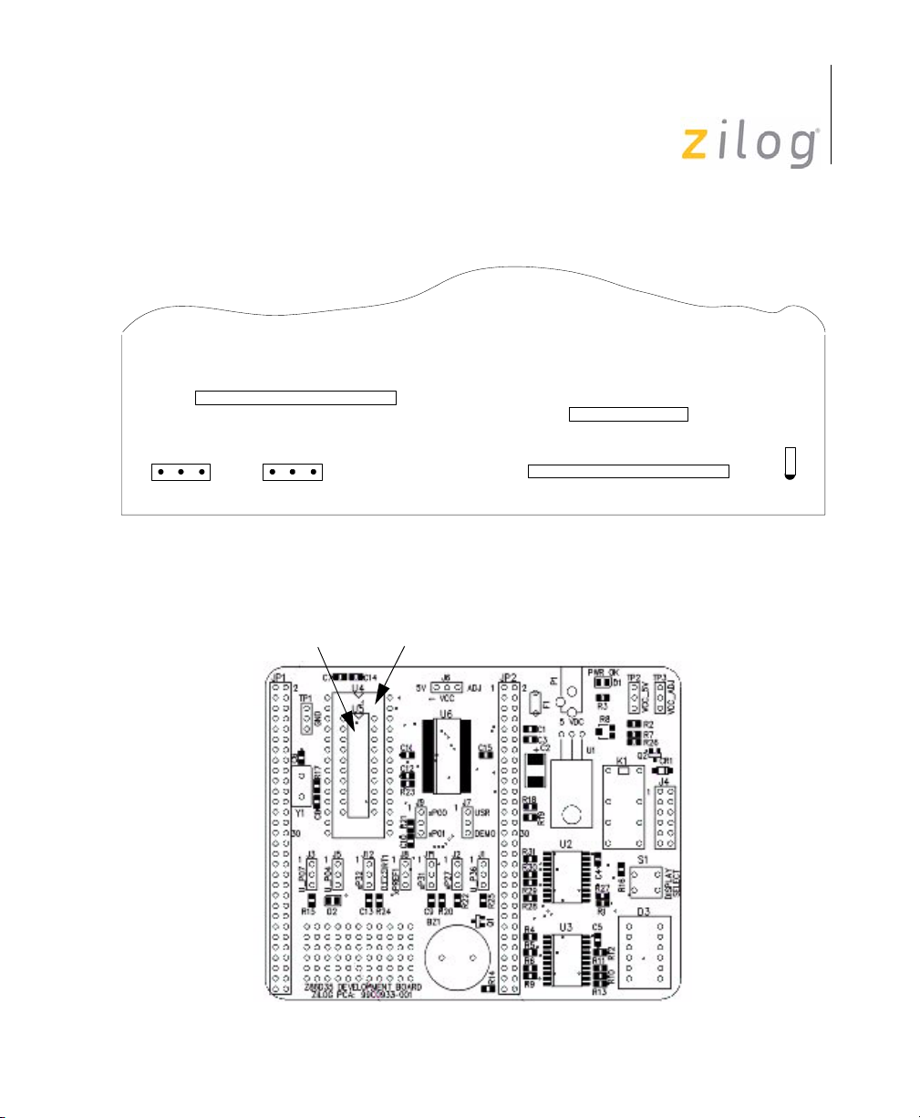
panel connectors and Figure 2 on page 4 illustrates the ZGP323 evaluation board included with the kit. The 20- and 28-PDIP target pods plug
into the associated PDIP sockets on the target board. For example, if your
target board has a 20-SOIC socket, mate the 20-PDIP target Pod onto the
20-PDIP to 20-SOIC converter. Then install the target pod and converter
assembly into the board’s 20-SOIC socket
UM019606-0408 Introduction
Page 7
J5
J9
Out In
Target Trigger
OTP Programming
1
J4
J8
GND
Z8 GP™ ZGP323 In-Circuit Emulator
1
J7
1
Int Target
CLK Source
Figure 1. ZGP323 ICE Top View
P9
P17
Target Interface
P10
P16
Target Interface
User Manual
4
D1
20-PDIP
Socket
28-PDIP
Socket
Figure 2. ZGP323 Evaluation Board
UM019606-0408 Introduction
Page 8

Z8 GP™ ZGP323 In-Circuit Emulator
Connecting ZGP323 ICE to the Target Pod
After installing the appropriate target pod (and converter, if required) onto
the target development board, connect the ZGP323 ICE to the target pod
as follows:
•
For 40-PDIP and 48-SSOP target pods:
– Connect the 20-circuit cable from P9 on the emulator to P2 on
the 40-PDIP target pod. (The 20-circuit cable is included in the
40/48-pin accessory kit, ZLP323ICE01ZAC, ordered separately).
User Manual
5
Note:
ZLP323ICE01ZAC has been replaced by an improved version,
ZCRMZNICE02ZACG.
– Connect the 34-circuit cable from P10 on the emulator to P1 on
the 40-PDIP target pod.
•
For 20-PDIP and 28-PDIP target pods:
– Connect the 34-circuit cable from P10 on the emulator to P16 on
the target pod. (Emulator connector P9 is not used).
Connecting ZGP323 ICE to OTP Programming Module (Optional)
After developing and debugging your software, follow the steps below to
connect the ZGP323 ICE to the OTP programming module so that you
can burn your code onto the OTP chip:
1. Connect the 40-circuit ribbon cable from the ZGP323 ICE OTP Programming connector to connector P1 on the OTP programming module.
2. The 40-PDIP ZIF socket on the OTP programming module is
designed to accept 40-PDIP OTP chips. The OTP programming
adapters supplied with the ZGP323 ICE allow you to adapt the ZIF
UM019606-0408 Introduction
Page 9

Z8 GP™ ZGP323 In-Circuit Emulator
socket to accept 20/28-PDIP chip packages.Other adapters are available separately, see Z8 GP Package Support and Ordering Informa-
tion on page 34 for more information.
After installing the OTP chip into the ZIF socket (or programming
adapter), you can program the chip using the instructions provided in
OTP Programming on page 25.
Connecting ZGP323 ICE to a PC
You can connect the ZGP323 ICE to a host PC using either an Ethernet or
USB port. To connect the ZGP323 ICE to a host PC using Ethernet, see
Ethernet Port Connection. To connect the ZGP323 ICE to a host PC using
USB port, see USB Port Connection on page 15.
Ethernet Port Connection
User Manual
6
Follow the steps below to connect the ZGP323 ICE to a host PC using
Ethernet:
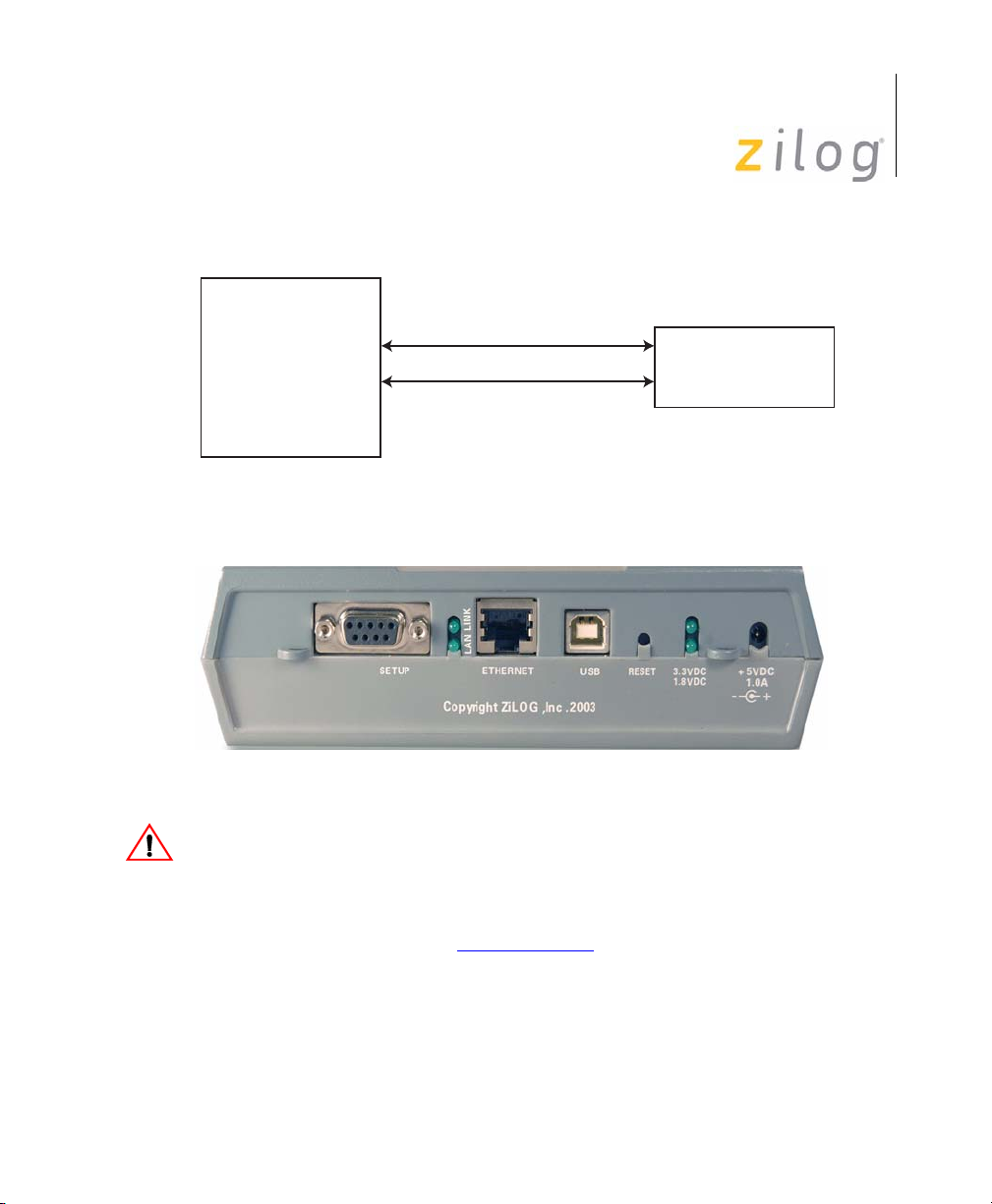
1. Connect a CAT-5 crossover cable from the PC to the Ethernet port on
the ZGP323 ICE, see Figure 3.
Note:
UM019606-0408 Introduction
You can connect the ICE to an Ethernet hub using a CAT-5 patch
cable.
2. Connect the serial COM port on the PC to the SETUP serial port on
the ZGP323 ICE using the DB9-to-DB9 serial cable, see Figure 5 on
page 8.
Page 10
Z8 GP™ ZGP323 In-Circuit Emulator
CAT-5 Crossover Cable
PC
DB9-to-DB9 Cable
Figure 3. Connecting a PC to the ZGP323 ICE
User Manual
7
ZGP323
ICE
Figure 4. ZGP323 ICE Rear Panel
Caution:
Ensure the target board is not powered ON.
3. Connect a 5 V DC power supply to the ZGP323 ICE. The 3.3 V DC
and 1.8 V DC power LEDs must illuminate, see Figure 5. Contact
®
Zilog
UM019606-0408 Introduction
support at www.zilog.com if there is any problem.
Page 11

Z8 GP™ ZGP323 In-Circuit Emulator
User Manual
ICE Fail LED
ICE Run LED
8
Figure 5. ZGP323 ICE Front Panel
Setting Up Ethernet Communications
The default IP address and subnet mask of the ZGP323 ICE are
192.168.1.50 and 255.255.255.0, respectively. To enable communication
between the PC running ZDS II and the ZGP323 ICE, you must either
change the PC’s Ethernet settings to match those of the ZGP323 ICE or
vice versa.
If using the PC in a stand-alone configuration, set the PC’s IP address to
192.168.1.21 and its subnet mask to 255.255.255.0. For more details, see
Changing the PC’s Settings to Match the ZGP323 ICE.
In a networked environment, set the ZGP323 ICE IP address and subnet
mask to match the network setup. For more details, see Changing
ZGP323 ICE Settings on page 13.
UM019606-0408 Introduction
Page 12

Z8 GP™ ZGP323 In-Circuit Emulator
User Manual
Changing the PC’s Settings to Match the ZGP323 ICE
Follow the steps below to change the PC’s Ethernet settings:
9
Note:
The following instructions are for MS Windows XP. If your Windows OS is
different, refer to your MS Windows OS online help for details.
1. Open the Windows Control Panel and double-click the Network
Connections icon, see Figure 6 on page 9.
Figure 6. Network Connections
UM019606-0408 Introduction
Page 13
Z8 GP™ ZGP323 In-Circuit Emulator
User Manual
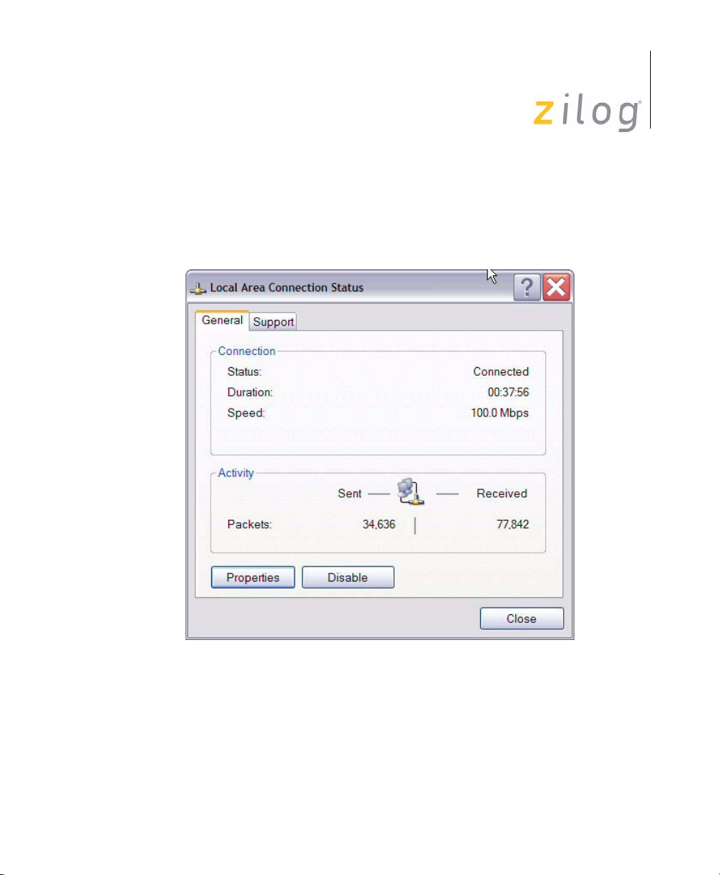
2. In the panel labeled LAN or High-Speed Internet, double-click the
Local Area Connection icon. The Local Area Connection Status
window appears, see Figure 7.
10
Figure 7. Local Area Connection Status Window
UM019606-0408 Introduction
Page 14

Z8 GP™ ZGP323 In-Circuit Emulator
User Manual
3. In the Local Area Connection Status window, click Properties button. The Local Area Connection Properties dialog box appears, see
Figure 8.
11
Figure 8. Local Area Connection Properties Dialog Box
UM019606-0408 Introduction
Page 15

Z8 GP™ ZGP323 In-Circuit Emulator
User Manual
4. Select Internet Protocol (TCP/IP) from the scroll down list, and
click Properties button. The Internet Protocol (TCP/IP) Properties
dialog box appears, see Figure 9.
12
Figure 9. Internet Protocol Properties Dialog
UM019606-0408 Introduction
Page 16

Z8 GP™ ZGP323 In-Circuit Emulator
User Manual
5. Enter the IP address and subnet mask to match those shown in
Figure 9 on page 12. Leave the remaining fields blank. In this exam-
ple, an IP address of 192.168.1.21 and a subnet mask of
255.255.255.0 are being assigned to the PC. These values connect the
PC to the same network as the ZGP323 ICE unit.
6. Click OK and restart the PC.
13
Note:
To execute a sample project, see Sample Project on page 18.
Changing ZGP323 ICE Settings
Follow the steps below to change the ZGP323 ICE Settings:
1. Connect the serial port of the PC to the ZGP323 ICE serial port using
the DB9-to-DB9 serial cable.
2. Launch HyperTerminal on the PC by selecting Start ––> Programs
––> Accessories ––> Communications ––> HyperTerminal. The
Connection Description dialog box appears.
3. Enter the name for a new connection in the Connection Description
dialog box, and click OK to open the Connect To dialog box.
4. In the Connect To dialog, set the Connect Using drop-down menu to
match the COM port to which the ZGP323 ICE is connected. Click
OK.
5. A COM Properties dialog appears. Enter the following port settings
and click OK. HyperTerminal should automatically attempt a connection. Otherwise, select Call ––> Connect.
Bits per second 57600
Data bits 8
Parity None
Stop bits 2
Flow control None
UM019606-0408 Introduction
Page 17

Z8 GP™ ZGP323 In-Circuit Emulator
User Manual
6. When the emulator is turned on or reset, a ZGP323 ICE console bootup message appears in the HyperTerminal. A typical boot-up message
is shown below:
ZiLOG Z8 LXM ICE
Firmware Version 2.0, Build (Aug 22 2005 08:14:37)
Copyright (C) 2005 ZiLOG, Inc. All Rights Reserved.
Adding emac driver...
Attempting to establish Ethernet connection.
10 Mbps Half-Duplex Link established
IP Address: 10.1.7.95
IP Subnet: 10.1.0.0/255.255.0.0
IP Gateway: 10.1.1.254
Press 'Ctrl-Z' to enter configuration mode
7. Press Ctrl-z. The emulator command prompt appears:
Z8 LXM ICE %
14
Note:
The emulator console prompt is not case-sensitive.
Type help or ? at the emulator command prompt to see a list of available
commands. For information on the description of the complete ZGP323
ICE commands, see Appendix A–ZGP323 ICE Commands on page 35.
8. When you have finished configuring the emulator, type
exit to exit
the command shell.
9. Press Alt+F4 to exit HyperTerminal.
10. Type
reboot and press Return or cycle the power on the ZGP323
ICE for the new settings to take effect.
11. The hardware is now configured and ready for application development.
Note:
UM019606-0408 Introduction
To execute a sample project, see Sample Project on page 18.
Page 18

USB Port Connection
To connect the ZGP323 ICE to your PC using a USB port, load the appropriate driver from the ZDS II installation directory or CD-ROM provided
with your emulator. ZDS II software is available for download from
www.zilog.com
on your Windows OS version and is explained below:
Windows XP
Follow the steps below to connect the ZGP323 ICE to a host PC using
USB Connection for Windows XP OS version:
1. Connect the ZGP323 ICE to the host PC using the supplied USB
cable, see Figure 10 for ZGP323 ICE rear panel connection.
. The procedure of loading the appropriate driver, depends
Z8 GP™ ZGP323 In-Circuit Emulator
User Manual
15
Figure 10. ZGP323 ICE Rear Panel
Caution:
Ensure the target board is not powered ON.
2. Connect a 5 V DC power supply to the ZGP323 ICE. The 3.3 V DC
and 1.8 V DC power LEDs should illuminate, see Figure 5 on page 8.
Contact Zilog
®
support at www.zilog.com if there is any problem.
In Windows, the Found New Hardware wizard should activate auto-
matically.
UM019606-0408 Introduction
Page 19

Z8 GP™ ZGP323 In-Circuit Emulator
User Manual
ICE Fail LED
ICE Run LED
16
Figure 11. ZGP323 ICE Front Panel
3. In the wizard, select Install from a list or specific location
(Advanced); click Next.
Note:
If the Windows Logo testing dialog appears, select Continue Anyway.
4. Select Search for the best driver in these locations and include
those locations in the search.
5. Browse to one of the following driver directories:
<ZDS II Installation Directory>\device drivers\USB
<ZDS II Installation CD>\Device Drivers\USB
6. Click Next.
7. Select the appropriate driver, and click Next.
UM019606-0408 Introduction
Page 20

Z8 GP™ ZGP323 In-Circuit Emulator
User Manual
8. Click Finish to complete the installation.
Windows 2000/Windows 98SE
Follow the steps below to connect the ZGP323 ICE to a host PC using
USB Connection for Windows 2000/Windows 98SE OS version:
1. Connect the ZGP323 ICE to the host PC using the supplied USB
cable, see Figure 10 on page 15 for ZGP323 ICE rear panel connection.
17
Caution:
Ensure the target board is not powered ON.
2. Connect a 5 V DC power supply to the ZGP323 ICE. The 3.3 V DC
and 1.8 V DC power LEDs should illuminate, see Figure 5 on page 8.
Contact Zilog
®
support at www.zilog.com if there is any problem.
In Windows, the Found New Hardware wizard must activate automatically.
3. In the wizard, click Next.
4. Select Search for a suitable driver for my device (Recommended);
click Next.
5. Select Specify a location, click Next.
6. Browse to one of the following driver directories:
<ZDS II Installation Directory>\device drivers\USB
<ZDS II Installation CD>\Device Drivers\USB
7. Click Next.
8. Select the appropriate driver, and click Next.
9. Click Finish to complete the installation.
UM019606-0408 Introduction
Page 21

Sample Project
After installing the ZDS II software and setting up the hardware, you are
ready to execute the sample software project to verify proper emulator
operation and to test with the Trace and Event system. This section
describes how to run the emulator in the in-circuit mode.
Z8 GP™ ZGP323 In-Circuit Emulator
User Manual
18
Notes:
Note:
1. If you run the emulator with a target attached, the emulator’s voltage
comparator is designed to serve as a target power sensor, and not as
a precision voltage measurement device. If you set the Target VCC to
match your target and the target’s voltage drifts downward, the power
sensor may no longer detect it. The emulator may therefore not connect to the target. In such cases, set the Target VCC voltage progressively lower until a proper connection is established.
2. If the ZGP323 evaluation board supplied with the kit is used, refer to
The sample project
sample directory, located in:
c:\Program Files\ZiLOG\ZDSII_CrimzonGP_Emulator_<version>\samples\ZGP323_ledBlink\ledblink_c\src
An assembler version of the sample program is located in the
ledblink_asm\src subdirectory.
Start ZDS II for the ZGP323 ICE Emulator by selecting Start
––>ZiLOG ZDS II -Crimzon+GP Emulator Kit
<software_version> and follow the instructions below to run
ledblink_c.zdsproj, the sample project.
TM
Z8 GP
technical details and board jumper settings.
ZGP323 Evaluation Board User Manual (UM0180), for
ledblink_c.zdsproj is included in the ZDS II
1. Ensure that ZGP323 ICE and the target board are powered ON.
UM019606-0408 Sample Project
Page 22

Z8 GP™ ZGP323 In-Circuit Emulator
User Manual
2. Use File ––> Open Project menu option to open the sample project
file located at the following path:
c:\Program Files\ZiLOG\ZDSII_CrimzonGP_Emulator_
<version>\samples\ZGP323_ledBlink\ledblink_c\src
3. To open the source file, double-click on irmain.s file in the
Project Files Window.
4. Select Project ––> Settings.
19
5. In the General tab, set the CPU Family
CPU field type
6. Follow either of the below options to connect the emmulator and the
PC:
•
If you are using Ethernet communications between the emulator
and the PC:
–In the Debugger tab, see Figure 12 on page 20, select
EthernetEmulator from the debug tool area and click Setup
button.
–The Ethernet Configure Driver dialog box appears. The IP
Address field displays a default IP address, 192.168.1.50. Enter
the ZGP323 ICE IP address if it has been modified. Leave the
Port setting at 4040.
– Click OK.
•
If you are using USB communications between the emulator and
the PC:
–In the Debugger tab, see Figure 12 on page 20, USBEmulator
from the debug tool area and click Setup button.
–The USB Configure Driver dialog box appears. The Serial
Number field displays a serial number for the USB interface.
Click OK.
to ZGP323XXX2832.
field
to ZGP323 and the
UM019606-0408 Sample Project
Page 23

Z8 GP™ ZGP323 In-Circuit Emulator
User Manual
20
Figure 12. Project Settings, Debugger Tab
7. In the Debugger tab, click Setup button, Configure Target window
appears.
8. Set the Vo lt age drop-down menu to Standalone if the emulator is not
connected to a target. If the emulator is connected to a target, set the
Vo lt age drop-down menu to the voltage appropriate for the connected
target.
UM019606-0408 Sample Project
Page 24

Z8 GP™ ZGP323 In-Circuit Emulator
User Manual
9. In Clock Source section, select Internal radio button if the emulator
is not connected to a target, and set the Clock Frequency to 7.5 MHz.
If the emulator is connected to a target, select External radio button.
10. In the Programming Option Bits section, ensure that none of the
options are selected.
11. Click OK.
12. Click OK in the Project Settings window and when prompted to
rebuild the affected files, click Ye s to rebuild the project. (You can
also rebuild later by pressing F7.)
13. Click Go button to connect to the target and start debugging.
14. Click Break button and Stop Debugging, to exit the debug ses-
sion.
21
Note:
The following steps describe two ways to use the Trace and Event system.
For details on executing the Trace and Event system, refer to ZDS II online
TM
help and ZDS II—Z8 GP
Family User Manual (UM0178), located in
the docs directory of the ZDS II CD-ROM.
Collecting a Trace
Follow the steps below to obtain a sample trace:
1. Collect a simple trace by starting the program, stopping it, and viewing the trace buffer. Click Go button in the toolbar, wait a
moment, and then click Break button. The Trace buffer acts as a
ring buffer that continuously fills and then overwrites itself until you
stop execution.
2. Select the Trace window by selecting View ––> Debug Windows
––> Trace and click Get Frames to display the trace information.
3. To view the disassembled trace, click Options button in the Trace
window and select Show Disassembled Trace.
UM019606-0408 Sample Project
Page 25

Z8 GP™ ZGP323 In-Circuit Emulator
Using an Event to Stop Execution
Events allow you to stop execution based on more complex conditions
than a simple instruction address.
The following events are available:
•
Program counter position, with mask
•
Data on Port0 (state of its pins), with mask
•
Data on Port2 (state of its pins), with mask
•
Data on Port3 (state of its three input pins), with mask
•
External Trigger In (0 or 1)
The following steps setup and execute an event:
1. Select Tools ––> Trace and Event System. The Trace and Event
System window appears, see Figure 13 on page 23.
User Manual
22
2. Check Enable Event System check box and in the Then: section,
check Break radio button.
3. In the When: section, check Program Counter check box and set
Program Counter to
UM019606-0408 Sample Project
0044 and Mask to FFFF.
Page 26

Z8 GP™ ZGP323 In-Circuit Emulator
User Manual
23
Figure 13. Trace and Event System Window
4. Click OK.
5. Open the Trace window by selecting View ––> Debug Windows ––>
Trac e.
6. In the Trace window, click Clear Tra ce button.
7. To reset the Debugger click the Reset button in the toolbar, or select
Debug ––> Reset.
8. Click the Go button or select Debug ––> Go to run the Debugger.
When the program counter reaches
0044, execution stops on event
match.
9. Click Get Frames to display the trace information.
UM019606-0408 Sample Project
Page 27

Z8 GP™ ZGP323 In-Circuit Emulator
Collecting Trace After an Event
The Trace and Event System is also used to capture trace data after an
event. Set up the events as described in Using an Event to Stop Execution
on page 22. In the Then: section, check Event Position in Buffer radio
button instead of Break. Use the slider bar to select the number of cycles
from the 64K buffer to be captured after the event.
When the event is detected, the selected number of cycles after the event
are collected. Execution stops after the cycles are collected. After the
event, selected number of cycles are left in the trace buffer.
Single-Stepping Through a Program
ZDS II provides a simple mechanism for single-stepping through a program. Follow the steps below to single-step through a program:
User Manual
24
1. Reset the program to
selecting Debug ––> Reset. Set the Reset to
main() by either clicking Reset icon or by
main() option by
selecting Too ls ––> Options. In the Options window, select the
Debugger tab and select the Reset to symbol ‘main’ check box.
2. To step through the program one instruction at a time, use F11 or click
Go button in the Debug toolbar or select Debug –> Step Into.
Peek/Poke Registers
Follow the steps below to read the emulator register contents:
1. ZDS II makes it easy to set and read emulator register contents. With
the
ledblink_c.zdsproj project open and ZDS II connected to
the emulator (target), select View ––> Debug Windows ––> Registers.
2. In the Registers window, double-click the value of any register and
type in a new value.
3. Press Enter. The new value is displayed in red.
UM019606-0408 Sample Project
Page 28

Z8 GP™ ZGP323 In-Circuit Emulator
User Manual
For more information on setting and reading register values, refer to ZDS
II User Manual (UM0164) on the ZDS II CD-ROM and the ZDS II online
help.
Peek/Poke Memory
Follow the steps below to set and read the peek/poke memory contents:
25
1. With the
ledblink_c.zdsproj project open and ZDS II connected
to the emulator (target), select View ––> Debug Windows ––> Memory.
2. In Memory window, double-click the value to be changed and type in
a new value. (Values begin in the second column after the Address
column.)
3. Press Enter. The new value is displayed in red.
For more information on setting, filling, and reading memory, refer to
ZDS II User Manual (UM0164) on the ZDS II CD-ROM and the ZDS II
online help.
OTP Programming
Use the ZGP323 ICE OTP Programming Module to burn your program
onto a Z8 GP family chip. There are two ways to burn an OTP chip:
1. Burn Code from the Current Project
2. Burn Code from an Existing Hex File
Note:
Do not connect to the emulator when programming windowed CDIP
parts, see Burn Code from an Existing Hex File on page 29 when CDIP
programming windowed CDIP parts.
Burn Code from the Current Project
Note:
UM019606-0408 Sample Project
If you are currently in debugging mode, click Debug ––> Stop Debugging or press Shift-F5 to stop debugging.
Page 29

Z8 GP™ ZGP323 In-Circuit Emulator
User Manual
Follow the steps below to burn code from the current project built in
ZDS II (loaded in emulator RAM):
1. Connect the OTP programming module to the emulator as described
in Connecting ZGP323 ICE to OTP Programming Module (Optional)
on page 5.
2. Select the OTP chip to be burned and the appropriate package converter.
3. Install the package converter, if used, into the ZIF socket on the OTP
programming module.
4. Install the OTP chip to be burned into the ZIF socket on the OTP programming adapter. Match pin 1 of the chip with pin 1 of the ZIF
socket.
5. In ZDS II, open the project for the code to be burned onto the chip. In
the Project––>Settings ––>Debugger Page––>Target––>Setup
26
•
Choose the appropriate voltage level according to your device
product specification from the voltage dropdown menu
•
Choose between external or internal clock source from the clock
source
•
Choose appropriate frequency level from the clock frequency
•
Configure the programming option bits from Tools––>OTP Pro-
gramming
6. In ZDS II, click Connect to Target button to connect to the emu-
lator.
7. Select Tools ––> OTP Programming to open the OTP window, see
Figure 14.
UM019606-0408 Sample Project
Page 30

Z8 GP™ ZGP323 In-Circuit Emulator
User Manual
27
Figure 14. OTP Programming Window (ZDS II Current Project Example)
8. Click Ram Checksum button to calculate the checksum of the data in
emulator RAM. Use this to compare with the OTP checksum after
burning.
UM019606-0408 Sample Project
Page 31

Z8 GP™ ZGP323 In-Circuit Emulator
User Manual
9. Select the option bits to be programmed in the Programming Option
Bits area.
10. Select None button in the Method panel of Device Serialization to
leave the serial number blank.
11. To load a serial number:
•
Select Sequential or Pseudorandom button in the Method panel.
This determines how the serial number is incremented on subsequent burns.
•
Select the size of the serial number (1, 2, 3, or 4 bytes) in the Serial
Number Size area.
•
Enter the starting serial number in the Serial Number field.
•
In the Address field, enter the address of the serial number.
28
12. Click Blank Check to verify that the OTP chip is actually blank.
13. Click Burn to program the OTP chip with the contents of emulator
RAM. The OTP chip content value is also verified.
14. When the burn is complete, click OTP Checksum to calculate the
checksum of data on the OTP chip and compare it to the RAM
checksum calculated earlier.
15. Click Close to close the OTP Programming window.
UM019606-0408 Sample Project
Page 32

Z8 GP™ ZGP323 In-Circuit Emulator
Burn Code from an Existing Hex File
Follow the steps below to load an existing hex file into emulator RAM
and burn an OTP chip:
1. Connect the OTP programming module to the emulator as described
in Connecting ZGP323 ICE to OTP Programming Module (Optional)
on page 5.
2. Select the OTP chip to be burned and the appropriate package converter.
3. Install the package converter, if used, into the ZIF socket on the OTP
programming module.
4. Install the OTP chip to be burned into the ZIF socket on the OTP programming adapter. Match pin 1 of the chip with pin 1 of the ZIF
socket.
User Manual
29
Note:
Stop any current debugging process by selecting Debug ––> Stop
Debugging or press Shift-F5 to stop debugging.
5. In ZDS II, open the project for the code to be burned onto the chip.
6. Select Tools ––> OTP Programming to open the OTP window, see
Figure 15 on page 30.
UM019606-0408 Sample Project
Page 33

Z8 GP™ ZGP323 In-Circuit Emulator
User Manual
30
.
Figure 15. OTP Programming Window (Hex File Example)
7. Select the appropriate target device from the Device drop-down
menu.
8. In the Hex File: section, click button and select the hex file to be
burned on to the OTP chip.
9. If you do not want to pad the hex file, select the None button in the
Pad File With panel. Otherwise, select FF, 00, or Other button. If
UM019606-0408 Sample Project
Page 34

Z8 GP™ ZGP323 In-Circuit Emulator
User Manual
you select the Other button, type the hex value to pad the file with in
the text field provided with Other.
10. Click Load File to load the hex file into emulator RAM.
11. Click Ram Checksum to calculate the checksum of the data in emulator RAM. Use this to compare with the OTP checksum after burning.
12. Select the option bits to program in the Programming Option Bits
area.
13. Select None button in the Method panel of Device Serialization to
leave the serial number blank.
14. To load a serial number:
•
Select Sequential or Pseudorandom button. This determines how
the serial number is incremented on subsequent burns.
31
•
Select the size of the serial number (1, 2, 3, or 4 bytes) in the Serial
Number Size area.
•
Enter the starting serial number in the Serial Number field.
•
In the Address field, enter the address of the serial number.
15. Click Blank Check to verify that the OTP chip is actually blank.
16. Click Burn to program the OTP chip with the contents of emulator
RAM. The OTP chip contents is also verified.
17. When the burn is complete, click OTP Checksum to calculate the
checksum of data on the OTP chip and compare it to the RAM checksum calculated earlier.
18. Click Close to close the OTP Programming window.
UM019606-0408 Sample Project
Page 35

LED Indicators
There are three sets of dual LED indicators on the ZGP323 ICE, as
described below:
1. The dual ICE RUN LED on the front panel, see Figure 5 on page 8,
indicates emulator status. If the top LED is ON, the emulator is executing your system code. When the top LED is off, emulation has
stopped. If the bottom LED is ON, the emulator is not functioning
properly, contact technical support for assistance.
2. The dual 3.3 V DC/1.8 V DC LED on the rear panel, see Figure 4 on
page 7, indicates the status of internal voltages. Both LEDs are
normally illuminated when power is connected.
3. The dual LAN/LINK LED on the rear panel, see Figure 4 on page 7,
indicates Ethernet status. The LINK LED indicates that the Ethernet
connection is live. The LAN LED indicates that data is being transferred across the connected network.
Z8 GP™ ZGP323 In-Circuit Emulator
User Manual
32
External Interface Connectors
There are five external interface connectors (P8, P9, P10, J4, and J5) on
the ZGP323 ICE as explained below:
•
Connectors P9 and P10 are used to connect the emulator to the target pod and adapter board assembly, see Figure 1 on page 4.
•
The OTP Programming connector P8 is used to connect the emulator to the OTP programming module.
•
Connector J4 on the emulator front panel, see Figure 1 on page 4
and Figure 5 on page 8, provides a ground connection on all three
pins.
•
Connector J5 on the emulator front panel, see Figure 1 on page 4,
provides access to the following functions:
UM019606-0408 Sample Project
Page 36

Z8 GP™ ZGP323 In-Circuit Emulator
– Pin 3 provides a HIGH external trigger out for use in triggering
a device such as a logic analyzer or oscilloscope. Pin 3 is under
software control, and can be activated through the ZDS II Trace
and Event system. The trigger can be set to toggle or pulse.
– Pin 1 provides an input for an external HIGH or LOW trigger in,
allowing use of an external trigger as an event for the ZDS II
Trace and Event system.
Using J5 Pin 3, External Trigger Out
The ZGP323 ICE external trigger out feature is always enabled. Set the
Trace and Event system parameters, before executing the code. When the
set up event occurs, pin 3 of connector J5 goes HIGH and stays HIGH as
long as the event is active. Longer the event window, longer the trigger
out stays HIGH.
User Manual
33
Using J5 Pin 1, External Trigger In
The ZGP323 ICE external trigger in feature can be enabled as follows:
•
With the ledblink_c.zdsproj project open in ZDS II as
described in Sample Project on page 18, select To ol s ––> Trace
and Event System.
•
In the Trace and Event System window, select an Event entry. In
the When section, check Trigger In checkbox.
•
Select either 0 or 1 to trigger on LOW or HIGH, respectively
(edge-triggering not supported).
•
Click OK to set the Trace and Event System parameters. If you set
trigger=1 in the Trace and Event System window, then a HIGH on
pin 1 of connector J5 generates an event in the ZDS II Trace and
Event System. If you set trigger=0, then a LOW on pin 1 of connector J5 generates an event.
UM019606-0408 Sample Project
Page 37

Z8 GP™ ZGP323 In-Circuit Emulator
User Manual
Z8 GP Package Support and Ordering Information
Table 2 lists the packages supported by ZGP323 ICE.
Table 2. Z8 GP Package Support
Chip Package For OTP Programming order: For In-Circuit Emulation, order:
20 SSOP ZGP32302010ZDH 20-PDIP to 20-SSOP adapter from
Ironwood, P/N: SOIC20-09
28 SSOP ZGP32302810ZDH 28-PDIP to 28-SSOP adapter from
Ironwood, P/N: SOIC28-08
48 SSOP ZLP323ICE01ZAC* ZLP323ICE01ZAC*
20 PDIP Included in ZGP323ICE02ZEM
28 PDIP Included in ZGP323ICE02ZEM
40 PDIP Included in ZGP323ICE02ZEM
20 SOIC ZGP32302010ZDS 20-PDIP to 20-SOIC adapter from
28 SOIC ZGP32302810ZDS 28-PDIP to 28-SOIC adapter from
Note: *
ZLP323ICE01ZAC has been replaced by an improved version, ZCRMZNICE02ZACG.
kit
kit
kit
Included in ZGP323ICE02ZEM kit
Included in ZGP323ICE02ZEM kit
ZLP323ICE01ZAC*
Ironwood, P/N: SOIC20-02
Ironwood, P/N: SOIC28-02
34
Note:
For information on Ironwood adapters, visit
http://www.ironwoodelectronics.com/
UM019606-0408 Sample Project
Page 38

Z8 GP™ ZGP323 In-Circuit Emulator
Appendix A–ZGP323 ICE
Commands
Table 3 lists the ZGP323 ICE Commands.
Table 3. ZGP323 ICE Commands
Command Description and Options
User Manual
35
?
bpool
date
debugport
devs
echo
exit
hang
help
Displays available emulator command shell options
Displays buffer pool
Displays current date
Configures the TCP port usage:
debugport–displays current settings
debugport tcp_port–sets debugport to specified TCP port
Example:
debugport 4040 –sets debugport to TCP port 4040
Not used
Echoes arguments typed into the command line
Exits the command shell
Not used
Displays available emulator commands
UM019606-0408 Appendix A–ZGP323 ICE Commands
Page 39

Table 3. ZGP323 ICE Commands (Continued)
Command Description and Options
Z8 GP™ ZGP323 In-Circuit Emulator
User Manual
36
ifconfig
kill
mem
password
port
ps
Configures the emulator network interface. Entering ifconfig with no
options lists current configuration.
The following command options are available:
•
i–specifies IP address
•
s–specifies subnet mask
•
g–specifies a network gateway address
•
dhcp–configures the emulator network interface to look
for a dhcp host to obtain network settings
Example:
ifconfig i 192.168.1.1 s 255.255.255.0 g 192.165.1.254
configures the emulator to use IP address 192.168.1.1 on subnet
255.255.255.0 with gateway address 192.168.1.254
ifconfig dhcp on
configures the emulator to use DHCP
Not used
displays memory usage information
Not used
Displays port information
Displays a list of processes running on the ICE by process id number
reboot
restore
sem
sleep
time
UM019606-0408 Appendix A–ZGP323 ICE Commands
Reboots the emulator
Restores factory default network interface settings
Displays semaphore information
Not used
Displays current time and date
Page 40

Customer Support
For answers to technical questions about the product, documentation, or
any other issues with Zilog’s offerings, please visit Zilog’s Knowledge
Base at http://www.zilog.com/kb
For any comments, detail technical questions, or reporting problems,
please visit Zilog’s Technical Support at http://support.zilog.com
Z8 GP™ ZGP323 In-Circuit Emulator
User Manual
37
.
.
UM019606-0408 Customer Support
Page 41

Z8 GP™ ZGP323 In-Circuit Emulator
User Manual
Warning:
DO NOT USE IN LIFE SUPPORT
LIFE SUPPORT POLICY
ZILOG'S PRODUCTS ARE NOT AUTHORIZED FOR USE AS CRITICAL
COMPONENTS IN LIFE SUPPORT DEVICES OR SYSTEMS WITHOUT THE
EXPRESS PRIOR WRITTEN APPROVAL OF THE PRESIDENT AND GENERAL
COUNSEL OF ZILOG CORPORATION.
As used herein
Life support devices or systems are devices which (a) are intended for surgical implant
into the body, or (b) support or sustain life and whose failure to perform when properly
used in accordance with instructions for use provided in the labeling can be reasonably
expected to result in a significant injury to the user. A critical component is any
component in a life support device or system whose failure to perform can be reasonably
expected to cause the failure of the life support device or system or to affect its safety or
effectiveness.
Document Disclaimer
©2008 by Zilog, Inc. All rights reserved. Information in this publication concerning the
devices, applications, or technology described is intended to suggest possible uses and
may be superseded. ZILOG, INC. DOES NOT ASSUME LIABILITY FOR OR
PROVIDE A REPRESENTATION OF ACCURACY OF THE INFORMATION,
DEVICES, OR TECHNOLOGY DESCRIBED IN THIS DOCUMENT. ZILOG ALSO
DOES NOT ASSUME LIABILITY FOR INTELLECTUAL PROPERTY
INFRINGEMENT RELATED IN ANY MANNER TO USE OF INFORMATION,
DEVICES, OR TECHNOLOGY DESCRIBED HEREIN OR OTHERWISE.The
information contained within this document has been verified according to the general
principles of electrical and mechanical engineering.
Crimzon and Z8 GP are the trademarks or registered trademarks of Zilog, Inc. All other
product or service names are the property of their respective owners.
UM019606-0408
 Loading...