

Page 1

®
Z8 Encore! XP
F0822
Series Flash MCU
Evaluation Kit
Quick Start Guide
QS002507-1207
Introduction
This Quick Start Guide helps you to get started with the Z8 Encore! XP® F0822 Series
Flash MCU Evaluation Kit, and provides instructions on setting up and using the tools to
start building designs and applications.
Kit Contents
The kit contents of the Z8 Encore! XP F0822 Series Flash MCU include the following:
Hardware
The hardware included in Z8 Encore! XP F0822 Series Flash MCU Evaluation kit are as
follows:
Z8 Encore! XP
•
•
Smart Cable for PC to Z8 Encore! XP
pin male)
• Universal Power supply
Software (on CD-ROM)
The following software are included with the Z8 Encore! XP F0822 Series Flash MCU
Evaluation kit:
Zilog Development Studio II (ZDS II) – Z8 Encore! Integrated Development
•
Environment (IDE) with ANSI C-Compiler
•
Sample code
•
Acrobat Reader install program
•
Document browser
F0822 Series Flash
MCU evaluation board
F0822 Series Flash
evaluation board (DB9 to six-
Documentation
The following documents are included in the Z8 Encore! XP F0822 Series Flash MCU
Evaluation kit:
Registration Card
•
•
Z8 Encore! XP technical documentation (on CD-ROM)
–
ZDS II - IDE User Manual
Copyright © 2007 by Zilog®, Inc. All rights reserved.
ww.zilog.com
w
Page 2

Z8 Encore! XP® F0822 Series Flash MCU Evaluation Kit
–
Evaluation Kit User Manual
–
Programmer’s Reference Sheet
–
eZ8 CPU User Manual
–
Product Specification
–
Product Briefs
–
Application Notes
–
Flyers
–
Product Line Card
Supported Host Environments
The following system configurations are required on the host PC:
•
Microsoft Windows® XP SP1, Windows 2000 SP3, Windows NT 4.0 SP6, Windows 98
SE
•
Pentium II/233 MHz processor or higher up to Pentium IV, 2.8 GHz
•
96 MB RAM or more
•
25 MB hard disk space or more
•
Super VGA video adapter
•
CD-ROM drive for software installation
•
One or more RS-232 communication ports
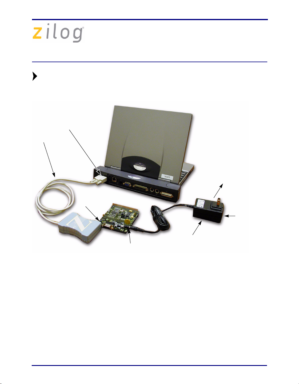
Setting up the Evaluation Board
The PC communicates with the Z8 Encore! XP F0822 Series Flash MCU evaluation board
using the serial port of the PC. A Z8 Encore! Smart Cable converts the RS-232 signals into
the 3.3 V bidirectional open-drain signal needed to communicate with the On-Chip
Debugger of the eZ8.
Caution:
Follow the steps below to setup the Z8 Encore! XP F0822 Series Flash MCU evaluation
board:
1. Connect the serial port of the PC to the Z8 Encore! Smart Cable DB-9 connector.
2. Connect the Z8 Encore! Smart Cable to the Z8 Encore! XP F0822 Series Flash MCU
evaluation board pin header P2.
3. Connect the power supply to the evaluation board at J1 (see Figure 1).
QS002507-1207 Page 2 of 9
Always use a grounding strap to prevent damage resulting from
electrostatic discharge (ESD).
Page 3
Z8 Encore! XP® F0822 Series Flash MCU Evaluation Kit
Note:
Smart
Cable
Depending up on which build of this kit you receive, it may contain either a
universal power supply containing two or four location-specific plug
configurations or a 110 V AC wall plug that cannot be modified.
Serial Port
Host PC
To Electrical
Outlet
Evaluation
Board
P2
HP Power
Cord
Receptacle
Universal
J1
Power Supply
Figure 1. Evaluation Board External Connections
Connecting the Universal Power Supply
There are two methods of connecting the universal power supply: the plug configurations
method or the Hewlett Packard power cord method.
Plug Configuration Method
The universal power supply kit features several different plug configurations in one box
and the power supply itself in another. The power supply ships with a slide-out plate that
must be removed to insert the location-specific plug configurations.
1. Remove the slide-out plate.
2. Select the plug configuration specific to the power requirements of your locale and
insert it into the slot that remains after removing the slide-out plate.
QS002507-1207 Page 3 of 9
Page 4

Z8 Encore! XP® F0822 Series Flash MCU Evaluation Kit
3. Slide the new plug configuration into the slot until it snaps into place.
4. Plug the power supply into an electrical outlet.
Hewlett Packard Power Cord Method
Follow the steps below to connect the Universal power supply by the Hewlett Packard
power cord method:
1. Attach a power cord (purchased separately) featuring an AC plug at one end and a
Hewlett Packard socket on the other end to the Hewlett Packard power cord receptacle
at the plug end of the power supply.
2. Plug the power supply into an electrical outlet.
Installing the ZDS II Z8 Encore! Software
Follow the steps below to install the ZDS II software:
1. Insert the ZDS II CD into the CD-ROM drive of the host PC. The CD launches
DemoShield automatically and provides a menu to install the product and
documentation. Select INSTALL PRODUCTS followed by INSTALL ZDS II to
display the Installation Wizard (see Figure 2).
Note:
Software versions displayed in the figure is for reference only. You may have
an updated version.
Figure 2. Installation Wizard (Reference Only)
QS002507-1207 Page 4 of 9
Page 5

Z8 Encore! XP® F0822 Series Flash MCU Evaluation Kit
2. Click Next to continue with the installation. The License Agreement appears.
3. Click Ye s to accept the agreement and proceed with the installation.
4. After selecting Ye s, the Choose Destination Location screen appears. Follow the
directions on the screen and choose whether to install ZDS II in the default location or
in some other folder. Click Next
.
5. The Select Program folder screen appears. Follow the directions on the screen and
click Next
.
6. After selecting Next, the Register Your Software screen appears. Follow the
on-screen instructions to complete registration.
7. If you elected not to register at this time, a reminder screen appears after installation
asking you to register the product online at www.zilog.com
. To register at a later time
the registration link to the internet site is found in the ZDS II Help menu.
8. When the installation is complete, the following directory is installed on the host PC,
presuming all installation settings remain at their defaults:
C:\Program Files\ZiLOG\ZDSII_<product>_<version number>.
Getting Started Using ZDS II
Follow the steps below to open and use an existing project:
1. Connect the Evaluation board to the host PC’s serial communications port using the
Smart Cable.
2. Apply power to the Evaluation board.
3. Run the ZDS II Software. By default, the ZDS II program is located in the Start menu
:
under
Start
<product><version number>.
QS002507-1207 Page 5 of 9
→ Programs → ZDS II_<product>_<version number>ZDS II
Page 6

Z8 Encore! XP® F0822 Series Flash MCU Evaluation Kit
4. Select Open Project from the File menu. The Open Project dialog box appears. See
Figure 3.
Figure 3. Open Project Dialog Box (Reference Only)
5. Browse to the samples directory:
c:\Program Files\ZiLOG\ZDSII_<product>_<version number>\Samples\.
6. Select Samples. The samples folder appears (See Figure 4).
Z8F08xx_ledBlink
Figure 4. Sample Directory (Reference Only)
7. Select the Z8F08xx_ledBlink folder and then the src folder to access the project file
containing
QS002507-1207 Page 6 of 9
ledBlink.pro (See Figure 5).
Page 7

Z8 Encore! XP® F0822 Series Flash MCU Evaluation Kit
Figure 5. src Folder (Reference Only)
8. Select the ledblink.pro file. The initial ZDS II program screen opens (See
Figure 6).
Figure 6. ZDS II Opening Screen (Reference Only)
QS002507-1207 Page 7 of 9
Page 8

Z8 Encore! XP® F0822 Series Flash MCU Evaluation Kit
9. Click the Rebuild All icon and then the Reset icon to connect and
download the code to the Evaluation board.
10. Click Go to start the program. The screen changes as displayed in
Figure 7.
Rebuild
All Icon
Reset
Icon
Go
Icon
Figure 7. ZDS II Active Screen
The three LEDs begin blinking in sequence. If the LEDs do not blink, start over from
Step 3.
QS002507-1207 Page 8 of 9
Page 9

Z8 Encore! XP® F0822 Series Flash MCU Evaluation Kit
Warning:
DO NOT USE IN LIFE SUPPORT
LIFE SUPPORT POLICY
ZILOG'S PRODUCTS ARE NOT AUTHORIZED FOR USE AS CRITICAL
COMPONENTS IN LIFE SUPPORT DEVICES OR SYSTEMS WITHOUT THE
EXPRESS PRIOR WRITTEN APPROVAL OF THE PRESIDENT AND GENERAL
COUNSEL OF ZILOG CORPORATION.
As used herein
Life support devices or systems are devices which (a) are intended for surgical implant
into the body, or (b) support or sustain life and whose failure to perform when properly
used in accordance with instructions for use provided in the labeling can be reasonably
expected to result in a significant injury to the user. A critical component is any
component in a life support device or system whose failure to perform can be reasonably
expected to cause the failure of the life support device or system or to affect its safety or
effectiveness.
Document Disclaimer
©2007 by Zilog, Inc. All rights reserved. Information in this publication concerning the
devices, applications, or technology described is intended to suggest possible uses and
may be superseded. ZILOG, INC. DOES NOT ASSUME LIABILITY FOR OR
PROVIDE A REPRESENTATION OF ACCURACY OF THE INFORMATION,
DEVICES, OR TECHNOLOGY DESCRIBED IN THIS DOCUMENT. ZILOG ALSO
DOES NOT ASSUME LIABILITY FOR INTELLECTUAL PROPERTY
INFRINGEMENT RELATED IN ANY MANNER TO USE OF INFORMATION,
DEVICES, OR TECHNOLOGY DESCRIBED HEREIN OR OTHERWISE. The
information contained within this document has been verified according to the general
principles of electrical and mechanical engineering.
Z8, Z8 Encore!, Z8 Encore! XP, Z8 Encore! MC, Crimzon, eZ80, and ZNEO are
trademarks or registered trademarks of Zilog, Inc. All other product or service names are
the property of their respective owners.
QS002507-1207 Page 9 of 9
 Loading...