

Page 1
Copyright ©2008 by Zilog®, Inc. All rights reserved.
www.zilog.com
Introduction
This User Manual describes how to setup and use Zilog’s Z8 Encore!® Smart Cable with
Z8 Encore!
development kit. This can also be used for Z8 Encore! XP® development kit.
The Z8 Encore! Smart Cable converts the RS-232 signals into the 3.3 V bidirectional
open-drain signals required to communicate using the DBG pin to the Zilog on-chip
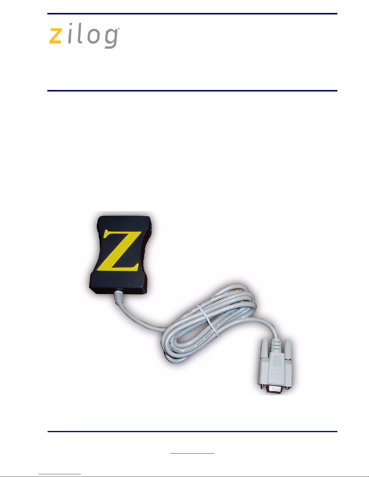
debugger of the Z8 Encore!. The Smart Cable features a 9-pin DB serial connector on one
end and a box with a 6-pin DBG Interface Connector on the other end.
The development kit includes the following (see Figure 1):
•Smart Cable
• User Manual
Figure 1. Z8 Encore! Smart Cable
Z8ENCORE000ZAC
Z8 Encore!
®
Smart Cable
User Manual
UM016207-0508
Page 2

Z8ENCORE000ZAC
Z8 Encore!
®
Smart Cable
UM016207-0508 Page 2 of 6
Voltage and Current Requirements
The voltage and current requirements of the Z8 Encore!® Serial Smart Cable include:
• System Clock: 153.6 kHz minimum, 20 MHz maximum
• Power Supply: 3.0 V minimum, 3.6 V maximum
• Current: 35 mA at 3.3 V
Connecting the Z8 Encore! Smart Cable to Your Computer
Connect the Z8 Encore! Smart Cable to a COM port on your computer using the 9-pin DB
serial connector (see Figure 2).
Figure 2. Connecting the Z8 Encore! Smart Cable to Your Computer
Connecting the Smart Cable to Your Development Board
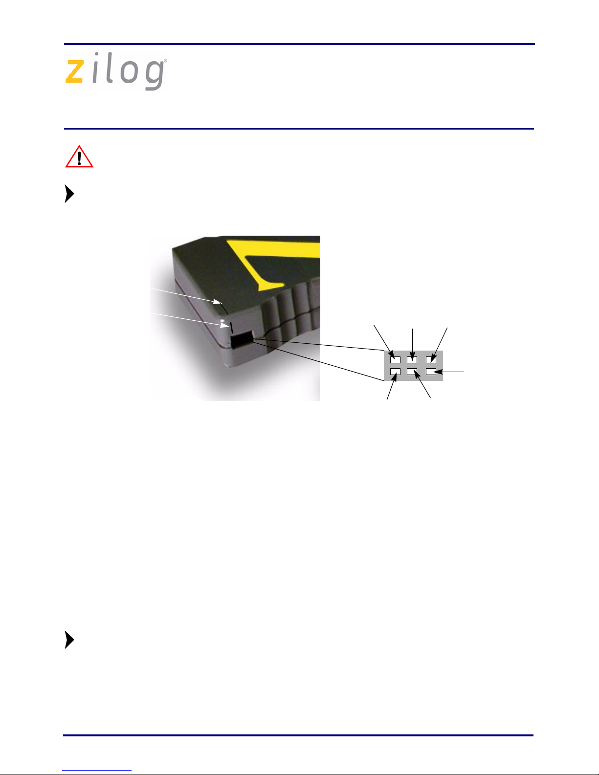
To use the Z8 Encore! Smart Cable, connect the application board to the Smart Cable 6-pin
DBG connector. Ensure that Pin 1 of the application lines up with Pin 1 of the DBG
connector, indicated by the horizontal/vertical groove over the Pin 1 placement (see
Figure 3 on page 3). For more information on interfacing the Smart Cable to your target
board, refer to Z8 Encore!
®
Design for Debug Technical Note (TN0036).
Power Supply
Development Board
Host PC
Serial Port
Smart Cable
(Not included)
(Not included)
(Not included)
Page 3
Z8ENCORE000ZAC
Z8 Encore!
®
Smart Cable
UM016207-0508 Page 3 of 6
The power to your design/application board must be turned OFF when
connecting or disconnecting the Smart Cable.
The Smart Cable receives power from the target design/application board.
Figure 3. DBG Interface Connector Pin 1 Location
Consider the following points when connecting the Smart Cable to your development
board:
• The DBG interface connector requires the V
DD
, VSS, and the DBG signals from the
Z8 Encore! on your design/application board.
• The minimum signal connections required to connect the Z8 Encore! to the Smart
Cable are the AV
DD
, VDD, AVSS, VSS, and the DBG pin signals.
•The AV
DD
must be externally connected to the VDD. The AVSS must also be
externally connected to the V
SS
.
• The Z8 Encore! must be clocked to generate the DBG timing signals. For the
recommended crystal oscillator circuit, refer to Product Specification of target MCU.
You must enter the crystal frequency running the Z8 Encore! device when creating a new project in ZDS II.
Follow the steps below to provide the crystal frequency:
1. Select Settings from the Project menu.
Caution:
Note:
Pin 1 Pin 5
Pin 6
Pin 3
Pin 2 Pin 4
Groove
Vertical
Horizontal
Groove
Note:
Page 4

Z8ENCORE000ZAC
Z8 Encore!
®
Smart Cable
UM016207-0508 Page 4 of 6
2. Select Configuration: Debug in the drop-down List box in the upper left corner of
the Settings dialog box.
3. Select Debugger → Target Name → Z8F64200100KITG or Z8F0800100KITG.
4. Select Debugger → Target → Setup.
5. Select either Clock Frequency or Other. If you select Other, enter the X1 Crystal
frequency in units of MHZ. Click OK.
6. Select Debugger → Debug Tool → SerialSmartCable.
7. Select Debugger → Debug Tool → Setup.
8. Select the appropriate COM port and Baud Rate.
Figure 4 displays the connection of Smart Cable and Z8 Encore!
®
device.
Figure 4. Connection Between Smart Cable and Z8 Encore!
Device
Page 5

Z8ENCORE000ZAC
Z8 Encore!
®
Smart Cable
UM016207-0508 Page 5 of 6
Compatibility with Microsoft Operating Systems
The Z8 Encore!
®
Smart Cable is compatible with the following Microsoft operating sys-
tems when connected directly to the serial port of the PC:
•WIN98E
•WIN NT
• WIN2000
•WIN XP
• WIN VISTA
Page 6

Z8ENCORE000ZAC
Z8 Encore!
®
Smart Cable
UM016207-0508 Page 6 of 6
DO NOT USE IN LIFE SUPPORT
LIFE SUPPORT POLICY
ZILOG'S PRODUCTS ARE NOT AUTHORIZED FOR USE AS CRITICAL
COMPONENTS IN LIFE SUPPORT DEVICES OR SYSTEMS WITHOUT THE
EXPRESS PRIOR WRITTEN APPROVAL OF THE PRESIDENT AND GENERAL
COUNSEL OF ZILOG CORPORATION.
As used herein
Life support devices or systems are devices which (a) are intended for surgical implant
into the body, or (b) support or sustain life and whose failure to perform when properly
used in accordance with instructions for use provided in the labeling can be reasonably
expected to result in a significant injury to the user. A critical component is any
component in a life support device or system whose failure to perform can be reasonably
expected to cause the failure of the life support device or system or to affect its safety or
effectiveness.
Document Disclaimer
©2008 by Zilog, Inc. All rights reserved. Information in this publication concerning the
devices, applications, or technology described is intended to suggest possible uses and
may be superseded. ZILOG, INC. DOES NOT ASSUME LIABILITY FOR OR
PROVIDE A REPRESENTATION OF ACCURACY OF THE INFORMATION,
DEVICES, OR TECHNOLOGY DESCRIBED IN THIS DOCUMENT. ZILOG ALSO
DOES NOT ASSUME LIABILITY FOR INTELLECTUAL PROPERTY
INFRINGEMENT RELATED IN ANY MANNER TO USE OF INFORMATION,
DEVICES, OR TECHNOLOGY DESCRIBED HEREIN OR OTHERWISE. The
information contained within this document has been verified according to the general
principles of electrical and mechanical engineering.
Z8, Z8 Encore!, and Z8 Encore! XP are registered trademarks of Zilog, Inc. All other
product or service names are the property of their respective owners.
Warning:Warning:
Page 7

Mouser Electronics
Authorized Distributor
Click to View Pricing, Inventory, Delivery & Lifecycle Information:
ZiLOG:
Z8ENCORE000ZAC
 Loading...