

Page 1

查询Z86D990HZ008SC供应商
Z86D990/Z86D 99 1 OT P an d
Z86L99X ROM
Low-Voltage Microcontrollers with ADC
Preliminary Product Specification
PS003807-1002
ZiLOG Worldwide Headquarters • 532 Race Street • San Jose, CA 95126-3432
Telephone: 408.558.8500 • Fax: 408.558.8300 • www.ZiLOG.com
Page 2

This publication is subject to replacement by a later edition. To determine whether
a later edition exists, or to request copies of publications, contact:
ZiLOG Worldwide Headquarters
532 Race Street
San Jose, CA 95126-3432
Telephone: 408.558.8500
Fax: 408.558.8300
www.ZiLOG.com
ZiLOG is a registered trademark of ZiLOG Inc. in the United States and in other countries. All other
products and/or service names mentioned herein may be trademarks of the companies with which
they are associated.
Document Disclaimer
© 2002 by ZiLOG, Inc. All rights reserved. Information in this publication concerning the devices,
applications, or techn ology descri bed is i ntended to sugge st pos sible uses an d may be supers eded.
ZiLOG, INC. DOES NOT ASSUME LIABILITY FOR OR PROVIDE A REPRESENTATION OF
ACCURACY OF THE INFORMATION, DEVICES, OR TECHNOLOGY DESCRIBED IN THIS
DOCUMENT. ZiLOG ALSO DOES NOT ASSUME LIABILITY FOR INTELLECTUAL PROPERTY
INFRINGEMENT RELATED IN ANY MANNER TO USE OF INFORMATION, DEVICES, OR
TECHNOLOGY DESCRIBED HEREIN OR OTHERWISE. Except with the express written approval
ZiLOG, use of information, devices, or technology as critical components of life support systems is
not authorized. No licenses or other rights are conveyed, implicitly or otherwise, by this document
under any intellectual property rights.
P R E L I M I N A R Y PS003807-1002
Page 3

Table of Contents
Architectural Overview . . . . . . . . . . . . . . . . . . . . . . . . . . . . . . . . . . . . . . . . . . . . 1
Features . . . . . . . . . . . . . . . . . . . . . . . . . . . . . . . . . . . . . . . . . . . . . . . . . . . . . . . 2
Counter/Timers . . . . . . . . . . . . . . . . . . . . . . . . . . . . . . . . . . . . . . . . . . . . . . . 2
Input/Output and Interrupts . . . . . . . . . . . . . . . . . . . . . . . . . . . . . . . . . . . . . . 2
Operating Characteristics . . . . . . . . . . . . . . . . . . . . . . . . . . . . . . . . . . . . . . . 3
User-Programmable Option Bits . . . . . . . . . . . . . . . . . . . . . . . . . . . . . . . . . . 3
Functional Block Diagram . . . . . . . . . . . . . . . . . . . . . . . . . . . . . . . . . . . . . . . . . . 4
Pin Descriptions . . . . . . . . . . . . . . . . . . . . . . . . . . . . . . . . . . . . . . . . . . . . . . . . . 5
Pins Configuration . . . . . . . . . . . . . . . . . . . . . . . . . . . . . . . . . . . . . . . . . . . . . 7
Operational Description . . . . . . . . . . . . . . . . . . . . . . . . . . . . . . . . . . . . . . . . . . . . 9
Central Proc es s in g U n it (C PU) Description . . . . . . . . . . . . . . . . . . . . . . . . . . 9
Memory (ROM/OTP and RAM) . . . . . . . . . . . . . . . . . . . . . . . . . . . . . . . . . . 10
Clock Circuit Description . . . . . . . . . . . . . . . . . . . . . . . . . . . . . . . . . . . . . . . 14
Interrupts . . . . . . . . . . . . . . . . . . . . . . . . . . . . . . . . . . . . . . . . . . . . . . . . . . . 15
Reset Conditions . . . . . . . . . . . . . . . . . . . . . . . . . . . . . . . . . . . . . . . . . . . . . 19
Power Management . . . . . . . . . . . . . . . . . . . . . . . . . . . . . . . . . . . . . . . . . . 22
I/O Ports . . . . . . . . . . . . . . . . . . . . . . . . . . . . . . . . . . . . . . . . . . . . . . . . . . . 24
Peripherals . . . . . . . . . . . . . . . . . . . . . . . . . . . . . . . . . . . . . . . . . . . . . . . . . 28
Z86D990/Z86D991 OTP and Z86L99X ROM
Low-Voltage Microcontrollers with ADC
iii
Control and Status Registers . . . . . . . . . . . . . . . . . . . . . . . . . . . . . . . . . . . . . . 52
Register Summary . . . . . . . . . . . . . . . . . . . . . . . . . . . . . . . . . . . . . . . . . . . . 52
Register Error Conditions . . . . . . . . . . . . . . . . . . . . . . . . . . . . . . . . . . . . . . 54
Registers (Grouped by Function) . . . . . . . . . . . . . . . . . . . . . . . . . . . . . . . . 55
Electrical Characteristics . . . . . . . . . . . . . . . . . . . . . . . . . . . . . . . . . . . . . . . . . . 85
Absolute Maximum Ratings . . . . . . . . . . . . . . . . . . . . . . . . . . . . . . . . . . . . . 85
Standard Test Conditions . . . . . . . . . . . . . . . . . . . . . . . . . . . . . . . . . . . . . . 85
DC Characteristics . . . . . . . . . . . . . . . . . . . . . . . . . . . . . . . . . . . . . . . . . . . 86
Analog-to-D i gi ta l C o n v e rte r Ch aracteristic s . . . . . . . . . . . . . . . . . . . . . . . . 89
AC Characteristics . . . . . . . . . . . . . . . . . . . . . . . . . . . . . . . . . . . . . . . . . . . . 90
Packaging . . . . . . . . . . . . . . . . . . . . . . . . . . . . . . . . . . . . . . . . . . . . . . . . . . . . . 91
Design Considerations . . . . . . . . . . . . . . . . . . . . . . . . . . . . . . . . . . . . . . . . . . . 94
Ordering Information . . . . . . . . . . . . . . . . . . . . . . . . . . . . . . . . . . . . . . . . . . . . . 95
Precharacterization Product . . . . . . . . . . . . . . . . . . . . . . . . . . . . . . . . . . . . . . . 95
PS003807-1002 P R E L I M I N A R Y
Page 4

List of Figures
Figure 1. Functional Block Diagram . . . . . . . . . . . . . . . . . . . . . . . . . . . . . . . . . 4
Figure 2. 48-Pin SSOP P in A ss ig n ments . . . . . . . . . . . . . . . . . . . . . . . . . . . . . 5
Figure 3. 40-Pin DIP Pin Assignment . . . . . . . . . . . . . . . . . . . . . . . . . . . . . . . . 6
Figure 4. 28-Pin SOIC/DIP Pin Assignment—User Mode . . . . . . . . . . . . . . . . 7
Figure 5. Program Memory Map . . . . . . . . . . . . . . . . . . . . . . . . . . . . . . . . . . . 12
Figure 6. Standard Z8 Register File (Working Reg. Groups 0–F, Bank 0) . . . 13
Figure 7. Z8 Expanded Register File Architecture . . . . . . . . . . . . . . . . . . . . . 14
Figure 8. Interrupt Block Diagram . . . . . . . . . . . . . . . . . . . . . . . . . . . . . . . . . . 16
Figure 9. External Interrupt Sources IRQ0–IRQ2 Block Diagram . . . . . . . . . . 17
Figure 10. IRQ Logic . . . . . . . . . . . . . . . . . . . . . . . . . . . . . . . . . . . . . . . . . . . . . 18
Figure 11. Interrupt Request Timi ng . . . . . . . . . . . . . . . . . . . . . . . . . . . . . . . . . 18
Figure 12. General Input/Output Pin . . . . . . . . . . . . . . . . . . . . . . . . . . . . . . . . . 26
Figure 13. Analog Comparators . . . . . . . . . . . . . . . . . . . . . . . . . . . . . . . . . . . . 28
Figure 14. AD C Bl o c k D ia g r am . . . . . . . . . . . . . . . . . . . . . . . . . . . . . . . . . . . . . 29
Figure 15. Lo w -Pa s s Filter (with 8-MHz Crystal) . . . . . . . . . . . . . . . . . . . . . . . 30
Figure 16. Active Glitch/Power Filter . . . . . . . . . . . . . . . . . . . . . . . . . . . . . . . . 32
Figure 17. I-V Characteristics fo r the Current Sink Pad P43 . . . . . . . . . . . . . . 34
Figure 18. T
Figure 19. Register File . . . . . . . . . . . . . . . . . . . . . . . . . . . . . . . . . . . . . . . . . . 36
Figure 20. Pre s c a le r 1 Reg i ster . . . . . . . . . . . . . . . . . . . . . . . . . . . . . . . . . . . . 36
Figure 21. Counter/Timer 1 Register . . . . . . . . . . . . . . . . . . . . . . . . . . . . . . . . 37
Figure 22. Timer Mode Register . . . . . . . . . . . . . . . . . . . . . . . . . . . . . . . . . . . . 37
Figure 23. Starting the Count . . . . . . . . . . . . . . . . . . . . . . . . . . . . . . . . . . . . . . 38
Figure 24. Counting Modes . . . . . . . . . . . . . . . . . . . . . . . . . . . . . . . . . . . . . . . 39
Figure 25. Timer Mode Register T
Figure 26. Counter/Timer Output Using T
Figure 27. Internal Clock Output Using T
Figure 28. Timer Mode Register T
Figure 29. Prescaler 1 T
Figure 30. External Clock Input Mode . . . . . . . . . . . . . . . . . . . . . . . . . . . . . . . 43
Figure 31. Gated Clock Input Mode . . . . . . . . . . . . . . . . . . . . . . . . . . . . . . . . . 43
Figure 32. Triggered Clock Mode . . . . . . . . . . . . . . . . . . . . . . . . . . . . . . . . . . . 44
Figure 33. Counter/Timer Archit ecture . . . . . . . . . . . . . . . . . . . . . . . . . . . . . . . 46
Figure 34. Transmit Mode Flowchart . . . . . . . . . . . . . . . . . . . . . . . . . . . . . . . . 48
Counter/Timer Block Diagram . . . . . . . . . . . . . . . . . . . . . . . . . . . 35
1
Z86D990/Z86D991 OTP and Z86L99X ROM
Low-Voltage Microcontrollers with ADC
Operation . . . . . . . . . . . . . . . . . . . . . . . 4 0
OUT
. . . . . . . . . . . . . . . . . . . . . . . . . 41
OUT
. . . . . . . . . . . . . . . . . . . . . . . . . . 41
OUT
Operation . . . . . . . . . . . . . . . . . . . . . . . . 42
IN
Operation . . . . . . . . . . . . . . . . . . . . . . . . . . . . . . . . 42
IN
iv
PS003807-1002 P R E L I M I N A R Y
Page 5

Z86D990/Z86D991 OTP and Z86L99X ROM
Low-Voltage Microcontrollers with ADC
Figure 35. Demodulation Mode Flowchart . . . . . . . . . . . . . . . . . . . . . . . . . . . . 50
Figure 36. Test Load Diagram . . . . . . . . . . . . . . . . . . . . . . . . . . . . . . . . . . . . . 86
Figure 37. 48-Pin SSOP . . . . . . . . . . . . . . . . . . . . . . . . . . . . . . . . . . . . . . . . . . 91
Figure 38. 40-Pin PDIP . . . . . . . . . . . . . . . . . . . . . . . . . . . . . . . . . . . . . . . . . . . 92
Figure 39. 28-Pin PDIP . . . . . . . . . . . . . . . . . . . . . . . . . . . . . . . . . . . . . . . . . . . 92
Figure 40. 28-Pin SOIC . . . . . . . . . . . . . . . . . . . . . . . . . . . . . . . . . . . . . . . . . . 93
v
PS003807-1002 P R E L I M I N A R Y
Page 6

List of Tables
Table 1. Z86L99/Z 8 6D99 Feature Com p a ri so n . . . . . . . . . . . . . . . . . . . . . . . . 1
Table 2. Pin Descriptions . . . . . . . . . . . . . . . . . . . . . . . . . . . . . . . . . . . . . . . . . 7
Table 3. Interrupt Types, Sources, and Vectors . . . . . . . . . . . . . . . . . . . . . . 15
Table 4. Interrupt Edge Select for External Interrupts . . . . . . . . . . . . . . . . . . 17
Table 5. Control and Stat us Reg ist er Reset Conditions . . . . . . . . . . . . . . . . 20
Table 6. Clock Status in Operating Modes . . . . . . . . . . . . . . . . . . . . . . . . . . 22
Table 7. Special Port Pin Functions . . . . . . . . . . . . . . . . . . . . . . . . . . . . . . . 27
Table 8. Active Glitch /F il te r S p e c ifi ca t io n s (P re li m in a r y) . . . . . . . . . . . . . . . . 32
Table 9. Current Sink Pad P43 Specifi cations (Preliminary) . . . . . . . . . . . . . 33
Table 10. I/O Port Registers (Group 0, Bank 0, Registers 0–F) . . . . . . . . . . . 52
Table 11. Timer Control Registers (Group 0, Bank D, Registers 0–F) . . . . . . 53
Table 12. Control and Status Registers (Group F, Bank 0,
Registers 0–F) . . . . . . . . . . . . . . . . . . . . . . . . . . . . . . . . . . . . . . . . . 53
Table 13. SMR and Port Mode Registers (Group 0, Bank F,
Registers 0–F) . . . . . . . . . . . . . . . . . . . . . . . . . . . . . . . . . . . . . . . . . 54
Table 14. Register Description Locations . . . . . . . . . . . . . . . . . . . . . . . . . . . . 55
Table 15. FLAGS Register [Group/Bank F0h, Register C (R252)] . . . . . . . . . 57
Table 16. RP Register [Group/Bank F0h, Register D (R253)] . . . . . . . . . . . . . 58
Table 17. SP Register [Group/Bank F0h, Register F (R255)] . . . . . . . . . . . . . 59
Table 18. LB Register (Group/Bank 0Dh, Register C) . . . . . . . . . . . . . . . . . . . 60
Table 19. ADCCTRL Register (Group/Bank 0Fh, Register 8) . . . . . . . . . . . . . 61
Table 20. ADCDATA Register (Group/Bank 00h, Register 7) . . . . . . . . . . . . . 62
Table 21. IMR (Group/Bank 0Fh, Register B) . . . . . . . . . . . . . . . . . . . . . . . . . 63
Table 22. IPR (Group/Bank 0Fh, Register 9) . . . . . . . . . . . . . . . . . . . . . . . . . 64
Table 23. IRQ (Group/Bank 0Fh, Register A) . . . . . . . . . . . . . . . . . . . . . . . . . 65
Table 24. P456CON Register (Group/Bank 0Fh, Register 0) . . . . . . . . . . . . . 67
Table 25. P3M Register [Group/Bank F0h, Register 7 (R247)] . . . . . . . . . . . . 68
Table 26. P2 Register [Group/Bank 00h, Register 2 (R2)] . . . . . . . . . . . . . . . 68
Table 27. P2M Register [Group/Bank F0h, Register 6 (R246)] . . . . . . . . . . . . 68
Table 28. P4 Register [Group/Bank 00h, Register 4 (R4)] . . . . . . . . . . . . . . . 69
Table 29. P4M Register (Group/Bank 0Fh, Register 2) . . . . . . . . . . . . . . . . . . 69
Table 30. P5 Register [Group/Bank 00h, Register 5 (R5)] . . . . . . . . . . . . . . . 70
Table 31. P5M Register (Group/Bank 0Fh, Register 4) . . . . . . . . . . . . . . . . . . 70
Table 32. P6 Register [Group/Bank 00h, Register 6 (R6)] . . . . . . . . . . . . . . . 71
Z86D990/Z86D991 OTP and Z86L99X ROM
Low-Voltage Microcontrollers with ADC
vi
PS003807-1002 P R E L I M I N A R Y
Page 7

Z86D990/Z86D991 OTP and Z86L99X ROM
Low-Voltage Microcontrollers with ADC
Table 33. P6M Register (Group/Bank 0Fh, Register 6) . . . . . . . . . . . . . . . . . . 71
Table 34. T1 Register [Group/Bank F0h, Register 2 (R242)] . . . . . . . . . . . . . 72
Table 35. TMR Register [Group/Bank F0h, Register 1 (R241)] . . . . . . . . . . . . 72
Table 36. PRE1 Register [Group/Bank F0h, Register 3 (R243)] . . . . . . . . . . . 73
Table 37. CTR1 Register (In Transmit Mode)
(Group/Bank 0Dh, Register 1) . . . . . . . . . . . . . . . . . . . . . . . . . . . . . 74
Table 38. CTR1 Register (in Demodulation Mode)
(Group/Bank 0Dh, Register 1) . . . . . . . . . . . . . . . . . . . . . . . . . . . . . 75
Table 39. CTR3 Register (Group/Bank 0Dh, Register 3) . . . . . . . . . . . . . . . . 76
Table 40. CTR0 Register (Group/Bank 0Dh, Register 0) . . . . . . . . . . . . . . . . 77
Table 41. HI8 Register (Group/Bank 0Dh, Register B) . . . . . . . . . . . . . . . . . . 78
Table 42. LO8 Register (Group/Bank 0Dh, Register A) . . . . . . . . . . . . . . . . . . 78
Table 43. TC8H Register (Group/Bank 0Dh, Register 5) . . . . . . . . . . . . . . . . 79
Table 44. TC8L Register (Group/Bank 0Dh, Register 4) . . . . . . . . . . . . . . . . . 79
Table 45. CTR2 Register (Group/Bank 0Dh, Register 2) . . . . . . . . . . . . . . . . 80
Table 46. HI16 Register (Group/Bank 0Dh, Register 9) . . . . . . . . . . . . . . . . . 81
Table 47. LO16 Register (Group/Bank 0Dh, Register 8) . . . . . . . . . . . . . . . . . 81
Table 48. TC16H Register (Group/Bank 0Dh, Register 7) . . . . . . . . . . . . . . . 82
Table 49. TC16L Register (Group/Bank 0Dh, Register 6) . . . . . . . . . . . . . . . . 82
Table 50. SMR Register (Group/Bank 0Fh, Register B) . . . . . . . . . . . . . . . . . 83
Table 51. P2SMR Register (Group/Bank 0Fh, Register 1) . . . . . . . . . . . . . . . 84
Table 52. P5SMR Register (Group/Bank 0Fh, Register 5) . . . . . . . . . . . . . . . 84
Table 53. Absolute Maximum Ratings . . . . . . . . . . . . . . . . . . . . . . . . . . . . . . . 85
Table 54. DC Characteristics for the Z86D99X (OTP Only) . . . . . . . . . . . . . . 87
Table 55. DC Characteristics for the Z86L99X (Mask Only) . . . . . . . . . . . . . . 88
Table 56. Analog-to-Digital Converter Characteristics . . . . . . . . . . . . . . . . . . . 89
Table 57. AC Characteristics . . . . . . . . . . . . . . . . . . . . . . . . . . . . . . . . . . . . . . 90
vii
PS003807-1002 P R E L I M I N A R Y
Page 8

Architectur al Overview
Z86D990/Z86D991 OTP and Z86L99X ROM
Low-Voltage Microcontrollers with ADC
1
The Z86D99 is a low-voltage general-purpose one-time programmable (OTP) Z8
microcontroller with an integrat ed four-channel 8-bit sigma delta analog-to-digital
converter. The Z86L99 is the read-only memory (ROM) version of this controller.
The Z86D99/Z86L99 family is designed to be used i n a wide vari ety of embedded
control applications including battery chargers, home appliances, infrare d (IR)
remote controls, security systems, and wire less keyboards.
It has three counter/timers, a general- purpose 8-bit counter/ti mer with a 6-bit pres caler and an 8-bit/16-bit counter/timer pair that can be used individually for general-purpose timing or as a pair to automate the generation and reception of
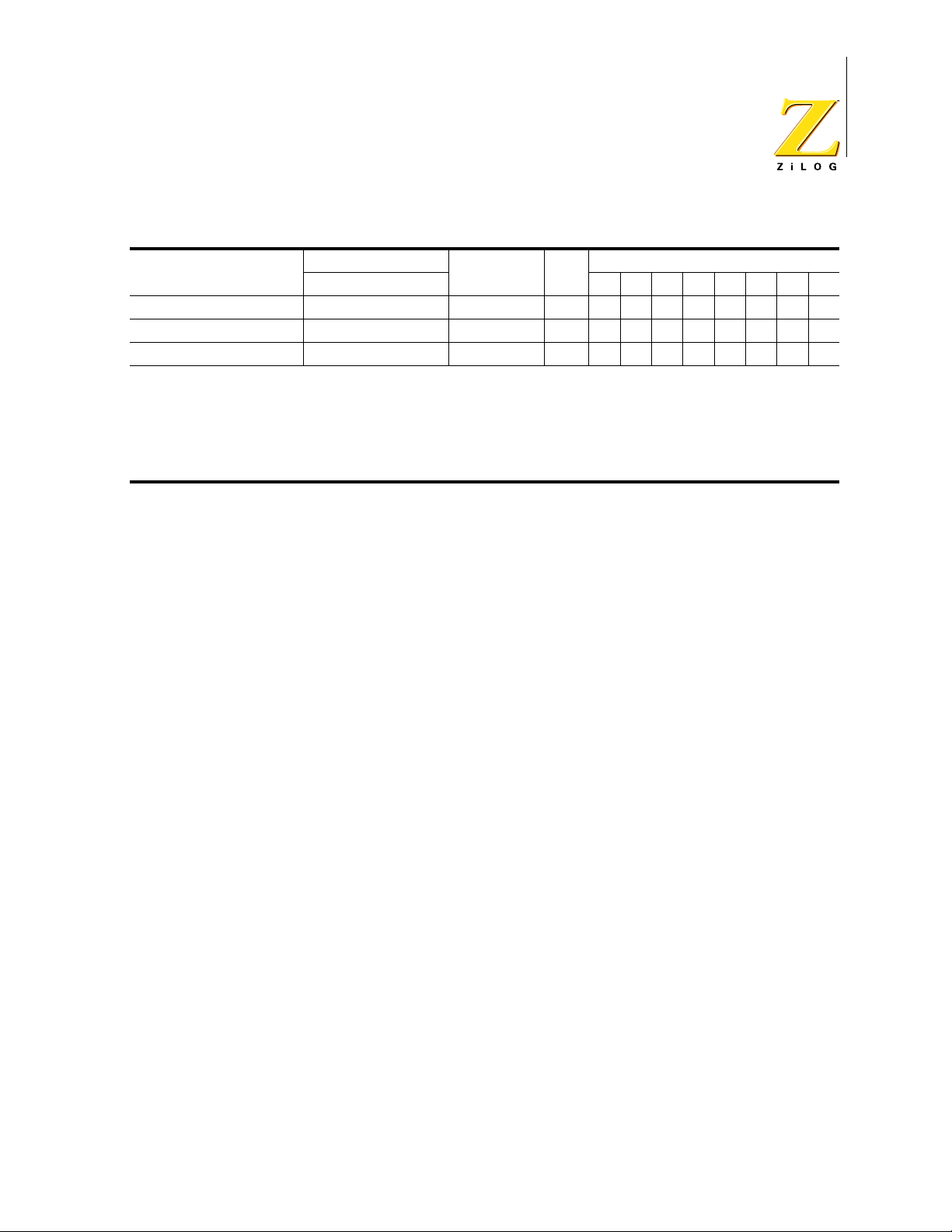
complex pulses or signals. Unique features of the Z86D99/Z86L99 family of products include 489 bytes of general-purpose random-access memory (RAM), 256
bytes of which are mapped into the program memory space and can be used to
store data variables or as executable RAM, a low-battery detection flag, and a
controlled current output pin, which is a regulated current source that sinks a predefined current (I
). Table 1 highlights the basic product features of these
CCO
microcontrollers.
Table 1. Z86L99/Z86D99 Feature Comparison
Pins I/O
Memory
(Bytes)
Operating
Voltage (V) ADC Timers
Watch-Dog
Timer
®
Z86D990 40/48 32 32K OTP 3.0–5.5 4 channel 3 Yes
Z86D991 28 24 32K OTP 3.0–5.5 — 3 Yes
Z86L990 40/48 32 16K ROM 2.3–5.5 4 channel 3 Yes
Z86L991 28 24 16K ROM 2.3–5.5 — 3 Yes
Z86L996 28 24 4K ROM 2.3–5.5 — 3 Yes
Z86L997 28 24 8K ROM 2.3–5.5 — 3 Yes
The Z8 microcontroller core of fers more flexibility and performance than accumulator-based microcontroll ers. All 256 general-purpose registers, including dedicated input/output (I/O) port registers, can be used as accumulators. This unique
register-to-register architecture avoids accumulator bottlenecks for high code efficiency. The registers can be used as address pointers for indirect addressing, as
index registers, or for implement ing an on-chip stack.
The Z8 has a sophisticated interrupt structur e and automatically saves the program counter and status flags on the st ack for fast context-switching. Speed of
execution and smooth programming are also supported by a “working register
area” with short 4-bit register addresses.
PS003807-1002 P R E L I M I N A R Y
Page 9

Features
Z86D990/Z86D991 OTP and Z86L99X ROM
Low-Voltage Microcontrollers with ADC
The Z8 instruction set, consisting o f 43 basic instructions, is optimized for highcode density and reduced execution time. It is similar in form to the ZiLOG Z80
instruction set. The eight instruction types and six addressing modes together
with the ability to operate on bits, 4-bit nibbles or binary coded decimal (BCD) digits, 8-bit bytes, and 16-bit words, make for a code-ef fi cient, fl exible micr ocontro ller.
•
Four-channel, 8-bit sigma delta analog-to-digital (A/D) converter wit h external
voltage references (no t avai lable in the 28-pin configuration)
•
Two independent analog comparators
•
Controlled current output
2
•
489 bytes of RAM
–
233 bytes of general-purpose register-based RAM
–
256 bytes of RAM mapped into the program memory space that can be
used as data RAM or executable RAM
•
32 Kbytes of OTP memory (Z86D99X)
•
16 Kbytes of ROM (Z86L99X)
Counter/Timers
•
Special architecture to automate generation and reception of complex pulses
or signals:
–
Programmable 8-bit counter/time r (T8) with two 8-bit c apture r egisters and
two 8-bit load registers
–
Programmable 16-bit counter/timer (T16) with one 16-bit capture register
pair and one 16-bit load register pair
–
Programmable input glitch filter for pulse reception
•
One general-purpose 8-bit counter/timer (T1) with 6-bit prescaler
Input/Output and Interrupts
•
Thirty-two I/Os, twenty- ni ne of which ar e bidi recti onal I /Os wi th programmable
resistive pull-up transistors (24 I/Os are available in the 28-pin configuration)
•
Sixteen I/Os are selectable as stop-mode recovery sources
•
Six interrupt vectors with nine i nterrupt sources
–
Three external sources
–
Two comparator interrupts
PS003807-1002 P R E L I M I N A R Y
Page 10

–
Three timer interrupts
–
One low-battery detector flag
Operating Characteristics
•
8-MHz operation
•
3.0 V to 5.5 V operating voltage (Z86D990/Z86D991)
•
2.3 V to 5.5 V operating voltage (Z86L990/Z86L991)
•
Low power consumption with three standby modes:
–
Stop
–
Halt
–
Low Vol tage Standby
Z86D990/Z86D991 OTP and Z86L99X ROM
Low-Voltage Microcontrollers with ADC
3
•
Low-battery detection flag
•
Low-voltage protection circ uit (also known as VBO, or voltage brownout,
circuit)
•
Watch-dog timer and power-on reset circuits
User-Programmable Option Bits
•
Clock source—RC/other (LC, resonator, or crystal)
•
Watch-dog timer permanently enable
•
32-kHz crystal
•
Port 20–27 pull-up resistive transistor
•
Port 40–42 pull-up resistive transistor
•
Port 44–47 pull-up resistive transistor
•
Port 50–51 pull-up resistive transistor
•
Port 54–57 pull-up resistive transistor
•
Port 60–63 pull-up resistive transistor (not available in Z86D991/Z86L991)
•
Port 64–67 pull-up resistive transistor (not available in Z86D991/Z86L991)
•
P43 high impedance in STOP mode (available in OTP only)
Force P43 to output a 1 in the open-drain configuration
PS003807-1002 P R E L I M I N A R Y
Page 11
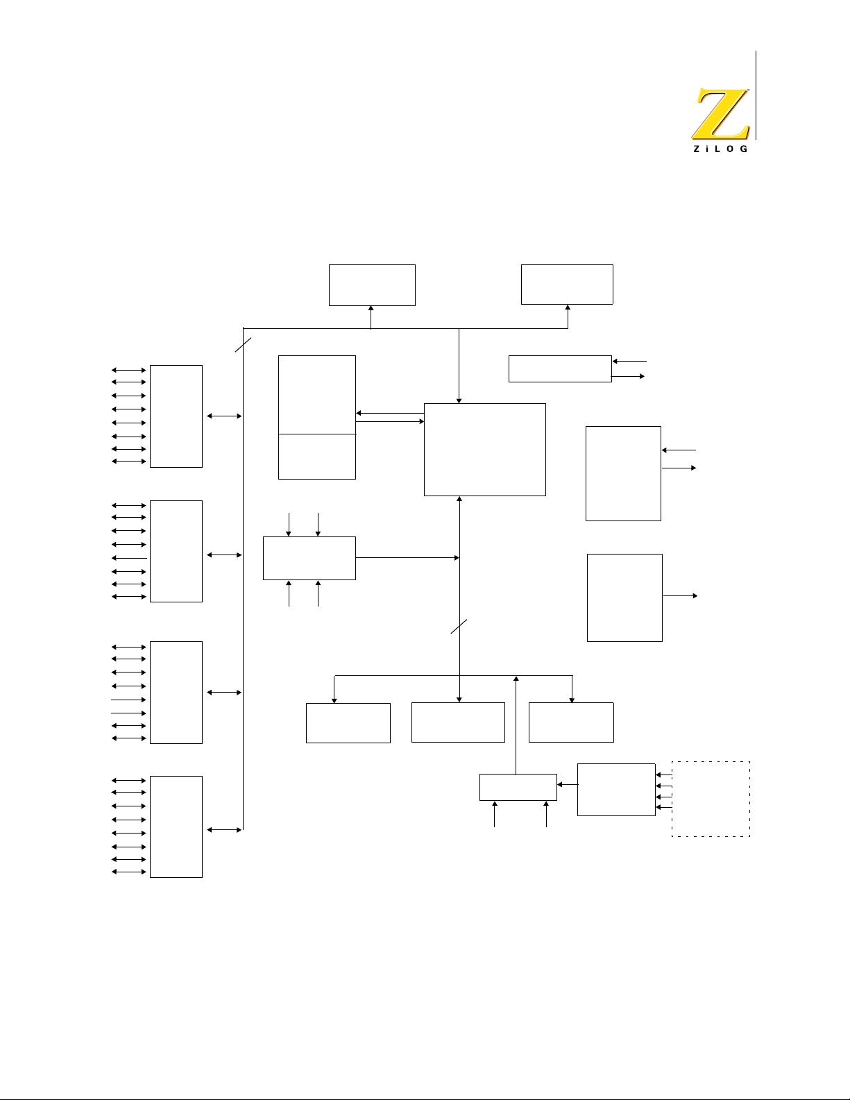
Functional Block Diagra m
Figure 1 shows the functional block diagram for the microcontrollers.
Z86D990/Z86D991 OTP and Z86L99X ROM
Low-Voltage Microcontrollers with ADC
4
Register File
256 x 8-bit
Expanded
Register File
8
V
7
Program
Memory
Power Filter
DD_padring
V
DD_CORE
***
††
Port 2
Machine
0
7
*
Port 4
256 Bytes
P52
CIN2
P53
CREF2
Two Analog
Comparators
Z8 Core
Timing
and
Instruction
Control
XTAL 1
XTAL 2
Controlled
0
CIN1
P51
CREF1
P50
8
Current
Output
P43
7
Port 5
8-Bit C/T
0
(Carrier)
7
Port 6
**
0
*Controlled Current Output
**P6 is only in the Z86L990/Z86D990.
***In the 28-pin package, V
DD_padring
are bonded together.
and V
16-Bit C/T
(Modulation)
DD_CORE
8-Bit A/D†
V
Ref+
†ADC is only in the Z86L990/Z86D990.
††Program memory is as follows:
8-Bit C/T
(General)
V
Ref–
Z86D990 32K OTP
Z86D991 32K OTP
Z86L990 16K ROM
Z86L991 16K ROM
Figure 1. Functional Block Diagram
PS003807-1002 P R E L I M I N A R Y
MUX
ADC0/P44
ADC1/P45
ADC2/P46
ADC3/P47
Page 12

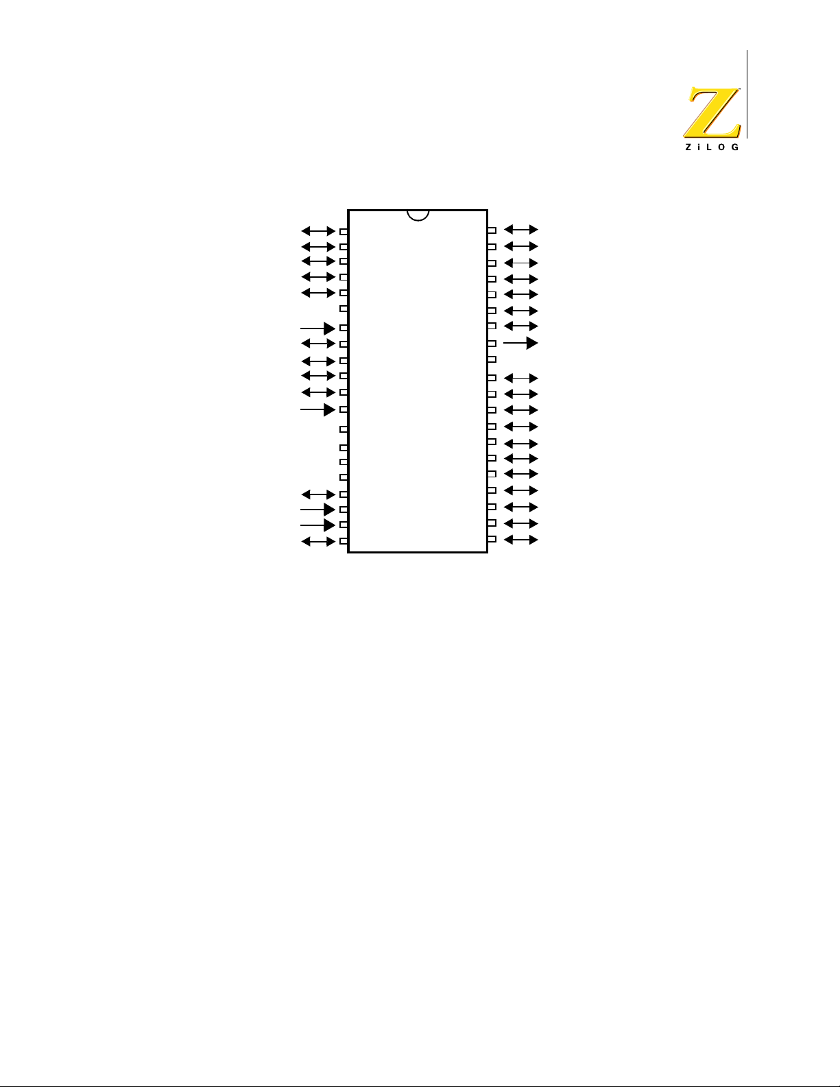
Pin Descriptions
Figure 2 through Figure 4 show the pin names and locations.
Z86D990/Z86D991 OTP and Z86L99X ROM
Low-Voltage Microcontrollers with ADC
5
AV
V
V
AV
V
DD_CORE
V
DD_padring
XTAL2
XTAL1
P62
P63
P25
P26
P27
NC
SS
REF-
P44
P45
P46
P47
REF+
DD
NC
P51
P52
P53
P54
P64
1
2
3
4
5
6
7
8
9
10
Z86D990/
11
Z86L990
12
13
14
15
16
17
18
19
20
21
22
23
24 25
48
47
46
45
44
43
42
41
40
39
38
37
36
35
34
33
32
31
30
29
281
27
26
P61
P60
P24
P23
P22
NC
NC
P21
P20
P43
VSS
VSS
P42
P41
P40
P50
P56
NC
NC
P57
P55
P67
P66
P65
Notes:
1. Both VSS pins must be connected to ground.
2. NC is no connection to the die.
3. AV
must be connected to V
DD
4. Power must be connected to V
DD_CORE
DD_padring
and a 10-µF capacitor for good A/D conversion.
. Current passes to V
DD_CORE
power filter.
Figure 2. 48-Pin SSOP Pin Assignments
PS003807-1002 P R E L I M I N A R Y
through the internal
Page 13
Z86D990/Z86D991 OTP and Z86L99X ROM
Low-Voltage Microcontrollers with ADC
6
P62
P63
P25
P26
P27
AV
SS
V
Ref–
P44/ADC0
P45/ADC1
P46/ADC2
P47/ADC3
V
Ref+
AVDD/V
P51/CIN1/Captive T imer Inp ut
P52/CIN2/T1 Timer Input (TIN)
DD_CORE
V
DD_padring
XTAL2
XTAL1
P53/CREF2
P54/COUT1
Notes:
1. AVDD must be connected to V
2. Power must be connected to V
power filter.
1
2
3
4
Z86D990/
5
Z86L990
6
7
8
9
10
11
12
13
14
15
16
17
18
19
20 21
DD_CORE
DD_padring
and a 10-µF capacitor for good A/D conversion.
. Current passe s to V
40
39
38
37
36
35
34
33
31
30
29
28
27
26
25
24
23
22
32
P61
P60
P24
P23
P22
P21
P20
P43/Combined T8 T16 Output
V
SS
P42
P41/T16 Output
P40/T8 Output
P50/CREF1
P56/T1 Timer Output
P57
P55/COUT2
P67
P66
P65
P64
DD_CORE
through the internal
Figure 3. 40-Pin DIP Pin Assignment
PS003807-1002 P R E L I M I N A R Y
Page 14
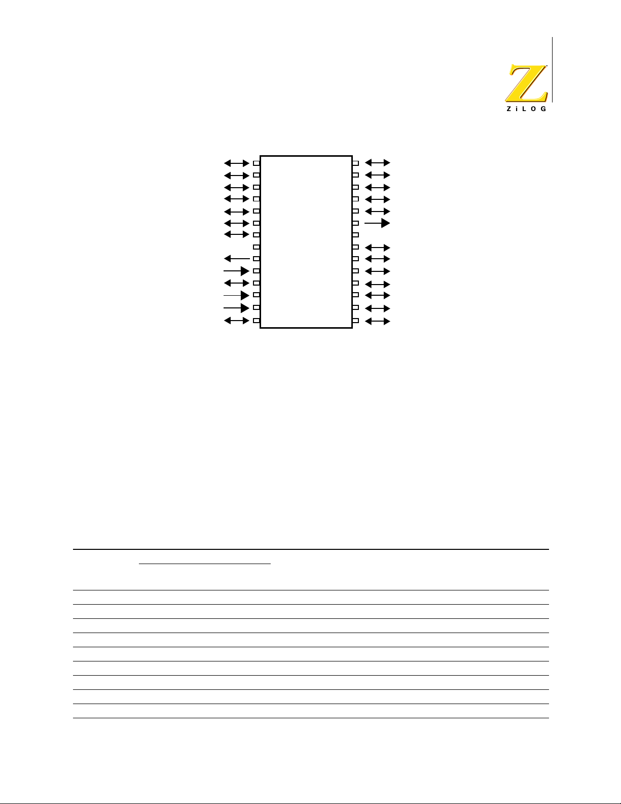
Z86D990/Z86D991 OTP and Z86L99X ROM
Low-Voltage Microcontrollers with ADC
7
P25
P26
P27
P44/ADC0
P45/ADC1
P46/ADC2
P47/ADC3
V
DD
XTAL2
XTAL1
P51/CIN1/Capture Timer Input
P52/CIN2/T1 Timer Input
P53/CREF2
P54/COUT1
1
2
3
4
Z86D991/
5
Z86L991
6
7
*
8
9
10
11
12
13
14
28
27
26
25
24
23
22
21
20
19
18
17
16
15
P24
P23
P22
P21
P20
P43/Combined T8 T16 Out put
**
V
SS
P42
P41/T16 Output
P40/T8 Out put
P50/CREF1
P56/T1 Timer Output
P57
P55/COUT2
Notes:
1. P43 is a controlled current output.
2. P54, P55, P56, and P57 are high drive
outputs.
* V
DD
= V
DD_CORE
+ V
DD_padring
+ AV
DD
Figure 4. 28-Pin SOIC/DIP Pin Assignment—User Mode
Pins Configuration
Table 2 describes the pins.
Table 2. Pin Descriptions
Pin #
28
Symbol
P20 24 34 40 I/O Port 2 Bit 0
P21 25 35 41 I/O Port 2 Bit 1
P22 26 36 44 I/O Port 2 Bit 2
P23 27 37 45 I/O Port 2 Bit 3
P24 28 38 46 I/O Port 2 Bit 4
P25 1 3 3 I/O Port 2 Bit 5
P26 2 4 4 I/O Port 2 Bit 6
P27 3 5 5 I/O Port 2 Bit 7
P40 19 29 34 I/O Port 4 Bit 0, T8 Output
PDIP/SOIC40PDIP48SSOP Direction Description
PS003807-1002 P R E L I M I N A R Y
Page 15

Z86D990/Z86D991 OTP and Z86L99X ROM
Low-Voltage Microcontrollers with ADC
Table 2. Pin Descriptions (Continued)
Pin #
28
Symbol
P41 20 30 35 I/O Port 4 Bit 1, T16 Output
P42 21 31 36 I/O Port 4 Bit 2
P43 23 33 39 Output T8/T16 Output, Controlled current output
P44 4 8 9 I/O Port 4 Bit 4, A/D Channel 0*
P45 5 9 10 I/O Port 4 Bit 5, A/D Channel 1*
P46 6 10 11 I/O Port 4 Bit 6, A/D Channel 2*
P47 7 11 12 I/O Port 4 Bit 7, A/D Channel 3*
P50, CREF1 18 28 33 I/O Port 5 Bit 0, Comparator 1 reference
P51, CIN1 11 17 20 I/O Port 5 Bit 1, Capture timer input, IRQ
P52, CIN2 12 18 21 Input Port 5 Bit 2, Timer 1 timer input, IRQ
P53, CREF2 13 19 22 Input Port 5 Bit 3, Comparator 2 reference, IRQ
P54 14 20 23 I/O Port 5 Bit 4, High drive output
P55 15 25 28 I/O Port 5 Bit 5, High drive output
P56 17 27 32 I/O Port 5 Bit 6, Timer 1 output, High drive output
P57 16 26 29 I/O Port 5 Bit 7, High drive output
P60 39 47 I/O Port 6 Bit 0
P61 40 48 I/O Port 6 Bit 1
P62 1 1 I/O Port 6 Bit 2
P63 2 2 I/O Port 6 Bit 3
P64 21 24 I/O Port 6 Bit 4
P65 22 25 I/O Port 6 Bit 5
P66 23 26 I/O Port 6 Bit 6
P67 24 27 I/O Port 6 Bit 7
XTAL1 10 16 18 Input Crystal, Oscillator clock
XTAL2 9 15 17 Output Crystal, Oscillator clock
AV
DD
V
DD_CORE
AV
SS
V
Ref–
V
Ref+
V
DD_padring
V
SS
Notes:
PDIP/SOIC40PDIP48SSOP Direction Description
2
0
1
13 14 Analog power supply
13 15 Z8 core power supply
6 7 Analog ground
7 8 Input A/D converter lower reference
12 13 Input A/D converter upper reference
8** 14 16 Power supply (pad ring)
22** 32 37, 38 Ground
*A/D converter is not available in the 28-pin configuration.
**In the 28-pin configuration, all three (core, pad ring, and analog) powers are tied together.
8
PS003807-1002 P R E L I M I N A R Y
Page 16

Operational De scription
Central Processing Unit (CPU) Description
The Z8 architecture is characterized by a flexible I/O scheme, an efficient register
and address space structure and a number of ancillary features for cost-sens itive,
high-volume embedded control applica tions. ROM-b ased pro duct s are geared for
high-volume production (where the software is stable) and one-time programmable equivalents for prototyping as well as volume production where time to market
or code flexibility is critical.
Architecture Type
The Z8 register-oriented architecture centers around an internal register file composed of 256 consecutive bytes, known as the standar d register file. The standard
register file consists of 4 I/O port registers (R2, R4, R5, and R6), 12 control and
status registers, 23 3 general-purpose registers , and 7 registers reserved for future
expansion. In addition to the standard register file, the Z86D99/Z86L99 family
uses 21 control and status registers located in the Z8 expanded register file. Any
general-purpose register can be used as an accumulator and address pointer or
an index, data, or stack regist er.
Z86D990/Z86D991 OTP and Z86L99X ROM
Low-Voltage Microcontrollers with ADC
9
All active registers can be reference d or modif ied by any instru ction t hat accesses
an 8-bit register, without the requirement for special instructions. Registers
accessed as 16 bits are tr eated as even-odd register p ai rs. In thi s case, the da ta’ s
most significant byte (MSB) is stored in the even-numbered register, while the
least significant byte (LSB) goes into th e next higher odd-numbered register.
The Z8 CPU has an instruction set designed for the l arge regi ster fil e. The inst ruc tion set provides a full compliment of 8-bit arithmetic and logical operations. BCD
operations are supported using a decimal adjustment of binary values, and 16-bit
quantities for addresses and counters can be incremented and decremented. Bit
manipulation and Rotate and Shif t instructions complete the data-manipulat ion
capabilities of the Z8 CPU. No speci al I/ O in struct ions ar e nece ssary beca use t he
I/O is mapped into the register file.
CPU Control Registers
The standard Z8 control registers gover n the operation of the CPU. Any instruction which references the register file can access these control registers. The following are available control registers:
•
Register Pointer (RP)
•
Stack Pointer (SP)
•
Program Control Flags (FLAGS)
PS003807-1002 P R E L I M I N A R Y
Page 17

Z86D990/Z86D991 OTP and Z86L99X ROM
Low-Voltage Microcontrollers with ADC
•
Interrupt Control (IPR, IMR, and IRQ)
•
Stop Mode Recovery (SMR, P2SMR, and P5SMR)
•
Low-Battery Detect (LB) Flag
The Z8 uses a 16-bit Program Counter (PC) to determine the sequence of current
program instructions. The PC is not an addressabl e regi ster.
Peripheral registers are used to transf er data, configure the operating mode, and
control the operation of the on-chip peripherals. Any instruction that references
the register file can access the peripheral registers. The following are peripheral
control registers:
•
Analog/Digital Converter (ADCCTRL and ADCDATA)
•
T1 Timer/Counter (TMR, T1, and PRE1)
10
•
T8 Timer/Counter (CTR0, HI8, LO8, TC8H, and TC8L)
•
T16 Timer/Counter (CTR2, HI16, LO16, TC16H, and TC16L)
•
T8/T16 Control Registers (CTR1and CTR3)
In addition, the four port registers are considered to be peripheral registers. The
following are port control registers:
•
Port Configuration Registers (P456CON and P3M)
•
Port 2 Control and Mode Registers (P2 and P2M)
•
Port 4 Control and Mode Registers (P4 and P4M)
•
Port 5 Control and Mode Registers (P5 and P5M)
•
Port 6 Control and Mode Registers (P6 and P6M)
The functions and applications of the control and peripheral registers are
explained in “Control and Status Registers” on page 52.
Memory (ROM/OTP and RAM)
There are four basic address spaces available to support a wide range of configurations:
•
Program memory (on-chip)
•
Standard register file
•
Expanded register file
•
Executable RAM
The Z8 standard register file totals up to 256 consecutive bytes organized as 16
groups of 16 eight-bit registers. These registers consist of I/O port registers,
PS003807-1002 P R E L I M I N A R Y
Page 18

Z86D990/Z86D991 OTP and Z86L99X ROM
Low-Voltage Microcontrollers with ADC
general-purpose RAM registers, and control and status registers. Every RAM register acts l ike an ac cumulator, speeding instruction execution and maxi mizing cod ing efficiency. Working register groups allow fast context switching.
The standard registe r file of the Z8 (known as Bank 0) has been exp anded to form
16 expanded register file (ERF) banks. The expanded register file allows for additional system control registers and for the mapping of additional peripheral
devices into the register ar ea. Eac h ERF bank can pot enti all y consist of up t o 256
registers (the same amount as in the standard register file) that can then be
divided into 16 working register group s. Currently, only Group 0 of ERF Banks F
and D (
0Fh and 0Dh) has been implemented.
In addition to the standard program memory and the RAM register files, the
Z86D99/Z86L99 family also has 256 bytes of execut able RAM that has been
mapped into the upper 256 bytes of the program memory address space (
FFFFh). Data can be written to the executable RAM by using the LDC instruction.
FF00h–
11
Program Memory Structure
The first 12 bytes of program memory are reserved for the interrupt vectors.
These locations contain six 16-bit vectors that correspond to the six available
interrupts (IRQ
through IRQ5.) Address 12 (0Ch) up to 32,767 (7FFFh) consists of
0
on-chip one-time programmable memory. The Z86L99X only has the 4K/8K/16K
ROM size.
After any reset operation (power-on reset, watch-dog timer time out, and stop
mode recovery), program execution resumes with t he ini ti a l instruction fetch from
location
000Ch. After a reset, t he fir st routin e execu ted must be one th at i niti aliz es
the control registers to the required system configuration.
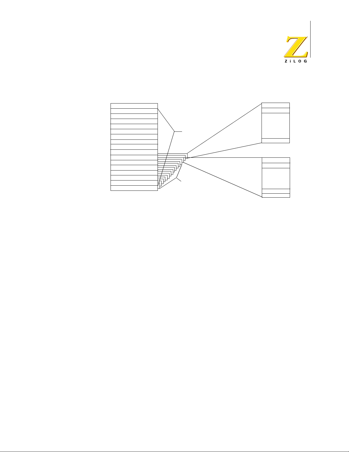
A unique feature of the Z86D99/Z86L99 family is the presence of 256 bytes of on-
chip executable RAM. This random-ac cess memo ry is in addition to the standard
Z8 register file memory available on all Z8 microcontrollers. As illustrated in
Figure 5, the executable RAM is mapped into the upper 256 bytes of the 64K program memory address space (
FF00h–FFFFh). Data can be written to the execut-
able RAM by using the LDC instruction.
Memory locations between
8000h and FEFFh have not been implemented on the
Z86D99X microcontrollers.
The Z86D99/Z86L99 family does not have the capabili ty of accessing external
memory.
PS003807-1002 P R E L I M I N A R Y
Page 19

Z86D990/Z86D991 OTP and Z86L99X ROM
Low-Voltage Microcontrollers with ADC
Location (Hex)
FFFF
256 bytes
Executable RAM
FF00
Not Implemented
3FFF/7FFF
(ROM)/(OTP) PROGRAM
MEMORY
000C Location of the first byte of the initial instruction executed after
RESET
000B IRQ
000A IRQ
0009 IRQ
0008 IRQ
0007 IRQ
0006 IRQ
0005 IRQ
0004 IRQ
0003 IRQ
0002 IRQ
0001 IRQ
0000 IRQ
Figure 5. Program Memory Map
(lower byte)
5
(upper byte)
5
(lower byte)
4
(upper byte)
4
(lower byte)
3
(upper byte)
3
(lower byte)
2
(upper byte)
2
(lower byte)
1
(upper byte)
1
(lower byte)
0
(upper byte)
0
12
Z8 Standard Regist er File (Bank 0)
Bank 0 of the Z8 expanded register file archi tecture is known as the standard register file of the Z8. As shown in Figure 6, the Z8 standard register file consists of
16 groups of sixteen 8-bit registers known as Working Register (WR) groups.
Working Register Gr oup F cont ains vari ous control and st atus registers. The lower
half of Working Register Group 0 consists of I/O port registers (R0 to R7), the
upper eight registers are available for use as general-purpose RAM registers.
Working Register Group 1 through Group E of the standard register file are available to be used as general-purpos e RAM registers. The user can use 233 bytes of
general-purpose RAM registers in the standard Z8 register file (Bank 0).
PS003807-1002 P R E L I M I N A R Y
Page 20

Z86D990/Z86D991 OTP and Z86L99X ROM
Low-Voltage Microcontrollers with ADC
Grp/Bnk Reg Working Register Group Function
(
F0h) r0 to 15 Control and Status Registers
(
E0h) r0 to 15 General-purpose RAM registe rs
D0h) r0 to 15 General-purpose RAM registers
(
(
C0h) r0 to 15 General-purpose RAM registers
(
B0h) r0 to 15 General-purpose RAM registers
A0h) r0 to 15 General-purpose RAM registe rs
(
(
90h) r0 to 15 General-purpose RAM registe rs
(
80h) r0 to 15 General-purpose RAM registers
(
70h) r0 to 15 General-purpose RAM registers
60h) r0 to 15 General-purpose RAM registe rs
(
(
50h) r0 to 15 General-purpose RAM registe rs
(
40h) r0 to 15 General-purpose RAM registe rs
30h) r0 to 15 General-purpose RAM registe rs
(
(
20h) r0 to 15 General-purpose RAM registe rs
(
10h) r0 to 15 General-purpose RAM registe rs
r8 to 15 Gener al- pur pose RAM regi ste rs
(
00h)r0 to 7I/O Port Registers
13
Figure 6. Standard Z8 Register File (Working Reg. Groups 0–F, Bank 0)
Z8 Expanded Register File
In addition to the Standard Z8 Register File (Bank 0), Expanded Register File
Banks F and D of Working Register Group 0 have been implemented on the
Z86D99/Z86L99. Figure 7 illustrates the Z8 Expanded Register File architecture.
These two expanded register file banks of Working Register Group 0 provide a
total of 32 additional RAM control and st atus registers. The Z86D99/Z86L99 family has implemented 21 of the 32 available registers.
PS003807-1002 P R E L I M I N A R Y
Page 21
Z86D990/Z86D991 OTP and Z86L99X ROM
Low-Voltage Microcontrollers with ADC
14
Z8 Standard Register File
F
Control and Status Reg.
E
D
C
B
A
Working
Register
Groups
9
8
7
6
5
4
3
2
1
0
I/O Port Registers
Bank 0
Figure 7. Z8 Expanded Register File Architecture
Clock Circuit Description
The Z8 derives its timing from on-board clock circuitry connected to pins XTAL1
and XTAL2. The clock circuitry consists of an oscillator, a divide-by-two shaping
circuit, and a clock buffer. The oscillator’s input is XTAL1, and the oscillator’s output is XTAL2. The clock can be driven by a crystal, a cer amic r esonat or, LC clock,
RC, or an external clock source.
General-Purpose
RAM Registers
Bank F
Banks 2 through C are
Reserved—Not Implemented
(Bank E is also reserved)
Z8 Expanded Register Files
Group 0, Bank F
Stop Mode
Recovery and
Port Mode
Registers
Group 0, Bank D
Timer
Control
Registers
Clock Control
The Z8 offers software control of the internal system clock using programming
register bits in the SMR register. This register selects the clock divide value and
determines the mode of STOP Mode Recovery.
The default setting is external clock divide-by-two. When bits 1 and 0 of the SMR
register are set to 0, the System Clock (SCLK) and Timer Clock (TCLK) are equal
to the external clock frequency divided by two.
When bit 1 of the SMR register is set to 1, then SCLK and TCLK equal the external clock frequency. Refer to Table 53 on page 85 for the maximum clock frequency.
A divide-by-16 prescaler of SCLK and TCLK allows the user to selectively reduce
device power consumption during normal processor execution (under SCLK control) and/or HALT mode, where TCLK sources counter/timers and interrupt logic.
Combining the divide-by-two circuitry with the divide-by-16 prescaler allows the
external clock to be divided by 32.
PS003807-1002 P R E L I M I N A R Y
Page 22

Interrupts
The Z86D99/Z86L99 family allows up to six dif ferent interrupt s, t hree external and
three internal, from nine possible sources. The six interrupts are assigned as follows:
•
•
•
•
Table 3 presents the interrupt types, the interrupt sources, and the location of the
specific interrupt vectors.
Z86D990/Z86D991 OTP and Z86L99X ROM
Low-Voltage Microcontrollers with ADC
15
Three edge-triggered external inte rrupts (P51, P52, and P53), two of which
are shared with the two analog comparators
One internal interrupt assigned to the T8 Timer
One internal interrupt assigned to the T16 Timer
One internal interrupt shared between the Low-Battery Detect flag and the T1
Timer
Table 3. Interrupt Types, Sources, and Vectors
Vector
Name Source
IRQ
0
IRQ
1
IRQ
2
IRQ
3
IRQ
4
IRQ
5
Notes:
P52 (F/R), Comparator 2 0,1 External interrupt (P52) is triggered by
P53 (F) 2,3 External interrupt (P53) is triggered by
P51 (R/F), Comparator 1 4,5 External interrupt (P51) is triggered by
T16 Timer 6,7 Internal interrupt
T8 Timer 8,9 Internal interrupt
LVD, T1 Timer 10,11 Internal interrupt, LVD flag is
F = Falling-edge triggered; R = Rising-edge triggered.
When LVD is enabled, IRQ5 is triggered only by low-voltage detection. Timer
1 does not generate an interrupt.
Location C omments
either rising or falling edge; internal
interrupt generated by Comparator 2
is mapped into IRQ
a falling edge
either a rising or falling edge; internal
interrupt generated by Comparator 1
is mapped into IRQ
multiplexed with T1 Timer End-ofCount interrupt
0
2
These interrupts can be masked and their priorities set by using the Interrupt
Mask Register (IMR) and Interrupt Priority Register (IPR) (Figure 8.) When more
than one interrupt is pending, prioriti es are resolved by a priority encoder, controlled by the IPR.
PS003807-1002 P R E L I M I N A R Y
Page 23
EI Instruction
Z86D990/Z86D991 OTP and Z86L99X ROM
Low-Voltage Microcontrollers with ADC
16
S
R
Power-On Reset
Figure 8. Interrupt Block Diagram
(POR)
Reset
Interrupt Request Register
(IRQ,FAH)
Interrupt requests are stored in the Interrupt Request Register (IRQ), which can
also be used for polling. When an interrupt request is granted, the Z8 enters an
“interrupt machine cycle” that globally disables all other interrupts, saves the program counter (the address of the next inst ruction t o be execut ed) and statu s flags,
and finally branches to the vector locati on for the interrupt granted. It is only at this
point that control passes to the interrupt service routine for the specific interrupt.
All six interrupt s can be globally disabled by resetting t he ma ster Interrupt Enable
(bit 7 of the IMR) with a Disable Interrupts (DI) instruction. Interrupts are globally
enabled by setting the same bit with an Enable Interrupts (EI) instruction.
Descriptions of three interrupt control registers—the Interrupt Request Register,
the Interrupt Mask Register, and the Interrupt Priority Register—are provided in
“Register Summary” on page 52. The Z8 family supports both vectored and polled
interrupt handling.
External Interrupt Sources
External sources involve interrupt request lines P51, P52, and P53 (IRQ
and IRQ
, respectively.) IRQ0, IRQ1, and IRQ2 are generated by a transition on
1
the corresponding port pin. As shown in Figure 9, when the appropriate port pin
(P51, P52, or P53) transitions, the firs t flip-flop is set. The next two flip-flops synchronize the request to the internal clock and del ay it by two internal clock periods. The output of the most recent flip-flop (IRQ
, IRQ1, or IRQ2) sets the
0
corresponding Interrupt Request Regi ster bit.
PS003807-1002 P R E L I M I N A R Y
, IRQ0,
2
Page 24
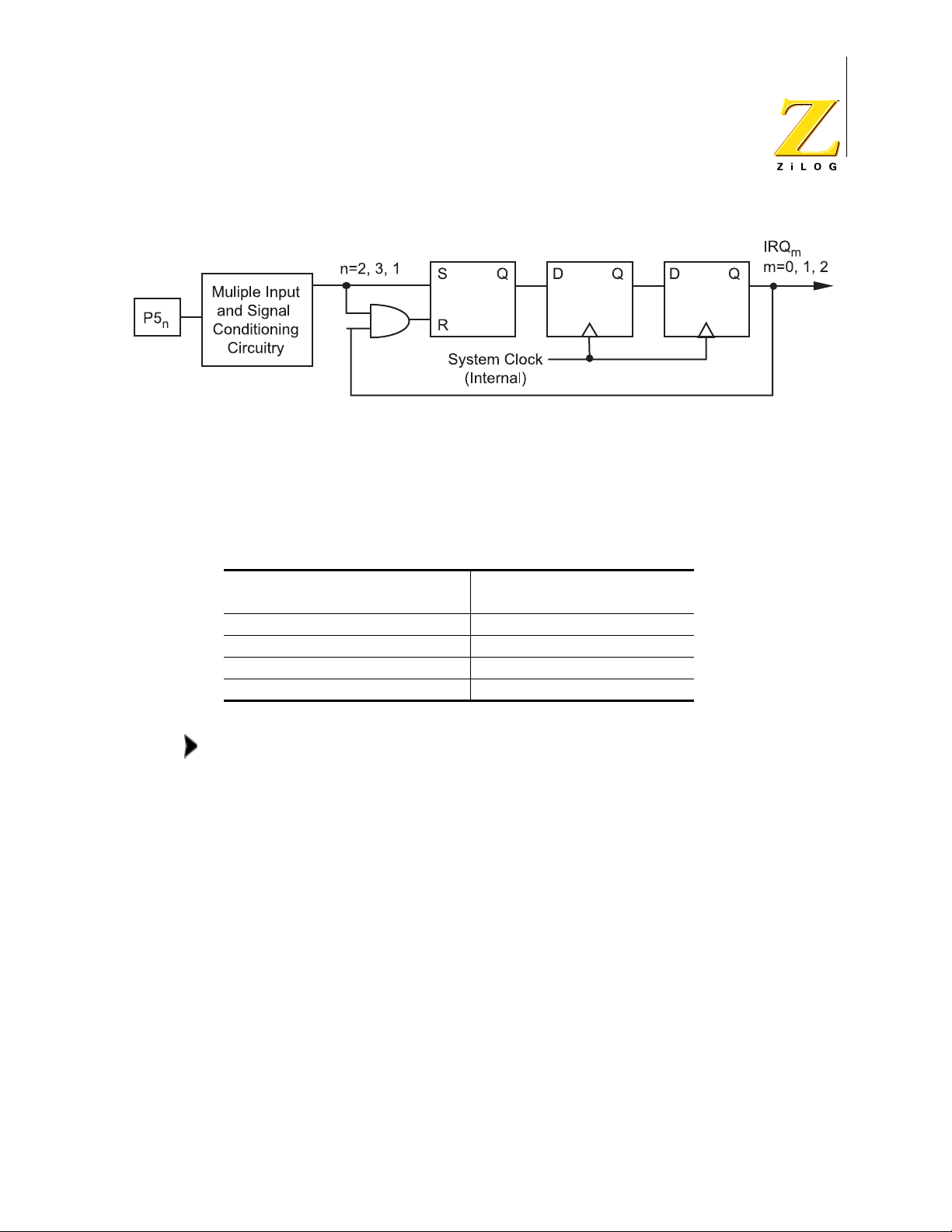
Z86D990/Z86D991 OTP and Z86L99X ROM
Low-Voltage Microcontrollers with ADC
Figure 9. External Interrupt Sources IRQ0–IRQ2 Block Diagram
The programming bits for the Int errupt Edge Select f unction are located in t he IRQ
register, bits 6 and 7. The configuration of these bits and the resulting interrupt
edge is shown in Table 4.
17
Table 4. Interrupt Edge Select for External Interrupts
Interrupt Request Register Interrupt Edge
Bit 7 Bit 6 IRQ
0 0 Falling Falling
0 1 Falling Rising
1 0 Rising Falling
1 1 Rising/Falling Rising/Falling
Note:
Although interrupts are edge tr iggered, minimum interrupt
(P51) IRQ0 (P52)
2
request Low and High times must be observed for proper
operation. See “Electrical Chara cteristi cs” on p age 85 for exact
timing requirements (T
IL, TWIH) on external interrupt
W
requests.
Internal Interrupt Sources
Internal sources are ORed with the external sources, so that either an internal or
external source can trigger the int errupt.
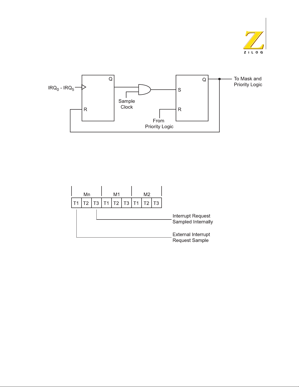
Interrupt Request Register Logic and Timing
Figure 10 shows the logic diagram for the Interrupt Request Register. The leading
edge of an interrupt request sets the first flip-flop. It remains set until the interrupt
requests are sampled.
PS003807-1002 P R E L I M I N A R Y
Page 25
Z86D990/Z86D991 OTP and Z86L99X ROM
Low-Voltage Microcontrollers with ADC
Figure 10. IRQ Logic
Internal interrupt requests are sampled during the most recent clock cycle before
an Op Code fetch (see Figure 11.) External interrupt requests are sampled two
internal clocks earlier than internal interrupt requests because of the synchronizing flip-flops shown in Fi gure 9.
18
Figure 11. Interrupt Request Timing
At sample time, the interrupt request is trans ferred to the second flip- flop shown in
Figure 10, which drives the interrupt mask and priority logic. When an interrupt
cycle occurs, this flip-flop is reset only for the highest priorit y level that is enabled.
The user has direct access to the second flip -flop by reading and writing to the
IRQ. The IRQ is read by specifying it as the source regis ter of an instruction, and
the IRQ is written by specifying it as the destination register.
Interrupt Initializatio n
After RESET, all interrupts are disabled and must be re- initia lized bef ore vecto red
or polled interrupt processing can begin. The Interrupt Priority Register, Interrupt
Mask Register, and Interrupt Request Regi ster must b e i niti alized, in that order, to
PS003807-1002 P R E L I M I N A R Y
Page 26

Z86D990/Z86D991 OTP and Z86L99X ROM
Low-Voltage Microcontrollers with ADC
start the interrupt pr ocess. However, the IPR does not have to be initialized for
polled processing.
Interrupts must be globally enabled using the EI instruction. Setting bit 7 of the
IMR is not sufficient. Subsequent to this EI instruction, interrupts can be enabled
either by IMR manipulation or by use of the EI instruction, with equivalent effects.
Additionally, interrupts must be disabled by executing a DI instruction before the
IPRs or IMRs can be modified. Interrupts can then be enabled by executing an EI
instruction.
IRQ Software I nterrupt Generatio n
IRQ can be used to generate sof tware inter rupt s by specif ying I RQ as th e dest ination of any instruction referencing the Z8 Standard Register File. These Software
Interrupts (SWIs) are controlled in the same manner as hardware-generated
requests (the IPR and the IMR control t he priority and enabl ing of each SWI level ).
19
To generate a SWI, the request bit in the IRQ is set as follows:
OR IRQ, #NUMBER
where the immediate data, NUMBER, has a 1 in the bit position corresponding to
the appropriate level of the SWI.
For example, for an SWI on IRQ5, NUMBER has a 1 in bit 5. With this i nstr uct ion,
if the interrupt system is globally enab led, IRQ5 is enabled, and there are no
higher priority pending requests, control is transferred to the service routine
pointed to by the IRQ5 vector.
Reset Conditions
A system reset overrides all other operating conditions and puts the Z8 into a
known state. The control and status registers are reset to their default condit ions
after a power-on reset (POR) or a W at ch-Dog T imer (WDT) time-out while in RUN
mode. The control and status registers are not reset to their default conditions
after Stop Mode Recovery (SMR) while in HALT or STOP mode.
General-purpose registers are undefined after the device is powered up. Resetting the Z8 does not affect the contents of the general-purpose registers. The registers keep their most recent value after any reset, as long as the reset occurs in
the specified V
from a V
Following a reset (see Table 5), the first routine executed must be one that initializes the control registers to the required system configuration.
reset, if VCC drops below V
LV
operating range. Registers do not keep their most recent state
CC
(see Table 54 on page 87).
RAM
PS003807-1002 P R E L I M I N A R Y
Page 27
Z86D990/Z86D991 OTP and Z86L99X ROM
Low-Voltage Microcontrollers with ADC
Table 5. Control and Status Register Reset Conditions
Address Reset Value
Register Function Grp/Bnk Register Symbol R/W 76543210
Register Pointer
Stack Pointer
Program Control Flags
Low Battery Detect
ADC Control
ADC Data
Interrupt Mask
Interrupt Priority
Interrupt Request
Port Configuration (A)
Port Configuration (B)
Port 2 Data
Port 2 Mode
Port 4 Data
Port 4 Mode
Port 5 Data
Port 5 Mode
Port 6 Data
Port 6 Mode
T1 Timer Data
T1 Timer Mode
T1 Timer Prescale
T8/T16 Control (A)
T8/T16 Control (B)
T8 Timer Control
T8 High Capture
T8 Low Capture
T8 High Loa d
T8 Low Load
T16 Timer Control
T16 High Capture
T16 Low Capture
T16 High Load
T16 Low Load
F0h r13 (R253) RP R/W00000000
F0h r15 (R255) SP R/WXXXXXXXX
F0h r12 (R252) Flags R/WXXXXXXXX
0Dh r12 LB R/W11111X00
0Fh r8 ADCCTRL R/W 00000000
00h r7 (R7) ADCDATA R 00000000
F0h r11 (R251) IMR R/W00000000
F0h r9 (R249) IPR W 00000000
F0h r10 (R250) IRQ R/W00000000
0Fh r0 P456CONR/W00000111
F0h r7 (R247) P3M W 11111111
00h r2 (R2) P2 R/WXXXXXXXX
F0h r6 (R246) P2M W 11111111
00h r4 (R4) P4 R/WXXXXXXXX
0Fh r2 P4M R/W11111**111
00h r5 (R5) P5 R/WXXXXXXXX
0Fh r4 P5M R/W11111111
00h r6 (R6) P6 R/WXXXXXXXX
0Fh r6 P6M R/W11111111
F0h r2 (R242) T1 R/W00000000
F0h r1 (R241) TMR R/W00000011
F0h r3 (R243) PRE1 R/W00000000
0Dh r1 CTR1 R/W000*0*0000
0Dh r3 CTR3 R/W000*XXXXX
0Dh r0 CTR0 R/W0 0 0*0*0*0*0*0
0Dh r11 HI8
0Dh r10 LO8
0Dh r5 TC8H
0Dh r4 TC8L
†
†
†
†
RW00000000
R/W00000000
R/W00000000
R/W00000000
0Dh r2 CTR2 R/W00000000
0Dh r9 HI16
0Dh r8 LO16
0Dh r7 TC16H
0Dh r6 TC16L
†
†
†
R/W00000000
R/W00000000
†
R/W00000000
R/W00000000
20
PS003807-1002 P R E L I M I N A R Y
Page 28
Z86D990/Z86D991 OTP and Z86L99X ROM
Low-Voltage Microcontrollers with ADC
Table 5. Control and Status Register Reset Conditions (Continued)
Address Reset Value
Register Function Grp/Bnk Register Symbol R/W 76543210
Stop Mode Recovery 0Fh r11 SMR R/W00100000
Port 2 SMR Source
Port 5 SMR Source
Notes:
0Fh r1 P2SMR R/W00000000
0Fh r5 P5SMR R/W00000000
†
This register is not reset following Stop Mode Recovery (SMR).
*This bit is not reset following SMR.
X means this bit is undefined at POR and is not reset following SMR.
**In OTP, the default for P43 is open-drain output at power up; you need to
initialize the P43 data. In the mask part, the P43 output is disabled until it is
configured as output.
Power-On Reset
21
A POR (cold start) always reset s the Z8 control and status registe rs to their default
conditions. A POR sets bit 7 of the Stop Mode Recovery register to 0 to indicate
that a cold start has occurred.
A timer circuit clocked by a dedicated on-board RC oscillator is used for the
Power-On Reset Timer (TPOR) function. The POR time is speci fied as T
T
time allows VCC and the oscillator circuit to st abilize before instruction exe-
POR
POR
.
cution begins.
The POR delay timer circuit is a one-shot timer triggered by one of three condi-
tions:
•
Power Fail to Power OK status including reco very from Low Voltage (V
LV)
Standby mode
•
STOP-Mode Recovery (when bit 5 of the SMR register = 1)
•
WDT time-out
Under normal operating conditions, a stop mode recovery event always triggers
the POR delay timer. This delay is necessary to allow the external oscillator time
to stabilize. When using an RC or LC oscillator (with a low Q factor), the shorter
wake-up time means the delay can be eliminated.
Bit 5 of the SMR register selects whether the POR timer delay is used after StopMode Recovery or is bypa ssed. If bit 5 =1 , then t he POR timer delay i s use d. If bit
5 = 0, then the POR timer delay is bypassed. In this cas e , the SMR source must
be held in the recovery state for 5 TpC to pass the Reset signal internally.
Watch-Dog Timer (WDT)
The WDT is a retriggerable one-shot timer that resets the Z8 if it reaches its
terminal count. When operating in the RUN modes, a WDT reset is functionally
PS003807-1002 P R E L I M I N A R Y
Page 29

equivalent to a hardware POR reset. If the mask option of the permanently
enabled watch-dog timer is selected, it runs when power up. If the option is not
selected, the WDT is initially enabled by executing the WDT instruction and
refreshed on subsequent executions of the WDT instruction.
The WDT instruction does not affect the Zero (Z), Sign (S) , and Overflow (V) flags.
Permanently enabled WDTs are always enabled, and the WDT instruction is used
to refresh it. The WDT cannot be disabled after it has been initially enabled. The
WDT is off during both HALT and STOP modes.
The WDT circuit is dri ven by an on-board RC oscillator. The time-out period for the
WDT is fixed to a typical value (see Table 57 on page 90).
Power Management
In addition to the standard RUN mode, the Z8 supports three power-down modes
to minimize device current consumption. The following three modes are supported:
Z86D990/Z86D991 OTP and Z86L99X ROM
Low-Voltage Microcontrollers with ADC
22
•
HALT
•
STOP
•
Low-Voltage Standby
Table 6 shows the status of the internal CPU clock (SCLK), the internal Timer
clock (TCLK), the external oscillator, and the Watch-Dog Timer duri ng the RUN
mode and three low-power modes.
Table 6. Clock Status in Operating Modes
Operating Mode SCLK TCLK External OSC WDT*
RUN On On On On
HALT Off On On Off
STOP Off Off Off Off
Low-Voltage Standby Off Off Off Off
Note: * When WDT is enabled by the mask option bit
Using the Power-Down Modes
In order to enter HALT or STOP mode, it is necessary to first flush the instruction
pipeline to avoid suspending execution in mid-instruction. You can flush the
PS003807-1002 P R E L I M I N A R Y
Page 30

Z86D990/Z86D991 OTP and Z86L99X ROM
Low-Voltage Microcontrollers with ADC
instruction pipeline by executing a NOP (Op Code = FFh) immediately before the
appropriate sleep instruction. For example:
Mnemonic Comment Op Code
NOP ; clear the pipeline
STOP ; enter STOP mode
FFh
6Fh
or
Mnemonic Comment Op Code
NOP ; clear the pipeline
HALT ; enter HALT mode
FFh
7Fh
23
HALT
HALT mode suspends instruction execution and turns off the internal CPU clock
(SCLK). The on-chip oscillator circuit remains active, so the internal Timer clock
(TCLK) continues to run and is applied to the counter/timers and interrupt logic.
An interrupt request, either internally or externally generated, must be executed
(enabled) to exit HALT mode. After the interrupt service routine, the program continues from the instruction immediately following the HALT.
The HAL T mode can also be exited by a POR. In thi s case, the program execution
restarts at the reset address
000Ch.
STOP
STOP mode provides the lowest possible device stan dby current. This instruction
turns off both the internal CPU clock (SCLK) and internal Timer clock (TCLK) and
reduces the standby current to the minimum.
The STOP mode is terminated by a POR or SMR source. Terminating the STOP
mode causes the processor to restart the application program at address
Note:
When the STOP instruction is execut ed, the microcontroller goes into the
000Ch.
STOP mode despite any state/change of the state of the port. The ports
need to be checked immediately before the NOP and ST OP instru ctions to
ensure the right input logic before wai ting for the change of the ports.
Stop Mode Recovery Sources
Exiting STOP mode using an SMR source is greatly simpli fied in the Z86D99/
Z86L99 family. The Z86D99/Z86L99 family of products allows 16 individual I/O
PS003807-1002 P R E L I M I N A R Y
Page 31

Z86D990/Z86D991 OTP and Z86L99X ROM
Low-Voltage Microcontrollers with ADC
pins (Ports 2 and 5) to be used as stop-mode recovery sources. The ST OP mode
is exited when one of these SMR sources is toggled. A transition from either low to
high or high to low on any pin of Port 2 or Port 5 if the pin is identified as an SMR
source will effect an SMR.
There are three registers that control STOP mode recovery:
•
Stop Mode Recovery
•
Port 2 Stop Mode Recovery (P2SMR)
•
Port 5 Stop Mode Recovery (P5SMR)
The functions and applications of these registers are explained in “Stop-Mode
Recovery Control Registers” on page 82.
Low-Voltage Standby
24
An on-chip voltage comparator checks that the V
for correct operation of the Z8. When V
(V
mode with the external oscillator stopped. If the V
RAM content is preserved.
When the power level rises above the V
functions normally.
The minimum operating voltage vari es wit h temperatu re and o perati ng frequenc y,
while V
I/O Ports
The Z86D99/Z86L99 family has up to 32 lines dedicated to input and outp ut in the
40-pin configuration. These lines are grouped into four 8-bit ports known as Port
2, Port 4, Port 5, and Port 6. Al l four port s are bi t programmable as either input s or
outputs with the exception of P52, P53, and P43. P52 and P53 are input only as
they are used in OTP programming. P43 is the controlled current output and is
therefore output only.
All ports have push-pull CMOS outputs. In addition, the push-pull outputs can be
turned off for open-drain operation using the P456CON register.
Internal resistive pull-up transi stors are available as a user-defined OTP/mask
option on all ports. For Ports 4, 5, and 6, the pull-ups are nibble selectable. For
Port 2, the pull-up option applies to all eight I /O lines.
level is at the required level
CC
falls below the low-voltage trip voltage
CC
), reset is globally driven, and then the device is put in a low-current standby
LV
varies with temperature only.
LV
remains above V
CC
level, the device performs a POR and
LV
RAM
, the
Note:
Internal pull-ups are di sabled on any given pin or group of port
pins when those pins are programmed as outputs.
PS003807-1002 P R E L I M I N A R Y
Page 32

Z86D990/Z86D991 OTP and Z86L99X ROM
Low-Voltage Microcontrollers with ADC
Mode Registers
Each port has an associated Mode Register that determines the port’s functions
and allows dynamic change in port functions during program execution. Port and
Mode Registers are mapped into the Standard Register File. Because of their
close association, Port and Mode Registers are tr eated like any other gener al-purpose register. There are no special instructions for port manipulation. Any instruction that addresses a register can address the ports. Data can be directly
accessed in the Port Register, with no extra moves.
Input and Output Registers
Each of the four ports (Port s 2, 4, 5, and 6) has an input register, a n output register, a nd as sociated buf f er and cont rol log ic. Bec ause there are sepa rat e input and
output registers associated with each port, writing bits defined as inputs store the
data in the output register. This data cannot be read as long as the bits are defined
as inputs. However, if the bits are reconfigured as output, the data stored in the
output register is reflected on the output pins and can then be read. This mechanism allows the user to initialize the outputs before driving their loads.
25
Because port inputs are async hrono us t o the Z8 i nt ernal cl ock, a READ operat ion
could occur during an input transition. In this case, the logic level might be uncertain (somewhere between a logic 1 and 0).
General Port I/O
The eight I/O lines of each port (except P43, P52, and P53) can be configured
under software control to be eit her input or output, independently. Bits programmed as outputs can be globally programmed as either push-pull or opendrain. See Figure 12.
PS003807-1002 P R E L I M I N A R Y
Page 33

Z86D990/Z86D991 OTP and Z86L99X ROM
Low-Voltage Microcontrollers with ADC
26
Open-Drain
I/O
Out
In
Figure 12. General Input/Output Pin
OTP/Mask
Option
Pull-Up
V
CC
*
Pad
Note: * Pull-up resistance is
about 200 K
75 K
Ω at 5.0 V with +50%
tolerance.
Ω at 2.3 V and
Read/Write Operations
The ports are accessed as general-purpose re gisters. Port registers are wr itten by
specifying the port register as an instructi on’s dest ination re gister . W riting t o a port
causes data to be stored in t he output regist er o f the por t, and re fl ected ext ernall y
on any bit configured as an output.
Ports are read by specifying the port register as the source register of an instruction. When an output bit is read, data on the external pin is retur ned. Under normal
loading conditions, returning data on the external pin is equivalent to reading the
output register. However , i f a bit is defi ned as an open-drain output, the data
returned is the value forced on the output pin by the external system. This value
might not be the same as the data in the output register. Reading input bits also
returns data on the external pins.
PS003807-1002 P R E L I M I N A R Y
Page 34

Z86D990/Z86D991 OTP and Z86L99X ROM
Low-Voltage Microcontrollers with ADC
Special Functions
Table 7 defines the special functions of Ports 4 and 5.
Table 7. Special Port Pin Functions
27
Function Pin Signal
Configuration Register
Analog Comparator Inputs P51 CIN1 P456CON
P52 CIN2 P456CON
Analog Comparator
References
P50 CREF1
P53 CREF2
Analog Comparator Outputs P54 COUT1
P55 COUT2
ADC Channels P44 ADC0 ADCCTRL
P45 ADC1 ADCCTRL
P46 ADC2 ADCCTRL
P47 ADC3 ADCCTRL
External Interrupts P52 IRQ
P53 IRQ
P51 IRQ
T
External Clock Input P52 T
IN
IN
0
1
2
IMR and IRQ
IMR and IRQ
IMR and IRQ
TMR and PRE1
Capture Timer Input P51 Demodulator_Input CTR1
T1 Time r Output P56 T1OUT TMR
T8 Output P40 P40_Out CTR0
T16 Output P41 P41_Out CTR2
Combined T8/T16 Output
P43 P43_Out CTR1
Controlled Current Output
ZiLOG Test Mode P41 DSn Enable P456CON
P42 ASn Enable P456CON
PS003807-1002 P R E L I M I N A R Y
Page 35

Peripherals
Analog Comparators
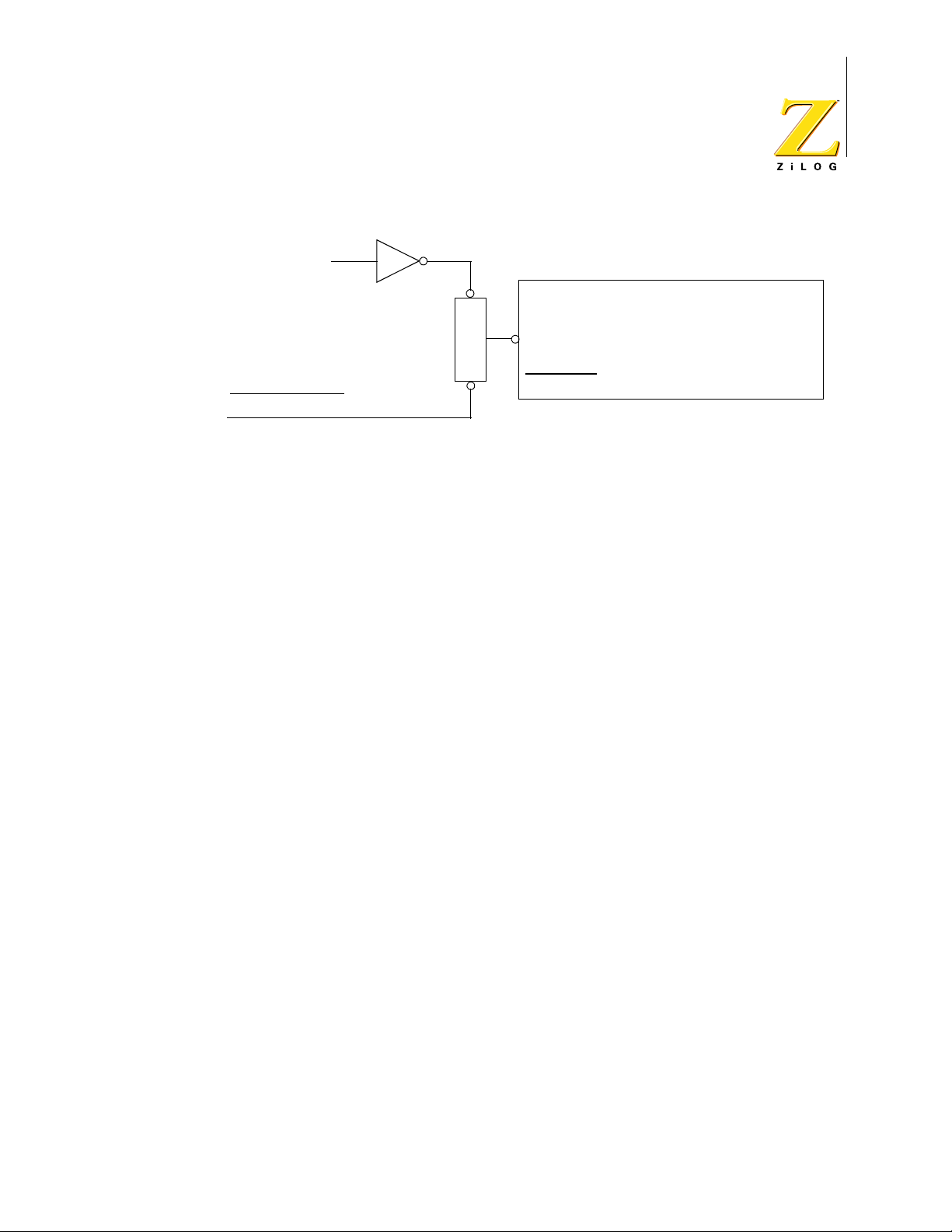
The Z86D99/Z86L99 family includes two independent on-chip general-purpose
analog comparators as shown in Figure 13. The comparators are mul tiplexed wit h
a digital input signal by the P456CON regist er. They can also be used to generate
interrupts IRQ0 and IRQ2. The comparators are turned off in STOP mode.
Z86D990/Z86D991 OTP and Z86L99X ROM
Low-Voltage Microcontrollers with ADC
28
P51
(CIN1)
P50
(CREF1)
P52
(CIN2)
P53
(CREF2)
+
–
Comparator 1
+
–
Comparator 2
P456CON
Bit5 1 = compara tor
0 = digital
P456CON
Bit4 1 = comparator
0 = digital
IRQ2, P51 Data Latch
IRQ0, P52 Data Latch
Figure 13. Analog Comparators
Analog/Digital Convert er (ADC)
The Z86D99/Z86L99 family incorporates an 8-bit ADC that uses a sigma delta
architecture (Figure 14) comprised of a modulator and a digital filter. The input is
selected (bit 3,2 from ADCCTRL) with an analog mux from 4 (P47–P44) pins that
can be configured as analog inputs (bit 7–4 from ADCCTRL).
Note:
Whenever an input pin has an analog value, the digital input
buffer has to be disabled i n or der to r educe the curr ent thr ough
the device.
PS003807-1002 P R E L I M I N A R Y
Page 36

Z86D990/Z86D991 OTP and Z86L99X ROM
Low-Voltage Microcontrollers with ADC
29
Figure 14. ADC Block Diagram
The low-pass filter transfer function is presented in Figure 15 with the –3-dB frequency given by the formula:
where f
f
3db
is the sampling frequency of the modulator.
ADC
0.0021 f
⋅=
ADC
PS003807-1002 P R E L I M I N A R Y
Page 37

0
2
4
6
8
10
Out/In[db]
12
Z86D990/Z86D991 OTP and Z86L99X ROM
Low-Voltage Microcontrollers with ADC
30
Filter response
14
16
18
20
0 0.5 1 1.5 2 2.5 3 3.5 4 4.5 5
log10(f)
Figure 15. Low-Pass Filter (with 8-MHz Crystal)
The sampling frequency of the modulator f
f
/2 (bit1 from ADCCTRL). Reducing the clock frequency lowers the power
SCLK
can be selected between f
ADC
SCLK
and
dissipated in the ADC block.
The ADC can be enabled or disabled. When enabled, the Σ∆ converter tracks the
input voltage. When switching between the channel s (step response), the
required time to reach the f inal value i s given by the time cons t an t of the l ow-p as s
filter:
T
delay
2
-------- -
f
3db
2
--------------------------- -
0.0021f
ADC
When available, the reference for the ADC i s set exte rnal ly wi th the V
952
---------- -== =
f
ADC
ref+
and V
ref-
pins. The output code represents the following ratio:
VinV
–
D
out
PS003807-1002 P R E L I M I N A R Y
------------------------------ -
V
Ref+VRef-
Ref-
–
256×=
Page 38

Z86D990/Z86D991 OTP and Z86L99X ROM
Low-Voltage Microcontrollers with ADC
31
Though the ADC functions for smal ler input volt age range (V
Ref+–VRef-
), the noise
and offsets remain constant over the specified electrical range. The errors of the
converter increase due to small input signals.
For fast access to the output of the ADC, the current data is available in the ADC
result register (r8, bank00).
To reduce the interference between the digital part and the analog p a rt, separate
and AVDD pins are available on the packages where the ADC can be used.
AV
SS
Note:
In the smaller packages, which do not support the ADC, the
user must keep the converter not active in order to not have
power dissipated in the ADC block. By default, ADC is off.
Active Glitch Filter
The Z86D99/Z86L99 family incorporates an active power/glitch filter that can be
used to improve the quality of the power supply when the device is operating in
noisy environments. The chips use three separate power buses:
•
pad ring power bus (all the output drivers plus the c rystal/RC oscillator) called
V
DD_padring
•
core power bus (all digital circuitry) called V
•
analog power bus (all analog circuitry) called AV
DD_CORE
DD
Depending on the pin availability, one or more of the power buses are connected
together.
The active power filter can be used in the packa ges that have the V
Figure 16 shows the internal schematic.
PS003807-1002 P R E L I M I N A R Y
separate.
DD
Page 39

Z86D99/Z86L99
DD_padring
V
Z86D990/Z86D991 OTP and Z86L99X ROM
Low-Voltage Microcontrollers with ADC
32
Figure 16. Active Glitch/Power Filter
When the internal power/glitch filter is not used, both V
DD_padring
and V
DD_CORE
must be connected together externally to the power supply.
When the internal circuitry is used, the V
power supply and the V
DD_CORE
has to be connected to an external energy stor-
DD_padring
has to be connected to the
age capacitor (1−10 µF range). The core is connected on ly to th is capac itor d uring
power supply glitches.
Table 8 describes the active glitch/filter specifications.
Table 8. Active Glitch/Filter Specifications (Preliminary)
Parameter Max Min Condition
Diff. stage gain 75 dB
Diff. stage bandwidth 15 MHz
Rise time 255 ns 50 mV pulse
Fall time 214 ns 50 mV pulse
R
dson
10 Ω
On the wafer level, all t hree power buses are avai lable. Depend ing on t he number
of pins of the package, one or more power buses are connected together.
The active glitch/power filter effectively increases the noise immunity for batteryoperated designs where the controller is driving high current loads (for example,
IR LED).
PS003807-1002 P R E L I M I N A R Y
Page 40

Z86D990/Z86D991 OTP and Z86L99X ROM
Low-Voltage Microcontrollers with ADC
Controlled Current Output
P43 is an open-drain output-only pin on the Z86D990/D991, but it can be config ured as output or Tristate High Impedance on the Z86L990/L991. To function
properly, Bit 3 of P4M must be set to zero to configure the pin as an open-drain
output. For the Z86L990/L991 aft er reset, P43 defaults to T rist ate High Impedance
while the Z86D990/D991 P43 is always configured as output. The data at Port 4
must be initialized as it is undefined at power-on rese t.
The current output is a contr olled curr ent sour ce that i s c ontrol led by t he output of
the value of P43 (see Table 9). P43 cannot
be configured as input, and if P43 is
read, P43 always returns the state of the output value (1 for no sink and 0 for
sink).
P43 uses internal current reference and wil l draw current if it outputs a low logic
even without external connection. This appl ies to both Run mode and Stop mode.
33
Table 9. Current Sink Pad P43 Specifications (Preliminary)
Parameter Min Max Conditions
Rise time 0.4
Fall time 0.02
V
outmin
Comparator response 0.2
Regulated current 80 mA 120 mA
Internal resistance 80
µ LED load
µ LED load
0.54 V @27C
µ
Ω
The pad driver can function in two modes:
•
controlled current output, when the voltage on the pad is over a minimum
value
V
>
padVoutmin
•
resistive pull down when the driver cannot regulate the current; in this mode,
the gate of the NMOS pull down is raised to the power rail.
The I-V characteristics of the pad are presented in Figure 17.
PS003807-1002 P R E L I M I N A R Y
Page 41

Z86D990/Z86D991 OTP and Z86L99X ROM
Low-Voltage Microcontrollers with ADC
34
Figure 17. I-V Characteristics for the Current Sink Pad P43
The CPU reads the mode of the pad driver by reading bit number 2 from the LB
register. This bit is the output of a Set-Reset flip-flop that sets whenever the voltage on the pad is lower than V
and is reset by a CPU write to the respective
outmin
register.
T1 Timer
The Z86D99/Z86L99 family provides on e general-purpose 8-bit counter/timer, T
driven by its own 6- bit presca ler , PRE
. The T1 counter/timer is in dependent of the
1
processor instruction seq uence, which relieves software from time-critical operations such as interval timing and event counting.
The T
counter/timer operates in either single-pass or continuous mode. At the
1
end-of-count, counting either stops or the initial value is reloaded and counting
continues. Under software contr ol, new values are loaded immediately or when
the end-of-count is reached. Sof tware also controls the counting mode, how the
counter/timer is star ted or stopped, and the counter/timer’s use of I/O lines. Both
the counter and prescaler registers can be altered while the counter/timer is running.
,
1
PS003807-1002 P R E L I M I N A R Y
Page 42

OSC
+2
Z86D990/Z86D991 OTP and Z86L99X ROM
Low-Voltage Microcontrollers with ADC
Counter/timer 1 is driven by a timer clock generated by dividing the internal clock
by four. The divide-by-four stage, the 6-bit prescaler, and the 8-bit counter/timer
form a synchronous 16-bit di vide chain . Counter/t imer T
external input (T
through which T
) using Port P52. Port P56 can serve as a timer output (T
IN
or the internal clock can be output. The timer output toggles at
1
can also be driven by an
1
OUT
)
the end-of-count. Figure 18 is a block diagram of the counter/timer.
35
Clock
Logic
Triggered Clock
TINP3
1
Internal
Clock
External Clock
+4
Internal Clock
Gated Clock
Figure 18. T1 Counter/Timer Block Diagram
Down Counter
Initial Value
Register
Write
6-Bit
PRE1
8-Bit
Down Counter
T1
Initial Value
Register
Write
Internal Data Bus
+2
T1
Current Value
Register
Read
T
OUT
P5
6
IRQ5
PS003807-1002 P R E L I M I N A R Y
Page 43

Z86D990/Z86D991 OTP and Z86L99X ROM
Low-Voltage Microcontrollers with ADC
The counter/timer, prescaler, and associated mode registers are mapped into the
register file as shown in Figure 19. The software uses the counter/timer as a general-purpose register, which eliminates the need for special instructions.
DEC Hex ident ifiers
243 T1 prescaler F3 PRE1
242 Timer/counter 1 F2 T1
241 Timer mode F1 TMR
36
Figure 19. Register File
Prescaler and Counter/Timer
The prescaler PRE
(F3h) consists of an 8-bit register and a 6-bit down-counter as
1
shown in Figure 18 on page 35. The prescaler register is a read-write register.
Figure 20 shows the prescaler register.
R243 PRE1
Prescaler 1 Register
F3h; Read/Write)
(
D6D5D4D3D2D1D
D
7
0
Count mode
1 = T
modulo-N
1
0 = T
single pass
1
Clock source
1 = T
internal
1
0 = T
external (TIN)
1
Prescaler modulo
(range: 1–64 decimal,
01h–00h)
Figure 20. Prescaler 1 Register
PS003807-1002 P R E L I M I N A R Y
Page 44

Z86D990/Z86D991 OTP and Z86L99X ROM
Low-Voltage Microcontrollers with ADC
The six most significant bits (D2–D7) of PRE1 hold the prescaler count modulo, a
value from 11 to 64 decimal. The prescaler register also contains control bits that
specify T
T
is internal or external.
1
The counter/timer T
counting modes. These bits also indicate whether the clock source for
1
(F2h) consists of an 8-bit down-coun ter, a write-only register
1
that holds the initial count val ue, and a read-only register that holds the current
count value (see Figure 18 on page 35). The initial value can range from 1 to 256
decimal (
01h, 02h, ..., 00h). Figure 21 illustrates the counter/timer register.
R242 T1
Counter/Timer 1 Register
F2h; Read/Write)
(
D
D6D5D4D3D2D1D
7
0
37
Figure 21. Counter/Timer 1 Register
Counter/Timer Operation
Under software control, T
(
F1h) bits D
: a Load bit and an Enable Count bit. See Figure 22.
2–D3
is started and stopped using the Timer Mode register
1
Timer Mode Register
F1h; Read/Write)
(
D
D2D1D
3
R241 TMR
0
Initial value when written
(range 1–256 decimal,
Current value when read
Reserved
0 = No function
1 = Load T
1
01h–00h)
0 = Disable T1 count
1 = Enable T
Figure 22. Timer Mode Register
PS003807-1002 P R E L I M I N A R Y
count
1
Page 45

Load and Enable Count Bits
Z86D990/Z86D991 OTP and Z86L99X ROM
Low-Voltage Microcontrollers with ADC
38
Setting the Load bit D
to 1 transfers the initial values in the prescaler and the
2
counter/timer registe rs into their respective down-count ers. The next inte rnal clock
resets bit D
to 0, readying the Load bit for the next load operation. The initial val-
2
ues can be loaded into the down-counters at any time. If the counter/timer is running, the counter/timer continues to run and starts the count over with the initial
value. Therefore, the Load bit actuall y functions as a software re-trigger.
The T
enable counting, the Enable Count bit D
counter/timer remains at rest as long as the Enable Count bit D3 is 0. To
1
must be set to 1. Counting actually start s
3
when the Enable Count bit is written by an instructi on. The first decrement occurs
four internal clock periods after the Enable Count bit has been set.
The Load and Enable Count bits can be set at the same time. For example, using
the instruction
PRE
and T1 are loaded into their respective counters, and the count is started
1
OR TMR #%0C sets both D
and D3 of TMR to 1. The initial values of
2
after the M2T2 machine state after the operand is fetched as shown in Figure 23.
M
3
T1T2T3T1T2T3T1T2T3T1T2T
M
1
M
2
M
n
3
#03 is fetched TMR is written;
counter/timers
are loaded
Figure 23. Starting the Count
first decrement
Prescaler Operations
During counting, the programmed clock source dr ives the prescaler 6-bit counter.
The counter is counted down from the value specified by bits D
sponding prescaler register, PRE
or PRE1 (Figure 24). When the prescaler
0
counter reaches its end-of- count, the initial value is reloaded and counting cont inues. The prescaler never actually reaches zero. For example, if the prescaler is
set to divide by three, the count sequence is as fol lows:
3-2-1-3-2-1-3-2...
PS003807-1002 P R E L I M I N A R Y
occurs four
clocks later
of the corre-
2–D7
Page 46

Z86D990/Z86D991 OTP and Z86L99X ROM
Low-Voltage Microcontrollers with ADC
R243 PRE1
Prescaler 1 Register
(
F3h; Read/Write)
D
0
Count mode
modulo-N
1 = T
1
0 = T
single pass
1
Figure 24. Counting Modes
When the PRE1 register is loaded with 000000 in the six most signi ficant bits, the
prescaler divides by 64. If that number is 000001, the prescaler does not divide
and passes its clock on to T
.
1
Each time the prescaler reaches its end-of -count, a carry is generated, which
allows the counter/timer to decrement by one on the next timer clock input. When
and PRE1 both reach their end-of-count, an interrupt request is generated—
T
1
IRQ
for T1. Depending on the counting mode selected, the counter/timer either
5
comes to rest with its value at
00h (single-pass mode), or th e initial value is auto-
matically reloaded and counting continues (continuous mode). In single-pass
mode, the prescaler still continues to decrement when the timer T
has reached
1
its end-of-count. The prescaler always starts from its programmed value upon
restarting the counter.
39
The counting modes are controlled by bit D
gle-pass counting mode or set to
1 for continuous mode.
of PRE1, with D0 cleared to 0 for sin-
0
The counter/timer can be stopped at any time by setting the Enable Count bit to
and restarted by setting the Enable Count bit ba ck to
1. The T
tinues its count value at the time it was stopped. The current value in the T
counter/timer can be read at any time without affecting the counting operation.
New initial values can be written to the prescal e r or the counter/timer registers at
any time. These values are transferred to their respective down-counters on the
next load operation. If the counter/timer mode is continuous, the next load occurs
on the timer clock following an end-of-count. New initial values must be written
before the load operation because the prescaler always effectively operates in
continuous count mode.
If the value loaded in the T
register is 01h, the timer is actually not timing or
1
counting at all; the timer is passing the prescaler end-of-count through. Because
the prescaler is continuously running, regardless of the single-pass/continuous
mode operation, the 8-bit timer continuously times out at the rate of the prescaler
end-of-count if the T
PS003807-1002 P R E L I M I N A R Y
timer value is programmed to 01h.
1
counter/timer con-
1
1
0
Page 47

Z86D990/Z86D991 OTP and Z86L99X ROM
Low-Voltage Microcontrollers with ADC
The time interval (i) until end-of-count, i s given by
i = t x p x v
where t is 8 divided by XTAL frequency, p is the prescaler value (1 – 64), and v is
the counter/timer value (1 – 256). The prescaler and counter/timer are true divideby-n counters.
Modes
T
OUT
The Timer Mode register TMR (
Port 5 Mode register P5M to confi gure P5
function, P5
must be defined as an output line by setting P5M bit D6 to 0. Output
6
is controlled by one of the counter/timers (T
F1h) (Figure 25) is used in conjunction with the
for T
6
or T1) or the internal clock.
0
operation. In order for T
OUT
OUT
to
R241 TMR
Timer Mode Register
F1h; Read/Write)
(
40
D7D
Figure 25. Timer Mode Register T
6
D
2
0 = No function
Operation
OUT
1 = Load T
T
OUT
T
OUT
Reserved = 01
T
out = 10
1
Internal clock out = 11
1
modes
off = 00
The P56 output is selected by TMR bits D7 and D6. T1 is selected by setting D7
and D
ting TMR bits D
T
At end-of-count, the interrupt request line IRQ
put of this flip-flop dri ves the T
reaches its end-of-count, T
example, the counter/timer is in continuous counting mode, T
to 1 and 0, respectively. The counter/timer T
6
and D6 both to 0, freeing P36 to be a data output line.
7
is initialized to a logic 1 whenever the TMR Load bit D2 is set to 1.
OUT
clocks a toggle flip-flop. The out-
5
line P56. In all cases, when the counter/timer
OUT
toggles to its opposit e state (see Figure 26). If, for
OUT
mode is turned off by set-
OUT
OUT
has a 50% duty
cycle output. You can control the duty cycle by varying the initial values after each
end-of-count.
PS003807-1002 P R E L I M I N A R Y
Page 48

IRQ5 (T1 end-of-count)
+2
Z86D990/Z86D991 OTP and Z86L99X ROM
Low-Voltage Microcontrollers with ADC
P5
6
T
OUT
41
Figure 26. Counter/Timer Output Using T
OUT
The internal clock can be selected as output instead of T1 by setting TMR bits D7
and D
P5
Figure 27. Internal Clock Output Using T
While programmed as T
However, the Z8 software can examine P5
both to 1. The internal clock (XTAL frequency/2) is then directly output on
6
(Figure 27).
6
Internal clock
OSC
TMR
TMR
+2
P5
6
OUT
, P56 cannot be modified by a write t o port reg ister P5.
OUT
’s current output by reading the port
6
T
OUT
register.
T
Modes
IN
The Timer Mode register TMR (
Prescaler register PRE
conjunction with T
•
External clock input
•
Gated internal clock
•
Triggered internal clock
•
Retriggerable internal clock
PS003807-1002 P R E L I M I N A R Y
(F3h) (Figure 29) to configure P52 as TIN. TIN is used in
1
in one of four modes:
1
F1h) (Figure 28) is used in conjunction with the
Page 49

Z86D990/Z86D991 OTP and Z86L99X ROM
Low-Voltage Microcontrollers with ADC
R241 TMR
Timer Mode Register
(
F1h; Read/Write)
42
D5D
Figure 28. Timer Mode Register TIN Operation
4
R243 PRE1
Prescaler 1 Register
(
F3h; Write Only)
D
1
TIN modes
External clock input = 00
Gate input = 01
Trigger input = 10
(non-retriggerable)
Trigger input = 11
(retriggerable)
Clock source
1 = T
internal
1
0 = T
external (TIN)
1
Figure 29. Prescaler 1 TIN Operation
The T1 counter/timer clock source must be config ured for external by setting
PRE
bit D2 to 0. The Timer Mode register bits D5 and D4 can then be used to
1
select the T
For T
to start counting as a result of a TIN input, the Enable Count bit D3 in TMR
1
must be set to
operation.
IN
1. When using T
as an external clock or a gate input, the initial
IN
values must be loaded into the down-counters by setting the Load bit D
to
1 before counting begins. Initial val ues are automatically loaded in Trigger and
Retrigger modes, so software loading is unnecessary.
Configure P5
PS003807-1002 P R E L I M I N A R Y
as an input line by setting P5M bit D2 to 1.
2
in TMR
2
Page 50

Z86D990/Z86D991 OTP and Z86L99X ROM
Low-Voltage Microcontrollers with ADC
Each High-to-Low transition on TIN generates interrupt request IRQ0, regardless
of the selected T
mode or the enabled/disabled state of T1. IRQ0 must therefore
IN
be masked or enabled according to the needs of the application.
External Clock Input Mode
43
T
IN
clock
The T
External Clock Input mode (TMR bits D5 and D4 both set to 0) supports
IN
the counting of external events, where an eve nt is consi dered to be a High-to- Low
transition on T
(see Figure 30) occurrence (single-pass mode) or on every nth
IN
occurrence (continuous mode) of that event.
TMR
D
= 00
5–D4
P5
2
Internal clock
Figure 30. External Clock Input Mode
D
D PRE1
T1 IRQ5
IRQ0
Gated Internal Clock Mode
The T
tively) measures the duration of an external event. In this mode, the T
is driven by the internal timer clock, gated by a High level on T
T
1
IRQ
gate input. Interrupt request IRQ
Gated Internal Clock mode (TMR bits D5 and D4 set to 0 and 1, respec-
IN
prescaler
1
(see Figure 31).
IN
counts while TIN is High and stops counting when TIN is Low. Interrupt request
is generated on the High-to-Low transition of TIN, signaling the end of the
0
is generated if T1 reaches its end-of-count.
5
OSC
T
IN
gate
PS003807-1002 P R E L I M I N A R Y
P5
2
Figure 31. Gated Clock Input Mode
+2
TMR
D
D
D
5–D4
= 01
Internal clock
+4
T1 PRE1
IRQ5
IRQ0
Page 51

Triggered Input Mode
Z86D990/Z86D991 OTP and Z86L99X ROM
Low-Voltage Microcontrollers with ADC
44
T
IN
trigger
The T
causes T
Triggered Input mode (TMR bits D5 and D4 set to 1 and 0, respectivel y)
IN
to start counting as the re sult of an external event (see Figure 32). T1 is
1
then loaded and clocked by the i nternal timer clock following the first High-to-Low
transition on the T
gle-pass mode, the Enable bit is reset whenever T
ther T
transitions have no effect on T1 until software sets the Enabl e Count bit
IN
again. In continuous mode, when T
resets the Enable Count bit. Interr upt request IRQ
input. Subsequent TIN transitions do not affect T1. In the sin-
IN
reaches its end-of-count. Fur-
1
is triggered, counting continues until software
1
is generated when T1 reaches
5
its end-of-count.
OSC
P5
2
+2
Edge
trigger
D
D
Internal clock
TMR
D
= 1
5
TMR
D
5–D4
= 11
+4
T1 PRE1
IRQ5
Figure 32. Trigg ered Clock Mode
Retriggerable Input Mode
The T
Retriggerable Input mode (TMR bit s D5 and D4 both set to 1) causes T1 to
IN
load and start counting on every occurrence of a High-to-Low transition on T
(see Figure 32). Interrupt request IRQ
val (determined by T
prescaler and counter/timer regist er initial values) has
1
elapsed since the last High-to-Low transition on T
is generated if the programmed time inter-
5
. In single-pass mode, the
IN
end-of-count resets the Enable Count bit. Subsequent T
cause T
In continuous mode, counting continues when T
to load and start c ounting until s of tware se t s the Ena ble Count bi t again.
1
is triggered until sof twar e res et s
1
the Enable Count bit. When enabled, each High-to-Low T
PS003807-1002 P R E L I M I N A R Y
transitions do not
IN
transition causes T1 to
IN
IRQ0
IN
Page 52

Z86D990/Z86D991 OTP and Z86L99X ROM
Low-Voltage Microcontrollers with ADC
reload and restart counting. Interrupt request IRQ5 is generated on every end-ofcount.
T8 and T16 Timer Operation
The T8 timer is a programmable 8-bit counter/timer with two 8-bit capture registers and two 8-bit load registers. The T16 timer is a programmable 16-bit counter/
timer with one 16-bit capture register pair and one 16-bit load register pair. See
Figure 33. The T8 and T16 counters/timers have two modes of operation:
•
The transmit mode is used to generate complex waveforms. There are two
submodes:
–
The normal mode can be used in single-pass or modulo-N (repeating)
mode.
–
The ping-pong mode is used when the T8 timer counts down, enables the
T16 timer that counts down, enabling T8, and so on, until the mode is
disabled.
45
•
The demodulation mode is used to capture and demodulate complex
waveforms.
PS003807-1002 P R E L I M I N A R Y
Page 53

Z86D990/Z86D991 OTP and Z86L99X ROM
Low-Voltage Microcontrollers with ADC
46
Input
Glitch
Filter
Edge
Detect
Circuit
HI16
8 8
16-Bit
T16
8
TC16H TC16L
HI8
8
8-Bit
T8
8
LO16
16
8
LO8
8
8
SCLK
1 2 4 8
Clock
Divider
T16 Clocked
And/Or
Logic
1 2 4 8
Timer 16
Timer
8/16
Timer 8
TC8H
Figure 33. Counter/Timer Architecture
TC8L
SCLK
T8 Tran smit Mode
Before T8 is enabled, the output of T8 depends on CTR1, D1. If CTR1, D1 is 0,
T8_OUT is 1. If CTR1, D1 is 1, T8_OUT is 0.
When T8 is enabled, the output T8_OUT switches to the initi al value (CTR1 D1). If
the initial value (CTR1 D1) is 0, TC8L is loaded; otherwise, TC8H is loaded into
the counter. In single-pass mode (CTR0 D6), T8 counts down to 0 and stops,
T8_OUT toggles, the time-out s t atus bi t (CTR0 D5) is set , and a ti me-out i nterr upt
can be generated if it is enabled (CTR0 D1). In modulo-N mode, upon reaching
terminal count, T8_OUT i s toggl ed, but no inte rr upt is gen erat ed. Then T8 loa ds a
new count (if T8_OUT level is 0), TC8L is loaded; if T8_OUT i s 1, TC8H is loaded.
PS003807-1002 P R E L I M I N A R Y
Clock
Divider
T8 Clock Divider
Page 54

Z86D990/Z86D991 OTP and Z86L99X ROM
Low-Voltage Microcontrollers with ADC
T8 counts down to 0, toggles T8_OUT, sets the time-out st atus bit (CTR0 D5) , and
generates an interrupt if enabled (CTR0 D1). This completes one cycle. T8 then
loads from TC8H or TC8L, according to the T8_OUT level, and repeats the cycl e.
The user can modify the values in TC8H or TC8L at any time.The new values t ake
effect when they are loaded. Do not write these reg isters at the time the values
are to be loaded into the counter/timer. An initial count of 1 is not allowed. An initial count of 0 causes TC8 to count from 0 to
FFh to FEh. Transition from 0 to FFh
is not a time-out condition (see Figure 34).
47
PS003807-1002 P R E L I M I N A R Y
Page 55

Reset T8_Enable B it
Transmit M ode
No
T8_Enable Bit Set
Z86D990/Z86D991 OTP and Z86L99X ROM
Low-Voltage Microcontrollers with ADC
48
T8 (8-Bit)
CTR0 D7
Yes
Reset T8_OUT
Set Time-out Status Bit
(CTR0 D5) and Ge nerate
Time out_Int. if Ena b led
Single Pass
Reset T8_OUT
Load TC8L
Load TC8L
0
No
Modulo-N
1
T8_OUT Value
CTR1 D1
Value
Enable T8
T8_Timeout
Yes
Single
Pass?
1
Load TC8H
Set T8_OUT
0
Load TC8H
Set T8_OUT
No
Enable T8
T8_Timeout
Yes
Disable T8
Set Time-out Status Bit
(CTR0 D5) and Generate
Time o ut_Int. if Enab le d
Figure 34. Transmit Mode Flowchart
PS003807-1002 P R E L I M I N A R Y
Page 56

Z86D990/Z86D991 OTP and Z86L99X ROM
Low-Voltage Microcontrollers with ADC
49
Note:
Do not use the same instructions for stopping the counter/
timers and setting the status bits. Two succes sive commands
are necessary—the first command for stopping counter/timers
and the second command for resetting the status bits—
because one counter/timer clock interv al must complete for the
initiated event to actually occur.
T8 Demodulation Mode
Program TC8L and TC8H to
FFh. After T8 is enabled, when the first edge (risi ng,
falling, or both, depending on CTR1 D5, D4) is detected, i t starts to count down.
When a subsequent edge (rising, falling, or both, depending on CTR1 D5, D4) is
detected during counting, the current value of T8 is one’s complemented and put
into one of the capture registers. If T8 is a positive edge, data is placed in LO8. If
T8 is a negative edge, data is placed in H18. One of the edge-detect st atus bits
(CTR1 D1, D0) is set, and an interrupt can be generated if enabled (CTR0 D2).
Meanwhile, T8 is loaded with TC8H and sta rts counti ng again. If T8 reach es 0, the
time-out status bit (CTR0 D5) is set, and an interrupt can be generated if enabled
(CTR0 D1), and T8 continues counting from
FFh (see Figure 35).
PS003807-1002 P R E L I M I N A R Y
Page 57

T8 (8-Bit)
Demodulati on Mode
T8 Enable
No
CTR0, D7
Yes
FFh→ TC8
First
Edge Present
No
Z86D990/Z86D991 OTP and Z86L99X ROM
Low-Voltage Microcontrollers with ADC
50
Disable TC8
Yes
Enable TC8
T8_Enable
No
Set Edge Present Status
Bit Set
Yes
Edge Present
Yes
Bit and Trigger Data
Capture Int. if Enabled
No
No
T8 Time Out
Yes
Set Time-out Status
Bit and Trigger Time
Out Int. if Enabled
Continue Counting
Figure 35. Demodulation Mode Flowchart
PS003807-1002 P R E L I M I N A R Y
Page 58

Z86D990/Z86D991 OTP and Z86L99X ROM
Low-Voltage Microcontrollers with ADC
T16 Transit Mode
In normal or ping-pong mode, the output of T16, when not enabled, is dependent
on CTR1, D0. If CTR1, D0 is a 0, T16_OUT is a 1; i f CTR1, D0 is a 1, T16_OUT is
0. The user can force the output of T16 to either a 0 or 1, whether it is enabled or
not, by programming CTR1 D3, D2 to a 10 or 11.
When T16 is enabled, TC16H * 256 + TC16L is loaded, and T16_OUT is switched
to its initial value ( CTR1 d0). When T16 counts down to 0, T16_OUT is toggled ( in
normal or ping-pong mode), an interrupt is genera ted if enabled (CTR2 D1), and a
status bit (CTR2 D5) is set. If it is in modulo-N mode, i t is loaded wit h TC16H * 256
+ TC16L, and the counting continues.
The user can modify the values in TC16H and TC16L at any time. The new values
take effect when they are loaded. Do not load these registers at the time the values are to be loaded into the count er/timer. An in itial count of 1 is not allowed. An
initial count of 0 causes T16 to count from 0 to
to
FFFFh is not a time-out condition.
FFFFh to FFFEh. Transition from 0
51
T16 Demodulation Mode
Program TC16L and TC16H to
FFh. After T16 is enabled, when the first edge (ris-
ing, falling, or both, depending on CTR1 D5, D4) is detected, T16 captures HI16
and LO16, reloads, and begins counting.
Ping-Pong Mode
This operation mode is only valid in transmit mode. T8 and T16 must be programmed in single-pass mode (CTR0 D6, CTR2 D6), and ping-pong mode must
be programmed in CTR1 D3, D2. The user can begin the operation by enabling
either T8 or T16 (CTR0 D7 or CTR2 D7). For example, if T8 is enabled, T8_OUT
is set to this ini ti al value (CTR1 D1). According to T8_OUT’s level, TC8H or TC8L
is loaded into T8. After the terminal count is reached, T8 is disabled, and T16 is
enabled. T16_OUT switches to its initial value (CTR1 D0), data from TC16H and
TC16L is loaded, and T16 start s to count. After T16 reaches the terminal count , it
stops. T8 is enabled agai n, and the whole cycle r epeats. In terrupts can be allowed
when T8 or T16 reaches terminal control (CTR0 D1, CTR2 D1). To stop the pingpong operation, write 00 to bits D3 and D2 or CTR1.
Note:
Enabling ping-pong operation while the counter s/timers are
running can cause intermittent counter/timer function. Disable
the counters/timers, then reset the status flags before starting
the ping-pong mode.
PS003807-1002 P R E L I M I N A R Y
Page 59

Control and Status Registers
The Z86D99/Z86L99 family has 4 I/O port registers, 33 status and control registers, and 233 general-purpose RAM registers. The I/O port and control registers
are included in the ge neral-purpos e register memory to al low any Z8 instruct ion to
process I/O or control information directly , thus eliminating the requirement for
special I/O or control instructions. The Z8 instruction set permits direct access to
any of these 37 registers. In addition, each of the 233 general-purpose registers
can also function as an accumulator, an address pointer, or an index register.
Registers identified as “Reserved” do not exist or have not been implemented in
this design.
Register Summary
Z86D990/Z86D991 OTP and Z86L99X ROM
Low-Voltage Microcontrollers with ADC
52
Table 10 through Table 13 summarize the name and location of all registers. The
register-by-register descriptions follow this section.
Table 10.I/O Port Registers (Group 0, Bank 0, Registers 0–F)
Grp/Bnk Reg Register Function Identifier
(
00h)rF General-Purpose RAM Register GPR
(
00h)rE General-Purpose RAM Register GPR
00h)rD General-Purpose RAM Register GPR
(
(
00h)rC General-Purpose RAM Register GPR
(
00h)rB General-Purpose RAM Register GPR
00h)rA General-Purpose RAM Register GPR
(
(
00h)r9 General-Purpose RAM Register GPR
(
00h)r8 General-Purpose RAM Register GPR
(00h)r7 Analog/Digital Converted Data ADCDATA
(
00h)r6 Port 6 Control Register P6
(
00h)r5 Port 5 Control Register P5
00h)r4 Port 4 Control Register P4
(
(
00h)r3 Reserved
(
00h)r2 Port 2 Control Register P2
00h)r1 Reserved
(
(
00h)r0 Reserved
PS003807-1002 P R E L I M I N A R Y
Page 60

Z86D990/Z86D991 OTP and Z86L99X ROM
Low-Voltage Microcontrollers with ADC
Table 11.Control and Status Registers (Group F, Bank 0, Registers 0–F)
Grp/Bnk Reg Register Function Identifier
F0h)rF Stack Pointer SP
(
(
F0h)rE General-purpose RAM Regis ter GPR
(
F0h)rD Register Pointer RP
F0h)rC Program Control Flag Register Flags
(
(
F0h)rB Interrupt Mask Register IMR
(
F0h)rA Interrupt Request Register IRQ
(
F0h)r9 Interrupt Priority Register IPR
F0h)r8 Reserved
(
(
F0h)r7 Port 3 Mode Register P3M
(
F0h)r6 Port 2 Mode Register P2M
F0h)r5 Reserved
(
(
F0h)r4 Reserved
(
F0h)r3 T1 Prescale Register PRE1
F0h)r2 T1 Data Register T1
(
(
F0h)r1 T1 Mode Register TMR
(
F0h)r0 Reserved
53
Table 12.Timer Control Registers (Group 0, Bank D, Registers 0–F)
Grp/Bnk Reg Register Function Identifier
(
0Dh)rF Reserved
0Dh)rE Reserved
(
(
0Dh)rD Reserved
(
0Dh)rC Low-Battery Detect Flag LB
(0Dh)rB T16 MS-Byte Capture Register HI8
(
0Dh)rA T16 LS-Byte Capture Register LO8
(
0Dh)r9 T8 High Capture Register HI16
0Dh)r8 T8 Low Capture Register LO16
(
(
0Dh)r7 T16 MS-Byte Hold Register TC16H
(
0Dh)r6 T16 LS-Byte Hold Register TC16L
0Dh)r5 T8 High Hold Register TC8H
(
(
0Dh)r4 T8 Low Hold Register TC8L
(
0Dh)r3 T8/T16 Control Register B CTR3
0Dh)r2 T16 Control Register CTR2
(
(
0Dh)r1 T8/T16 Control Register A CTR1
(
0Dh)r0 T8 Control Register CTR0
PS003807-1002 P R E L I M I N A R Y
Page 61

Z86D990/Z86D991 OTP and Z86L99X ROM
Low-Voltage Microcontrollers with ADC
Table 13.SMR and Port Mode Registers (Group 0, Bank F, Registers 0–F)
Grp/Bnk Reg Register Function Identifier
0Fh)rF Reserved
(
(
0Fh)rE Reserved
(
0Fh)rD Reserved
0Fh)rC Reserved
(
(
0Fh)rB Stop Mode Recovery Register SMR
(
0Fh)rA Reserved
(
0Fh)r9 Reserved
0Fh)r8 ADC Control Register ADCCTRL
(
(
0Fh)r7 Reserved
(
0Fh)r6 Port 6 Mode P6M
0Fh)r5 Port 5 Stop Mode Recovery P5SMR
(
(
0Fh)r4 Port 5 Mode Register P5M
(
0Fh)r3 Reserved
0Fh)r2 Port 4 Mode Register P4M
(
(
0Fh)r1 Port 2 Stop Mode Recovery P2SMR
(
0Fh)r0 Port Configuration Register P456CON
54
Register Error Conditions
Registers in the Z8 S tand ard Register File must be used corr ectly because cert ain
conditions produce inconsistent results and must be avoided.
•
Registers F5h–F9h are write-only registers. If an attempt is made to read t hese
registers,
•
When the Register Pointer (regis ter FDH) i s read, th e least si gnificant four bit s
(lower nibble) indicate the current Expanded Register File Bank. (For
example, 0000 indicates the Standard Register File, while 1010 indicates
Expanded Register File Bank A.)
•
Writing to bits that are selected as timer outputs changes the I/O register but
has no effect on the pin signal.
•
The Z8 instruction DJNZ uses any general-purpose working register as a
counter.
•
Logical instructions such as OR and AND require that the current contents of
the operand be read. They do not function properly on write-only registers.
FFh is returned. Reading any write-only register returns FFh.
PS003807-1002 P R E L I M I N A R Y
Page 62

Registers (Grouped by Function)
The following is a summary of the 37 special-purpose registers of the Z86D99/
Z86L99 family grouped by function. The following are the functional groups:
•
Flags and Pointers
•
Analog-to-Digital Converter Control
•
Interrupt Control
•
I/O Port Control
•
Timer Control—General-Purpose Timer (T1)
•
Timer Control—T8 and T16 Timers
•
Stop-Mode Recovery Control
Z86D990/Z86D991 OTP and Z86L99X ROM
Low-Voltage Microcontrollers with ADC
55
For any of the registers described in this section (see Table 14), bits identified as
“Reserved” either do not exist (meaning they have not been implemented in this
design) or have a special purpose in a ZiLOG engineering or test environment.
Caution:
Do not attempt to use these bits as the results are
unpredictable and meaningless.
T able 14.Register Description Locations
Address
Grp/Bnk Register Register Function Symbol Location
00h r2 (R2) Port 2 Data P2 page 68
00h r4 (R4) Port 4 Data P4 page 69
00h r5 (R5) Port 5 Data P5 page 70
00h r6 (R6) Port 6 Data P6 page 71
00h r7 (R7) ADC Data ADCDATA page 62
0Dh r0 T8 Timer Control CTR0 page 77
0Dh r1 T8/T16 Control (A) CTR1 page 74
0Dh r2 T16 Timer Control CTR2 page 80
0Dh r3 T8/T16 Control (B) CTR3 page 76
0Dh r4 T 8 Low Load TC8L
0Dh r5 T 8 Hig h Load T C8 H
0Dh r6 T16 Low Load TC16L
0Dh r7 T16 High Load TC16H
0Dh r8 T16 Low Capture LO16
0Dh r9 T16 High Capture HI16
0Dh r10 T8 Low Capture LO8
†
†
†
†
†
†
page 79
page 79
page 82
†
page 82
page 81
page 81
page 78
PS003807-1002 P R E L I M I N A R Y
Page 63

Z86D990/Z86D991 OTP and Z86L99X ROM
Low-Voltage Microcontrollers with ADC
Table 14.Register Description Locations (Continued)
Address
Grp/Bnk Register Register Function Symbol Location
0Dh r11 T8 High Capture HI8
0Dh r12 Low Battery Detect LB page 60
0Fh r0 Port Configuration (A) P456CON page 67
0Fh r1 Port 2 SMR Source P2SMR page 84
0Fh r2 Port 4 Mode P4M page 69
0Fh r4 Port 5 Mode P5M page 70
0Fh r5 Port 5 SMR Source P5SMR page 84
0Fh r6 Port 6 Mode P6M page 71
0Fh r8 ADC Control ADCCTRL page 61
0Fh r11 Stop Mode Recovery SMR page 83
F0h r1 (R241) T1 Timer Mode TMR page 72
F0h r2 (R242) T1 Timer Data T1 page 72
F0h r3 (R243) T1 Timer Presca le PRE1 pa ge 73
F0h r6 (R246) Port 2 Mode P2M page 68
F0h r7 (R247) Port Configuration (B) P3M page 67
F0h r9 (R249) Interrupt Prio rity IPR page 64
F0h r10 (R250) Interr upt Requ est IRQ page 65
F0h r11 (R251) Interrupt Mask IMR page 63
F0h r12 (R252) Program Control Flags Flags page 57
F0h r13 (R253) Register Pointer RP page 58
F0h r15 (R255) St ac k Pointer SP pa ge 59
†
Note:
This register is not reset following Stop Mode Recovery
(SMR).
†
page 78
56
Flags and Pointer Registers
In addition to the three standard Z8 flag and pointer registers (Program Control
Register Pointer, and Stack Pointer), the Z86D99/Z86L99 family includes a LowBattery Detect Flag register.
PS003807-1002 P R E L I M I N A R Y
Page 64

Z86D990/Z86D991 OTP and Z86L99X ROM
Low-Voltage Microcontrollers with ADC
Program Control Flag Register (Flags)
The Program Control Flag register (see Table 15) reflects the current status of the
Z8 as shown in Table 15. The FLAGS register contains six bits of status information that are set or clear ed by CPU operations. Four of the bit s (C, V, Z, and S) can
be tested for use wi th condition al jump in structio ns. T w o flags (H and D) cannot b e
tested and are used for BCD arithmetic. The two remaining flags in the register
(F1 and F2) are available to the user, but they must be set or cleared by instructions and are not usable with conditional jumps.
Table 15.FLAGS Register [Group/Bank F0h, Register C (R252)]
Bit 76543210
Bit/FieldCZSVDHF2F1
R/W R/W R/W R/W R/W R/W R/W R/W R/W
Reset XXXXXXXX
R = Read, W = Write, X = Indeterminate
Bit
Position Bit/Field R/W Value Description
7_______ Carry Flag (C) R/W 1 Indicates the “carry out” of bit 7
position of a register being used as
an accumulator; on Rotate and Shift
instructions this bit contains the most
recent value shifted out of the
specified register
_6______ Zero Flag (Z) R/W 1 Indicates that the contents of an
accumulator register is zero following
an arithmetic or logical operation
__5_____ Sign Flag (S) R/W X Stores the value of the most
significant bit of a result following an
arithmetic, logical, Rotate, or Shift
operation; in arithmetic operations on
signed numbers, a positive number is
identified by a 0, and a negative
number is identified by a 1
___4____ Overflow
Flag (V)
R/W 1 For signed arithmetic, Rotate, and
Shift operations, the flag is set to 1
when the result is greater than the
maximum possible number (>127) or
less than the minimum possible
number (<-128) that can be
represented in two’s complement
form; following logical operations, this
flag is set to 0
57
PS003807-1002 P R E L I M I N A R Y
Page 65

Z86D990/Z86D991 OTP and Z86L99X ROM
Low-Voltage Microcontrollers with ADC
Table 15.FLAGS Register [Group/Bank F0h, Register C (R252)] (Continued)
58
____3___ Decimal Adjust
Flag (D)
_____2__ Half Carry
Flag (H)
______1_ User Flag (F2) R/W 1
_______0 User Flag (F1) R/W 1
R/W 1
R/W 1
Used for BCD arithmetic—after a
0
0
0
0
subtraction, the flag is set to 1;
following an addition, it is cleared to 0
Set to 1, whenever an addition
generates a “carry out” of bit position
3 (overflow) of an accumulator; or
subtraction generates a “borrow into”
bit 3
User definable
User definable
Register Pointer (RP)
Z8 instructions can access registers directly or indirectly using either a 4-bit or 8bit address field. The upper nibble of the Register Pointer, as described in
Table 16, contains the base address of the active Working Register GROUP. The
lower nibble contains the base address of the Expanded Register File BANK.
When using 4-bit addressing, the 4-bit addr ess of the worki ng regis ter (r0 to rF) is
combined with the upper nibble of the Register Pointer (identifying the WR
GROUP), thus forming the 8-bit actual address.
Table 16.RP Register [Group/Bank F0h, Register D (R253)]
Bit 76543210
Bit/Field Working Register Group Expanded Register File Bank
R/W R/W R/W R/W R/W R/W R/W R/W R/W
Reset 00000000
R = Read, W = Write, X = Indeterminate
Bit
Position Bit/Field R/W Value Description
7654_____ Working Register
Group Pointer
_____3210 Expanded
Register File
Bank Pointer
PS003807-1002 P R E L I M I N A R Y
R/W X Identifies 1 of 16 possible WR
Groups, each containing 16 Working
Registers
R/W X Identifies 1 of 16 possible ERF
Banks; only Banks 0, D, and F are
valid for the Z86D99/Z86L99 family
Page 66

Z86D990/Z86D991 OTP and Z86L99X ROM
Low-Voltage Microcontrollers with ADC
Stack Point er (SP)
The Z86D99/Z86L99 family of products is configured for an internal stack. The
size of the stack is l imited on ly by the avail able memory space or general -purpose
RAM registers dedicated to this task. An 8-bit stack pointer, as described in
Table 17, is used for all stack operations.
Table 17.SP Register [Group/Bank F0h, Register F (R255)]
Bit 76543210
Bit/Field Stack Pointer
R/W R/W R/W R/W R/W R/W R/W R/W R/W
Reset XXXXXXXX
R = Read, W = Write, X = Indeterminate
Bit
Position Bit/Field R/W Value Description
76543210 Stack Pointer R/W X Points to the data stored on the top of
the stack; an overflow or underflow
can occur if the stack address is
incremented or decremented during
normal stack operations
59
PS003807-1002 P R E L I M I N A R Y
Page 67

Z86D990/Z86D991 OTP and Z86L99X ROM
Low-Voltage Microcontrollers with ADC
Low-Battery Detect Flag (LB)
When the Z86D99/Z86L99 is used in a battery-operated application, one of the
on-chip comparators can be used t o check t hat the V
correct operation of the device. When voltage begins to approach the V
is at the required level for
CC
point,
BO
an on-chip low-battery detection circuit is tripped, which in turn sets a user-readable flag. The LB register, as described in Table 18, is used to set and reset the
LB flag.
Table 18.LB Register (Group/Bank 0Dh, Register C)
Bit 76543210
Pad
Bit/Field Reserved
R/W WWWWWR/WR/WR/W
Reset 11111X00
R = Read, W = Write, X = Indeterminate
Bit
Position Bit/Field R/W Value Description
76543___ Reserved R
W
_____2__ Pad LVD R
R
W
______1_ LVD_Flag R
R
W
_______0 LVD_Enable R/W 1
Note: * When LVD is enabled, IRQ5 is set only for low-voltage detection. Timer 1 will not generate
an interrupt request.
1
X
1
0
X
1
0
X
0
Always reads
No Effect
Pad is not regulated when P43=0
(V
pad<Vmin
Pad is regulating the current when
P43=0 (V
Reset Pad LB flag
LB Flag Set if
LB Flag Reset
No Effect
Enable LB *
Disable LB
LVD
; see page 33)
pad>Vmin
LVD_
Flag
11111
; see page 33)
V
DD<VLV
LVD_
Enable
60
Note:
The LB flag will be valid after enabling the detection for 20 µS
(design estimation, not tested in product ion). LB does not work
at STOP mode. It must be disabled dur ing STOP mode i n order
to reduce current.
PS003807-1002 P R E L I M I N A R Y
Page 68

Z86D990/Z86D991 OTP and Z86L99X ROM
Low-Voltage Microcontrollers with ADC
Analog-to-Digit al Converter Control Registers
The Z86D99/Z86L99 family features an 8-bit analog-to-digital converter with
external voltage references. The output of the ADC is stored in the ADC Data
Register, as shown in Table 20. The ADC is configured using the ADC Control
Register, as shown in Table 19.
Table 19.ADCCTRL Register (Group/Bank 0Fh, Register 8)
Bit 76543210
ADC
P47_
Bit/Field
R/W R/W R/W R/W R/W R/W R/W R/W R/W
Reset 00000000
R = Read, W = Write, X = Indeterminate
Bit
Position Bit/Field R/W Value Description
7_______ P47_A/D R/W 1
_6______ P46_A/D R/W 1
__5_____ P45_A/D R/W 1
___4____ P44_A/D R/W 1
____32__ Channel
______1_ A/D_PowerON R/W 1
_______0 ADC Clock Select R/W 1
A/D
Selection
P46_
A/D
P45_
A/D
R/W 11
P44_
A/D
0
0
0
0
10
01
00
0
0
Channel
Selection
P47 configured as A/D Input
P47 configured as digital input
P46 configured as A/D Input
P46 configured as digital input
P45 configured as A/D Input
P45 configured as digital input
P44 configured as A/D Input
P44 configured as digital input
Channel 3 (P47)
Channel 2 (P46)
Channel 1 (P45)
Channel 0 (P44)
ON
OFF
SCLK/2
SCLK
A/D Pwr
On
Clock
Select
61
ADC Control Register (ADCCTRL)
The ADCCTRL register controls the operation of the analog-to-digital converter.
Bits 2 and 3 of the ADCCTRL register determine which of the four analog input
channels feeds into the ADC at any given time. Bits 4 through 7 enable or dis able
the digital input buffer. When configured as an ADC input channel, the port has to
be configured in Input Mode and with the digital input bu ffer disabled.
PS003807-1002 P R E L I M I N A R Y
Page 69

Z86D990/Z86D991 OTP and Z86L99X ROM
Low-Voltage Microcontrollers with ADC
ADC Data Register (ADCDATA)
The ADCDAT A register is a read-only register that contains the digital output of
the analog-to-digital converter. See Table 20.
)
Table 20.ADCDA TA Register (Group/Bank 00h, Register 7)
Bit 76543210
Bit/Field ADC Data
R/W RRRRRRRR
Reset 00000000
R = Read, W = Write, X = Indeterminate
Bit
Position Bit/Field R/W Value Description
76543210 ADC Data R
W
Data
X
Output of the ADC
No Effect
62
Interrupt Control Registers
The Z8 allows up to six different interrupts from a variety of sources. These interrupts can be masked and their priorities set by using the Interrupt Mask Register
and Interrupt Priority Register. The Interrupt Request Register stores the interr upt
requests for both vectored and polled interrupts.
PS003807-1002 P R E L I M I N A R Y
Page 70

Z86D990/Z86D991 OTP and Z86L99X ROM
Low-Voltage Microcontrollers with ADC
Interrupt Mask Register
The IMR, as described in Table 21, individually or globally enables the six int errupt
requests. Bit 7 of the IMR is the master enable and must be set before any of the
individual interrupt request s can be recogni zed. Bit 7 must be set and reset by the
enable interrupts and disable int errupts i nstructions only. The IMR is automatically
reset during an interrupt service routine and set following the execution of an
Interrupt Return (IRET) instruction.
Table 21.IMR (Group/Bank 0Fh, Register B)
Bit 76543210
Re-
Bit/Field Master
R/W R/W R/W R/W R/W R/W R/W R/W R/W
Reset 00000000
R = Read, W = Write, X = Indeterminate
Bit
Position Bit/Field R/W Value Description
7_______ Master R/W 1
_6______ Reserved R
__5_____ IRQ
___4____ IRQ
____3___ IRQ
_____2__ IRQ
______1_ IRQ
_______0 IRQ
served IRQ5 IRQ4 IRQ3 IRQ2 IRQ1 IRQ0
Enable Master Interrupt
0
1
W
5
R/W 1
X
0
4
R/W 1
0
3
R/W 1
0
2
R/W 1
0
1
R/W 1
0
0
R/W 1
0
Disable Master Interrupt
Always reads
1
No Effect
Enable IRQ
Disable IRQ
Enable IRQ
Disable IRQ
Enable IRQ
Disable IRQ
Enable IRQ
Disable IRQ
Enable IRQ
Disable IRQ
Enable IRQ
Disable IRQ
5
5
4
4
3
3
2
2
1
1
0
0
63
Note:
Bit 7 must be reset by the DI instruction before the contents of
the Interrupt Mask Register or the Interrupt Priority Register are
changed except in the following situations:
–
Immediately after a hardware reset
–
Immediately after executing an interrupt s ervice routine and before IMR bi t
7 has been set by any instruction
PS003807-1002 P R E L I M I N A R Y
Page 71

Z86D990/Z86D991 OTP and Z86L99X ROM
Low-Voltage Microcontrollers with ADC
Interrupt Priority Register (IPR)
The IPR, as described in Table 22, is a write-only register that sets priorities for
the vectored interrupts in order to resolve simultaneous interrupt requests. There
are 48 sequence possibilities for interrupts. The six interrupts, IRQ
to IRQ5, are
0
divided into three groups of two interrupt requests each, as follows:
•
Group A consists of IRQ3 and IRQ
•
Group B consists of IRQ0 and IRQ
•
Group C consists of IRQ1 and IRQ
)
Table 22.IPR (Group/Bank 0Fh, Register 9)
Bit 76543210
Grp A
Bit/Field Reserved
R/W WWWWWWWW
Reset 00000000
R = Read, W = Write, X = Indeterminate
Bit
Position Bit/Field R/W Value Description
76______ Reserved W X No Effect
__5_____ Grp A Priority:
IRQ
and IRQ
3
___43__0 Interrupt Group
Priority
_____2__ Grp B Priority:
IRQ
and IRQ
0
______1_ Grp C Priority:
IRQ
and IRQ
1
IRQ3_5 Int_Group
W10IRQ3>IRQ5 (Group A)
5
W 111
W10IRQ0>IRQ2 (Group B)
2
W10IRQ4>IRQ1 (Group C)
4
5
2
4
110
101
100
011
010
001
000
IRQ
>IRQ3
5
Reserved
B>A>C
C>B>A
B>C>A
A>C>B
A>B>C
C>A>B
Reserved
IRQ
>IRQ0
2
IRQ
>IRQ4
1
Grp B
IRQ0_2
Grp C
IRQ1_4
Int_
Group
64
Priorities can be set both within and between groups using the IPR. Bits 1, 2, and
5 of the IPR define the priority of individual member s within the groups. Bits 0, 3,
and 4 are encoded to define six priority orders between the t h ree groups. Bits 6
and 7 are reserved.
PS003807-1002 P R E L I M I N A R Y
Page 72

Z86D990/Z86D991 OTP and Z86L99X ROM
Low-Voltage Microcontrollers with ADC
Interrupt Request Register
The IRQ, as described in Table 23, is a read/write register that stores the i nt errupt
requests for both vectored and polled interrupts. When an interrupt request is
made by any of the six interrupts, the corresponding bit in the IRQ is set to 1.
Table 23.IRQ (Group/Bank 0Fh, Register A)
Bit 76543210
Set
Bit/Field Interrupt Edge
IRQ5
R/W R/W R/W R/W R/W R/W R/W R/W R/W
Reset 00000000
R = Read, W = Write, X = Indeterminate
Bit
Position Bit/Field R/W Value Description
76______ Interrupt Edge
R/W 11
Trigger
__5_____ Set IRQ
5
R
R
W
W
___4____ Set IRQ
4
R
R
W
W
____3___ Set IRQ
3
R
R
W
W
_____2__ Set IRQ
2
R
R
W
W
______1_ Set IRQ
1
R
R
W
W
_______0 Set IRQ
0
R
R
W
W
Set
IRQ4
10
01
00
1
0
1
0
1
0
1
0
1
0
1
0
1
0
1
0
1
0
1
0
1
0
1
0
Set
IRQ3
Set
IRQ2
Set
IRQ1
Set
IRQ0
P51 Rise/FallingP52 Rise/Falling
P51 Rising P52 Falling
P51 FallingP52 Rising
P51 FallingP52 Falling
IRQ
Inactive
5
IRQ
Active
5
Set IRQ
Reset IRQ
IRQ
IRQ
Set IRQ
Reset IRQ
IRQ
IRQ
Set IRQ
Reset IRQ
IRQ
IRQ
Set IRQ
Reset IRQ
IRQ
IRQ
Set IRQ
Reset IRQ
IRQ
IRQ
Set IRQ
Reset IRQ
5
Inactive
4
Active
4
4
Inactive
3
Active
3
3
Inactive
2
Active
2
2
Inactive
1
Active
1
1
Inactive
0
Active
0
0
5
4
3
2
1
0
65
PS003807-1002 P R E L I M I N A R Y
Page 73

Z86D990/Z86D991 OTP and Z86L99X ROM
Low-Voltage Microcontrollers with ADC
Whenever a power-on reset is executed, the IRQ is reset to 00h and disabled.
Before the IRQ accept s requests, it must be enabled by execut ing an enable int errupts instruction.
66
Note:
IRQ is always cleared to
00h and is in read-only mode until the
first EI instruction that enables the IRQ to be read/write. Setting
the Global Interrupt Enable bit in the Interrupt Mask Register
(IMR bit 7) does not enable the IRQ. Execution of an EI
instruction is required.
For polled processing, IRQ must be init ialized by an EI instruction. To properly initialize the IRQ, the following code is provided:
CLR IMR ; make sure vectored interrupts are disabled
EI ; enable IRQ, otherwise it is read only
; not necessary, if interrupts were previously
; enabled
DI ; disable interrupt handling
IMR is cleared before the IRQ enabling sequence to ensure no unexpected interrupts occur when EI is executed. This code sequence must be executed before
programming the application required value s for IPR and IMR.
I/O Port Control Registers
Each of the four ports (Port s 2, 4, 5, and 6) has an input register, a n output register , and an associated buffer and control logic. Because there are separate input
and output registers associated with each port, writing bits defined as inputs
stores the data in th e output register. This data cannot be read as l ong as the bits
are defined as inputs. However, if the bits are reconfigured as output, the data
stored in the output register is reflected on the output pins and can then be read.
This mechanism allows the user to initialize the outputs before driving their loads.
PS003807-1002 P R E L I M I N A R Y
Page 74

Z86D990/Z86D991 OTP and Z86L99X ROM
Low-Voltage Microcontrollers with ADC
Port Configuration Registers (P456CON and P3M)
The port configuration register (described in Table 24) switches the comparator
inputs from digital to analog and allows Ports 4, 5, and/or 6 to be switched from
push/pull active outputs to open drain outputs. In ZiLOG Test Mode, bit 3 of this
register is used to enable the Add ress Strobe/Data Strobe. Bi t 3 is not a vail able i n
User Mode.
Table 24.P456CON Register (Group/Bank 0Fh, Register 0)
Bit 76543 210
P51_
Bit/Field Not Used
Mode
R/W R/W R/W R/W R/W R/W W W W
Reset
00000 1 1
R = Read, W = Write, X = Indeterminate
Bit
Position Bit/Field R/W Value Description
76______ Not Used R/W These bits exist but do not have any
__5_____ Comparator 1
R/W 1
Mode
___4____ Comparator 2
R/W 1
Mode
____3___ Reserved
_____2__ Port 6 Output
W10Push-Pull Active
Configuration
______1_ Port 5 Output
W10Push-Pull Active
Configuration
_______0 Port 4 Output
W10Push-Pull Active
Configuration
Note: *Do not use the read-modify-write instructions (for example, OR and AND) with this register.
Bits 0, 1, and 2 always read back 1.
†
Note:
For Z86L990/L991, P43 can never be configured as push-pull. After any reset, P43 is
configured as tristate high impedance.
P52_
Mode Reserved
function assigned to them; they are
reserved for future extensions and must
not be used.
Analog (P50, P51 as Inputs)
0
Digital inputs
Analog comparator inputs (P52, P53
0
configured as Inputs)
Digital inputs
Open Drain Outputs
Always reads back
Open Drain Outputs
Always reads back
Open Drain Outputs
Always reads back
P6_
Output
P5_
Output
1*
1*
†
1*
P4_
Output
†
1
67
Port 2 outputs are configured using the P3M Register, shown in Table 25. Bit 0 of
the P3M Register switches Port 2 from push/pull active to open drain outputs. No
other bits in this register are implemented.
PS003807-1002 P R E L I M I N A R Y
Page 75

Z86D990/Z86D991 OTP and Z86L99X ROM
Low-Voltage Microcontrollers with ADC
Table 25.P3M Register [Group/Bank F0h, Register 7 (R247)]
Bit 76543210
P2_
Bit/Field Reserved
R/W WWWWWWWW
Reset 11111111
R = Read, W = Write, X = Indeterminate
Bit
Position Bit/Field R/W Value Description
7654321_ Reserved R
_________0 Port 2 Output
Configuration
W
W10Push-Pull Active
1
X
Always reads
No Effect
Open Drain Outputs
1111111
Output
68
Port 2 Control and Mode Registers (P2 and P2M)
Port 2 is a general-purpose 8-bit, bidir e ctional I/O port, as shown in Table 26.
Each of the eight Port 2 I/O lines can be independently programmed as either
input or output using the Port 2 Mode Register (see Table 27.)
Table 26.P2 Register [Group/Bank 00h, Register 2 (R2)]
Bit 76543210
Bit/Field Port 2 Data
R/W R/W R/W R/W R/W R/W R/W R/W R/W
Reset XXXXXXXX
R = Read, W = Write, X = Indeterminate
Bit
Position Bit/Field R/W Value Description
76543210 Port 2 Data R/W Data Port 2 Input/Output Register
Table 27.P2M Register [Group/Bank F0h, Register 6 (R246)]
Bit 76543210
Bit/Field P27M P26M P25M P24M P23M P22M P21M P20M
R/W WWWWWWWW
Reset 11111111
R = Read, W = Write, X = Indeterminate
Bit
Position Bit/Field R/W Value Description
76543210
(by bit)
Port 2 Mode
Select
R
W
W
1
1
0
Always reads
Input
Output
11111111
PS003807-1002 P R E L I M I N A R Y
Page 76

Z86D990/Z86D991 OTP and Z86L99X ROM
Low-Voltage Microcontrollers with ADC
A bit set to 1 in the P2M Register configures the corresponding bit in Po rt 2 as an
input, while a bit set to 0 configures an output li ne.
Port 4 Control and Mode Registers (P4 and P4M)
Port 4 is a general-purpose 8-bit, bidir e ctional I/O port, as shown in Table 28.
Each of the eight Port 4 I/O lines can be independently programmed as either
input or output using the Port 4 Mode Register (see Table 29.)
Table 28.P4 Register [Group/Bank 00h, Register 4 (R4)]
Bit 76543210
Bit/Field Port 4 Data
R/W R/W R/W R/W R/W R/W R/W R/W R/W
Reset XXXXXXXX
R = Read, W = Write, X = Indeterminate
Bit
Position Bit/Field R/W Value Description
76543210 Port 4 Data R/W Data Port 4 Input/Output Register
69
.
Table 29.P4M Register (Group/Bank 0Fh, Register 2)
Bit 76543210
Bit/Field P47M P46M P45M P44M P43M P42M P41M P40M
R/W R/W R/W R/W R/W R/W R/W R/W R/W
Reset 11111111
R = Read, W = Write, X = Indeterminate
Bit
Position Bit/Field R/W Value Description
7654_210
(by bit)
____3___ P43
Port 4 Mode
Select
Mode Select
R/W 1
R/W 0
Input
0
1
Output
Output
Tristate High Impedance (available
on Z86L990/L991 only)
A bit set to 1 in the P4M Register configures the corresponding bit in Po rt 4 as an
input, while a bit set to 0 configures an output li ne.
Note:
P43, the controlled current output pad , cannot be configur ed as
an input. (P43 read = P43 out)
PS003807-1002 P R E L I M I N A R Y
Page 77

Z86D990/Z86D991 OTP and Z86L99X ROM
Low-Voltage Microcontrollers with ADC
Port 5 Control and Mode Registers (P5 and P5M)
Port 5 is a general-purpose 8-bit, bidir e ctional I/O port, as shown in Table 30.
Each of the eight Port 5 I/O lines can be independently programmed as either
input or output using the Port 5 Mode Register (see Table 31.)
Table 30.P5 Register [Group/Bank 00h, Register 5 (R5)]
Bit 76543210
Bit/Field Port 5 Data
R/W R/W R/W R/W R/W R/W R/W R/W R/W
Reset XXXXXXXX
R = Read, W = Write, X = Indeterminate
Bit
Position Bit/Field R/W Value Description
76543210 Port 5 Data R/W Data Port 5 Input/Output Register
70
Table 31.P5M Register (Group/Bank 0Fh, Register 4)
Bit 76543210
Bit/Field P57M P56M P55M P54M P53M P52M P51M P50M
R/W R/W R/W R/W R/W R/W R/W R/W R/W
Reset 11111111
R = Read, W = Write, X = Indeterminate
Bit
Position Bit/Field R/W Value Description
7654__10
(by bit)
____32__ P53, P52
Port 5 Mode
Select
Mode Select
R/W 1
0
R/W 1 Input
Input
Output
Regardless of what is written to this
pin, P53 and P52 are always in input
mode.
A bit set to a 1 in the P5M Register configures the corresponding bit in Port 5 as
an input, while a bit set to 0 configures an output line.
Note:
Regardless of how P5M bits 2 and 3 are set, P52 and P53 are
always in input mode.
PS003807-1002 P R E L I M I N A R Y
Page 78

Z86D990/Z86D991 OTP and Z86L99X ROM
Low-Voltage Microcontrollers with ADC
Port 6 Control and Mode Registers (P6 and P6M)
Port 6 is a general-purpose 8-bit, bidir e ctional I/O port, as shown in Table 32.
Each of the eight Port 6 I/O lines can be independently programmed as either
input or output using the Port 6 Mode Register (see Table 33.)
Table 32.P6 Register [Group/Bank 00h, Register 6 (R6)]
Bit 76543210
Bit/Field Port 6 Data
R/W R/W R/W R/W R/W R/W R/W R/W R/W
Reset XXXXXXXX
R = Read, W = Write, X = Indeterminate
Bit
Position Bit/Field R/W Value Description
76543210 Port 6 Data R/W Data Port 6 Input/Output Register
71
Table 33.P6M Register (Group/Bank 0Fh, Register 6)
Bit 76543210
Bit/Field P67M P66M P65M P64M P63M P62M P61M P60M
R/W R/W R/W R/W R/W R/W R/W R/W R/W
Reset 11111111
R = Read, W = Write, X = Indeterminate
Bit
Position Bit/Field R/W Value Description
76543210
(by bit)
Port 6 Mode
Select
R/W 1
Input
0
Output
A bit set to 1 in the P6M Register configures the corresponding bit in Po rt 6 as an
input, while a bit set to 0 configures an output li ne.
Timer Control Registers—General-Purpose Timer (T1)
The Z86D99/Z86L99 family provides one standard 8-bit Z8 counter/timer, T1,
driven by its own 6-bit prescaler, PRE1. T1 is independent of the processor
instruction sequence, relieving software from time-critical operations such as
interval timing or event counting. There are three registers that control the operation of T1: T1 Data Regist er (T1) , T1 Mode Regis ter (TMR), and T1 Presc ale Reg ister (PRE1). Because the timer, prescaler, and mode register are mapped into
the standard Z8 register fil e, the software can treat the counter/timer as a generalpurpose register, thus eliminating the requirement for special instructions.
PS003807-1002 P R E L I M I N A R Y
Page 79
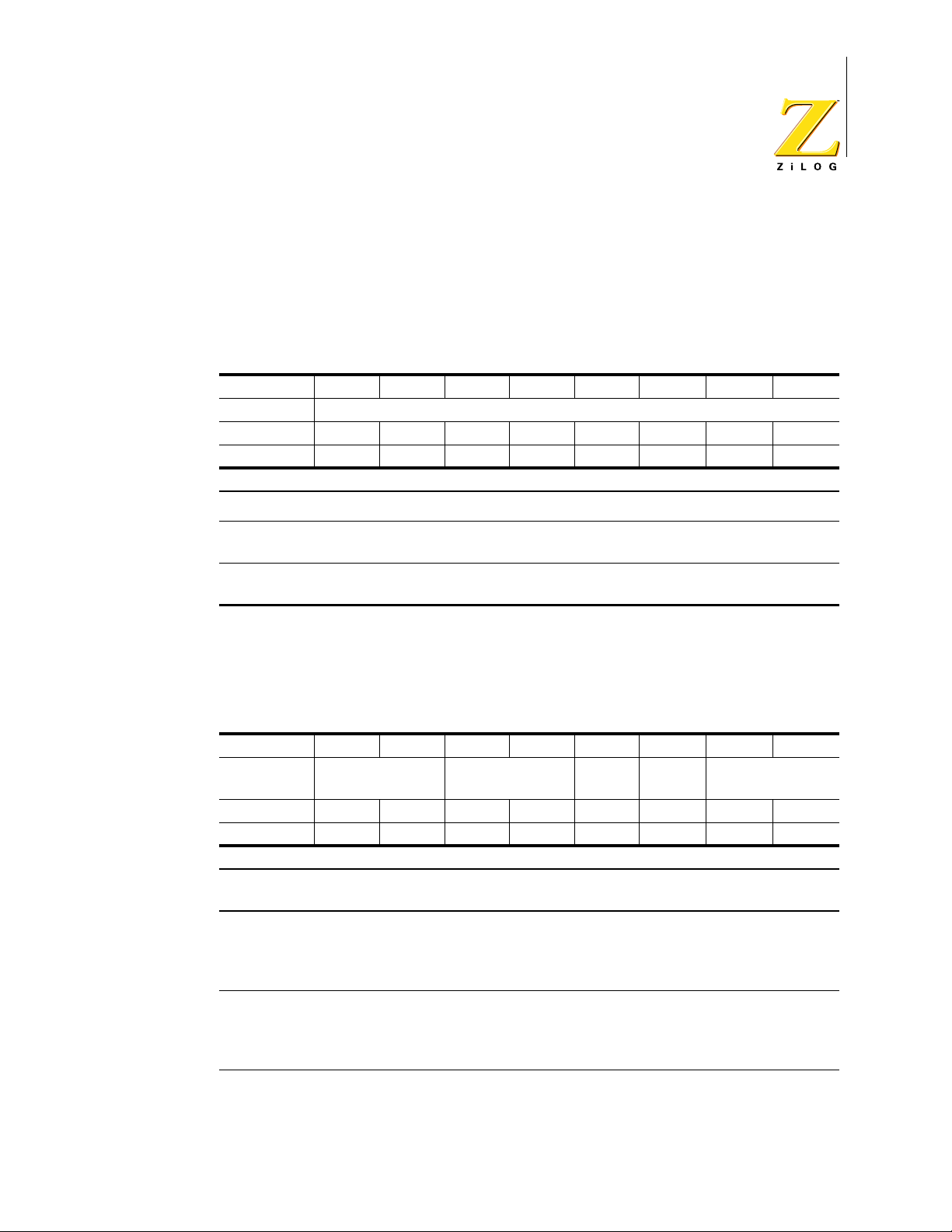
Z86D990/Z86D991 OTP and Z86L99X ROM
Low-Voltage Microcontrollers with ADC
T1 Data Register (T1)
The counter/timer register (T1) consists of an 8-bit down counter, a write-only register that holds the initial count value, and a read-only register that holds the current count value. The initial value of T1 can range from 1 to 255 (0 represents
256) (see Table 34.)
T a ble 34.T1 Register [Group/Bank F0h, Register 2 (R242)]
Bit 76543210
Bit/Field T1_Value
R/W R/W R/W R/W R/W R/W R/W R/W R/W
Reset 00000000
R = Read, W = Write, X = Indeterminate
72
Bit
Position Bit/Field R/W Value Description
76543210 T
Value R
1
W
Data
Data
Current Value
Initial Value (Range 1 to 256 Decimal)
T1 Mode Register (TMR)
Under software control, T1 counter/ timer is started and stopped using the T1
Mode Register as shown in Table 35.
T able 35.TMR Register [Group/Bank F0h, Register 1 (R241)]
Bit 76543210
T1_
Bit/Field TOUT_Mode TIN_Mode
Count
R/W R/W R/W R/W R/W R/W R/W R/W R/W
Reset 00000011
R = Read, W = Write, X = Indeterminate
Bit
Position Bit/Field R/W Value Description
76______ T
__54____ T
____3___ T
Mode R/W 11
OUT
Mode R/W 11
IN
Count R/W 1
1
10
01
00
10
01
00
0
Internal Clock OUT on P56
T
OUT on P56
1
Reserved
Not used (P56 configured as I/O)
Trigger Input (Retriggerable)
Trigger Input (Not-retriggerable)
Gate Input
External Clock Input (T
Enable T1 Count
Disable T
T1_
Load Reserved
on P52)
IN
Count
1
PS003807-1002 P R E L I M I N A R Y
Page 80

Z86D990/Z86D991 OTP and Z86L99X ROM
Low-Voltage Microcontrollers with ADC
Table 35.TMR Register [Group/Bank F0h, Register 1 (R241)] (Continued)
73
_____2__ T1 Load R/W 1
______10 Reserved R
W
0
1
X
Load T
No effect
Always reads
No effect
1
11
T1 Prescale Register (PRE1)
The T1 prescaler consists of an 8-bit regi ster and a 6-bit down-counter. The six
most significant bits (D2–D7) of PRE1 hold the prescaler’s count modulo, a value
from 1 to 64 decimal, as shown in Table 36. The prescale register also contains
control bits that specify the counting mode and clock source for T1.
Table 36.PRE1 Register [Group/Bank F0h, Register 3 (R243)]
Bit 76543210
Clock_
Bit/Field Prescaler_Modulo
R/W R/W R/W R/W R/W R/W R/W R/W R/W
Reset 00000000
R = Read, W = Write, X = Indeterminate
Bit
Position Bit/Field R/W Value Description
765432__ Prescaler Modulo R/W Data Range: 1 to 64 Decimal
_______1_ Clock Source R/W 1
0
________0 Count Mode R/W 1
0
T
Internal
1
T
External (T
1
T
Modulo-n
1
T
Single Pass
1
on P52)
IN
Source
Count_
Mode
Timer Control Registers—T8 and T16 Timers
One of the unique features of the Z86D99/Z86L99 family is a special timer architecture to automate the generation and reception of complex pulses or signals.
This timer architecture consists of one programmable 8-bit counter timer with two
capture registers and two load register s and a programmable 16- bit count er/ti mer
with one 16-bit capture register pair and one 16-bit load register pair and their
associated control regist ers. These cou nter /ti mers can wor k independe ntl y or c an
be combined together using a number of user-selectable modes governed by the
T8/T16 control registers.
PS003807-1002 P R E L I M I N A R Y
Page 81

T8/T16 Control Register A (CTR1)
Z86D990/Z86D991 OTP and Z86L99X ROM
Low-Voltage Microcontrollers with ADC
74
The T8/T16 Control Register A controls the functions in common with both the T
and T
counter/timers. The T8 and T16 counter/timers have two primary modes of
16
8
operation: Transmit Mode and Demodulation Mode. Transmit Mode is used for
generating complex waveforms. The Transmit Mode has two submodes: Normal
Mode and Ping-Pong Mode. The settings for CTR1 in Trans mit Mode are given in
Table 37.
Table 37.CTR1 Register (In Transmit Mode) (Group/Bank 0Dh, Register 1)
Bit 76543210
Initial_
P43
Bit/Field Mode
R/W R/W R/W R/W R/W R/W R/W R/W R/W
Reset 00000000
R = Read, W = Write, X = Indeterminate
Bit
Position Bit/Field R/W Value Description
7_______ Mode R/W 1
_6______ P43_Out R/W 1
__54____ T
____32__ Transmit_
______1_ Initial_T8_Out R/W 1
_______0 Initial_T16_Out R/W 1
8/T16
Submode
Out T8/T16_Logic
0
0
Logic R/W 11
10
01
00
R/W 11
10
01
00
0
0
Transmit_
Submode
Demodulation
Transmit
P43 configured as T8/T16 Output
P43 configured as I/O
NAND
NOR
OR
AND
T16_Out = 1
T16_Out = 0
Ping-Pong Mode
Normal Operation
T8_Out set to 1 initially
T8_Out set to 0 initially
T16_Out set to 1 initially
T16_Out set to 0 initially
Initial_
T8_Out
T16_
Out
PS003807-1002 P R E L I M I N A R Y
Page 82

Z86D990/Z86D991 OTP and Z86L99X ROM
Low-Voltage Microcontrollers with ADC
In Demodulation Mode, the T8 and T16 counter/timers are used to capture and
demodulate complex waveforms. The settings for CTR1 in Demodulation Mode
are given in Table 38.
Table 38.CTR1 Register (in Demodulation Mode) (Group/Bank 0Dh, Register 1)
Bit 76543210
Demod
Bit/Field Mode
R/W R/W R/W R/W R/W R/W R/W R/W R/W
Reset 00000000
R = Read, W = Write, X = Indeterminate
Bit
Position Bit/Field R/W Value Description
7_______ Mode R/W 1
_6______ Demodulator_
Input
__54____ Edge_Detect R/W 11
____32__ Glitch_Filter R/W 11
______1_ Rising_Edge R
_______0 Falling_Edge R
_Input Edge_Detect Glitch_Filter
Demodulation
R/W 1
R
W
W
R
W
W
0
0
10
01
00
10
01
00
1
0
1
0
1
0
1
0
Transmit
P20 as Demodulator Input
P51 as Demodulator Input
Reserved
Both Edges
Rising Edge
Falling Edge
16 SCLK Cycles
8 SCLK Cycles
4 SCLK Cycles
No Filter
Rising Edge Detected
No Rising Edge
Reset Flag to 0
No Effect
Falling Edge Detected
No Falling Edge
Reset Flag to 0
No Effect
Rising
Edge
Falling
Edge
75
PS003807-1002 P R E L I M I N A R Y
Page 83

Z86D990/Z86D991 OTP and Z86L99X ROM
Low-Voltage Microcontrollers with ADC
T8/T16 Control Register B (CTR3)
The T8/T16 Control Register B, known as CTR3, is a new register to the Z86D99/
Z86L99 family. This register allows the T
and T16 counters to be synchronized.
8
The settings of CTR3 are described in Table 39.
T able 39.CTR3 Register (Group/Bank 0Dh, Register 3)
Bit 76543210
T16_
Bit/Field
R/W R/W R/W R/W R/W R/W R/W R/W R/W
Reset 000XXXXX
R = Read, W = Write, X = Indeterminate
Bit
Position Bit/Field R/W Value Description
7_______ T
_6______ T
__5_____ Sync Mode R/W 1
___43210 Reserved R
Enable
16
Enable R
8
T8_
Enable
Enable R
Sync
Mode Reserved
1
R
W
W
R
W
W
W
0
1
0
1
0
1
0
0
1
X
Counter Enabled
Counter Disabled
Enable Counter
Stop Counter
Counter Enabled
Counter Disabled
Enable Counter
Stop Counter
Enable Sync Mode
Diable Sync Mode
Always reads
No Effect
11111
76
PS003807-1002 P R E L I M I N A R Y
Page 84

Z86D990/Z86D991 OTP and Z86L99X ROM
Low-Voltage Microcontrollers with ADC
T8 Control Register (CTR0)
As shown in Table 40, the T8 Control Register, known as CTR0, controls the operation of the 8-bit T
T able 40.CTR0 Register (Group/Bank 0Dh, Register 0)
Bit 76543210
T8_
Bit/Field
R/W R/W R/W R/W R/W R/W R/W R/W R/W
Reset 00000000
R = Read, W = Write, X = Indeterminate
Bit
Position Bit/Field R/W Value Description
7_______ T
_6______ Single/
__5_____ Time_Out R
___43___ T
_____2__ Capture Interrupt
______1_ Counter Interrupt
_______0 P40_Out R/W 1
Enable
Modulo-n
Mask
Mask
timer.
8
Single/
Modulo-n
Enable R
8
Time_
Out T8_Clock
R
W
W
R/W 1
R
W
W
Clock R/W 11
8
R/W 1
R/W 1
1
0
1
0
0
1
0
1
0
10
01
00
0
0
0
Capture
INT_
Mask
Counter
INT_
Mask
Counter Enabled
Counter Disabled
Enable Counter
Stop Counter
Single Pass
Modulo-n
Counter Timeout Occurred
No Counter Timeout
Reset Flag to 0
No Effect
SCLK/8
SCLK/4
SCLK/2
SCLK
Enable Data Capture Interrupt
Disable Data Capture Interrupt
Enable Time_Out Interrupt
Disable Time_Out Interrupt
P40 configured as T
Output
8
P40 configured as I/O
P40_
Out
77
PS003807-1002 P R E L I M I N A R Y
Page 85

Z86D990/Z86D991 OTP and Z86L99X ROM
Low-Voltage Microcontrollers with ADC
T8 High Capture Register (HI8)
The T8 High Capture Register, as described in Table 41, holds the captured data
from the output of the T
number of counts when the input signal is high (or
Table 41.HI8 Register (Group/Bank 0Dh, Register B)
Bit 76543210
Bit/Field T8_Capture_HI
R/W R/W R/W R/W R/W R/W R/W R/W R/W
Reset 00000000
R = Read, W = Write, X = Indeterminate
Bit
Position Bit/Field R/W Value Description
76543210 T
Capture
8
High Value
counter/timer. This register is typically used to hold the
8
1).
R
W
Data Captured Data
No Effect
78
T8 Low Capture Register (LO8)
The T8 Low Capture Register, as described in Table 42, holds the captured data
from the output of the T
number of counts when the input signal is low (or
Table 42.LO8 Register (Group/Bank 0Dh, Register A)
Bit 76543210
Bit/Field T8_Capture_LO
R/W R/W R/W R/W R/W R/W R/W R/W R/W
Reset 00000000
R = Read, W = Write, X = Indeterminate
Bit
Position Bit/Field R/W Value Description
76543210 T
Capture
8
Low Value
counter/timer. This register is typically used to hold the
8
0).
R
W
Data Captured Data
No Effect
PS003807-1002 P R E L I M I N A R Y
Page 86

Z86D990/Z86D991 OTP and Z86L99X ROM
Low-Voltage Microcontrollers with ADC
T8 High Load Register (TC8H)
The T8 High Load Register, as described in Table 43, is loaded with the counter
value necessary to keep the T8_Out signal in the high state for the required time.
T a ble 43.TC8H Register (Group/Bank 0Dh, Register 5)
Bit 76543210
Bit/Field T8_Level_HI
R/W R/W R/W R/W R/W R/W R/W R/W R/W
Reset 00000000
R = Read, W = Write, X = Indeterminate
Bit
Position Bit/Field R/W Value Description
76543210 T
Level
8
High Value
R/W Data Duration that T8_Out remains High
79
T8 Low Load Register (TC8L)
The T8 Low Load Register, as described in Table 44, is loaded with the counter
value necessary to keep the T8_Out signal in the low stat e for the required time.
Table 44.TC8L Register (Group/Bank 0Dh, Register 4)
Bit 76543210
Bit/Field T8_Level_LO
R/W R/W R/W R/W R/W R/W R/W R/W R/W
Reset 00000000
R = Read, W = Write, X = Indeterminate
Bit
Position Bit/Field R/W Value Description
76543210 T
Level
8
Low Value
R/W Data Duration that T8_Out remains Low
PS003807-1002 P R E L I M I N A R Y
Page 87

T16 Control Register (CTR2)
Z86D990/Z86D991 OTP and Z86L99X ROM
Low-Voltage Microcontrollers with ADC
80
The T16 Control Register , known as CTR2, controls the operation of the 16-b it T
16
timer (see Table 45).
T able 45.CTR2 Register (Group/Bank 0Dh, Register 2)
Bit 76543210
Single/
Bit/Field
T16_
Enable
Modulo-n
Time_
Out T16_Clock
R/W R/W R/W R/W R/W R/W R/W R/W R/W
Reset 00000000
R = Read, W = Write, X = Indeterminate
Bit
Position Bit/Field R/W Value Description
7_______ T
Enable R
16
_6______ Single/
Modulo-n
R
W
W
R/W
1
0
1
0
1
0
Counter Enabled
Counter Disabled
Enable Counter
Stop Counter
In Transmit Mode:
Single Pass
Modulo-n
In Demodulation Mode:
T
16
T
16
Counter Timeout Occurred
No Counter Timeout
Reset Flag to 0
No Effect
SCLK/8
SCLK/4
SCLK/2
SCLK
Enable Data Capture Interrupt
Disable Data Capture Interrupt
Enable Time_Out Interrupt
Disable Time_Out Interrupt
P41 configured as T
P41 configured as I/O
__5_____ Time_Out R
R
W
W
___43___ T
_____2__ Capture Interrupt
Clock R/W 11
16
R/W 1
Mask
______1_ Counter Interrupt
R/W 1
Mask
_______0 P41_Out R/W 1
1
0
1
0
1
0
10
01
00
0
0
0
Capture
INT_
Mask
Counter
INT_
Mask
Does Not Recognize Edge
Recognizes Edge
Output
16
P41_
Out
PS003807-1002 P R E L I M I N A R Y
Page 88

Z86D990/Z86D991 OTP and Z86L99X ROM
Low-Voltage Microcontrollers with ADC
T16 MS-Byte Capture Register (HI16)
The T16 MS-Byte Capture Register, as described in Table 46, holds the captured
data from the output of the T
counter/timer. This register holds the most signifi-
16
cant byte of the data.
Table 46.HI16 Register (Group/Bank 0Dh, Register 9)
Bit 76543210
Bit/Field T16_Capture_HI
R/W R/W R/W R/W R/W R/W R/W R/W R/W
Reset 00000000
R = Read, W = Write, X = Indeterminate
Bit
Position Bit/Field R/W Value Description
76543210 T
Capture HI R
16
W
Data MS-Byte of Captured Data
No Effect
81
T16 LS-Byte Capture Register (LO16)
The T16 LS-Byte Capture Register, as described in Table 47, holds the captured
data from the output of the T
counter/timer. This register holds the least signifi-
16
cant byte of the data.
T a ble 47.LO16 Register (Group/Bank 0Dh, Register 8)
Bit 76543210
Bit/Field T16_Capture_LO
R/W R/W R/W R/W R/W R/W R/W R/W R/W
Reset 00000000
R = Read, W = Write, X = Indeterminate
Bit
Position Bit/Field R/W Value Description
76543210 T
Capture LO R
16
W
Data LS-Byte of Captured Data
No Effect
PS003807-1002 P R E L I M I N A R Y
Page 89

Z86D990/Z86D991 OTP and Z86L99X ROM
Low-Voltage Microcontrollers with ADC
T16 MS-Byte Load Register (TC16H)
The T16 MS-Byte Load Register, as described in Table 48, is loaded with the most
significant byte of the T
Table 48.TC16H Register (Group/Bank 0Dh, Register 7)
Bit 76543210
Bit/Field T16_Data_HI
R/W R/W R/W R/W R/W R/W R/W R/W R/W
Reset 00000000
R = Read, W = Write, X = Indeterminate
Bit
Position Bit/Field R/W Value Description
76543210 T
Data HI R/W Data MS-Byte of the T16 Counter
16
counter value.
16
82
T16 LS-Byte Load Register (TC16L)
The T16 LS-Byte Load Register, as described in Table 49, is loaded with the least
significant byte of the T
Table 49.TC16L Register (Group/Bank 0Dh, Register 6)
Bit 76543210
Bit/Field T16_Data_LO
R/W R/W R/W R/W R/W R/W R/W R/W R/W
Reset 00000000
R = Read, W = Write, X = Indeterminate
Bit
Position Bit/Field R/W Value Description
76543210 T
Data LO R/W Data LS-Byte of the T16 Counter
16
counter value.
16
Stop-Mode Recovery Control Registers
The Z86D99/Z86L99 family of products allows 16 indivi dual I/O pins (Ports 2 and
5) to be used as a stop-mode recovery sources. The STOP mode is exited when
one of these SMR sources is toggled.
PS003807-1002 P R E L I M I N A R Y
Page 90

Z86D990/Z86D991 OTP and Z86L99X ROM
Low-Voltage Microcontrollers with ADC
Stop-Mode Recovery Register
The SMR register serves two functions. Bit D7 of the SMR register, as shown in
Table 50, is the Stop Mode Flag that is set upon entering st op mode. A 0 in this bit
indicates that the device has been reset by a POR or WDT Reset. A POR or WDT
Reset is sometimes referred to as a “cold” start. A 1 in bit D7 indicates that the
device was awakened by a SMR source. Waking a device with a SMR source is
sometimes referred to as a “warm” start.
The Stop Mode Recovery source can be selected by any combination of P2 and
P5 by P2SMR and P5SMR, respectively. If the pin is selected as the SMR source,
its logic level i s latched int o a register. A wait up signal is generated if it s logic level
changes. This applies to all selected pins for the SMR source.
The comparators of P5 cannot be used as an SMR source. The comparator is
turned off in STOP mode.
83
Table 50.SMR Register (Group/Bank 0Fh, Register B)
Bit 76543210
Stop
Bit/Field
R/W R R/W W R/W R/W R/W W W
Reset 00100000
R = Read, W = Write, X = Indeterminate
Bit
Position Bit/Field R/W Value Description
7_______ Stop Mode Flag R
_6______ Reserved R
__5_____ Stop Delay R
___432__ Reserved R
_______10 System Clock
Flag
Select
Reserved
Stop
Delay Reserved SCLK Select
R
W
W
W
W
W
R
W
W
W
W
1
0
X
1
X
1
1
0
1
X
11
11
10
01
00
Stop Recovery (warm start)
POR/WDT Reset (cold start)
No Effect
Always reads
No Effect
Always reads
Enable 5ms /Reset delay
Disable /Reset delay after SMR
Always reads
No Effect
Always reads
SCLK, TCLK = XTAL/16
SCLK, TCLK = XTAL
SCLK, TCLK = XTAL/32
SCLK, TCLK = XTAL/2
1
1
111
11
The second function of the SMR register is the selection of the external clock
divide value. The purpose of this control is to select ively reduce device power
PS003807-1002 P R E L I M I N A R Y
Page 91
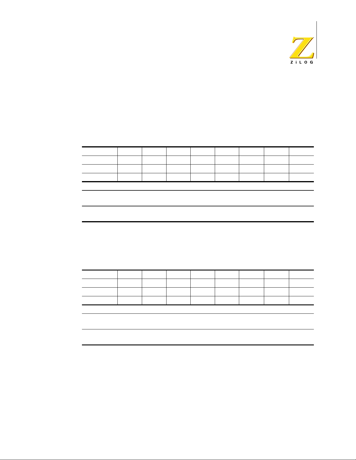
Z86D990/Z86D991 OTP and Z86L99X ROM
Low-Voltage Microcontrollers with ADC
consumption during normal processor execution (SCLK control) and/or HALT
mode (where TCLK sources counter/timers and interrupt logic).
Port 2 Stop Mode Recovery (P2SMR)
The P2SMR register, as described in Table 51, defines which I/O lines in Port 2
are to be used as stop mode recovery sources.
Table 51.P2SMR Register (Group/Bank 0Fh, Register 1)
Bit 76543210
Bit/Field P27RS P26RS P25RS P24RS P23RS P22RS P21RS P20RS
R/W R/W R/W R/W R/W R/W R/W R/W R/W
Reset 00000000
R = Read, W = Write, X = Indeterminate
Bit
Position Bit/Field R/W Value Description
76543210
(by bit)
Port 2 Stop Mode
Recovery
R/W 1
Recovery Source
0
Not
84
Port 5 Stop-Mode Recovery (P5SMR)
The P5SMR register, as described in Table 52, defines which I/O lines in Port 5
are to be used as stop-mode recovery sources.
Table 52.P5SMR Register (Group/Bank 0Fh, Register 5)
Bit 76543210
Bit/Field P57RS P56RS P55RS P54RS P53RS P52RS P51RS P50RS
R/W R/W R/W R/W R/W R/W R/W R/W R/W
Reset 00000000
R = Read, W = Write, X = Indeterminate
Bit
Position Bit/Field R/W Value Description
76543210
(by bit)
Port 5 Stop Mode
Recovery
R/W 1
Recovery Source
0
Not
PS003807-1002 P R E L I M I N A R Y
Page 92

Electrical Char ac te ris t ic s
This section covers the absolute maximum rati ngs, standard test conditions, DC
characteristics, and AC characteristics.
Absolute Maximum Ratings
Table 53 lists the absolute maximum ratings.
Table 53.Absolute Maximum Ratings
Symbol Description Min Max Units
V
MAX
T
STG
T
A
V
RAM
Note:
*Voltage on all pins with respect to GND.
†See “Ordering Information” on page 95.
** Estimated value, not tested.
Supply Voltage (*) –0.3 +7.0 V
Storage Temp. –65° +150° C
Oper. Ambient Temp. † C
Minimum RAM Voltage 1.0 V**
Z86D990/Z86D991 OTP and Z86L99X ROM
Low-Voltage Microcontrollers with ADC
85
Str esses greater than those listed in the preceding table can cause permanent
damage to the device. This rating is a stress rating only. Functional operation of
the device at any condition above those indicated in the operational sections of
these specifications is not implied. Exposure to absolute maximum rating conditions for an extended period can affect device reliability.
Standard Test Conditions
The characteristics listed below apply for standard test conditions as noted. All
voltages are referenced to GND. Positive current flows into the referenced pin
(see Figure 36).
PS003807-1002 P R E L I M I N A R Y
Page 93

From Output
Under Test
Z86D990/Z86D991 OTP and Z86L99X ROM
Low-Voltage Microcontrollers with ADC
86
Figure 36. Test Load Diagram
DC Characteristics
Table 54 lists the DC characteristics for the Z86D99X (OTP only). Table 55 lists
the DC characteristics for the Z86L99X (mask only).
I
150pF
PS003807-1002 P R E L I M I N A R Y
Page 94

Z86D990/Z86D991 OTP and Z86L99X ROM
Low-Voltage Microcontrollers with ADC
Ta ble 54.DC Characteristics for the Z86D99X (OTP Only)
87
Symbol Parameter V
V
V
V
V
V
V
DD
CH
CL
IH
IL
OH1
Power Supply Voltage 3 5.5
Clock Input High Voltage 3.0 V
Clock Input Low Voltage 3.0 V
Input High Voltage 3.0 V
Input Low Voltage 3.0 V
Output High Voltage
Regular I/O
V
OH2
High Drive Pins (P54, P55, P56,
P57)
V
OL1
Regular I/O
Output low voltage
V
OL2
High Drive Pins (P54, P55, P56,
P57)
I
CCO
I
IL
I
CC
I
CC1
I
CC2
I
ADC
V
V
LV
LB
Controlled Current Output (P43) 3.0 V
Input Leakage 3.0 V
Supply Current 3.0 V
Standby Current (Halt Mode) 3.0 V
Standb y Cu rren t (ST OP Mo de) 3.0 V
Current with A/D Running 3.0 V
Vdd Low-Voltage Protection 2.90 V Low voltage protection
Low-Battery Detection VLV+
DD
Min Max Units Comments
0.8Vdd
5.5 V
0.8Vdd
Vss–0.3
5.5 V
Vss–0.3
0.7Vdd
5.5 V
0.7Vdd
Vss–0.3
5.5 V
3.0 V
5.5 V
3.0 V
5.5 V
Vss–0.3
VDD–0.8
V
VDD–0.8
V
3.0 V
5.5 V
3.0 V
5.5 V
5.5 V7070
5.5 V–1–1
5.5 V
3.0 V
5.5 V
5.5 V
3.0 V
5.5 V
5.5 V
5.5 V
DD
DD
–0.8
–0.8
Vdd+0.3
Vdd+0.3VV
0.2Vdd
0.2Vdd
Vdd+0.3
Vdd+0.3VV
0.2Vdd
0.2Vdd
0.4
0.8
0.4
0.8
120
120
1 µA
1 µA
10
15
250
850
3
5
2
4
20
30
500
900
0.5
V
V
V
V
V
V
V
V
V
V
mA
mA
µA
µA
mA
mA
µA
µA
mA
mA
mA
mA
µA
µA
µA
µA
V
V
Driven by Ext. clock
generator
Driven by Ext. clock
generator
–1.2 mA
–5.0 mA
2 mA
4.0 mA
4 mA
7.0 mA
Vout = 1.2 V to VDD
(see Figure 17)
Vin=0 V, Vdd
Vin=0 V, Vdd
at 8 MHz
at 8 MHz
at 32 KHz
at 32 KHz
ADC is off.
Vin=0 V, Vdd
at 8 MHz
Clock divided by 16
XTAL running
ADC is off.
Vin=0 V, Vdd; ADC is off.
P43=1 or high impedance
WDT, Comparators, Low
Voltage Detection, and ADC (if
applicable) are disabled. The
IC might draw more current if
any of the above peripherals is
enabled.
is also known as
brownout.
Typical is 2.6 V.
PS003807-1002 P R E L I M I N A R Y
Page 95

T a ble 55.DC Characteristics for the Z86L99X (Mask Only)
Symbol Parameter V
V
V
V
V
V
V
V
V
V
I
CCO
I
IL
I
CC
I
CC1
I
CC2
I
CC2
I
LV
I
ADC
V
V
DD
CH
CL
IH
IL
OH1
OH2
OL1
OL2
LV
LB
Power Supply Voltage 2.3 5.5
Clock Input High Voltage 2.3 V
Clock Input Low Voltage 2.3 V
Input High Voltage 2.3 V
Input Low Voltage 2.3 V
Output High Voltage
Regular I/O
High Drive Pins (P54, P55, P56, P57) 2.3 V
Regular I/O
Output low voltage
High Drive Pins (P54, P55, P56, P57) 2.3 V
Controlled Current Output (P43) 2.3 V
Input Leakage 2.3 V
Supply Current 2.3 V
Standby Current (Halt Mode) 2.3 V
Standby Current (STOP Mode) 2.3 V
Standby Current (STOP Mode) 5.5 V 15 µA
Standby Current (Low Voltage) 20 µA Measured at VDD=VLV–0.2 V.
Current with A/D Running 2.3 V
Vdd Low-Voltage Protection 2.2 V
Low-Battery Detection 3.0 V Typical is around 2.4 V at room temperature.
Z86D990/Z86D991 OTP and Z86L99X ROM
Low-Voltage Microcontrollers with ADC
Min Max Units Comments
DD
0.8Vdd
5.5 V
0.8Vdd
Vss–0.3
5.5 V
Vss–0.3
0.7Vdd
5.5 V
0.7Vdd
Vss–0.3
5.5 V
Vss–0.3
2.3 V
2.0
5.5 V
5.0
2.3 V
1.9
5.5 V
5.0
1.9
5.5 V
5.1
2.3 V
1.7
5.5 V
4.7
2.3 V
5.5 V
2.3 V
5.5 V
5.5 V
2.3 V
5.5 V
5.5 V7070
5.5 V–1–1
5.5 V
2.3 V
5.5 V
5.5 V
5.5 V
5.5 V
Vdd+0.3
Vdd+0.3VV
0.2Vdd
0.2Vdd
Vdd+0.3
Vdd+0.3VV
0.2Vdd
0.2VddVV
V
V
V
V
V
V
V
V
0.4 V
0.4 VVV
0.8 V
0.8 VVV
0.4 V
0.4 VVV
0.8 V
0.8 VVV
120
mAmAVout = 1.2 V to VDD at room
120
1 µA
1 µAµAµA
3
8
250
850
2
mA
mA
µA
µA
mAmAVin=0 V, Vdd
5
8
25.0
500
900
µA
µA
µA
µA
Driven by Ext. clock generator
Driven by Ext. clock generator
–0.5 mA
–1.2 mA
–3 mA
–5 mA
2 mA
4 mA
4 mA
7 mA
temperature (see Figure 17)
Vin=0 V, Vdd
Vin=0 V, Vdd
at 8 MHz
at 8 MHz
at 32 KHz
at 32 KHz
ADC is off.
at 8 MHz
Vin=0 V, Vdd;ADC is off.
WDT, Comparators, Low Voltage Detection,
and ADC (if applicable) are disabled. The IC
might draw more current if any of the above
peripherals is enabled.
at 30 °C
Low voltage protection is also known as
brownout.
Typical is around 1.7 V at room temperature.
88
PS003807-1002 P R E L I M I N A R Y
Page 96

Z86D990/Z86D991 OTP and Z86L99X ROM
Low-Voltage Microcontrollers with ADC
Analog-to-Digital Converter Characteristics
Table 56 lists the analog-to-digital converter characteristics.
T a ble 56.Analog-to-Digital Converter Characteristics
Parameter Minimum Typical Maximum Units
Resolution 8bits
Integral Nonlinearity 0.5 1 LSB
Differential Nonlinearity 0.5 1 LSB
Zero Error at 25 °C7.8mV
Supply Voltage Range (OTP) 3.0 5.5 V
Supply Voltage Range (ROM) 2.3 5.5 V
89
Power Dissipation (No Load) 1.2 mW
Clock Frequency (f ADC) 4 MHz
Input Voltage Range V
Ref–
V
V
Ref+
Ste p Resp onse 2/(0.0021 X f ADC ) s
ADC Input Capacitance 25 40 pF
Vref Input Capacitance 25 40 pF
V
Range V
Ref+
V
Range AGND V
Ref–
(V
Ref+
)–(V
)2.0 AVDDV
Ref–
+2.0 AV
Ref–
DD
–2.0 V
Ref+
V
Temperature Range 0 70 °C
3-db Frequency (0.0021 X f ADC) Hz
Signal to Noise 47 db
ADC Output Code Dout
Vref Input Source Impedance 1.0 kOhms
ADC Input Source Impedance 1.0 kOhms
Notes: Dout= [(Vin–V
f ADC = set in ADCCTRL configuration register
Step Response is the time to track the input if a step from V
Ref–
)/(V
Ref+–VRef–
)] X 256
Ref–
to V
is applied.
Ref+
The ADC input is a switching capacitor that charges up to the applied input voltage whenever it is configured as an ADC input. If you swi tch it from digital mode t o
PS003807-1002 P R E L I M I N A R Y
Page 97

the ADC input mode, the switching capacitor starts to charge up from 0 V. For the
maximum swing (Dout = 0 to FF), it takes 2/(0.0021x f ADC). For an 8-MHz MCU
crystal (with clock divide-by-two mode), the internal system clock is 4 MHz. In
ADCCTRL, if you select the ADC frequency = system clock divided by 1 option,
f ADC = 4 MHz. The step response = 238 uS.
AC Characteristics
Table 57 lists the AC characteristics.
Table 57.AC Characteristics
No. Symbol Parameter VDD Min Max Units
1 TpC Input Clock Period 2.3 V
2 TrC, TfC Clock Input Rise and Fall Times 2.3 V
3 TwC Input Clock Width 2.3 V
4 TwTinL Timer Input Low Width 2.3 V
5 TwTinH Timer Input High Width 2.3 V
6 TpT1in Timer 1 Input Period 2.3 V
7 TrTin, TfTin Timer Input Rise and Fall Time 2.3 V
8 TwIL Interrupt Request Low Time 2.3 V
9 TwIH Interrupt Request Input High Time 2.3 V
10 Twsm Stop-Mode Recovery Width Spec 2.3 V
12 Twdt Watch-Dog Timer Time Out 2.3 V
Z86D990/Z86D991 OTP and Z86L99X ROM
Low-Voltage Microcontrollers with ADC
120
5.5 V
5.5 V
5.5 V
5.5 V
5.5 V22
5.5 V88
5.5 V
5.5 V
5.5 V55
5.5 V1212
5.5 V2510
120
5.0
5.0
2TPC
2TPC ns
100
70
DC
DC
25 ns
25 ns
100
100
ns
ns
ns
TpC
TpC
TpC
TpC
ns
ns
ns
ns
TpC
TpC
ns
ns
ms
ms
90
PS003807-1002 P R E L I M I N A R Y
Page 98

Packaging
Z86D990/Z86D991 OTP and Z86L99X ROM
Low-Voltage Microcontrollers with ADC
91
Figure 37 through Figure 40 show the available packages.
D
48 25
E H
1 24
A1
e
b
Detail A
A2
SEATING PLANE
L
0-8˚
c
Detail A
A
CONTROLLING DIMENSIONS : MM
LEADS ARE COPLANAR WITHIN .004 INCH
Figure 37. 48-Pin SSOP
PS003807-1002 P R E L I M I N A R Y
Page 99

Z86D990/Z86D991 OTP and Z86L99X ROM
Low-Voltage Microcontrollers with ADC
92
Figure 38. 40-Pin PDIP
Figure 39. 28-Pin PDIP
PS003807-1002 P R E L I M I N A R Y
Page 100

Z86D990/Z86D991 OTP and Z86L99X ROM
Low-Voltage Microcontrollers with ADC
93
Figure 40. 28-Pin SOIC
PS003807-1002 P R E L I M I N A R Y
 Loading...