

Page 1

Z16FMC™ Series Motor Control
Development Kit
Quick Start Guide
QS007901-1110
Introduction
This quick start guide describes how to set up Zilog’s ZNEO™ Z16FMC Series Motor
Control Development Kit and use it to evaluate your motor control designs and applications.
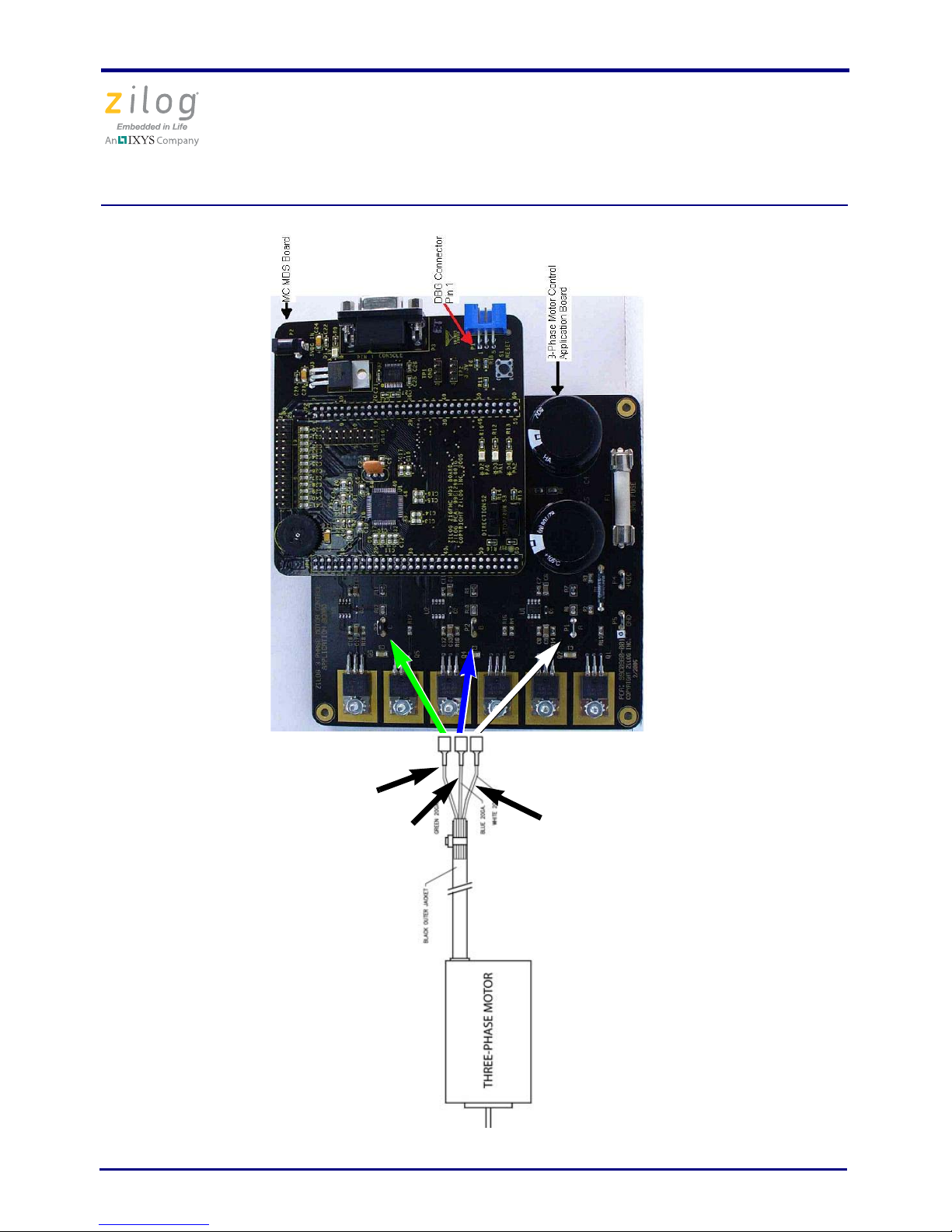
The Z16FMC Series Motor Control Development Kit features a Motor Control Modular
Development System (MC MDS) daughter board mounted on a 3-Phase Motor Control
Application Board (see Figure 1). The MC MDS board consists of a 64LQFP Z16FMC
chip and a DBG connector to connect the kit to a host development PC via the USB Smart
Cable. The 3-Phase Motor Control Application Board provides spade lug connectors for
the 3-phase motor and fused spade lug connectors for an adjustable 24 V DC, 3 A workbench power source.
This document guides you through the following elements:
• Power supply requirements to power the 3-phase motor supplied with the kit
• How to run the kit’s preloaded sample code in standalone mode
• How to connect the kit to your development PC
• Running the sample code in Zilog Developer System II (ZDS II) Debug mode
Kit Contents
All hardware (except an external adjustable power supply) and software/documentation
required to evaluate the Zilog
Series Motor Control Development Kit. For details on kit contents, refer to the Z16FMC
Series Motor Control Development Kit Packing List (PAK0025). The sample code used in
this development kit is based on the Zilog Application Note titled Sensorless BLDC Motor
Control Using the ZNEO Z16FMC MCU (AN0311). The latest sample code for this docu-
ment, AN0311-SC01, can be downloaded at www.zilog.com
®
motor control solution is included within the Z16FMC
.
System Requirements
Table 1 lists the system requirements for running ZDS II.
Copyright ©2010 Zilog®, Inc. All rights reserved.
www.zilog.com
Page 2

Z16FMC Series Motor Control Development Kit
Caution:
Table 1. ZDS II System Requirements
Recommended Configuration Minimum Configuration
Quick Start Guide
• Windows XP Professional SP3 or later
• Pentium IV 2.2GHz processor or higher
• 1024MB RAM or higher
• 135 MB hard disk space
• Super VGA Video Adapter
• CD-ROM for installation
• RS232 communication port with
hardware flow control
• USB High-Speed port (when using USB
Smart Cable)
• Ethernet port (when using Ethernet
Smart Cable)
• Internet browser (Internet Explorer or
Netscape)
• Windows XP Professional SP3
• Pentium IV 1.2GHz processor
• 512 MB RAM
• 25 MB hard disk space (Application only)
• Super VGA Video Adapter
• CD-ROM for installation
• RS232 communication port with
hardware flow control
• USB High-Speed port (when using USB
Smart Cable)
• Ethernet port (when using Ethernet
Smart Cable)
• Internet browser (Internet Explorer or
Netscape)
Always use a grounding strap to prevent damage resulting from electrostatic discharge (ESD).
External Power Supply Requirements
The 3-phase motor shipped with your development kit requires power from an adjustable
external power source. The external power source must provide 0 V DC to 24 V DC power
at 3 A. The adjustable power supply leads must be fitted with spade lugs that connects to
spade lugs (P4 and P5) on the 3-Phase Motor Control Application Board (see Figure 1).
Running in Standalone Mode
The Z16FMC Series Motor Control Development Kit is shipped with the sample code from
the Application Note titled
MCU (AN0311)
Observe the steps in this section to set up the kit and run the sample code in standalone mode.
Step 1. Connect the 3-Phase Motor to the Board
The 24 V DC 3-phase motor included with the kit features three spade connectors that plug
into spade lugs P1, P2, and P3 on the 3-Phase Motor Control Application Board. Connect
QS007901-1110 Page 2 of 15
preloaded into the Z16FMC chip’s internal Flash memory.
Sensorless Brushless DC Motor Control with the Z16FMC
Page 3

Z16FMC Series Motor Control Development Kit
Quick Start Guide
the motor leads to the spade lugs on the 3-Phase Motor Control Application Board as
shown in Figure 2.
Figure 1. MC MDS Board Mounted on 3-Phase Motor Control Application Board
Step 2. Set Switches
For your initial setup, set the switches on the board as detailed below.
• Set Direction Switch S2 to the far right position
• Set Switch S3 to the far right/RUN position
• Set Speed Potentiometer R7 to its midpoint
Refer to the Z16FMC Motor Control Development Kit User Manual (UM0234) for
detailed jumper descriptions.
QS007901-1110 Page 3 of 15
Page 4
Z16FMC Series Motor Control Development Kit
White wire
Green wire
Blue wire
Quick Start Guide
Figure 2. Z16FMC Series Development Kit Motor and DBG Connections
QS007901-1110 Page 4 of 15
Page 5

Z16FMC Series Motor Control Development Kit
Caution:
Quick Start Guide
Step 3. Configure the 5 V DC Universal Power Supply
The universal power supply kit features different plug adapters in one box and the power
supply in another. The power supply ships with a slide-out plate that must be removed to
insert the location-specific plug adapter.
Observe the following steps to configure the 5 V DC universal power supply:
1. Remove the slide-out plate.
2. Select the AC plug adapter appropriate for your locale and insert it into the slot that remains after removing the slide-out plate.
3. Slide the new plug adapter into the slot until it snaps into place.
For convenience, you can leave the adapter slot cover in place and plug in a standard computer equipment AC power cord (purchased separately) between the AC cord receptacle
on the end of the power supply and an electrical outlet.
Step 4. Connect the 5 V DC Universal Power Supply
Connect the 5 V DC power supply to the MC MDS board at connector P2, then plug the
supply into an electrical outlet. The green 3.3 V DC LED D1 illuminates when power is
applied.
Step 5. Connect the Adjustable Power Supply
To avoid damage to the development kit, check the power supply connection polarities as you follow the instructions below.
1. Set your adjustable power supply to 0 V DC.
2. Connect the negative (
P5 on the 3-Phase Motor Control Application Board.
3. Connect the positive (+) lead of your adjustable power supply to spade lug connector
P4 on the 3-Phase Motor Control Application Board.
–) lead of your adjustable power supply to spade lug connector
Step 6. Apply Power to the Motor
1. Slowly increase the adjustable power supply to 24 V DC. The 3-phase motor begins to
spin.
QS007901-1110 Page 5 of 15
Page 6

Z16FMC Series Motor Control Development Kit
Quick Start Guide
The sample code has preprogrammed Direction SWITCH S2 to change the direction
of motor spin. Run/Stop SWITCH S3 is set to turn the motor ON and OFF. Speed
potentiometer R7 allows you to change the direction of motor spin and motor speed.
2. Experiment with the switches to see how simple it is to control the motor using the
Z16FMC MCU installed on the kit’s MC MDS board.
Step 7. Power Down the Motor
After seeing how the sample code operates, turn the adjustable power supply to 0 V DC
and unplug the 5 V DC universal power supply from the MC MDS board.
Executing the Sample Code
The steps below outline the basic script for executing the sample code in debug mode
using ZDS II. Each of these steps is further described in this section.
1. Stop the preloaded sample code and turn power to the 3-phase motor and MC MDS
board off.
2. Install the ZDS II–ZNEO Series Software.
3. Install the USB Smart Cable driver software and USB Smart Cable.
4. Connect the USB Smart Cable to the MC MDS board.
5. Download and run the sample code in Debug mode using ZDS II.
Step 1. Stop the Preloaded Sample Code
If you have not already done so, apply the adjustable power supply to 0 V DC and unplug
the 5 V DC universal power supply from the MC MDS board.
Step 2. Install the ZDS II–ZNEO Series Software
Observe the following steps to install the ZDS II software tool.
1. Insert the ZDS II CD into your computer’s CD-ROM drive. DemoShield launches automatically. If it does not automatically launch, go to the root of the CD-ROM and double-click the
2. DemoShield provides several installation choices. To install ZDS II right away, select
Install Zilog Developer Studio. You can install other software and accompanying
documentation later.
QS007901-1110 Page 6 of 15
launch.exe file.
Page 7

Z16FMC Series Motor Control Development Kit
Quick Start Guide
3. Follow the instructions on the screen to complete the installation.
Step 3. Install the Opto-Isolated USB Smart Cable
The opto-isolated USB Smart Cable connects the development kit to a high-speed or fullspeed USB port on your ZDS II host system. Its internal optoisolator electrically isolates
the development kit circuitry from the USB Smart Cable.
The opto-isolated USB Smart Cable is enclosed in a black box that connects to the host PC
via a USB cable (included in kit). The USB Smart Cable housing is connected to the
development kit via a six-circuit ribbon cable.
Install the opto-isolated USB Smart Cable as described below for the appropriate operating system. Do not connect power to either the MC MDS board or application board
before connecting a USB Smart Cable to the host PC and development board.
Windows Vista
Observe the following steps to install the opto-isolated USB Smart Cable for 32-bit Windows Vista systems.
1. Connect the opto-isolated USB Smart Cable to the host PC. The Found New Hard-
ware dialog box is displayed.
2. Select Locate and install driver software (recommended). The User Account Con-
trol window is displayed; click Continue. The Driver Software Installation window
is displayed, followed by the Found New Hardware-USB Smart Cable dialog box.
3. Select I don't have the disc. Show me other options.
4. Select Browse my computer for driver software (advanced).
5. Browse to one of the following driver directories:
<ZDS II Installation Directory>\device drivers\USB\x32
<ZDS II Installation CD>\device drivers\USB\x32
6. Click Next.The Windows Security dialog box is displayed.
7. Select Install this driver software anyway.
8. When the software has been installed successfully, click Close.
QS007901-1110 Page 7 of 15
Page 8

Z16FMC Series Motor Control Development Kit
Note:
Quick Start Guide
Windows XP
Observe the following steps to install the USB Smart Cable for Windows XP systems.
1. Connect the Zilog USB device to the Host PC. The Found New Hardware Wizard
should activate automatically after connecting the Zilog USB device for the first time;
Select No, not at this time if asked to connect to Windows
2. Select Install from a list or specific location (Advanced) and click Next.
If the Windows Logo testing dialog appears, select Continue Anyway.
3. Select Search for the best driver in these locations and Include this location in
search:.
®
Update.
4. Browse to the following directory and click Next:
<ZDS installation>\device drivers\USB\X32
5. Click Next after the appropriate driver information is found.
6. Click Finish to complete the installation.
Step 4. Connect the Opto-Isolated USB Smart Cable to the
MC MDS Board
Attach one end of the six-conductor ribbon cable (included) to the opto-isolated USB
Smart Cable’s six-pin DBG connector. Pin 1 of the ribbon cable is indicated by a dark
stripe (see Figure 3).
Attach the free end of the ribbon cable to the DBG connector on the MC MDS board.
QS007901-1110 Page 8 of 15
Page 9

Z16FMC Series Motor Control Development Kit
Note:
Caution:
Quick Start Guide
Figure 3. Connecting the Six-Conductor Ribbon Cable
to the Opto-Isolated USB Smart Cable
Step 5. Download and Run the Sample Code
Observe the following steps to open the Z16FMC_motordemo.zdsproj sample project
and run the sample code in Debug mode.
Ensure that the console port (P3) is connected on the serial port of your host
PC. Set the terminal to 57600, 8-N-1.
1. Ensure that the switches and jumpers on the MC MDS board are set as described in Step
2. Set Switches on page 3.
2. Connect and apply power to the development kit as described in Running in Standalone
Mode on page 2 through 6.
Do not apply power to the MC MDS board or application board unless
the USB Smart Cable is connected both to the host PC and to the development board’s DBG port.
3. Run the ZDS II software. By default, the Zilog Developer Studio II program is located
in the Start menu under:
Programs ® ZiLOG ZDS II_ZNEO_<version_number>
ZDS II_ZNEO_<version_number>
QS007901-1110 Page 9 of 15
Page 10

Z16FMC Series Motor Control Development Kit
Note:
Quick Start Guide
4. Select Open Project from the File menu. The Open Project dialog box appears.
5. Browse to the
Samples folder for the Z16FMC_motordemo.zdsproj file, located by
default in the following filepath:
c:\Program Files\ZiLOG\ZDSII_
samples
\Z16FMC\Z16FMC_Series
ZNEO_<version_number>\
6. Select the Z16FMC_motordemo.zdsproj file and click Open. The initial ZDS II pro-
gram screen opens (see Figure 4). To view the project source files, double-click the
Project Files folder on left side of the IDE interface. Double-click an individual file to
open the file in the ZDS II file editor.
The following figure is offered for reference only; it is possible that you have
a newer version of the software.
QS007901-1110 Page 10 of 15
Page 11

Z16FMC Series Motor Control Development Kit
Reset
Icon
Rebuild
All Icon
Quick Start Guide
Figure 4. Zilog Developer Studio II Opening Screen
7. Select the correct debug tool using Project Settings Debugger Debug Tool.
For example, Select USBSmartCable when using the USB Smart Cable.
8. Click F1 for additional info on how to setup the debugger.
9. Click OK.
10. Click the Rebuild All icon to build the project. Wait for the build
to complete as indicated by the Build Complete confirmation in
the Status window at the bottom of the screen.
11. Click the Reset icon to connect and download the code to the de-
velopment board.
When the Option Bits Warning dialog box shown in Figure 5
appears, click Yes to continue.
QS007901-1110 Page 11 of 15
Page 12

Z16FMC Series Motor Control Development Kit
Go
Icon
Figure 5. Option Bits Warning Dialog Box
12. Click Go to start the program.
The screen changes as illustrated in Figure 6 on page 12.
Quick Start Guide
Figure 6. Zilog Developer Studio II Active Screen
QS007901-1110 Page 12 of 15
Page 13

Z16FMC Series Motor Control Development Kit
Quick Start Guide
13. Slowly increase the adjustable 24 V DC power source from 0 V DC to 24 V DC. The 3phase motor should start running. If the motor does not run, start over from Step 3
on
page 9.
14. Use the Direction switch S2 to change the direction in which the motor spins. Use
SPEED potentiometer R7 to adjust the motor RPM.
For more information about this demonstration software, refer to the Zilog Application
Note titled Sensorless BLDC Motor Control Using the ZNEO Z16FMC MCU (AN0311).
For more information about using Zilog Developer Studio II and building projects with
your Z16FMC
Series Motor Control D
evelopment Kit, refer to the Zilog Developer Studio
II–ZNEO User Manual (UM0171).
Troubleshooting Tips
If you experience trouble running the sample code with the Z16FMC Series Motor Control
Development Kit, check the following before contacting Zilog Technical Support for
assistance:
• Verify that you are using ZDS II version 4.12.0 or later.
• Ensure that you are using the unmodified sample project code as described in Execut-
ing the Sample Code on page 6.
• Verify that you have properly connected the opto-isolated USB Smart Cable to the
host PC and the MC MDS board as described in Step 3. Install the Opto-Isolated USB
Smart Cable on page 7. Ensure that pin 1 of the cable is properly aligned with DBG
connector pin 1 of the MC MDS board.
• After you have connected the 5 V DC power supply to the MC MDS board, green
3.3 V DC LED D1 must be on. If it is not illuminated, verify that power is properly
connected to the board as described in Step 4. Connect the 5 V DC Universal Power
Supply on page 5.
• In ZDS II, navigate to Project
serial number for the USB Optoisolator Smart Cable interface is present and selected.
If the serial number is missing, reinstall the opto-isolated USB Smart Cable driver
software.
→ Settings → Debugger → Setup and verify that the
• In ZDS II, verify that Z16FMC28200KITG is selected as the target.
• In ZDS II, navigate to Project
Tool selection is USB Smart Cable.
QS007901-1110 Page 13 of 15
→ Settings → Debugger and verify that your Debug
Page 14

Z16FMC Series Motor Control Development Kit
Quick Start Guide
• In ZDS II, click the Rebuild All button. Verify that the project rebuilds with no
errors.
• Verify that the development board is not currently running any code – the motor
should not be spinning.
• Try reloading the sample project as described in Executing the Sample Code
on page
6.
If you perform these steps and cannot get the sample code to run, contact Zilog Technical
Support at support.zilog.com
.
QS007901-1110 Page 14 of 15
Page 15

Z16FMC Series Motor Control Development Kit
Warning:
Quick Start Guide
DO NOT USE IN LIFE SUPPORT
LIFE SUPPORT POLICY
ZILOG'S PRODUCTS ARE NOT AUTHORIZED FOR USE AS CRITICAL COMPONENTS IN LIFE SUPPORT DEVICES OR SYSTEMS WITHOUT THE EXPRESS
PRIOR WRITTEN APPROVAL OF THE PRESIDENT AND GENERAL COUNSEL OF
ZILOG CORPORATION.
As used herein
Life support devices or systems are devices which (a) are intended for surgical implant
into the body, or (b) support or sustain life and whose failure to perform when properly
used in accordance with instructions for use provided in the labeling can be reasonably
expected to result in a significant injury to the user. A critical component is any component in a life support device or system whose failure to perform can be reasonably
expected to cause the failure of the life support device or system or to affect its safety or
effectiveness.
Document Disclaimer
©2010 Zilog, Inc. All rights reserved. Information in this publication concerning the
devices, applications, or technology described is intended to suggest possible uses and
may be superseded. ZILOG, INC. DOES NOT ASSUME LIABILITY FOR OR PROVIDE A REPRESENTATION OF ACCURACY OF THE INFORMATION, DEVICES,
OR TECHNOLOGY DESCRIBED IN THIS DOCUMENT. ZILOG ALSO DOES NOT
ASSUME LIABILITY FOR INTELLECTUAL PROPERTY INFRINGEMENT
RELATED IN ANY MANNER TO USE OF INFORMATION, DEVICES, OR TECHNOLOGY DESCRIBED HEREIN OR OTHERWISE. The information contained within
this document has been verified according to the general principles of electrical and
mechanical engineering.
Z8, ZNEO and Z16FMC are trademarks or registered trademarks of Zilog, Inc. All other
product or service names are the property of their respective owners.
QS007901-1110 Page 15 of 15
 Loading...