

Page 1

S95 - S125 - S185 - S245
4
>
1
:
TR
OPERATING MANUAL
ISTRUZIONI D’USO
GEBRUIKSAANWIJZING
INSTRUKCJA OBS
KULLANIM KILAVUZU
ŁUGI
2
22
42
62
82
Page 2

Dear Sir, Madam,
Congratulations on the purchase of your airconditioner. You have acquired a high quality
product that, if used responsibly, will give you many years of pleasure. Please read these
instructions for use first in order to ensure the maximum life span of your airconditioner.
On behalf of the manufacturer, we provide a 24-month guarantee on all material and
production defects. Please enjoy your airconditioner.
Yours sincerely,
PVG International b.v.
Customer service department
1. READ THE DIRECTIONS FOR USE FIRST
2. IN CASE OF ANY DOUBT, CONTACT YOUR DEALER.
.
4
2
Page 3

CONTENTS
A Specifications page 4
B Parts page 4
C Before use page 6
D Installation instructions page 7
E Instructions for use page 14
F Maintenance page 18
G Protection page 18
H Problem solving page 20
I Guarantee conditions page 21
4
3
Page 4
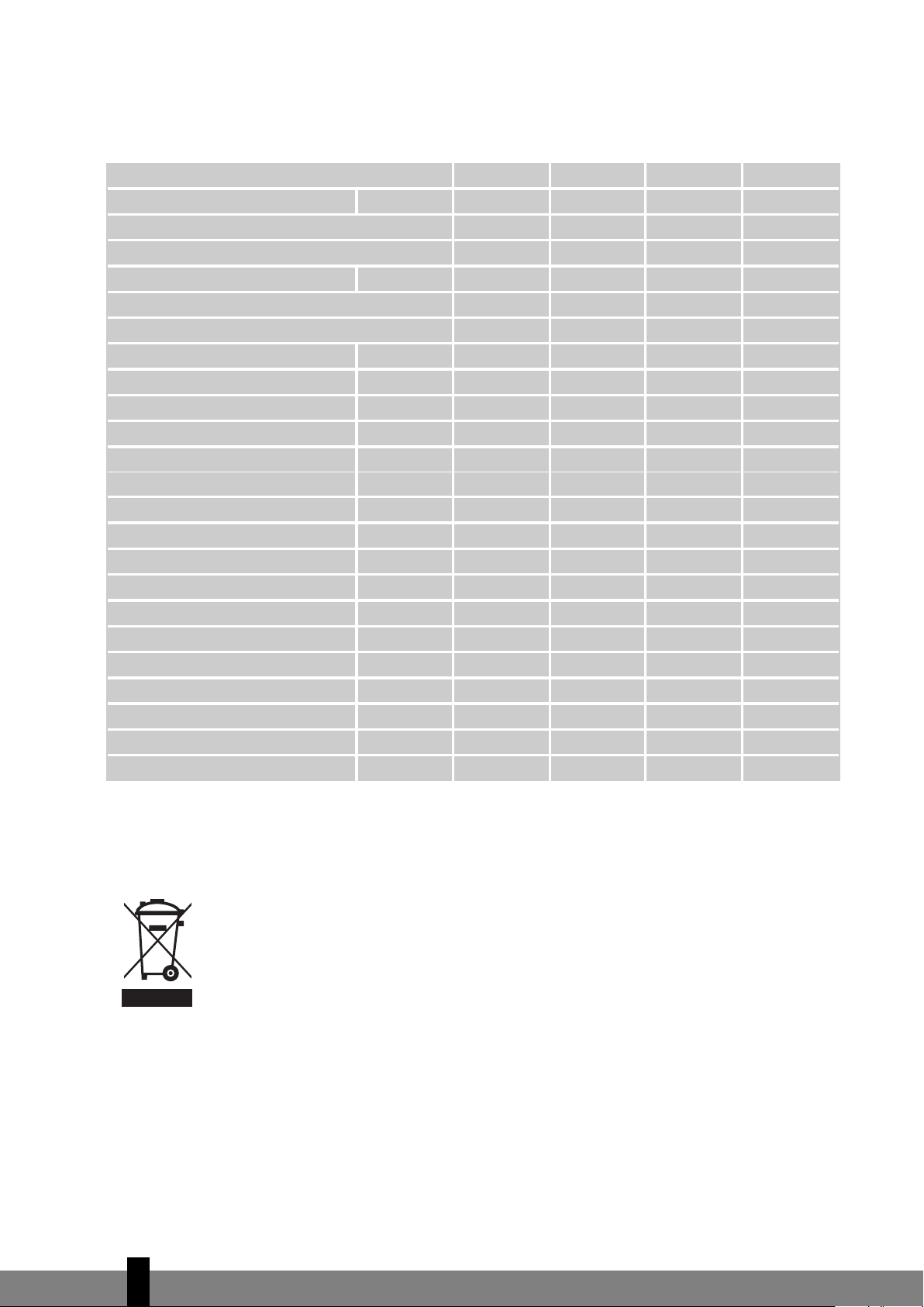
A SPECIFICATIONS
m3/
h
4
80
5
50
7
30
1
000
m
3
9
0
1
10
1
50
2
00
C
OP *
Model
EE Class
EER *
C
OP Class
To be used as indication, subject to modifications.
S95 S125 S185 S245
C
ooling capacity * kW 2.7 3.5 5.3 7.0
D
2
.8 2.8 2.8 2.9
H
eating capacity kW 2.8 3.8 5.7 7.6
D
3
.2 3.2 3.4 3.5
D
ehumidification capacity (max) ** Ltr/day 19 24 36 48
P
ower consumption cooling kW 0.88 1.17 1.9 2.6
P
ower consumption heating kW 0.88 1.17 1.9 2.6
M
ains Volt/Hz/Pf 220-240/50/1 220-240/50/1 220-240/50/1 220-240/50/1
C
urrent (nom) A 3.6 5.1 8.7 12.8
A
irflow (max)
F
or rooms up to
D
imensions indoor unit (WxDxH) mm 718x180x240 770x180x240 1033x202x313 1033x202x313
Dimensions outdoor unit (WxDxH) mm 669x296x506 769x328x552 829x328x552 929x372x652
Weight indoor unit kg 7 7 14 14
Weight outdoor unit kg 24 32 42 56
Refrigerant/charge type/gr R407C/540 R407C/900 R407C/1680 R407C/2300
Noise level indoor unit (max) dB(A) 36 38 43 47
Noise level outdoor unit (max) dB(A) 50 50 60 54
Operating range ºC 10-40 10-40 10-40 10-40
Unit protection indoor IP IP X0 IP X0 IP X0 IP X0
Unit protection outdoor IP IP X4 IP X4 IP X4 IP X4
DDD
DDD
* Conform EN 14511
** Moisture removal at 32°C, 80% RH
Defective electrical devices and batteries must be kept separate from household
waste. Ensure that there is effective recycling where possible. Ask you local
council or dealer for expert advice on recycling.
4
4
Page 5
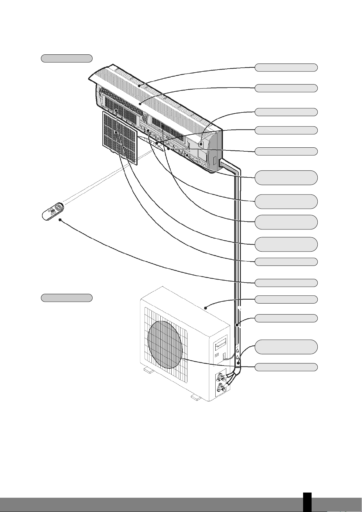
B PARTS
INDOOR UNIT
Air inlet
Front panel
Emergency button
Display
Air outlet
Vertically
adjustable vane
Horizontally
adjustable vane
OUTDOOR UNIT
Active carbon
filter (optional)
Healthy air filter
(optional)
Air filter
Remote control
Air inlet
Drainage hose
Note: Condensation is drained
during COOLING or DR
Pipes and power
cable
Air outlet
YING
The diagrams in these instructions are based on a standard model.
The air conditioner you have pur
chased may be a different model.
4
5
Page 6

C BEFORE USING
Check and adjust the following before using the air conditioner.
Adjusting the remote control
T
he manufacturer has NOT preset the remote control heating or cooling options.
The arrow for ‘Heat’ or ‘Cool’ on the remote control display will flash after the batteries in the remote
control have been replaced.
Depending on the type of air conditioner that you have purchased, the remote control can be adjusted as
follows:
Press any button while the ‘Heat’ arrow is flashing. This sets the heat pump.
Press any button while the ‘Cool’ arrow is flashing. The setting has been entered for cooling only.
If you do not press any button within 10 seconds, the remote control is automatically preset to the heat
pump. Type S95, S125, S185 and S245 are fitted with a heat pump.
The Heat function can NOT be adjusted with the remote control when the remote control has been preset
to Cool Only.
Safety regulations
• Use the correct power supply (see type plate) in order to prevent serious faults, hazards or fire.
• Ensure that the circuit breaker or plug does not become dirty. Connect the plug/circuit breaker to the
power cable correctly. Insufficient contact may cause an electric shock or fire.
• Do not switch the unit off with the circuit breaker or by pulling the plug out of the socket. This may
produce sparks that could start a fire.
• Do not tie any knots in the power cable or pull the power cable. This may damage or break the cable,
causing an electric shock or fire.
• Never insert sticks or any similar object into the unit. The ventilator rotates at high speed and may
cause injury.
• It is detrimental to your health to remain in the cold airstream for an extended period of time. We
recommend that you allow the airstream to flow freely into the room, without obstruction.
• If a fault occurs, switch the machine off with the remote control before pulling the plug out of the
socket.
• Do not carry out any repairs. Incorrect repairs may cause electric shocks, etc.
• Do not place gas burners or ovens in the airstream.
• Do not operate the buttons with wet hands.
• Do not place any objects on the outdoor unit.
• The user is responsible for the earth connection. This must be fitted by a recognised installer in
accordance with local regulations and ordinances.
4
6
Page 7

D INSTALLATION INSTRUCTIONS
Installation diagram
Distance to the wall
must be a minimum
of 50 mm.
Distance to the ceiling must be
a minimum of 50 mm.
istance to the wall must be
D
a minimum of 50 mm.
Distance between
the air inlet and the
wall must be a minimum of 250 mm.
Distance between the air
outlet and the wall must be
a minimum of 500 mm.
- The diagram above is a simplified illustration of the unit and may differ from the unit that
you have purchased.
G
- The installation must be carried out by a recognised installer and connected in accordance
with national regulations.
Distance between the air
inlet and the wall must be
a minimum of 250 mm.
min. 250 mm.
4
7
Page 8

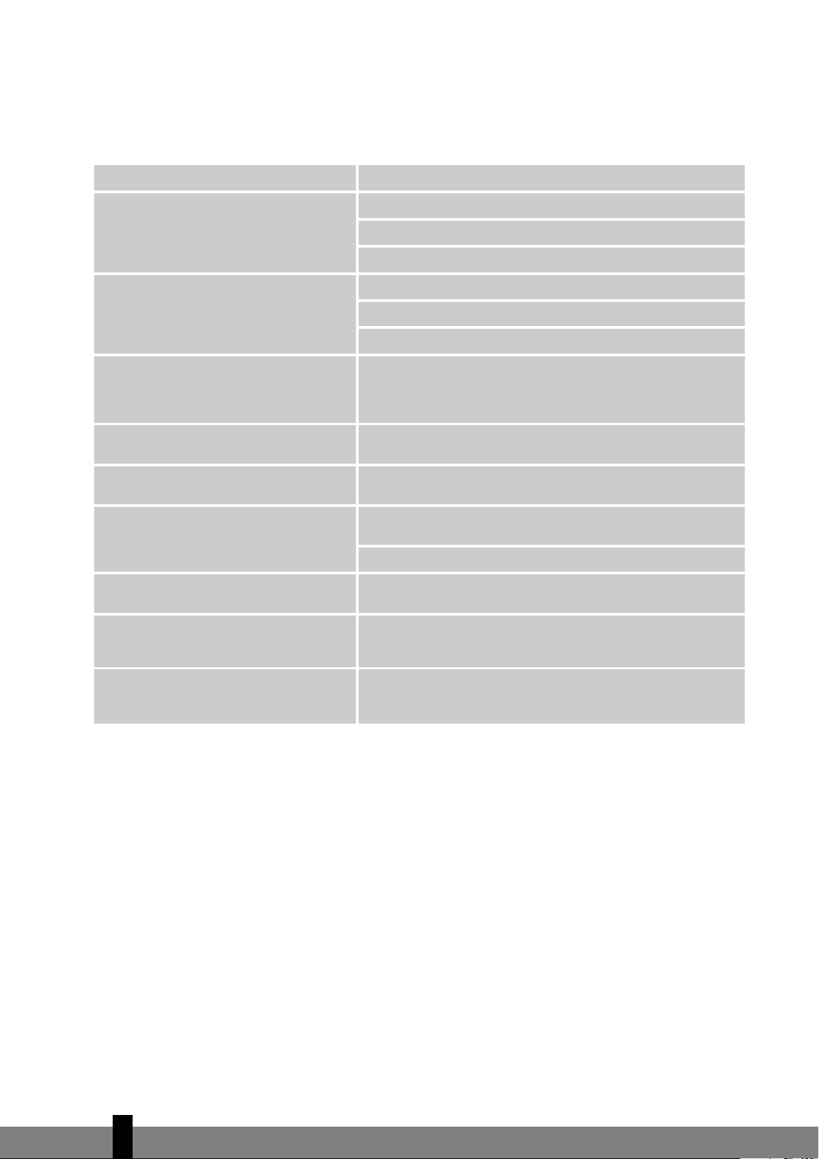
Connecting the power cable
Wiring between the indoor and outdoor unit:
1. Remove the plastic cover from the indoor unit.
2. Use the circuit diagram (attached to the indoor unit) as
a reference for the connections.
3
. Replace the cover, “B” on the outside.
Select the correct location
No obstacles in the vicinity of the air outlet. The air stream
must be allowed to reach the entire room unhindered.
It must be possible to install the pipes and drill the hole in
the wall at an accessible location.
Ensure that there is sufficient distance between the unit,
ceiling and wall (refer to Chapter D).
It must be possible to remove the air filter easily.
The unit and remote control must be placed at least 1 metre
from televisions, radios, etc.
Strip lights may cause faults. Ensure that there is sufficient
distance.
Do not place any object in the vicinity of the air inlet. The
air intake may not be blocked.
The wall must be strong enough to bear the weight of the
unit. The wall construction may not cause any increase in
noise and vibrations.
Front panel
Connecting
clamp (inside)
Housing
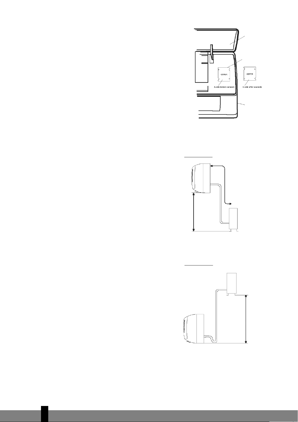
Installation diagram
Indoor unit
Not higher
than 5 m
Outdoor unit
Location for the installation of the outdoor unit
In an accessible, well ventilated location. Do not mount at
potentially hazardous locations, e.g. where there is a danger of a gas leak.
Maintain the required distance from the wall.
Do not expose the outdoor unit to greasy dirt or salty sea
air. Do not mount in the vicinity of gas pipes.
Do not mount on the street side due to the risk of water
splashing onto the unit.
Mount on a fixed foundation in order to prevent excessive
noise.
The air outlet must not be obstructed.
10 m (S95) or a
max. of 15 m
Max. length of
Outdoor unit
Not higher than
5 m
Indoor unit
(S125, S185, S245).
Max. length of 10 m
(S95) or a max. of
15 m (S125, S185,
S245).
4
8
Page 9

INSTALLATION OF THE INDOOR UNIT
1. Installing the mounting plate
- Fit the mounting plate at the location
where the indoor unit will be hung. Take
a
ccount of the direction of the pipes.
- Place the mounting plate horizontally with
the aid of a level indicator or plumb line.
- Drill holes with a depth of 32 mm in order
to mount the plate.
- Insert the plastic plugs into the holes and
screw the plate into position with selftapping screws.
- Check that the mounting plate is firmly in
position and drill the hole for the pipes.
Note: the shape of the mounting plate may differ per model. However, the installation method is the same.
2. Drilling a hole for wires/pipes
- Determine the position of the lead-through hole for the wires/pipes on the basis of the drilling hole in
the mounting plate.
- Drill the hole in the wall. The hole must slope a little to the outside.
- Place a pipe sleeve in the hole in order to protect the wall.
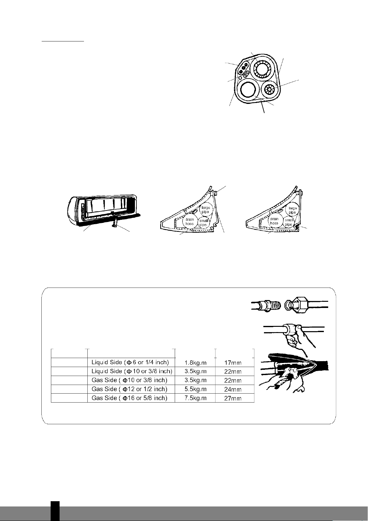
3. Indoor unit wire/pipe installation
- Insert he wires/pipes (gas and liquid
pipes) through the hole from the
outside, or from the inside if you
have installed the indoor unit first.
- Create a recess that corresponds with
the direction of the pipes.
Note: create recess 1, 2 or 4, depending on the position you have chosen for the hole in the indoor unit.
- Fit the drainage hose after connecting the wires/pipes. Now connect the power cables. Finish by
insulating the pipes, cables and drainage hose.
Insulation of the pipe connections:
them in vinyl tape.
Insulate the connection pieces with insulating material and then wrap
4
9
Page 10
P
ipe insulation:
a. Place the drainage hose under the pipe.
b. Use insulating material exceeding 6 mm in
Power cable
Large pipe
Insulating pipe
thickness.
mall
- The drainage hose must slope downwards
s
lightly in order to allow moisture to drain
Power cable 1
heat pump)
(
S
pipe
away easily.
Ensure that the drainage hose is not
twisted and does not protrude. The end
iring of defrosting
W
regulator (heat pump)
Tape
rainage hose
D
may not hang in the water.
If the drainage hose is extended with a hose, the section running alongside the indoor unit must be
insulated.
- If the wire/pipes are on the right hand side, the wires/pipes, power cable and drainage hose must be
insulated and fastened to the back of the indoor unit with a pipe clamp.
A. Fasten the pipe clamp to the groove.
Mounting plate
Pipe clamp
Mounting plate
Pipe clamp
B. Press the clamp to attach it to the mounting plate.
Connecting the pipes
a. Connect the indoor unit pipes with two nut spanners. Select the
correct tightening moment in order to prevent the pipes, connecting pieces and nuts from being deformed or damaged.
b. First tighten by hand, and then with nut spanners.
ightening
Model
S95/S125/S185
S245
S95
S125/S185
S245
Pipe dimensions
T
moment
Push through
here
Mounting plate
Nut
size
Hook here
4
10
Page 11

4
. Connecting the cable
- Indoor unit
Connect the power cable to the indoor unit by connecting
the cables to the units to the clamps on the terminal board
in the correct sequence. The colours of the wires and the
r
eference on the clamps must correspond.
Note: In some models, the cover must be removed in order
to connect the wiring.
- Outdoor unit
1. Remove the access cover of the unit by loosening the
screw. Connect the wires to the clamps on the terminal
board in the following manner:
2. Connect the power cable to the terminal board.
3. Replace the cover and tighten the screw.
4. Place an approved circuit breaker between the power
source and the unit for model S245. Install a suitable
main switch.
Front panel
Indoor unit
Outdoor unit
Terminal board
(inside)
Base plate
Housing
Access cover for
terminal board
(inside)
The illustrations are based on standard models.
The air conditioner you have purchased may be a different model.
Warning:
1. Always connect the air conditioner to a separate power circuit. Refer to the diagram on the inside of
the access cover for the connection of the wires.
2. Check that the cable thickness conforms to regulations (see table below).
3. Check that all wiring is securely connected.
4. Install an earth leak switch.
Note: All cables used must be approved in accordance with local regulations.
Cable specifications
Power cable Power cable connection
Type Cross-section Type Cross-section Type Cross-section
S95
S125
S185
S245
Power cable connection 1 (heat pump)
4
11
Page 12
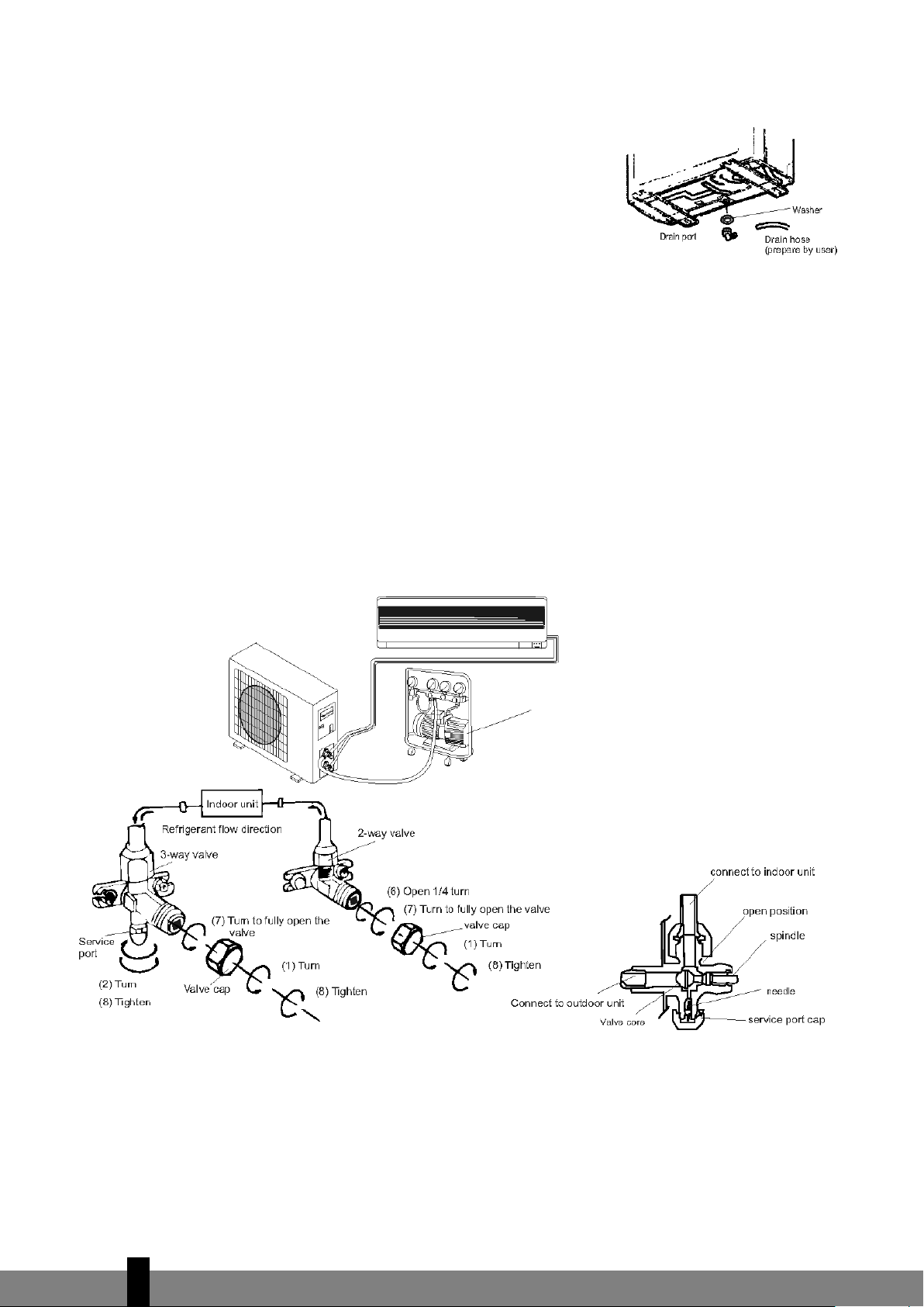
OUTDOOR UNIT INSTALLATION
1. Fit the drainage outlet and drainage hose (only for models with a
heat pump).
Condensation will drip off the outdoor unit when the indoor unit
i
s operating in Heating mode. Fit a drainage outlet and a drainage
hose in order to drain the water effectively. Fit the drainage outlet
and rubber washer to the base plate of the outdoor unit (see fig.).
2. Installing and fitting the outdoor unit
Bolt the unit to a level and solid base.
Ensure that the unit is mounted securely in order to prevent problems caused by strong wind and
vibrations.
3. Connecting the outdoor unit pipes
Remove the covers of the two-way and three-way valve.
Close the pipes separately with the appropriate tightening moment.
4. Outdoor unit cable connection (see previous page)
Purging the pipe system
Air and moisture that remain in the pipe system after installation can damage the compressor. After the
indoor and outdoor units have been connected, air and moisture must be removed with the aid of a vacuum
pump (see below).
Vacuum pump
Three-way valve diagram
4
12
Page 13

1
. Unscrew the two-way and three-way valve and remove the covers.
2. Unscrew the supply pipe and remove the cover.
3. Connect the flexible hose of the vacuum pump to the supply pipe.
4. Allow the vacuum pump to operate for 10-15 minutes until a pressure of 10 mmHg absolute is
achieved.
5
. Close the low-pressure button on the vacuum pump while the pump is still operating. Now switch the
pump off.
6. Open the two-way valve (1/4 turn), and close it again after 10 seconds. Check all connections with
liquid soap or an electronic leak detector.
7. Turn the two-way and three-way valves to their operating positions. Disconnect the hose from the
vacuum pump.
8. Replace and tighten all covers.
Note
- Read these instructions for use before commencing installation.
- Make sure that no air remains in the cooling system and that no refrigerant is leaking.
- Testing: switch the air conditioner on after installation and take notes on the operation.
- Fuse of the indoor unit controller for types S95 and S125: 50T, permitted value 3.15 A,T, 250V. For
types S185 and S245: 3.15A, T, 250V.
- The fuse for the unit as a whole must be suitable for maximum power.
- The plug must be easily accessible in order to be able to switch the unit off in case of emergency.
If there is no easy access, a bipolar main switch must be installed at an easily accessible location.
4
13
Page 14

E INSTRUCTIONS FOR USE
Operation and display
POWER INDICATOR
Lights up when power supply is
connected.
SLEEP MODE INDICATOR
Lights up when this function is
ctivated.
a
RECEIVER
Receives the signal from the remote control.
TIME INDICATOR
Lights up during preset time.
OPERATING INDICATOR
Lit when the unit is in operation.
EMERGENCY BUTTON
To operate the
unit if the remote
control is not operational.
EMERGENCY BUTTON
To operate the unit if
the remote control is
not operational.
Adjustment of automatic restart
The machine has been programmed by the manufacturer to restart
automatically.
Following a power cut, the machine will resume operation in the last
selected function.
The shapes and positions of the switches and indicators may differ for
each model. However
, the functions are identical.
4
14
Page 15

Remote control
The remote control transmits signals to the system.
To activate or deactivate the sleep mode.
To select the TIMER function.
To select the operating mode: Feel, Cooling,
Dry, Fan and Heating.
DOWN button (TOO W
To lower the preset room temperature and
SLEEP button
TIMER button
MODE button
ARM button)
reduce time periods.
UP button (TOO COLD button)
To raise your preset room temperature and extend time periods.
FAN SPEED operation button
or the selection of the ventilator speed in the
F
indoor unit: automatic, high, medium and low.
orizontal plate button
H
To adjust the direction of the airstream.
ON/OFF button
For activation and deactivation.
Note: Each mode and the relevant functions will be specified hereafter.
Placing the batteries
Remove the battery cover in the direction of the arrow.
Place the new batteries as indicated (ensure that the positive (+) and negative poles (-) are in the correct
positions. Slide the battery cover back into place.
Note: Use 2 LR03 AAA (1.5 Volt) batteries. Do not use rechargeable batteries. Replace the batteries with new
batteries of the same type (see above) when the display starts to fade.
Storage of the remote control and tips for use
The remote control can be placed in a
wall-mounted holder.
Note: The remote control holder is
optional.
Using the remote control
Point the r
emote control at the receiver on the indoor unit of the
Receiver
air conditioner. The air conditioner can be operated in this manner up to a distance of 7 metres.
4
15
Page 16

OPERATING INSTRUCTIONS
Less than 20 °C
23 °C
FEEL mode operating procedure
The operating mode is selected automatically (HEATING, DRY,
FAN, COOLING), depending on the room temperature at the
t
ime the selection takes place.
With the remote control pointed at the air conditioner.
1. Activation
Press the ON/OFF/RUN button. The RUN indicator on the
indoor unit will light up when the machine receives a signal.
When the unit is not in the FEEL mode.
2. Selecting the FEEL mode
Press the MODE selector button.
Adjust the MODE to the FEEL setting.
The operating mode and temperature are determined by the
indoor temperature.
Indoor temperature Operating mode Desired temperature
Heating for ‘heat pump’ type
Ventilator for ‘cooling only’ type
20 – 26 °C DRY 18 °C
More than 26 °C COOLING 23 °C
3. Temperature adjustment
Press the
When the
g button or the h button.
g button is pressed, the value of the preset temperature increases by 1°C.
The indicator will not change after the temperature has been increased by 2°C.
When the
h button is pressed, the value of the preset temperature is lowered by 1°C.
The indicator will not change after the temperature has been lowered by 2°C.
Note:
It may occur that no air is expelled from the unit while it is in operation.
The unit will not always start operating immediately after the mode has been changed.
TIMER mode
If you program the timer with the TIMER button upon leaving, it will be pleasantly warm when you return
home. Y
ou can deactivate the timer at night if you wish.
4
16
Page 17

ADJUSTING THE TIMER
To activate the air conditioner at the desired time, follow the procedure specified below (the remote
control and air conditioner are switched off):
1. Press the Timer button.
2
. Select the desired mode by pressing the Mode button.
3. Select the desired temperature by pressing the
possible when the ‘cool’ or ‘heat’ mode is selected).
4. Select the ventilator speed (low, medium or high) or automatic mode
(only possible when the Feel, Cool or Heat mode is selected) by pressing
the Fan button.
The ventilator always operates in the Auto mode when the Dry mode is
selected.
5. Select Swing or no Swing by pressing the Swing button.
6. Press the Timer button (‘h’ flashes).
7. Use the
activate (between 0 and 10 hours can be set at every half hour –
between 10 and 24 hours can be set at every hour).
8. Press the Timer button (‘h’ stops flashing) and the preset time appears
in the display.
9. Press the Timer button again to delete the selected data from the memory.
gh button to select the time at which the air conditioner must
gh button (only
Note: If no buttons are pressed during the programming of the timer function, the remote control will
switch off automatically after 10 seconds.
To switch the air conditioner off at the desired time, follow the procedure specified below (the remote
control and air conditioner are switched off):
1. Press the Timer button.
2. Use the
hours can be set at every half hour – between 10 and 24 hours can be set at every hour).
3. Press the Timer button (‘h’ stops flashing), and the preset time will appear in the display.
4. Press the Timer button again to delete the selected data from the memory.
Note: If no buttons are pressed during the programming of the timer function, the remote control will
switch off automatically after 10 seconds.
Note: if ‘h’ is flashing and you press the ON/OFF/RUN button once, the preset temperature will appear in
the display. You can now adjust the temperature with the
display the time, which can now also be adjusted*. If the Timer button is pressed again, the data is stored
and the remaining time (that the air conditioner will be in operation) will appear in the display.
*
Pressing the ON/OFF/RUN button instead of the Timer button deactivates the remote control.
gh button to select the time at which the air conditioner must deactivate (between 0 and 10
gh button. Press the Timer button again to
Note
G
Press the Timer function to check the settings in the display
Check that the TIMER INDICA
TOR on the indoor unit lights up after the timer has been set.
.
4
17
Page 18

F MAINTENANCE
Cleaning the front panel
1 Switch the machine off and remove the plug from the socket.
2 Hold the front panel at position “a” and pull it towards you.
3
Clean with a soft dry cloth.
Use lukewarm water (max. 30˚ C) to remove stubborn dirt.
4 Never use volatile substances, such as benzene, or abrasives to
remove dirt.
5 Never spray water on the indoor unit.
Dangerous! Electric shock!
6 Replace the front panel and close it by pushing position “b” down.
Cleaning the air filter
The air filter must be cleaned regularly.
Follow this procedure:
1. Switch the machine off completely.
- Open the front panel.
- Carefully pull the filter handle towards you.
- Grip the handle and slide the filter out.
2. Clean and replace the air filter.
To remove stubborn dirt, clean the filter in lukewarm water with detergent. After cleaning, allow the
filter to dry completely out of direct sunlight.
3. Close the front panel.
If the air conditioner is operating in an extremely dusty environment, it must be cleaned every two
weeks.
G SAFETY
Operating status
The safety components can detect faults and deactivate the unit in the following cases:
HEATING
The outside temperature is above 24°C
The outside temperature is under -7°C
The room temperature is above 27°C
COOLING
The outside temperature is above 43°C
The r
oom temperature is under 21°C
DRY
The r
oom temperature is under 18°C
4
18
Page 19

Warning
If the air conditioner is operating in the COOLING or DRY mode while relative humidity is over
G
Noise
- Install the air conditioner on a solid base in order to prevent excessive noise.
- Install the outdoor unit in such a way that the expelled air does not cause a nuisance for neighbours.
- Do not place obstacles in the path of the air expelled from the outdoor unit, this increases noise.
Safety features
1 The safety feature deactivates the unit in the following cases:
2. Press the ON/OFF button to restart after the unit has deactivated due to the operation of the safety
80%, moisture may drip out of the air outlet of the indoor unit (due to a window or door being
open, for instance).
- When the function is stopped or changed while the unit is operating. Wait 3 minutes before
switching the air conditioner on again.
- After the plug has been inserted in the socket and the unit has been immediately switched on. The
unit will activate after approximately 20 seconds.
feature. The Timer must then be reset.
Checks
The following must be checked after the air conditioner has been in use for an extended period of time:
- Overheating of the power cable and the plug. Can you smell burning?
- Is there more noise or vibration than normal?
- Does the indoor unit leak water?
- Is the metal housing live?
Switch the air conditioner off in all the above cases! We recommend periodic inspection by a registered
installer (at least once every five years).
Feature of the HEATING mode
For heating
When the HEATING function is activated, the airstream will only start to flow from the indoor unit after
2 – 5 minutes.
After Heating
When the Heating function is deactivated, the ventilator of the indoor unit will continue operating for
another 2 – 5 minutes.
Defr
osting
During HEATING, the machine will defrost automatically in order to ensure optimum operating efficiency.
This procedure usually takes 2-10 minutes. The ventilator function stops during defrosting. The HEATING
function r
estarts automatically after defrosting.
4
19
Page 20
H PROBLEM SOLVING
Problem Cause / Solution
The plug is not inserted firmly in the socket.
The batteries in the remote control are empty.
The safety feature has been activated or the fuse has burnt out.
A
re the air inlets or outlets blocked?
Is the temperature set correctly?
Is the air filter dirty?
No effective operation.
Faults (due to static electricity discharges or disruptions in the
power supply) will prevent the machine from operating correctly.
If this is the case, pull the plug out of the socket, and then reinsert it after 2-3 seconds.
Does not start immediately. Changing the mode during operation: 3 minute delay.
Unusual odour.
Odour may be caused by another source – furniture, cigarettes,
etc. The unit expels air that it has sucked in.
Caused by the refrigerant in the air conditioner: this does not
indicate a fault.
The sound of defrosting in the heating mode.
A creaking sound.
The sound may be caused by the expansion/shrinkage of the front
panel as a consequence of temperature fluctuations.
Mist/moisture is expelled from the air outlet.
Condensation/mist is created when the air temperature in the
room drops significantly due to the fact that cold air is expelled in
the COOLING or DRY mode.
The red compressor indicator flashes
constantly and the ventilator in the indoor
unit ceases to operate.
The unit will switch from the heating mode to the defrosting
mode. The indicator light will go out within 10 minutes and the
unit will return to the heating mode.
No cooled or heated air.
The sound of running water.
The unit does not operate.
The following problems do not always indicate a fault. Please check them before contacting the service
department:
4
20
Page 21

I GUARANTEE CONDITIONS
There is a 24-month guarantee on the air conditioner from the purchase date. Within this period, all
material and manufacturing defects will be repaired free of charge. The following rules will apply:
•
We expressly reject all further claims to damage compensation, including claims relating to secondary
damage.
• Repairing or replacing components within the guarantee period will not extend the guarantee.
• The guarantee is invalidated if any modifications have been made to the machine, non original parts
have been fitted or repairs have been carried out by third parties.
• Components subject to normal wear, such as the filter, are not covered by the guarantee.
• The guarantee is valid exclusively when you present the original, dated and unaltered purchase
invoice.
• The guarantee does not cover damage caused by actions that deviate from the instructions for use or
neglect.
• Shipment costs and the risks associated with shipping the air conditioner or parts thereof will always
be borne by the buyer.
To prevent unnecessary expense, we recommend that you first always consult the instructions for use
carefully. If this does not provide a solution, ask your dealer to repair the air conditioner.
4
21
Page 22

Egregio Signore, Gentile Signora,
Ci congratuliamo con per l’acquisto del condizionatore d’aria. Lei ha acquistato un
prodotto di qualità, che Le offrirà molti anni di comfort, a condizione che venga usato in
modo responsabile. Per una durata ottimale del condizionatore d’aria La invitiamo a
leggere le istruzioni d’uso. A nome del fabbricante Le offriamo 24 mesi di garanzia per
tutti i danni imputabili alla produzione o al materiale.
Le auguriamo molta freschezza e comfort.
Cordiali saluti,
PVG International b.v.
Reparto Assistenza Clienti
1. LEGGERE DAPPRIMA LE ISTRUZIONI D’USO
2. IN CASO DI DUBBIO, RIVOLGERSI AL RIVENDITORE
>
22
Page 23

CONTENUTO
A Specifiche pagina 24
B Componenti pagina 25
C Operazioni preliminari pagina 26
D Istruzioni per l’installazione pagina 27
E Istruzioni d’uso pagina 34
F Manutenzione pagina 38
G Sicurezza pagina 38
H Risoluzione dei problemi pagina 40
I Condizioni della garanzia pagina 41
>
23
Page 24

A SPECIFICHE
m3/
h
480 550 730 1000
m
3
90 110 150 200
C
OP *
Modello
E
E Class
E
ER *
COP Class
I valori riportati sono indicativi, dati soggetti a modifiche
S95 S125 S185 S245
a. di raffreddamento* kW 2,7 3,5 5,3 7,0
C
DDDD
2,8 2,8 2,8 2,9
apacità di riscaldamento kW 2,8 3,8 5,7 7,6
C
D
,2 3,2 3,4 3,5
3
eumidificazione (max) ** L/24 h 19 24 36 48
D
Assorbimento energia in raffreddamento kW 0,88 1,17 1,9 2,6
Assorbimento energia in riscaldamento kW 0,88 1,17 1,9 2,6
Alimentazione Volt/Hz/Pf 220-240/50/1 220-240/50/1 220-240/50/1 220-240/50/1
orrente (nom) A 3,6 5,1 8,7 12,8
C
Flusso aria (max)
Ideale per ambienti fino a
Dimensioni unità interna (PxLxH) mm 718x180x240 770x180x240 1033x202x313 1033x202x313
Dimensioni unità esterna (PxLxH) mm 669x296x506 769x328x552 829x328x552 929x372x652
Peso unità interna kg 7 7 14 14
Peso unità esterna kg 24 32 42 56
Refrigerante gr R407C/540 R407C/900 R407C/1680 R407C/2300
Livello di rumore unità interna (max) dB(A) 36 38 43 47
Livello di rumore unità esterna (max) dB(A) 50 50 60 54
Temperatura di esercizio ºC 10-40 10-40 10-40 10-40
Protezione unità interna IP IP X0 IP X0 IP X0 IP X0
Protezione unità esterna IP IP X4 IP X4 IP X4 IP X4
DDD
* Conforme a EN 14511
** Tasso di humidità relativa pari al 80% ad una temperatura di 32°C
Gli apparecchi elettrici difettosi e le batterie usate non devono essere smaltiti
come rifiuti domestici. Se possibile utilizzarli per il riciclaggio. Eventualmente
informarsi presso il proprio comune o il rivenditore locale sulle possibilità di
riciclaggio o di smaltimento ecologico.
>
24
Page 25

B IDENTIFICAZIONE DEI COMPONENTI
UNITÀ INTERNA
Presa d’aria
Quadro frontale
Pulsante di
emergenza
Display
Uscita dell’aria
Regolazione ver-
ticale delle lame
Regolazione oriz-
zontale delle lame
Filtro anti-par-
ticelle di carbon
attivo (optional)
Filtro di sicurez-
za per la tutela della
salute (optional)
UNITÀ ESTERNA
Le figure riportate nel presente manuale si riferiscono a un modello standard.
Il vostr
o condizionatore può essere un modello diverso.
Filtro dell’aria
Telecomando
Presa d’aria
Tubo flessibile di
scarico*
Tubi e cavo di
alimentazione
Uscita dell’aria
* NB: la funzione di scarico dell’aria di condensa è attiva in modalità CONDIZIONAMENTO o DEUMIDIFICAZIONE
>
25
Page 26

C PREPARATIVI PRIMA DELL’USO
Prima di utilizzare il condizionatore d’aria, verificare e impostare i seguenti parametri.
Impostazione del telecomando
I
l telecomando NON è impostato direttamente in fabbrica per utilizzare l’apparecchio come generatore di
aria fredda ad uso condizionamento (condizionatore) o di aria calda ad uso riscaldamento (pompa di
calore). Ad ogni sostituzione delle batterie del telecomando, sul display frontale lampeggerà l’apposita
freccia luminosa “Heat” (“caldo”) o “Cool” (“freddo”).
È possibile impostare il telecomando in funzione del tipo di apparecchio acquistato nel modo seguente:
premere un pulsante qualsiasi quando la freccia luminosa posta sul display frontale lampeggia in
corrispondenza della dicitura “Heat” (“caldo”), viene selezionata la funzione “pompa di calore”.
premere un pulsante qualsiasi quando la freccia luminosa posta sul display frontale lampeggia in
corrispondenza della dicitura“Cool” (“freddo”), viene selezionata la funzione “condizionamento”.
Se non viene premuto alcun pulsante entro 10 secondi, il telecomando viene impostato automaticamente
per la funzione “pompa di calore”. Gli apparecchi S95, S125, S185 e S245 sono dotati di una pompa di
calore.
Impostando il telecomando per utilizzare l’apparecchio solo a fini di condizionamento, NON è possibile
impostare la funzione di riscaldamento con il telecomando.
Precauzioni di sicurezza
• Utilizzare il corretto valore di tensione in funzione di quanto indicato sull’apposita targhetta per
evitare gravi danni all’apparecchio o rischi di incendio.
• Tenere costantemente pulito l’interruttore o la spina di alimentazione. Collegare l’interruttore/spina in
modo saldo e preciso al cavo di alimentazione. Un contatto insufficiente potrebbe essere causa di
elettroshock o incendio.
• Non utilizzare l’interruttore o togliere la spina per spegnere l’apparecchio quando è in funzione. Esiste
il rischio di propagazione di scintille che potrebbero causare un incendio.
• Non torcere, tirare o schiacciare il cavo di alimentazione per evitare rischi di elettroshock o incendio.
• Non inserire oggetti estranei quali bastoni o simili nell’apparecchio. A causa dell’elevata velocità di
rotazione della ventola possono verificarsi incidenti.
• Evitare un’esposizione diretta prolungata al flusso di aria fredda in provenienza dall’apparecchio. Si
consiglia di optare per un flusso diffuso.
• In caso di malfunzionamento, spegnere l’apparecchio con il telecomando prima di togliere la spina
dalla presa di alimentazione
• Non procedere direttamente alla riparazione dell’apparecchio. Riparazioni non eseguite da personale
specializzato possono provocare elettroshock ecc….
• Evitare di dirigere il flusso d’aria verso cucine a gas e stufe.
• Non toccare i pulsanti con le mani bagnate.
•
Non inserire alcun oggetto nell’unità esterna.
• La messa a terra conforme alle leggi o norme locali da parte di un tecnico autorizzato rientra nelle
responsabilità dell’utente.
>
26
Page 27

D ISTRUZIONI PER L’INSTALLAZIONE
Schema di installazione
La distanza dal muro
deve essere superiore
a 50 mm.
La distanza dal soffitto deve
essere superiore a 50 mm.
a distanza dal muro deve
L
essere superiore a 50 mm.
La distanza tra il
bocchettone di
uscita dell’aria e
il muro deve
essere superiore
a 250 mm.
La distanza tra il bocchettone
di uscita dell’aria e il muro deve
essere superiore a 500 mm.
- La figura sovrastante è una presentazione semplificata dell’apparecchio, che potrebbe
differire rispetto al prodotto da voi acquistato.
G
- L’installazione deve essere eseguita esclusivamente da personale autorizzato nel rispetto
delle normative nazionali.
La distanza tra il bocchettone di
uscita dell’aria e il muro deve
e superior
esser
minimo 250 mm.
e a 250 mm.
>
27
Page 28
Collegamento del cavo di alimentazione
Connessione tra l’unità interna e l’unità esterna
1. Rimuovere il rivestimento in plastica dell’unità interna.
2. Per il collegamento far riferimento al diagramma dei
cablaggi (allegato all’unità interna).
3
. Ricollocare il rivestimento in plastica. Verificare che il
lato “B” sia all’esterno.
Scegliere la migliore collocazione per l’apparecchio.
Non collocare alcun ostacolo nei pressi del bocchettone di
uscita dell’aria in modo tale che l’aria sia libera di circolare
in ogni punto della stanza.
I tubi e il foro da praticare nel muro devono essere in
posizioni accessibili.
Predisporre uno spazio adeguato dall’apparecchio al
soffitto e al muro (cfr. capitolo D).
I filtri dell’aria devono essere facilmente estraibili.
Tenere l’apparecchio e il telecomando a una distanza
minima di 1 m da televisore, radio, ecc.
Le lampade fluorescenti possono causare interferenze.
Tenerle ad adeguata distanza.
Non mettere nulla vicino al bocchettone di uscita dell’aria,
in modo tale da garantire la massima circolazione dell’aria.
Il muro deve essere sufficientemente solido per sostenere il
peso del condizionatore e non contribuire ad aumentare il
rumore e le vibrazioni prodotti durante il funzionamento.
Quadro frontale
Morsetto di collegamento (interno)
Cassa
Schema di installazione
Unità interna
Altezza max.
pari a 5 m.
Unità esterna
Collocazione dell’unità esterna
Collocare l’unità esterna in un punto accessibile e ben
ventilato; non collocarla, per esempio, in un punto che
presenti pericolo di perdite di gas.
Mantenere la corretta distanza dal muro.
L’unità esterna non deve essere esposta ad aria di mare
sporca, grassa o salata o collocata nei pressi di tubi di
scarico.
Non installare lungo una strada per evitare spruzzi di
acqua.
Predisporre una base fissa per evitare l’aumento della
produzione di rumore.
Verificare che l’aria possa circolare liberamente.
dei tubi: 10 metri
Lunghezza max.
Unità esterna
Altezza max.
pari a 5 m.
Unità interna
(S95) o 15 metri
(S125, S185, S245)
tubi: 10 metri (S95)
o 15 metri (S125,
Lunghezza max. dei
S185, S245)
>
28
Page 29

Installazione dell’unità interna
1. Installazione del piano di supporto
- scegliere il punto dove collocare il piano di
supporto dell’unità esterna tenendo conto
d
ella direzione dei tubi;
- disporre il piano di supporto orizzontalmente con l’ausilio di una riga orizzontale
o di una bolla;
- praticare fori di 32 mm di profondità nel
muro per fissare il piano di supporto;
- inserire i tasselli in plastica nei fori e fissare
il piano di supporto con viti a filetto
tagliente;
- verificare che il piano di supporto sia ben fissato. Praticare poi un foro per i tubi.
NB: la forma del piano di supporto varia da modello a modello, ma il metodo di installazione è identico.
2. Praticare un foro per i tubi
- Determinare la posizione del foro per i tubi nel muro in base al foro nel piano di supporto;
- praticare un foro nel muro. Il foro dovrebbe deviare leggermente verso l’esterno;
- inserire un manicotto nel foro per proteggere il muro.
3. Installazione tubi unità interna
- Inserire i tubi (del liquido e del gas) e
i cavi nel buco praticato nel muro
partendo dall’esterno verso l’interno
oppure dall’interno verso l’esterno
qualora sia già stata installata l’unità
interna;
- tagliare il segmento in plastica in funzione della direzione dei tubi.
NB: tagliare il segmento in plastica 1, 2 o 4, in funzione della posizione scelta per il foro nell’unità
interna.
- dopo aver installato i tubi, installare il tubo flessibile di scarico. Dopodiché collegare i cavi di alimentazione. Infine isolare i tubi, i cavi e il tubo flessibile di scarico.
Isolamento ter
applicar
mico giunti tubi. Avvolgere i giunti dei tubi con un materiale isolato termicamente e poi
e del nastro in vinile.
>
29
Page 30

Isolamento termico tubi
a. collocare il tubo flessibile di scarico sotto i
tubi;
utilizzare materiale di isolamento con
b.
spessore maggiore di 6 mm;
-
il tubo flessibile di scarico deve puntare
verso il basso per agevolare lo scarico.
Verificare che il tubo flessibile di scarico
non sia piegato, avvolto su se stesso o
sporgente; non immergerne l’estremità in
Tubo di grandi dimensioni
Cavo di alimentazione
Cavo di alimen-
azione 1 (per
t
ompa di calore)
p
avo per regolazione dello
C
sbrinamento (per pompa
di calore)
Tubo di isolamento termico
ubo di piccole
T
dimensioni
Tubo flessibile
di scarico
astro
N
acqua.
Se il tubo flessibile di scarico è collegato a una prolunga, la parte che passa lungo l’unità interna deve
essere isolata.
- Quando i tubi sono diretti verso destra, i tubi, il cavo di alimentazione e il tubo flessibile di scarico
devono essere isolati e montati sul retro dell’unità interna con un apposito dispositivo di fissaggio.
Inserire
qui
Piano di
supporto
Dispositivo di fissaggio del tubo
Piano di
supporto
Dispositivo di fissaggio del tubo
Piano di
supporto
A. Inserire il dispositivo di fissaggio del tubo nell’alloggiamento
B. Premere per agganciare il dispositivo di fissaggio del tubo al piano di supporto
Vollegamento dei tubi
a. Collegare i tubi dell’unità interna con due chiavi. Prestare parti-
e attenzione alla coppia di ser
colar
tale da evitar
e che i tubi, i giunti e i dadi si defor
raggio consentita, in modo
mino o dan
-
neggino.
b. Stringergli prima con le dita, poi utilizzare le chiavi.
Modello
S95/S125/S185
S245
S95
S125/S185
S245
Dimensione del tubo
Serraggio
Ampiezza
dei dadi
Fissare qui
>
30
Page 31

4
. Collegamento del cavo
- Unità interna
Collegare il cavo di alimentazione all’unità interna connettendo i cavi delle unità nell’ordine corretto ai morsetti posti
sulla morsettiera. I colori dei fili e i riferimenti sui morsetti
d
evono coincidere.
NB: per alcuni modelli è necessario rimuovere la cassa per provvedere al collegamento dei cavi.
Unità esterna
1. rimuovere lo sportello di accesso dall’unità svitando la vite.
Collegare i cavi ai terminali ai morsetti della morsettiera nell’ordine corretto;
2. fissare il cavo di alimentazione alla morsettiera;
3. ricollocare in sede lo sportello di accesso serrando la vite;
4. utilizzare un interruttore adatto al modello S245 tra la fonte
di alimentazione e l’unità. Prevedere anche un dispositivo di
disconnessione.
Quadro frontale
Unità interna
Unità esterna
Morsettiera
(interna)
Telaio
Cassa
Sportello di
accesso per
morsettiera
(interno)
Le figure riportate nel presente manuale si riferiscono a un modello standard.
Il vostro condizionatore potrebbe essere un altro modello.
Attenzione
1.
Allacciare sempre il condizionatore a un circuito di alimentazione distinto. Per quanto concerne il metodo di
cablaggio, far riferimento allo schema collocato sul lato interno dello sportello di accesso alla morsettiera.
2. Verificare che lo spessore del cavo sia conforme alle norme (si veda la tabella che segue).
3. Controleer of alle bedrading goed vastzit. volgt
4. Installare un interruttore di messa a terra
NB: tutti i cavi utilizzati devono essere approvati secondo le norme locali vigenti.
Specifiche cavi
Cavo di alimentazione
Tipo Sezione
trasversale
S95
S125
S185
S245
Collegamento cavo di alimentazione
Tipo Sezione
trasversale
Collegamento cavo di alimentazione 1 (per pompa di calore)
Tipo Sezione
trasversale
>
31
Page 32

INSTALLAZIONE UNITÀ ESTERNA
1. Installare il portello di scarico e il tubo flessibile di scarico (solo per
i modelli dotati di pompa di calore).
Dall’unità esterna defluisce condensa quando è attiva la modalità
r
iscaldamento. Installare un portello di scarico e un tubo flessibile
di scarico per dirigere il flusso di acqua. Montare l’uscita di scarico
e l’anello di fissaggio in gomma al piano dell’unità esterna (si veda
fig).
2. Installare e fissare l’unità esterna
Fissare con bulloni su una superficie piana e solida.
Fissare bene il supporto per evitare oscillazioni dovute a forti vibrazioni o vento.
3. Collegamento tubi unità esterna
Rimuovere i cappucci dalle valvole a due e tre vie.
Collegare i tubi alle valvole a due e tre vie separatamente nel rispetto del serraggio previsto.
4. Collegamento cavo unità esterna (si veda la pagina precedente)
Svuotamento delle tubazioni
L'aria e l'umidità che rimangono nelle tubazioni dopo l'installazione possono provocare danni al compressore. Dopo l'allacciamento dell'unità interna ed esterna, l'aria e l'umidità devono essere eliminate con una
pompa a vuoto.
Pompa a vuoto
Schema valvola a tre vie
>
32
Page 33

1
. Svitare e rimuovere i cappucci della valvole a due e tre vie.
2. Svitare e rimuovere il cappuccio del condotto secondario.
3. Collegare il tubo flessibile della pompa a vuoto al condotto secondario.
4. Avviare la pompa a vuoto e farla funzionare per 10/15 minuti, fino a raggiungere un vuoto di 10 mm
Hg assoluti.
5
. Con la pompa a vuoto ancora in funzionamento, chiudere la manopola di bassa pressione. Arrestare la
pompa.
6. Aprire la valvola a due vie di _ di giro, poi chiuderla dopo 10 secondi. Controllare il serraggio di tutti i
giunti utilizzando sapone liquido o un rilevatore elettronico di perdite.
7. Portare la valvola a due e tre vie in posizione d’esercizio. Scollegare il tubo flessibile della pompa a
vuoto.
8. Ricollocare e serrare tutti i cappucci delle valvole.
NB:
- Si prega di leggere il presente manuale prima di procedere all’installazione.
- Evitare lo stagnamento di aria nel sistema di raffreddamento e la fuoriuscita di refrigerante.
- Test: avviare il condizionatore dopo l’installazione e segnare i dettagli relativi al funzionamento.
- Tipo di fusibile utilizzato sul sistema di controllo dell’unità interna per i modelli S95 e S125: 50 T, a 3.15
A,T,250V. Per i modelli S185 e S245: 3.15A, T, 250V.
- Il fusibile per l'intera unità deve essere adatto alla potenza massima.
- La spina deve essere sempre accessibile in modo tale da poterla staccare subito in caso di emergenza.
Qualora ciò non fosse possibile, collegare l’apparecchio a un interruttore a doppia polarità in posizione
accessibile.
>
33
Page 34

E ISTRUZIONI D’USO
Operazioni e relative indicazioni sul display
SPIA LUMINOSA DI ALIMENTAZIONE
a spia si illumina quando l’apparecchio è alimentato
L
SPIA LUMINOSA DI FUNZIONE SLEEP
La spia si illumina quando questa funzione è attiva
RICEZIONE SEGNALE
La spia si illumina quando l’apparecchio
riceve un segnale dal telecomando
TIMER
La spia si illumina nell’orario impostato con il timer
FUNZIONAMENTO
La spia si illumina quando l’apparecchio è in funzione
PULSANTE DI
EMERGENZA
Utilizzato per
controllare l’apparecchio quando il
telecomando è
fuori uso
PULSANTE DI
EMERGENZA
Utilizzato per
controllare l’apparecchio quando il
telecomando è
fuori uso
Impostazione funzione “riavvio automatico”
L'apparecchio è programmato dal fabbricante per il riavvio automatico.
Dopo un'interruzione di corrente, l'apparecchio riprende a funzionare in base all'ultima funzione selezionata.
La forma e la posizione degli interruttori e delle spie può variare da
modello a modello, ma le funzioni sono identiche.
>
34
Page 35

Telecomando
Il telecomando invia segnali al sistema.
Per attivar
Per selezionar
mento: Feel, Cooling, Dry, Fan e Heating
Per diminuire la temperatura ambiente
impostata o l’orario nella funzione timer.
e/disattivare la modalità sleep.
Per selezionare la funzione TIMER
e la modalità di funziona-
(pulsante TOO WARM – troppo caldo)
PULSANTE SLEEP
PULSANTE TIMER
PULSANTE MODE
PULSANTE DOWN
PULSANTE UP
(pulsante TOO COOL – troppo freddo)
Per aumentare la temperatura ambiente
impostata o l’orario nella funzione timer.
ULSANTE DI REGOLAZIONE FAN SPEED
P
Per selezionare la velocità del motore della ventola
dell’unità interna: automatica, alta, media e bassa.
PULSANTE DI REGOLAZIONE LAMELLA ORIZZONTALE
Per regolare la direzione del flusso d’aria
PULSANTE ON/OFF
Per accendere e spegnere l’apparecchio
NB: ogni modalità di funzionamento, con le relative funzioni, verrà illustrata ulteriormente nelle pagine seguenti.
Come inserire le batterie
Rimuovere il coperchio delle batterie seguendo la direzione della freccia.
Inserire le batterie nuove come indicato (fare attenzione alla corrispondenza delle polarità + e -).
Ricollocare il coperchio facendo scivolare in posizione.
NB: utilizzare 2 batterie LR03 AAA(1.5 volt). Non utilizzare batterie ricaricabili. Sostituire le batterie esaurite con batterie nuove dello stesso tipo quando il display perde luminosità.
Conservazione e suggerimenti per l’utilizzo del telecomando
Il telecomando può essere collocato a
parete con un apposito porta-teleco-
ta-telecomando
Por
mando
NB: il por
ta-telecomando è optional.
Utilizzo del telecomando
Per utilizzar
verso il dispositivo di ricezione del segnale posto sull’unità interna. In tal modo il telecomando può essere utilizzato fino a una
e il condizionatore d’aria puntare il telecomando
Dispositivo di
ricezione del
segnale
distanza di 7 m.
>
35
Page 36

ISTRUZIONI D’USO
Procedura per il funzionamento in modalità FEEL
La modalità di funzionamento (HEATING, DRY, FAN, COOLING)
viene selezionata automaticamente a seconda della
t
emperatura ambiente.
Puntare il telecomando verso il condizionatore.
1. Accensione
Premere il pulsante ON/OFF/RUN; quando l’apparecchio
riceve il segnale, la spia RUN sull’unità interna si accende.
Quando l’apparecchio non è in modalità FEEL.
2. Selezione della modalità FEEL
Premere il pulsante di selezione della modalità MODE
Selezionare poi la posizione FEEL.
La modalità di funzionamento e la temperatura vengono
determinate in funzione della temperatura interna.
Temperatura interna
Meno di 20 °C
Tra 20°C e 26 °C
Più di 26 °C
3. Impostazione della temperatura
Premere il pulsante
Quando si preme il pulsante g la temperatura sale di 1°C.
Dopo un aumento della temperatura di 2°C, la spia non subisce variazioni.
Quando si preme il pulsante
Dopo una riduzione della temperatura di 2°C, la spia non subisce variazioni.
NB È possibile che quando l’unità è in funzionamento non venga erogata aria. Se la modalità di
funzionamento viene modificata, il sistema potrebbe non provvedere subito alla modifica.
g oppure il pulsante h
Modalità di funzionamento
Riscaldamento, per il modello con pompa
di calore. Ventola per il modello ad
esclusivo uso condizionamento
DRY
COOLING
h, la temperatura scende di 1°C.
Temperatura desiderata
23 °C
18 °C
23 °C
Modalità TIMER
Se prima di uscire lei programma il timer mediante il pulsante TIMER, al suo rientro la casa è piacevolmente calda. Di notte, eventualmente, può disattivar
e il timer.
>
36
Page 37

IMPOSTAZIONE DEL TIMER
Affinché il condizionatore si accenda in corrispondenza dell’orario desiderato, seguire la seguente
procedura (con apparecchio e telecomando spenti):
1
. Premere il pulsante Timer.
2. Scegliere la modalità desiderata premendo il pulsante Mode.
gh
3. Scegliere la temperatura desiderata premendo il pulsante
selezionata la modalità riscaldamento o condizionamento).
4. Scegliere la velocità desiderata della ventola (bassa, media o alta) oppure la
modalità automatica (solo in modalità Feel, Cool o Heat), premendo il
pulsante Fan. In modalità Dry, la ventola funziona sempre alla modalità
automatica.
5. Attivare o meno la modalità Swing premendo il pulsante Swing.
6. Premere il pulsante Timer (‘h’ lampeggia).
gh
7. Utilizzare il pulsante
condizionatore desiderato (tra le 0 e le 10 l’orario può essere impostato per
blocchi di mezz’ora; tra le 10 e le 24, per blocchi di un’ora).
8. Premere il pulsante Timer (‘h’ smette di lampeggiare e sul display viene
visualizzato l’orario impostato per l’accensione del condizionatore).
9. Premere di nuovo il pulsante Timer per cancellare i dati selezionati dalla memoria.
per impostare l’orario di accensione del
(solo con
NB: qualora non venga toccato alcun pulsante in fase di programmazione della funzione timer, il
telecomando si spegne automaticamente dopo 10 secondi.
Affinché il condizionatore si spenga in corrispondenza dell’orario desiderato, seguire la seguente
procedura (con apparecchio e telecomando spenti):
1. Premere il pulsante Timer.
gh
2. Utilizzare il pulsante
e le 10 l’orario può essere impostato per blocchi di mezz’ora; tra le 10 e le 24, per blocchi di un’ora).
3. Premere il pulsante Timer (‘h’ smette di lampeggiare e sul display viene visualizzato l’orario impostato
per lo spegnimento del condizionatore).
4. Premere di nuovo il pulsante Timer per cancellare i dati selezionati dalla memoria.
NB: qualora non venga toccato alcun pulsante in fase di programmazione della funzione timer, il
telecomando si spegne automaticamente dopo 10 secondi.
NB: quando ‘h’ lampeggia e si preme una volta il pulsante ON/OFF/RUN, sul display viene visualizzata la
temperatura impostata. È ora possibile variare la temperatura con il pulsante
pulsante Timer, viene visualizzato di nuovo l’orario, che può essere quindi modificato. * Premendo di
nuovo il pulsante T
accensione del condizionatore).
* Quando, invece di premere il pulsante Timer, si preme il pulsante ON/OFF/RUN, si spegne il telecomando.
per impostare l’orario di spegnimento del condizionatore desiderato (tra le 0
gh
. Premendo il
imer, si memorizzano i dati inseriti e viene visualizzato il tempo rimanente (di
G
NB
Dopo aver impostato il timer, controllare che la spia TIMER INDICATOR sull’unità interna sia
accesa. Premendo il pulsante Timer, vengono visualizzati i valori dell’ultima operazione eseguita.
>
37
Page 38

F MANUTENZIONE
Manutenzione del quadro frontale
1. Spegnere l’apparecchio e togliere la spina dalla presa di alimentazione.
Afferrare il quadro frontale in corrispondenza della posizione “a” e tirarlo
2.
v
erso l’esterno.
3. Pulire con un panno morbido asciutto. Utilizzare acqua tiepida (meno di
30°C) per pulire l’apparecchio nel caso in cui fosse particolarmente sporco.
4. Non utilizzare mai sostanze volatili quali benzina o polveri abrasive per
pulire l’apparecchio.
5. Non spruzzare mai acqua sull’unità interna. Pericolo di elettroshock!
6. Ricollocare in sede il quadro frontale e chiuderlo premendolo verso il basso
in corrispondenza della posizione “b”.
Manutenzione del filtro dell’aria
È necessario pulire il filtro dell’aria regolarmente
Procedere nel modo seguente
1. Spegnere completamente l’apparecchio.
- Aprire il quadro frontale.
- Tirare verso l’esterno la maniglia del filtro con delicatezza.
- Afferrare la maniglia e far scivolare fuori il filtro.
2. Pulire il filtro dell’aria e ricollocarlo in sede.
Qualora fosse particolarmente sporco, lavare il filtro con una soluzione di detergente e acqua tiepida.
Dopo averlo pulito, asciugare il filtro in un punto lontano da fonti di luminosità.
3. Richiudere il quadro frontale. Pulire il filtro dell’aria ogni due settimane se il condizionatore viene
utilizzato in un ambiente particolarmente polveroso.
G SICUREZZA
Condizione di funzionamento
Il dispositivo di sicurezza può rilevare un guasto/errore e arrestare l’apparecchio nei seguenti casi.
Riscaldamento
Temperatura esterna superiore a 24°C
Temperatura esterna inferiore a -7°C
Temperatura ambiente superiore a 27°C
Condizionamento
Temperatura esterna superiore a * 43°C
Temperatura ambiente inferiore a 21°C
Deumidificazione
Temperatura ambiente inferiore a 18°C
>
38
Page 39

Avvertenze
Quando il climatizzatore è programmato sulla funzione COOLING o DRY, in caso di umidità
G
Rumori
- Installare il condizionatore su una superficie solida in modo tale da prevenire la produzione di rumori.
- Installare l’unità esterna in modo tale che il flusso d’aria erogata non arrechi disturbo ai vicini.
- Non collocare alcun ostacolo in corrispondenza del flusso d’aria emesso dall’unità esterna per non
aumentare il numero di decibel prodotti.
Caratteristiche del dispositivo di sicurezza
1. Il dispositivo di sicurezza spegnerà l’apparecchio nei seguenti casi.
2. Dopo un arresto completo dell’unità in seguito all’attivazione della sicurezza, premere il pulsante
dell'aria relativa superiore all'80%, lo scarico dell'aria dell'unità interna può gocciolare (per il
fatto che, ad esempio, sono aperte una finestra o una porta).
- Per riavviare l’apparecchio dopo un arresto o una variazione di modalità è necessario attendere
3 minuti.
- Dopo aver inserito la spina nella presa di corrente e aver attivato l’unità, quest’ultima inizierà a
funzionare dopo circa 20 secondi.
ON/OFF per riavviare.
- Reimpostare il timer.
Controlli
Dopo un uso prolungato del condizionatore, controllare quanto segue:
- Surriscaldamento del cavo e della spina di alimentazione. Si sente odore di bruciato?
- Si sentono rumori o vibrazioni inusuali durante il funzionamento?
- Perdita di acqua dall’unità interna.
- Cassa in metallo sotto tensione.
Qualora si dovesse verificare uno dei casi di cui sopra, spegnere il condizionatore! Si raccomanda
un'ispezione periodica a cura di un installatore riconosciuto (min. 1x 5 anni).
Caratteristiche della modalità HEATING (RISCALDAMENTO)
Pre-riscaldamento
Dopo aver avviato la modalità HEATING, il flusso dell’aria dall’unità interna viene erogato dopo 2/5 minuti.
Post-riscaldamento
Dopo aver spento la funzione di HEATING, il ventilatore continua a girare per altri 2-5 minuti.
Sbrinamento
In modalità RISCALDAMENTO, l’apparecchio provvederà automaticamente allo sbrinamento per aumentare
l’efficienza. La relativa procedura ha una durata compresa tra i 2 e i 10 minuti. Nel corso di tale operazione,
le ventole smettono di funzionar
modalità RISCALDAMENTO.
e. A conclusione dell’operazione, l’apparecchio torna automaticamente in
>
39
Page 40

H RISOLUZIONE DEI PROBLEMI
I seguenti casi non corrispondono necessariamente a un malfunzionamento. Controllare sempre prima di
richiedere un intervento da parte dell’assistenza.
roblema
P
L’apparecchio non funziona
Non viene erogata aria calda o
fredda
Controllo inefficiente
L’apparecchio non parte
immediatamente
Odore strano
Rumore di acqua che scorre
Scricchiolio
Fuoriuscita di nebbiolina/umidità
dal bocchettone dell’aria
e è
La spia r
sempr
dell’unità esterna è ferma.
ossa del compr
e accesa e la ventola
essor
ausa/Solutione
C
Spina non inserita correttamente nella presa
Batterie del telecomando scariche
La protezione si attiva quando il fusibile si è fulminato.
Le prese d’aria e i bocchettoni di fuoriuscita dell’aria sono
bloccati?
La temperatura è stata impostata correttamente?
Il filtro dell’aria è sporco?
Se è presente una forte interferenza (a causa di un’eccessiva
scarica elettrostatica o di tensione di alimentazione non
costante), l’apparecchio non funziona in modo corretto. Quindi,
togliere alimentazione e ricollegare la spina dopo 2/3 secondi.
Variazione della modalità mentre l’apparecchio è in funzione,
tempo di attesa: 3 minuti.
L’odore proviene probabilmente da un’altra fonte quale mobili,
sigarette, ecc… viene aspirato all’interno dell’apparecchio e poi
emesso con l’aria.
Causato dal refrigerante nel condizionatore, non indica un
guasto.
Rumore dovuto alla funzione di sbrinamento in modalità
riscaldamento.
umore può essere generato dall’espansione o dalla
Il r
contrazione del quadro frontale, dovuto alle variazioni di
temperatura.
La nebbiolina/l’umidità si forma quando la temperatura
dell’aria della stanza in cui è collocato il condizionatore si
abbassa a causa dell’aria fr
modalità COOLING (RAFFREDDAMENTO) o DR
(DEUMIDIFICAZIONE).
ecchio passa dalla modalità riscaldamento alla modalità
’appar
L
sbrinamento.
La spia si spegnerà entro dieci minuti, l’unità ripristinerà la
modalità riscaldamento.
edda er
ogata dall’unità inter
YING
na in
>
40
Page 41

I CONDIZIONI DELLA GARANZIA
Il condizionatore d’aria ha una garanzia di 24 mesi dalla data d’acquisto. Entro questo periodo vengono
riparati gratuitamente tutti i difetti di materiale e di fabbricazione. Qui di seguito sono riportate le condizioni della garanzia:
1
. Rifiutiamo esplicitamente tutte le altre richieste di risarcimento, compresi danni conseguenti.
2. La riparazione o la sostituzione di parti entro il termine di garanzia non comporta la proroga della
garanzia stessa.
3. La garanzia non è valida qualora siano state apportate delle modifiche qualora siano state montate
parti non originali o qualora siano state effettuate riparazioni da terzi.
4. Nella garanzia non sono comprese le parti sottoposte a normale usura, quali il filtro.
5. La garanzia vale unicamente dietro presentazione della ricevuta d’acquisto originale datata e qualora
l’apparecchio non sia stato modificato.
6. La garanzia non è valida in caso di danno sorto in seguito ad operazioni che non sono descritte in
questo manuale o in seguito a negligenza.
7. Le spese di spedizione ed i rischi che la spedizione del apparecchio o delle parti comporta sono sempre
a carico dell'acquirente.
Per prevenire costi inutili, si consiglia di consultare dapprima le istruzioni d’uso Qualora nelle istruzioni non
sia presentata la soluzione corretta, rivolgersi al rivenditore di fiducia per la riparazione del condizionatore
d’aria.
>
41
Page 42

Geachte mevrouw, meneer,
Van harte gefeliciteerd met de aankoop van uw airconditioner. U heeft een
kwaliteitsproduct aangeschaft waar u nog vele jaren plezier van zult hebben,
mits u de airconditioner verantwoord gebruikt. Lees daarom eerst deze
gebruiksaanwijzing voor een optimale levensduur van uw airconditioner.
Wij geven u namens de fabrikant 24 maanden garantie op alle optredende
materiaal- en fabricagefouten.
Wij wensen u veel comfort met uw airconditioner.
Met vriendelijke groet,
PVG International B.V.
Afdeling Klantenservice
1. LEES EERST DE GEBRUIKSAANWIJZING.
2. RAADPLEEG BIJ TWIJFEL UW DEALER.
1
42
Page 43

INHOUD
A Specificaties pagina 44
B Onderdelen pagina 45
C Voor ingebruikname pagina 46
D Installatie pagina 47
E Bediening pagina 54
F Onderhoud pagina 58
G Beveiliging pagina 58
H Storingen verhelpen pagina 60
I Garantiebepalingen pagina 61
1
43
Page 44

A SPECIFICATIES
m3/uur
480 550 730 1000
m
3
90 110 150 200
COP *
Model
EE Class
EER *
COP Class
Indicatief gebruiken, wijzigingen voorbehouden
S95 S125 S185 S245
Koelcapaciteit * kW 2,7 3,5 5,3 7,0
DDDD
2,8 2,8 2,8 2,9
Verwarmingscapaciteit * kW 2,8 3,8 5,7 7,6
DDDD
,2 3,2 3,4 3,5
3
Ontvochtigingscapaciteit (max) ** liter/dag 19 24 36 48
Energieverbruik bij koelen kW 0,88 1,17 1,9 2,6
Energieverbuik bij verwarmen kW 0,88 1,17 1,9 2,6
Voeding Volt/Hz/Pf 220-240/50/1 220-240/50/1 220-240/50/1 220-240/50/1
Stroomsterkte (nom) A 3,6 5,1 8,7 12,8
Luchtstroom (max)
Voor ruimtes tot
Afmetingen binnenunit (bxdxh) mm 718x180x240 770x180x240 1033x202x313 1033x202x313
Afmetingen buitenunit (bxdxh) mm 669x296x506 769x328x552 829x328x552 929x372x652
Gewicht binnenunit kg 7 7 14 14
Gewicht buitenunit kg 24 32 42 56
Koudemiddel/hoeveelheid soort/gr R407C/540 R407C/900 R407C/1680 R407C/2300
Geluidsniveau binnenunit (max) dB(A) 36 38 43 47
Geluidsniveau buitenunit (max) dB(A) 50 50 60 54
Werkingstemperatuur ºC 10-40 10-40 10-40 10-40
Beschermingsklasse binnenunit IP IP X0 IP X0 IP X0 IP X0
Beschermingsklasse buitenunit IP IP X4 IP X4 IP X4 IP X4
* Conform EN 14511
** Ontvochtiging bij 32°C, 80% RH
Defecte elektrische apparaten en batterijen horen niet bij het huisafval. Zorg
voor een goede recycling waar mogelijk. Vraag eventueel uw gemeente of uw
lokale handelaar voor een deskundig recycling advies.
1
44
Page 45

B ONDERDELEN
BINNENUNIT
Luchtinlaat
Frontpaneel
Noodknop
Display
Luchtuitlaat
Verticaal afstellen
lamel
Horizontaal
afstellen lamellen
BUITENUNIT
Actief koolstof-
filter (optioneel)
Filter voor gezon-
de lucht (optioneel)
Luchtfilter
Afstandsbediening
Luchtinlaat
Afvoerslang
Opmerking: afvoer condenswater
tijdens KOELEN of DROGEN
Leidingen en
voedingskabel
Luchtuitlaat
De afbeeldingen in deze gebruiksaanwijzing zijn gebaseerd op een standaardmodel.
De door u gekochte air
conditioner kan een ander model hebben.
1
45
Page 46

C VOOR INGEBRUIKNAME
Voor ingebruikname van de airconditioner dient u het volgende te controleren en in te stellen.
Instelling afstandsbediening
D
e afstandsbediening is door de fabrikant NIET ingesteld op de functie alleen koelen of verwarmen, u dient
deze functies zelf in te stellen.
Iedere keer nadat de batterijen van de afstandsbediening zijn vervangen, knippert het pijltje voor “Heat”
of “Cool” op het display van de afstandsbediening.
Afhankelijk van het type airconditioner dat u gekocht hebt, is de afstandsbediening als volgt in te stellen:
Druk op een willekeurige knop als het pijltje voor “Heat” knippert, de warmtepomp is ingesteld.
Druk op een willekeurige knop als het pijltje voor “Cool” knippert, alleen koelen is ingesteld.
Als u niet binnen 10 seconden op een willekeurige knop drukt, wordt de afstandsbediening automatisch op
de warmtepomp ingesteld. Type S95, S125, S185 en S245 zijn uitgerust met een warmtepomp.
Wanneer de afstandsbediening op Alleen Koelen is ingesteld, kan de Verwarmingsfunctie NIET via de
afstandsbediening worden ingesteld.
Veiligheidsvoorschriften
• Gebruik de juiste stroomvoorziening (zie typeplaatje), om ernstige storingen, gevaar of brand te
voorkomen.
• Zorg dat de stroomonderbreker of stekker niet vies wordt. Stekker/stroomonderbreker vakkundig
aansluiten op de voedingskabel, onvoldoende contact kan leiden tot een elektrische schok of brand.
• De unit niet uitzetten met de stroomonderbreker of door de stekker uit het stopcontact te trekken,
dit kan vonken en brand veroorzaken.
• Geen knopen in de voedingskabel leggen of eraan trekken, de kabel kan beschadigen of breken en
een elektrische schok of brand veroorzaken.
• Nooit een stok of iets vergelijkbaars in de unit steken. De ventilator draait op hoge snelheid rond en
kan verwondingen veroorzaken.
• Het is slecht voor uw gezondheid als de koude luchtstroom voor langere tijd op u gericht is. Het
wordt aangeraden de luchtstroom vrij te laten uitstromen in de ruimte.
• Schakel bij storingen het apparaat uit met de afstandsbediening, voor u de stekker uit het stopcon-
tact haalt.
• Voer zelf geen reparaties uit. Verkeerd uitgevoerde reparaties kunnen een elektrische schok, etc.
veroorzaken.
• Gasfornuizen en ovens niet in de luchtstroom plaatsen.
• De knoppen niet met natte handen bedienen.
• Geen objecten op de buitenunit plaatsen.
• De gebruiker is verantwoordelijk voor de aardaansluiting, uit te voeren door een erkende installateur
overeenkomstig plaatselijke voorschriften en bepalingen.
1
46
Page 47

D INSTALLATIE
Installatieschema
Afstand tot de muur
moet minimaal 50
mm zijn.
Afstand tot het plafond moet
minimaal 50 mm zijn.
fstand tot de muur moet
A
minimaal 50 mm zijn.
Afstand tussen
luchtinlaat en
muur moet mini-
maal 250 mm zijn.
Afstand tussen luchtuit
laat en muur moet minimaal 500 mm zijn.
- Bovenstaande afbeelding is een vereenvoudigde weergave van de unit en kan afwijken
van de unit die u gekocht heeft.
G
- De installatie moet uitgevoerd worden door een erkende installateur en aangelegd
overeenkomstig nationale voorschriften.
Afstand tussen luchtinlaat en muur moet
minimaal 250 mm zijn.
-
minimaal 250 mm.
1
47
Page 48

Aansluiting voedingskabel
Bedrading tussen binnen- en buitenunit:
1. Verwijder de kunststof kap van de binnenunit
2. Gebruik het bedradingsschema (gehecht aan de
binnenunit) als referentie voor aansluiting.
3
. Plaats de kap terug, “B” aan de buitenkant.
Kies de juiste locatie
Geen obstakels in de buurt van de luchtuitlaat, zodat de
luchtstroom ongehinderd de gehele ruimte bereikt.
De leidingen en het gat in de muur moeten op een toegankelijke plaats aangebracht kunnen worden.
Zorg voor voldoende afstand tussen unit, plafond en muur
(zie hoofdstuk D).
De luchtfilters moeten gemakkelijk verwijderd kunnen worden.
De unit en afstandsbediening minstens op 1 meter afstand
van televisie, radio etc. plaatsen.
TL-lampen kunnen storingen veroorzaken, zorg voor voldoende afstand.
Niets in de buurt van de luchtinlaat zetten, de aangezogen
lucht moet vrij baan hebben.
De muur moet voldoende belastbaar zijn om het gewicht
van de unit te kunnen dragen, de muurconstructie mag
geen geluidstoename en trillingen veroorzaken.
Frontpaneel
Aansluitklem
(binnenkant)
Behuizing
Installatieschema
Binnenunit
Niet hoger
dan 5 meter
Buitenunit
Locatie voor installatie van buitenunit
Op een toegankelijke, goed geventileerde plaats; niet monteren op een plaats waar gevaar voor bv. een gaslek
bestaat.
De vereiste afstand van de muur aanhouden.
De buitenunit niet blootstellen aan vettig vuil of zoute zeelucht, niet monteren in de buurt van gasleidingen.
Niet aan de straatkant monteren i.v.m. risico van opspattend water.
Op een vast fundament installeren om geluidstoename te
voorkomen.
De lucht moet ongehinderd kunnen uitstromen.
Leidingen max.
10 m (S95) of
max. 15 m (S125,
Buitenunit
Niet hoger dan
5 meter
Binnenunit
S185, S245).
Leidingen max. 10 m
(S95) of max. 15 m
(S125, S185, S245).
1
48
Page 49

INSTALLATIE BINNENUNIT
1. Installeren van de montageplaat
- Montageplaat monteren op de plaats waar
de binnenunit komt te hangen, houd
r
ekening met de richting van de leidingen.
- Plaats de montageplaat horizontaal met
behulp van een waterpas of schietlood
- Boor gaten met een diepte van 32 mm om
de plaat vast te zetten.
- De plastic pluggen in de gaten steken en
de plaat met zelftappers vastschroeven.
- Controleer of de montageplaat goed
vastzit en boor het gat voor de leidingen.
Opmerking: de vorm van de montageplaat kan per model verschillen, de installatiemethode is echter
gelijk.
2. Gat boren voor leidingen
- Bepaal de positie van het doorvoergat van de leidingen op de muur aan de hand van het boorgat in de
montageplaat.
- Gat in de muur boren. Het gat moet naar buiten toe wat aflopen.
- Plaats een schuifmof in het gat om de muur te beschermen.
3. Binnenunit leidinginstallatie
- De leidingen (gas- en vloeistofleiding) en kabels van buiten af
door het gat steken of van binnen
naar buiten als u de binnenunit als
eerste heeft geïnstalleerd.
- Maak een uitsparing die overeenkomt met de richting van de
leidingen.
Opmerking: Maak uitsparing 1, 2 of 4, afhankelijk van de door u gekozen positie voor het gat in de
binnenunit.
- Na aansluiting van de leidingen de afvoerslang monteren. Hierna de voedingskabels aansluiten.
Leiding, kabels en afvoerslang vervolgens isoleren.
en van de pijpverbindingen: Verbindingsstukken isoleren met isolatiemateriaal, omwikkelen met
Isoler
vinyltape.
1
49
Page 50

I
solatie leiding:
a. Plaats de afvoerslang onder de leiding.
b. Gebruik meer dan 6 mm dik isolatie-
Voedingskabel
Grote pijp
Isolatieleiding
materiaal.
leine
- De afvoerslang moet licht aflopen om het
v
ocht gemakkelijk af te kunnen voeren.
Voedingskabel 1
warmtepomp)
(
K
pijp
Let op dat de afvoerslang niet gedraaid
ligt, of uitsteekt, het uiteinde mag niet in
het water hangen.
edrading ontdooiregeling
B
(warmtepomp)
ape
T
Afvoerslang
Als de afvoerleiding met een slang wordt
verlengd dient het gedeelte dat langs de binnenunit loopt te worden geïsoleerd.
- Wanneer de leidingen aan de rechterkant zitten, dienen leiding, voedingskabel en afvoerleiding
geïsoleerd te worden en met een pijpenklem aan de achterkant van de binnenunit te worden
gemonteerd.
Hier doorsteken
Montageplaat
Pijpenklem
Montageplaat
A. Pijpenklem op groef aanbrengen.
B. Druk dan de klem vast op de montageplaat.
Verbinden leidingen
a. Verbind de binnenunit leidingen met twee moersleutels.
Kies het juiste aanhaalmoment om te voorkomen dat leiding,
verbindingsstukken en moeren vervormen of beschadigen.
b. Eerst met de hand aandraaien, daarna met moersleutels
vastzetten.
Model
S95/S125/S185
S245
S95
S125/S185
S245
Afmeting leiding
Aanhaal-
moment
Pijpenklem
Grootte
moer
Montageplaat
Hier vasthaken
1
50
Page 51

4
. Aansluiten kabel
- Binnenunit
Sluit de voedingskabel aan op de binnenunit door de kabels
naar de units in de juiste volgorde aan te sluiten op de
klemmen op het klembord. De kleur van de draden en
r
eferentie op de klemmen moeten overeenkomen.
Opmerking: Bij sommige modellen moet de kap verwijderd
worden om de bedrading aan te kunnen sluiten.
- Buitenunit
1. Verwijder de toegangsklep van de unit door de schroef los
te draaien. Sluit de bedrading op de volgende manier aan
op de klemmen op het klembord:
2. Klem de voedingskabel op het klembord.
3. De klep terugplaatsen en vastschroeven.
4. Plaats een goedgekeurde stroomonderbreker tussen de
voedingsbron en de unit bij het model S245. Installeer een
geschikte hoofdschakelaar.
Frontpaneel
Binnenunit
Buitenunit
Klembord
(binnenkant)
Bodemplaat
Behuizing
Toegangsklep
voor klembord
(binnenkant)
De afbeeldingen zijn gebaseerd op standaardmodellen.
De door u gekochte airconditioner kan een ander model hebben.
Waarschuwing:
1. De airconditioner altijd aansluiten op een apart voedingscircuit. Voor het aansluiten van de bedrading,
zie schema aan de binnenkant van de toegangsklep
2. Controleer of de kabeldikte conform voorschrift is (zie tabel hieronder).
3. Controleer of alle bedrading goed vastzit.
4. Installeer een aardlekschakelaar.
Opmerking: Alle gebruikte kabels dienen goedgekeurd te zijn volgens de lokaal geldende regels.
Specificaties kabels
S95
S125
S185
S245
Voedingskabel Aansluiting voedingskabel
Type Dwarsdoor-
snede
Type Dwarsdoor-
snede
Aansluiting voedingskabel 1 (warmtepomp)
Type Dwarsdoor-
snede
1
51
Page 52

INSTALLATIE BUITENUNIT
1. Monteer afvoeruitgang en afvoerslang (alleen voor modellen met
warmtepomp).
Wanneer de binnenunit op de verwarmingsstand staat, drupt er
c
ondenswater van de buitenunit. Monteer een afvoeruitgang en
een afvoerslang om het water probleemloos af te voeren.
Monteer de afvoeruitgang en rubberen sluitring op de
bodemplaat van de buitenunit (zie afbeelding).
2. Installeren en monteren buitenunit.
Bevestig de unit met bouten op een vlakke en stevige ondergrond.
Monteer de unit extra stevig met het oog op sterke wind en trillingen.
3. Aansluiten leidingen buitenunit
Verwijder de kapjes van de twee- en driewegklep.
Sluit de leidingen apart aan overeenkomstig het draaimoment.
4. Kabelaansluiting buitenunit (zie voorgaande pagina)
Vacumeren leidingsysteem
Lucht en vocht die achterblijven in het leidingsysteem na installatie, kunnen schade veroorzaken aan de
compressor. Na het aansluiten van binnen- en buitenunit, dient lucht en vocht met een vacuümpomp
verwijderd worden, zie hieronder.
Vacuümpomp
Driewegklep schema
1
52
Page 53

1
. De twee- en driewegklep losschroeven en de kapjes verwijderen.
2. De aanvoerleiding losschroeven en het kapje verwijderen.
3. De flexibele slang van de vacuümpomp aansluiten op de aanvoerleiding.
4. De vacuümpomp 10-15 minuten laten draaien tot een druk van 10 mmHg absoluut.
5. De lagedruk knop op de vacuümpomp sluiten terwijl de pomp nog loopt. Hierna de pomp
u
itschakelen.
6. De tweewegklep opendraaien (1/4 slag), na 10 seconden weer dichtdraaien. Controleer alle
verbindingen met vloeibare zeep of een elektronisch lekzoekapparaat.
7. Draai de twee- en driewegklep in gebruikstoestand. Koppel de slang van de vacuümpomp los.
8. Alle kapjes terugplaatsen en vastdraaien.
Opmerking
- Lees eerst deze gebruiksaanwijzing door voor u tot installatie overgaat.
- Zorg dat er geen lucht in het koelsysteem achterblijft en dat er geen koudemiddel lekt.
- Testen: laat de airconditioner na de installatie proefdraaien en noteer gegevens over werking.
- Zekering van de binnenunit controller voor types S95 en S125: 50T, toegestane waarde 3.15 A,T, 250V.
Voor types S185 en S245: 3.15A, T, 250V.
- De zekering voor de totale unit dient geschikt te zijn voor het maximaal vermogen.
- De stekker moet vrij toegankelijk zijn om in noodgevallen de unit meteen uit te kunnen schakelen. Als
er geen vrije toegang is, dient er een dubbelpolige hoofdschakelaar op een gemakkelijk bereikbare
plaats geïnstalleerd te worden.
1
53
Page 54

E BEDIENING
Bediening en display
TROOM INDICATIELAMPJE
S
Licht op wanneer de stroomtoevoer aangesloten is.
SLAAPSTAND INDICATIELAMPJE
Licht op als deze functie actief is.
SIGNAALONTVANGER
Ontvangt signaal van de
afstandsbediening.
TIJD INDICATIELAMPJE
Licht op tijdens ingestelde tijd.
IN BEDRIJF INDICATIELAMPJE
Brandt als unit in bedrijf is.
NOODKNOP
Om de unit te
bedienen als de
afstandsbediening
niet werkt.
NOODKNOP
Om de unit te
bedienen als de
afstandsbediening
niet werkt.
Instellen automatisch herstarten
Het apparaat is door de fabrikant ingesteld op automatisch herstarten.
Na een stroomonderbreking hervat het apparaat zijn werking in de
laatst geselecteerde functie.
Vorm en positie van schakelaars en lampjes kunnen per model verschillen, de functies zijn echter identiek.
1
54
Page 55

Afstandsbediening
De afstandsbediening zendt signalen naar het systeem.
Om slaapstand in te stellen of op te heffen.
oor selecteren TIMER functie.
V
Voor selectie van de bedrijfsmodus:
Feel, Cooling, Dry, Fan en Heating
DOWN KNOP (TE WARM KNOP)
Om ingestelde kamertemperatuur te
verlagen en tijd te verkorten.
SLEEP KNOP
TIMER KNOP
MODE KNOP
UP KNOP (TE KOUD KNOP)
Om ingestelde kamertemperatuur te
verhogen en tijd te verlengen.
FAN SPEED BEDIENINGSKNOP
Voor selectie ventilatorsnelheid binnenunit:
utomatisch, hoog, medium en laag.
a
BEDIENINGSKNOP (HORIZONTAAL LAMEL)
oor instellen richting luchtstroom.
V
ON/OFF KNOP
Voor in- en uitschakelen.
Opmerking: Iedere modus en de relevante functies worden hierna verder gespecificeerd.
Plaatsen van de batterijen
Verwijder de batterijklep in de richting van de pijl.
Plaats nieuwe batterijen zoals aangegeven (let hierbij op de plus- (+) en minpolen (-).
De batterijklep terugschuiven.
Opmerking: gebruik 2 LR03 AAA(1.5volt) batterijen. Geen oplaadbare batterijen gebruiken. Batterijen vervangen door nieuwe van hetzelfde type (zie hierboven) als het display vager wordt.
Opslag van de afstandsbediening
en tips voor gebruik
De afstandsbediening kan in een houder, die aan een muur is bevestigd,
worden geplaatst.
Opmerking: De houder voor afstands
-
bediening is optioneel.
Signaal-
ontvanger
Gebr
uik afstandsbediening
Richt de afstandsbediening op de signaalontvanger op de
binnenunit van de airconditioner. De airconditioner is op deze
manier tot een afstand van 7 meter te bedienen.
1
55
Page 56

BEDIENINGSINSTRUCTIES
Minder dan 20 °C
23 °C
FEEL modus bedrijfsprocedure
De bedrijfsmodus wordt automatisch geselecteerd (HEATING,
DRY, FAN, COOLING) afhankelijk van de kamertemperatuur op
h
et selectiemoment.
Met de afstandsbediening op de airconditioner gericht.
1. Inschakelen
Druk op de ON/OFF/RUN knop. Wanneer het apparaat een
signaal ontvangt licht het RUN indicatielampje van de
binnenunit op.
Als de unit niet op de FEEL modus staat.
2 Selecteren FEEL modus
Druk op de MODE selectieknop
Van MODE op FEEL positie zetten.
Bedrijfsmodus en temperatuur worden bepaald door de
binnentemperatuur.
Binnentemperatuur Bedrijfsmodus Gewenste temperatuur
Verwarmen voor ‘warmtepomp’ type
Ventilator voor ‘alleen koelen’ type
20 – 26 °C DRY 18 °C
Meer dan 26 °C COOLING 23 °C
3. Temperatuur instellen
Druk op de
Als de
g knop of op de h knop.
g knop ingedrukt wordt, wordt de waarde van de ingestelde temperatuur 1°C verhoogd.
Nadat de temperatuur 2°C verhoogd is, verandert het indicatielampje niet.
Als de
h knop ingedrukt wordt, wordt de waarde van de ingestelde temperatuur met 1°C verlaagd.
Nadat de temperatuur 2°C verlaagd is, verandert het indicatielampje niet.
Opmerking:
Het kan voorkomen dat wanneer de unit in bedrijf is er geen lucht uitgeblazen wordt.
Bij verandering van de modus draait de unit niet altijd meteen.
TIMER modus
Wanneer u met de TIMER knop de timer instelt als u weggaat, is het behaaglijk als u weer thuis komt. ‘s
Nachts kunt u de timer eventueel uitschakelen.
1
56
Page 57

INSTELLEN TIMER
Om de airconditioner op het gewenste tijdstip in te schakelen moet de volgende procedure gevolgd
worden (de afstandsbediening en de airconditioner zijn uitgeschakeld):
1. Druk op de Timer knop
2
. Kies de gewenste modus door op de Mode knop te drukken.
3. Kies de gewenste temperatuur door op de
alleen mogelijk wanneer de ‘cool’ of ‘heat’ modus is geselecteerd).
4. Kies ventilatorsnelheid (low, medium of high) of automatische modus
(alleen mogelijk als de Feel, Cool of Heat modus is geselecteerd) door
op de Fan knop te drukken.
In de Dry modus draait de ventilator altijd op Auto modus.
5. Kies Swing of geen Swing door op de Swing knop te drukken.
6. Druk op de Timer knop (‘h’ knippert).
7. Gebruik de
aan moet slaan (tussen 0 en 10 uur kunt u op ieder halfuur instellen;
tussen de 10 en 24 uur kunt u op ieder uur instellen).
8. Druk op de Timer knop (‘h’ stopt met knipperen) en de ingestelde tijd
verschijnt op het display.
9. Druk nogmaals op de Timer knop om de geselecteerde data uit het
geheugen te verwijderen.
gh knop om de tijd te selecteren waarop de airconditioner
gh knop te drukken (is
Opmerking: wanneer er tijdens het programmeren van de timerfunctie geen knoppen worden
ingedrukt, schakelt de afstandsbediening automatisch na 10 seconden uit.
Om de airconditioner op het gewenste tijdstip uit te schakelen moet de volgende procedure gevolgd
worden (de afstandsbediening en de airconditioner zijn uitgeschakeld):
1. Druk op de Timer knop
2. Gebruik de
10 uur kunt u op ieder halfuur instellen; tussen de 10 en 24 uur kunt u op ieder uur instellen).
3. Druk op de Timer knop (‘h’ stopt met knipperen) en de ingestelde tijd verschijnt op het display.
4. Druk nogmaals op de Timer knop om de geselecteerde data uit het geheugen te verwijderen.
Opmerking: wanneer er tijdens het programmeren van de timerfunctie geen knoppen worden
ingedrukt, schakelt de afstandsbediening automatisch na 10 seconden uit.
Opmerking: als ‘h’ knippert en u één keer op de ON/OFF/RUN knop drukt, verschijnt de ingestelde
temperatuur in het display. Nu kunt u de temperatuur wijzigen met de
wordt ingedrukt, verschijnt de tijd weer, die kan nu ook gewijzigd worden*. Als de Timer knop weer wordt
ingedrukt, worden de data opgeslagen en verschijnt de resterende tijd (dat de airconditioner nog in bedrijf is)
in het display
* Wanneer de ON/OFF/RUN knop wordt ingedrukt in plaats van de Timer knop, schakelt de afstandsbediening uit.
gh knop om de tijd te selecteren waarop de airconditioner moet uitschakelen (tussen 0 en
gh knop. Wanneer de Timer knop
.
G
Druk op de T
Opmerking
oleer of het TIMER INDICA
Contr
imer functie om de instellingen op het display te controleren.
TIELAMPJE van de binnenunit oplicht, nadat de timer is ingesteld.
1
57
Page 58

F ONDERHOUD
Schoonmaken frontpaneel
1. Het apparaat uitschakelen en de stekker uit het stopcontact halen.
2. Frontpaneel vastpakken op positie “a” en naar u toetrekken.
3
. Reinigen met een zachte droge doek.
Gebruik handwarm water (max. 30˚ C) om hardnekkig vuil te verwijderen.
4. Gebruik nooit vluchtige stoffen zoals benzine, of een schuurmiddel om vuil
te verwijderen.
5. Nooit water op de binnenunit spuiten.
Gevaarlijk! Elektrische schok!
6. Het frontpaneel terugplaatsen en sluiten door positie “b” naar beneden te
drukken.
Schoonmaken luchtfilter
De luchtfilter dient regelmatig gereinigd te worden.
Handel als volgt:
1. Het apparaat volledig uitschakelen.
- Open het frontpaneel.
- Trek de filterhendel voorzichtig naar u toe.
- Pak de hendel vast en schuif de filter eruit.
2. De luchtfilter reinigen en terugplaatsen.
Bij hardnekkig vuil de filter schoonmaken in handwarm water met afwasmiddel. Na schoonmaken, de
filter op een zonvrije plek volledig laten drogen.
3. Sluit het frontpaneel.
Wanneer de airconditioner in een extreem stoffige ruimte wordt gebruikt, dient deze iedere twee
weken schoongemaakt te worden.
G BEVEILIGING
Bedrijfsconditie
De beveiligingscomponenten kunnen een fout detecteren en de unit uitschakelen in de volgende gevallen:
Verwarmen
De buitentemperatuur is boven de 24°C
De buitentemperatuur is onder de -7°C
De kamertemperatuur is boven de 27°C
Koelen
De buitentemperatuur is boven de 43
De kamertemperatuur is onder de 21°C
Dr
ogen
De kamertemperatuur is onder de 18°C
°C
1
58
Page 59

aarschuwing
W
Wanneer de airconditioner op de COOLING of DRY functie is ingesteld bij een relatieve
G
Geluidsoverlast
- Installeer de airconditioner op een stevige ondergrond om geluidsoverlast te voorkomen.
- Installeer de buitenunit zodanig dat de buren geen geluidshinder ondervinden van de uitgeblazen
- Geen obstakels plaatsen in de baan van de uitstromende lucht van de buitenunit, dit verhoogt de
Kenmerken beveiliging
1 De beveiliging schakelt de unit uit in de volgende gevallen:
2 - Druk nadat de unit gestopt is door het in werking treden van de beveiliging op de ON/OFF knop
l
uchtvochtigheid meer dan 80%, dan kan er vocht uit de luchtuitlaat van de binnenunit
druppelen (doordat bijvoorbeeld een raam of deur open staat).
lucht.
geluidsproductie.
- Na een stop of verandering van functie tijdens werking van de unit, dient u 3 minuten te wachten
voor u de airconditioner opnieuw start.
- Nadat de stekker in het stopcontact gestoken is en de unit meteen ingeschakeld wordt. De unit zal
dan na ca. 20 seconden inschakelen.
voor een herstart.
- De Timer dient opnieuw ingesteld te worden.
Controle
Na langdurig gebruik moet de airconditioner op de volgende zaken gecontroleerd worden:
- Oververhitting van de voedingskabel en stekker. Ruikt u een brandlucht?
- Hoort u meer geluid of is er meer trilling dan normaal?
- De binnenunit lekt water.
- De metalen behuizing staat onder stroom.
Schakel de airconditioner uit in alle bovenstaande gevallen! Periodieke inspectie door een erkend
installateur (min. 1x per 5 jaar) wordt aanbevolen.
Kenmerken van de HEATING modus
Voor verwarmen
Nadat de HEATING functie is opgestart, komt de luchtstroom van de binnenunit pas na 2 – 5 minuten op
gang.
Na verwarmen
Nadat de Heating functie is gestopt, blijft de ventilator van de binnenunit nog 2 – 5 minuten draaien.
Ontdooien
T
ijdens HEATING zal het apparaat automatisch ontdooien voor een optimale werking. Deze procedure
duurt normaal 2-10 minuten. Tijdens het ontdooien stopt de ventilatorfunctie. Na ontdooien start de
HEATING functie weer automatisch op.
1
59
Page 60

H STORINGEN VERHELPEN
Probleem Oorzaak / Oplossing
D
e stekker zit niet goed in het stopcontact.
De batterijen van de afstandsbediening zijn leeg.
De beveiliging is geactiveerd of de zekering is doorgebrand.
Zijn de luchtinlaten, –uitlaten geblokkeerd?
I
s de temperatuur goed ingesteld?
I
s de luchtfilter verontreinigd?
Geen effectieve bediening.
Als gevolg van storing (door ontlading van statische elektriciteit,
storing in stroomvoorziening) zal het apparaat niet goed
functioneren.
Als dat het geval is, de stekker uit het stopcontact halen en na
2-3 seconden weer in het stopcontact steken.
Start niet meteen.
Verandering van de modus tijdens bedrijf: vertraging van 3
minuten.
Vreemde lucht.
Geur is mogelijk afkomstig van een andere bron, meubels
sigaretten, etc. De unit blaast de aangezogen lucht weer uit.
Veroorzaakt door het koudemiddel in de airconditioner,
dit duidt niet op een storing.
Geluid van ontdooien in verwarmingsmodus.
Krakend geluid.
Het geluid kan veroorzaakt worden door uitzetten/krimpen van
het frontpaneel als gevolg van temperatuurswisselingen.
Er komt damp/nevel uit de luchtuitlaat.
Er ontstaat damp/nevel als de lucht in de kamer sterk afkoelt
doordat tijdens de COOLING of DRY werking koude lucht wordt
uitgeblazen.
Het rode compressor indicatorlampje
knippert constant en de ventilator van de
binnenunit werkt niet meer.
De unit gaat van verwarmingsmodus in ontdooimodus.
Het indicatielampje gaat binnen 10 minuten uit, de unit
gaat terug in de verwarmingsmodus.
G
een gekoelde of verwarmde lucht.
Geluid van stromend water.
Unit werkt niet.
1
60
Page 61

I GARANTIEBEPALINGEN
U krijgt op de airconditioner 24 maanden garantie vanaf de aankoopdatum. Binnen deze periode worden
alle materiaal- en fabricagefouten kosteloos verholpen. Hierbij gelden de volgende regels:
1
. Alle verdere aanspreken op schadevergoeding, inclusief gevolgschade wijzen wij uitdrukkelijk af.
2. Reparatie of vervanging van onderdelen binnen de garantietermijn leidt niet tot verlenging van de
garantie.
3. De garantie geldt niet wanneer veranderingen zijn aangebracht, niet-originele onderdelen zijn gemon-
teerd of reparaties zijn verricht door derden.
4. Onderdelen die aan normale slijtage onderhevig zijn, zoals de filter, vallen buiten de garantie.
5. De garantie geldt uitsluitend als u de originele, gedateerde aankoopbon overlegt en als daarop geen
veranderingen zijn aangebracht.
6. De garantie geldt niet bij schade ontstaan door handelingen die afwijken van die in de gebruiksaan-
wijzing of door verwaarlozing.
7. De verzendkosten en het risico van het opsturen van de airconditioner of onderdelen daarvan, komen
altijd voor rekening van de koper.
Om onnodige kosten te voorkomen, raden wij u aan eerst altijd zorgvuldig de gebruiksaanwijzing te
raadplegen. Wanneer deze geen uitkomst biedt, kunt u de airconditoner ter reparatie aanbieden bij uw
dealer.
1
61
Page 62

Szanowni Panstwo,
Serdecznie gratulujemy Panstwu zakupu klimatyzatora. Oprócz chłodzenia powietrza,
klimatyzator ten ma jeszcze inne funkcje, mianowicie: ogrzewanie, odwilżanie i wentylację.
Nabyli Państwo produkt wysokiej jakości, który - przy prawidłowej eksploatacji – będzie
Państwu dobrze służył przez wiele lat. W celu zapewnienia optymalnej jakości pracy
klimatyzatora, prosimy przed pierwszym użyciem aparatu uważnie zapoznać się z niniejszą
instrukcją. Życzymy naszym klientom przyjemnego chłodu i komfortu.
Łączymy serdeczne pozdrowienia,
PVG International b.v.
Dział Obsługi Klientów
1. KLIMATYZATOR DWUSEGMENTOWY
2. INSTRUKCJA OBSŁUGI
:
62
Page 63

SPIS TREŚCI
A Dane techniczne strona 64
B Elementy konstrukcyjne strona 65
Środki bezpieczeństwa strona 66
C
D Instrukcje dot. instalacji strona 67
E Instrukcje dot. eksploatacji strona 74
Konserwacja strona 78
F
G Urządzenie zabezpieczające strona 78
H Wykrywanie usterek strona 80
I Warunki gwarancji strona 81
:
63
Page 64

A DANE TECHNICZNE
m3/h
480 550 730 1000
m
3
9
0
1
10
1
50
2
00
C
OP *
Rodzaj / typ urządzenia
EE Class
EER *
COP Class
Podane wartości są orientacyjne, z zastrzeżeniem zmian
S95 S125 S185 S245
Moc chłodzenie * kW 2,7 3,5 5,3 7,0
DDDD
2,8 2,8 2,8 2,9
Wydajność grzania kW 2,8 3,8 5,7 7,6
D
3,2 3,2 3,4 3,5
suszanie (max) ** L/24h 19 24 36 48
O
Zużycie prądu w czasie chłodzenia kW 0,88 1,17 1,9 2,6
Zużycie prądu w czasie grzania kW 0,88 1,17 1,9 2,6
Napięcie sieci zasilającej V/Hz/Pf 220-240/50/1 220-240/50/1 220-240/50/1 220-240/50/1
użycie energii (nom) A 3,6 5,1 8,7 12,8
Z
Objętość obiegu powietrza (max)
ielkość pomieszczenia
W
Wymiary (głęb. x szer. x wys.) mm 718x180x240 770x180x240 1033x202x313 1033x202x313
Wymiary (głęb. x szer. x wys.) mm 669x296x506 769x328x552 829x328x552 929x372x652
Waga części wewnętrznej kg 7 7 14 14
Waga części zewnętrznej kg 24 32 42 56
Chłodziwo gr R407C/540 R407C/900 R407C/1680 R407C/2300
Poziom hałasu części wewnętrznej dB max. (A) 36 38 43 47
Poziom hałasu części zewnętrznej dB max. (A) 50 50 60 54
Temperatura działania źC 10-40 10-40 10-40 10-40
Klasa bezpieczeństwa jednostki wewnętrznej IP IP X0 IP X0 IP X0 IP X0
Klasa bezpieczeństwa jednostki zewnętrznej IP IP X4 IP X4 IP X4 IP X4
DDD
* Zgodnie z normą EN 14511
** Osuszanie 32˚C, 80% RH.
Zużytych urządzeń elektrycznych oraz baterii nie wolno usuwać wraz z normalnymi
odpadami komunalnymi, ale jeśli jest to możliwe, należy oddać je do utylizacji. W
razie wątpliwości co do możliwości utylizacji należy skontaktować się z lokalnymi
władzami bądź z dealerem.
:
64
Page 65

B ELEMENTY KONSTRUKCYJNE
SEGMENT WEWNÍTRZNY
W
lot powietrza
Płyta frontowa
Przycisk awaryjny
Wyświetlacz
Wylot powietrza
Pionowe płytki
wentylacyjne
Poziome płytki
wentylacyjne
Aktywny filtr
węglowy
(opcjonalnie)
Filtr do
zdrowego powietrza
(opcjonalnie)
SEGMENT ZEWNÍTRZNY
Ilustracje zawarte w niniejszej Instrukcji Obsługi oparte są na modelu standardowym.
T
wój klimatyzator może być innego typu i wyglądać nieco inaczej
Filtr powietrza
Pilot
Wlot powietrza
Przewód
odprowadzający*
Przewody rurowe i
kablowe
Wylot powietrza
* Uwaga: kondensat odpr
owadzany jest podczas CHŁODZENIA lub SUSZENIA
:
65
Page 66

C PRZED PRZYSTĄPIENIEM DO EKSPLOATACJI
Przed przystąpieniem do eksploatacji dokonaj ustawień zgodnie z poniższymi wskazówkami:
Nastawienie pilota
P
ilot NIE jest fabrycznie nastawiony na funkcję, którą klimatyzator ma spełniać - np. czy tylko chłodzenie, czy
tylko ogrzewanie, wybierz więc pożądaną funkcję.
Po każdej wymianie baterii w pilocie, mrugająca strzałka na wyświetlaczu pilota wskazuje “Heat” (Ogrzewanie)
lub “Cool” (Chłodzenie).
Zależnie od typu klimatyzatora, pilota musisz nastawić w następujący sposób:
Naciśnij na dowolny guzik w chwili, kiedy mrugająca strzałka wskazuje “Heat”- klimatyzator nastawiony jest
teraz na funkcję pompy cieplnej.
Naciśnij dowolny guzik w chwili, kiedy mrugająca strzałka wskazuje “Cool” - klimatyzator nastawiony jest teraz
tylko na chłodzenie.
Jeżeli w ciągu 10 sekund nie naciśniesz żadnego guzika, pilot automatycznie wybierze funkcję pompy cieplnej.
W pompę cieplną wyposażone są następujące typy klimatyzatora: S95, S125, S185 i S245.
Kiedy pilot ustawiony jest na funkcję „Tylko Chłodzenie” (Cooling Only), funkcji ogrzewania NIE można
uruchomić za pomocą pilota.
Przepisy bezpieczeństwa
• Na tabliczce typu aparatu podany jest rodzaj prądu, do którego przystosowany jest klimatyzator.
Korzystanie z innego prądu może spowodować usterki, niebezpieczne sytuacje albo pożar.
• Zwróć uwagę, aby automatyczny wyłącznik lub wtyczka się zbytnio nie zabrudził(a). Wyłącznik
automatyczny/ wtyczka musi być fachowo podłączony(a) do kabla, gdyż niezupełne kontaktowanie może
być przyczyną porażenia prądem lub pożaru.
• Nie wyłączaj aparatu za pomocą automatycznego wyłącznika i przez wyciąganie wtyczki z kontaktu. Może
to spowodować iskry, a w rezultacie - pożar.
• Nie zakładaj węzłów na kablu elektrycznym i silnie nie ciągnij za kabel; może on ulec uszkodzeniu lub się
przerwać i spowodować porażenie prądem lub pożar.
• Nigdy nie wtykaj kija itp. przedmiotów do aparatu. Wentylator obraca się z dużą prędkością i może
spowodować porażenia ciała.
• Długotrwale skierowane na ciebie zimne powietrze z klimatyzatora jest szkodliwe dla zdrowia. Strumień
powietrza powinien być skierowany na otwartą przestrzeń pokoju.
• W razie usterki najpierw wyłącz klimatyzator za pomocą pilota, a dopiero potem wyjmij wtyczkę z kontaktu.
• Nie naprawiaj urządzenia sam. Skutkiem nieprawidłowo wykonanej naprawy może być m.in. porażenie
prądem.
• Strumienia powietrza z klimatyzatora nie kieruj na piecyk kuchenny czy jakikolwiek inne źródło ciepła.
• Nie dotykaj przycisków do obsługi aparatu mokrymi rękami.
• Nie kładź nic na zewnętrznym segmencie klimatyzatora.
• Jako użytkownik odpowiedzialny jesteś za uziemienie aparatu. Uziemienie musi być wykonane przez
uprawnionego fachowca, zgodnie z lokalnymi przepisami.
:
66
Page 67

D INSTRUKCJE DOTYCZĄCE INSTALACJI
Schemat instalacji.
Odstęp od ściany musi
wynosić minimalnie
5
cm.
Odstęp od sufitu musi wynosić
m
inimalnie 5 cm.
Odstęp od ściany musi
wynosić minimalnie 5 cm.
Odległość między
wlotem powietrza
a ścianą musi
wynosić
minimalnie 25 cm.
Odległość między wylotem
powietrza a ścianą musi wynosić
minimalnie 50 cm.
Powyższa ilustracja stanowi uproszczony obraz klimatyzatora i może częściowo odbiegać od
klimatyzatora, który nabyłeś.
Instalacja musi zostać przepr
G
obowiązującymi przepisami.
Odległość między wlotem
powietrza a ścianą musi wynosić
minimalnie 25 cm.
minimo 250 mm.
owadzona przez uprawnionego instalatora i wykonana zgodnie z
:
67
Page 68

P
odłączenie kabli elektrycznych.
Przewody między obydwoma segmentami klimatyzatora
(wewnętrznym i zewnętrznym):
1. Podnieś płytę frontową segmentu wewnętrznego.
2. Podłącz kable zgodnie z diagramem podanym na płytce
o
bwodu drukowanego.
3. Dokładnie zamknij płytę (punkty ‘B” po zewnętrznej
stronie).
Wybierz stosowne miejsce
Naprzeciwko wylotu powietrza nie może być żadnych
przedmiotów, które blokują swobodny wypływ strumienia
powietrza na całe pomieszczenie.
Przewody i otwór w murze muszą być umieszczone w
miejscach łatwo dostępnych.
Zwróć uwagę na wymagany odstęp od sufitu i ścian. (zob. rys.).
Dostęp do segmentów nie może być utrudniony, gdyż filtry
powietrza trzeba regularnie wyjmować (patrz rozdział D).
Segment wewnętrzny i pilot muszą się znajdować w odległości
co najmniej 1 metra od odbiornika telewizyjnego, radiowego itp.
Lampy jarzeniowe (świetlówki) mogą powodować zakłócenia,
pamiętaj o wystarczającym odstępie.
Nic nie umieszczaj naprzeciwko wlotu powietrza, wsysane
powietrze musi mieć wolny tor.
Mur musi mieć wystarczającą obciążalność, aby mógł
udźwignąć ciężar poszczególnych segmentów klimatyzatora.
Konstrukcja muru musi być poza tym na tyle solidna, aby nie
powodowała drgań i hałasu.
P
łyta frontowa
Zaciski podłączeń
O
budowa
Schemat instalacji
Segment wewnętrzny klimatyzatora
Nie wyżej niż
5 metrów.
Segment zewnętrzny
Miejsce zainstalowania zewnętrznego segmentu klimatyzatora
Segment zewnętrzny umieść w łatwo dostępnym, dobrze
wentylowanym miejscu; nie umieszczaj go w miejscu, gdzie
istnieje na przykład możliwość ulatniania się gazu.
Zachowaj wymagany odstęp od ściany.
Segment zewnętrzny nie powinien być zamontowany w
miejscu wyeksponowanym na słone powietrze morskie lub
zanieczyszczenia tłustym brudem. Nie umieszczaj go też w
pobliżu wylotu gazów.
W związku z ryzykiem związanym z pryskającą wodą, nie
umieszczaj segmentu od strony ulicy.
Ze względu na poziom głośności, umieść segment na
solidnym, płaskim podłożu.
Odprowadzane powietrze nie może natrafiać na przeszkody
blokujące tor wydmuchu.
maksymalnie 15 metrów w
Długość przewodów rurowych
Segment zewnętrzny
Nie wyżej niż
5 metrów
Segment wewnętrzny.
typach S125, S185 i S245.
10 metrów w typie S95, oraz
może wynosić maksymalnie
.
-
malnie 15 metrów w
typach S125, S185, S245.
typie S95, oraz maksy
Długość przewodów ruro-
symalnie 10 metrów w
wych może wynosić mak-
:
68
Page 69

INSTALACJA SEGMENTU WEWNE˛TRZNEGO
1. Zamocowanie płyty montażowej
- W miejscu, gdzie zawieszony ma być
segment wewnętrzny przytwierdź do ściany
p
łytę montażową, biorąc pod uwagę
kierunek poprowadzenia przewodów
rurowych.
- Przystępując do zamocowania płyty
montażowej skorzystaj z poziomnicy w celu
dokładnego określenia poziomu.
- Wywierć otwory o głębokości 32 mm.
- W otwory wsadź plastikowe korki na śruby
mocujące.
- Sprawdź, czy płyta montażowa jest dobrze umocowana i wywierć otwór na przewody rurowe.
Uwaga: wygląd płyty montażowej może się różnić zależnie od typu aparatu, ale sposób zamocowania jest taki
sam.
2. Wywiercenie otworu na przewody rurowe.
- Miejsce otworu zaznaczone jest na płycie montażowej.
- Wywierć otwór w murze. Wierć tak, aby otwór przechodził przez mur trochę ukośnie w dół (spadek ok. 5
mm).
- Włóż do otworu kołnierz do zabezpieczenia muru.
3. Instalacja przewodów rurowych
segmentu wewnętrznego.
- Przewody rurowe (na gaz i płyn) oraz
kable przeprowadź przez otwór na
zewnątrz, albo odwrotnie, jeśli najpierw
zainstalowałeś zewnętrzny segment
klimatyzatora.
- wytnij otwór na przewody w miejscu
odpowiadającym kierunkowi, w którym
one pójdą.
Uwaga: Zależnie od miejsca, w którym postanowiłeś zrobić otwór w murze, wytnij otwór 1, 2 lub 4 w płycie
montażowej segmentu zewnętrznego.
- Połącz ze sobą poszczególne przewody rurowe i zamontuj wąż odprowadzający. Podłącz następnie kable
elektryczne. Przewody rur
Izolacja cieplna połączeń:
owe, kable i wąż opatrz materiałem izolacyjnym.
Połączenia opatrzyć materiałem izolacyjnym i owinąć taśmą winylową.
:
69
Page 70

Izolowanie przewodów
a. Umieść przewód odprowadzający pod
przewodem rurowym.
Gruby przewód rurowy
Przewód kablowy
I
zolacja cieplna przewodów
b. Należy użyć materiału izolacyjnego o
grubości ponad 6 mm.
-
Przewód odprowadzający musi mieć lekki
spadek żeby odprowadzanie cieczy przebiegało
łatwiej.
Uważaj, żeby przewód nie był przekręcony i
żeby nie wystawał, jego koniec nie może
P
rzewód kablowy
Przewód kablowy
1 (do pompy
c
ieplnej)
Przewód elektryczny regulacji
o
dmrażania (do pompy cieplnej)
Przewód odprowadzający
Taśma
Wąski przewód
r
urowy
wisieć w wodzie.
Jeżeli przewód odprowadzający zostanie przedłużony wężem, część przebiegającą wzdłuż wewnętrznego
segmentu klimatyzatora należy zaizolować.
- Jeżeli przewody są po prawej stronie, to kabel elektryczny i przewód odprowadzający należy owinąć
materiałem izolacyjnym i przymocować klamrą ustalającą z tyłu segmentu wewnętrznego.
utaj
T
wsadzić
Podbudowa
Klamra ustalająca
Podbudowa
Klamra ustalająca
A. Wsadź klamrę ustalającą do rowka.
B. Zahacz klamrę na podbudowie.
Złączenie przewodów rurowych
a. Za pomocą dwóch skrętek rurowych złącz przewody rurowe
segmentu wewnętrznego. Zwróć uwagę na właściwy moment
obrotowy, aby nie przemieścić i nie uszkodzić przewodów i skrętek.
b. Najpierw przykręcić palcami, następnie za pomocą klucza..
yp
T
S95/S125/S185
S245
S95
S125/S185
S245
Wymiary przewodów rurowych
Moment
obrotowy
Wielkość
skrętki
Podbudowa
Tutaj
zahaczyć
:
70
Page 71

4. Podłączenie kabla
- Wewnętrzny segment klimatyzatora
Doprowadź zasilanie do segmentu wewnętrznego kolejno
podłączając za pomocą zacisków przewody, zgodnie z
instrukcją podaną na tabliczce zaciskowej. Zwróć uwagę, aby
k
olory przewodów i zacisków się zgadzały.
Uwaga: W niektórych typach klimatyzatora, aby podłączyć przewody
trzeba zdjąć obudowę.
- Zewnętrzny segment klimatyzatora
1. Odkręć śrubę i zdejmij płytkę zakrywającą. Podłącz przewody
do zacisków na tabliczce zaciskowej.
2. Podłącz na tabliczce kabel zasilania.
3. Umieść z powrotem płytkę zakrywającą i przykręć ją śrubą.
4. W wypadku klimatyzatora typu S245, między źródłem zasilania
a segmentem zamontuj atestowany przerywacz prądu. Zainstaluj
odpowiedni wyłącznik główny.
Rysunki oparte są na modelu standardowym.
Kupiony przez Ciebie klimatyzator może być innego typu.
P
łyta frontowa
Segment
w
ewnętrzny
Segment zew-
nętrzny
Tabliczka zaciskowa
(
wewnątrz)
P
odbudowa
O
budowa
Płytka
zakrywająca i
tabliczka
zaciskowa
(wewnątrz)
UWAGA!
1. Klimatyzator musi być podłączony do osobnego obwodu elektrycznego. Połączenia należy przeprowadzić
zgodnie z diagramem znajdującym się pod płytką zakrywającą.
2. Sprawdź, czy kabel ma odpowiednią grubość (zob. tab. poniżej).
3. Sprawdź, czy wszystkie przewody są dobrze zamocowane.
4. Zainstaluj łącznik uziomowy.
Uwaga: Wszystkie przewody kablowe muszą mieć atesty zgodne z obowiązującymi w kraju przepisami.
Dane techniczne przewodów kablowych
Przewód zasilania Przewód łączący
Typ Średnica Typ Średnica Typ Średnica
S95
S125
S185
S245
Przewód łączący 1 (do pompy cieplnej)
:
71
Page 72

INSTALACJA SEGMENTU ZEWNE˛TRZNEGO
1. Montaż wylotu cieczy i węża odprowadzającego (tylko w typach
klimatyzatora z pompą cieplną).
Kiedy segment wewnętrzny pracuje na funkcji ogrzewania, z aparatu
k
roplami wydala się kondensat. Zamontuj wylot i wąż odprowadzający
w celu bezproblemowego odprowadzenia wody. Zamontuj wylot
odprowadzający i gumową uszczelkę na podbudowie aparatu. (zob.
rys.).
2. Zamontowanie segmentu zewnętrznego
Segment przykręć śrubami do solidnego i płaskiego podłoża.
Ze względu na silne wiatry i drgania, segment musi być bardzo mocno przytwierdzony.
3. Podłączenie przewodów do segmentu zewnętrznego
Zdejmij nasadki z zaworów dwu- i trójdrogowego.
Podłącz kolejno przewody stosując odpowiedni moment obrotowy.
4. Podłączenie przewodu kablowego do segmentu zewnętrznego (zob. na poprzedniej stronie).
Opróżnianie układu
Powietrze i płyn pozostałe w układzie przewodów po instalacji mogą spowodować uszkodzenie kompresora. Po
podłączeniu modułu wewnętrznego i zewnętrznego należy usunąć powietrze i płyn za pomocą pompy próżniowej, patrz niżej.
Pompa próżniowa
Schemat zaworu dwudrogowego
:
72
Page 73

1
. Odkręć dwu- i trójdrogowy zawór i zdejmij z nich nasadki.
2. Odkręć przewód rurowy doprowadzający powietrze i zdejmij nasadkę.
3. Giętki wąż pompy próżniowej podłącz do przewodu doprowadzającego powietrze.
4. Pompa próżniowa powinna pracować przez 10-15 minut, aż osiągnięte zostanie ciśnienie absolutne o
wartości 10 mmHg.
5
. Podczas gdy pompa jeszcze pracuje, zamknij na pompie kurek niskiego ciśnienia, a następnie wyłącz
pompę. .
6. Dwudrogowy zawór odkręć na obrotu i po 10 sekundach znów go zakręć. Za pomocą mydła w płynie lub
aparatu do wykrywania przecieków skontroluj wszystkie połączenia.
7. Zawór dwudrogowy i zawór trzydrogowy odkręć na stan gotowości operacyjnej.
8. Nałóż z powrotem wszystkie nasadki i je dokręć.
Uwaga:
- Przed przystąpieniem do instalacji klimatyzatora przeczytaj uważnie niniejszą instrukcję obsługi.
- Upewnij się, że w systemie chłodzenia nie pozostało powietrze i że nigdzie nie wycieka środek chłodzący.
- Próba: po zainstalowaniu całego urządzenia zrób próbę klimatyzatora; zrób notatki dotyczące pracy
poszczególnych funkcji.
- Bezpiecznik segmentu wewnętrznego dla typów S95 i S125: 50T, dopuszczalna wartość 3,15 A,T, 250V.
Dla typów S185 i S245: 3,15A, T, 250V.
- Bezpiecznik dla całego urządzenia musi być przystosowany do jego maksymalnej mocy.
- W pomieszczeniu musi być łatwy dostęp do wtyczki przewodu zasilania klimatyzatora, aby go w nagłych
wypadkach było można natychmiast wyłączyć. Jeśli dostęp do wtyczki jest utrudniony, w łatwo dostępnym
miejscu należy zainstalować główny wyłącznik dwubiegunowy.
:
73
Page 74

E INSTRUKCJE DOT. EKSPLOATACJI
Obsługa i wyświetlacz
AMPKA KONTROLNA ZASILANIA
L
Świeci się kiedy urządzenie podłączone jest do prądu
AMPKA KONTROLNA STANU SPOCZYNKU (PRZERWY)
L
Świeci się kiedy ta funkcja jest włączona
DBIORNIK SYGNAłU
O
Odbiera sygnały wysyłane z pilota
LAMPKA KONTROLNA CZASOWNIKA
Świeci się podczas zaprogramowanego czasu pracy
LAMPKA KONTROLNA PRACY KLIMATYZATORA
wieci się kiedy aparat pracuje
Ś
PRZYCISK
AWARYJNY
Do obsługi
klimatyzatora kiedy
pilot nie działa.
PRZYCISK
AWARYJNY
Do obsługi
klimatyzatora kiedy
pilot nie działa.
Nastawienie automatycznego uruchomienia wtórnego
Urządzenie jest fabrycznie ustawione na automatyczny restart.
Po awarii zasilania urządzenie wznowi pracę w ostatnio wybranej
funkcji.
Zależnie od typu aparatu, wygląd i rozmieszczenie przycisków i
lampek kontrolnych może się różnić, funkcje są jednak takie same.
:
74
Page 75

Pilot
Pilot wysyła do odbiornika następujące sygnały.
Guzik SLEEP (PRZERWA)
Do włączania i wyłączania przerwy w pracy aparatu.
Guzik TIMER (CZASOWNIK)
Do wybierania funkcji czasownika.
Guzik MODE (FUNKCJA PODSTAWOWA)
Do wybierania funkcji: Feel, Cooling, Dry,
Fan oraz Heating
Guzik DOWN (ZBYT CIEPŁO)
Do obniżania temperatury w pokoju i skrócenia
czasu ogrzewania.
Guzik UP (ZBYT ZIMNO)
Do podwyższania temperatury w pokoju i
przedłużenia czasu ogrzewania.
Guzik obsługi FAN (WENTYLATOR). Do regulowania
obrotów wentylatora w segmencie wewnętrznym:
automatycznie, wysokie, średnie, niskie.
Guzik obsługi POZIOME LAMELE
Do regulacji kierunku strumienia powietrza przez
przestawienie płytek.
Guzik ON/OFF
Do włączania i wyłączania aparatu.
Uwaga: Każda podstawowa funkcja klimatyzatora i poszczególne funkcje drugorzędne opisane są bardziej
szczegółowo w dalszej części Instrukcji.
Włożenie baterii
Pokrywkę obsady baterii wyjmij zgodnie z kierunkiem strzałki.
Włóż nowe baterie zgodnie z oznaczeniami - zwróć uwagę na położenie biegunów plus- (+) i minus (-).
Wsuń z powrotem pokrywkę obsady.
Uwaga: stosuj baterie 2 LR03 AAA (1,5 volt). Nie używaj baterii zdatnych do ładowania. Kiedy wyświetlacz pilota
zaczyna powoli wygasać, wymień baterie na nowe tego samego typu (zob. wyżej).
Przechowywanie pilota i wskazówki
dotyczące użycia
Obsada pilota
Pilota można przechowywać w obsadzie
zamocowanej na ścianie.
Uwaga: Obsada pilota nie należy do
standardowego wyposażenia.
Użycie pilota
Odbiornik
sygnałów
Nakieruj pilota na odbiornik sygnałów w kliematyzatorze. Aparat
można w ten sposób obsługiwać z odległości do 7 metrów.
:
75
Page 76

INSTRUKCJE DOTYCZĄCE EKSPLOATACJI
Funkcja podstawowa feel (czujnik)
Poszczególne funkcje podstawowe (HEATING, DRY, FAN,
COOLING) wybierane są automatycznie, zależnie od tego, jaką
t
emperaturę pomieszczenia czujnik skonstatuje w momencie
wybierania.
Z pilotem nakierowanym na segment wewnętrzny
1. Włączenie klimatyzatora
Wciśnij guzik ON/OFF/RUN. Kiedy aparat odbierze sygnał,
zapali się lampka kontrolna RUN (PRACA) na aparacie.
Jeśli czujnik nie jest włączony:
2. Wybranie czujnika
Wciśnij guzik MODE
Wybierz funkcję FEEL.
Funkcja podstawowa i temperatura określone zostają przez
temperaturę pomieszczenia.
Temperatura pomieszczenia
Meno di 20°C
Tra 20
°C e 26°C
Pi di 26
3. Nastawienie temperatury
Naciśnij guzik
Każdorazowe naciśnięciu guzika
Przy podwyższeniu temperatury o 2o C, lampka kontrolna się nie zmienia.
Każdorazowe naciśnięciu guzika
Przy obniżeniu temperatury o 2o C, lampka kontrolna się nie zmienia.
Uwaga: Może się zdarzyć, że podczas pracy klimatyzatora nie następuje wydmuch powietrza: W wypadku
przejścia na inną funkcję podstawową, aparat nie zawsze reaguje natychmiast.
°C
g lub guzik h.
Funkcje podstawowe
Ogrzewanie w klimatyzatorach typu
„pompa cieplna” . Wentylator w
klimatyzatorach typu „tylko chłodzenie”
DRY (suszenie)
COOLING (chłodzenie)
g powoduje, że wartość programowanej temperatury podnosi się o 1o C.
h powoduje, że wartość programowanej temperatury obniża się o 1o C.
Pożądana temperatura
23°C
18
°C
23°C
FUNKCJA CZASOWNIKA
Za pomocą przycisku TIMER można np. wychodząc z domu zaprogramować włączenie się klimatyzatora, aby po
powrocie mieszkanie było przyjemnie ogrzane. Na noc można ewentualnie wyłączyć timer.
:
76
Page 77

ZAPROGRAMOWANIE CZASOWNIKA
Aby klimatyzator się włączył o określonej godzinie, wykonaj następujące czynności (zarówno pilot, jak i
klimatyzator są wyłączone):
1
. Naciśnij guzik ‘Timer’
2. Za pomocą guzika ‘Mode’ wybierz wymaganą funkcję podstawową.
3. Za pomocą guzika
tylko wówczas, jeśli uprzednio wybrana została funkcja ‘cool’ albo ‘heat’).
4. Za pomocą guzika ‘Fan’ wybierz szybkość obrotów wentylatora (low niskie, medium - średnie lub high - wysokie) albo funkcję automatyczną
((jest to możliwe tylko wówczas, jeśli uprzednio wybrana została funkcja
Feel, Cool albo Heat). Po wybraniu funkcji ‘Dry’ wentylator pracuje na
funkcji ‘Auto’.
5. Guzikiem ‘Swing’ możesz regulować kierunek strumienia powietrza.
6. Wciśnij guzik ‘Timer’ (‘h’ zaczyna mrugać).
7. Za pomocą guzika
(między godz. 0 a 10 zaprogramować można każde wpół i każdą pełną
godzinę, między godz. 10 a 24 tylko każdą pełną godzinę).
8. Wciśnij jeszcze raz guzik ‘Timer’ (‘h’ przestaje mrugać), zaprogramowany
czas ukazuje się w wyświetlaczu.
9. Jeśli zaprogramowane dane chcesz z pamięci pilota wymazać, wciśnij guzik ‘Timer’.
gh wybierz pożądaną temperaturę (jest to możliwe
gh nastaw czas, kiedy klimatyzator ma się włączyć
Uwaga: Jeżeli podczas programowania funkcji czasownika nie wciśniesz żadnego guzika, po 10. sekundach
pilot automatycznie się wyłączy.
Aby klimatyzator się wyłączył o określonej godzinie, musisz wykonać następujące czynności (zarówno pilot, jak i
klimatyzator są wyłączone):
1. Naciśnij guzik ‘Timer’
2. Za pomocą guzika
gramować można każde wpół i każdą pełną godzinę, między godz. 10 a 24 tylko każdą pełną godzinę).
3. Wciśnij guzik ‘Timer’ (‘h’ przestaje mrugać), zaprogramowany czas ukazuje się w wyświetlaczu.
4. Wciśnij jeszcze raz guzik ‘Timer’ jeśli zaprogramowane dane chcesz z pamięci wymazać.
Uwaga: Jeżeli podczas programowania funkcji czasownika nie wciśniesz żadnego guzika, po 10.
sekundach pilot automatycznie się wyłączy.
Uwaga: jeśli jeden raz naciśniesz na guzik ON/OFF/RUN podczas gdy ‘h’ mruga, w wyświetlaczu ukaże się
nastawiona temperatura. Możesz teraz zmienić temperaturę za pomocą guzika
‘Timer’ ukazuje się znów godzina, którą również możesz teraz zmienić*. Ponowne wciśnięcie guzika ‘Timer’
powoduje, że dane zostają zapisane w pamięci, a w wyświetlaczu ukazuje się okres czasu, po którym
klimatyzator się wyłączy.
* Jeżeli zamiast guzika ‘Timer’ wciśniesz guzik ON/OFF/RUN, pilot się wyłączy
gh nastaw czas, kiedy klimatyzator ma się wyłączyć (między godz. 0 a 10. zapro-
gh. Po wciśnięciu guzika
.
G
Uwaga
Sprawdź, czy po zaprogramowaniu czasownika lampka kontrolna TIMER na aparacie się świeci. Jeśli
chcesz na wyświetlaczu sprawdzić zaprogramowane dane, wciśnij guzik ‘Timer’.
:
77
Page 78

F KONSERWACJA
Czyszczenie płyty frontowej
1. Wyłącz aparat i wyjmij wtyczkę z kontaktu.
2. Chwyć płytę frontową w punktach „a” i przyciągnij do siebie.
3
. Wyczyść płytę miękką, suchą ściereczką. Do usunięcia uporczywego brudu
możesz użyć letniej wody (poniżej 30
4. Do czyszczenia nigdy nie używaj mokrych substancji, jak benzyna czy środki
ścierające.
5. Nigdy nie spryskuj aparatu wodą. Jest to niebezpieczne! Grozi porażeniem
prądem!
6. Zamknij płytę naciskając ją w dół w punktach „b”.
Czyszczenie filtra
Filtr powietrza wymaga regularnego czyszczenia.
Postępuj, jak następuje:
1. Całkowicie wyłącz aparat.
- Podnieś płytę frontową.
- Ostrożnie przyciągnij do siebie uchwyt filtra.
- Trzymając za uchwyt wysuń filtr z aparatu.
°C).
2. Wyczyść filtr i włóż go z powrotem.
W wypadku dużego zabrudzenia, wymyj filtr w letniej wodzie z dodatkiem środka do zmywania naczyń. Po
wymyciu filtra poczekaj aż się całkowicie wysuszy w NIE nasłonecznionym miejscu.
3. Zamknij płytę frontową.
Jeżeli klimatyzator pracuje w wyjątkowo zakurzonym pomieszczeniu, filtr należy czyścić co dwa tygodnie.
G URZĄDZENIE ZABEZPIECZAJĄCE
Warunki eksploatacji
Urządzenie zabezpieczające klimatyzatora może wykryć błąd i wyłączyć aparat w poniższych sytuacjach:
OGRZEWANIE
Temperatura na zewnątrz wynosi ponad 24°C
Temperatura na zewnątrz spadła poniżej -7
Temperatura pomieszczenia wynosi ponad 27
CHŁODZENIE
Temperatura na zewnątrz wynosi ponad 43°C
T
emperatura pomieszczenia spadła poniżej 21
°C
°C
°C
SUSZENIE
T
emperatura pomieszczenia spadła poniżej 18
:
78
°C
Page 79

OSTRZEŻENIE
Jeśli klimatyzator jest ustawiony na funkcję COOLING (chłodzenie) lub DRY (osuszanie) przy wilgot-
G
Hałas
- Aby uniknąć wzrostu poziomu głośności, umocuj wewnętrzny segment klimatyzatora na solidnym podłożu.
- Zewnętrzny segment zainstaluj w takim miejscu, aby odgłos wydmuchiwanego powietrza i pracy
- Naprzeciwko wylotu obydwu segmentów nie umieszczaj żadnych przedmiotów, gdyż powoduje to wzrostu
Właściwości urządzenia zabezpieczającego
1. Urządzenie zabezpieczające wyłącza aparat w następujących sytuacjach:
2. Po wyłączeniu klimatyzatora w wyniku zadziałania urządzenia zabezpieczającego, wciśnij guzik ON/OFF,
ności względnej powietrza przekraczającej 80%, z odpływu powietrza modułu wewnętrznego może
kapać woda (przez to, że np. otwarte jest okno lub drzwi).
klimatyzatora nie przeszkadzał sąsiadom.
poziomu głośności.
- Jeśli po zatrzymaniu lub zmianie funkcji podczas pracy klimatyzatora nie odczekasz 3 minut zanim
ponownie włączysz aparat.
- Jeśli klimatyzator podłączysz wtyczką do prądu i natychmiast włączysz aparat. Aparat włączy się po ok.
20. sekundach.
aby spowodować powtórne włączenie.
- Czasownik trzeba w takim wypadku ponownie zaprogramować.
Kontrola
Po długotrwałej pracy klimatyzatora sprawdzić powinieneś następujące rzeczy:
- Ewentualne przegrzanie kabla i wtyczki. Czy czujesz woń spalenizny?
- Czy aparat nie pracuje głośniej albo czy nie zauważasz więcej drgań niż zwykle?
- Czy z segmentu wewnętrznego nie wycieka woda?
- Czy metalowa obudowa nie jest pod napięciem.
W każdej z powyższych sytuacji natychmiast wyłącz klimatyzator! Zalecany jest okresowy przegląd przez
uprawnionego montera (min. 1x na 5 lat).
Właściwości funkcji HEATING
Podgrzewanie wstępne
Po włączeniu fukcji HEATING segment wewnętrzny zaczyna wydmuch ciepłego powietrza po ok. 2- 5 minutach.
Na verwarmen
Po zakończeniu funkcji ogrzewania, wentylator segmentu wewnętrznego pracuje jeszcze przez 2 - 5 minut.
Odmrażanie
Aby praca funkcji HEATING przebiegała optymalnie, aparat automatycznie się odmraża. Proces odmrażania
trwa zwykle 2-10 minut. W trakcie odmrażania przerwana zostaje praca wentylatora. Po odmr
HEATING automatycznie się znów włącza.
ożeniu funkcja
:
79
Page 80

H WYKRYWANIE USTEREK
Poniższe problemy niekoniecznie muszą oznaczać, że zaistniała poważna awaria. Zanim zadzwonisz do punktu
napraw, sprawdź uprzednio:
Problem
Klimatyzator nie pracuje.
Brak schłodzonego lub ogrzanego
powietrza.
Sterowanie funkcjami nie daje efektu.
Aparat nie zaczyna natychmiast
pracować.
Dziwny zapach.
Odgłos przepływającej wody.
Trzaski w aparacie.
Z wylotu powietrza wydobywa się
para.
Czerwona lampka kontrolna
kompresora ciągle się zapala i
wentylator segmentu wewnętrznego
przestał pracować.
Rozwiązanie
Wtyczka nie jest prawidłowo wsadzona do kontaktu.
Baterie pilota się wyczerpały.
Włączone jest zabezpieczenie lub przepalił się bezpiecznik.
Czy wloty / wyloty powietrza są zablokowane?
Czy temperatura jest dobrze nastawiona?
Czy wyczyszczono filtr powietrza?
Drobna usterka (wyładowanie elektryczności statycznej, zakłócenie
w dopływie prądu) może być przyczyną nieprawidłowego działania
klimatyzatora. Wyjmij w takim wypadku wtyczkę z kontaktu i po
2-3 sekundach wsadź ją z powrotem.
Zmiana funkcji podczas pracy klimatyzatora, opóźnienie wynosi 3
minuty.
Woń może pochodzić z innego źródła - mebli, papierosów itd.
Aparat wydmuchuje wessane powietrze.
Spowodowane przez środek chłodzący w klimatyzatorze, nie
wskazuje na usterkę.
Dźwięk towarzyszący odmrażaniu kiedy aparat włączony jest na
funkcję ogrzewania.
Dźwięk może być spowodowany rozprężaniem/ kurczeniem się
płyty frontowej aparatu w wyniku zmian temperatury.
Para wytwarza się jeśli powietrze w pomieszczeniu silnie się
oziębiło ze względu na to, iż podczas działania funkcji COOLING
albo DRY wydmuchiwane jest zimne powietrze.
Aparat przechodzi z funkcji ogrzewania na funkcję odmrażania.
Lampka kontrolna zgaśnie w ciągu 10. minut i aparat przejdzie
znów na funkcję ogrzewania.
:
80
Page 81

I WARUNKI GWARANCJI
Wytwórca udziela na klimatyzator 24. miesięcznej gwarancji, licząc od daty zakupu. W okresie gwarancyjnym
naprawie podlegają wszelkie usterki materiałowe i błędy fabryczne. Obowiązują przy tym następujące zasady:
1
. Producent nie honoruje jakichkolwiek roszczeń o odszkodowanie, w tym roszczeń związanych ze szkodą
wtórną, powstała w wyniku usterki.
2. Naprawa lub wymiana części/podzespołów w okresie gwarancji nie ma wpływu na obowiązujący okres
gwarancji.
3. Gwarancja przepada jeżeli w urządzeniu dokonano zmian konstrukcyjnych, wmontowano części nie
oryginalne, lub też jeżeli urządzenie był naprawiany przez osoby nieuprawnione.
4. Gwarancja nie obejmuje części, które w trakcie eksploatacji ulegają normalnemu zużyciu (np. filtr).
5. Gwarancja jest ważna wyłącznie za okazaniem oryginalnego, opatrzonego datą dowodu kupna (paragonu),
na którym nie naniesiono jakichklolwiek poprawek.
6. Gwarancja nie obowiązuje w przypadku uszkodzenia powstałego wskutek niezgodnego z instrukcją
obchodzenia się z urządzeniem, lub będącego rezultatem zaniedbania.
7. Koszty i ryzyko związane z przesyłką grzejnika lub części zamiennych ponosi klient.
Aby uniknąć niepotrzebnych kosztów, radzimy Państwu zawsze najpierw uważnie przeczytać instrukcję obsługi.
Jeżeli ujęte w niej wskazówki nie dadzą zadowalającego rezultatu, klimatyzator należy oddać do naprawy w
punkcie dealerskim.
:
81
Page 82

Say›n Bay/Bayan,
Kliman›z› sat›n ald›¤›n›z için tebrik ederiz. Önünüzdeki y›llarda size bir çok hizmet verecek kaliteli bir
ürün ald›n›z. Lütfen önce ›s›t›c›n›za maksimum kullan›m ömrü kazand›racak talimatlar› okuyunuz.
‹malatç› ad›na size tüm malzeme ve iflçilikle ilgili kusurlar üzerine 24-ayl›k garanti sunuyoruz.
Kliman›zdan hoflnut kal›n›z.
Samimiyetimizle
PG International b.v.
Müflteri Hizmetleri Departman›
1. ÖNCE KULLANMA TAL‹MATLARINI OKUYUN.
2. fiÜPHE DURUMUNDA ZIBRO BAY‹‹N‹ZLE TEMASA GEÇ‹N.
TR
82
Page 83

‹Ç‹NDEK‹LER
A Spesifikasyonlar sayfa 84
B Parçalar sayfa 85
C Kullanmadan önce sayfa 86
D Montaj ifllemleri sayfa 87
E Kullanma Talimatlar› sayfa 94
F Bak›m sayfa 98
G Koruma sayfa 98
H Sorun Giderme sayfa 100
I Garanti koflullar› sayfa 101
TR
83
Page 84

A SPES‹F‹KASYONLAR
So¤utma kapasitesi *
kW (BTU/h) 2,7 3,5 5,3 7,0
Güç tüketimi so¤utma
kW 0,88 1,17 1,9 2,6
m3/h
480 550 730 1000
m
3
90 110 150 200
Iç mekan birimi boyutları (w x d x h) mm 718x180x240 770x180x240 1033x202x313 1033x202x313
EE Sınıfı
EER *
COP *
De¤iflikliklere tabii olup belirtmek üzere kullan›lmaktad›r
Model
Isıtma kapasitesi * kW (BTU/h) 2
COP Class D
Nem giderme kapasitesi (max) ** L / 24h 19 24 36 48
Güç tüketimi ısıtma kW 0,88 1,17 1,9 2,6
Güç besleme V / Hz / Ph 220-240/50/1 220-240/50/1 220-240/50/1 220-240/50/1
Geçerli (nom) A 3,6 5,1 8,7 12,8
Hava akıflı (max)
Odalar için maksimum
Dıfl mekan birimi boyutları (w x d x h) mm 669x296x506 769x328x552 829x328x552 929x372x652
Net a¤ırlık iç mekan birimi kg 7 7 14 14
Net a¤ırlık dıfl mekan birimi kg 24 32 42 56
So¤utucu/flarjı type/gr R407C/540 R407C/900 R407C/1680 R407C/2300
Gürültü düzeyi iç mekan birimi dB(A) 36 38 43 47
Gürültü düzeyi dıfl mekan birimi dB(A) 50 50 60 54
Çal›flma aral›¤›
‹ç ünite koruma
D›fl ünite koruma
ºC
IP
IP
S95 S125 S185 S245
D
2,8 2,8 2,8 2,9
,8 3,8 5,7 7,6
3,2 3,2 3,4 3,5
10-40 10-40 10-40 10-40
IP X0 IP X0 IP X0 IP X0
IP X4 IP X4 IP X4 IP X4
DDD
DDD
* EN 14511’ye göre
** 32°C, 80% nisbi nem için nem giderme
Kusurlu elektrik parçalar› ve piller ev at›klar›ndan ayr› tutulmal›d›r.
Geri dönüflümün mümkün olup olmad›¤› konusunda emin olunuz.
Yard›m gerekirse, yerel yönetime yada sat›c›n›za dan›fl›n›z.
TR
84
Page 85

B PARÇALAR
‹ÇMEKAN B‹R‹M‹
Hava girifli
Ön pano
Acil dü¤mesi
Gösterge
Hava ç›k›fl›
Dikey ayarlanabilir
vana
Yatay ayarlanabilir
vana
DIfiMEKAN B‹R‹M‹
Aktif karbon filtresi
(iste¤e ba¤l›)
Sa¤l›kl› hava filtresi
(iste¤e ba¤l›)
Hava filtresi
Uzaktan kontrol
Hava girifli
Drenaj hortumu
Not: Kondansasyon SO⁄UTMA veya
KURUTMA s›ras›nda akaçlanmaktad›r.
Borular (dahil
de¤ildir) ve güç
kablosu
Hava ç›k›fl›
Bu talimatlardaki flekiller standart bir modele dayal›d›r.
Sat›n ald›¤›n›z klima farkl› bir model olabilir
.
TR
85
Page 86

C KULLANMADAN ÖNCE
Klimay› kullanmadan önce afla¤›dakileri kontrol ederek ayarlay›n.
Uzaktan kontrolün ayarlanmas›
‹
malatç› uzaktan kontrol ›s›tma veya so¤utma tercihlerinin ön ayarlar›n› YAPMAMIfiTIR.
Uzaktan kontrol içindeki piller yenilendikten sonra uzaktan kontrol göstergesinin ‘Is›tma’ veya ‘So¤utma’ oklar› belirecektir.
Sat›n ald›¤›n›z klima tipine ba¤l› olarak uzaktan kontrol afla¤›daki gibi ayarlanabilir.
Is›tma oku yan›p sönerken herhangi bir dü¤meye bas›n. Bu ›s› pompas›n› ayarlamaktad›r.
So¤utma oku yan›p sönerken herhangi bir dü¤meye bas›n. Bu ayara sadece so¤utma için girilmifltir.
Herhangi dü¤meye 10 saniye içinde bas›lmad›¤›nda uzaktan kontrol otomatik olarak ›s› pompas›na ön ayarlan›r. Tip
S95, S125, S105 ve S245 bir ›s› pompas› donan›ml›d›r.
Is› fonksiyonu uzaktan kontrol Sadece So¤utmaya ayarl› iken uzaktan kontrolle ayarlanamamaktad›r.
Emniyet talimatlar›
• Ciddi ar›zalar, tehlikeler veya yang›n› önlemek için (tip plakas›na bakarak) do¤ru güç beslemesi kullan›n.
• Ak›m kesici veya sigortan›n kirli olmamas›na dikkat edin. Sigortay›/ak›m kesiciyi güç kablosuna do¤ru ba¤lay›n.
Yetersiz temas bir elektrik flokuna veya yang›na neden olabilir.
• Üniteyi ak›m kesiciyle veya fifli prizden ç›kararak kapatmay›n. Bu bir yang›n bafllatacak k›v›lc›mlar meydana
getirebilir.
• Kuvvet kablosuna dü¤üm atmay›n veya kuvvet kablosunu çekmeyin. Bu bir elektrik floku ve yang›na neden olarak
kabloya zarar verebilir veya koparabilir.
• Üniteye asla yap›flt›r›c› veya benzer nesneler takmay›n. Fan yüksek devirde dönmekte olup bir yaralanmaya
neden olabilir.
• Uzunca bir süre so¤uk hava ak›m›nda kalmak sa¤l›¤›n›za zararl›d›r. Hava ak›m›n›n odada serbestçe bir engel
olmaks›z›n odada akmas›na izin vermenizi öneririz.
• Bir ar›za meydana geldi¤inde fifli prizden ç›karmadan önce uzaktan kontrol ile makineyi kapat›n.
• Herhangi onar›ma kalk›flmay›n. Hatal› onar›mlar elektrik floklar› ve benzerlerine neden olabilir.
• Hava ak›m›na gaz yak›c›lar ve f›r›nlar yerlefltirmeyin.
• Islak ellerle dü¤meleri çal›flt›rmay›n.
• D›fl mekan birimi üstüne herhangi nesneler koymay›n.
• Kullan›c› topraklama ba¤lant›s›n›n yap›lmas›ndan sorumludur. Bu yerel talimatlara uygun olarak bilinen bir yetkili
taraf›ndan kurulmal›d›r.
TR
86
Page 87

D MONTAJ TAL‹MATLARI
Montaj diyagram›
Duvara uzakl›k minimum
50 mm olmal›
Tavana uzakl›k
inimum 50 mm olmal›
m
Duvara uzakl›k minimum
50 mm olmal›
Hava girifliyle
duvar aras›
uzakl›k minimum
250 mm olmal›
Hava ç›k›fl›yla duvar aras›
uzakl›k minimum 500 mm olmal›
-
G
- Montaj bilinen bir montajc› taraf›ndan yürütülmeli ve ulusal düzenlemelere göre ba¤lanmal›d›r.
Hava girifliyle duvar aras›
uzakl›k minimum 250 mm
olmal›
minimum
250 mm olmal›
Yukar›daki diyagram birimin basitlefltirilmifl bir fleklidir ve sat›n ald›¤›n›z birimden farkl› olabilir.
TR
87
Page 88

Kuvvet kablosunu ba¤lamak
‹ç ve d›fl birim aras› ba¤lant› için:
1. ‹ç mekan biriminden plastik muhafazay› ç›kar›n.
2. Ba¤lant›lar için referans olarak (iç mekana ba¤l›) ak›m diya-
gram›n› kullan›n.
3
. “B” d›flar›da olacak biçimde muhafazay› yeniden yerlefltirin.
Uygun yerin seçimi
Hava ç›k›fl› dolay›nda engeller olmamal›. Hava ak›m›n›n her
odaya engellenmeden eriflmesine izin verilmeli.
Eriflilebilir bir yerde borular›n montaj› ve duvara delik aç›lmas›
mümkün olmal›.
Birim, tavan ve duvar aras›nda yeterli uzakl›¤›n bulunmas› sa¤lanmal› (Bölüm D’ye baflvurun).
Hava filtresinin kolayca ç›kar›lmas› mümkün olmal›.
Birim ve uzaktan kontrol televizyon, radyodan en az 1 metre
uza¤a yerlefltirilmeli.
fierit ›fl›klar› ar›zalara yol açabilir. Yeterli uzakl›k bulunmas›
sa¤lanmal›.
Hava girifli dolay›na engeller yerlefltirmeyin. Hava girifli bloke olabilir.
Duvar birim a¤›rl›¤›n› kald›racak denli güçlü olmal›d›r. Duvar
yap›s› ses ve titreflim art›fl›na neden olmamal›d›r.
Montaj diyagram›
‹ç mekan birimi
Ön pano
Ba¤lant› k›skac›
(iç k›s›m)
uva çerçevesi
Y
d›fl mekan biriminden
5 metreden fazla
D›fl mekan birimi
Ç›k›fl biriminin montaj› için yer
‹yi havaland›r›l›r, girilebilir bir yerde. Bir gaz s›z›nt›s› gibi tehlike
bulunan potansiyel yönden tehlikeli yerlerde montaj yapmay›n.
Duvardan gerekli mesafeyi sa¤lay›n.
Ç›k›fl birimini ya¤, kir ve tuzlu deniz suyu havas›na maruz b›rakmay›n. Gaz borular› dolay›na monte etmeyin.
Suyun birim üzerine s›çramas› tehlikesi yüzünden sokak üzerine
monte etmeyin.
Afl›r› gürültüyü önlemek için sabit bir temel üzerine monte edin.
Hava ç›k›fl› engellenmemelidir.
veya (S125, S185, S245 için
10 metre maksimum uzunluk
yüksek olmamal› (S95 için)
D›fl mekan birimi
d›fl mekan biriminden
5 metreden fazla
‹ç mekan birimi
15 metre maksimum uzunluk
10 metre maksimum uzunluk
veya (S125, S185, S245 için
yüksek olmamal› (S95 için)
15 metre maksimum uzunluk
TR
88
Page 89

‹Ç MEKAN B‹R‹M‹N‹N MONTAJI
1. Montaj plakas›n›n montaj›
- ‹ç mekan biriminin as›laca¤› yere montaj
plakas› tak›n.
-
Borular›n yönlerini göz önünde bulundurun.
- Bir seviye göstergesi veya flakul yard›m›yla
yatay olarak montaj plakas› yerlefltirin.
- Plakay› monte etmek için 32 mm derinli¤inde
oyuklar aç›n.
- Oyuklara plastik fifller takarak plakay›
kendili¤inden t›kayan vidalarla plakay›
konumuna vidalay›n.
- Montaj plakas›n›n konumuna s›k›ca yerleflti¤ini
kontrol edin ve borular için oyuk aç›n.
Not: Montaj plakas›n›n flekli modelden modele de¤iflmektedir. Ancak montaj metodu ayn›d›r.
2. Kablolar/borular için bir delik aç›lmas›
- Montaj plakas› içindeki oyuk esas›ndan kablolar/borular için aras›ndan götürücü oyu¤un konumunu saptay›n.
- Duvara oyuk aç›n. Delik d›flar› do¤ru e¤im göstermeli.
- Duvar› korumak için oyu¤a bir boru kolu yerlefltirin.
3. ‹ç mekan birimi kablo/boru montaj›
- D›flar›dan ya da öncelikle iç mekan birimi
yerlefltirmiflseniz içeriden, delik boyunca
kablo/borular› (gaz ve s›v› borular›n›)
yerlefltirin.
- Borular›n yönüne karfl›l›k gelen bir oyuk
yarat›n.
Not: ‹ç mekan biriminde seçti¤iniz konuma göre 1, 2 veya 4 oyu¤u yarat›n.
- Kablo/borular› monte ettikten sonra boflaltma hortumu uydurun. fiimdi güç kablolar›n› tak›n. Borular›, kablolar› ve
boflaltma hortumunu izole ederek ifli tamamlay›n.
Boru ba¤lant›lar›n›n izolasyonu:
Ba¤lant› elemanlar›n› izolasyon malzemesiyle izole edin sonra onlar› vinil bantla sar›n.
TR
89
Page 90

B
Sıkma momenti Somun boyu
Sıvı taraf (ø 6 veya 1/4 inç) 1.8 kg.m 17 mm
oru izolasyonu:
a. a. Boflaltma hortumunu boru alt›na yerlefltirin.
b. Kal›nl›¤› 6 mm’yi aflan izolasyon malzemesi
üç kablosu
G
Genifl boru
zolasyon borusu
‹
kullan›n.
- Boflaltma hortumu nemin kolayca
a
kaçlanmas›na izin vermesi için hafifçe afla¤›
Güç kablosu 1 (›s›
pompas›)
Küçük boru
e¤imli olmal›d›r.
Boflaltma hortumunun bükülmemesini ve ç›k›nt›
yapmamas›n› sa¤lay›n. Ucu suyun içinde
Buz önleyici regülatörün kablo
a¤lant›s› (›s› pompas›)
b
Boflaltma hortumu
Tape
as›lmamal›d›r. Boflaltma hortumu bir hortumla
uzat›l›rsa iç mekan birimi boyunca uzanan k›s›m izole edilmelidir.
- Kablo/borular sa¤ taraftaysa, kablo/borular, güç kablosu ve boflaltma hortumu izole edilmeli ve bir boru
k›skac›yla iç mekan birimi arkas›na ba¤lanmal›d›r.
A. Boru k›skac›n› olu¤a ba¤lay›n.
Montaj plakas›
Boru k›skac›
Montaj plakas›
Boru k›skac›
B. Montaj plakas›n› ba¤lamak üzere k›skac› bast›r›n.
Borular› ba¤lamak
a. ‹ki somun anahtar›yla iç mekan birimi borular›n› ba¤lay›n. Borular›n,
ba¤lant› parçalar›n›n ve somunlar›n defor
me olmas›n› ve hasar
görmesini önlemek için do¤ru s›kma momentini seçin.
Önce elle, daha sonra somun anahtar›yla s›k›n.
b.
Model Boru boyutları
Model
S1126, S1135, S1153
S95/S125/S185
S1170 Sıvı taraf (ø 10 veya 3/8 inç) 3.5 kg.m 22 mm
S245
S1126 Sıvı taraf (ø 10 veya 3/8 inç) 3.5 kg.m 22 mm
S95
S125/S185
S1135, S1153 Sıvı taraf (ø 12 veya 1/2 inç) 5.5 kg.m 24 mm
S245
S1170 Sıvı taraf (ø 10 veya 1/2 inç) 7.5 kg.m 27 mm
Boru boyutları
Sıkma
momenti
Somun boyu
Buradan
itiniz.
Montaj plakas›
Buraya
kancalay›n
TR
90
Page 91

4
. Kabloyu ba¤lamak
- ‹ç mekan birimi
Düzgün s›rada terminal panodaki k›skaçlara, birimlere, kablolar›
Ön pano
erminal panosu için
T
girifl kapa¤› (içerde)
ba¤layarak; kuvvet kablosunu iç mekan birimine ba¤lay›n. Kablo
r
enkleriyle k›skaçlardaki referans birbirlerine uymal›d›r.
Not: Baz› modellerde kablo ba¤lamak için örtü kald›r›lmal›d›r.
‹ç mekan birimi
Zemin plakas›
Yuva çerçevesi
- D›fl mekan birimi
1. Birime girifl kapa¤›n› viday› gevfleterek ç›kar›n. Kablolar›
terminal panosundaki k›skaçlara afla¤›daki flekilde ba¤lay›n:
2. Güç kablosunu terminal panosuna ba¤lay›n.
3. Örtüyü yeniden tak›n ve viday› s›k›n.
4. S 1170 modeli için güç kayna¤› ve birim aras›na onaylanm›fl
Terminal panosu
(içerde)
bir ak›m kesici yerlefltirin. Uygun bir ana anahtar monte edin.
D›fl mekan birimi
fiekiller standart modellere dayal›d›r.
Sat›n ald›¤›n›z klima farkl› olabilir.
Uyar›:
1. Klimay› her zaman ayr› bir güç devresine ba¤lay›n. Kablolar›n ba¤lant›lar› için girifl kapa¤›n›n içindeki
diyagrama baflvurun.
2. Kablo kal›nl›¤›n›n nizamlara uydu¤unu kontrol edin (alttaki tabloya bak›n).
3. Tüm ba¤lant›lar›n emniyetli flekilde yap›ld›¤›n› kontrol edin.
4. Bir topraklama anahtar› monte edin.
Not : Kullan›lan tüm kablolar yerel tüzüklere göre onaylanm›fl olmal›d›r.
Kablo spesifikasyonlar›
Güç Kablosu Güç kablosunun ba¤lant›s›
Tip Kesiti Tip Kesiti Tip Kesiti
S95
S125
S185
S245
Güç kablosunun ba¤lant›s› 1 (›s› pompas›)
TR
91
Page 92

DIfi MEKAN B‹R‹M‹ MONTAJI
1. Akaçlama ç›k›fl›na ç›k›fl hortumunu birbirine uydurun (sadece ›s› pompal›
modeller için). ‹ç mekan birimi ›s›tma konumunda çal›fl›rken
kondansasyon d›fl mekana damlamaktad›r. Akaçlama ç›k›fl› ve ç›k›fl
h
ortumunu, suyu etkin flekilde s›zd›rmak üzere birbirine tak›n. Akaçlama
ç›k›fl› ve lastik rondelay› d›fl mekan biriminin zemin plakas›na tak›n (flekle
bak›n).
2. Ç›k›fl biriminin montaj› ve uydurulmas› Birimi seviyede ve sa¤lam bir zemini ile c›vatal› hale getirin. Kuvvetli rüzgar
ve titreflimlerin neden oldu¤u sorunlar› önlemek üzere birimin emniyetli biçimde monte edilmesinden emin olun.
3. D›fl mekan birimi borular›n›n ba¤lanmas›
‹ki-yollu ve üç-yollu vana kapaklar›n› ç›kart›n.
Borular› uygun s›kma momentiyle ayr› olarak kapat›n.
4. D›fl mekan birimi kablo ba¤lant›s› (önceki sayfaya bak›n)
Boru sisteminin temizli¤i
Montajdan sonra boru sisteminde kalm›fl hava ve rutubet kompresöre zarar verebilir. ‹ç mekan ve d›fl mekan birimleri
ba¤land›ktan sonra, hava ve rutubet bir vakum pompa yard›m›yla uzaklaflt›r›lmal›d›r (afla¤›ya bak›n).
Vakum pompa
Üç-yollu vana
TR
92
Page 93

1
. ‹ki yollu ve üç yollu vana vidalar›n› söküp kapaklar›n› ç›kar›n.
2. Besleme borusu vidalar›n› söküp kapa¤›n› ç›kar›n.
3. Vakum pompas› esnek hortumunu besleme borusuna ba¤lay›n.
4. 10 mm Hg mutlak bas›nç elde edilene kadar vakum pompas›n›n 10-15 dakika çal›flmas›na izin verin.
5. Pompa çal›flmaktayken vakum pompas› üzerinde düflük bas›nç dü¤mesini kapat›n. fiimdi pompay› durdurun.
6
. ‹ki yollu vanay› (1/4 tur) aç›n ve 10 saniye sonra tekrar kapat›n.
7. ‹ki yollu ve üç yollu vanalar› çal›flma konumlar›na döndürün. Vakum pompas›ndan esnek hortumu ç›kar›n.
8. Tüm kapaklar› yerlerine yeniden takarak vidalay›n.
Not
- Montaja bafllamadan önce bu talimatlar› okuyun.
- So¤utma sisteminde hava kalmamas›ndan ve so¤utucu s›zmamas›ndan emin olun.
- Deneme: Montaj sonras› kliman›z› çal›flt›rarak ifllemi hakk›nda notlar al›n.
- S95, S125 tipleri için iç mekan birimi kontrol edici sigortas›:50T, izin verilen de¤eri 3.15 A, T, 250 V. S185, S245
tipleri için 3.15 A, T, 250 V
- Bir bütün olarak birim sigortas› maksismum güce uygun olmal›d›r.
- Acil durumda birimi kapatmak için priza kolayca eriflilebilmelidir. Kolay eriflim yoksa her kolay eriflilebilir yerde
bipolar ana flalter yerlefltirilmelidir.
TR
93
Page 94

E KULLANMA TAL‹MATLARI
Çal›flma ve gösterge
GÜÇ GÖSTERGES‹
Güç beslemesi ba¤land›¤›nda yanmaktad›r.
SLEEP DURUMU GÖSTERGES‹
Bu fonksiyon harekete geçti¤inde yanmaktad›r.
ALICI
Uzaktan kontrolün sinyalini almaktad›r.
ZAMAN GÖSTERGES‹
Önceden ayarl› zaman boyunca yanmaktad›r.
ÇALIfiIYOR GÖSTERGES‹
Birim çal›flmaktayken yanmaktad›r.
AC‹L DÜ⁄MES‹
Uzaktan kontrol
çal›flm›yorsa
çal›flt›rmak içindir.
AC‹L DÜ⁄MES‹
Uzaktan kontrol
çal›flm›yorsa
çal›flt›rmak içindir.
Otomatik yeniden çal›flt›rman›n ayarlanmas›
Makine imalatç› taraf›ndan otomatik yeniden çal›flt›r›lmaya programlanm›flt›r.
Bir enerji kesilmesini takiben, makine son seçili ifllemden eski halini alarak
çal›flacakt›r.
Anahtarlar›n flekilleri ve konumlar›yla göstergeleri modelden modele
de¤iflmektedir
. Ancak fonksiyonlar ayn›d›r.
TR
94
Page 95

Uzaktan kontrol
Uzaktan kontrol sisteme sinyaller iletir.
SLEEP dü¤mesi
Sleep durumunu harekete geçirmek veya
etkisizlefltirmek içindir.
ZAMANLAYICI dü¤mesi
DURUM dü¤mesi
Çal›flma durumunu seçmek içindir: Feel, So¤uma,
Kuru, Fan ve Is›nma
ALT dü¤mesi (AfiIRI SICAK dü¤mesi)
Önceden ayarl› oda s›cakl›¤›n› düflürmek ve zaman
periyodunu azaltmak içindir.
ÜST dü¤mesi (AfiIRI SO⁄UK dü¤mesi)
Önceden ayarl› oda s›cakl›¤›n› yükseltmek ve
zaman periyodunu artt›rmak içindir.
FAN DEVR‹ çal›flt›rma dü¤mesi
‹ç mekan biriminde vantilatör devrinin seçimi
içindir: Otomatik, yüksek, vasat ve düflük.
YATAY PLAKA DÜ⁄MESI
Hava ak›m›n›n yönünün ayarlanmas› içindir.
AÇMA/KAPAMA dü¤mesi
Harekete geçirmek veya etkisizlefltirmek içindir.
Her konum ve ilgili fonksiyonlar sonra belirtilecektir.
Pillerin tak›lmas›
Pil kapa¤›n› ok istikametinde ç›kar›n. Yeni pilleri gösterildi¤i gibi yerlefltirin ( Pozitif (+) ve negatif (-) kutuplar›n do¤ru
yerlerde olmalar›n› sa¤lay›n. Pil kapa¤›n› eski yerine kayd›r›n.
Not : 2 LR03 AAA (1,5 Volt) pillerini kullan›n. Gösterge zay›flad›¤›nda pilleri ayni tipleriyle de¤ifltirin (yukar›ya bak›n).
Uzaktan kontrol muhafazas› ve kullan›m için ipuçlar›
Uzaktan kontrol duvara monte edilmifl bir
tutucuya yerlefltirilebilir.
Not : Uzaktan kontrol tutucusu iste¤e
ba¤l›d›r
Uzaktan kontrolün kullan›lmas›
Kliman›n iç mekan birimi üzerinde al›c›da uzaktan kumanday› iflaretle
.
Al›c›
-
yin. Klima bu flekilde 7 metre uzakl›¤a kadar çal›flt›r›labilir.
TR
95
Page 96

KULLANMA TAL‹MATLARI
ç mekan sıcaklı¤ı Çalıflma Konumu stenen Sıcaklık
20 °C afla¤ısı
23 °C
FEEL konumu kullanma ifllemi
Seçimin oldu¤u zamanda oda s›cakl›¤›na ba¤l› olarak kullanma durumu (ISINMA, KURU, FAN, SO⁄UMA) otomatik olarak seçilmektedir.
Klimada uzaktan kontrol iflaretli halde.
1. 1. Harekete geçirme
AÇMA/KAPAMA dü¤mesine bas›n. Makine bir sinyal ald›¤›nda iç
mekan birimi üzerinde DEVREDE göstergesi yanacakt›r.
Birim FEEL konumunda bulunmad›¤›nda.
2. FEEL konumunun seçimi
KONUM (MODE) seçme dü¤mesine bas›n.
KONUMU (MODE), FEEL ayar›na getirin.
Çal›flma konumu ile s›cakl›k iç mekan s›cakl›¤› vas›tas›yla saptan›r.
“Isı pompası” tipi için ısıtma
“sadece so¤utma” tipi için Vantilatör
20 – 26 °C KURU 18 °C
26 °C üzeri SO⁄UMA 23 °C
3. 3. S›cakl›k ayar›
-
g dü¤mesine veya h dü¤mesine bas›n.
g dü¤mesi bas›ld›¤›nda ön ayar s›cakl›k de¤eri 1 °C artar.
h dü¤mesi bas›ld›¤›nda ön ayar s›cakl›k de¤eri 1 °C düfler.
-
Not :
• Feel konumunda s›cakl›k hiç görülmez.
• Çal›flmadayken, birimden hava at›lmaz.
• Konum de¤ifltikten hemen sonra birim çal›flmaya bafllar.
TIMER konumu
Ç›karken TIMER dü¤mesiyle zamanlay›c› programlam›flsan›z eve döndü¤ünüzde sizi s›cakça ›s›tacakt›r
zamanlay›c›y› geceleyin kapatabilirsiniz.
. ‹sterseniz
TR
96
Page 97

TIMER AYARLANMASI
Klimay› istenen zamanda harekete geçirmek için, (uzaktan kontrol ve klima kapal› konumda) afla¤›da belirtilen ifllemi
izleyin :
1. Timer dü¤mesine bas›n.
2. Mode dü¤mesine basarak istedi¤iniz konumu seçin.
3
. gh dü¤mesine basarak istenen s›cakl›¤› seçin (ancak ‘cool’ veya ‘heat’ konumu
seçildi¤inde mümkündür).
4. Fan dü¤mesine basarak vantilatör devrini (düflük, vasat ve yüksek) veya
otomatik konumu (ancak Feel, Cool, veya Heat konumu seçildi¤inde
mümkündür) seçin.
4. Dry konumu seçildi¤inde vantilatör yaln›zca Auto konumunda çal›fl›r.
5. Swing dü¤mesine basarak Swing veya no Swing durumunu seçin.
6. Timer dü¤mesine bas›n (‘h’ yan›p söner).
7. Kliman›n harekete geçece¤i zaman› seçmek için gh dü¤mesini kullan›n (her
yar›m saatte 0 ile 10 saat aras› ve her saatte 10 ila 24 saat aras›
ayarlanabilir).
8. Timer dü¤mesine bas›n (‘h’ yan›p sönmeyi durdurur) ve göstergede ayarlanan
zaman belirir.
9. Bellekten seçilen verileri silmek için tekrar Timer dü¤mesine bas›n
Not : Zamanlama ifllevinin programlanmas› s›ras›nda hiçbir dü¤meye bas›lmad›¤›nda,10 saniye sonunda
otomatik olarak uzaktan kumanda kapanacakt›r.
Klimay› istenen zamanda kapatmak için, (uzaktan kontrol ve klima kapal› konumda) afla¤›da belirtilen ifllemi izleyin:
1. 1Timer dü¤mesine bas›n.
2. Kliman›n duraca¤› zaman› seçmek için
10 ila 24 saat aras› ayarlanabilir).
3. Timer dü¤mesine bas›n (‘h’ yan›p sönmeyi durdurur) ve göstergede ayarlanan zaman belirir.
4. Bellekten seçilen verileri silmek için tekrar Timer dü¤mesine bas›n.
Not : Zamanlama ifllevinin programlanmas› s›ras›nda hiçbir dü¤meye bas›lmad›¤›nda,10 saniye sonunda
otomatik olarak uzaktan kumanda kapanacakt›r.
Not: ‘h’ yan›p sönüyorsa ve ON/OFF dü¤mesine bir defa bas›l›rsa, ön ayarlanan zaman göstergede belirir. fiimdi
dü¤mesiyle zaman› ayarlayabilirsiniz. Tekrar Timer dü¤mesine bas›nca flimdi ayarlanm›fl zaman gösterilir*. Timer
dü¤mesine bir daha bas›nca ( klima çal›fl›r durumda iken) bellek muhafaza edilir ve geri kalan zaman göstergede belirir.
* Timer dü¤mesi yerine ON/OFF/RUN dü¤mesine basmak uzaktan kontrolü devreden ç›kar›r.
Not
Zaman ayarland›ktan sonra iç mekan birimi üzerinde TIMER INDICATOR ›fl›n›n yan›p yanmad›¤›n› kontrol
G
edin.
gh dü¤mesini kullan›n (her yar›m saatte 0 ile 10 saat aras› ve her saatte
gh
Göstergedeki ayarlar› kontrol için Timer fonksiyonuna bas›n.
TR
97
Page 98

F BAKIM
Ön panonun temizlenmesi
1. 1. Makineyi kapat›n ve fifli prizden ç›kar›n.
2. Ön panoyu “a” konumunda tutarak kendinize çekin.
3
. Yumuflak kuru bir bez ile temizleyin.
4. Kiri ç›karmak için asla benzin, afl›nd›r›c› maddeler gibi uçucu madde kullanmay›n
5. ‹ç mekan birimine asla sprey püskürtmeyin.
Tehlikeli! Elektrik floku!
6. Ön panoyu yeniden yerlefltirin ve “b” konumunda afla¤› iterek kapat›n.
Hava filtresinin temizlenmesi
Hava filtresi düzenli olarak temizlenmelidir.
Afla¤›daki ifllemi uygyulay›n:
1. Makineyi tamamen kapat›n.
- Ön panoyu aç›n.
- Filtre kolunu kendinize do¤ru dikkatle çekin.
- Kolu tutarak filtreyi d›flar› kayd›r›n.
2. Hava filtresini temizleyin ve yine yerine tak›n.
‹natç› lekeleri ç›karmak için filtreyi deterjanl› ›l›k su ile temizleyin. Temizlikten sonra filtreyi tamamen gün ›fl›¤›nda
kurutun.
3. Ön panoyu kapat›n.
Klima afl›r› tozlu ortamda çal›fl›yorsa iki haftada bir temizlenmelidir.
G EMN‹YET
Çal›flma Durumu
Emniyet k›s›mlar› ar›zalar› tespit eder ve afla¤›daki durumlar için birimi devreden ç›kar›r:
ISITMA
D›fl s›cakl›k 24 °C üzerindedir.
D›fl s›cakl›k -7 °C alt›ndad›r.
Oda s›cakl›¤› 27 °C üzerindedir.
SO⁄UTMA
D›fl s›cakl›k 43 °C üzerindedir.
Oda s›cakl›¤› 21 °C alt›ndad›r
KURU
Oda s›cakl›¤› 18 °C alt›ndad›r
.
TR
98
Page 99

yar›
U
G
Gürültü
- Afl›r› gürültüyü önlemek üzere klimay› kat› bir zamine monte edin.
- D›fl mekan birimini at›lan hava komflular için bir rahats›zl›¤a neden olmayacak biçimde monte edin.
- D›fl mekan biriminden at›lan hava yolu üzerine engeller yerlefltirmeyin, bu gürültüyü artt›r›r.
Emniyet özellikleri
1 1. Emniyet özelli¤i üniteyi afla¤›daki durumlarda devreden ç›kar›r.
2. Emniyet özelli¤inin çal›flt›r›lmas›ndan dolay› ünite devre d›fl› b›rak›lm›flsa yeniden çal›flt›rmak üzere ON/OFF
Kontroller
Klima uzunca bir süre çal›flt›ktan sonra afla¤›daki kontroller yap›lmal›d›r:
- Güç kablosunun ve prizin afl›r› ›s›nmas›. Yan›k kokusu duyyor musunuz?
- Gürültü veya titreflim normalden fazla m›?
- ‹ç mekan birimi su kaç›r›yor mu?
- Metal yuva elektrik yüklü mü?
Klima görece nem % 80 üzerinde iken COOLING veya DRY konumunda çal›fl›yorsa rutubet (örne¤in bir
pencere veya bir kap›n›n aç›k olmas› yüzünden) iç mekan biriminin hava ç›k›fl›ndan damlayabilir.
- Ünite çal›flmaktayken fonksiyon durduruflldu¤unda veya de¤ifltirildi¤inde. Klimay› yeniden çal›flt›rmadan önce
3 dakika bekleyin.
- Fifl prize tak›ld›ktan ve ünite hemen durdurulunca. Ünite yeniden devreye yaklafl›k 20 saniye sonra al›nacakt›r.
dü¤mesine bas›n. O zaman zamanlay›c›n›n yeniden ayarlanmas› gerekecektir.
Yukar›da tüm durumlarda klimay› kapat›n. Kay›tl› bir montajc› taraf›ndan (en az›ndan befl y›lda bir) periyodik bak›m
yapt›rman›z› öneririz.
ISITMA konumunun özelli¤i
Is›tma için
ISITMA fonksiyonu devreye al›nd›¤›nda iç mekan biriminden hava ak›m› 2 – 5 dakika sonra akmaya bafllayacakt›r.
Is›tmadan sonra
ISITMA fonksiyonu devreden ç›kar›ld›¤›nda iç mekan biriminin vantilatörü 2 – 5 dakika sonra çal›flmaya devam
edecektir.
Buzun çözülmesi
ISITMA s›ras›nda optimum çal›flma veriminin sa¤lanmas› için makine otomatik olarak buzunu çözecektir. Bu ifllem
yaklafl›k 2-10 dakika almaktad›r
sonran ISITMA fonksiyonu otomatik olarak yeniden devreye girmektedir.
. Vantilatör fonksiyonu buz çözülmesi s›ras›nda durmaktad›r. Buz çözülmesinden
TR
99
Page 100

H PROBLEM G‹DERME
P
roblem
N
eden/Çözüm
Fifl prize tam girmemifltir.
Uzaktan kontrol içindeki piller bofltur.
Güvenlik durumuna gecmifltir yada sigorta yanmıfltır.
Hava giriflleri ve çıkıflları engellenmifl mi?
Sıcaklık do¤ru ayarlanmıfl mı?
Elekli filtre kirli mi?
Etkin çalıflma yok.
(statik elektrik boflalması veya bozulmasıyla ilgili) arızalar. Emilen
havanın atılması vs.
Durum böyleyse, fifli prizden çıkarın.
Sonra 2-3 saniye sonra yeniden takın.
Hemen devreye girmiyor. ‹fllem sırasında konum de¤iflimi: 3 dakika gecikme.
Alıflılmadık koku
Koku baksa bir kaynak mesela ahflap, sigara gibi nedenlerle
oluflmufl olabilir. Unite istenmeyen kokuları filtre ederek yok
eder.
Klimanın içindeki so¤utucudan ileri gelir, bir hata içermez.
Isınma modundaki donmayı çözme sesi.
Bir cazırtı sesi.
Sıcaklık dalgalanmaları dolayısıyla ön panonun genleflme veya
büzülmesi yüzündendir.
Hava çıkıflından sis/nem atılıyor.
COOLING veya DRY konumunda hava sıcaklı¤ında yo¤uflma/sis
yaratılmıfltır.
Kırmızı kompresör göstergesi sürekli yanıp
söner ve iç mekan birimindeki vantilatör
çalıflmasını durdurur.
Isıtma konumundan buz çözmeye de¤iflen birim, ısıtma konumuna
dönecektir.
So¤uk veya sıcak hava yok.
Dolaflan suyun sesi
Birim çalıflmamakta.
TR
100
 Loading...