


S95 - S125 - S185 - S245
|
|
|
|
4 |
OPERATING MANUAL |
2 |
|
> |
ISTRUZIONI D’USO |
22 |
|
|
|
|
|
1 |
GEBRUIKSAANWIJZING |
42 |
|
: |
INSTRUKCJA OBSŁUGI |
62 |
|
|
|
|
|
TR |
KULLANIM KILAVUZU |
82 |
|
|
|
|
|
|
|
|
|

Dear Sir, Madam,
Congratulations on the purchase of your airconditioner. You have acquired a high quality
product that, if used responsibly, will give you many years of pleasure. Please read these
instructions for use first in order to ensure the maximum life span of your airconditioner.
On behalf of the manufacturer, we provide a 24-month guarantee on all material and
production defects. Please enjoy your airconditioner.
Yours sincerely,
PVG International b.v.
Customer service department

 1. READ THE DIRECTIONS FOR USE FIRST.


 2. IN CASE OF ANY DOUBT, CONTACT YOUR DEALER.


4
2

CONTENTS |
|
|
|
A |
Specifications |
page |
4 |
B |
Parts |
page |
4 |
C |
Before use |
page |
6 |
D |
Installation instructions |
page |
7 |
E |
Instructions for use |
page |
14 |
F |
Maintenance |
page |
18 |
G |
Protection |
page |
18 |
H |
Problem solving |
page |
20 |
I |
Guarantee conditions |
page |
21 |
4
3
A SPECIFICATIONS
To be used as indication, subject to modifications.
Model |
|
S95 |
S125 |
S185 |
S245 |
Cooling capacity * |
kW |
2.7 |
3.5 |
5.3 |
7.0 |
EE Class |
|
D |
D |
D |
D |
EER * |
|
2.8 |
2.8 |
2.8 |
2.9 |
Heating capacity |
kW |
2.8 |
3.8 |
5.7 |
7.6 |
COP Class |
|
D |
D |
D |
D |
COP * |
|
3.2 |
3.2 |
3.4 |
3.5 |
Dehumidification capacity (max) ** |
Ltr/day |
19 |
24 |
36 |
48 |
Power consumption cooling |
kW |
0.88 |
1.17 |
1.9 |
2.6 |
Power consumption heating |
kW |
0.88 |
1.17 |
1.9 |
2.6 |
Mains |
Volt/Hz/Pf |
220-240/50/1 |
220-240/50/1 |
220-240/50/1 |
220-240/50/1 |
Current (nom) |
A |
3.6 |
5.1 |
8.7 |
12.8 |
Airflow (max) |
m3/h |
480 |
550 |
730 |
1000 |
For rooms up to |
m3 |
90 |
110 |
150 |
200 |
Dimensions indoor unit (WxDxH) |
mm |
718x180x240 |
770x180x240 |
1033x202x313 |
1033x202x313 |
Dimensions outdoor unit (WxDxH) |
mm |
669x296x506 |
769x328x552 |
829x328x552 |
929x372x652 |
Weight indoor unit |
kg |
7 |
7 |
14 |
14 |
Weight outdoor unit |
kg |
24 |
32 |
42 |
56 |
Refrigerant/charge |
type/gr |
R407C/540 |
R407C/900 |
R407C/1680 |
R407C/2300 |
Noise level indoor unit (max) |
dB(A) |
36 |
38 |
43 |
47 |
Noise level outdoor unit (max) |
dB(A) |
50 |
50 |
60 |
54 |
Operating range |
ºC |
10-40 |
10-40 |
10-40 |
10-40 |
Unit protection indoor |
IP |
IP X0 |
IP X0 |
IP X0 |
IP X0 |
Unit protection outdoor |
IP |
IP X4 |
IP X4 |
IP X4 |
IP X4 |
|
|
|
|
|
|
*Conform EN 14511
**Moisture removal at 32°C, 80% RH
Defective electrical devices and batteries must be kept separate from household waste. Ensure that there is effective recycling where possible. Ask you local council or dealer for expert advice on recycling.
4
4
B PARTS
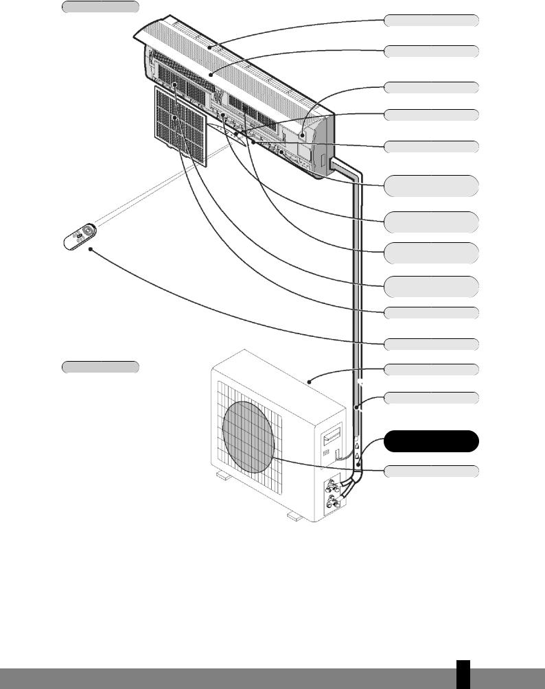
INDOOR UNIT
OUTDOOR UNIT
The diagrams in these instructions are based on a standard model.
The air conditioner you have purchased may be a different model.
Air inlet
Front panel
Emergency button
Display
Air outlet
Vertically adjustable vane
Horizontally adjustable vane
Active carbon filter (optional)
Healthy air filter (optional)
Air filter
Remote control
Air inlet
Drainage hose
Note: Condensation is drained during COOLING or DRYING
Pipes and power cable
Air outlet
4
5

C BEFORE USING
Check and adjust the following before using the air conditioner.
Adjusting the remote control
The manufacturer has NOT preset the remote control heating or cooling options.
The arrow for ‘Heat’ or ‘Cool’ on the remote control display will flash after the batteries in the remote control have been replaced.
Depending on the type of air conditioner that you have purchased, the remote control can be adjusted as follows:
Press any button while the ‘Heat’ arrow is flashing. This sets the heat pump.
Press any button while the ‘Cool’ arrow is flashing. The setting has been entered for cooling only.
If you do not press any button within 10 seconds, the remote control is automatically preset to the heat pump. Type S95, S125, S185 and S245 are fitted with a heat pump.
The Heat function can NOT be adjusted with the remote control when the remote control has been preset to Cool Only.
Safety regulations
•Use the correct power supply (see type plate) in order to prevent serious faults, hazards or fire.
•Ensure that the circuit breaker or plug does not become dirty. Connect the plug/circuit breaker to the power cable correctly. Insufficient contact may cause an electric shock or fire.
•Do not switch the unit off with the circuit breaker or by pulling the plug out of the socket. This may produce sparks that could start a fire.
•Do not tie any knots in the power cable or pull the power cable. This may damage or break the cable, causing an electric shock or fire.
•Never insert sticks or any similar object into the unit. The ventilator rotates at high speed and may cause injury.
•It is detrimental to your health to remain in the cold airstream for an extended period of time. We recommend that you allow the airstream to flow freely into the room, without obstruction.
•If a fault occurs, switch the machine off with the remote control before pulling the plug out of the socket.
•Do not carry out any repairs. Incorrect repairs may cause electric shocks, etc.
•Do not place gas burners or ovens in the airstream.
•Do not operate the buttons with wet hands.
•Do not place any objects on the outdoor unit.
•The user is responsible for the earth connection. This must be fitted by a recognised installer in accordance with local regulations and ordinances.
4
6
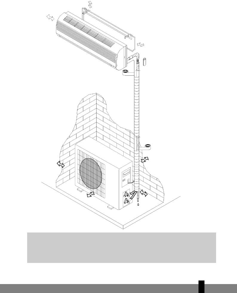
D INSTALLATION INSTRUCTIONS
Installation diagram
Distance to the wall must be a minimum of 50 mm.
Distance between the air inlet and the wall must be a minimum of 250 mm.
Distance between the air outlet and the wall must be a minimum of 500 mm.
Distance to the ceiling must be a minimum of 50 mm.
Distance to the wall must be a minimum of 50 mm.
Distance between the air inlet and the wall must be a minimum of 250 mm.
min. 250 mm.
Γ- The diagram above is a simplified illustration of the unit and may differ from the unit that you have purchased.
-The installation must be carried out by a recognised installer and connected in accordance with national regulations.
4
7

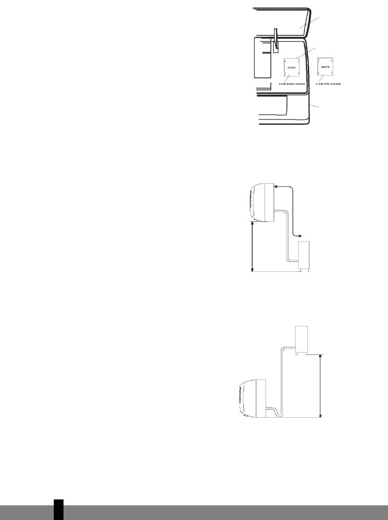
Connecting the power cable
Wiring between the indoor and outdoor unit:
1.Remove the plastic cover from the indoor unit.
2.Use the circuit diagram (attached to the indoor unit) as a reference for the connections.
3.Replace the cover, “B” on the outside.
Select the correct location
No obstacles in the vicinity of the air outlet. The air stream must be allowed to reach the entire room unhindered.
It must be possible to install the pipes and drill the hole in the wall at an accessible location.
Ensure that there is sufficient distance between the unit, ceiling and wall (refer to Chapter D).
It must be possible to remove the air filter easily.
The unit and remote control must be placed at least 1 metre from televisions, radios, etc.
Strip lights may cause faults. Ensure that there is sufficient distance.
Do not place any object in the vicinity of the air inlet. The air intake may not be blocked.
The wall must be strong enough to bear the weight of the unit. The wall construction may not cause any increase in noise and vibrations.
Location for the installation of the outdoor unit
In an accessible, well ventilated location. Do not mount at potentially hazardous locations, e.g. where there is a danger of a gas leak.
Maintain the required distance from the wall.
Do not expose the outdoor unit to greasy dirt or salty sea air. Do not mount in the vicinity of gas pipes.
Do not mount on the street side due to the risk of water splashing onto the unit.
Mount on a fixed foundation in order to prevent excessive noise.
The air outlet must not be obstructed.
Front panel
Connecting clamp (inside)
Housing
Installation diagram
Indoor unit
Not higher than 5 m
of a .S245) Outdoor unit
10 Max.m ofmax.(S125, lengthor(S95) m15S185,
Outdoor unit
Not higher than 5 m
Max. length of 10 m (S95) or a max. of 15 m (S125, S185, S245).
Indoor unit
4
8
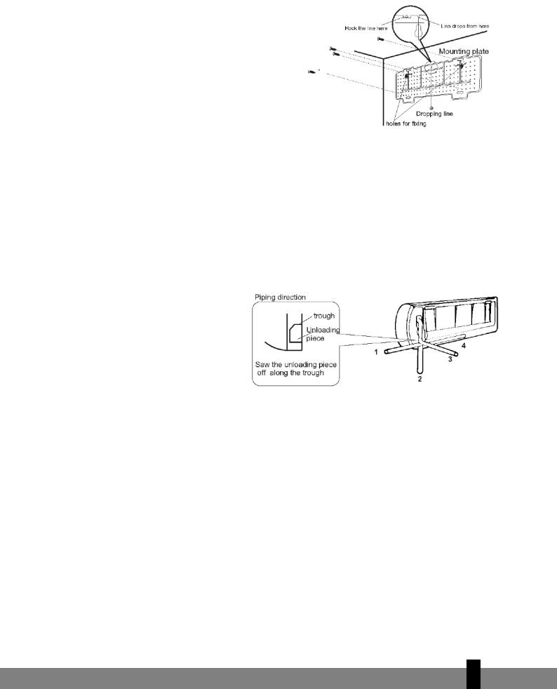
INSTALLATION OF THE INDOOR UNIT
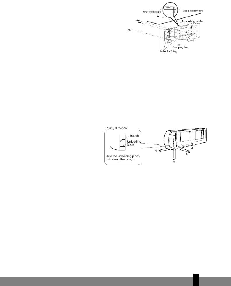
1.Installing the mounting plate
-Fit the mounting plate at the location where the indoor unit will be hung. Take account of the direction of the pipes.
-Place the mounting plate horizontally with the aid of a level indicator or plumb line.
-Drill holes with a depth of 32 mm in order to mount the plate.
-Insert the plastic plugs into the holes and screw the plate into position with selftapping screws.
-Check that the mounting plate is firmly in position and drill the hole for the pipes.
Note: the shape of the mounting plate may differ per model. However, the installation method is the same.
2.Drilling a hole for wires/pipes
-Determine the position of the lead-through hole for the wires/pipes on the basis of the drilling hole in the mounting plate.
-Drill the hole in the wall. The hole must slope a little to the outside.
-Place a pipe sleeve in the hole in order to protect the wall.
3.Indoor unit wire/pipe installation
-Insert he wires/pipes (gas and liquid pipes) through the hole from the outside, or from the inside if you have installed the indoor unit first.
-Create a recess that corresponds with the direction of the pipes.
Note: create recess 1, 2 or 4, depending on the position you have chosen for the hole in the indoor unit.
-Fit the drainage hose after connecting the wires/pipes. Now connect the power cables. Finish by insulating the pipes, cables and drainage hose.
Insulation of the pipe connections: Insulate the connection pieces with insulating material and then wrap
them in vinyl tape.
4
9

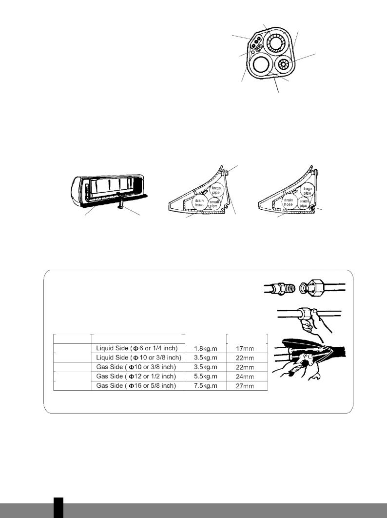
Pipe insulation:
a.Place the drainage hose under the pipe.
b.Use insulating material exceeding 6 mm in thickness.
-The drainage hose must slope downwards slightly in order to allow moisture to drain away easily.
Ensure that the drainage hose is not twisted and does not protrude. The end may not hang in the water.
If the drainage hose is extended with a hose, insulated.
|
|
|
|
Large pipe |
|
|
|
|
|
|
||||
|
|
|
|
|
|
|
Insulating pipe |
|||||||
|
|
|
|
|
|
|
|
|
|
|
|
|
|
|
|
|
Power cable |
|
|
|
|
|
|
|
|
||||
|
|
|
|
|
|
|
|
|
|
|
|
|||
|
|
|
|
|
|
|
|
|
|
|
|
|
|
|
|
|
|
|
|
|
|
|
|
|
|
|
|
|
|
|
|
|
|
|
|
|
|
|
|
|
|
Small |
||
Power cable 1 |
|
|
|
|
|
|
|
|
|
|||||
|
|
|
|
|
|
|
pipe |
|||||||
(heat pump) |
|
|
|
|
|
|
|
|
|
|||||
|
|
|
|
|
|
|
|
|
|
|||||
|
|
|
|
|
|
|
|
|
|
|
|
|
|
|
|
|
|
|
|
|
|
|
|
|
|
|
|
|
|
|
|
|
|
|
|
|
|
|
|
|
|
|
|
|
|
Wiring of defrosting |
|
|
|
Drainage hose |
|
||||||||
|
|
|
|
|
|
|
|
|
||||||
|
regulator (heat pump) |
|
|
|
|
|
|
|||||||
|
|
Tape |
|
|
|
|
|
|||||||
|
|
|
||||||||||||
|
|
|
|
|
|
|
|
|
|
|
|
|
|
|
the section running alongside the indoor unit must be
-If the wire/pipes are on the right hand side, the wires/pipes, power cable and drainage hose must be insulated and fastened to the back of the indoor unit with a pipe clamp.
A. Fasten the pipe clamp to the groove.
Push through here
|
|
|
|
|
|
|
|
|
|
Hook here |
Mounting plate |
|
Pipe clamp |
|
|
|
|
||||
|
|
|
|
Pipe clamp |
||||||
|
|
|
|
|
Mounting plate |
|||||
|
|
Mounting plate |
|
|
|
|
||||
|
|
|
|
|
|
|
|
|||
|
|
|
|
|
|
|
|
|
|
|
|
|
|
|
|
|
|
|
|
|
|
|
|
|
|
|
|
|
|
|
|
|
B.Press the clamp to attach it to the mounting plate.
Connecting the pipes
a.Connect the indoor unit pipes with two nut spanners. Select the correct tightening moment in order to prevent the pipes, connecting pieces and nuts from being deformed or damaged.
b.First tighten by hand, and then with nut spanners.
|
|
|
|
Tightening |
|
Nut |
Model |
|
Pipe dimensions |
||||
|
|
moment |
|
size |
||
|
|
|
|
|
||
|
|
|
|
|
|
|
S95/S125/S185
S245
S95
S125/S185
S245
4
10
4.Connecting the cable
-Indoor unit
Connect the power cable to the indoor unit by connecting the cables to the units to the clamps on the terminal board in the correct sequence. The colours of the wires and the reference on the clamps must correspond.
Note: In some models, the cover must be removed in order to connect the wiring.
-Outdoor unit
1.Remove the access cover of the unit by loosening the screw. Connect the wires to the clamps on the terminal board in the following manner:
2.Connect the power cable to the terminal board.
3.Replace the cover and tighten the screw.
4.Place an approved circuit breaker between the power source and the unit for model S245. Install a suitable main switch.
|
Front panel |
|
Terminal board |
|
|
|||
|
|
|
|
(inside) |
|
|
||
|
|
|
|
|
|
|||
|
|
|
|
|
|
|
|
|
|
|
|
|
|
|
|
|
|
|
|
|
|
|
|
Base plate |
||
|
|
|
|
|
|
|
||
Indoor unit |
|
|
|
|
|
|
||
|
|
|
|
|
Housing |
|
||
|
|
|
|
|
|
|
|
|
|
|
|
|
|
|
|
|
|
Access cover for terminal board (inside)
Outdoor unit
The illustrations are based on standard models.
The air conditioner you have purchased may be a different model.
Warning:
1.Always connect the air conditioner to a separate power circuit. Refer to the diagram on the inside of the access cover for the connection of the wires.
2.Check that the cable thickness conforms to regulations (see table below).
3.Check that all wiring is securely connected.
4.Install an earth leak switch.
Note: All cables used must be approved in accordance with local regulations.
Cable specifications
|
|
|
Power cable |
|
|
|
Power cable connection |
|
|
|
Power cable connection 1 (heat pump) |
||||||
|
|
|
|
|
|
|
|
|
|
|
|
|
|
|
|
|
|
|
|
|
|
|
|
|
|
|
|
|
|
|
|
|
|
|
|
|
|
|
Type |
Cross-section |
|
Type |
Cross-section |
Type |
Cross-section |
||||||||
|
|
|
|
|
|
|
|
|
|
|
|
|
|
|
|
|
|
|
|
|
|
|
|
|
|
|
|
|
|
|
|
|
|
|
|
|
|
|
|
|
|
|
|
|
|
|
|
|
|
|
|
|
|
|
|
|
|
|
|
|
|
|
|
|
|
|
|
|
|
|
|
|
|
|
|
|
|
|
|
|
|
|
|
|
|
|
|
|
|
S95
S125
S185
S245
4
11
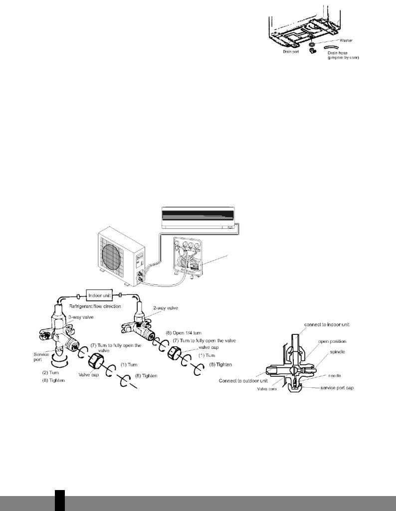
OUTDOOR UNIT INSTALLATION
1.Fit the drainage outlet and drainage hose (only for models with a heat pump).
Condensation will drip off the outdoor unit when the indoor unit is operating in Heating mode. Fit a drainage outlet and a drainage hose in order to drain the water effectively. Fit the drainage outlet and rubber washer to the base plate of the outdoor unit (see fig.).
2.Installing and fitting the outdoor unit Bolt the unit to a level and solid base.
Ensure that the unit is mounted securely in order to prevent problems caused by strong wind and vibrations.
3.Connecting the outdoor unit pipes
Remove the covers of the two-way and three-way valve.
Close the pipes separately with the appropriate tightening moment.
4.Outdoor unit cable connection (see previous page)
Purging the pipe system
Air and moisture that remain in the pipe system after installation can damage the compressor. After the indoor and outdoor units have been connected, air and moisture must be removed with the aid of a vacuum pump (see below).
Vacuum pump
Three-way valve diagram
4
12

1.Unscrew the two-way and three-way valve and remove the covers.
2.Unscrew the supply pipe and remove the cover.
3.Connect the flexible hose of the vacuum pump to the supply pipe.
4.Allow the vacuum pump to operate for 10-15 minutes until a pressure of 10 mmHg absolute is achieved.
5.Close the low-pressure button on the vacuum pump while the pump is still operating. Now switch the pump off.
6.Open the two-way valve (1/4 turn), and close it again after 10 seconds. Check all connections with liquid soap or an electronic leak detector.
7.Turn the two-way and three-way valves to their operating positions. Disconnect the hose from the vacuum pump.
8.Replace and tighten all covers.
Note
-Read these instructions for use before commencing installation.
-Make sure that no air remains in the cooling system and that no refrigerant is leaking.
-Testing: switch the air conditioner on after installation and take notes on the operation.
-Fuse of the indoor unit controller for types S95 and S125: 50T, permitted value 3.15 A,T, 250V. For types S185 and S245: 3.15A, T, 250V.
-The fuse for the unit as a whole must be suitable for maximum power.
-The plug must be easily accessible in order to be able to switch the unit off in case of emergency. If there is no easy access, a bipolar main switch must be installed at an easily accessible location.
4
13
E INSTRUCTIONS FOR USE
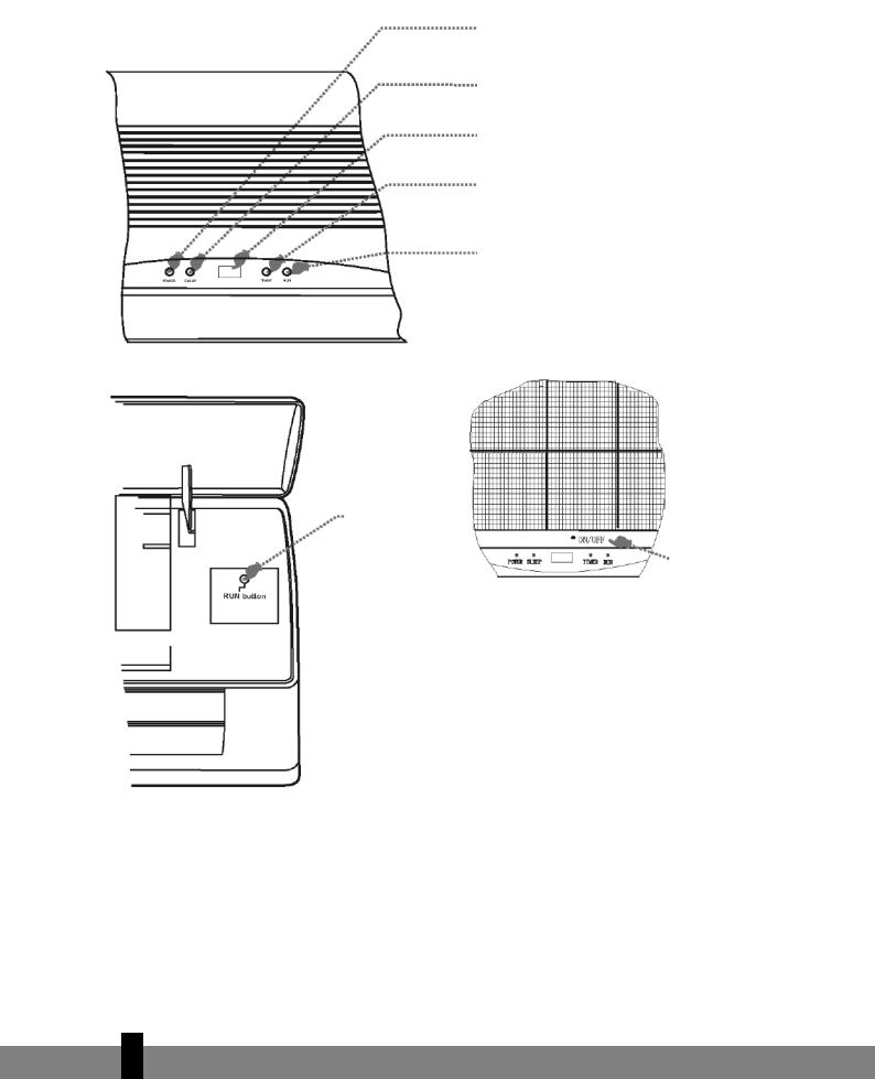
Operation and display
EMERGENCY BUTTON
To operate the unit if the remote control is not operational.
POWER INDICATOR
Lights up when power supply is connected.
SLEEP MODE INDICATOR Lights up when this function is activated.
RECEIVER
Receives the signal from the remote control.
TIME INDICATOR
Lights up during preset time.
OPERATING INDICATOR
Lit when the unit is in operation.
EMERGENCY BUTTON To operate the unit if the remote control is not operational.
Adjustment of automatic restart
The machine has been programmed by the manufacturer to restart automatically.
Following a power cut, the machine will resume operation in the last selected function.
The shapes and positions of the switches and indicators may differ for each model. However, the functions are identical.
4
14
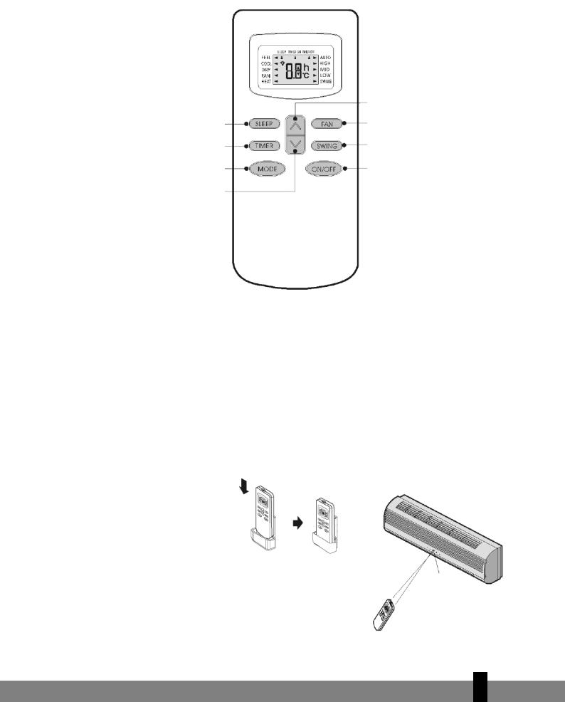
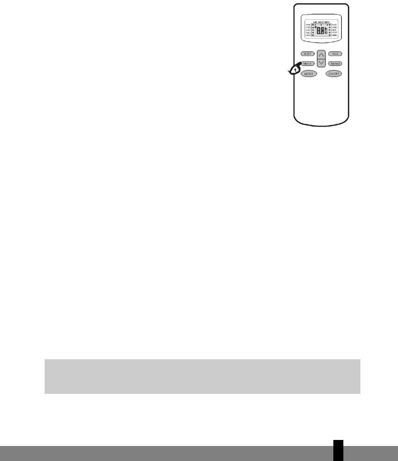
Remote control
The remote control transmits signals to the system.
SLEEP button
To activate or deactivate the sleep mode.
TIMER button
To select the TIMER function.
MODE button
To select the operating mode: Feel, Cooling,
Dry, Fan and Heating.
DOWN button (TOO WARM button) To lower the preset room temperature and reduce time periods.
UP button (TOO COLD button)
To raise your preset room temperature and extend time periods.
FAN SPEED operation button
For the selection of the ventilator speed in the indoor unit: automatic, high, medium and low.
Horizontal plate button
To adjust the direction of the airstream.
ON/OFF button
For activation and deactivation.
Note: Each mode and the relevant functions will be specified hereafter.
Placing the batteries
Remove the battery cover in the direction of the arrow.
Place the new batteries as indicated (ensure that the positive (+) and negative poles (-) are in the correct positions. Slide the battery cover back into place.
Note: Use 2 LR03 AAA (1.5 Volt) batteries. Do not use rechargeable batteries. Replace the batteries with new batteries of the same type (see above) when the display starts to fade.
Storage of the remote control and tips for use
The remote control can be placed in a wall-mounted holder.
Note: The remote control holder is optional.
Using the remote control
Point the remote control at the receiver on the indoor unit of the
Receiver
air conditioner. The air conditioner can be operated in this manner up to a distance of 7 metres.
4
15
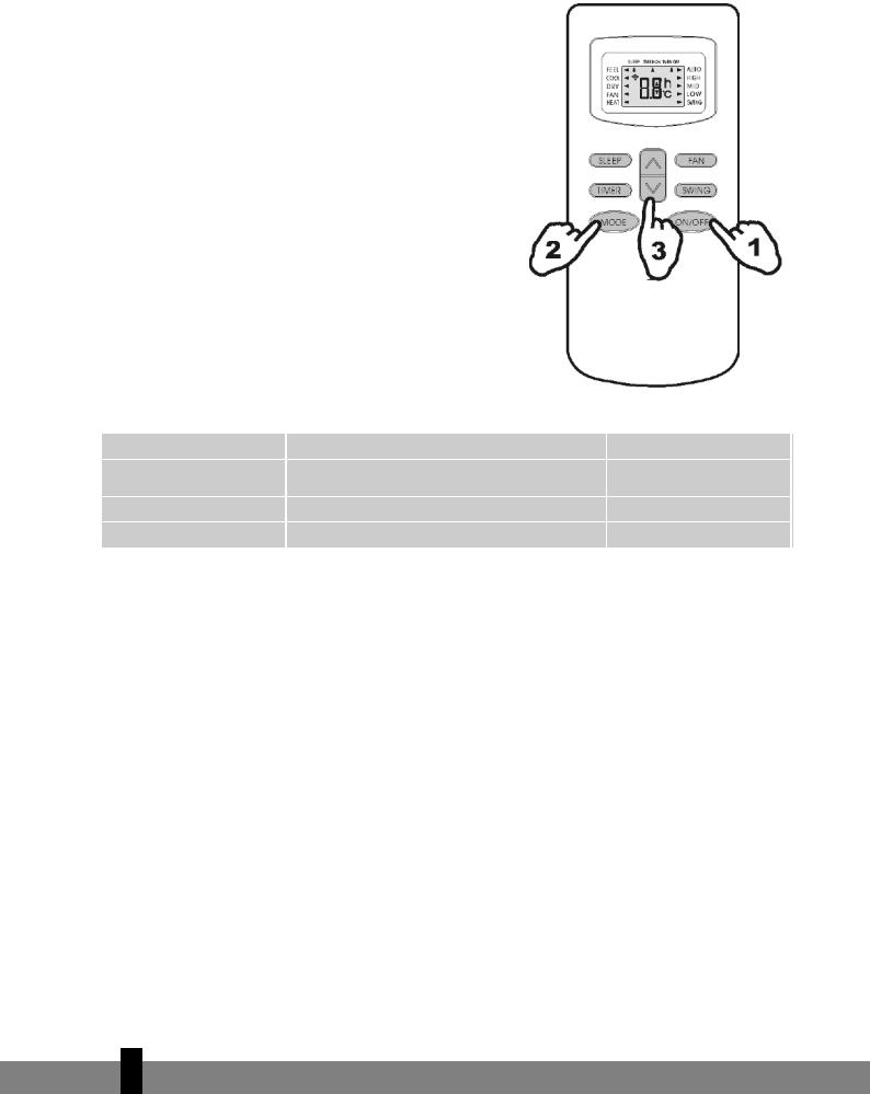
OPERATING INSTRUCTIONS
FEEL mode operating procedure
The operating mode is selected automatically (HEATING, DRY, FAN, COOLING), depending on the room temperature at the time the selection takes place.
With the remote control pointed at the air conditioner.
1.Activation
Press the ON/OFF/RUN button. The RUN indicator on the indoor unit will light up when the machine receives a signal.
When the unit is not in the FEEL mode.
2.Selecting the FEEL mode
Press the MODE selector button. Adjust the MODE to the FEEL setting.
The operating mode and temperature are determined by the indoor temperature.
Indoor temperature |
Operating mode |
|
Less than 20 °C |
Heating for ‘heat pump’ type |
|
Ventilator for ‘cooling only’ type |
||
|
||
20 – 26 °C |
DRY |
|
More than 26 °C |
COOLING |
Desired temperature
23 °C
18 °C
23 °C
3.Temperature adjustment
Press the g button or the h button.
When the g button is pressed, the value of the preset temperature increases by 1°C. The indicator will not change after the temperature has been increased by 2°C. When the h button is pressed, the value of the preset temperature is lowered by 1°C. The indicator will not change after the temperature has been lowered by 2°C.
Note:
It may occur that no air is expelled from the unit while it is in operation.
The unit will not always start operating immediately after the mode has been changed.
TIMER mode
If you program the timer with the TIMER button upon leaving, it will be pleasantly warm when you return home. You can deactivate the timer at night if you wish.
4
16
ADJUSTING THE TIMER
To activate the air conditioner at the desired time, follow the procedure specified below (the remote control and air conditioner are switched off):
1.Press the Timer button.
2.Select the desired mode by pressing the Mode button.
3.Select the desired temperature by pressing the gh button (only possible when the ‘cool’ or ‘heat’ mode is selected).
4.Select the ventilator speed (low, medium or high) or automatic mode (only possible when the Feel, Cool or Heat mode is selected) by pressing the Fan button.
The ventilator always operates in the Auto mode when the Dry mode is selected.
5.Select Swing or no Swing by pressing the Swing button.
6.Press the Timer button (‘h’ flashes).
7.Use the gh button to select the time at which the air conditioner must activate (between 0 and 10 hours can be set at every half hour – between 10 and 24 hours can be set at every hour).
8.Press the Timer button (‘h’ stops flashing) and the preset time appears in the display.
9.Press the Timer button again to delete the selected data from the memory.
Note: If no buttons are pressed during the programming of the timer function, the remote control will switch off automatically after 10 seconds.
To switch the air conditioner off at the desired time, follow the procedure specified below (the remote control and air conditioner are switched off):
1.Press the Timer button.
2.Use the gh button to select the time at which the air conditioner must deactivate (between 0 and 10 hours can be set at every half hour – between 10 and 24 hours can be set at every hour).
3.Press the Timer button (‘h’ stops flashing), and the preset time will appear in the display.
4.Press the Timer button again to delete the selected data from the memory.
Note: If no buttons are pressed during the programming of the timer function, the remote control will switch off automatically after 10 seconds.
Note: if ‘h’ is flashing and you press the ON/OFF/RUN button once, the preset temperature will appear in the display. You can now adjust the temperature with the gh button. Press the Timer button again to display the time, which can now also be adjusted*. If the Timer button is pressed again, the data is stored and the remaining time (that the air conditioner will be in operation) will appear in the display.
*ΓPressing the ON/OFF/RUN button instead of the Timer button deactivates the remote control.
Press the Timer function to check the settings in the display.
4
17
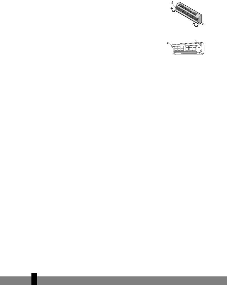
F MAINTENANCE
Cleaning the front panel
1Switch the machine off and remove the plug from the socket.
2Hold the front panel at position “a” and pull it towards you.
3Clean with a soft dry cloth.
Use lukewarm water (max. 30˚ C) to remove stubborn dirt.
4Never use volatile substances, such as benzene, or abrasives to remove dirt.
5Never spray water on the indoor unit. Dangerous! Electric shock!
6Replace the front panel and close it by pushing position “b” down.
Cleaning the air filter
The air filter must be cleaned regularly.
Follow this procedure:
1.Switch the machine off completely.
-Open the front panel.
-Carefully pull the filter handle towards you.
-Grip the handle and slide the filter out.
2.Clean and replace the air filter.
To remove stubborn dirt, clean the filter in lukewarm water with detergent. After cleaning, allow the filter to dry completely out of direct sunlight.
3.Close the front panel.
If the air conditioner is operating in an extremely dusty environment, it must be cleaned every two weeks.
G SAFETY
Operating status
The safety components can detect faults and deactivate the unit in the following cases:
HEATING
The outside temperature is above 24°C
The outside temperature is under -7°C
The room temperature is above 27°C
COOLING
The outside temperature is above 43°C
The room temperature is under 21°C
DRY
The room temperature is under 18°C
4
18

ΓWarning
If the air conditioner is operating in the COOLING or DRY mode while relative humidity is over 80%, moisture may drip out of the air outlet of the indoor unit (due to a window or door being open, for instance).
Noise
-Install the air conditioner on a solid base in order to prevent excessive noise.
-Install the outdoor unit in such a way that the expelled air does not cause a nuisance for neighbours.
-Do not place obstacles in the path of the air expelled from the outdoor unit, this increases noise.
Safety features
1The safety feature deactivates the unit in the following cases:
-When the function is stopped or changed while the unit is operating. Wait 3 minutes before switching the air conditioner on again.
-After the plug has been inserted in the socket and the unit has been immediately switched on. The
unit will activate after approximately 20 seconds.
2.Press the ON/OFF button to restart after the unit has deactivated due to the operation of the safety feature. The Timer must then be reset.
Checks
The following must be checked after the air conditioner has been in use for an extended period of time:
-Overheating of the power cable and the plug. Can you smell burning?
-Is there more noise or vibration than normal?
-Does the indoor unit leak water?
-Is the metal housing live?
Switch the air conditioner off in all the above cases! We recommend periodic inspection by a registered installer (at least once every five years).
Feature of the HEATING mode
For heating
When the HEATING function is activated, the airstream will only start to flow from the indoor unit after 2 – 5 minutes.
After Heating
When the Heating function is deactivated, the ventilator of the indoor unit will continue operating for another 2 – 5 minutes.
Defrosting
During HEATING, the machine will defrost automatically in order to ensure optimum operating efficiency. This procedure usually takes 2-10 minutes. The ventilator function stops during defrosting. The HEATING function restarts automatically after defrosting.
4
19

H PROBLEM SOLVING
The following problems do not always indicate a fault. Please check them before contacting the service
department:
Problem |
Cause / Solution |
|
|
The plug is not inserted firmly in the socket. |
|
The unit does not operate. |
The batteries in the remote control are empty. |
|
|
The safety feature has been activated or the fuse has burnt out. |
|
|
Are the air inlets or outlets blocked? |
|
No cooled or heated air. |
Is the temperature set correctly? |
|
|
Is the air filter dirty? |
|
|
Faults (due to static electricity discharges or disruptions in the |
|
No effective operation. |
power supply) will prevent the machine from operating correctly. |
|
If this is the case, pull the plug out of the socket, and then re- |
||
|
||
|
insert it after 2-3 seconds. |
|
Does not start immediately. |
Changing the mode during operation: 3 minute delay. |
|
Unusual odour. |
Odour may be caused by another source – furniture, cigarettes, |
|
etc. The unit expels air that it has sucked in. |
||
|
||
|
Caused by the refrigerant in the air conditioner: this does not |
|
The sound of running water. |
indicate a fault. |
|
|
||
|
The sound of defrosting in the heating mode. |
|
A creaking sound. |
The sound may be caused by the expansion/shrinkage of the front |
|
panel as a consequence of temperature fluctuations. |
||
|
||
|
Condensation/mist is created when the air temperature in the |
|
Mist/moisture is expelled from the air outlet. |
room drops significantly due to the fact that cold air is expelled in |
|
|
the COOLING or DRY mode. |
|
The red compressor indicator flashes |
The unit will switch from the heating mode to the defrosting |
|
constantly and the ventilator in the indoor |
mode. The indicator light will go out within 10 minutes and the |
|
unit ceases to operate. |
unit will return to the heating mode. |
|
|
|
4
20
I GUARANTEE CONDITIONS
There is a 24-month guarantee on the air conditioner from the purchase date. Within this period, all material and manufacturing defects will be repaired free of charge. The following rules will apply:
•We expressly reject all further claims to damage compensation, including claims relating to secondary damage.
•Repairing or replacing components within the guarantee period will not extend the guarantee.
•The guarantee is invalidated if any modifications have been made to the machine, non original parts have been fitted or repairs have been carried out by third parties.
•Components subject to normal wear, such as the filter, are not covered by the guarantee.
•The guarantee is valid exclusively when you present the original, dated and unaltered purchase invoice.
•The guarantee does not cover damage caused by actions that deviate from the instructions for use or neglect.
•Shipment costs and the risks associated with shipping the air conditioner or parts thereof will always be borne by the buyer.
To prevent unnecessary expense, we recommend that you first always consult the instructions for use carefully. If this does not provide a solution, ask your dealer to repair the air conditioner.
4
21

Egregio Signore, Gentile Signora,
Ci congratuliamo con per l’acquisto del condizionatore d’aria. Lei ha acquistato un
prodotto di qualità, che Le offrirà molti anni di comfort, a condizione che venga usato in
modo responsabile. Per una durata ottimale del condizionatore d’aria La invitiamo a
leggere le istruzioni d’uso. A nome del fabbricante Le offriamo 24 mesi di garanzia per
tutti i danni imputabili alla produzione o al materiale.
Le auguriamo molta freschezza e comfort.
Cordiali saluti,
PVG International b.v.
Reparto Assistenza Clienti

 1. LEGGERE DAPPRIMA LE ISTRUZIONI D’USO


 2. IN CASO DI DUBBIO, RIVOLGERSI AL RIVENDITORE


>
22

CONTENUTO |
|
|
|
A |
Specifiche |
pagina |
24 |
B |
Componenti |
pagina |
25 |
C |
Operazioni preliminari |
pagina |
26 |
D |
Istruzioni per l’installazione |
pagina |
27 |
E |
Istruzioni d’uso |
pagina |
34 |
F |
Manutenzione |
pagina |
38 |
G |
Sicurezza |
pagina |
38 |
H |
Risoluzione dei problemi |
pagina |
40 |
I |
Condizioni della garanzia |
pagina |
41 |
>
23
A SPECIFICHE
I valori riportati sono indicativi, dati soggetti a modifiche
Modello |
|
S95 |
S125 |
S185 |
S245 |
Ca. di raffreddamento* |
kW |
2,7 |
3,5 |
5,3 |
7,0 |
EE Class |
|
D |
D |
D |
D |
EER * |
|
2,8 |
2,8 |
2,8 |
2,9 |
Capacità di riscaldamento |
kW |
2,8 |
3,8 |
5,7 |
7,6 |
COP Class |
|
D |
D |
D |
D |
COP * |
|
3,2 |
3,2 |
3,4 |
3,5 |
Deumidificazione (max) ** |
L/24 h |
19 |
24 |
36 |
48 |
Assorbimento energia in raffreddamento |
kW |
0,88 |
1,17 |
1,9 |
2,6 |
Assorbimento energia in riscaldamento |
kW |
0,88 |
1,17 |
1,9 |
2,6 |
Alimentazione |
Volt/Hz/Pf |
220-240/50/1 |
220-240/50/1 |
220-240/50/1 |
220-240/50/1 |
Corrente (nom) |
A |
3,6 |
5,1 |
8,7 |
12,8 |
Flusso aria (max) |
m3/h |
480 |
550 |
730 |
1000 |
Ideale per ambienti fino a |
m3 |
90 |
110 |
150 |
200 |
Dimensioni unità interna (PxLxH) |
mm |
718x180x240 |
770x180x240 |
1033x202x313 |
1033x202x313 |
Dimensioni unità esterna (PxLxH) |
mm |
669x296x506 |
769x328x552 |
829x328x552 |
929x372x652 |
Peso unità interna |
kg |
7 |
7 |
14 |
14 |
Peso unità esterna |
kg |
24 |
32 |
42 |
56 |
Refrigerante |
gr |
R407C/540 |
R407C/900 |
R407C/1680 |
R407C/2300 |
Livello di rumore unità interna (max) |
dB(A) |
36 |
38 |
43 |
47 |
Livello di rumore unità esterna (max) |
dB(A) |
50 |
50 |
60 |
54 |
Temperatura di esercizio |
ºC |
10-40 |
10-40 |
10-40 |
10-40 |
Protezione unità interna |
IP |
IP X0 |
IP X0 |
IP X0 |
IP X0 |
Protezione unità esterna |
IP |
IP X4 |
IP X4 |
IP X4 |
IP X4 |
|
|
|
|
|
|
*Conforme a EN 14511
**Tasso di humidità relativa pari al 80% ad una temperatura di 32°C
Gli apparecchi elettrici difettosi e le batterie usate non devono essere smaltiti come rifiuti domestici. Se possibile utilizzarli per il riciclaggio. Eventualmente informarsi presso il proprio comune o il rivenditore locale sulle possibilità di riciclaggio o di smaltimento ecologico.
>
24

B IDENTIFICAZIONE DEI COMPONENTI
UNITÀ INTERNA
UNITÀ ESTERNA
Le figure riportate nel presente manuale si riferiscono a un modello standard.
Il vostro condizionatore può essere un modello diverso.
Presa d’aria
Quadro frontale
Pulsante di emergenza
Display
Uscita dell’aria
Regolazione verticale delle lame
Regolazione orizzontale delle lame
Filtro anti-par- ticelle di carbon attivo (optional)
Filtro di sicurezza per la tutela della
salute (optional)
Filtro dell’aria
Telecomando
Presa d’aria
Tubo flessibile di scarico*
Tubi e cavo di alimentazione
Uscita dell’aria
* NB: la funzione di scarico dell’aria di condensa è attiva in modalità CONDIZIONAMENTO o DEUMIDIFICAZIONE
>
25

C PREPARATIVI PRIMA DELL’USO
Prima di utilizzare il condizionatore d’aria, verificare e impostare i seguenti parametri.
Impostazione del telecomando
Il telecomando NON è impostato direttamente in fabbrica per utilizzare l’apparecchio come generatore di aria fredda ad uso condizionamento (condizionatore) o di aria calda ad uso riscaldamento (pompa di calore). Ad ogni sostituzione delle batterie del telecomando, sul display frontale lampeggerà l’apposita freccia luminosa “Heat” (“caldo”) o “Cool” (“freddo”).
È possibile impostare il telecomando in funzione del tipo di apparecchio acquistato nel modo seguente: premere un pulsante qualsiasi quando la freccia luminosa posta sul display frontale lampeggia in corrispondenza della dicitura “Heat” (“caldo”), viene selezionata la funzione “pompa di calore”.
premere un pulsante qualsiasi quando la freccia luminosa posta sul display frontale lampeggia in corrispondenza della dicitura“Cool” (“freddo”), viene selezionata la funzione “condizionamento”.
Se non viene premuto alcun pulsante entro 10 secondi, il telecomando viene impostato automaticamente per la funzione “pompa di calore”. Gli apparecchi S95, S125, S185 e S245 sono dotati di una pompa di calore.
Impostando il telecomando per utilizzare l’apparecchio solo a fini di condizionamento, NON è possibile impostare la funzione di riscaldamento con il telecomando.
Precauzioni di sicurezza
•Utilizzare il corretto valore di tensione in funzione di quanto indicato sull’apposita targhetta per evitare gravi danni all’apparecchio o rischi di incendio.
•Tenere costantemente pulito l’interruttore o la spina di alimentazione. Collegare l’interruttore/spina in modo saldo e preciso al cavo di alimentazione. Un contatto insufficiente potrebbe essere causa di elettroshock o incendio.
•Non utilizzare l’interruttore o togliere la spina per spegnere l’apparecchio quando è in funzione. Esiste il rischio di propagazione di scintille che potrebbero causare un incendio.
•Non torcere, tirare o schiacciare il cavo di alimentazione per evitare rischi di elettroshock o incendio.
•Non inserire oggetti estranei quali bastoni o simili nell’apparecchio. A causa dell’elevata velocità di rotazione della ventola possono verificarsi incidenti.
•Evitare un’esposizione diretta prolungata al flusso di aria fredda in provenienza dall’apparecchio. Si consiglia di optare per un flusso diffuso.
•In caso di malfunzionamento, spegnere l’apparecchio con il telecomando prima di togliere la spina dalla presa di alimentazione
•Non procedere direttamente alla riparazione dell’apparecchio. Riparazioni non eseguite da personale specializzato possono provocare elettroshock ecc….
•Evitare di dirigere il flusso d’aria verso cucine a gas e stufe.
•Non toccare i pulsanti con le mani bagnate.
•Non inserire alcun oggetto nell’unità esterna.
•La messa a terra conforme alle leggi o norme locali da parte di un tecnico autorizzato rientra nelle responsabilità dell’utente.
>
26

D ISTRUZIONI PER L’INSTALLAZIONE
Schema di installazione
La distanza dal muro deve essere superiore a 50 mm.
La distanza tra il bocchettone di uscita dell’aria e il muro deve essere superiore a 250 mm.
La distanza dal soffitto deve essere superiore a 50 mm.
La distanza dal muro deve essere superiore a 50 mm.
La distanza tra il bocchettone di uscita dell’aria e il muro deve essere superiore a 250 mm.
La distanza tra il bocchettone |
minimo 250 mm. |
|
di uscita dell’aria e il muro deve |
||
|
||
essere superiore a 500 mm. |
|
Γ- La figura sovrastante è una presentazione semplificata dell’apparecchio, che potrebbe differire rispetto al prodotto da voi acquistato.
-L’installazione deve essere eseguita esclusivamente da personale autorizzato nel rispetto delle normative nazionali.
>
27
Collegamento del cavo di alimentazione
Connessione tra l’unità interna e l’unità esterna
1.Rimuovere il rivestimento in plastica dell’unità interna.
2.Per il collegamento far riferimento al diagramma dei cablaggi (allegato all’unità interna).
3.Ricollocare il rivestimento in plastica. Verificare che il lato “B” sia all’esterno.
Scegliere la migliore collocazione per l’apparecchio.
Non collocare alcun ostacolo nei pressi del bocchettone di uscita dell’aria in modo tale che l’aria sia libera di circolare in ogni punto della stanza.
I tubi e il foro da praticare nel muro devono essere in posizioni accessibili.
Predisporre uno spazio adeguato dall’apparecchio al soffitto e al muro (cfr. capitolo D).
I filtri dell’aria devono essere facilmente estraibili.
Tenere l’apparecchio e il telecomando a una distanza minima di 1 m da televisore, radio, ecc.
Le lampade fluorescenti possono causare interferenze. Tenerle ad adeguata distanza.
Non mettere nulla vicino al bocchettone di uscita dell’aria, in modo tale da garantire la massima circolazione dell’aria. Il muro deve essere sufficientemente solido per sostenere il peso del condizionatore e non contribuire ad aumentare il rumore e le vibrazioni prodotti durante il funzionamento.
Collocazione dell’unità esterna
Collocare l’unità esterna in un punto accessibile e ben ventilato; non collocarla, per esempio, in un punto che presenti pericolo di perdite di gas.
Mantenere la corretta distanza dal muro.
L’unità esterna non deve essere esposta ad aria di mare sporca, grassa o salata o collocata nei pressi di tubi di scarico.
Non installare lungo una strada per evitare spruzzi di acqua.
Predisporre una base fissa per evitare l’aumento della produzione di rumore.
Verificare che l’aria possa circolare liberamente.
Quadro frontale
Morsetto di collegamento (interno)
Cassa
Schema di installazione
Unità interna
Altezza max. pari a 5 m.
Lunghezza max. |
dei tubi: 10 metri |
(S95) o 15 metri (S125, S185, S245) |
Unità esterna |
|
Unità esterna
Altezza max. pari a 5 m.
Lunghezza max. dei tubi: 10 metri (S95) o 15 metri (S125, S185, S245)
Unità interna
>
28
Installazione dell’unità interna
1.Installazione del piano di supporto
-scegliere il punto dove collocare il piano di supporto dell’unità esterna tenendo conto della direzione dei tubi;
-disporre il piano di supporto orizzontalmente con l’ausilio di una riga orizzontale o di una bolla;
-praticare fori di 32 mm di profondità nel muro per fissare il piano di supporto;
-inserire i tasselli in plastica nei fori e fissare il piano di supporto con viti a filetto tagliente;
-verificare che il piano di supporto sia ben fissato. Praticare poi un foro per i tubi.
NB: la forma del piano di supporto varia da modello a modello, ma il metodo di installazione è identico.
2. |
Praticare un foro per i tubi |
- |
Determinare la posizione del foro per i tubi nel muro in base al foro nel piano di supporto; |
- |
praticare un foro nel muro. Il foro dovrebbe deviare leggermente verso l’esterno; |
- |
inserire un manicotto nel foro per proteggere il muro. |
3. |
Installazione tubi unità interna |
-Inserire i tubi (del liquido e del gas) e i cavi nel buco praticato nel muro partendo dall’esterno verso l’interno oppure dall’interno verso l’esterno qualora sia già stata installata l’unità interna;
-tagliare il segmento in plastica in funzione della direzione dei tubi.
NB: tagliare il segmento in plastica 1, 2 o 4, in funzione della posizione scelta per il foro nell’unità interna.
-dopo aver installato i tubi, installare il tubo flessibile di scarico. Dopodiché collegare i cavi di alimentazione. Infine isolare i tubi, i cavi e il tubo flessibile di scarico.
Isolamento termico giunti tubi. Avvolgere i giunti dei tubi con un materiale isolato termicamente e poi applicare del nastro in vinile.
>
29
Isolamento termico tubi
a. collocare il tubo flessibile di scarico sotto i  tubi;
tubi; 
b.utilizzare materiale di isolamento con
|
spessore maggiore di 6 mm; |
|
|
|
|
|
Tubo di piccole |
|
|
Cavo di alimen- |
|
|
|
||||
- |
il tubo flessibile di scarico deve puntare |
|
|
|
dimensioni |
|||
tazione 1 (per |
|
|
|
|||||
|
|
|
|
|
||||
|
verso il basso per agevolare lo scarico. |
pompa di calore) |
|
|
|
|
|
|
|
|
|
|
|
|
|
|
|
|
Verificare che il tubo flessibile di scarico |
|
|
|
|
|
|
|
|
|
|
|
|
Tubo flessibile |
|||
|
|
Cavo per regolazione dello |
|
|
||||
|
non sia piegato, avvolto su se stesso o |
|
|
di scarico |
|
|||
|
|
sbrinamento (per pompa |
|
|
||||
|
sporgente; non immergerne l’estremità in |
|
Nastro |
|
|
|
||
|
|
di calore) |
|
|
||||
|
|
|
||||||
|
|
|
|
|
|
|||
acqua.
Se il tubo flessibile di scarico è collegato a una prolunga, la parte che passa lungo l’unità interna deve essere isolata.
-Quando i tubi sono diretti verso destra, i tubi, il cavo di alimentazione e il tubo flessibile di scarico devono essere isolati e montati sul retro dell’unità interna con un apposito dispositivo di fissaggio.
Inserire qui
|
|
|
|
|
|
|
|
|
Fissare qui |
Piano di |
|
Dispositivo di fis- |
|
|
|
||||
|
|
|
Dispositivo di fis- |
||||||
|
|
|
|
Piano di |
|||||
|
|
Piano di |
|
|
|
||||
supporto |
|
saggio del tubo |
|
|
|
|
|||
|
|
supporto |
saggio del tubo |
|
supporto |
|
|
||
|
|
|
|
|
|
|
|||
|
|
|
|||||||
|
|
|
|||||||
|
|
|
|
|
|
|
|
|
|
|
|
|
|
|
|
|
|
|
|
A.Inserire il dispositivo di fissaggio del tubo nell’alloggiamento
B.Premere per agganciare il dispositivo di fissaggio del tubo al piano di supporto
Vollegamento dei tubi
a.Collegare i tubi dell’unità interna con due chiavi. Prestare particolare attenzione alla coppia di serraggio consentita, in modo tale da evitare che i tubi, i giunti e i dadi si deformino o danneggino.
b.Stringergli prima con le dita, poi utilizzare le chiavi.
Modello |
Dimensione del tubo |
Serraggio |
Ampiezza |
dei dadi
S95/S125/S185
S245
S95
S125/S185
S245
>
30
 Loading...