

Page 1
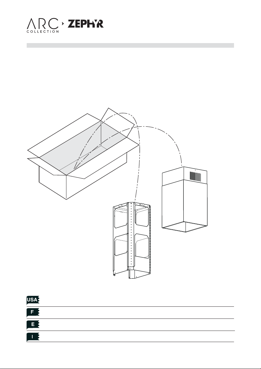
Duct Cover Extension Short, Long
Z1C-00LL
Z1C-01LL
For use with Layers Is. and Duo Is. range hood
customer service
1.888.880.8368
Mounting the duct cover Pag. 4
Fixation des cheminees Pag. 6
Fijación de las chimeneas Pag. 8
Fissaggio dei camini Pag. 10
Page 2
www.zephyronline.com
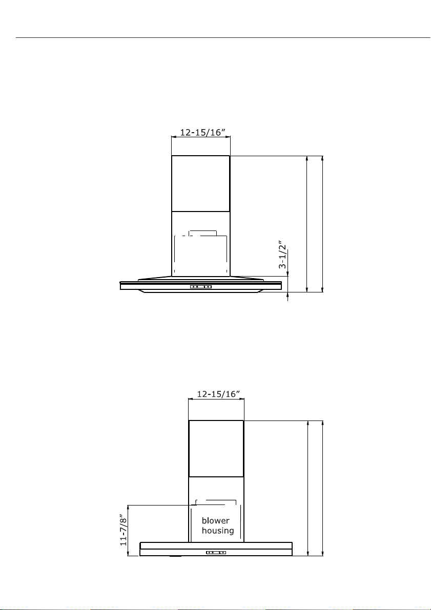
DUCT COVER EXTENSION SPECIFICATION
LAYERS IS.
Longer size: Min 53,5" - Max 79"
Short size: Min 37,5"- Max 49"
DUO IS.
- 2 -
Longer size: Min 53,5" - Max 79"
Short size: Min 37,5"- Max 49"
Page 3
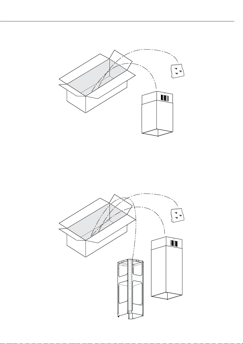
KIT Z1C-00LL Duct Cover Short
KIT Z1C-01LL Duct Cover Long
- 3 -
Page 4
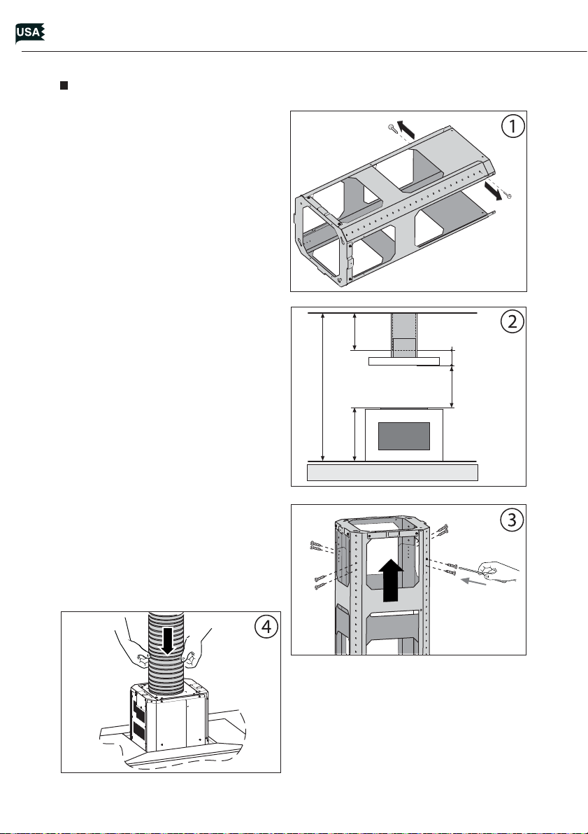
MOUNTING THE DUCT COVER
1. Remove the (2) screws to unlock
the top support frame from the
bottom support frame. Fig.1.
Adjust the height by referring to
the diagram in Fig. 2. Secure the
support frames together with (2)
screws per extension arm (Tot. 8).
Fig.3
2. Place correct size ducting for your
installation (not supplied) on top
of hood and secure to the blower
collar with aluminum duct tape.
The ducting should be long enough so it protrudes out the top of
the support frame and extends
into the attic to connect after the
hood is installed. Fig.4
3. Place assembled support frames
on top of hood and secure it to the
hood body using 8 screws. Fig.5
Installation - Mounting the Duct Cover
4. Place duct covers over assembled
support frame until they rest on
the hood body. Fig.6
www.zephyronline.com
X
4,3 - 1/16"
C
24"
B
X = C - (4,3-1/16" + 24" + B)
5. Position hole template on the ceiling
paying attention that the arrow is positioned on the same side as the range
hood controls. Fig.7
- 4 -
Page 5

- Make 4, holes in the ceiling and drive in
(3) screws without completely tightening them. Pay attention not to insert
the screw into the hole marked with
an X on the hole template Fig.7
6. Lift the hood assembly to the ceiling and align the top support frame with the (3) screws previously
installed in the ceiling.
- Rotate assembly slightly clockwise
to lock in place. Fig.8A. Drive in
the fourth screw and tighten the
remaining 3 screws to secure the
structure in place. Fig.8B
7. Extend the upper duct cover and secure it to the
top support frame by using (2) screws. Fig.9
8. Verify that ducting from hood is connected to
ducting in the attic that will exhaust air out of
the home.
- 5 -
Installation - Mounting the Duct Cover
Page 6

FIXATION DES CHEMINEES
1. Enlevez les (2) vis pour séparer la
partie supérieure de la partie inférieure. Fig. 1. Régler la hauteur
désirée en se référant aux cotes
indiquées dans la ( g. 2) et la bloquer au moyen des (2 ) vis fournies
avec l’appareil. (Tot. 8 )Fig.3
2. Positionnez le conduit (non fourni)
proportionné à l’installation sur
la partie supérieure de la hotte et
xez-le au collier du reni ard en
utilisant le ruban aluminium spécial. Le conduit doit être assez long
pour sortir de la partie supérieure
du cadre de support et pour s’étendre jusqu’à l’intérieur du grenier. Le
conduit sera relié une fois la hotte
installée. Fig. 4
3. Positionnez le cadre de support installé sur la partie supérieure de la
Installation – Fixation De Cheminees
hotte et xez-le au corps de la hotte à l’aide des 8 vis ( g. 5).
www.zephyronline.com
X
4,3 - 1/16"
C
24"
B
X = C - (4,3-1/16" + 24" + B)
4. Emboîtez les cheminées par la
structure jusqu’à ce qu’elles aillent
se poser sur la hotte. Fig. 6
5. Positionner le gabarit de forure au
plafond en faisant attention à ce que la
èche soit positionnée du même côté
que la commande de l’appareil. Fig.7
- 6 -
Page 7

- E ectuer les 4 trous au plafond et
visser (3) vis sans les serrer complètement et en prenant garde de
ne pas insérer la vis dans le trou
marqué par un X sur le gabarit de
forure. Fig. 7
6. Soulevez la hotte vers le haut et
procédez à l’alignement du cadre
de support supérieur avec les (3)
vis précédemment xées au plafond.
- Faire une petite rotation pour l’encastrement. Fig. 8A. Visser la quatrième vis X et serrer les 3 autres
qui restent pour permettre le blocage dé nitif de la partie supérieure de la structure. Fig. 8B
7. Prendre le conduit de fumées supérieur et le xer
à la structure à l’aide des (2) vis. Fig. 9
Installation – Fixation De Cheminees
8. Véri ez que le conduit sortant de la hotte est
bien relié au conduit du grenier pour l’évacuation extérieure.
- 7 -
Page 8

FIJACIÓN DE LAS CHIMENEAS
1. Quite los (2) tornillos para desbloquear la parte superior de la inferior. Fig. 1. Regule la altura deseada
re riéndose a las cuotas indicadas
en ( g.2) y jar conlos (2) tornillos
incluidos. (Tot. 8)Fig.3
2. Coloque el conducto (no suministrado) de dimensiones adecuadas
a la instalación, en la parte más alta
de la campana y fíjelo al collar del
purgador mediante una cinta de
aluminio. El conducto debe ser lo
su cientemente largo como para
sobresalir de la parte más alta del
armazón de soporte y extenderse
dentro del desván para ser conectado una vez instalada la campana.
Fig.4
3. Coloque el armazón de soporte
montado en la parte más alta de
la campana y fíjelo al cuerpo de
la misma utilizando los 8 tornillos
Instalación - Fijación De Las Chimeneas
Fig.5
www.zephyronline.com
X
4,3 - 1/16"
C
24"
B
X = C - (4,3-1/16" + 24" + B)
4. Introduzca las chimeneas en la
estructura hasta apoyarlas en la
campana. Fig. 6
5. Coloque la guía de perforación en el
techo asegurándoseque la echa sea
colocada en el mismo lado del mando
delaparato. Fig.7
- 8 -
Page 9

- Efectúe los 4 agujeros en el techo y
atornille tornillos sin ajustar completamente, asegurándose de no
introducir el tornillo en el agujero
señalado con una X en laguía de
perforación. Fig. 7
6. Eleve la campana hacia el techo y
alinee el armazón de soporte superior con los 3 tornillos precedentemente instalados en dicho techo.
- Haga una ligera rotación para el
empotre. Fig. 8A. Atornille el cuarto tornillo X y ajuste los otros (3)
tornillos restantes para obtener
una jación de nitiva de la parte
superior de la estructura. Fig. 8B
7. Tome el conducto de evacuación de humo superior y fíjelo a la estructura con los (2) tornillos. Fig. 9
8. Controle que el conducto que parte de la campana esté conectado al conducto del desván
que descarga el aire fuera de la vivienda.
- 9 -
Instalación - Fijación De Las Chimeneas
Page 10

FISSAGGIO DEI CAMINI
1. Togliere le due viti per sbloccare la
parte superiore da quella inferiore.
Fig. 1. Regolare l’altezza desiderata
facendo riferimento alle quote indicate in Fig. 2 e bloccarla mediante le (2) viti in dotazione. (Tot. 8)
Fig.3
2. Posizionare il condotto (non in
dotazione) con dimensioni adatte
all’impianto, sulla sommità della cappa e ssarlo al collare dello
s atatoio mediante l’apposito nastro di alluminio. Il condotto deve
essere lungo abbastanza in modo
da fuoriuscire dalla sommità del
telaio di supporto ed estendersi
all’interno del sottotetto per esse-
Installazione - Fissaggio Camini
re collegato una volta installata la
cappa. Fig. 4
3. Posizionare la struttura montata
sulla sommità della cappa e ssarla
al corpo della cappa utilizzando le
8 viti. Fig.5
www.zephyronline.com
X
4,3 - 1/16"
C
24"
B
X = C - (4,3-1/16" + 24" + B)
4. In lare i camini dalla struttura no
ad appoggiarli sulla cappa. Fig. 6
5. Posizionare la dima di foratura sul sof tto facendo attenzione che la freccia
sia posizionata nello stesso lato del comando dell’apparecchio. Fig.7
- 10 -
Page 11

- E ettuare i 4 fori al so tto ed avvitare (3) viti senza tirarle completamente facendo attenzione di non
inserire la vite nel foro contrassegnato con una X sulla dima di foratura. Fig. 7
6. Sollevare la cappa verso il so tto
ed allineare la struttura superiore
con le (3) viti precedentemente installate nel so tto stesso.
- Fare una piccola rotazione per l’incastro. Fig. 8A. Avvitare la quarta
vite e tirare le altre tre restanti per
permettere il bloccaggio de nitivo
della parte superiore della struttura. Fig. 8B
7. Prendere il camino superiore e ssarlo alla struttura mediante le (2) viti. Fig.9
Installazione - Fissaggio Camini
8. Controllare che il condotto che parte dalla cappa sia collegato al condotto nel sottotetto che
scarica l’aria all’esterno dell’abitazione.
- 11 -
Page 12

3FA0173
 Loading...