

Page 1
Okeanito
CO K-E36SX
CO K-E42SX
CO K-E48SX
www.zephyronline.com
Use, Care, and Installation Guide
Model number:
Serial number:
Date of Purchase:
Sales Dealer:
©
MAY07.0101
Zephyr Corpo ration.
Page 2

www.zephyronline.com
Page 3

SAFETY NOTICE ..............................................
LIST OF MATERIALS .......................................
INSTALLATION
Ducting Calculation Sheet ...............................
Mounting Height and Clearance .....................
Ducting ..................................................................
Specifications .......................................................
Internal Blower ....................................................
Preparing Hood for External Blower ..............
Mounting the Hood ............................................
FEATURES & CONTROLS
Controls Overview ..............................................
MAINTENANCE
Cleaning .................................................................
Lights .......................................................................
2
3
4
5
6
7
8 - 9
10 - 11
12 - 14
15 - 16
17
18
Ta ble of C o nte nts
TROUBLE SHOOTING ......................................
LIST OF ACCESSORIES/PARTS .......................
19
20
1
Page 4

READ AND SAVE THESE INSTRUCTIONS
www.zephyronline.com
WARNING
TO REDUCETH E RIS K O F F IR E O R E LE C TR IC SHOC K, DO N OT USE THIS FAN W ITH ANY S O LID-S TATE
SPE E D CONTROLDEVICE.
WARNING
TO RE DUCE TH E R IS K O F F IR E, E LE CTR IC SH O C K, O R INJU RY TO P ER SONS, O B S E RVE TH E FO LLO W ING:
a. Use this unit only in the manner intended by the manufacturer, If you have questions, contact the manufacturer.
b. Before servicing or cleaning unit, switch power o at service panel and lock the service disconnecting means to prevent power from being
switched on accidentally.
When the service disconnecting means cannot be locked, securely fasten a prominentwarning device, such as tag, to the service panel.
CAUTION
For General Ventilating Use Only. Do not Use to Exhaust Hazardous or Explosive Materials and Vapors.
Take care when using cleaning agents or detergents.Suitable for use in household cooking area.
WARNING
DUCE
TO RE
a. Never leave surface units unattended at high settings. Boilovers cause smoking and greasy spillovers that may ignite. Heat oils slowly on low
or medium settings.
b. Always turn hood ON when cooking at high heat or when cooking ambeing food (i.e. Crepes Suzette, Cherries Jubilee, Peppercorn
Beef Flambe)
c. Clean ventilating fans frequently. Grease should not be allowed to accumulate on fan or lter.
Important safety Notice
d. Use proper pan size. Always use cookware appropriate for the size of the surface element.
TH E R IS K O F A RA NG E TO P GR EAS E FIR E:
WARNING
TO RE DU CE THE R IS K O F INJURY TO P ERSON S IN THE EV E NT O F A RA NG E TO P G R EAS E FIR E, O B S ERVE THE FO LLO W ING :
a. SM OTHER FLA MES with a close-tting lid, cookie sheet, or metal tray, then turn o the burner. B E C ARE F UL TO P REV E NT BUR NS.
If the ames do not go out immediately,E VACUATE AND C ALL T H E F IR E DE PARTME NT.
b. N EVE R PIC K UP A FLAMI NG PAN - You may be burned.
c. DO NOT USE WATE R, including wet dishcloths or towels - a violent steam explosion will result.
d. Use an extinguisher ON LY if:
1. You know you have a class AB C extinguisher, and you already know how to operate it.
2. The re is small and contained in the area where it started.
3. The re departmentis being called.
4. You can ght the re with your back to an exit.
5. Based on “Kitchen Fire Sa fety Tips” published by NF PA.
WARNING
TO R EDUC E TH E R IS K O F FIRE, E LEC TR IC SHOCK OR INJURY TO PER SONS, OB S E RVE TH E FO LLOW ING :
a. Installation Work and Electrical Wiring Must be Done by Qualied P erson (s) In Accordance with all Applicable Codes and Standards,
IncludingFire-Rated Construction.
b. Sucient air is needed for proper combustion and exhausting of gases through the ue (chimney) of fuel burning equipmentto prevent back
drafting. Follow the heating equipmentmanufacturer’s guideline and safety standards such as those published by the National Fire Protection
Association (N FPA), and the American S ociety for Heating, Refrigeration, and Air ConditioningEngineers (ASHR AE) and the local code authorities.
c. When cutting or drillinginto wall or ceiling, do not damage electrical wiring and other hiddenutilities.
d. Ducted fans must always vent to the outdoors.
WARNING
TO REDUCETH E R IS K O F FI R E, US E O NLY ME TAL DUC TW O RK.
CAUTION
To reduce risk of re and to properly exhaust air, be sure to duct air outside - Do not vent exhaust air into spaces within walls or ceilings or into
attics, crawl spaces or garages.
CAUTION
To Reduce the Risk of Fire and Electric Shock, Install This Range Hood Only with Remote Blower Models C B E-1000 Rated
Maximum6.2 amp, 120 Vac 6 0Hz or Integral Blowers Manufactured by Zephyr Ventilation, Models C B I-6 00.
2
Page 5

MODEL: COK-ExxS
1 - Hood
1 - Bae Filter (2 on 48” model)
2 - 50W 120V Halogen Light Bulbs GU-10
2 - 40W 120V Appliance Bulbs
1 - Utensil Rail
2 - Telescopic Duct Covers
1 - Ceiling Mounting Bracket (pre attached to duct cover)
1 - Wall Mounting Bracket
1-HARDWAREPACKET
7 - 2” Wood Screws
7 - Anchors
7 - 1/2” Washers
4 - 1/2” Screws 5x15mm
4 - 10mm Washers
1 - SMALL HARDWARE PACKET
1 - T ool
3 - Short Set Screws (4 on 48” Model)
1 - HARDWARE PACKET, EXTERNAL BLOWER KIT
1 - 8” Collar
1 - External Blower Wiring Box with Wires
10 - 1/2” Self Tapping Screws
10 - 4mm Internal Diameter Washers
List of Materials
NO DUCTING IS PROVIDED
EXTERNAL AND INTERNAL BLOWER SOLD SEPARATELY
Make sure to remove the protective lm o of the hood before installation in order to make removal of the lm
easier. Be careful not to scratch the stainless steel while installing.
3
Page 6
www.zephyronline.com
Duct pieces
31/4”x10”
Rect.,
straight
7” Round,
straight
7” Round,
straight
31/4”x10”
0
Rect. 90
elbow
31/4”x10”
0
Rect. 45
elbow
31/4”x10”
0
Rect. 90
at elbow
31/4”x10”
Rect.
wall cap
with damper
Equivalent number
length x used =
1 Ft. x ( ) =
1 Ft. x ( ) =
1 Ft. x ( ) =
15 Ft. x ( ) =
9 Ft. x ( ) =
24 Ft. x ( ) =
30 Ft. x ( ) =
To t a l
Ft.
Ft.
Ft.
Ft.
Ft.
Ft.
Ft.
Duct pieces
6” Round
wall cap
with damper
6” Round,
roof cap
6” round to
31/4”x10”
rect.
transition
6” round to
3 1/4” x 10”
rect.
transition
0
elbow
90
7” Round,
900elbow
7” Round,
450elbow
7” Round
wall cap
with damper
Equivalent number
length x used =
30 Ft. x ( ) =
30 Ft. x ( ) =
1 Ft. x ( ) =
16 Ft. x ( ) =
15 Ft. x ( ) =
9 Ft. x ( ) =
30 Ft. x ( ) =
To t a l
Ft.
Ft.
Ft.
Ft.
Ft.
Ft.
Ft.
31/4”x10”
Rect. to
6” round
transition
31/4”x10”
Rect. to
6” round
transition
0
elbow
90
5 Ft. x ( ) =
15 Ft. x ( ) =
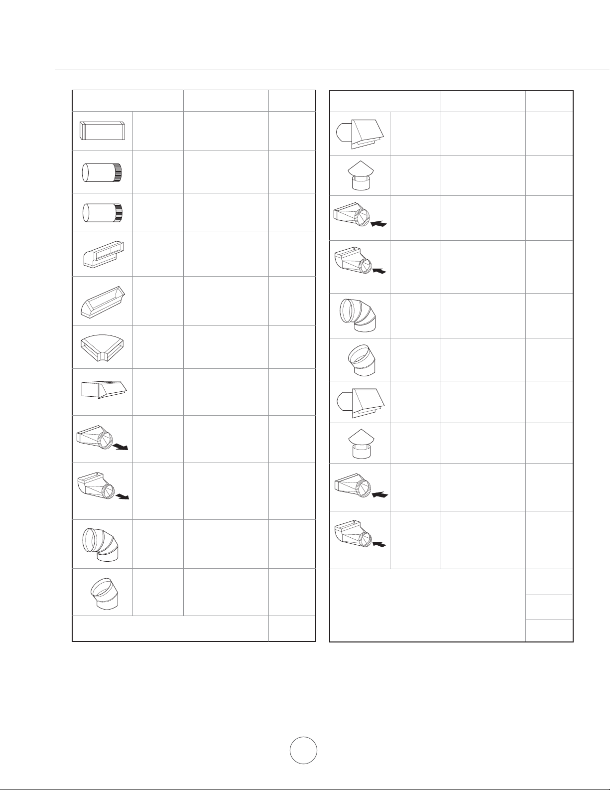
Installation - Ductwork Calculation S heet
6” Round,
0
90
elbow
6” Round,
0
elbow
45
Maximum Duct Length:
the total duct length ofa31/4”x10”rectangular, 6” or 7”
diameter round ductshould not exceed 100 equivalent feet.
15 Ft. x ( ) =
9 Ft. x ( ) =
Subtotal column 1 =
For satisfactory air movement,
Ft.
Ft.
Ft.
Ft.
Ft.
7” Round,
roof cap
7” round to
31/4”x10”
rect.
transition
7” round to
3 1/4” x 10”
rect.
transition
900elbow
30 Ft. x ( ) =
8 Ft. x ( ) =
15 Ft. x ( ) =
Subtotal column 2 =
Subtotal column 1 =
Total ductwork =
Ft.
Ft.
Ft.
Ft.
Ft.
Ft.
4
Page 7
”
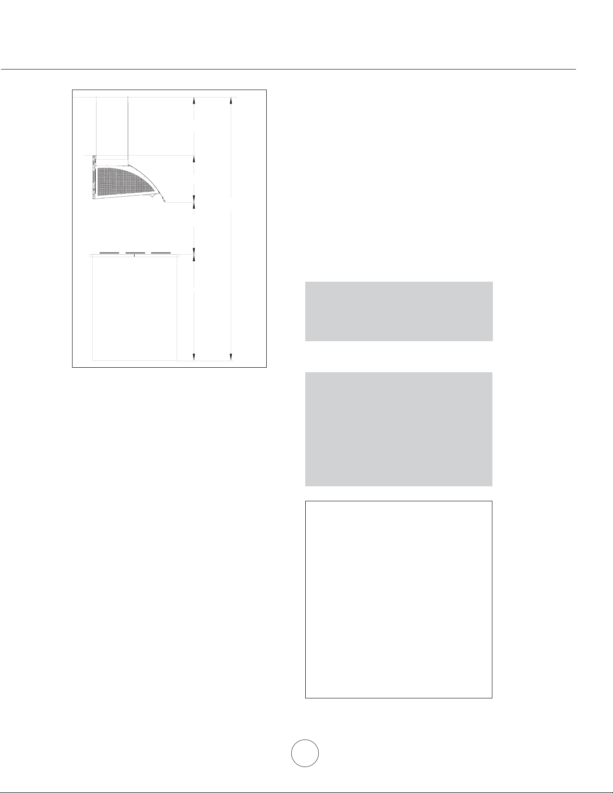
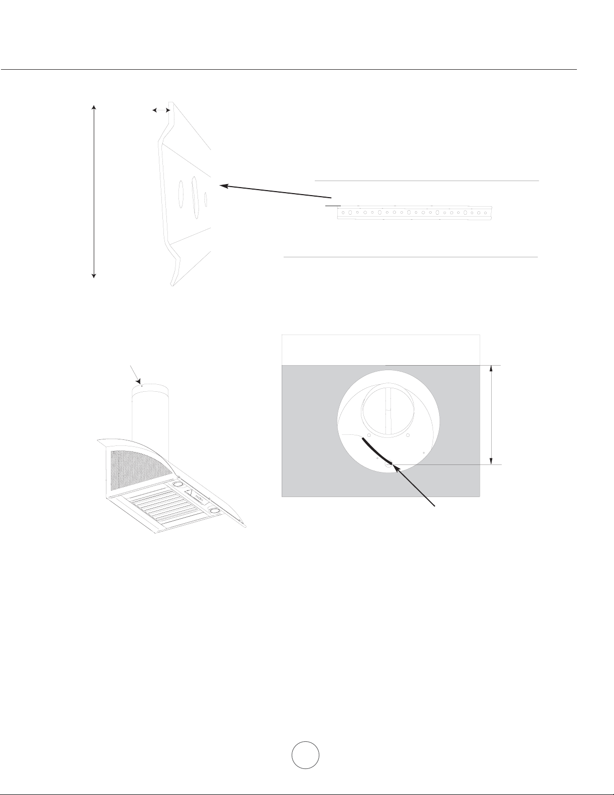
Minimum mount height between range top to hood bottom should be no less than 28".
Min 32"-Max 52"
14 1/2"
Min 96"-Max 124
Min 28"-Max 36"
36"
DUC T IN G
A minimum of 6” round or 3-1/4 x 10"
rectangular duct work must be used to maintain
maximum air ow eciency with the 600 cfm
internal blower. A minimum of 10"to 8” round
used with the 1000 cfm external blower.
Always use rigid type metal duct work only.
Flexible ducts could restrict air ow by up
to 50%.
Use calculation worksheet to compute total
duct work.
must be
Maximum mount height should be no higher than 36".
It is important to install the hood at the proper mounting
height. Hoods mounted too low could result in heat
damage and re hazard; while hoods mounted too high
will be hard to reach and will loose its performance and
eciency.
If available, also refer to range manufacturer's height
clearance requirements and recommended hood
mounting height above range. Always check your local
codes for any differences.
*Minimum ceiling height of 96”. Hood
mounted at 28” above cooking surface.
** Maximum ceiling height of 124". Hood
mounted at 36" above cooking surface.
Minimum Duct Size:
Round - 6” minimum at 600 cfm
Round - 10" to 8” minimum at 1000 cfm
Rect angular - 3 1/4” x 10” minimum only if
using internal blower at 600 cfm. Using
rectangular ductwork will require a transition
adapter (not provided, but readily available at
most hardware stores).
DAMAGE-SHIPMENT / INSTALLATION:
• Please fully inspect unit for damage
before installation.
Installation - Mounting Height & Clearance
ALWAYS, when possible, reduce the number
or transitions and turns. If a reducer is used,
install a long reducer instead of a pancake
reducer. Reduce duct size as far away from
opening as possible.
If turns or transitions are required:
Install as far away from opening and as far
apart, between 2, as possible.
• If the unit is damaged in shipment , return
the unit to the store in which it was bought
for repair or replacement.
If the unit is damaged by the customer ,
•
repair or replacement is the responsibility
of the customer.
• If the unit is damaged by the installer (if
other than the customer), repair of replace
ment must be made by arrangement
between customer and installer.
5
Page 8

www.zephyronline.com
WARNING FIRE HAZARD
NEVER exhaust air or terminate duct work into spaces between walls, crawl spaces, ceiling, attics, or garages. All exhaust must
be ducted to the outside.
Use single wall rigid Metal ductwork only.
Fasten all connections with sheet metal screws and tape all joints w/ certified Silver Tape or DuctTape.
Some Ducting Options:
Roof Pitch w/
Flashing & Cap
Installation - Ducting
side wall
cap with
gravity
damper
External
Blower
External
Blower
Soffit or crawl space
Soffit or crawl space
6
Page 9

19 3/4”
19 3/4”
10”
16 5/8”
13 3/8”
RIHPEZYBNGISEDGNEHCOGOL
95°
11 7/8”
14 1/2”
36”, 42”, 48”
22 5/8”
5" - 36 "
8" - 42"
31/2"-48"
6"
Installation - Specifications
15”
4/1
”
R
14
O
”8/37
”61/5
R
“1
8/
”
4
1
1
/
23
”
8 5/16”
9 3/16”
1
5
/
3
2
”
7
Page 10

www.zephyronline.com
ATTENTION
The following are intructions for installing internal blower model CBI-600. For instructions on preparing for external
blower model CBE-1000 please turn to page “10”. Before installing, verify that motor spins freely.
The internal blower kit consists of the blower
and capacitor box with wiring.
Installation - Internal Blower
2. Att ach blower to ange as shown using
the provided 1/2” 5x15mm screws with
washers.
1. Position blower as shown.
3. P osition capacitor box as shown.
4. Secure capacitor bo x to hood using the
provided 1/2” self tapping screws.
8
Page 11
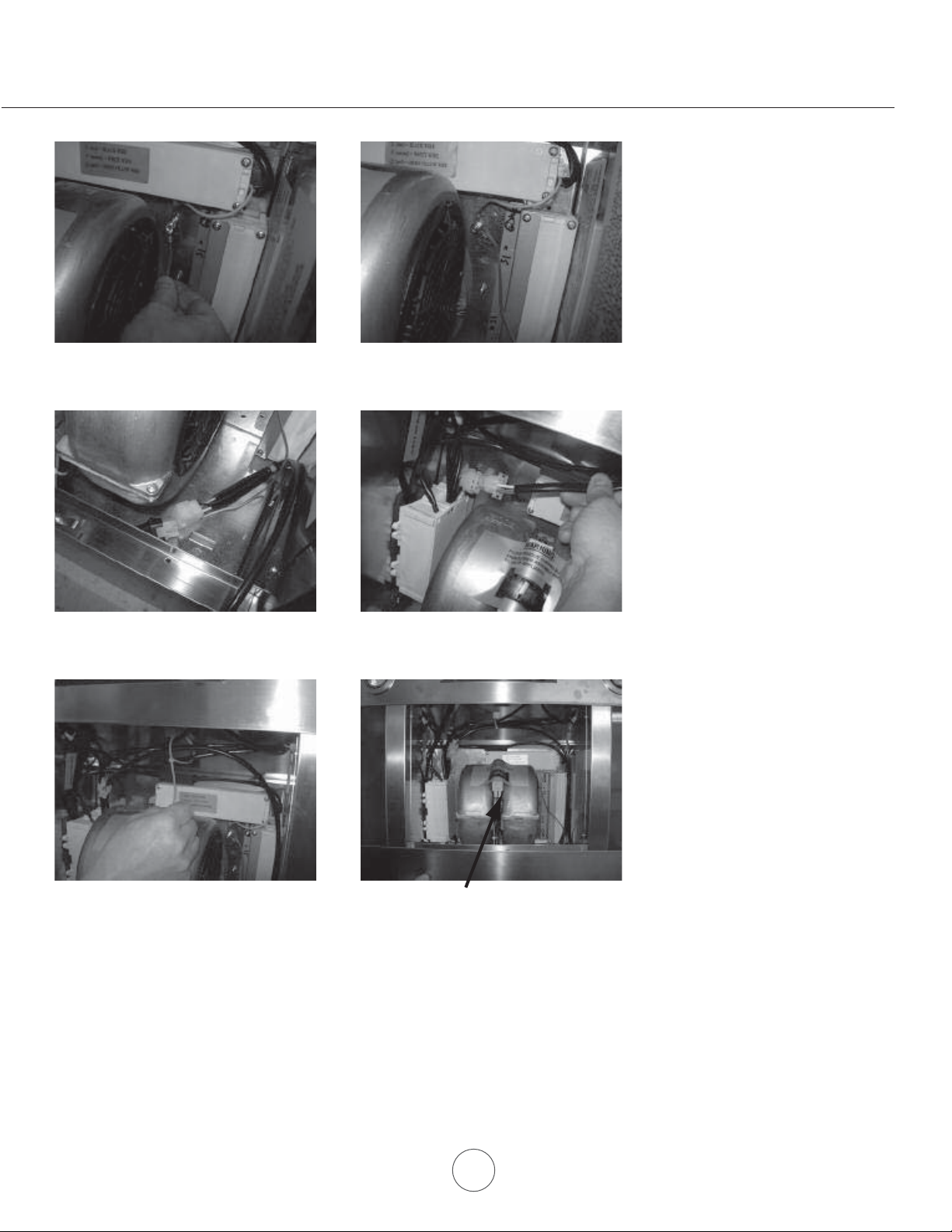
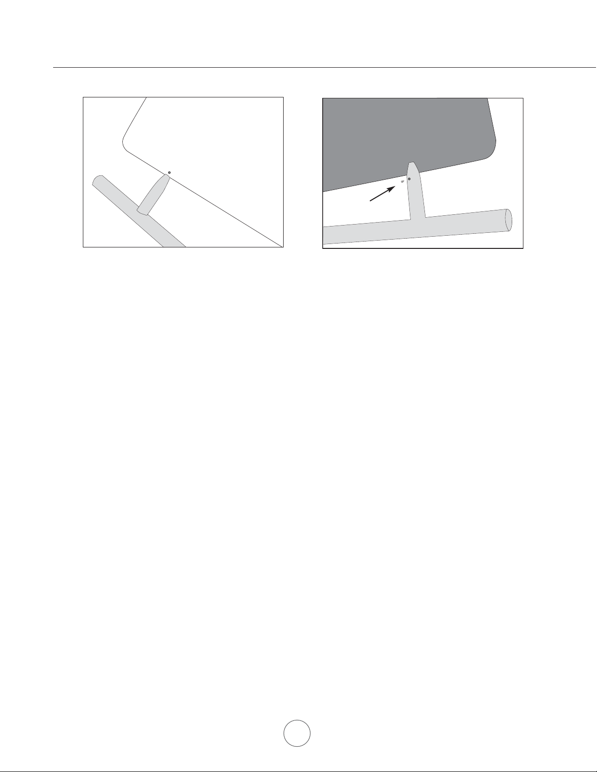
5. Remove existing grounding screw and
attach grounding wire from capacitor box.
7. Attach short capacitor connector to blower
connector.
6. Re-attach grounding screw to nish
installation of capacitor box. Refer to Fig-A on
previous page.
Installation - Internal Blower
8. Att ach long capacitor connector to control
board connector.
9. Use plastic tie to hold wiring together. 10. Remove wood block
Final view of internal blower install.
Continue to page “12” for hood installation instructions.
9
Page 12

www.zephyronline.com
ATTENTION
The following are intructions on preparing your hood for installation with external blower model CBE-1000.
For instructions on installing internal blower model CBI-600 please turn to page “8”.
NOTE: Please refer to the CBE-1000 manual for external blower mounting instructions.
The external blower kit consists of an 8”
collar, and external blower wiring box. The
external blower is purchased separately.
2. Remove internal ange from hood. 3. Position 8” collar as shown.
1. Remove screws from internal ange.
Installation - Preparing E xternal B lower
4. Att ach 8” collar to hood as shown using
provided 1/2” self t apping screws.
5. Attach external blower wiring box to top of
hood using provided 1/2” self t apping
screws.
10
Page 13

6. Position cover onto external blower
wiring box.
7. Secure cover to box with provided screw.
8. Attach connector from external blower
wiring box to control board box connector
inside hood.
10. Final view of external blower preparation
9. Attach grounding wire from external blower
wiring box to grounding screw of the junction
box. Refer on Fig-A in diagram below .
Installation - Preparing E xternal B lower
Continue to page “12” for hood installation instructions.
For external blower installation please refer to the manual
included with the external blower.
11
Page 14

Duct Cover
Ceiling Bracket
B
www.zephyronline.com
C/L
Duct Cover
Ceiling Bracket
-noitallatsnI dooHgniraperP
C
A
1. Measure from cooking surface to hood bottom, level and mark line A.
2. Plum and mark center line.
3. Mark mounting height, line B (14 1/2” from line A). This is the top of the hood.
21”
C/L
14 1/2”
7 1/2”
min 28”
max 36”
C/L
Attach screws to
ceiling bracket
4. Measure up, 7 1/2” from line A and mark mounting spread from C/L Line C. (21”)
5. Follow center line up to the ceiling, measure and mark 6” from the wall.
on the center line. This is where the
6. Place duct cover ceiling bracket onto ceiling and mark the (2) holes where screws will be attached. If attaching
bracket to drywall only, drill and insert provided anchors into the marked holes. Cut out inside diameter of the
ceiling bracket to fit the 6” or 8” round duct work. Attach bracket to ceiling with (2) screws provided.
7. Prepare duct work and electrical.
All Electrical work must be performed by a qualified electrician or person with similiar
GNINRAW-LACIRTCELE
technical know and background.
For personal safety, remore house fuse or open circuit beaker before beginning installation.
Do not use extension cords or adapter plug with this appliance.
Follow National Electrical Codes or prevailing local codes and ordinances.
Electrical Supply:
This appliance requires a 120V 60Hz electrical supply, and connected to an individual, properly grounded branch
circuit, protected by a 15 or 20 ampere cicuit breaker or time delay fuse. Wiring must be 2 wire with ground.
Please refer to Electrical Diagram labeled on product.
center of the duct cover ceiling bracket will mount.
Make sure the spot you mark is still
12
Page 15
Top
gap between
bracket and
wall
Bottom
Attach screws to both
sides of the duct covers
and secure to ceiling bracket.
B
C
A
10”
Electrical
1. Place wall brac
sure bracket is attached to wall as shown in the diagram. The top of the wall bracket should have a gap between
it and the wall. The bottomshould be ush against the wall. Use (3) 2” wood screws to attach bracket to wall. Use
anchors if not mountingto studs.
2. Lift hood onto wall bracket, there is a lip on the back of the hood which will rest on the wall bracket. Secure in
place by *screwing (2) screws with washers throughhood into the wall. There are two holes at the bottom inside
the hood in which to do this.
3. Place telescopic duct covers on top of hood and extend top duct cover to the ceiling bracket. Attach duct cover to
ceiling bracket with the providedscrews.
4. Run duct work down to top of motor. Attach electrical wiring from ceiling to wiringon top of motor housing. (slide
duct cover up towards ceiling to gain access to the motor housing)
ket on line C. Position top of wall bracket so it is even with the 21” mounting spread. Make
Installation - Mounting Hood
* Note: If installing onto drywall only with no wall studs present, attach E Z anchors (not provided) into the wall.
Please see page 15 for external blower installation instructions.
13
Page 16
www.zephyronline.com
Set
screw
kcaBtnorF
1. Attach utensil rail to hood canopy. A small hole has been pre-drilled into the canopy to provide a starting point
to attach the rst utensil rail post. After the rst post is lined up with the hole, gently slide the rest of the rail onto
the canopy. (note: be careful not to scratch the stainless steel when performing this step, this is why there is a
starter hole).
2. A ttach a short set screw into eac h post in order to hold utensil rail onto canopy.
Installation - Attaching Utensil Rail
14
Page 17
o
d
,
p
.
www.zephyronline.com
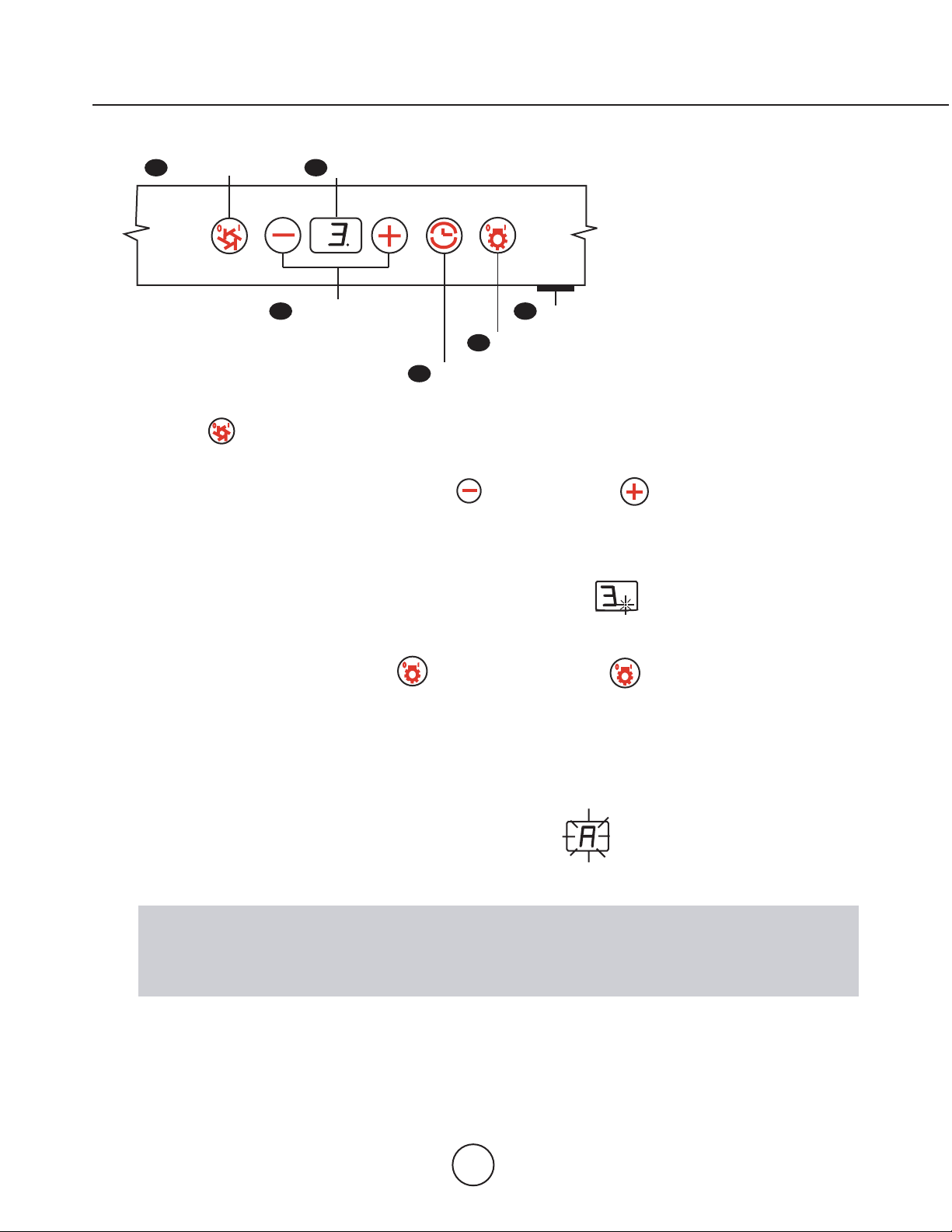
1
Blower On/Off
5
Display
2
Adjust 3 Speed Levels
(Speed level, Delay O Indicator, Filter Clean/Change)
6
Mood Light On/Off
4
Lights On/Off/Hold to Dim
3
15 Min Delay Off
1. Blower On/Off
By pressing , the blower is switched On and Off.
2. Speed Selection
The 3 speed levels are selected by pressing to decrease and to increase speed level.
The display indicates level selected.
3. Delay Off
This is used for programmed shut down of blower and lights 15 minutes after the function is activated.
Press once, a dot flashes in the lower right hand side of display indicating the function is on.
The hood will completely shut down in 15 minutes.
4. Lights On/Off/Dim
Switch lights On and Off by pressing once. T
im lights
ress again
5. Advance Display Functions
6. Mood Light On/Off
This switch turns the mood lights On and Off. Press IN to turn on, press again to turn OFF.
Filters Clean Reminder (Metal):
After every 30 hours of use, the display will start flashing an reminding you to clean the baffle
filters from residue and possible clogs.
Features & Controls - Touch Controls & Features
The standard Baffle Filters are required to be cleaned frequently and as recommended in order to maintain
blower efficiency. If improperly maintained, residue from cooking will sift through filters and cause damage to
hood blowers and other sensitive components; and possibly clog duct work and create a fire hazard.
15
Page 18

Filter Clean Reminder (Standard Bae Filters tted):
A set of bae lters are tted by the factory. These Bae Filters are intended to lter out residue from cooking. They
need not be replaced on a regular basis but are required to be kept clean. The Filter Clean Reminder function in
the microprocessor will automatically indicate by a ashing when the metal lters need to be cleaned after
every 30 hrs. of use. Filters can be cleaned by hand with non-abrasive soap or in a dishwasher.
Filter Clean Reminder:
When ashes on display, the bae
lters installed are required to be cleaned.
This will occur after every 30 hours of use.
Re-setting Function:
Reset the Filter Clean Reminder timer when
lters are cleaned and re-installed (with
hood o). Press and hold for approx.
5 seconds, the display will appear; hold for
approximately 5 seconds until on display disappears . The Filter Clean
Reminder function is now re-set and a new
30 hours elapse cycle is initiated.
Clean Filters
To Reset
hold 5 secs.
display <A> flashes
display from <C> to < >
16
Features & Controls - B affle Filters Change Indicator
Page 19

S
:
Clean
y
withhot
s
y
waterand
clean
cotto
ot
corrosive
orabrasive
t
,
orstee
l
ds
c
s
t
cand
d
.
er
so
.
A
fte
g,
youmay
e
sta
ess
stee
/
c
d
out
the
sta
ess
uster
and
g
ean
cotto
,
and
withthe
g
.
o
t
c
g
chlo
ea
cnot
s.
aeilters
he
f
y
are
d
to
lteroutresidue
and
g
y
eednot
d
on
a
s
are
d
to
.
lters
should
cleaned
afte
3
0rs
of
se.se
th
on
th
ls
tod
e
when
e
cl
e
lter
g
towards
u
and
e
and
clean
d
o
e
.
S
y
d
etosoak
d.
s
and
Should
lters
wear
out
due
to
age
and
www.zephyronline.co
m
”
urface
eriodicall
/scouringa
woo
Forheavi
rcleanin
rain. Alwaysscrubightlywithcl
D
B
eMetalFilterstted
n
t
require
i
u
contro
mov
pullingdown (Fig. 1).
aintenance
oap
cra
il
liquiddegreaser
n-abrasiv
anyroduc
replace
e
eptclean
eFilterCleaneminder function
etermin
slidin
ontainin
t
actor
reasefrom cooking.The
egular
revery
lters requir
rinel
i
yo
amagesurface
inl
ncloth
ntende
e
eaning.
ncloth.n
l polish
leaners,toolishan
“orange”cleaner
2 3/4
rain
detergen
inl
l
l
andles
mov
pra
egreasingdetergentandeav
eavilysoile
rylter
eplacingaeFilte
use, contact Zephyr to purchase replacements.
y
n
rindishwash
e-installbefore usingood.
s
Fig. 1)
Page 20

Replacing Light Bulbs:
CAUTION: Light bulbs become extremely hot when turned on. DO NOT touch bulbs until switched o
and cooled. Touching hot bulbs may cause serious burns.
Make sure all power is turned o and bulbs are not hot.
Remove bulb by pressing both ends of the metal retaining clip together, the light socket will now protudefrom the hood
allowingyou to remove the bulb.(B e careful when releasing retain clip as it is under pressure to hold it in place)
Replacement halogen bulbs are available at most stores which sell light bulbs. Purchase type GU-10, 120 V, 50 W.
Press together
to release clip
HalogenBulb
To replace mood lightingbulb, remove bae lter from hood. Lift up the metal plate which is inside the hood on the left
and right sides. It is held on with two philipshead screws. Unscrew mood lightingbulb counter-clockwise and replace
with a standard 4 0W, 125V-1 3 0V medium base bulb.
Maintenance - Lights
MetalPlate
MoodLightingBulb
18
Page 21
After installation, the unit
doesn’t work?
1. The power source is not turned ON.
2. The power line and the cable locking connector is
not connecting properly.
www.zephyronline.com
odottahWesuaCeussI
1. Make sure the circuit breaker and the unit’s
power is ON.
2. Check the power connection with the unit is
connected properly.
Light works, but motor is
not turning.
Trouble S hooting
The unit is vibrating.
The motor is working,
but the lights are not.
The hood is not venting
out properly.
3. The switch board and control board wirings
are disconnected.
4. On the switch board, Black/White wire of White
wire is disconnected.
5. The switch board or control board is defective.
1. The motor is defective, possible seized.
2. The thermally protected system detects if the motor
is too hot to operate and shuts the motor down.
3. Damaged capacitor.
1. The motor is not secure in place.
2. Damaged blower wheel/makes noise.
3. The hood is not secured in place.
1. Defective halogen bulb.
2. The light bulb is loose.
1. T he hood might be hanging too high from the
cook top.
2. The wind from the opened windows or opened
doors in the surrounding area are a ecting the
ventilation of the hood.
3. Blocking in the duct opening or ductwork.
4. The direction of duct opening is against the wind.
3. Make sure the wirings between the switch
board and control board are connected properly.
4. Make sure the Black/White wire or White wire
connects properly.
5. Change the switch board or control board.
1. Change the motor.
2. T he motor will function properly after the
thermally protected system cool down.
3. Change the capacitor.
1. Tighten the motor in place.
2. Change the motor.
3. Check the installation of the hood.
1. Change the halogen bulb.
2. Tighten the light bulb.
1. Adjust the distance between the cook top
and the bottom of the hood within 24” and
32” range.
2. Close all the windows and doors to eliminate the
outside wind ow.
3. Remove all the blocking from the duct work or
duct opening.
4. Adjust the duct opening direction.
Filter is vibrating.
After hood has been
installed for a period of
time, it stopped working.
5. Using the wrong size of ducting.
1. Bae lter is loose.
1. Control board needs to be reset.
1. Defective control board.
5. Change the ducting to at least 6” or higher
for the internal blower and 8” or higher for the
external blower.
1. Remove lter and reinstall it or change the
bae lter.
1. Turn circuit breaker which controls the hood o
for at least 15 minutes.
Turn it back on and this should x the problem.
1. Replace control b oard.
19
Page 22

Part Description Part#
Halogen Bulb G U-10, 120V, 50W Z0B-0020
Incadescent Bulb T29 127V 40 W Z0B-0003
Accessory Description Part#
Internal Blower, 600 cfm CBI-600
External Blower, 1000 cfm CBE-1000
Duct Cover Extension Kit Z1C-00OK
www.zephyronline.com
List of Parts and Accessories
20
Page 23

www.zephyronline.com
TO OBTAIN SERVICE UNDER WARRANTY
or any Service Related Questions, please call:
1-888-880-8368
Staple your receipt here.
Proof of the original purchase
date is needed to obtain service
under the warranty.
Warranty
TO OBTAIN SERVICE UNDER WARRANTY: You must present proof of original purchase date.
Please keep a copy of your dated proof of purchase (sales slip) in order to obtain service under warranty.
One Year Service Repair Warranty:
For one year from date of original purchase, we will provide free of charge, service labor to repair any failed parts or
components due to manufacturing defects.
Two Years Parts Warranty:
For two years from date of original purchase, we will provide free of charge, nonconsumable replacement parts or
components that failed due to manufacturing defects. Consumable parts not covered by this warranty include: Light Bulbs,
Metal and Charcoal Filters.
Who is Covered:
This warranty is extended to the original purchaser for products purchased for ordinary home use in the 48 mainland states,
Hawaii and Washington D.C. In Canada and Alaska, this warranty is Limited. There might be costs associated with
shipping the products to our designated service locations or you might need to pay service technician's travel costs, to have
the appliance repaired in-home.
This Warranty will be Voided when:
Product damaged through negligence, misuse, abuse, accident. Improper installation and failure to follow installation instructions. When product is used commercially or other than its intended purpose. Damaged because of improper connection with
equipment of other manufacturers. Repaired or modified by anyone other than Zephyr's Authorized Agents.
What is Not Covered:
Consumable parts such as light bulbs, filters, and fuses. Services outside of service area and the labor cost incurred in
connection with the removal, shipping and reinstallation cost, nor does it cover any other contingent expenses. The natural
wear of finish, and wear due to improper maintenance, use of corrosive and abrasive cleaning products, pads, and oven
cleaner products. Chips, dents or cracks due to abuse, misuse, freight damage, or improper installation. Service trips to your
home to teach you how to use the product. Damage of product caused by accident, fire, floods or act of God.
This warranty is valid in the United States and Canada. It is non-transferable and applies only to the original purchaser and
does not extend to subsequent owners of this product. Any applicable implied waranties, including the warranty of
merchantability, are limited in duration to a period of express warranty as provided herein beginning with the date of original
purchase at retail
Have your product proof of purchase with date ready for warranty issues.
Or write to:
and, no warranties, whether express or implied, shall apply to this product thereafter.
Zephyr Corporation
Service and Warranty Department
395 Mendell Street
San Francisco, CA 94124
JAN07.0101
 Loading...