

Page 1

© Copyright 2003, Zenith Electronics Corporation.
Installation and Operating Guide | Warranty
Model Number | C34W37 | Direct View TV
Page 2

PAGE 2
206-03890
WARNING:
TO REDUCE THE RISK OF ELECTRIC SHOCK DO NOT REMOVE COVER (OR BACK). NO USER SERVICEABLE PARTS INSIDE.
REFER TO QUALIFIED SERVICE PERSONNEL.
The lightning flash with arrowhead symbol, within an equilateral triangle, is intended to alert the user to the presence
of uninsulated “dangerous voltage” within the product’s enclosure that may be of sufficient magnitude to constitute a
risk of electric shock to persons.
The exclamation point within an equilateral triangle is intended to alert the user to the presence of important operating
and maintenance (servicing) instructions in the literature accompanying the appliance.
WARNING:
TO PREVENT FIRE OR SHOCK HAZARDS, DO NOT EXPOSE THIS PRODUCT TO RAIN OR MOISTURE.
POWER CORD POLARIZATION:
CAUTION: TO PREVENT ELECTRIC SHOCK, MATCH WIDE BLADE OF PLUG TO WIDE SLOT, FULLY INSERT.
ATTENTION: POUR ÉVITER LES CHOCS ÉLECTRIQUES, INTRODUIRE LA LAME LA PLUS LARGE DE LA FICHE DANS LA BORNE
CORRESPONDANTE DE LA PRISE ET POUSSER JUSQU’AU FOND.
NOTE TO CABLE/TV INSTALLER:
This reminder is provided to call the CATV system installer’s attention to Article 820-40 of the National Electric Code
(U.S.A.). The code provides guidelines for proper grounding and, in particular, specifies that the cable ground shall be
connected to the grounding system of the building, as close to the point of the cable entry as practical.
REGULATORY INFORMATION:
This equipment has been tested and found to comply with the limits for a Class B digital device, pursuant to Part 15 of
the FCC Rules. These limits are designed to provide reasonable protection against harmful interference when the equipment is operated in a residential installation. This equipment generates, uses and can radiate radio frequency energy
and, if not installed and used in accordance with the instruction manual, may cause harmful interference to radio communications. However, there is no guarantee that interference will not occur in a particular installation. If this equipment does cause harmful interference to radio or television reception, which can be determined by turning the equipment off and on, the user is encouraged to try to correct the interference by one or more of the following measures:
• Reorient or relocate the receiving antenna.
• Increase the separation between the equipment and receiver.
• Connect the equipment into an outlet on a circuit different from that to which the
receiver is connected.
• Consult the dealer or an experienced radio/TV technician for help.
Any changes or modifications not expressly approved by the party responsible for compliance could void the user’s
authority to operate the equipment.
COMPLIANCE:
The responsible party for this product’s compliance is:
Zenith Electronics Corporation, 2000 Millbrook Drive, Lincolnshire, IL 60069, USA
Digital TV Hotline:
1-847-941-8000
CAUTION:
Do not attempt to modify this product in any way without written authorization from Zenith Electronics Corporation.
Unauthorized modification could void the user’s authority to operate this product.
2003 Zenith Electronics Corporation. All rights reserved.
WARNING
RISK OF ELECTRIC SHOCK
DO NOT OPEN
Page 3

PAGE 3
206-03890
Important safeguards for you and your new product
Your product has been manufactured and tested with your safety in mind. However, improper use can result in electrical
shock or fire hazards. To avoid defeating the safeguards that have been built into your new product, please read and
observe the following safety points when installing and using your new product, and save them for future reference.
Observing the simple precautions discussed in this manual can help you get many years of enjoyment and safe operation
that are built into your new product.
This product complies with all applicable U.S. Federal safety requirements, and those of the Canadian Standards Association.
(Continued on next page)
1. Read Instructions
All the safety and operating instructions should be read
before the product is operated.
2. Follow Instructions
All operating and use instructions should be followed.
3. Retain Instructions
The safety and operating instructions should be retained
for future reference.
4. Heed Warnings
All warnings on the product and in the operating instructions should be adhered to.
5. Cleaning
Unplug this product from the wall outlet before cleaning.
Do not use liquid cleaners or aerosol cleaners. Use a damp
cloth for cleaning.
6. Water and Moisture
Do not use this product near water, for example, near a
bath tub, wash bowl, kitchen sink, or laundry tub, in a
wet basement, or near a swimming pool.
7. Accessories, Carts, and Stands
Do not place this product on a slippery or tilted surface,
or on an unstable cart, stand, tripod, bracket, or table.
The product may slide or fall, causing serious injury to a
child or adult, and serious damage to the product. Use
only with a cart, stand, tripod, bracket, or table recommended by the manufacturer, or sold with the product.
Any mounting of the product should follow the manufacturer’s instructions, and should use a mounting accessory
recommended by the manufacturer.
8. Transporting Product
A product and cart combination should be moved with
care. Quick stops, excessive force, and uneven surfaces
may cause the product and cart combination to overturn.
9. Attachments
Do not use attachments not recommended by the product
manufacturer as they may cause hazards.
10. Ventilation
Slots and openings in the cabinet are provided for ventilation and to ensure reliable operation of the product and to
protect it from overheating, and these openings must not
be blocked or covered. The openings should never be
blocked by placing the product on a bed, sofa, rug, or
other similar surface. This product should not be placed in
a built-in installation such as a bookcase or rack unless
proper ventilation is provided or the manufacturer’s
instructions have been adhered to.
11. Power Sources
This product should be operated only from the type of
power source indicated on the marking label. If you are
not sure of the type of power supply to your home, consult your product dealer or local power company. For products intended to operate from battery power, or other
sources, refer to the operating instructions.
12. Power-Cord Polarization
This product is equipped with a polarized alternating-current line plug (a plug having one blade wider than the
other). This plug will fit into the power outlet only one
way. This is a safety feature. If you are unable to insert
the plug fully into the outlet, try reversing the plug. If
the plug should still fail to fit, contact your electrician to
replace your obsolete outlet. Do not defeat the safety purpose of the polarized plug.
13. Power-Cord Protection
Power-supply cords should be routed so that they are not
likely to be walked on or pinched by items placed upon or
against them, paying particular attention to cords at
plugs, convenience receptacles, and the point where they
exit from the product.
PORTABLE CART WARNING
IMPORTANT SAFETY INSTRUCTIONS
Page 4

PAGE 4
206-03890
(Continued from previous page)
14. Outdoor Antenna Grounding
If an outside antenna or cable system is connected to the
product, be sure the antenna or cable system is grounded
to provide protection against voltage surges and built-up
static charges. Article 810 of the National Electrical Code
(U.S.A.), ANSI/ NFPA 70 provides information with regard
to proper grounding of the mast and supporting structure,
grounding of the lead-in wire to an antenna discharge
unit, size of grounding conductors, location of antennadischarge unit, connection to grounding electrodes, and
requirements for the grounding electrode.
15. Lightning
For added protection for this product (receiver) during a
lightning storm, or when it is left unattended and unused
for long periods of time, unplug it from the wall outlet and
disconnect the antenna or cable system. This will prevent
damage to the product due to lightning and power-line
surges.
16. Power Lines
An outside antenna system should not be located in the
vicinity of overhead power lines or other electric light or
power circuits, or where it can fall into such power lines or
circuits. When installing an outside antenna system,
extreme care should be taken to keep from touching such
power lines or circuits as contact with them might be
fatal.
17. Overloading
Do not overload wall outlets and extension cords as this
can result in a risk of fire or electric shock.
18. Object and Liquid Entry
Never push objects of any kind into this product through
openings as they may touch dangerous voltage points or
short-out parts that could result in a fire or electric shock.
Never spill liquid of any kind on the product.
19. Servicing
Do not attempt to service this product yourself as opening
or removing covers may expose you to dangerous voltage
or other hazards. Refer all servicing to qualified service
personnel.
20. Damage Requiring Service
Unplug this product from the wall outlet and refer servicing to qualified service personnel under the following conditions:
a. If the power-supply cord or plug is damaged.
b. If liquid has been spilled, or objects have fallen into
the product.
c. If the product has been exposed to rain or water.
d. If the product does not operate normally by following
the operating instructions. Adjust only those controls that
are covered by the operating instructions as an improper
adjustment of other controls may result in damage and will
often require extensive work by a qualified technician to
restore the product to its normal operation.
e. If the product has been dropped or the cabinet has
been damaged.
f. If the product exhibits a distinct change in performance.
21. Replacement Parts
When replacement parts are required, be sure the service
technician has used replacement parts specified by the
manufacturer or have the same characteristics as the original part. Unauthorized substitutions may result in fire,
electric shock, or other hazards.
22. Safety Check
Upon completion of any service or repairs to this product,
ask the service technician to perform safety checks to
determine that the product is in proper operating condition.
23. Wall or Ceiling Mounting
The product should be mounted to a wall or ceiling only as
recommended by the manufacturer. The product may slide
or fall, causing serious injury to a child or adult, and serious damage to the product.
24. Heat
The product should be situated away from heat sources
such as radiators, heat registers, stoves, or other products
(including amplifiers) that produce heat.
Antenna Lead in Wire
Antenna Discharge Unit
(NEC Section 810-20)
Grounding Conductor
(NEC Section 810-21)
Ground Clamps
Power Service Grounding
Electrode System (NEC
Art 250, Part H)
Ground Clamp
Electric Service
Equipment
Example of Grounding According to National Electrical
Code Instructions
Fig. 1
NEC - National Electrical Code
IMPORTANT SAFETY INSTRUCTIONS
Page 5

PAGE 5
206-03890
Table of Contents
Safety Warnings . . . . . . . . . . . . . . . . . . . . . . . . . . . .2
Important Safety Instructions . . . . . . . . . . . . . . . . .3-4
Step 1. Hook Up TV
Front Panel Controls . . . . . . . . . . . . . . . . . . . . . . . . .6
Rear Connections Panel . . . . . . . . . . . . . . . . . . . . . . .7
Front Connections Panel (Front Video) . . . . . . . . . . . . .8
ANT/Cable Service Hookup . . . . . . . . . . . . . . . . . . . . .9
Cable Box Connections . . . . . . . . . . . . . . . . . . . . . . .10
VCR Connections . . . . . . . . . . . . . . . . . . . . . . . . . . .11
DVD Player . . . . . . . . . . . . . . . . . . . . . . . . . . . . . .12
Set-top Box Hookup . . . . . . . . . . . . . . . . . . . . . . . .13
Monitor Out Setup . . . . . . . . . . . . . . . . . . . . . . . . .14
External Stereo . . . . . . . . . . . . . . . . . . . . . . . . . . .15
Digital Audio Output . . . . . . . . . . . . . . . . . . . . . . . .16
Turning the TV on . . . . . . . . . . . . . . . . . . . . . . . . . .17
On-Screen Displays . . . . . . . . . . . . . . . . . . . . . . . . .17
Remote Control Functions in TV Mode . . . . . . . . . . .18-19
Step 2. Customize your TV’s Features
SETUP Menu
EZ Scan (Channel Search) . . . . . . . . . . . . . . . . . .20-21
Channel Edit . . . . . . . . . . . . . . . . . . . . . . . . . . . .22
DTV Signal . . . . . . . . . . . . . . . . . . . . . . . . . . . . . .23
Channel Label Setup . . . . . . . . . . . . . . . . . . . . . . .24
Main Picture Source Selection . . . . . . . . . . . . . . . . . 25
PIP (Picture-In-Picture) Options . . . . . . . . . . . . .26-27
POP (Picture-out-of-Picture) Source . . . . . . . . . . . . .28
Multi Point Zooming . . . . . . . . . . . . . . . . . . . . . . .28
Twin Picture . . . . . . . . . . . . . . . . . . . . . . . . . . . .29
VIDEO Menu
EZ Picture . . . . . . . . . . . . . . . . . . . . . . . . . . . . . .30
Manual Video Control . . . . . . . . . . . . . . . . . . . . . . .31
Color Temperature . . . . . . . . . . . . . . . . . . . . . . . . .32
Z-View . . . . . . . . . . . . . . . . . . . . . . . . . . . . . . . .32
Video Preset . . . . . . . . . . . . . . . . . . . . . . . . . . . .32
AUDIO Menu
Audio Language . . . . . . . . . . . . . . . . . . . . . . . . . .33
EZ SoundRite . . . . . . . . . . . . . . . . . . . . . . . . . . . .33
Stereo/SAP Broadcasts Setup . . . . . . . . . . . . . . . . . .34
EZ Sound . . . . . . . . . . . . . . . . . . . . . . . . . . . . . .34
Manual Sound Control . . . . . . . . . . . . . . . . . . . . . .35
Turn TV Speakers on/off . . . . . . . . . . . . . . . . . . . . .35
Front Surround . . . . . . . . . . . . . . . . . . . . . . . . . . .36
TIME Menu
Auto Clock Setup . . . . . . . . . . . . . . . . . . . . . . . . .37
Manual Clock Setup . . . . . . . . . . . . . . . . . . . . . . . .38
TV Turn Off Time Setup . . . . . . . . . . . . . . . . . . . . .39
TV Turn On Time Setup . . . . . . . . . . . . . . . . . . . . . .40
Sleep Timer Setup . . . . . . . . . . . . . . . . . . . . . . . . .41
Auto off . . . . . . . . . . . . . . . . . . . . . . . . . . . . . . .42
OPTION Menu
Aspect Ratio Control . . . . . . . . . . . . . . . . . . . . . . .43
Closed Captions . . . . . . . . . . . . . . . . . . . . . . . .44-45
Caption Option Menu . . . . . . . . . . . . . . . . . . . . . . .46
On-Screen Menus Language . . . . . . . . . . . . . . . . . . .47
Velocity Modulation . . . . . . . . . . . . . . . . . . . . . . . .47
Tilt . . . . . . . . . . . . . . . . . . . . . . . . . . . . . . . . . .48
Degaussing the screen . . . . . . . . . . . . . . . . . . . . . .48
EZ Demo . . . . . . . . . . . . . . . . . . . . . . . . . . . . . . .49
LOCK Menu
Parental Lock Setup . . . . . . . . . . . . . . . . . . . . .50-51
Step 3. Miscellaneous
Programming the Remote . . . . . . . . . . . . . . . . . . . . .52
Programming Codes . . . . . . . . . . . . . . . . . . . . . .53-56
Maintenance . . . . . . . . . . . . . . . . . . . . . . . . . . .57-58
Troubleshooting . . . . . . . . . . . . . . . . . . . . . . . . .59-60
Glossary . . . . . . . . . . . . . . . . . . . . . . . . . . . . . .61-62
Product Specifications . . . . . . . . . . . . . . . . . . . . . .63
Warranty . . . . . . . . . . . . . . . . . . . . . . . . . .Back cover
Note: Design and specifications are subject to change without prior notice.
Page 6
PAGE 6
206-03890
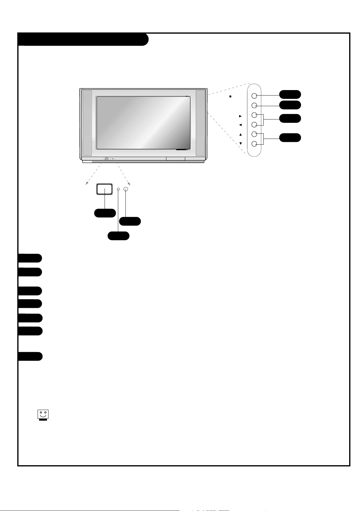
Front Panel Controls
menu
vol
ch
tv/video
power
Power
Standby indicator (Illuminates brightly when the TV is
in standby mode. Dims when the TV is switched on.)
Remote control sensor
TV/VIDEO
Menu
VOL LEFT / RIGHT
Volume(
G) button increases the sound level and vol-
ume(
F) button decreases the sound level.
CH (Channel) UP / DOWN
1
2
3
4
Th
es
1
2
3
5
6
7
4
5
6
7
Page 7
PAGE 7
206-03890
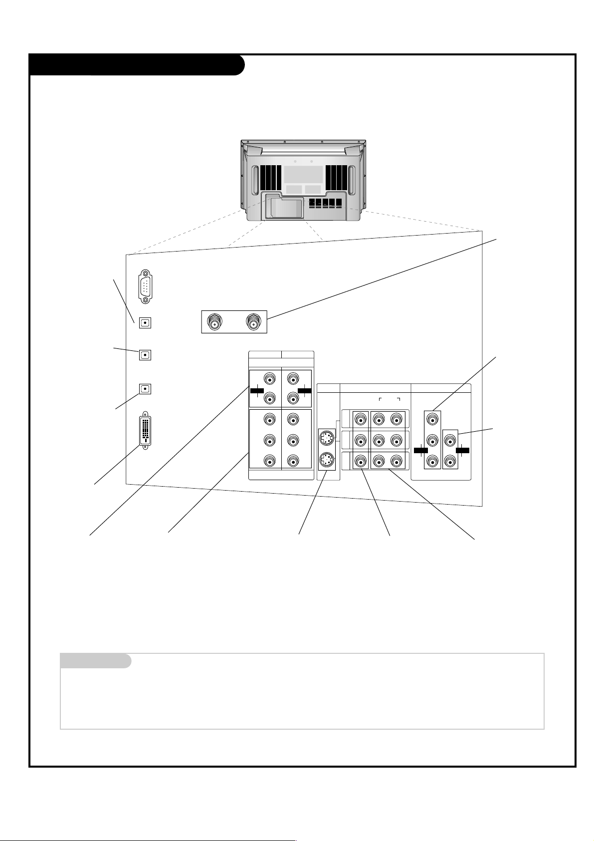
Rear Connections Panel
Mini glossary
JACK A connection on the back of a TV, VCR, or any other A/V device. This includes the RF jack and the Audio/Video jacks that are color-
coded.
SIGNAL Picture and sound traveling through cable, or over the air, to your television screen.
CALIBRATION
DIGITAL
AUDIO OUTPUT
OPTICAL
DVD/DTV INPUT
VIDEO
VIDEO
AUDIO
L(MONO) R
ANTENNA 1 ANTENNA 2
DVI-HDTV INPUT
DIGITAL
AUDIO INPUT1
OPTICAL
(COMPONENT1)
DIGITAL
AUDIO INPUT2
OPTICAL
(DVI)
PR
COMPONENT1
(480i/480p/720p/1080i)
COMPONENT2
S-VIDEO VIDEO/AUDIO INPUT MONITOR OUTPUT
VARIABLE
AUDIO
PB
Y
L
R
IN1
IN2
IN3
AUDIO
P
R
PB
Y
L
R
AUDIO
R
L
AUDIO
R
L
AUDIO
+75 Ω +75 Ω
S-Video In
A connection available
with some high-end
equipment that provides
even better picture
quality for Video 1, 2.
RF Connectors:
Antenna 1 Input,
Antenna 2 Input
Used to connect
cable or antenna signals to the television,
either directly or
through your cable
box.
Video 1, 2 and 3 Inputs
Connects the video signals
from various types of
equipment.
Y, P
B, PR
DVD Component Video and HD
Component Video
Some top-of-the-line DVD players use
what is called “component video,” for
extremely accurate picture reproduction. Refer to your DVD manual for
further information.
Connecting external equipment to your TV.
Monitor Out
Connects to a second
TV or Monitor.
Left/Right Audio
Used for stereo sound
from various types of
equipment.
Component Left/Right
Audio
Used for stereo sound from
various types of equipment.
Variable Audio Out
Used to connect
either an external
amplifier, or add a
sub-woofer to your
surround sound system.
DVI-HDTV Input
Used to connect
from a DTV source.
Digital Audio
Output Optical
Connects to external
audio equipment
like a home theater
system.
Digital Audio
Input1 Optical
Connects to digital
audio from various
types of equipment.
Digital Audio
Input2 Optical
Used in audio
connection from a
DTV source.
Page 8
PAGE 8
206-03890
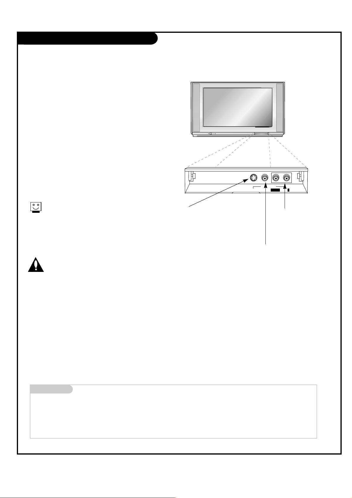
Front Connections Panel (Front Video)
S-Video Video in
Front Video
AudioL/mono
R
There are four jacks on the lower-right front
side of your TV that make connecting
Audio/Video devices like video games and
camcorders very simple.
The jacks are like those found on the back
jack connection panel. This means that most
equipment that connects to those types of
jacks on the rear jackpack, may be connected
to the front connection panel (Front Video).
To use the front jacks as the signal source,
select them using Main input menu as
described on page 25. They will be named
“Front Video” in the Main input menu.
Left/Right Audio
Used for stereo sound
from various types of
equipment.
Video in
Connects the video
signals from any
piece of equipment.
S-Video
A connection available on some very
high-end equipment that provides
better picture quality than video
input.
Wh
Mini glossary
A/V CABLES Audio/Video cables. Three cable connector—Right audio (red), Left audio (white), and Video (yellow). A/V cables are used for stereo
playback of videocassettes and for higher quality picture and sound from other A/V devices.
A/V DEVICE Any device that produces video (picture) and/or audio (sound) (VCR, DVD, cable box, or television).
Page 9

PAGE 9
206-03890
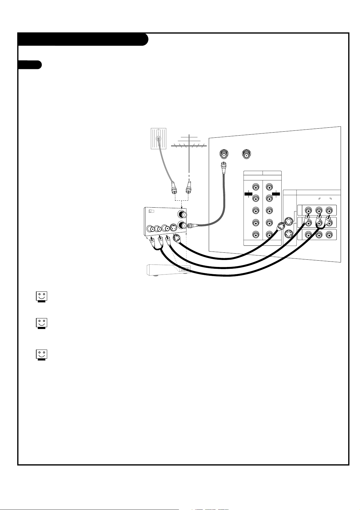
Antenna / Cable Service Hookup
1
Connect an antenna and/or cable service to
your TV as shown.
Turn to page 20 to do a channel search
with EZ Scan.
For best signal reception, it is recommended to have your Antenna professionally adjusted.
2
I
f
you
rec
e
iv
e
your
R
F
signal
through an
CALIBRATION
DIGITAL
AUDIO OUTPUT
OPTICAL
ANTENNA 1 ANTENNA 2
DIGITAL
AUDIO INPUT1
OPTICAL
(COMPONENT1)
+75 Ω +75 Ω
Antenna
Cable TV
Wall jack
RF coaxial wire
(75 ohm)
RF coaxial wire
(75 ohm)
Mini glossary
TV OVER-THE-AIR SIGNALS DTV DIGITAL OVER-THE-AIR SIGNALS
CATV CABLE SIGNALS CADTV DIGITAL CABLE SIGNALS
Combined signals
TV/CATV/DTV Over-the-air, cable, and digital over-the-air signals
TV/CATV/CADTV Over-the-air, cable, and digital cable signals
CAUTION : If you are not sure of the type of signal(s) you are receiving, let EZ Scan complete all the channel signal-type searches. The TV will let
you know when the analog, cable, and digital channel scans are complete.
Page 10

PAGE 10
206-03890
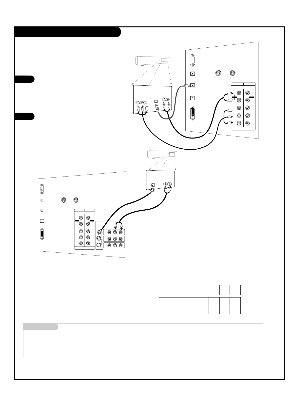
Cable Box Connections
I
f
you’r
Locate the output jack on the back of
your cable box. Connect this to the
Antenna 1 jack on the back of your TV.
Or find the composite video and audio
jacks on the back of your cable box, and
connect them following the instructions
provided with your equipment.
This can be combined with any other
equipment you may want to hook up.
1
In
Output
Switch
Out
Audio
TV
VCR
L
R
Video
3 4
DVD/DTV INPUT
VIDEO
AUDIO
L(MONO) R
ANTENNA 1 ANTENNA 2
PR
COMPONENT1
(480i/480p/720p/1080i)
COMPONENT2
S-VIDEO VIDEO/AUDIO INPUT
P
B
Y
L
R
IN1
IN2
IN3
AUDIO
P
R
PB
Y
L
R
AUDIO
+75 Ω +75 Ω
Cable box
RF coaxial wire
(75 ohm)
Cable box
Back AV panel
Page 11
PAGE 11
206-03890
VCR Connections
1
Locate the Antenna 1 jack on the
back of your TV. Connect this to
out jack on the back of your VCR.
Or find the composite video and
audio jacks on the back of your
VCR, and connect them following
the instructions provided with
your equipment.
You may connect either the composite video or the S-Video cables
to your TV. (Do not connect BOTH
the composite and the S- Video
cables. In the event that you connect both composite and the SVideo cables, only the S-Video will
work.)
To
hear
ster
I
f
you want to
rec
Aft
er
conn
In
Out
Audio
L
R
Video
3 4
S-Video
Output
Switch
DVD/DTV INPUT
VIDEO
AUDIO
L(MONO) R
ANTENNA 1 ANTENNA 2
PR
COMPONENT1
(480i/480p/720p/1080i)
COMPONENT2
S-VIDEO VIDEO/AUDIO INPUT
P
B
Y
L
R
IN1
IN2
IN3
AUDIO
P
R
PB
Y
L
R
AUDIO
+75 Ω +75 Ω
RF coaxial wire
(75 ohm)
A/V cables
not included
with TV
or
VCR
Back AV panel
Page 12
PAGE 12
206-03890
DVD Player
Mini glossary
COMPONENT VIDEO Some video equipment uses three separate lines (Y, P
B, PR) to more precisely reproduce images. Your manual will explain how
this relates to your equipment.
1
2
R
Audio
LR
S-Video
CALIBRATION
DIGITAL
AUDIO OUTPUT
OPTICAL
DVD/DTV INPUT
VIDEO
AUDIO
L(MONO) R
ANTENNA 1 ANTENNA 2
DVI-HDTV INPUT
DIGITAL
AUDIO INPUT1
OPTICAL
(COMPONENT1)
DIGITAL
AUDIO INPUT2
OPTICAL
(DVI)
PR
COMPONENT1
(480i/480p/720p/1080i)
COMPONENT2
S-VIDEO VIDEO/AUDIO INPUT
P
B
Y
L
R
IN1
IN2
IN3
AUDIO
P
R
PB
Y
L
R
AUDIO
+75 Ω +75 Ω
Component input jacks
on the TV
Y
PB
PR
Video output jacks
of DVD player
Y
Y
Y
Y
Pb
B-Y
Cb
PB
Pr
R-Y
Cr
P
R
• Component Input ports
You can get better picture quality if you
connect DVD player with component input
ports as below.
A/V cables
not included
with TV
DVD player
Back AV panel
or
Back AV panel
Find the component or S-Video
jacks for video connections,
depending on your DVD connectors. Then make the corresponding audio connections. See the
diagram for either set up.
You may connect either the
composite video or the S-Video
cables to your TV. Do not connect both the composite and
the S-Video.
CALIBRATION
DIGITAL
AUDIO OUTPUT
OPTICAL
ANTENNA 1 ANTENNA 2
DVI-HDTV INPUT
DIGITAL
AUDIO INPUT1
OPTICAL
(COMPONENT1)
DIGITAL
AUDIO INPUT2
OPTICAL
(DVI)
DVD/DTV INPUT
P
R
COMPONENT1
(480i/480p/720p/1080i)
COMPONENT2
PB
Y
L
R
AUDIO
P
R
PB
Y
L
R
AUDIO
Audio
LR
Digital Audio
Optical
Component Video
+75 Ω +75 Ω
DVD player
or
A/V cables
not included
with TV
Page 13
PAGE 13
206-03890
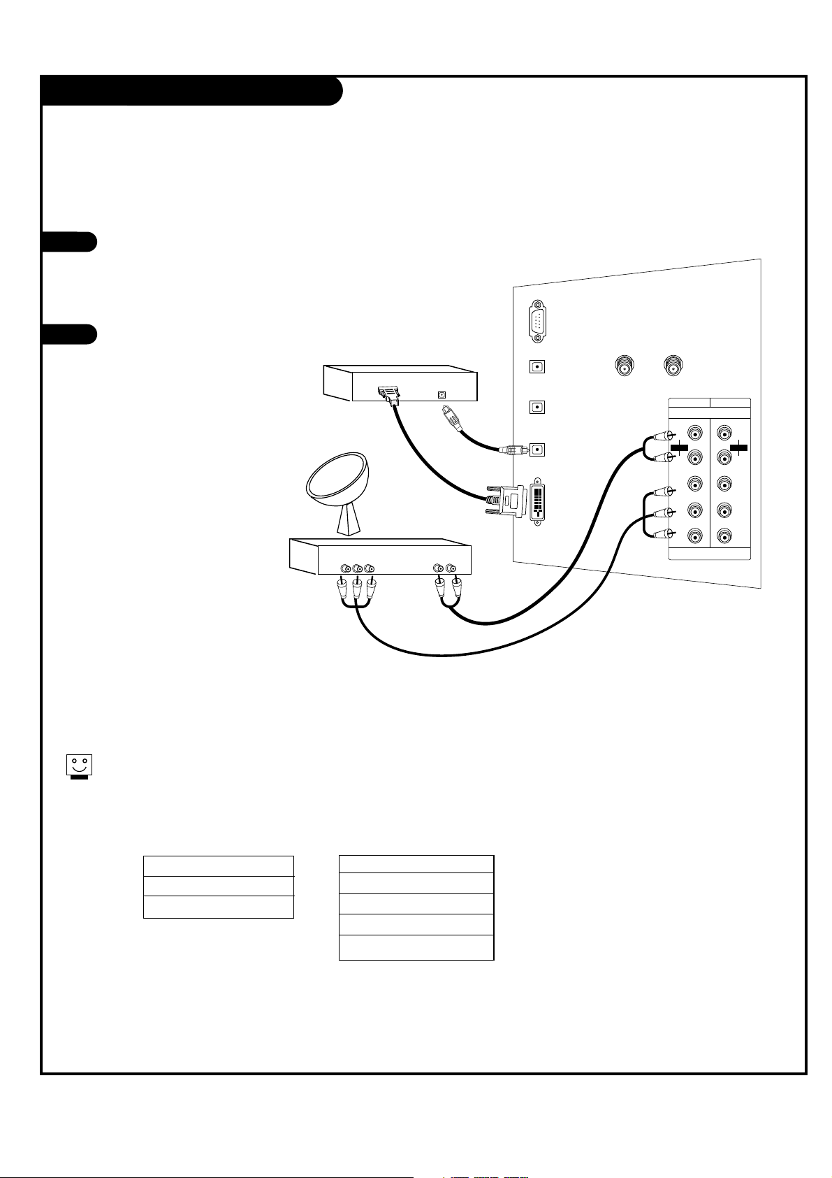
Set-top box Hookup
Find the audio and Y, PB, PR jacks or DVI
output port on the back of your set-top
box and connect them following the
instructions provided with your equipment.
Connect these cables to your TV as
shown.
1
2
Digital Audio
Optical Output
Audio
L R
Component Out
Y Pb Pr
CALIBRATION
DIGITAL
AUDIO OUTPUT
OPTICAL
ANTENNA 1 ANTENNA 2
DVI-HDTV INPUT
DIGITAL
AUDIO INPUT1
OPTICAL
(COMPONENT1)
DIGITAL
AUDIO INPUT2
OPTICAL
(DVI)
DVD/DTV INPUT
P
R
COMPONENT1
(480i/480p/720p/1080i)
COMPONENT2
PB
Y
L
R
AUDIO
P
R
PB
Y
L
R
AUDIO
+75 Ω +75 Ω
Set-top Box
Set-top Box
Th
e
1920x1080i
1280x720p
720x480p
DVI
or
Component 1 (or 2) Input
Y PB PR
1920X1080i
1280X720p
720X480p
720X480i
Page 14

PAGE 14
206-03890
Monitor Out Setup
Your TV has a special signal output capability which allows you to hook up a second TV or monitor.
Just connect the second TV or monitor to
the Monitor output Audio/Video jacks
located on the back of your TV. See the
Operating Manual of the second TV or
monitor for further details regarding that
device’s input settings.
1
2
Audio
input
Video
input
S-Video
VIDEO
VIDEO
AUDIO
L(MONO) R
S-VIDEO VIDEO/AUDIO INPUT MONITOR OUTPUT
VARIABLE
AUDIO
IN1
IN2
IN3
R
L
R
L
AUDIO
R
L
AUDIO
A/V cables
not included
with TV
Second TV
D
TV
Page 15

PAGE 15
206-03890
External Stereo
Locate the Variable Audio Out jacks on the
back of your TV and the Input jacks on
the back of your stereo's amplifier.
Connect the two jacks, making sure that
the right and left channels are connected
correctly.
Set up your speakers through your analog
stereo amplifier, according to the instructions provided with the amplifier.
1
2
3
VIDEO
VIDEO
AUDIO
L(MONO) R
S-VIDEO VIDEO/AUDIO INPUT MONITOR OUTPUT
VARIABLE
AUDIO
IN1
IN2
IN3
R
L
AUDIO
R
L
AUDIO
A/V cables
not included
with TV
Analog stereo amplifier
Hook
up
Variabl
Page 16

PAGE 16
206-03890
Digital Audio Output
Connect one end of an optical cable to
the TV Digital Audio Optical Output port.
Connect the other end of the optical cable
to the digital audio optical input on the
audio equipment.
See the external audio equipment instruction manual for operation.
1
2
Digital Audio
Optical Input
CALIBRATION
DIGITAL
AUDIO OUTPUT
OPTICAL
ANTENNA 1 ANTENNA 2
DVI-HDTV INPUT
DIGITAL
AUDIO INPUT1
OPTICAL
(COMPONENT1)
DIGITAL
AUDIO INPUT2
OPTICAL
(DVI)
+75 Ω + 75 Ω
Send the TV’s audio out to external audio equipment (stereo system) via
the Digital Audio Output Optical port.
Caution:
Do
not
loo
k
into
Digital Audio
Equipment
Page 17
PAGE 17
206-03890
Turning the TV On
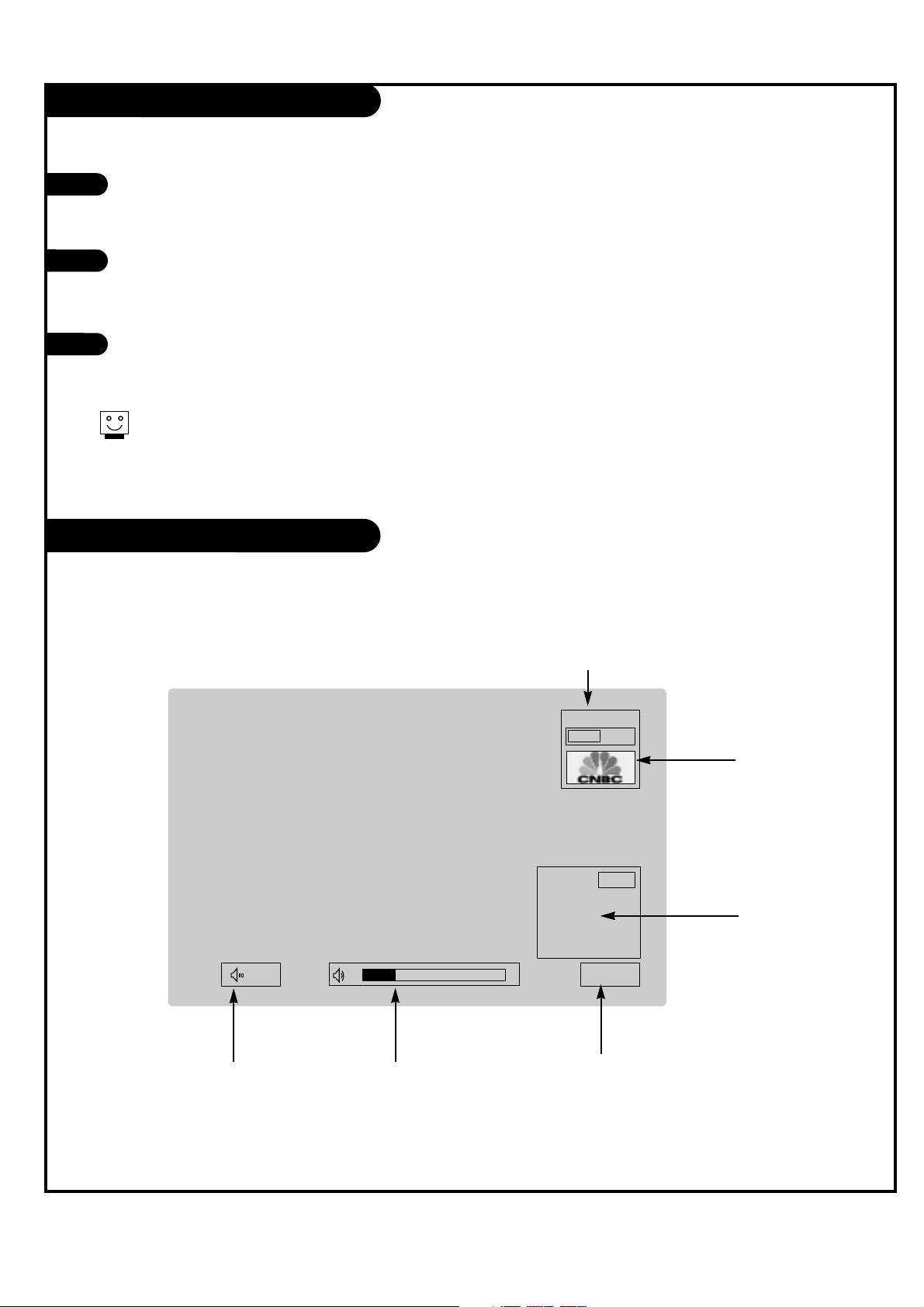
On-Screen Displays
This page describes your on-screen display and information banner options.
10
Mute
TV 2-0
MONO
10:00 AM
TV 12-0
First, connect antenna cable and power cord correctly. At this moment, the TV switches to standby mode.
In standby mode to turn TV on, press the POWER, CH UP/DOWN, TV/VIDEO, FRONT, COMP/DVI or number buttons on the remote control or POWER, TV/VIDEO or CH UP/DOWN on the TV.
Select the viewing source by using TV/VIDEO, COMP/DVI or FRONT buttonon the remote control.
This TV is programmed to remember which mode it was last set to, even if you turn the TV off.
Note: See page 20 if you have not auto programmed the TV to receive channels in your local broadcast area.
When finished using the TV, press the POWER button on the remote control. The TV reverts to standby mode.
1
2
3
If
PIP Display
This display
appears when PIP
is active.
Volume
Volume level is displayed
while adjusting the sound.
Mute
Appears when
sound is muted.
Time
Appears when pressing the
enter button on remote control.
Main Channel Display
Displays current channel number.
Main Channel
Label
Displays current
channel label.
Page 18
PAGE 18
206-03890
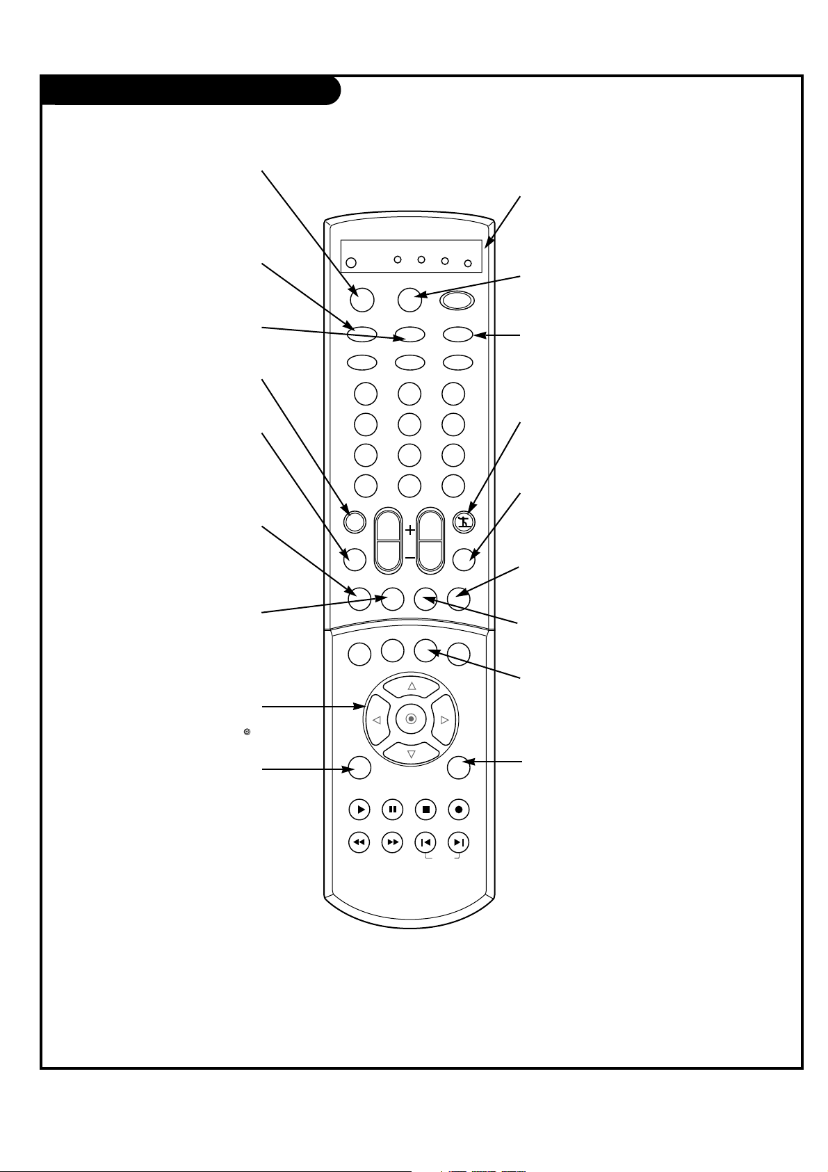
Remote Control Functions in TV Mode
1 2 3
4 5 6
7 8 9
0
tv
mode
light
power
tv/video
comp/dvi
freeze
vcr
cable
dvd
sat
mute
pip inputpipch- pipch+
pip
info
recordstop
pause
rew
play
ff
menu exit
timer cc
swap
vol
ch
surf
audio
video
signalratio
front
skip
dash(-) flashbk
SURF
Use to scroll the Surf channel
list.
MENU
Brings up the main menu
to the screen.
EXIT
Clears all on-screen displays
and returns to TV viewing
from any menu.
CC
Lets you select a closed caption
mode for displaying captioning
information when provided for
DTV/Analog signal.
VIDEO
Adjusts the factory preset picture according to the room.
PIPCH+
Changes to next higher PIP
channel.
PIP INPUT
Selects the input source for
the sub picture.
MUTE
Switches the sound on or off
THUMBSTICK
Allows you to navigate the on-screen
menus and to adjust the system set-
tings and preferences, by moving to
an option with
F G
and selecting the
highlighted option with .
TV/VIDEO
Selects: DTV, Analog, Video1,
Video2, Video3, Front video,
Component 1-2, and DVI input
sources.
MODE
Selects the remote operating mode:
TV, VCR, Cable, DVD or Satellite.
Select other operating modes, for
the remote to operate external
devices.
FRONT
Selects the front video input
sources.
COMP/DVI
Selects: Component 1,
Component 2, and DVI input
sources.
AUDIO
Selects MTS sound: Mono,
Stereo, and SAP.
Change the audio language
in DTV mode.
PIPCH-
Changes to next lower
PIP channel
PIP
Switches between PIP, POP
(Picture-out-of-Picture) and
Twin picture mode.
LIGHT
Illuminates the remote control
buttons.
MODE INDICATOR
LIGHTS
Show active remote mode
every time any button is
pressed.
D
E
Page 19

PAGE 19
206-03890
Remote Control Functions in TV Mode
1 2 3
4 5 6
7 8 9
0
tv
mode
light
power
tv/video
comp/dvi
freeze
vcr
cable
dvd
sat
mute
pip inputpipch- pipch+
pip
info
recordstop
pause
rew
play
ff
menu exit
timer cc
swap
vol
ch
surf
audio
video
signalratio
front
skip
dash(-) flashbk
POWER
Turns your TV or any other
programmed equipment on or
off, depending on mode.
CHANNEL UP/DOWN
Scrolls through available channels
present in EZ Scan memory.
NUMBER KEYPAD
For direct channel selection and
programming functions.
ENTER
When in the menu system and
other on-screen displays,
selects highlighted options.
RECORD, PAUSE, REW, FFWD,
PLAY, STOP
Control the functions on your VCR.
VOLUME UP/DOWN
Increases/decreases the sound level.
INFO
When you watch the TV, dis-
plays information on top of the
screen. Not available in
Component 1-2 and DVI.
SKIP LEFT/RIGHT
Playing CDs: Selects songs.
Playing DVDs: Selects movie
chapters.
RATIO
Changes the aspect ratio.
SIGNAL
Displays the digital signal strength.
DASH
Is used to enter a program num-
ber for multiple program channels
such as 2—1,2—2,etc.
FLASHBK
Tunes to the last channel
viewed.
TIMER
Lets you select the amount of
time before your TV turns
itself off automatically.
SWAP
Swaps the signal from your PIP
window to the main screen.
FREEZE
Captures and freezes the
currently-viewed picture.
Main picture is frozen in
PIP or Twin picture mode.
Page 20

PAGE 20
206-03890
EZ Scan (Channel Search)
Use pages 9-13 to connect external
equipment to your TV. If you have not
done so, plug in your TV to a standard
120V, 60Hz power outlet.
If you have not done so, remove the back
of the remote and put in two AA batteries. Make sure batteries are properly
installed (check the +/– symbols).
With the remote control in hand, press
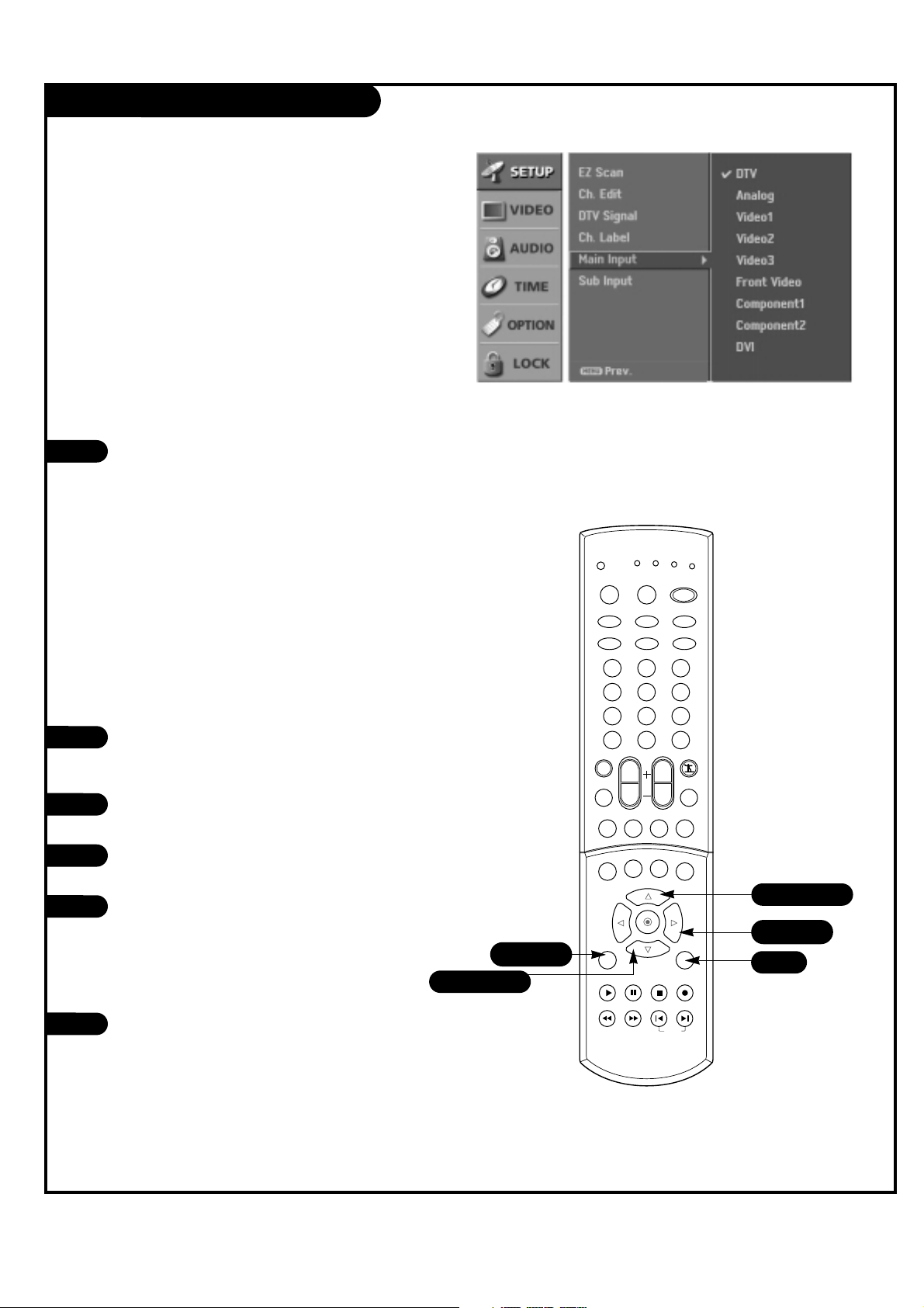
the POWER button to turn your TV on.
1
2
3
Automat
ically
f
inds
all
back of
remote
1 2 3
4 5 6
7 8 9
0
tv
mode
light
power
tv/video
comp/dvi
freeze
vcr
cable
dvd
sat
mute
pip inputpipch- pipch+
pip
info
recordstop
pause
rew
play
ff
menu exit
timer cc
swap
vol
ch
surf
audio
video
signalratio
front
skip
dash(-) flashbk
4
8
3
OO
OO
4/6/7
4/6/7
5/6
Page 21
PAGE 21
206-03890
EZ Scan continued
Press the MENU button on the remote control, then
use the UP/DOWN arrow button to select the Setup
menu
Press the RIGHT arrow button to access the Setup
menu.
Use the UP/DOWN arrow button to select EZ Scan,
then press the RIGHT arrow button.
Use the UP/DOWN arrow button to select option 1,
2, 3, or 4. (Based on your connection(s) to
Antenna 1-2.)
Press ENTER button to begin the channel search.
Note: Allow EZ Scan to complete the channel
search cycle for TV, CABLE*, DTV, etc.
4
5
6
7
8
Run
EZ
Mini glossary
TV The antenna device receiving the program signal sent over-the-air.
DTV Digital TV programming sent over-the-air.
CATV Your EZ Scan selection, if you subscribe to a cable service.
CADTV Your EZ Scan selection, if you subscribe to a digital cable service.
*Cable Service Band Note: Select Std=Standard, HRC=HRC Band, or IRC=IRC Band.
For further band information, contact your cable service provider.
Page 22

PAGE 22
206-03890
Channel Edit
Creat
e two
di
f
f
er
ent
types
of
channel
lists
in
Press the MENU button on the remote
control, then use the UP/DOWN arrow
button to select the Setup menu.
Press the RIGHT arrow button to access
the Setup menu.
Use the UP/DOWN arrow button to select
CH.Edit and then press the RIGHT arrow
button.
You will now see a screen filled with
channel numbers and a preview picture.
Use the UP/DOWN and LEFT/RIGHT arrow
button to select a channel, then use
the button to add or delete it. Press
SURF to add the channel to the Surf List.
Press EXIT button to return to TV viewing
or press MENU button to return to the
previous menu.
3
4
5
2
1
1/5
4
5
4
2/3/4
1/3/4
1/3/4
4
CA
TV
is
availabl
vcr
tv
mode
tv/video
mute
audio
cable
light
front
signalratio
1 2 3
4 5 6
7 8 9
dash(-) flashbk
0
vol
ch
pip
dvd
power
comp/dvi
freeze
surf
video
pip inputpipch- pipch+
sat
timer cc
info
menu exit
play
pause
rew
swap
recordstop
ff
skip
Page 23

PAGE 23
206-03890
DTV Signal
1
2
Press the SIGNAL button on the remote
control.
View the on-screen signal strength monitor to see the quality of the signal being
received.
Press EXIT button to return to TV viewing.
3
L
ets
you
know
NO
T
all
areas
Using the SIGNAL button
1
2
Press the MENU button on the remote
control, then use the UP/DOWN arrow
button to select the Setup menu.
Press the RIGHT arrow button to access
the Setup menu.
Use the UP/DOWN arrows to select the
DTV Signal. Current signal strength is
shown on menu.
Press EXIT button to return to TV viewing.
3
4
Using the menu
1 2 3
4 5 6
7 8 9
0
tv
mode
light
power
tv/video
comp/dvi
freeze
vcr
cable
dvd
sat
mute
pip inputpipch- pipch+
pip
info
recordstop
pause
rew
play
ff
menu exit
timer cc
swap
vol
ch
surf
audio
video
signalratio
front
skip
dash(-) flashbk
1/3
1/3
4
2
1
Page 24

PAGE 24
206-03890
Channel Label Setup
Choose
pr
es
et
labels
for
Press the MENU button on the remote
control, then use the UP/DOWN arrow
button to select the Setup menu.
Press the RIGHT arrow button to access
the Setup menu.
Use the UP/DOWN arrow button to select
CH.Label and then press the RIGHT arrow
button.
You will now see a screen filled with
Labels and a preview screen. Use channel
UP/DOWN button on your remote control
to select the a channel to Label.
Use the UP/DOWN and LEFT/RIGHT arrows
to select the appropriate label for the
channel and press to set the Label to
the selected channel.
Repeat 4 and 5 steps until all channels
are Labeled.
Press EXIT button to return to TV viewing
or press MENU button to return to the
previous menu.
3
4
5
6
7
2
1
1 2 3
4 5 6
7 8 9
0
tv
mode
light
power
tv/video
comp/dvi
freeze
vcr
cable
dvd
sat
mute
pip inputpipch- pipch+
pip
info
recordstop
pause
rew
play
ff
menu exit
timer cc
swap
vol
ch
surf
audio
video
signalratio
front
skip
dash(-) flashbk
1/7
5
7
4
2/3/5
1/3/5
1/3/5
5
Th
e
TV
dis
Page 25
PAGE 25
206-03890
Main Picture Source Selection
1
2
Press the MENU button on the remote
control, then use the UP/DOWN arrow
button to select the Setup menu.
Press the RIGHT arrow button to access
the Setup menu.
Use the UP/DOWN arrows to select the
Main Input option.
Press the RIGHT arrow to access the Main
Input menu, then use the UP/DOWN arrow
button to select the source. Your Main
picture source options are : DTV, Analog,
Video 1, Video 2, Video 3, Front video,
Component 1, Component 2, and DVI.
Press EXIT button to return to TV viewing
or press MENU button to return to the
previous menu.
3
4
5
Note:
Th
is
TV
is
equ
ip
p
ed
with
P
ictur
1 2 3
4 5 6
7 8 9
0
tv
mode
light
power
tv/video
comp/dvi
freeze
vcr
cable
dvd
sat
mute
pip inputpipch- pipch+
pip
info
recordstop
pause
rew
play
ff
menu exit
timer cc
swap
vol
ch
surf
audio
video
signalratio
front
skip
dash(-) flashbk
1/5
2/4
5
1/3/4
1/3/4
Using the menu
1
Use the TV/VIDEO, FRONT, and COMP/DVI
button to select the input source.
Each time you press TV/VIDEO button, you
toggle between DTV, Analog, Video 1, Video
2, Video 3, Front Video, Component 1,
Component 2, and DVI.
Each time you press FRONT button, you
toggle between connected Front Video
sources.
Each time you press COMP/DVI button, you
toggle between Component 1, Component
2, and DVI.
Using the TV/VIDEO, FRONT, and COMP/DVI button
Page 26
PAGE 26
206-03890
PIP (Picture-In-Picture) Options
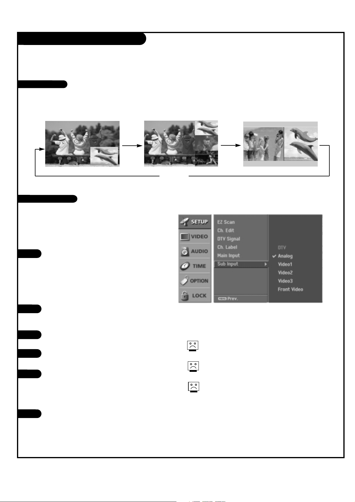
Press the MENU button on the remote
control, then use the UP/DOWN arrow
button to select the Setup menu.
Press the RIGHT arrow button to access
the Setup menu.
Use the UP/DOWN arrows to select the
Sub Input option.
Press the RIGHT arrow to access the Sub
Input menu, then use the UP/DOWN arrow
button to select the source. Your choices
are: DTV, Analog, Video 1, Video 2, Video
3, and Front Video.
Press EXIT button to return to TV viewing
or press MENU button to return to the
previous menu.
1
1
2
3
4
5
Changes
the
pi
Press the PIP button to show the sub picture.
Each press of PIP changes the PIP options as shown below.
PIP
lets you
view 2
dif-
Use the PIP INPUT button to select the
input source for the sub picture.
Each time you press PIP INPUT button,
you toggle between DTV, Analog, Video 1,
Video 2, Video 3, and Front Video.
Do
not
dis
play a
f
ix
ed
imag
You
can’t
Using the menu
Using the PIP INPUT button
PIP mode POP mode
PIP off
Twin Picture mode
Watching PIP
PIP Source Selection
Page 27

PAGE 27
206-03890
PIP (Picture-In-Picture) Options
1
2
Press the SWAP button.
Each time you press the SWAP button, you switch the Main and PIP pictures.
Press the PIP button.
Select the Analog or DTV option on the Sub input menu or with the PIP INPUT button. Use
the PIPCH-/PIPCH+ button to select a channel for the sub picture.
Main Picture Sub Picture
Selecting PIP Channels
Swapping Screen
In the PIP mode, each press of the UP/DOWN/LEFT/RIGHT arrow button will
move the sub picture to a different position on the screen.
Moving the Sub Picture
Page 28
PAGE 28
206-03890
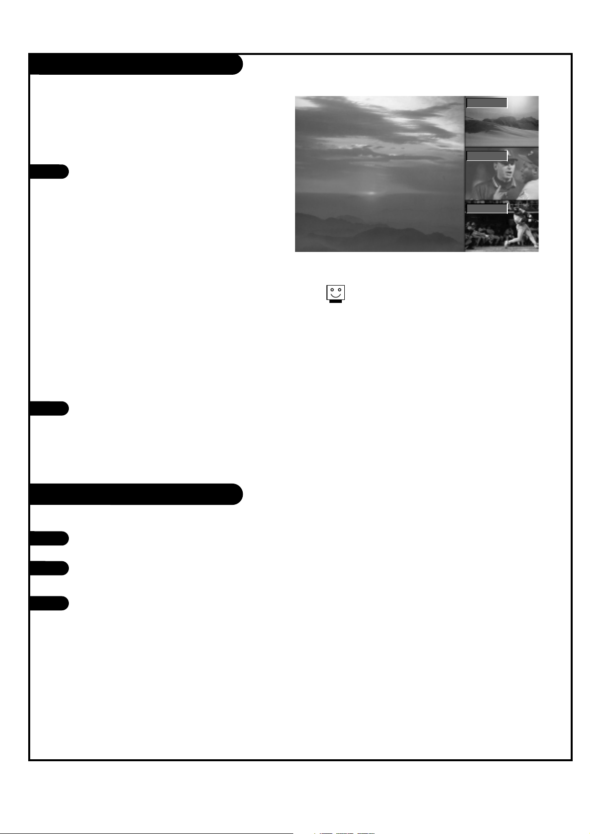
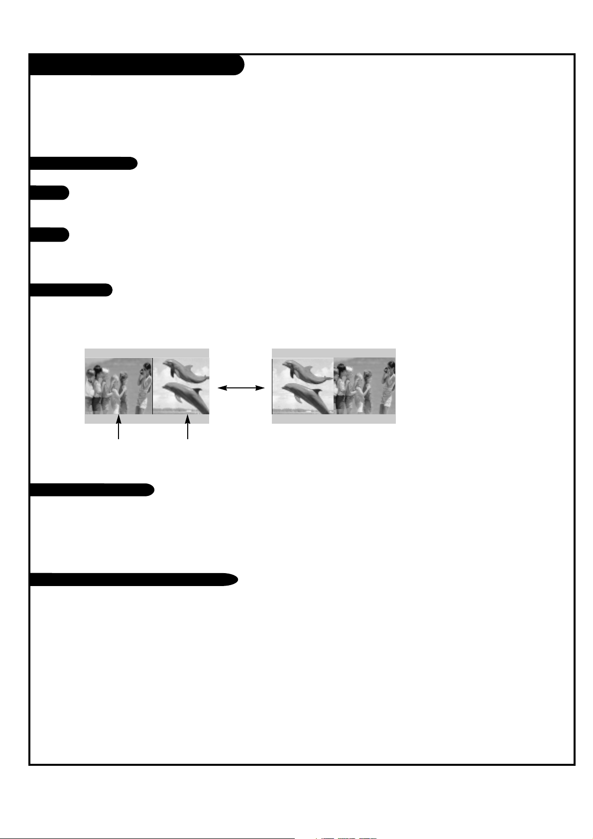
Press PIP on the remote control with the
PIP image on the screen to activate POP
(Picture-out-of-Picture) mode.
The pictures of all the programmed channels are searched with the 3 PIP screen, as
shown to the right.
• Channel selection: Press LEFT arrow button to enlarge the selected channel
being searched on the PIP screen to
view it on the Main screen.
• PIP selection: Use UP/DOWN arrow button to select one of 3 PIP screen pictures in POP mode.
• Input source selection for PIP: Use PIP
INPUT button or Sub input of Setup
menu to select input souce for sub picture (You can’t select DTV for main and
sub picture simultaneously).
Press the EXIT button to exit POP mode.
1
In DTV 720p/1080i mode, press the FREEZE
button.
Use UP/DOWN/LEFT/RIGHT arrow button to
select the screen split zoom section.
Press the FREEZE/RATIO button to return to
TV viewing or press the EXIT button to
return to a frozen picture again.
1
2
3
2
Us
e
PO
Run
EZ
Sc
F TV 13-0
EE
DD
TV 51-0
TV 63-0
Multi Point Zooming
POP (Picture-Out-Of-Picture) Source
Page 29
PAGE 29
206-03890
Twin Picture
Twin
Pictur
Use the PIP INPUT button to select the input source for the sub picture.
Each time you press PIP INPUT, you toggle between DTV, Analog, Video 1,
Video 2, Video 3, and Front Video.
1
2
Press the Swap button.
Each time you press SWAP, you switch the PIP and Main screen channels.
Press the PIP button on the remote control in POP mode to activate twin picture mode.
Select the Analog or DTV option on the Sub input menu or with the PIP INPUT button.
Use the PIPCH-/PIPCH+ button to select a channel for the sub picture.
Press the EXIT button to exit twin picture mode.
Main Picture Sub Picture
Watching Twin Picture
Swapping Screen
Selecting an Input Signal Source for Sub Picture
Use the UP/DOWN/LEFT/RIGHT arrow button to adjust main and sub picture
size in twin Picture mode.
Adjusting Sub Picture Size
Page 30
PAGE 30
206-03890
VIDEO Menu
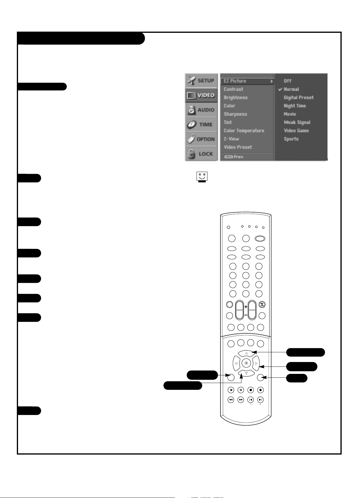
Use the VIDEO button to select EZ Picture option.
Each press of the VIDEO button change the EZ
Picture option: Off, Normal, Digital Preset, Night
Time, Movie, Weak Signal, Video Game, and
Sports.
Press EXIT to save and return to TV viewing.
1
2
Th
is
funct
ion adjusts
the
TV to
the
best
pictur
EZ Picture
Choos
e
the
Using the VIDEO button
1
2
Press the MENU button on the remote control,
then use the UP/DOWN arrow button to select
the Video menu.
Press the RIGHT arrow button to access the Video
menu.
Use the UP/DOWN arrows to select the EZ Picture
option.
Press the RIGHT arrow to access the EZ Picture
menu, then use the UP/DOWN arrow button to
select the options: Off, Normal, Digital Preset,
Night Time, Movie, Weak Signal, Video Game, and
Sports.
• Off: Allows you to adjust the picture the way
you want.
• Normal: Resets all the options to their preset
values.
• Other options adjust the picture to the source’s
image.
Press EXIT button to return to TV viewing or press
MENU button to return to the previous menu.
3
4
5
Using the menu
1 2 3
4 5 6
7 8 9
0
tv
mode
light
power
tv/video
comp/dvi
freeze
vcr
cable
dvd
sat
mute
pip inputpipch- pipch+
pip
info
recordstop
pause
rew
play
ff
menu exit
timer cc
swap
vol
ch
surf
audio
video
signalratio
front
skip
dash(-) flashbk
1/5
2/4
5
1/3/4
1/3/4
Each
vid
eo
Page 31
PAGE 31
206-03890
VIDEO Menu
Press the MENU button on the remote
control, then use the UP/DOWN arrow
button to select the Video menu.
Press the RIGHT arrow button to access
the Video menu.
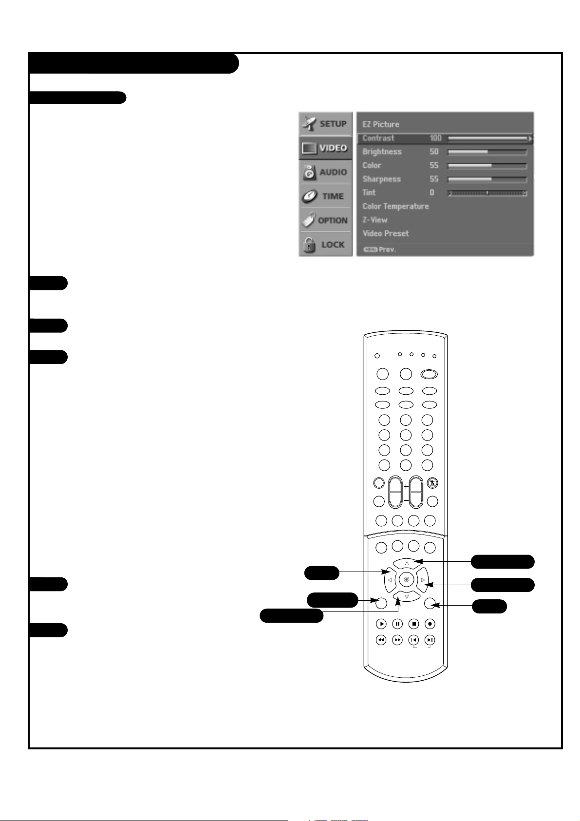
Use the UP/DOWN arrow button to select
one of the following options: Contrast,
Brightness, Color, Sharpness, or Tint, then
press the RIGHT arrow button.
• Contrast: Adjusts the difference
between the light and dark levels of
the picture.
• Brightness: Adjusts the white or light
level of the overall picture.
• Color: Adjusts the intensity of all col-
ors.
• Sharpness: Adjusts the level of crisp-
ness in the edges between the light
and dark areas of the picture. The lower
the level, the softer the image.
• Tint: Adjusts the balance between the
red and green levels.
Use the LEFT/RIGHT arrow button to
adjust the option to your preference. Use
the UP/DOWN arrow button to select
another option.
Press EXIT button to return to TV viewing
or press MENU button to return to the
previous menu.
1
2
3
You can
manually adjust
Adjust
the
pictur
4
5
1 2 3
4 5 6
7 8 9
0
tv
mode
light
power
tv/video
comp/dvi
freeze
vcr
cable
dvd
sat
mute
pip inputpipch- pipch+
pip
info
recordstop
pause
rew
play
ff
menu exit
timer cc
swap
vol
ch
surf
audio
video
signalratio
front
skip
dash(-) flashbk
1/5
4
5
2/3/4
1/3/4
1/3/4
Manual Video Control
Page 32

PAGE 32
206-03890
VIDEO Menu
Press the MENU button on the remote control, then use
the UP/DOWN arrow button to select the Video menu.
Press the RIGHT arrow button to access the Video
menu.
Use the UP/DOWN arrow button to select Video Preset.
Use the RIGHT arrow button to preset the video configuration.
1
2
3
Th
is
is
the
4
Video Preset
Press the MENU button on the remote control, then use
the UP/DOWN arrow button to select the Video menu.
Press the RIGHT arrow button to access the Video
menu.
Use the UP/DOWN arrow button to select Z-View, and
then press the RIGHT arrow button.
Use the UP/DOWN arrow button to select Off or On.
On, automatically adjusts the picture display for optimum quality.
Press EXIT button to return to TV viewing or press
MENU button to return to the previous menu.
1
2
3
4
5
Z-View
Press the MENU button on the remote control, then use
the UP/DOWN arrow button to select the Video menu.
Press the RIGHT arrow button to access the Video
menu.
Use the UP/DOWN arrow button to select Color
Temperature, and then press the RIGHT arrow button.
Use the UP/DOWN arrow button to select Warm,
Medium, or Cool.
Press EXIT button to return to TV viewing or press
MENU button to return to the previous menu.
1
2
3
Lets you
choose one
of
4
5
Color Temperature
Page 33

PAGE 33
206-03890
AUDIO Menu
Press the MENU button on the remote
control, then use the UP/DOWN arrow
button to select the Audio menu.
Press the RIGHT arrow button to access
the Audio menu.
Use the UP/DOWN arrow button to select
Audio Language, then press the RIGHT
arrow button.
Use the UP/DOWN arrow button to select
the language you wish.
Press EXIT button to return to TV viewing
or press MENU button to return to the
previous menu.
1
2
3
Other languages may
be available
4
5
Audio Language
Press the MENU button on the remote
control, then use the UP/DOWN arrow
button to select the Audio menu.
Press the RIGHT arrow button to access
the Audio menu.
Use the UP/DOWN arrow button to select
EZ SoundRite, then press the RIGHT arrow
button.
Use the UP/DOWN arrow button to select
On or Off.
Press EXIT button to return to TV viewing
or press MENU button to return to the
previous menu.
1
2
3
Scans for
changes in sound
4
5
EZ SoundRite
Page 34

PAGE 34
206-03890
AUDIO Menu
1
2
Th
is
funct
ion
lets you
enjoy
the
This
TV can
Use the AUDIO button to select your desired MTS mode. Each time you press the
AUDIO button, MONO, STEREO, or SAP appear in turn.
Press EXIT to save and return to TV viewing.
EZ Sound
Stereo/SAP Broadcasts Setup
Choos
e
the
Ster
eo or
SAP
Mono sound is
automatically
rece
Sel
ect MONO
if
1
2
Press the MENU button on the remote
control, then use the UP/DOWN arrow
button to select the Audio menu.
Press the RIGHT arrow button to access
the Audio menu.
Use the UP/DOWN arrows to select the EZ
Sound option.
Press the RIGHT arrow to access the EZ
Sound menu, then use the UP/DOWN
arrow button to select the options: Off,
Normal, Stadium, News, Music and
Theater.
• Off: Allows you to adjust the picture
the way you want.
• Normal: Resets all the options to their
preset values.
• Other options adjust the TV's audio output to the source’s sound.
Press EXIT button to return to TV viewing
or press MENU button to return to the
previous menu.
3
4
5
Page 35

PAGE 35
206-03890
AUDIO Menu
Press the MENU button on the remote control, then use
the UP/DOWN arrow button to select the Audio menu.
Press the RIGHT arrow button to access the Audio
menu.
Use the UP/DOWN arrow button to select one of the
following options: Balance, Treble, or Bass, then press
the Right arrow button.
• Bass: Increases or decreases the lower frequency
sounds from the TV speakers.
• Treble: Increases or decreases the higher frequency
sounds from the TV speakers.
• Balance: Lets you adjust the left to right balance of
the TV speakers.
Use the LEFT/RIGHT arrow button to adjust the option
to your preference. Use the UP/DOWN arrows to select
another option.
Press EXIT button to return to TV viewing or press
MENU button to return to the previous menu.
1
2
3
Adjust the
Turns
4
5
Manual Sound Control
Turn TV Speakers On/Off
1
2
Press the MENU button on the remote control, then use
the UP/DOWN arrow button to select the Audio menu.
Press the RIGHT arrow button to access the Audio
menu.
Use the UP/DOWN arrow button to select TV Speaker,
then press the RIGHT arrow button.
Use the UP/DOWN arrow button to select On or Off.
Press EXIT button to return to TV viewing or press
MENU button to return to the previous menu.
3
4
5
Page 36

PAGE 36
206-03890
AUDIO Menu
Front Surround
1
2
Press the MENU button on the remote
control, then use the UP/DOWN arrow
button to select the Audio menu.
Press the RIGHT arrow button to access
the Audio menu.
Use the UP/DOWN arrow button to select
Front Surround, then press the RIGHT
arrow button.
Use the UP/DOWN arrow button to select
Off, 3D EchoSound System or SRS (Sound
Retrieval System) TruSurround XT.
Press EXIT button to return to TV viewing
or press MENU button to return to the
previous menu.
3
4
5
is a
trademar
k
1 2 3
4 5 6
7 8 9
0
tv
mode
light
power
tv/video
comp/dvi
freeze
vcr
cable
dvd
sat
mute
pip inputpipch- pipch+
pip
info
recordstop
pause
rew
play
ff
menu exit
timer cc
swap
vol
ch
surf
audio
video
signalratio
front
skip
dash(-) flashbk
1/5
2/3
5
1/3/4
1/3/4
Manufactur
ed
under
Mini glossary
SRS TruSurround XT
Takes advantage of any multi-channel format
without needing to add extra speakers or equipment. Dialog clarity, bass enrichment and the
addition of stereo audio enhancement that produces an immersive sound experience from standard stereo material.
3D EchoSound System
Creates a stunning simulated stereo effects from
any mono sound and a realistic three-dimensional
sound with a very wide and deep sound stage
into stereo sound.
Page 37

PAGE 37
206-03890
Auto Clock Setup
Press the MENU button on the remote
control, then use the UP/DOWN arrow
button to select the Time menu option.
Press the RIGHT arrow button to go to
the Time menu.
Use the UP/DOWN arrow button to choose
Auto Clock, then press the RIGHT arrow
button.
Use the UP/DOWN arrow button to choose
On, then use the RIGHT arrow button to
select Time Zone.
Use the UP/DOWN arrow button to adjust
Time Zone.
• Select the time zone for your viewing
area. Your options are: Eastern,
Central, Mountain, Pacific, Alaska,
Hawaii.
Press EXIT button to return to TV viewing
or press MENU button to return to the
previous menu.
1
2
3
4
5
6
S
ets
the
tim
e
automatically
through
1 2 3
4 5 6
7 8 9
0
tv
mode
light
power
tv/video
comp/dvi
freeze
vcr
cable
dvd
sat
mute
pip inputpipch- pipch+
pip
info
recordstop
pause
rew
play
ff
menu exit
timer cc
swap
vol
ch
surf
audio
video
signalratio
front
skip
dash(-) flashbk
1/6
6
2/3/4
1/3/4/5
1/3/4/5
Page 38

PAGE 38
206-03890
Manual Clock Setup
Press the MENU button on the remote
control, then use the UP/DOWN arrow
button to select the Time menu option.
Press the RIGHT arrow button to activate
the Time menu.
Use the UP/DOWN arrow button to choose
Manual Clock, then press the RIGHT arrow
button.
Use the LEFT/RIGHT arrow button to
select either the year, hour or minutes
option. Once selected, use the UP/DOWN
arrow button to set the year, hours or
minutes.
Press EXIT button to return to TV viewing
or press MENU button to return to the
previous menu.
1
2
3
4
5
I
f
current
tim
1 2 3
4 5 6
7 8 9
0
tv
mode
light
power
tv/video
comp/dvi
freeze
vcr
cable
dvd
sat
mute
pip inputpipch- pipch+
pip
info
recordstop
pause
rew
play
ff
menu exit
timer cc
swap
vol
ch
surf
audio
video
signalratio
front
skip
dash(-) flashbk
1/5
5
2/3/4
1/3/4
1/3/4
4
Page 39

PAGE 39
206-03890
TV Turn Off Time Setup
Press the MENU button on the remote
control, then use the UP/DOWN arrow
button to select the Time menu.
Press the RIGHT arrow button to to go to
the Time menu.
Use the UP/DOWN arrow button to choose
Off Timer, then press the RIGHT.
Use the UP/DOWN arrow button to choose
On, then press the RIGHT arrow button.
Use the LEFT/RIGHT arrow button to
select the hour or minutes options, then
use the UP/DOWN arrow button to set the
hours or minutes.
Press EXIT button to return to TV viewing
or press MENU button to return to the
previous menu.
1
2
3
4
5
L
ets you
set an
automatic
daily turn
of
f
tim
6
Next G
1 2 3
4 5 6
7 8 9
0
tv
mode
light
power
tv/video
comp/dvi
freeze
vcr
cable
dvd
sat
mute
pip inputpipch- pipch+
pip
info
recordstop
pause
rew
play
ff
menu exit
timer cc
swap
vol
ch
surf
audio
video
signalratio
front
skip
dash(-) flashbk
1/6
5
6
1/3/4/5
2/3/4/5
1/3/4/5
Page 40

PAGE 40
206-03890
TV Turn On Time Setup
L
ets you
set an
automatic
daily turn
on
tim
e
for
your
TV.
Of
Press the MENU button on the remote
control, then use the UP/DOWN arrow
button to select the Time menu.
Press the RIGHT arrow button to activate
the Time menu.
Use the UP/DOWN arrow button to choose
On Timer, then press the RIGHT arrow
button.
Use the UP/DOWN arrows to choose On,
then press the RIGHT arrow button.
Use the LEFT/RIGHT arrow button to
select either Time, Channel, or Volume.
Once selected, use the UP/DOWN arrow
button to set either the Time, Channel, or
Volume options.
Press EXIT button to return to TV viewing
or press MENU button to return to the
previous menu.
1
2
3
4
5
6
T
o
canc
el
On
T
1 2 3
4 5 6
7 8 9
0
tv
mode
light
power
tv/video
comp/dvi
freeze
vcr
cable
dvd
sat
mute
pip inputpipch- pipch+
pip
info
recordstop
pause
rew
play
ff
menu exit
timer cc
swap
vol
ch
surf
audio
video
signalratio
front
skip
dash(-) flashbk
1/6
5
6
1/3/4/5
2/3/4/5
1/3/4/5
Page 41

PAGE 41
206-03890
Press the MENU button on the remote
control, then use the UP/DOWN arrow
button to select the Time menu.
Press the RIGHT arrow button to go to
the Time menu.
Use the UP/DOWN arrow button to choose
Sleep Timer then press the RIGHT arrow
button.
Use the UP/DOWN arrows to choose a preset turn off time.
Press EXIT button to return to TV viewing
or press MENU button to return to the
previous menu.
1
2
3
4
5
Sleep Timer Setup
Press the TIMER button on the remote
control repeatedly to select the number of
minutes.
First the Off option will appear on the
screen, followed in sequence 10, 20, 30,
60, 90, 120, 180, and 240. The timer
begins to count down from the number of
minutes selected.
Press EXIT button to save and return to
TV viewing
1
2
L
ets you
sel
When
the
sle
T
o
T
o
chang
I
f
Using the TIMER button
Using the menu
1 2 3
4 5 6
7 8 9
0
tv
mode
light
power
tv/video
comp/dvi
freeze
vcr
cable
dvd
sat
mute
pip inputpipch- pipch+
pip
info
recordstop
pause
rew
play
ff
menu exit
timer cc
swap
vol
ch
surf
audio
video
signalratio
front
skip
dash(-) flashbk
1/5
2/3
5
1/3/4
1/3/4
Page 42

PAGE 42
206-03890
Auto Off
I
f
ther
e
is no
input
signal,
Press the MENU button on the remote
control, then use the UP/DOWN arrow
button to select the Time menu.
Press the RIGHT arrow button to go to
the Time menu.
Use the UP/DOWN arrow button to choose
Auto Off then press the RIGHT arrow.
Use the UP/DOWN arrows to choose On or
Off.
Press EXIT button to return to TV viewing
or press MENU button to return to the
previous menu.
1
2
3
4
5
1 2 3
4 5 6
7 8 9
0
tv
mode
light
power
tv/video
comp/dvi
freeze
vcr
cable
dvd
sat
mute
pip inputpipch- pipch+
pip
info
recordstop
pause
rew
play
ff
menu exit
timer cc
swap
vol
ch
surf
audio
video
signalratio
front
skip
dash(-) flashbk
1/5
2/3
5
1/3/4
1/3/4
Page 43

PAGE 43
206-03890
Aspect Ratio Control
Press the MENU button on the remote control, then use
the UP/DOWN arrow button to select the Option menu.
Press the RIGHT arrow button to go to the Option
menu.
Use the UP/DOWN arrows to choose the Aspect Ratio
option, then press the RIGHT arrow button.
Use the UP/DOWN arrow button to select the desired
picture format.
• Use the UP/DOWN arrow button to adjust the
enlarge proportion of Cinema Zoom. The adjustment
of range is 1~16.
Press EXIT button to return to TV viewing or press
MENU button to return to the previous menu.
1
2
3
4
5
Use the RATIO button to select the desired picture format.
Each press of the RATIO button changes the picture format. Your options are: Set By Program, 4:3, 16:9,
Horizon, Zoom1, Zoom2, and Cinema Zoom.
Press EXIT to save and return to TV viewing.
1
2
Lets you
choose the
way that an analog
picture
Using the RATIO button
Using the menu
Mini glossary
Set By Program Selects the proper picture proportion to match the source’s image. (4:3 → 4:3, 16:9 → 16:9)
4:3 Choose when you want to view a picture with an original 4:3 aspect ratio, with black bars appearing at both the left and right
sides.
16:9 Choose when you want to adjust the picture horizontally, in a linear proportion to fill the entire screen.
Horizon Choose when you want to adjust the picture in a non-linear proportion, that is, more enlarged at both sides, to create a spectacu-
lar view.
Zoom1 Choose when you want to view the picture without any alteration. However, the top and bottom portions of the picture will be
cropped.
Zoom2 Choose when you want the picture to be altered, both horizontally extended and vertically cropped. The picture taking a halfway
trade off between alteration and screen coverage.
Cinema Zoom Choose when you want to enlarge the picture in correct proportion. When enlarging or reducing the picture, the image may
become distorted.
When you
rec
e
iv
e a
pictur
e
Page 44

PAGE 44
206-03890
Closed Captions
1
2
1
2
3
4
5
Mini glossary
CAPTIONS The term for the words that scroll across the bot-
tom of the TV screen; usually the audio portion of
the program provided for the hearing impaired.
TEXT The term for the words that appear in a large
black frame and almost cover the entire screen;
usually messages provided by the broadcaster.
1/5
2/3
5
1/3/4
1/3/4
S
el
ect a
capti
on
mode
for
display
ing
capti
oning
in
Use the CC button to select caption.
Each press of the CC button changes the caption
option; Off, CC1, CC 2, CC 3, CC 4, Text 1, Text 2,
Text 3, or Text 4.
Press EXIT to save and return to TV viewing.
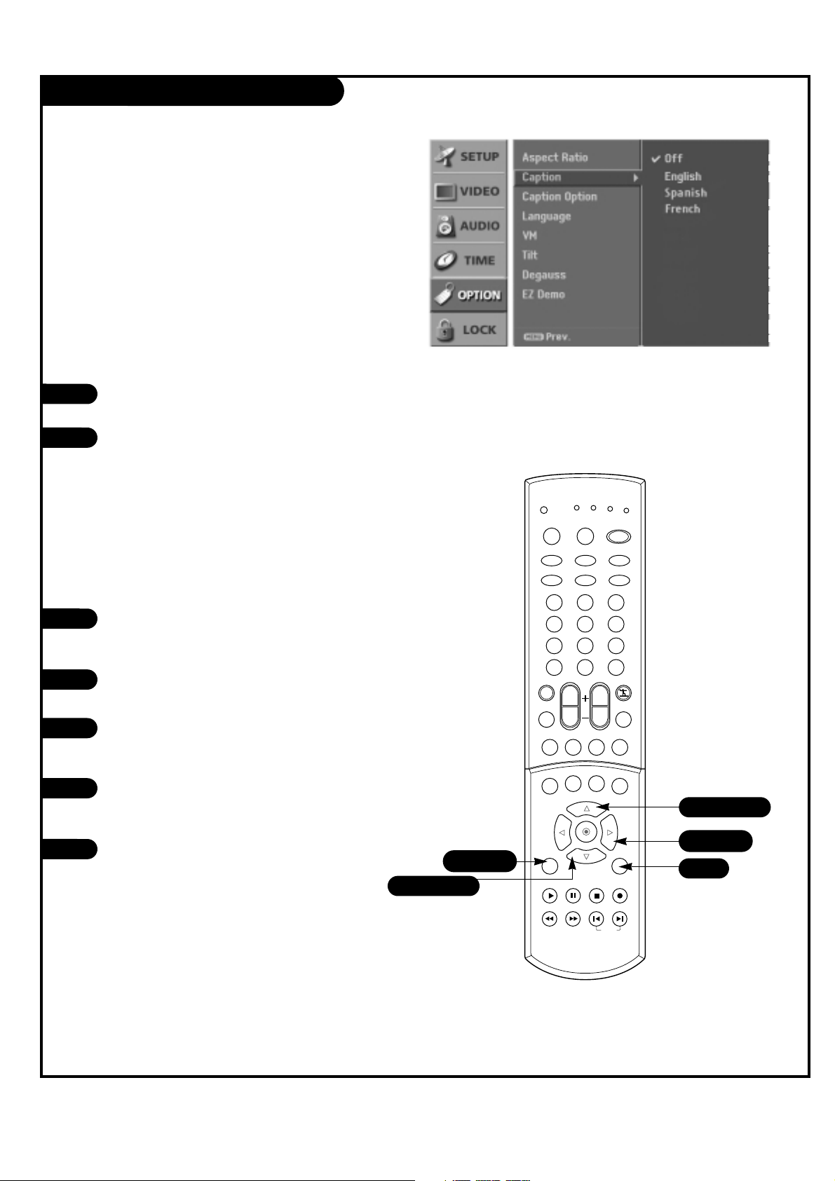
Press the MENU button on the remote control, then
use the UP/DOWN arrow button to select the Option
menu.
Press the RIGHT arrow button to activate the Option
menu.
Use the UP/DOWN arrow button to choose Caption,
then press the Right arrow button.
Use the UP/DOWN arrow button to make your caption
selection. Your choices are: Off, CC1, CC 2, CC 3, CC 4,
Text 1, Text 2, Text 3, or Text 4.
Press EXIT button to return to TV viewing or press
MENU button to return to the previous menu.
Using the CC button
Using the menu
Th
is
vcr
cable
light
front
signalratio
0
vol
timer cc
pause
ff
dvd
power
comp/dvi
ch
pip inputpipch- pipch+
recordstop
skip
tv
mode
tv/video
1 2 3
4 5 6
7 8 9
dash(-) flashbk
mute
audio
pip
info
menu exit
play
rew
sat
freeze
surf
video
swap
Page 45
PAGE 45
206-03890
Closed Captions (Continued)
1
2
Press the MENU button on the remote
control, then use the UP/DOWN arrow
button to select the Option menu.
Press the RIGHT arrow button to access
the Option menu.
Use the UP/DOWN arrows to select the
Caption, then press the RIGHT arrow button.
Use the UP/DOWN arrow button to choose
any of the following options : Off,
English, Spanish, or French.
Press EXIT button to return to TV viewing
or press MENU button to return to the
previous menu.
1
2
Press the CC button repeatedly to scroll
and select available caption languages.
Press EXIT to save and return to TV viewing.
3
4
5
Choose
the
language
you want
the
D
TV
/CA
1 2 3
4 5 6
7 8 9
0
tv
mode
light
power
tv/video
comp/dvi
freeze
vcr
cable
dvd
sat
mute
pip inputpipch- pipch+
pip
info
recordstop
pause
rew
play
ff
menu exit
timer cc
swap
vol
ch
surf
audio
video
signalratio
front
skip
dash(-) flashbk
1/5
2/3
5
1/3/4
1/3/4
Using the CC button
Using the menu
Page 46

PAGE 46
206-03890
Caption Option Menu
6
Customiz
e
1
2
Press the MENU button on the remote
control, then use the UP/DOWN arrow
button to select the Option menu.
Press the RIGHT arrow button to access
the Option menu.
Use the UP/DOWN arrows to select the
Caption Option, then press the RIGHT
arrow button.
Use the LEFT/RIGHT arrow button to
select Custom.
Use UP/DOWN arrow button to customize
the Style, Font, etc., to your preference.
Your Caption options are:
• Size: Set the size the words will appear
in.
• Font: Select a typeface for the words.
• Text Color: Choose a color for the text.
• Text Opacity: Specify the opacity for
the text color.
• Bg (Background) Color: Select a back-
ground color.
• Bg (Background) Opacity: Select the
opacity for the background color.
• Edge Type: Select an edge type.
• Edge Color: Select a color for the
edges.
Press EXIT button to return to TV viewing
or press MENU button to return to the
previous menu.
3
4
5
1 2 3
4 5 6
7 8 9
0
tv
mode
light
power
tv/video
comp/dvi
freeze
vcr
cable
dvd
sat
mute
pip inputpipch- pipch+
pip
info
recordstop
pause
rew
play
ff
menu exit
timer cc
swap
vol
ch
surf
audio
video
signalratio
front
skip
dash(-) flashbk
1/5
5
4
1/3/4
2/3/4
1/3/4
A
pr
ev
Page 47
PAGE 47
206-03890
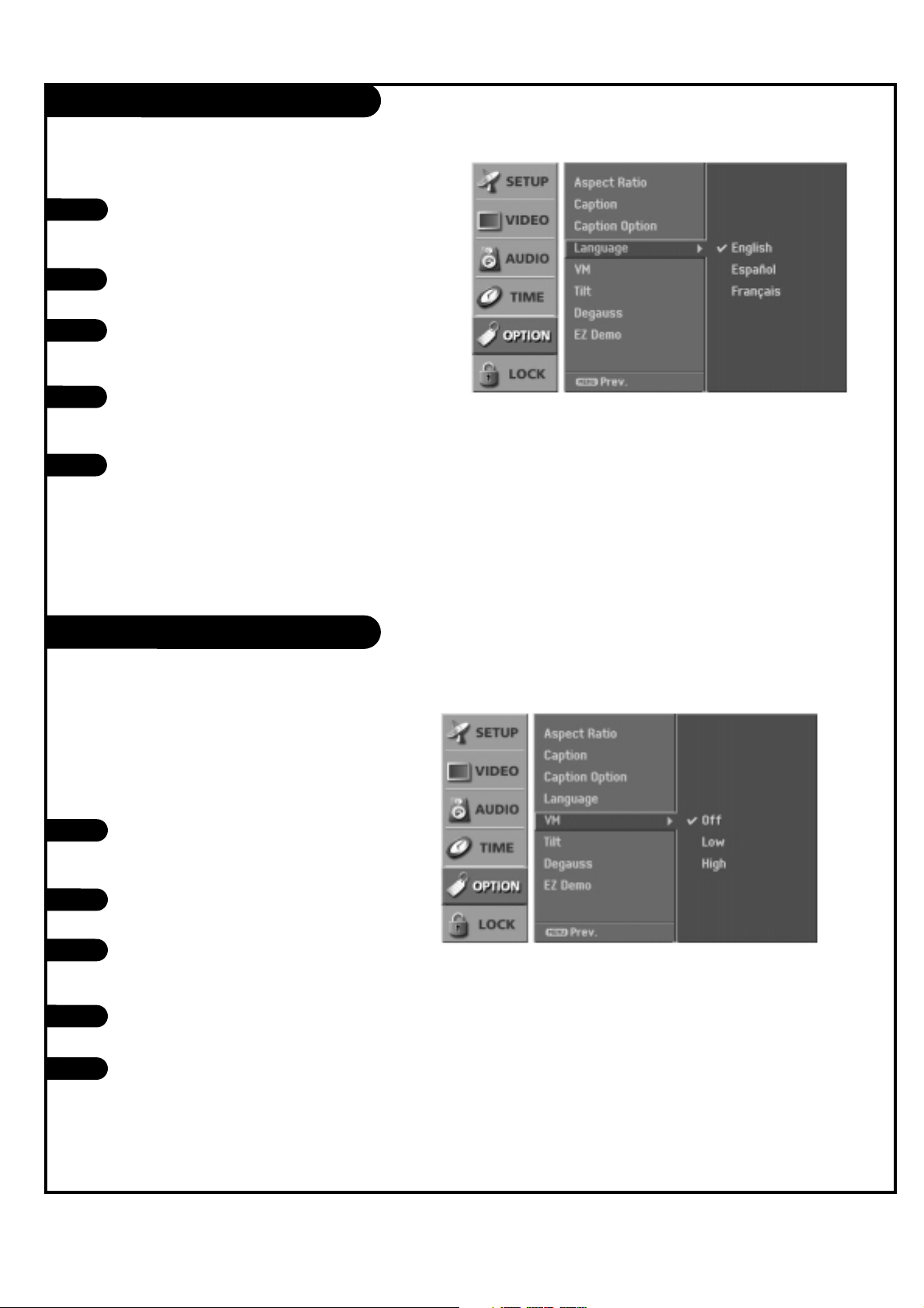
Velocity Modulation
Press the MENU button on the remote
control, then use the UP/DOWN arrow
button to select the Option menu.
Press the RIGHT arrow button to access
the Option menu.
Use the UP/DOWN arrow button to select
VM, and then press the RIGHT arrow button.
Use the UP/DOWN arrow button to select
Off, Low, or High.
Press EXIT button to return to TV viewing
or press MENU button to return to the
previous menu.
1
2
3
4
5
On-Screen Menus Language
Press the MENU button on the remote
control, then use the UP/DOWN arrow
button to select the Option menu.
Press the RIGHT arrow button to go to
the Option menu.
Use the UP/DOWN arrows to choose the
Language, then press the RIGHT arrow
button.
Use the UP/DOWN arrow button to select
the language you want the on screen
menus to appear in.
Press EXIT button to return to TV viewing
or press MENU button to return to the
previous menu.
1
2
3
4
5
S
el
ect
your
Us
e
this
funct
ion
Page 48

PAGE 48
206-03890
Tilt
Degaussing the Screen
Press the MENU button on the remote
control, then use the UP/DOWN arrow
button to select the Option menu.
Press the RIGHT arrow button to access
the Option menu.
Use the UP/DOWN arrow button to select
Tilt, then, use the LEFT/RIGHT arrow button to adjust and correct any Tilt.
Press EXIT button to return to TV viewing
or press MENU button to return to the
previous menu.
1
2
3
4
Th
e
pi
cture
Press the MENU button on the remote
control, then use the UP/DOWN arrow
button to select the Option menu.
Press the RIGHT arrow button to access
the Option menu.
Use the UP/DOWN arrow button to select
Degauss, then press the RIGHT arrow
button to perform the Degauss function.
Press EXIT button to return to TV viewing
or press MENU button to return to the
previous menu.
1
2
3
4
Th
e
magnet
ic
f
i
eld
I
f
Page 49

PAGE 49
206-03890
EZ Demo
Press the MENU button on the remote
control, then use the UP/DOWN arrow
button to select the Option menu.
Press the RIGHT arrow button to access
the Option menu.
Use the UP/DOWN arrow button to select
EZ Demo, then press the RIGHT arrow
button.
Press EXIT button on the remote to stop
EZ Demo.
1
2
3
4
Shows
you how to
nav-
1 2 3
4 5 6
7 8 9
0
tv
mode
light
power
tv/video
comp/dvi
freeze
vcr
cable
dvd
sat
mute
pip inputpipch- pipch+
pip
info
recordstop
pause
rew
play
ff
menu exit
timer cc
swap
vol
ch
surf
audio
video
signalratio
front
skip
dash(-) flashbk
1/3
2/3
1/3
1
Page 50
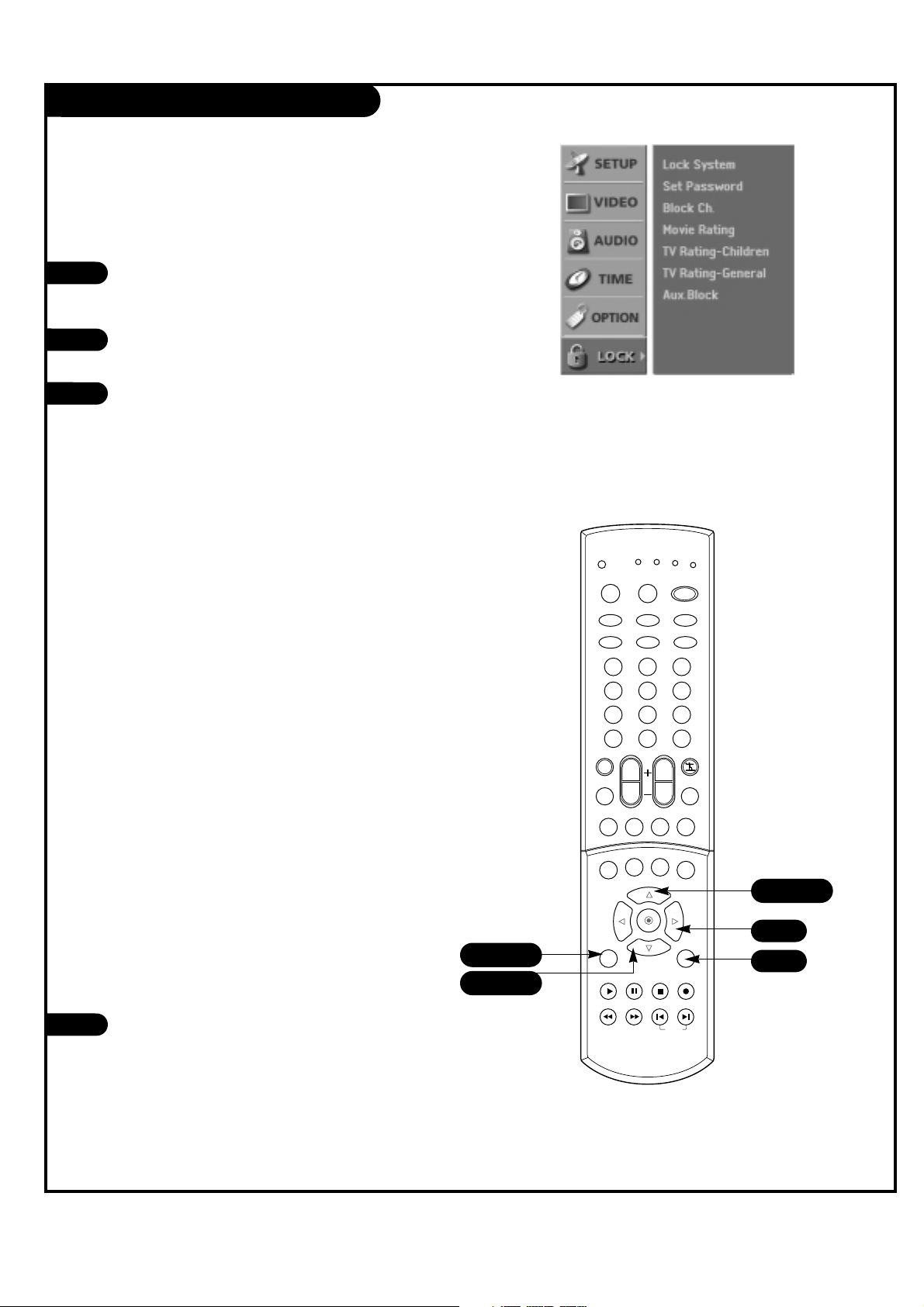
PAGE 50
206-03890
Parental Lock Setup
Press the MENU button on the remote control,
then use the UP/DOWN arrow button to select
the Lock Menu option.
Press the RIGHT arrow button to activate the
Lock Menu.
Use the UP/DOWN arrows to choose from the
following Lock Menu options. Once the options
are selected, change the settings to your preferences.
•
Lock On/Off: Activates or disables the blocking
scheme you set up previously.
• Set Password: Change the password by inputting
a new password twice.
• Movie Rating (MPPA): Blocks movies according
to the movie ratings limits specified, so children
cannot view certain movies. You can set the ratings limit by blocking out all the movies with the
ratings above a specified level. Keep in mind that
the movie ratings limit only applies to movies
shown on TV, not TV programs, such as soap
operas.
• TV Rating-Children: Keeps children from watch-
ing certain TV programs among only the programs
intended for children, according to the ratings
limit. The children rating does not apply to other
TV programs. Unless you block certain TV programs intended for mature audiences in the TV
Rating - sub menu, your children can view those
programs.
• TV Rating-General: Blocks certain TV programs
that you and your family do not want to view,
based on the ratings.
• Aux. Block: Enables you to select a source for
blocking among the source devices you have
hooked up.
Press EXIT button to return to TV viewing or
press MENU button to return to the previous
menu.
1
2
3
4
L
ets you
set
up
block
1 2 3
4 5 6
7 8 9
0
tv
mode
light
power
tv/video
comp/dvi
freeze
vcr
cable
dvd
sat
mute
pip inputpipch- pipch+
pip
info
recordstop
pause
rew
play
ff
menu exit
timer cc
swap
vol
ch
surf
audio
video
signalratio
front
skip
dash(-) flashbk
1/3
1/4
1/3
4
2
Page 51

PAGE 51
206-03890
TV-Y (All Children): Program is appropriate for all children.
TV-Y7 (Directed toward Older Children): Program is designed for children age 7 and above.
TV-G (General audience): Most parents would find this program suitable for all ages.
TV-PG (Parental guidance suggested): Program contains material that parents may find unsuitable for younger children.
TV-14 (Parents strongly cautioned): Program contains some material that many parents would find unsuitable for chil-
dren under 14 years of age.
TV-MA (Mature audience only): Program is specifically designed to be viewed by adults and therefore may be unsuitable
for children under 17.
G (General audiences): All ages can view these programs.
PG (Parental guidance suggested): Some program content may not be suitable for children.
PG-13 (Parents strongly cautioned): Some program content may not be appropriate for children under 13.
R (Restricted): Children under 17 requires parent or adult guardian to be present.
NC-17: No one 17 should be allowed to view the program.
X: For Adult viewing only.
Parental Lock Rating Descriptions
Parental Lock Setup (Continued)
Page 52

PAGE 52
206-03890
Programming the Remote
Test your remote control.
To find out whether your remote control can
operate the component without programming, turn on the component such as a VCR
and press the corresponding mode button
(VCR) on the remote control, while pointing
at the component. Test the POWER and CH
+/- buttons to see if the component
responds properly. If not, the remote
requires programming to operate the device.
Turn on the component to be programmed,
then press the corresponding mode button
on the remote control.
Press the POWER and MUTE buttons simultaneously, the remote control is ready to be
programmed for the code.
There are two ways to find the right code for
the component.
A. If you press the CH +/- buttons repeatedly, the codes will change one at-a-time.
Press the POWER button after each code
change. If the right code is found, the
device will turn off.
B. Enter a code number using the number
buttons on the remote. Programming code
numbers for the corresponding component
can be found on the following pages.
Again, if the code is correct, the device will
turn off.
Press the EXIT button to store the code.
Test the remote control functions to see if
the component responds properly. If not,
repeat from step 2.
1
1 2 3
4 5 6
7 8 9
0
tv
mode
light
power
tv/video
comp/dvi
freeze
vcr
cable
dvd
sat
mute
pip inputpipch- pipch+
pip
info
recordstop
pause
rew
play
ff
menu exit
timer cc
swap
vol
ch
surf
audio
video
signalratio
front
skip
dash(-) flashbk
2
3
4
5
2
3
4
5
6
4
The remote control for your HD receiver is a
multi-brand or universal remote control. It can
be programmed to operate most remote-controllable devices of other manufacturers.
Note that the remote control may not control
all models of other brands.
3/4
Page 53

PAGE 53
206-03890
Programming Codes
TVs
Brand Codes
A MARK 112 143
ADMIRAL 072 081 161
AKAI 006 146
AMPRO 073 167
AMSTRAD 052
ANAM 043 054 056
080 104 108
112 115 118
121 131
AOC 004 006 058
112
BLAUPUNKT 088
CANDLE 002 003 004
006
CAPEHART 058
CETRONIC 043
CITIZEN 002 003 004
006 043 101
103 143
CLASSIC 043
CONCERTO 004
CONTEC 039 043 050
051
CORONADO 143
CRAIG 043 054
CROWN 043 143
CURTIS MATHES 004 006 101
116 143
CXC 043
DAEWOO 004 016 017
043 044 055
071 076 103
107 111 114
117 120 123
125 127 128
136 143
DAYTRON 004 116 143
DYNASTY 043
DYNATECH 062
ELECTROHOME 024 077 143
EMERSON 004 005 006
028 043 047
048 050 051
096 116 143
151 153 154
155
FISHER 007 057
FUNAI 028 043
FUTURETECH 043
GE 004 006 008
009 034 056
073 074 091
116 130 144
155 160 161
165
Brand Codes
GOLDSTAR 004 102 106
110 112 113
116 119 122
127 137 143
HALL MARK 004 116
HITACHI 004 006 009
010 011 012
023 041 075
143 158 163
166
INFINITY 164
INKEL 129
JBL 164
JCPENNY 004 006 008
009 024 030
065 101 143
156 160
JENSEN 013
JVC 034 038 070
083 145
KEC 043
KENWOOD 006 070
KLOSS 002 059
KMC 143
KTV 006 043 143
154
LG 255
LODGENET 072
LOGIK 072
LUXMAN 004
LXI 007 015 052
081 160 164
166
MAGNAVOX 003 004 006
022 059 060
061 063 064
127 143 160
164
MARANTZ 006 077 164
MATSUI 164
MEMOREX 004 007 072
116
METZ 088
MGA 004 006 024
028 042 049
077 116
MINERVA 088
MITSUBISHI 004 006 024
028 040 042
109 116 124
146
MTC 004 006 062
101
NAD 015 025
NEC 006 007 016
Brand Codes
019 024 040
056 130 132
134
NIKEI 043
ONKING 043
ONWA 043
OPTONICA 019 081
PANASONIC 034 056 080
092 164
PHILCO 003 004 006
024 043 056
059 060 063
064 127 143
164
PHILIPS 003 004 005
006 038 059
070 093 143
160 164
PIONEER 006 018 023
025 027 116
135 176
PORTLAND 004 143
PROSCAN 144 160 161
165 167
PROTON 004 058 116
131 143 171
173
QUASAR 034 056 092
RADIO SHACK 019 043 047
116 127 143
RCA 004 006 023
024 056 065
074 144 152
156 160 161
165
REALISTIC 007 019 043
047
ROCTEC 186
RUNCO 168 169
SAMPO 004 006 058
116
SAMSUNG 004 050 089
101 105 113
116 127 133
137 143 160
SANYO 007 020 021
033 039 053
057 082 166
SCOTT 004 028 043
048 116 143
SEARS 004 007 015
028 030 057
082 094 101
116 143 160
Brand Codes
Sharp 004 014 019
022 028 029
081 143 170
175
SIEMENS 088
SIGNATURE 072
SONY 041 070 079
085 126 139
147 185
SOUNDESIGN 003 004 028
043 116
SPECTRICON 112
SSS 004 043
SUPRE MACY 002
SYLVANIA 003 004 006
044 059 060
063 064 116
127 140 160
164
TANDY 081
TATUNG 056 062
TECHNICS 034 080 084
TECHWOOD 004
TEKNIKA 002 003 004
006 024 028
031 043 072
077 101 103
143
TELEFUNKEN 037 046 086
087
TELERENT 072
TERA 172
TMK 004 116
TOSHIBA 007 015 030
040 051 062
101 138
TOTEVISION 143
UNIVERSAL 008 009
VIDEO CONCEPTS 146
VIDIKRON 174
VIDTECH 004 116
WARDS 004 008 009
019 028 060
061 063 064
072 074 116
143 164
YAMAHA 004 006
YORK 004 116
YUPITERU 043
ZENITH 001 072 073
095 103 157
ZONDA 112
Page 54

PAGE 54
206-03890
Programming Codes
VCRs
Brand Codes
AIWA 034
AKAI 016 043 046
124 125 146
AMPRO 072
ANAM 031 033 103
AUDIO DYNAMICS 012 023 039
043
BROKSONIC 035 037 129
CANON 028 031 033
CAPEHART 108
CRAIG 003 040 135
CURTIS MATHES 031 033 041
DAEWOO 005 007 010
064 065 108
110 111 112
116 117 119
DAYTRON 108
DBX 012 023 039
043
DYNATECH 034 053
ELECTROHOME 059
EMERSON 006 017 025
027 029 031
034 035 036
037 046 101
129 131 138
153
FISHER 003 008 009
010
FUNAI 034
GE 031 033 063
072 107 109
144 147
GO VIDEO 132 136
GOLDSTAR 012 013 020
101 106 114
123
HARMAN KARDON 012 045
HITACHI 004 018 026
034 043 063
137 150
INSTANTREPLAY 031 033
JCL 031 033
JCPENNY 012 013 015
033 040 066
101
JENSEN 043
JVC 012 031 033
043 048 050
Brand Codes
055 060 130
150 152
KENWOOD 014 034 039
043 047 048
LG 255
LLOYD 034
LXI 003 009 013
014 017 034
101 106
MAGIN 040
MAGNAVOX 031 033 034
041 067 068
MARANTZ 012 031 033
067 069
MARTA 101
MATSUI 027 030
MEI 031 033
MEMOREX 003 010 014
031 033 034
053 072 101
102 134 139
MGA 045 046 059
MINOLTA 013 020
MITSUBISHI 013 020 045
046 049 051
059 061 151
MTC 034 040
MULTITECH 024 034
NEC 012 023 039
043 048
NORDMENDE 043
OPTONICA 053 054
PANASONIC 066 070 074
083 133 140
145
PENTAX 013 020 031
033 063
PHILCO 031 034 067
PHILIPS 031 033 034
054 067 071
101
PILOT 101
PIONEER 013 021 048
PORTLAND 108
PULSAR 072
QUARTZ 011 014
QUASAR 033 066 075
145
RCA 013 020 033
Brand Codes
034 040 041
062 063 107
109 140 144
145 147
REALISTIC 003 008 010
014 031 033
034 040 053
054 101
RICO 058
RUNCO 148
SALORA 014
SAMSUNG 032 040 102
104 105 107
109 112 113
115 120 122
125
SANSUI 022 043 048
135
SANYO 003 007 010
014 102 134
SCOTT 017 037 112
129 131
SEARS 003 008 009
010 013 014
017 020 031
042 073 081
101
SHARP 031 054 149
SHINTOM 024
SONY 003 009 031
052 056 057
058 076 077
078 149
SOUNDESIGN 034
STS 013
SYLVANIA 031 033 034
059 067
SYMPHONIC 034
TANDY 010 034
TATUNG 039 043
TEAC 034 039 043
TECHNICS 031 033 070
TEKNIKA 019 031 033
034 101
THOMAS 034
TMK 006
TOSHIBA 008 013 042
047 059 082
112 131
Brands Codes
TOTEVISION 040 101
UNITECH 040
VECTOR RESEARCH 012
VICTOR 048
VIDEO CONCEPTS 012 034 046
VIDEOSONIC 040
WARDS 003 013 017
024 031 033
034 040 053
054 131
YAMAHA 012 034 039
043
ZENITH 001 034 048
056 058 072
080 101
Page 55
PAGE 55
206-03890
Programming Codes
SAT
DVD
Brand Codes
ALPHASTAR DSR 123
AMPLICA 050
BIRDVIEW 051 126 129
BSR 053
CAPETRONICS 053
CHANNEL MASTER 013 014 015
018 036 055
CHAPARRAL 008 009 012
077
CITOH 054
CURTIS MATHES 050 145
DRAKE 005 006 007
010 011 052
112 116 141
DX ANTENNA 024 046 056
076
ECHOSTAR 038 040 057
058 093 094
095 096 097
098 099 100
122
ELECTRO HOME 089
EUROPLUS 114
FUJITSU 017 021 022
Brand Codes
027 133 134
GENERAL INSTRUMENT 003 004 016
029 031 059
101
HITACHI 139 140
HOUSTON TRACKER 033 037 039
051 057 104
HUGHES 068
HYTEK 053
JANIEL 060 147
JERROLD 061
KATHREIN 108
LEGEND 057
LG 255
LUTRON 132
LUXOR 062 144
MACOM 010 059 063
064 065
MEMOREX 057
NEXTWAVE 028 124 125
NORSAT 069 070
PACE SKY SATELLITE 143
PANASONIC 060 142
PANSAT 121
Brand Codes
PERSONAL CABLE 117
PHILIPS 071
PICO 105
PRESIDENT 019 102
PRIMESTAR 030 110 111
PROSAT 072
RCA 066 106
REALISTIC 043 074
SAMSUNG 123
SATELLITE SERVICE CO 028 035 047
057 085
SCIENTIFIC ATLANTA 032 138
SONY 103
STARCAST 041
SUPER GUIDE 020 124 125
TEECOM 023 026 075
087 088 090
107 130 137
TOSHIBA 002 127
UNIDEN 016 025 042
043 044 045
048 049 078
079 080 086
101 135 136
Brand Codes
VIEWSTAR 115
WINEGARD 128 146
ZENITH 001 081 082
083 084 091
120
Brand Codes
APEX DIGITAL 022
DENON 020 014
GE 005 006
GOLDSTAR 010 016 025
HARMAN KARDON 027
JVC 012
LG 001 010 016
Brand Codes
025
MAGNAVOX 013
MARANTZ 024
MITSUBISHI 002
NAD 023
ONKYO 008 017
PANASONIC 003 009
Brand Codes
PHILIPS 013
PIONEER 004 026
PROCEED 021
PROSCAN 005 006
RCA 005 006
SAMSUNG 011 015
SONY 007
Brand Codes
THOMPSON 005 006
TOSHIBA 019 008
YAMAHA 009 018
ZENITH 010 016 025
Page 56

PAGE 56
206-03890
Programming Codes
CATV
Brand Codes
ABC 003 004 039
042 046 052
053
ANTRONIK 014
ARCHER 005 007 014
024
CABLE STAR 026
CENTURION 092
CENTURY 007
CITIZEN 007
COLOUR VOICE 065 090
COMBANO 080 081
COMTRONICS 019 030
DIAMOND 023
EAGLE 020 030 040
EASTERN 057 062 066
ELECTRICORD 032
GE 072
GEMINI 008 022 025
054
GI 052 074
GOLDEN CHANNEL 030
HAMLIN 049 050 055
HITACHI 052 055
HOSPITALITY 070 077
JERROLD 002 003 004
Brand Codes
008 009 010
052 069 074
LG 255
M-NET 037
MACOM 033
MAGNAVOX 010 012 064
079
MEMOREX 001
MOVIE TIME 028 032
NSC 015 028 038
071 073
OAK 016 031 037
053
PANASONIC 044 047
PARAGON 001
PHILIPS 006 012 013
020 065 085
090
PIONEER 034 051 052
063 076
POST NEWS WEEK 016
PRUCER 059
PTS 011 048 071
072 073 074
PULSAR 001
RCA 047
Brand Codes
REGAL 049 050
REGENCY 057
REMBRANT 025
RK 091
SAMSUNG 030 068
SCIENTIFIC ATLANTA 003 011 041
042 043 045
046
SHERITECH 022
SIGNAL 030
SIGNATURE 052
SL MARX 030
SPRUCER 047 078
STARCOM 002 004 008
009
STARGATE 008 030
SYLVANIA 067
TADIRAN 030
TANDY 017
TEXSCAN 029 067
TOCOM 039 040 056
TOSHIBA 001
UNIKA 007 014 024
UNITED CABLE 004 053
UNIVERSAL 005 007 014
024 026 027
Brand Codes
032 035
VIEWSTAR 012 015 018
086 087 088
089
ZENITH 001 060 093
Page 57

PAGE 57
206-03890
Maintenance
1. Here’s a great way to keep the dust off your screen for a while. Wet a soft cloth in a mixture of
lukewarm water and a little fabric softener or dish washing detergent. Wring the cloth until it’s
almost dry, and then use it to wipe the screen.
2. Make sure the excess water is off the screen, and then let it air-dry before you turn on your TV.
1. Use a soft cloth with a mild soap solution to wipe the cabinet.
2. Rinse the cloth and wipe the cabinet again.
3. Let the cabinet air-dry before turning the TV on.
If you expect to leave your TV dormant for a long time (such as a vacation), unplug the power cord
from the wall power outlet to protect against possible damage from lightning or power surges. If you
use an off-air antenna, you may also want to disconnect it from the back of your TV before leaving.
SCREEN CLEANING
EXTENDED ABSENCE
CABINET CLEANING
Early malfunctions can be prevented. Careful and regular cleaning can extend the amount of time you will
have your new TV. Be sure to turn the power off and pull out the power cord before you begin any cleaning.
Page 58

PAGE 58
206-03890
Maintenance (Continued)
Even though you may be getting cable, the signal may be weak, which means the quality
of your picture may suffer due to other factors. If there are problems with the image on your TV,
consult the Troubleshooting guide on the following pages. You may also want to contact your cable
service provider to determine if the problem is from the cable service.
If you use your TV to play video games or for other uses that involve single, fixed images, such as
a photo-CD player, you should avoid setting the Brightness level too high.
If static images, like network identification icons or patterns, are left on the screen for a long time
period, they may leave a permanent impression on the TV screen. You can reduce the chance of
this happening by
limiting the amount of time you use the fixed-image display, and by reducing the contrast and
brightness levels.
VIDEO GAMES AND OTHER FIXED-PATTERN DISPLAYS
PICTURE INTERFERENCE
If you
unplug your TV,
you may have to
reset
Page 59

PAGE 59
206-03890
Troubleshooting
SYMPTOM
Snowy picture and unclear sound.
Multiple images or ‘ghost shadows.’
Interference: Sharp lines across
the screen and unclear sound.
Normal picture but no sound.
No picture and unclear sound.
No picture or sound.
No color, but the sound is okay.
Picture has a big black box
on it, but the sound is okay.
Picture has two horizontal
black bars, one on top and
one on bottom.
Missing Secret Lock Code
Some quick and easy tips for fixing problems yourself.
POSSIBLE SOLUTIONS
• Check your antenna connection or location.
• Check your cable input.
• Check to see if the TV/VCR button on your VCR has the TV selected.
• Check your antenna direction and/or location.
• Check your cable input.
• Make sure the cable from your antenna to your TV is
properly connected.
The
following
may cause
image
problems
or
distortion:
Electrical
applianc
es,
powerful
lights, cars,
trucks;
computers
or
portable
phones;
medical
equi
pment
• If possible increase the distance between your TV and the offending appliance,
or shut one of them off.
• Check volume levels.
• Make sure the TV is not Muted.
• Try another channel. The problem may be with the broadcast, not your TV.
• Are the Audio cables installed properly?
• Are the wires for external speakers (if you have external speakers)
installed properly?
• Make sure your speakers are turned on in the Audio menu.
• If your audio mode is set to SAP, the program may not have SAP.
• Are you in TV or cable tuning mode, and should be in the other?
• Make sure output channels on all A/V equipment are on the same channel (3 or 4).
• Check that all connections are tight.
• Is the AC power plugged in?
• Check that your AC power cord outlet works. (Test it by plugging in something
else or try another power outlet.)
Page 60

PAGE 60
206-03890
Troubleshooting (Continued)
SYMPTOM
Remote control doesn’t work.
Menu options can’t be
changed or selected.
No picture or sound
when any non-cable source
is selected.
Weak or no Stereo Sound
when using a stereo VCR.
The PIP inset is black or
lacks contrast.
The PIP inset is “snowy” when
the source is TV.
Time is incorrect.
POSSIBLE SOLUTIONS
• Make sure the batteries are fresh and installed properly.
• Try unplugging your TV for a few minutes,
then plug it back in.
• Check to see if the source equipment has been turned on.
• Make sure that the connections are secure on the back of your TV and on the
source equipment.
• Check to see if all the connections are secure.
• Look in the Audio mode menu to see if all the settings are correct.
• If you are using channel 3 or 4 to view your VCR, stereo sound will not be
available.
• Check to be sure that the PIP source is turned on.
• Check that all the wires are connected properly.
• Check to see if your input source for PIP is set correctly.
• Look to see if the TV/VCR button on your VCR has the TV selected or change
the PIP to another source.
• Make sure the time was set initially. Probably power was lost.
• Reset clock manually.
Page 61

PAGE 61
206-03890
Glossary
A list of definitions for some of the words found in this guide.
75 OHM RF CABLE The round cable that comes from an off-air antenna or cable service
provider. Each end looks like a hex shaped nut with a wire sticking
through the middle, and it screws onto the threaded jack on the back of
your TV.
A/V CABLES Audio/Video cables. Three cables - Right audio (red), Left audio (white),
and Video (yellow). A/V cables are used for stereo playback of videocassettes and for higher quality picture and sound from other A/V devices.
A/V DEVICE Any device that produces video or sound (VCR, DVD, cable box,
or television).
ADD This function lets you add new channels to the channel list in memory
that you’ll scroll through when using your remote.
AMPLIFIER An external device that amplifies sound from a television, CD player, VCR,
DVD or other A/V device.
ANALOG TV Traditional method of representing a television signal as a replica (analog)
of the original picture and sound.
ANTENNA The physical receiver of television signals sent over the air. A large metal
piece of equipment does not always have to be visible for your home to
be using an antenna.
ASPECT RATIO The ratio of the horizontal dimension to the vertical dimension of a pic-
ture. Standard television in the U.S. today is generally transmitted and
displayed in a 4:3 aspect ratio. High-Definition television will normally be
formatted in a wider aspect ratio, assumed to be 16:9.
CAPTIONS A form of subtitling that writes out the dialog for your program on the
screen.
DELETE This function lets you remove channels that you don’t watch from the
channel list in memory.
DIGITAL TV (DTV) A new method of representing a television signal as a series of binary
numbers (1s and 0s). This method allows the signal to be manipulated to
eliminate redundancy and dramatically increase picture and sound quality.
DOLBY DIGITAL Dolby Digital Cinema Sound is made possible by a new digital coding tech-
nique called Dolby AC-3. Dolby AC-3 produces high-quality, 5.1 channel
surround sound which is six discrete separate channels for a full range of
sound. Each channel can carry a different signal simultaneously (front
center, front left, front right, surround left, surround right and subwoofer).
Page 62

PAGE 62
206-03890
Glossary (Continued)
A list of definitions for some of the words found in this guide.
FAVORITE CHANNELS This function created a customized list of your favorite chan-
nels. You can access this group of channels with the SURF button on the remote by pressing SURF repeatedly.
INPUT Refers to the jack that receives a signal into the TV, VCR or
other A/V device.
JACK A connection on the back of a TV, VCR, or any other A/V
device. This includes the RF jacks and the Audio/Video jacks
that are color-coded.
MODE The mode determines the type of device (TV, VCR, Cable, etc.)
that the remote is controlling; remote operating mode.
MONO SOUND Mono (monaural) sound is one channel of sound. On more
than one speaker, all the speakers play the same audio.
OUTPUT Refers to the jack that sends a signal out of a VCR, DVD, or
other A/V device.
PIP This is the most common way to refer to the Picture-In-Picture
(PIP) feature.
SECOND AUDIO Second Audio Programming (SAP) is another, separate, audio
channel available with some programming. Choosing SAP often
refers to listening to audio in another language, such as
Spanish or French.
SIGNAL Picture and sound traveling through cable, or over the air, to
your television screen.
SOURCE The term for the equipment that provides audio and video
information to your TV. Antenna, VCR, DVD players, and Cable
Boxes are examples of sources.
STEREO SOUND Stereo (stereophonic) sound refers to audio that’s divided into
right and left sides.
TEXT Arbitrary text not related to the program.
TUNER Any device that picks up broadcast signals and turns them into
picture and sound.
PROGRAMMING/SAP
Page 63
PAGE 63
206-03890
Product Specifications
Models C34W37
Horizontal Size (inches) 41.7
Height (inches) 24.7
Thickness (inches) 23.2
Weight (lbs) 168.2
Power requirement 120V, 60Hz
Television system American TV Standard, NTSC, ATSC with STB
Television Channel VHF: 2 - 13
UHF: 14 - 69
CATV: 1 - 125
CADTV: 1 - 135
Power consumption (W) 220W
Antenna 75 ohm external terminal for VHF/UHF
Audio Output (W) 7W x 2
Supplied accessories Remote control, batteries 2 size AA (Alkaline battery)
Screen Aspect Ratio 16 : 9
External input ports Video/Audio input (4 set)
Video output (1 set)
S-Video input (3)
Component input (2 set)
Variable audio output (1 set)
DVI-HDTV input (1)
Digital audio optical input (2)
Digital audio optical output (1)
Calibration port (1)
Antenna port (2)
Copyright 2003, Zenith Electronics Corporation
Design
and spec-
ificat
ions are
Page 64

Zenith Part No. 206-03890
P/N : 3828VA0395A (AC02SA)
ZENITH ELECTRONICS CORPORATION
Direct-View TV LIMITED WARRANTY – USA
Zenith will repair or replace your product, at Zenith’s option, if it proves to be defective in material or workmanship under normal use, during the warranty period (“Warranty Period”) listed below, effective from the
date (“Date of Purchase”) of original consumer purchase of the product. This warranty is good only to the
original purchaser of the product and effective only when used in the United States, excluding U.S. Territories.
THIS WARRANTY IS IN LIEU OF ANY OTHER WARRANTIES, EXPRESS OR IMPLIED, INCLUDING
WITHOUT LIMITATION, ANY WARRANTY OF MERCHANTABILITY OR FITNESS FOR A PARTICULAR
PURPOSE. TO THE EXTENT ANY IMPLIED WARRANTY IS REQUIRED BY LAW, IT IS LIMITED IN
DURATION TO THE EXPRESS WARRANTY PERIOD ABOVE. ZENITH WILL NOT BE LIABLE FOR ANY
INCIDENTAL, CONSEQUENTIAL, INDIRECT, SPECIAL OR PUNITIVE DAMAGES OF ANY NATURE,
EVEN IF ADVISED OF THE POSSIBILITY OF SUCH DAMAGES, INCLUDING WITHOUT LIMITATION,
LOST REVENUES OR PROFITS, LOST OR CORRUPTED PROGRAMMING OR DATA, OR ANY OTHER
DAMAGE WHETHER BASED IN CONTRACT, TORT, OR OTHERWISE. Some states do not allow the
exclusion or limitation of incidental or consequential damages or limitation on how long an implied warranty lasts, so the above exclusion or limitation may not apply to you. This warranty gives you specific legal
rights and you may also have other rights that may vary from state to state.
• Damages or operating problems that result from shipping, installation, adjustment of user controls,
calibration, maintenance or failure to maintain, or separate system components; and
• Damages or operating problems that result from normal wear and tear, misuse, abuse, operation outside environmental specifications or contrary to the requirements or precautions in the Operating Guide, accident, lightning strikes or other natural causes, unauthorized modification or alteration, incorrect electrical current or voltage, reception problem caused by inadequate home antenna or faulty antenna connections, computer software, institutional or commercial use, or other causes not arising out of defect in material or workmanship.
The cost of repair or replacement under these excluded circumstances shall be borne by the consumer.
ZENITH ELECTRONICS CORPORATION
2000 MILLBROOK DRIVE
LINCOLNSHIRE, IL 60069
THIS LIMITED WARRANTY DOES NOT APPLY TO:
CUSTOMER INTERACTIVE CENTER NUMBERS:
For nearest Authorized Service
Center, Where to buy, Product
Assistance, or Customer
Assistance
Call 1-877-9Zenith (1-877-993-6484) (Monday - Friday, 7 AM - 8 PM
CT and Saturday, 8 AM - 5 PM CT) and select an appropriate option
from the menu.
Or visit our website at http://www.zenithservice.com
WARRANTY PERIOD:
LABOR: 90 days from the Date of Purchase.
PARTS: One Year from the Date of Purchase.
PICTURE TUBES: 2 Years from the Date of
Purchase.
*
Parts replaced are warranted for the remaining portion of the original warranty period.
HOW SERVICE IS HANDLED:
In-Home Service: Please retain dealer’s dated bill of sale or
delivery ticket as evidence of the Date of Purchase for proof of
warranty, and submit a copy of the bill of sale to the service person
at the time warranty service is provided.
Please call 1-877-9Zenith (1-877-993-6484) to locate
your nearest Zenith Authorized Service Center.
Replacement parts may be new or factory remanufactured.
Visit our website at http://www.zenithservice.com
b
 Loading...