

Page 1

© Copyright 2002, Zenith Electronics Corporation
Operating Guide | Warranty
Model Numbers | C32V23, C36V23, C34W23 | Digital TVs
Page 2
WARNING:
TO REDUCE THE RISK OF ELECTRIC SHOCK DO NOT REMOVE COVER (OR BACK). NO USER SERVICEABLE PARTS INSIDE.
REFER SERVICING TO QUALIFIED SERVICE PERSONNEL.
The lightning flash with arrowhead symbol, within an equilateral triangle, is intended to alert the user to the presence of
uninsulated “dangerous voltage” within the product’s enclosure that may be of sufficient magnitude to constitute a risk of
electric shock to persons.
The exclamation point within an equilateral triangle is intended to alert the user to the presence of important operating and
maintenance (servicing) instructions in the literature accompanying the appliance.
WARNING:
TO PREVENT FIRE OR SHOCK HAZARDS, DO NOT EXPOSE THIS PRODUCT TO RAIN OR MOISTURE.
POWER CORD POLARIZATION:
CAUTION: TO PREVENT ELECTRIC SHOCK, MATCH WIDE BLADE OF PLUG TO WIDE SLOT, FULLY INSERT.
ATTENTION: POUR ÉVITER LES CHOCS ÉLECTRIQUES, INTRODUIRE LA LAME LA PLUS LARGE DE LA FICHE DANS LA BORNE
CORRESPONDANTE DE LA PRISE ET POUSSER JUSQU’AU FOND.
NOTE TO CABLE/TV INSTALLER:
This reminder is provided to call the cable TV system installer’s attention to Article 820-40 of the National Electric Code
(U.S.A.). The code provides guidelines for proper grounding and, in particular, specifies that the cable ground shall be
connected to the grounding system of the building, as close to the point of the cable entry as practical.
REGULATORY INFORMATION:
This equipment has been tested and found to comply with the limits for a Class B digital device, pursuant to Part 15
of the FCC Rules. These limits are designed to provide reasonable protection against harmful interference when the
equipment is operated in a residential installation. This equipment generates, uses and can radiate radio frequency
energy and, if not installed and used in accordance with the instruction manual, may cause harmful interference to radio
communications. However, there is no guarantee that interference will not occur in a particular installation. If this
equipment does cause harmful interference to radio or television reception, which can be determined by turning
the equipment off and on, the user is encouraged to try to correct the interference by one or more of the following
measures:
• Reorient or relocate the receiving antenna.
• Increase the separation between the equipment and receiver.
• Connect the equipment into an outlet on a circuit different from that to which the receiver is connected.
• Consult the dealer or an experienced radio/TV technician for help.
CAUTION:
Do not attempt to modify this product in any way without written authorization from Zenith Electronics Corporation.
Unauthorized modification could void the user’s authority to operate this product.
COMPLIANCE:
The responsible party for this product’s compliance is:
Zenith Electronics Corporation, 2000 Millbrook Drive, Lincolnshire, IL 60069, USA • Phone: 1-847-941-8000.
RECORD YOUR MODEL NUMBER
The model and serial number of your
Entertainment MachineTMare located on the
back of the TV cabinet. For your future convenience, we suggest that you record these numbers here:
Model No._________________________
Serial No. __________________________
WARNING
RISK OF ELECTRIC SHOCK
DO NOT OPEN
Entertainment MachineTMis a trademark of Zenith Electronics Corporation
© Copyright 2002 Zenith Electronics Corporation
Dolby Digital®
Manufactured under license from Dolby Laboratories.
“Dolby” and the double-D symbol are trademarks of Dolby Laboratories.
Confidential Unpublished Works. ©1992 - 1997 Dolby Laboratories, Inc. All rights reserved.
Page 3

IMPORTANT SAFETY INSTRUCTIONS
Important safeguards for you and your new product
Your product has been manufactured and tested with your safety in mind. However, improper use can result in potential
electrical shock or fire hazards. To avoid defeating the safeguards that have been built into your new product, please read
and observe the following safety points when installing and using your new product, and save them for future reference.
Observing the simple precautions discussed in this operating guide can help you get many years of enjoyment and safe operation that are built into your new product.
This product complies with all applicable U.S. Federal safety requirements, and those of the Canadian Standards Association.
PORTABLE CART WARNING
(Continued on next page)
PAGE 3
1. Read Instructions
All the safety and operating instructions should be read
before the product is operated.
2. Follow Instructions
All operating and use instructions should be followed.
3. Retain Instructions
The safety and operating instructions should be retained for
future reference.
4. Heed Warnings
All warnings on the product and in the operating instructions should be adhered to.
5. Cleaning
Unplug this product from the wall outlet before cleaning.
Do not use liquid cleaners or aerosol cleaners. Use a damp
cloth for cleaning.
6. Water and Moisture
Do not use this product near water for example, near a bath
tub, wash bowl, kitchen sink, or laundry tub, in a wet basement, or near a swimming pool.
7. Accessories, Carts, and Stands
Do not place this product on a slippery or tilted surface, or
on an unstable cart, stand, tripod, bracket, or table. The
product may slide or fall, causing serious injury to a child
or adult, and serious damage to the product. Use only with
a cart, stand, tripod, bracket, or table recommended by the
manufacturer, or sold with the product. Any mounting of
the product should follow the manufacturer’s instructions,
and should use a mounting accessory recommended by the
manufacturer.
8. Transporting Product
A product and cart combination should be moved with care.
Quick stops, excessive force, and uneven surfaces may
cause the product and cart combination to overturn.
9. Attachments
Do not use attachments not recommended by the product
manufacturer as they may cause hazards.
10. Ventilation
Slots and openings in the cabinet are provided for
ventilation and to ensure reliable operation of the product
and to protect it from overheating, and these openings
must not be blocked or covered. The openings should never
be blocked by placing the product on a bed, sofa, rug, or
other similar surface. This product should not be placed in
a built-in installation such as a bookcase or rack unless
proper ventilation is provided or the manufacturer’s instructions have been adhered to.
11. Power Sources
This product should be operated only from the type of
power source indicated on the marking label. If you are not
sure of the type of power supply to your home,
consult your product dealer or local power company. For
products intended to operate from battery power, or other
sources, refer to the operating instructions.
12. Power Cord Polarization
This product is equipped with a polarized alternating - current power plug (a plug having one blade wider than the
other). This plug will fit into the power outlet only one
way. This is a safety feature. If you are unable to insert the
plug fully into the outlet, try reversing the plug. If the
plug should still fail to fit, contact your electrician to
replace your obsolete outlet. Do not defeat the safety purpose of the polarized plug.
13. Power Cord Protection
Power-supply cords should be routed so that they are not
likely to be walked on or pinched by items placed upon or
against them, paying particular attention to cords at plugs,
convenience receptacles, and the point where they exit
from the product.
206-3706 2-WR-POLZ
Page 4
PAGE 4
3-WireRev6/00
IMPORTANT SAFETY INSTRUCTIONS
(Continued from previous page)
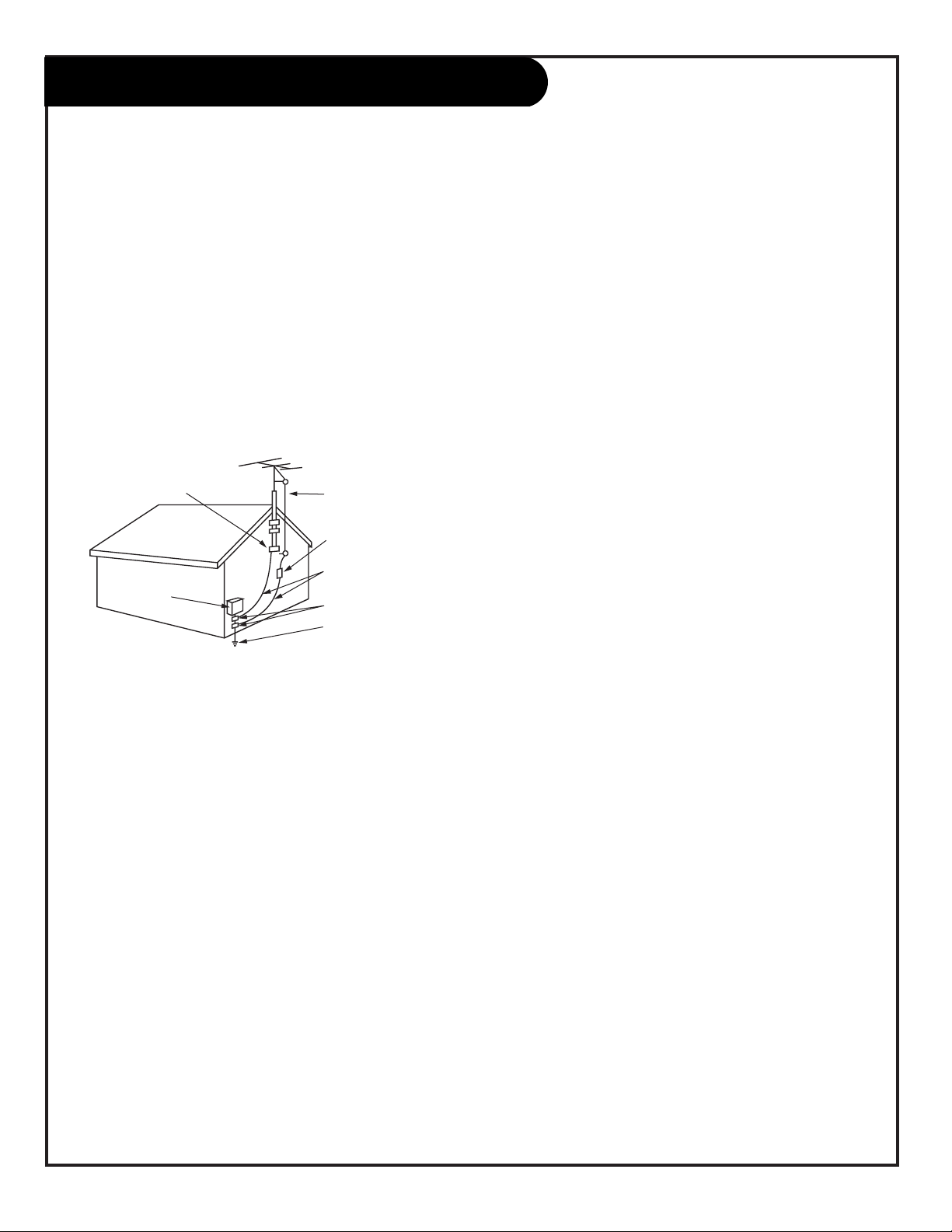
14. Outdoor Antenna Grounding
If an outside antenna or cable system is connected to the
product, be sure the antenna or cable system is grounded so
as to provide some protection against voltage surges and
built-up static charges. Article 810 of the National Electrical
Code (U.S.A.), ANSI/ NFPA 70 provides information with
regard to proper grounding of the mast and supporting
structure, grounding of the lead-in wire to an antenna discharge unit, size of grounding conductors, location of
antenna-discharge unit, connection to grounding electrodes,
and requirements for the grounding electrode.
15. Lightning
For added protection for this product (receiver) during a
lightning storm, or when it is left unattended and unused
for long periods of time, unplug it from the wall outlet and
disconnect the antenna or cable system. This will prevent
damage to the product due to lightning and power-line
surges.
16. Power Lines
An outside antenna system should not be located in the
vicinity of overhead power lines or other electric light or
power circuits, or where it can fall into such power lines or
circuits. When installing an outside antenna system, extreme
care should be taken to keep from touching such power
lines or circuits as contact with them might be fatal.
17. Overloading
Do not overload wall outlets and extension cords as this can
result in a risk of fire or electric shock.
18. Object and Liquid Entry
Never push objects of any kind into this product through
openings as they may touch dangerous voltage points or
short-out parts that could result in a fire or electric shock.
Never spill liquid of any kind on the product.
19. Servicing
Do not attempt to service this product yourself as opening
or removing covers may expose you to dangerous voltage or
other hazards. Refer all servicing to qualified service personnel.
20. Damage Requiring Service
Unplug this product from the wall outlet and refer servicing
to qualified service personnel under the following conditions:
a. If the power-supply cord or plug is damaged.
b. If liquid has been spilled, or objects have fallen into the
product.
c. If the product has been exposed to rain or water.
d. If the product does not operate normally by following
the operating instructions. Adjust only those controls that
are covered by the operating instructions as an improper
adjustment of other controls may result in damage and will
often require extensive work by a qualified technician to
restore the product to its normal operation.
e. If the product has been dropped or the cabinet has been
damaged.
f. If the product exhibits a distinct change in performance.
21. Replacement Parts
When replacement parts are required, be sure the service
technician has used replacement parts specified by the manufacturer or have the same characteristics as the original
part. Unauthorized substitutions may result in fire, electric
shock, or other hazards.
22. Safety Check
Upon completion of any service or repairs to this product,
ask the service technician to perform safety checks to determine that the product is in proper operating condition.
23. Wall or Ceiling Mounting
The product should be mounted to a wall or ceiling only as
recommended by the manufacturer. The product may slide or
fall, causing serious injury to a child or adult, and serious
damage to the product.
24. Heat
The product should be situated away from heat sources such
as radiators, heat registers, stoves, or other products
(including amplifiers) that produce heat.
Antenna Lead in Wire
Antenna Discharge Unit
(NEC Section 810-20)
Grounding Conductor
(NEC Section 810-21)
Ground Clamps
Power Service Grounding
Electrode System (NEC
Art 250, Part H)
Ground Clamp
Electric Service
Equipment
Example of Grounding According to National Electrical
Code Instructions
NEC - National Electrical Code
Page 5

Table of Contents
Refer to the information below to hook up external equipment and set up the features on your
TV. As a aid to installing and setting up your TV, see the Setup Checklist on the next page...
Safety Warnings . . . . . . . . . . . . . . . . . . . . . . . . . . . . . . . . 2
Important Safety Information . . . . . . . . . . . . . . . . . . . . 3 - 4
Table of Contents . . . . . . . . . . . . . . . . . . . . . . . . . . . . . . . 5
Step 1. Hook Up TV
Setup Checklist (what you need to do to get the TV working) . . 6
Connection Panel Jacks Overview . . . . . . . . . . . . . . . . . . . . 7
Equipment Connection Options
Antenna, Install batteries in remote . . . . . . . . . . . . . . . . . . . 8
Cable Service, Install batteries in remote . . . . . . . . . . . . . . . . 9
Antenna with VCR, Install batteries in remote control . . . . . . 10
Cable Service with VCR, Install batteries in remote control . . . 11
S-VHS VCR, Install batteries in remote control . . . . . . . . . . . 12
DVD Component Video Hook up . . . . . . . . . . . . . . . . . . . . . 13
High-Definition Hook up . . . . . . . . . . . . . . . . . . . . . . . . . 14
Audio/Video Signal Output . . . . . . . . . . . . . . . . . . . . . . . . 15
Digital Audio Output . . . . . . . . . . . . . . . . . . . . . . . . . . . 16
Front Panel Controls/Inputs . . . . . . . . . . . . . . . . . . . . . . . 17
Step 2. Reception Setup and Channel Search
EZ Scan, Select: Antenna, DTV, or Cable service and let the channel
search memorize channels in your area . . . . . . . . . . . . . . 18
Remote Control Key Functions in TV mode . . . . . . . . . . . . . . 19
On-Screen Menu Operation with Remote . . . . . . . . . . . . . . . 20
Source Selection Options . . . . . . . . . . . . . . . . . . . . . . . . . 21
On-Screen Menus/Displays Overview . . . . . . . . . . . . . . . 22 - 23
Other Functions and On-Screen Displays . . . . . . . . . . . . . . . 24
Step 3. Customize the TV’s Features
Setup Menu (Start with page 18, EZ Scan)
Channel Edit . . . . . . . . . . . . . . . . . . . . . . . . . . . . . . . 25
DTV Signal . . . . . . . . . . . . . . . . . . . . . . . . . . . . . . . . 26
Tilt . . . . . . . . . . . . . . . . . . . . . . . . . . . . . . . . . . . . . 27
Channel Labels . . . . . . . . . . . . . . . . . . . . . . . . . . . . . 28
Input Source . . . . . . . . . . . . . . . . . . . . . . . . . . . . . . . 29
Video Menu . . . . . . . . . . . . . . . . . . . . . . . . . . . . . . . . . 30
EZ Picture: (Custom, Normal, Digital Preset, Night Time, Movie,
Weak Signal, Video Game, Sports), Contrast, Brightness, Color,
Tint, Sharpness, Color Temp, Z-View
Audio Menu . . . . . . . . . . . . . . . . . . . . . . . . . . . . . . . . . 31
Audio Mode: (Mono, Stereo, SAP), EZ SoundRite, EZ Sound:
(Custom, Normal, Stadium, News, Music, Theater) Balance,
Treble, Bass, Speakers, Front Surround.
Time Menu
Clock . . . . . . . . . . . . . . . . . . . . . . . . . . . . . . . . . . . 32
Off Timer . . . . . . . . . . . . . . . . . . . . . . . . . . . . . . . . 33
On Timer . . . . . . . . . . . . . . . . . . . . . . . . . . . . . . . . . 33
Sleep Timer . . . . . . . . . . . . . . . . . . . . . . . . . . . . . . . 34
Special Menu
Aspect Ratio . . . . . . . . . . . . . . . . . . . . . . . . . . . . . . . 35
Analog Caption . . . . . . . . . . . . . . . . . . . . . . . . . . . . . 36
Language . . . . . . . . . . . . . . . . . . . . . . . . . . . . . . . . . 37
EZ Demo (On-screen menus/displays overview) . . . . . . . . . 38
Lock (Parental Control Menu) . . . . . . . . . . . . . . . 39 - 40 - 41
Restricts viewer programming.
Remote Control Programming
Set up remote to operate other devices . . . . . . . . . . . . . 42
Mode Sound Switch Setup . . . . . . . . . . . . . . . . . . . . . . 43
Verify Mode’s 3-Digit Code . . . . . . . . . . . . . . . . . . . . . . 44
AutoSearch . . . . . . . . . . . . . . . . . . . . . . . . . . . . . . . 45
Programming Product Brand Codes . . . . . . . . . . . . . 46 - 47
Remote Modes Key Functions . . . . . . . . . . . . . . . . . . . . 48
Maintenance . . . . . . . . . . . . . . . . . . . . . . . . . . . . . . . . . 49
Troubleshooting . . . . . . . . . . . . . . . . . . . . . . . . . 50 - 51 - 52
Glossary . . . . . . . . . . . . . . . . . . . . . . . . . . . . . . . . . . . . 53
Notes . . . . . . . . . . . . . . . . . . . . . . . . . . . . . . . . . . 54 - 55
Zenith Warranty . . . . . . . . . . . . . . . . . . . . . . . . . Back Cover
Note: Design and specifications are subject to change without prior notice.
PAGE 5
Step 1. Hook up external equipment and antenna or cable service wires to the TV. Install batteries in the remote
control. After all connections have been made, plug your TV into standard household power, see pages 7 thru 17.
Step 2. Go to page 18 to use EZ Scan. (Search for and memorize all the channels available in your area.)
Step 3. Set up all other TV options see pages listed below.
Dolby Digital®
Manufactured under license from Dolby Laboratories.
“Dolby” and the double-D symbol are trademarks of Dolby Laboratories.
Confidential Unpublished Works. ©1992 - 1997 Dolby Laboratories, Inc. All rights reserved.
Page 6

206-3767
PAGE 6
Setup and Operation Checklist
Setup and Operation Checklist
(See page 5 for available connection and operational setup options.)
1. Unpack TV and all accessories.
2. Connect your TV to input sources: antenna and all video source equipment.
See pages 7 - 14.
3. Connect TV output to all external video and audio equipment
see pages 7, 15, 16.
4. Install batteries in remote control.
See any page 8 through 14.
5. Plug TV and source equipment into power outlets.
See pages 8 through 14.
6. Turn TV on.
See pages 17 (Front Panel) and 19 (Remote Control).
7. Choose on screen menu language.
See page 37. (English is selected.)
8. Use EZ Scan* to search for all channels in your area.
See page 18.
9. Turn video source equipment on.
10. Select viewing source for TV.
See pages 21 and 29
11. Fine-tune source image and sound to personal preference or as required by source.
See pages 30, 31, and 35.
12. Additional features Setup
See Table of Contents.
*EZ Scan/Channel Search Notes -Available Channels/Active Channels/DTV Channels
EZ Scan finds channels which have a signal present and are actively being broadcast. Some broadcasters do not provide or send or broadcast a signal continuously. As a result, some DTV channels may not be found with EZ Scan. If you know that there is a DTV channel that
was not found by EZ Scan, run EZ Scan again; when the DTV channel is actually sending out a program.
Page 7
206-3767
PAGE 7
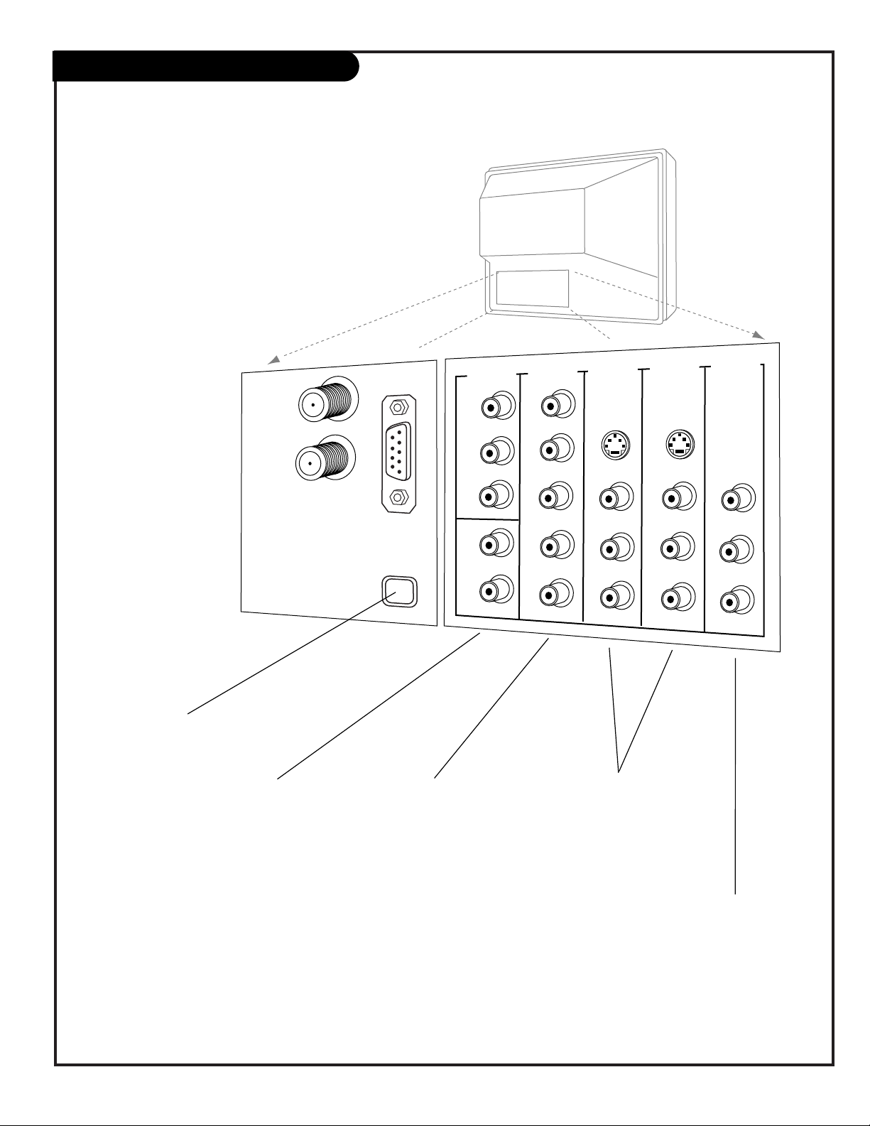
“Source” Connection Panel Overview
Use this page for reference to connect: High
Definition equipment, Standard Definition equipment,
DVD Player, and VHS equipment.
To hook up source equipment, see below and also
refer to the Table of Contents on page 5; shows pages
to go to for equipment hookup options. Also, see the
front connections panel source’s hookup options on
page 17.
After you have finished hooking up your source
equipment, go to page 18 and use EZ Scan to search
for and find all the available channels in
your area.
TV Back
Pr
Pb
Y
R
L
P
r
Pb
Y
R
L
R
L
R
L
R
L
VIDEO 2
IN
VIDEO 1
IN
HD IN
(1080i)
MONITOR
OUTPUT
AUDIO
AUDIO
AUDIO
AUDIO
AUDIO
VIDEO
VIDEO
VIDEO
S-VIDEO 1
S-VIDEO 2
ANTENNA/
CABLE 1
ANTENNA
2
DIGITAL AUDIO
OUTPUT
OPTICAL
DVD IN
(480i)
CALIBRATION
VIDEO 1 IN VIDEO 2 IN
Connect your Audio/Video or
S-Video equipment to these
jacks.
See pages 10, 11, 12.
HD IN
1080i
Connect high-definition
component video equipment here.
-EDTV Set top Box, 1080i
-HDTV Set top Box, 1080i
See page 14.
ANTENNA/CABLE 1
ANTENNA 2
Use Antenna/Cable 1 to
hookup an antenna or
cable system.
See pages 8, 9, 10, 11, 12.
To hookup both digital
and analog sources, use
ANTENNA/CABLE 1 and
ANTENNA 2.
Refer to EZ Scan on page
18, to see digital and ana-
log hookup options.
DIGITAL AUDIO
OPTICAL OUTPUT
Connects to external
audio equipment like a
stereo system.
See page 16.
DVD IN
480i
Connect standard component video equipment
or DVD player here.
-DVD Player, 480i
-SDTV Set top Box, 480i
See page 13.
VIDEO / R - L AUDIO OUT
Use these output jacks to connect
external audio/video equipment.
See page 15.
Important Antenna/Cable-Digital/Analog Connections Note:
If you use both digital and analog equipment to receive your TV
channels, use both Antenna/Cable 1 and Antenna 2 jacks. Refer to
EZ Scan on page 18, to see digital and analog hookup options.
Page 8

206-3767
PAGE 8
Mini glossary
75 OHM RF CABLE The wire that comes from an off-air antenna or cable service provider. Each end looks like a hex shaped nut with a wire
sticking through the middle, and it screws onto the threaded antenna/cable jack on the back of your TV.
A small device that connects a two-wire 300 ohm antenna to a 75 ohm RF jack. They are usually about an inch long with two screws
on one end and a round opening with a wire sticking out on the other end.
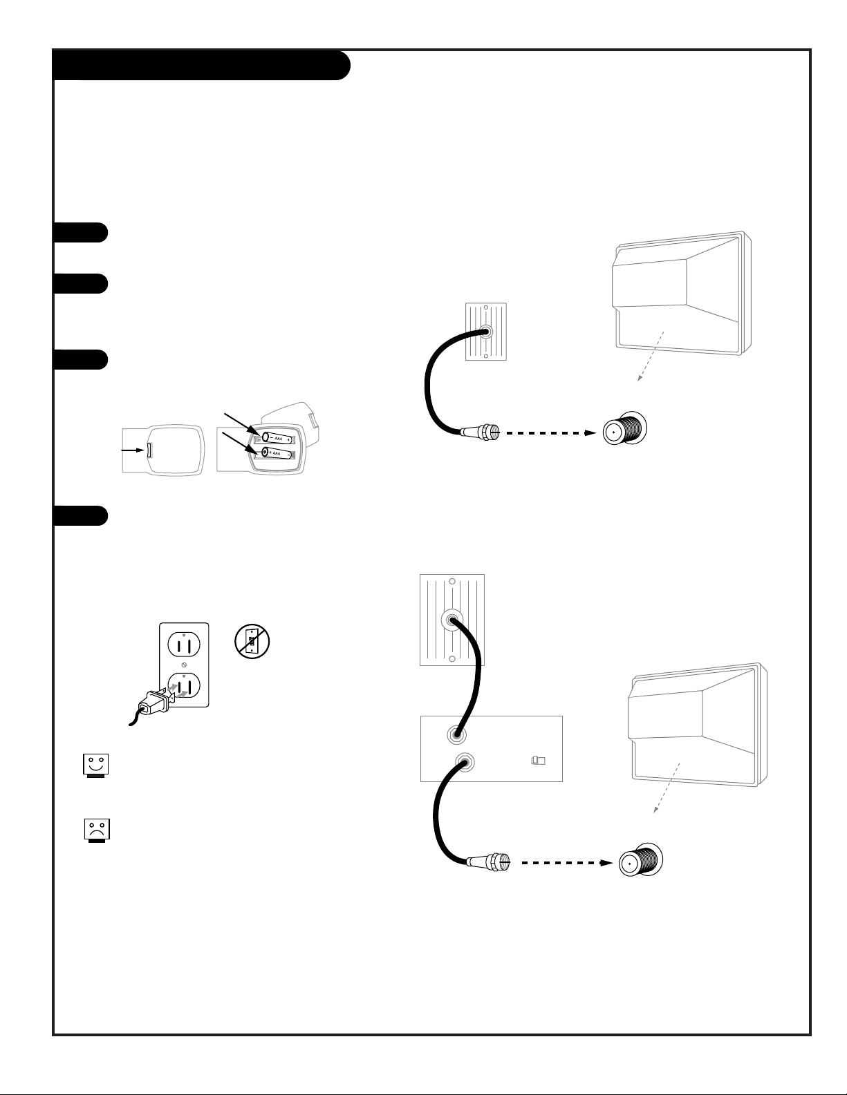
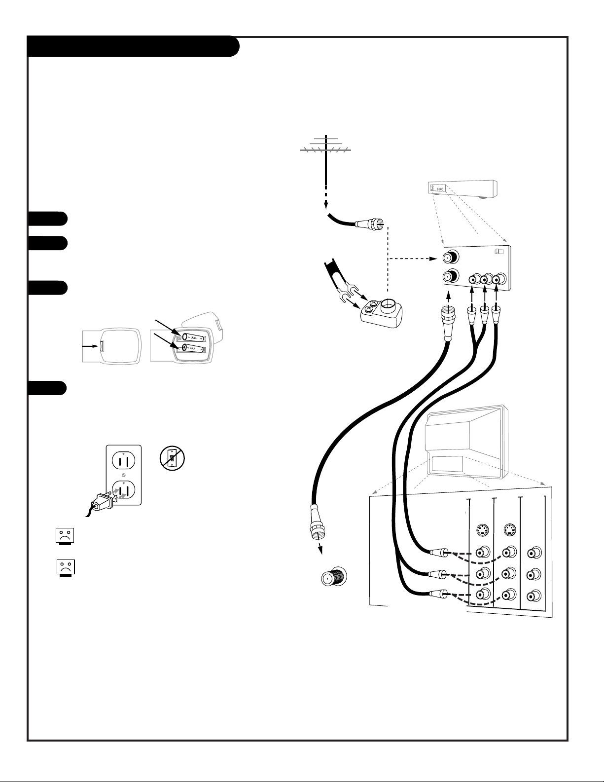
Hook Up an Off-Air Antenna
Connect an off-air antenna
If you have a 75 ohm RF cable, then you don’t need
any adapters!
A 300 to 75 ohm adapter is not included with the TV.
300 TO 75 OHM
ADAPTER
Typical
TV Back
Flat Wire
(300 ohm)
Antenna
300/75 ohm
Adapter
ANTENNA/
CABLE 1
RF Coaxial Wire
(75ohm)
Antenna
Typical
TV Back
ANTENNA/
CABLE 1
Locate the Antenna/Cable 1 jack on the back
of your TV.
Connect the antenna wire that runs from the
wall directly to this jack, according to one of
the diagrams to the right.
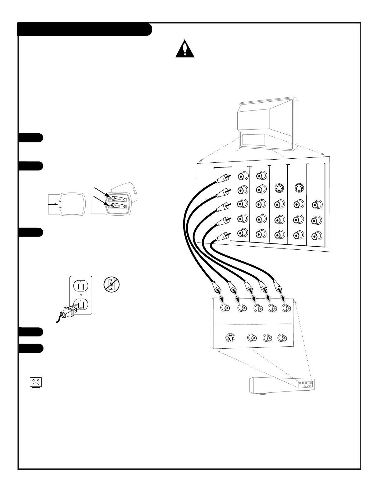
Remove the back of the remote and put in two
“AAA” batteries.
Plug in your TV. Your TV is designed to operate
on standard household current, 120-volt 60
Hertz AC. Do not plug it into an outlet controlled by a switch. Do not attempt to operate
it on DC power.
Back of
Remote
120 V AC
60 Hz
1
2
3
4
Page 9
206-3767
PAGE 9
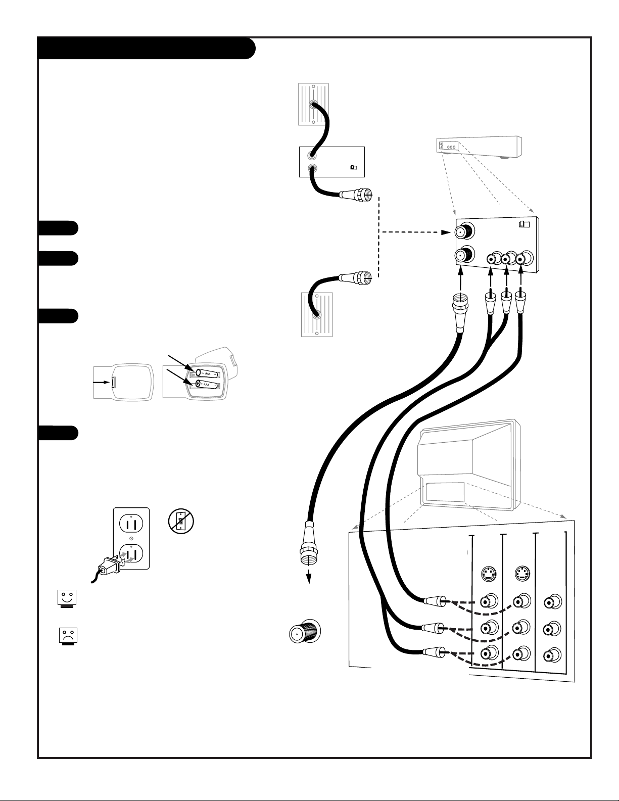
Hook Up Cable Service (CATV)
If you’re using a cable box, leave the TV on
channel 3 or 4 and use your cable box to
change channels.
If you’re using a cable box, EZ Scan might only
find the channel your cable service is on (usually channel 3 or 4). Don’t worry, that’s all you
need!
Typical
Cable TV
Wall Jack
Coaxial Round Wire
(75ohm)
Typical
TV Back
ANTENNA/
CABLE 1
Typical
Cable TV
Wall Jack
Cable Box
In
Out
RF Coaxial Wire
(75ohm)
3 4
output
switch
Typical
TV Back
ANTENNA/
CABLE 1
Locate the Antenna/Cable jack on the
back of the TV.
Connect the cable service wire that runs
from the wall or cable box directly to this
jack, according to one of the diagrams to
the right.
Remove the back of the remote and put in
two “AAA” batteries.
Plug in your TV. Your TV is designed to
operate on standard household current,
120-volt 60 Hertz AC. Do not plug it into
an outlet controlled by a switch. Do not
attempt to operate it on DC power.
120 V AC
60 Hz
1
2
3
4
Connect cable service to your Entertainment Machine
Back of
Remote
Page 10
PAGE 10
206-3767
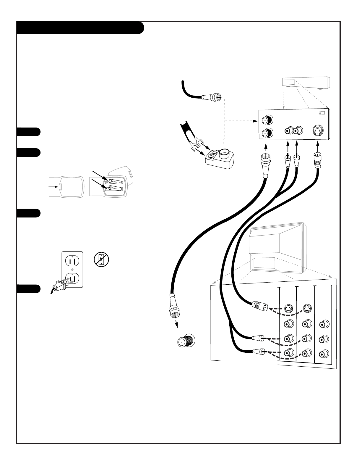
Hook Up a VCR
Connect a VCR to your TV
No adapters or A/V cables are included with the TV. See
your Zenith dealer to purchase any adapters or cables.
Without A/V cables, most VCRs will not play
videocassettes in stereo sound.
TV Back
Pr
Pb
Y
R
L
P
r
Pb
Y
R
L
R
L
R
L
R
L
RGB
VIDEO 2
IN
VIDEO 1
IN
DVD IN
HD IN
MONITOR
OUTPUT
AUDIO
AUDIO
AUDIO
AUDIO
AUDIO
VIDEO
VIDEO
VIDEO
S-VIDEO 1
S-VIDEO 2
ANTENNA/
CABLE 1
In
Out
Audio
Video
3 4
VCR Back
VCR Back AV Panel
output
switch
Typical
Antennas:
Flat or
Round Wire
Flat Wire
(300 ohm)
300/75 ohm
Adapter
RF Coaxial Round Wire
(75ohm)
Connect your VCR to the
Video 1 or Video 2 set of input jacks
Locate the Antenna In jack on the back of the VCR.
Connect the wire that runs from the antenna, according to the diagram to the right. Make any other connections as necessary.
Remove the back of the remote and put in two “AAA”
batteries.
Plug in your TV. Your TV is designed to operate on
standard household current, 120-volt 60 Hertz AC. Do
not plug it into an outlet controlled by a switch. Do
not attempt to operate it on DC power.
120 V AC
60 Hz
1
2
3
Back of
Remote
4
Page 11
PAGE 11
206-3767
Hook Up Cable Service (CATV) and VCR
Connect Cable service and a VCR to the TV
Tune both the VCR and the television to channel 3
or 4 (cable box output channel) and use the cable
box to change channels.
No A/V cables are included with your TV. Without
A/V cable hookups, most VCRs will not play
videocassettes in stereo sound.
TV Back
Pr
Pb
Y
R
L
P
r
Pb
Y
R
L
R
L
R
L
R
L
RGB
VIDEO 2
IN
VIDEO 1
IN
DVD IN
HD IN
MONITOR
OUTPUT
AUDIO
AUDIO
AUDIO
AUDIO
AUDIO
VIDEO
VIDEO
VIDEO
S-VIDEO 1
S-VIDEO 2
ANTENNA/
CABLE 1
In
Out
Audio
Video
3 4
VCR Back
VCR Back AV Panel
output
switch
Typical
Cable TV
Wall Jack
Cable Box
In
Out
3 4
output
switch
Cable service
with or without
a cable box
Connect your VCR to the
Video 1 or Video 2 set of input jacks
Typical
Cable TV
Wall Jack
Locate the Antenna/Cable In jack on the
back of the VCR.
Connect the cable service wire that runs
from the wall, according to one of the diagrams to the right. Make any other connections necessary for your setup.
Remove the back of the remote and put in
two “AAA” batteries.
Plug in your TV. Your TV is designed to operate on standard household current, 120-volt
60 Hertz AC. Do not plug it into an outlet
controlled by a switch. Do not attempt to
operate it on DC power.
120 V AC
60 Hz
1
2
3
4
Back of
Remote
Page 12
PAGE 12
206-3767
TV Back
Pr
Pb
Y
R
L
P
r
Pb
Y
R
L
R
L
R
L
R
L
RGB
VIDEO 2
IN
VIDEO 1
IN
DVD IN
HD IN
MONITOR
OUTPUT
AUDIO
AUDIO
AUDIO
AUDIO
AUDIO
VIDEO
VIDEO
VIDEO
S-VIDEO 1
S-VIDEO 2
ANTENNA/
CABLE 1
In
Out
Flat Wire
(300 ohm)
300/75 ohm
Adapter
From Antenna or
Cable Service With
or Without a Cable Box
Connect your S-Video VCR to the
S-Video 1 or S-Video 2 set of input jacks
Audio Out
S-Video Out
3 4
VCR Back
VCR Back AV Panel
output
switch
R L
Your Zenith TV may be connected to a SuperVHS VCR through the S-Video Input located
on the front or rear source connection panels
on your TV
Hook up your S-VHS VCR to your Zenith TV
according to the diagram shown at the right.
Remove the back of the remote and put in two
“AAA” batteries.
Plug in your TV. Your TV is designed to operate
on standard household current, 120-volt 60
Hertz AC. Do not plug it into an outlet controlled by a switch. Do not attempt to operate
it on DC power.
On the remote, press SOURCE repeatedly until
“Video1 or Video2” is displayed. Or use the
Source menu to choose the Video1 or Video2
input the equipment is connected to.
1
2
3
Back of
Remote
Hook Up S-VHS VCR
120 V AC
60 Hz
4
Page 13
PAGE 13
206-3767
TV Back
Pr
Pb
Y
R
L
P
r
Pb
Y
R
L
R
L
R
L
R
L
RGB
VIDEO 2
IN
VIDEO 1
IN
DVD IN
(480i)
HD IN
MONITOR
OUTPUT
AUDIO
AUDIO
AUDIO
AUDIO
AUDIO
VIDEO
VIDEO
VIDEO
S-VIDEO 1
S-VIDEO 2
DVD Player with
Component Video
COMPONENT VIDEO OUT
Y
Pr
Pb
R
L
S-VIDEO OUT
VIDEO
R-AUDIO
L-/MONO
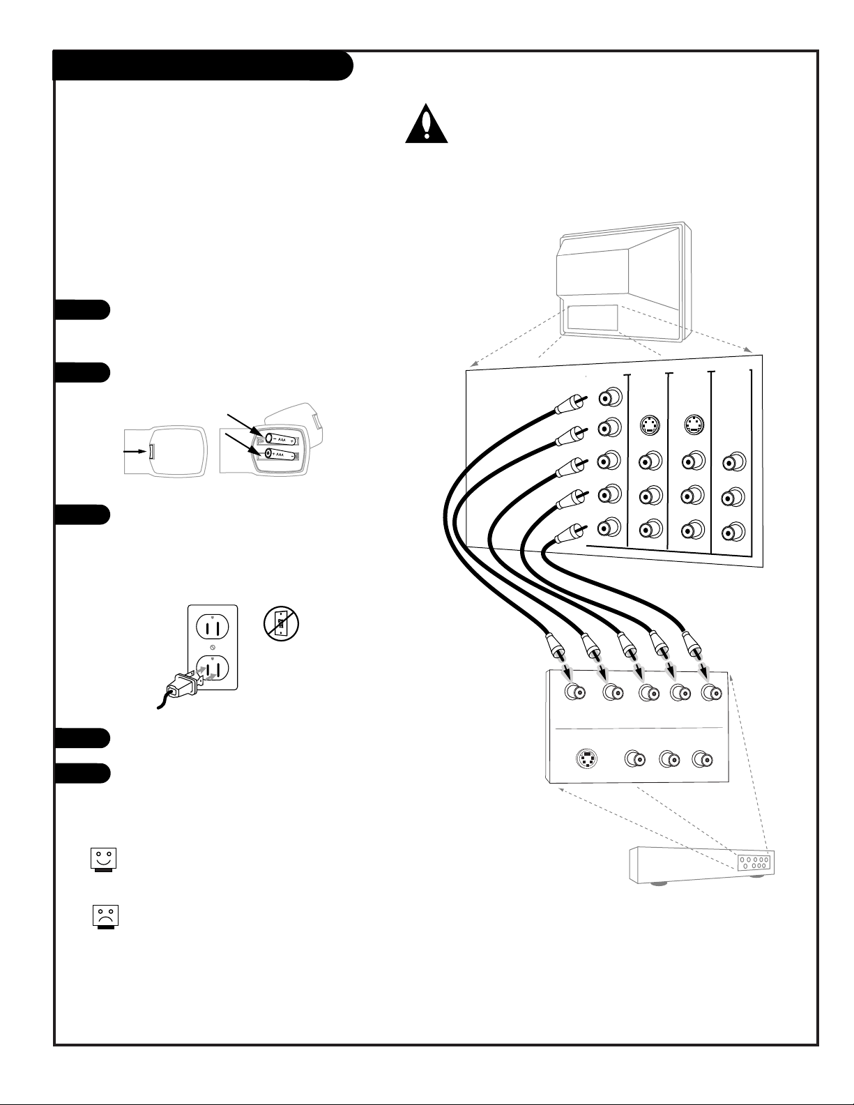
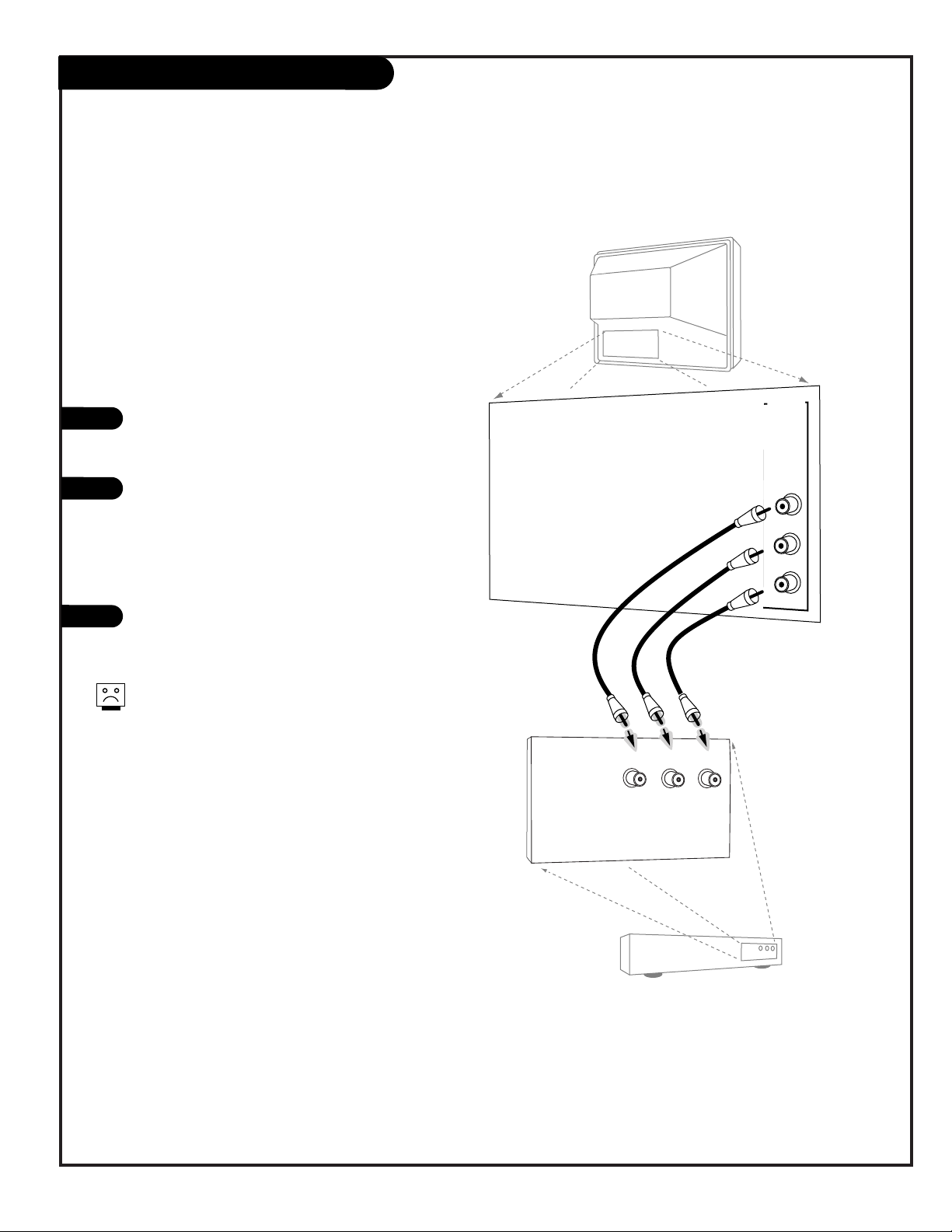
Make the connections as indicated. (Appearance
of components may vary from those in the illustrations.)
Remove the back of the remote and put in two
“AAA” batteries.
Plug in your TV. Your TV is designed to operate
on standard household current, 120-volt 60 Hertz
AC. Do not plug it into an outlet controlled by a
switch. Do not attempt to operate it on DC
power.
Press POWER to turn TV on.
On the remote, press SOURCE repeatedly until
“DVD IN” is displayed. Or use the Source menu to
choose DVD IN.
Hook Up Component Video Equipment
Connecting component video DVD equipment
Component video jacks are sometimes labeled with CR,
C
B, or PB, PR. In this case, connect B to B and the R to
R. The “Y” jack is usually labeled “Y”, connect Y to Y.
DVD IN input does not accept progressive (480p/720p)
or interlaced (1080i) video formats.
1
2
3
120 V AC
60 Hz
4
Back of
Remote
5
DVD IN (480 Interlaced only)
Connect standard component video equipment or a DVD
player here.
DVD Player, 480i
SDTV Set top Box, 480i
The DVD IN Input jacks will only accept an interlaced signal.
Switch your DVD player or set-top box to interlaced.
Page 14
PAGE 14
206-3767
Make the HD connections as indicated.
(Appearance of components may vary from
those in the illustrations.)
Remove the back of the remote and put in
two “AAA” batteries.
Plug in your TV. Your TV is designed to
operate on standard household current,
120-volt 60 Hertz AC. Do not plug it into
an outlet controlled by a switch. Do not
attempt to operate it on DC power.
Press POWER to turn TV on.
On the remote, press SOURCE repeatedly
until “HD-In” is displayed. Or use the
Source menu to choose HD-In.
Hook Up HD Equipment
Connecting high-definition equipment
1
2
3
120 V AC
60 Hz
4
TV Back
Pr
Pb
Y
R
L
P
r
Pb
Y
R
L
R
L
R
L
R
L
RGB
VIDEO 2
IN
VIDEO 1
IN
MONITOR
OUTPUT
AUDIO
AUDIO
AUDIO
AUDIO
AUDIO
VIDEO
VIDEO
VIDEO
S-VIDEO 1
S-VIDEO 2
Set Top Box with
Component Video
HD OUT
Y
Pr
Pb
R
L
S-VIDEO OUT
VIDEO
R-AUDIO
L-/MONO
HD IN
(1080i)
DVD IN
(480i)
Back of
Remote
5
HD IN (1080i Interlaced only)
Connect high-definition component video
equipment here.
HDTV Set top Box, 1080i
HD IN input does not accept progressive (480p/720p)
or interlaced (480i) video formats.
The HD IN Input jacks will only accept a 1080i interlaced
signal. Switch your set-top box to interlaced.
Page 15
PAGE 15
206-3767
Make the Audio/Video Output connections
as indicated. (Appearance of devices may
vary from those in the illustrations.)
Video Output
Use the Video Out jack to connect to an
external video device.
Audio Output
Use the Left and Right Audio Out jacks to
connect an external amplifier and speakers.
(Refer to the Audio Menu on page 31 for
instructions on how to turn the TV’s internal
speakers off and on.)
Select Audio/Video Input on the external
device to see the image and hear the sound
from the TV.
Audio/Video Signal Output
Output to Audio/Video devices
1
2
3
TV Back
Pr
Pb
Y
R
L
P
r
Pb
Y
R
L
R
L
R
L
R
L
RGB
VIDEO 2
IN
VIDEO 1
IN
DVD IN
HD IN
MONITOR
OUTPUT
AUDIO
AUDIO
AUDIO
AUDIO
AUDIO
MONO
MONO
VIDEO
VIDEO
VIDEO
S-VIDEO 1
S-VIDEO 2
Audio/Video Device
VIDEO
IN
R-AUDIO
IN
L-/MONO
IN
If you are watching a DIGITAL CHANNEL or
the source connected to the HD-IN or DVD-IN
jacks, MONITOR OUTPUT is not available.
Page 16

PAGE 16
206-3767
Digital Audio Output
1
2
3
Pr
Pb
Y
R
L
P
r
Pb
Y
R
L
R
L
R
L
R
L
TV Back
VIDEO 2
IN
VIDEO 1
IN
DVD IN
HD IN
MONITOR
OUTPUT
AUDIO
AUDIO
AUDIO
AUDIO
AUDIO
MONO
MONO
VIDEO
VIDEO
VIDEO
S-VIDEO 1
S-VIDEO 2
ANTENNA/
CABLE 1
ANTENNA/
CABLE 2
DIGITAL AUDIO
OUTPUT
OPTICAL
Digital Audio
Optical Input
Digital
Audio Equipment
CALIBRATION
Connect one end of an optical cable to
the TV Digital Audio Optical Output
port.
Connect the other end of the optical
cable to the digital audio optical input
on the audio equipment.
See the external audio equipment
instruction manual for operation.
Send the TV’s audio out to external audio equipment
(stereo system) via the Digital Audio Optical Output port
Caution: Do not look into the
optical output port. Looking at
the laser beam may damage your
vision.
Page 17
206-3767
PAGE 17
Front-Side Panel Controls/Inputs
menu
L-audio-Rvideo
S-video
volume
channel
power
menu
volum
e
channel
power
Typical TV
Front Panel
menu
volume
channel
1
2
Menu Operation
Press MENU to place menus on screen.
Use Channel Up/Down to select menu option.
Use Volume Left/Right to adjust menu option.
Use MENU to remove menus from screen.
TV Operation
Press POWER to turn TV on and off.
Use the CHANNEL Up/Down buttons to select the next
higher/lower channel number
Use the VOLUME Left/Right buttons to adjust the
sound level quieter or louder to your preference.
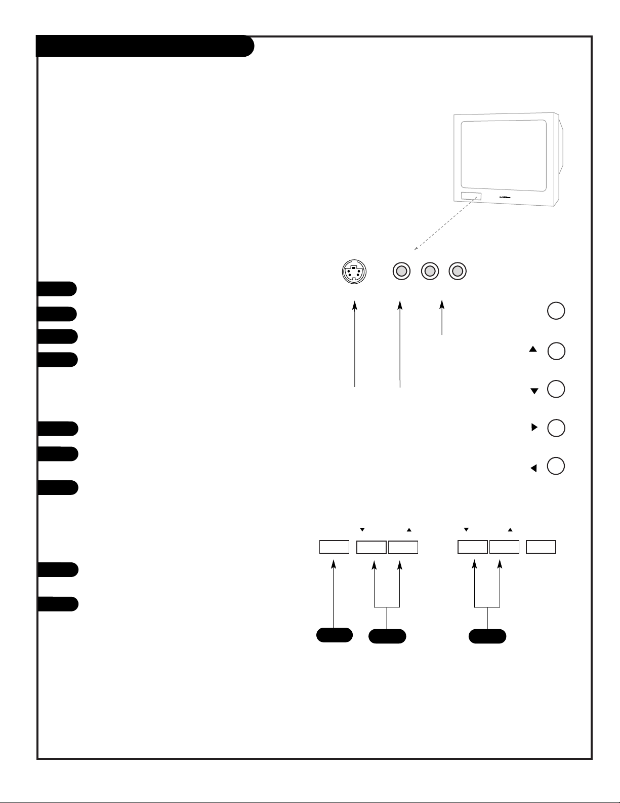
Temporary Connections
Connect your video equipment like a Camcorder to the
Front Video input jacks.
On the remote control, use Source to choose Front
Video, or use the Source menu to choose the Front
Video input source.
Using the front/side panel to operate the TV’s basic
features and to make temporary connections
1
2
Left/Right Audio
Used for stereo
sound from external equipment.
S-Video / Video
Connects the video signals from
external equipment.
Typical Front Panel Controls
Note: Side controls operate the same
as the front controls shown above.
3
3
4
1
2
3
1
2
C34W23
Side Control
Panel
C32V23/C36V23
Front Control Panel
Page 18

PAGE 18
206-3767
EZ Scan (Channel Search)
1
2
3
4
5
Select antenna input,
press
1. TV/DTV Ant only
2. CATV only
3. TV/DTV+CATV
EZ Scan
Ch. Edit
DTV Signal
Tilt
Ch. Label
Input Source
SETUP
VIDEO
AUDIO
LOCK
SPECIAL
TIME
Menu Prev.
Select antenna input,
press
1. TV/DTV Ant only
2. CATV only
3. TV/DTV+CATV
CATV
CADTV
Ant 1
Ant 2
X
Menu Prev.
Select antenna input,
press
1. TV/DTV Ant only
2. CATV only
3. TV/DTV+CATV
CATV
TV/DTV
Ant 1
Ant 2
Menu Prev.
Option 1
Option 2
Option 3
ENTER
ENTER
ENTER
TV/DTV
Ant 1
Ant 2
X
Select cable band,
press
1. Std
2. HRC
3. IRC
ENTER
Mini glossary
TV The antenna device receiving the program signal sent over-the-air.
DTV Digital TV programming sent over-the-air.
CATV Your EZ Scan selection, if you subscribe to a cable service.
CADTV Your EZ Scan selection, if you subscribe to a digital cable service.
*Cable Service Band Note: Select Std=Standard, HRC=HRC Band, or IRC=IRC Band.
For further band information, contact your cable service provider.
Use EZ Scan to automatically find active channels and store them in the TV’s memory
EZ Scan finds active channels being received by the TV tuner.
Cable will not work unless you subscribe to a cable service.
Run EZ Scan again after any Antenna/Cable connection changes.
Press MENU, (if not selected, use the Up/Down arrow to choose
Setup Menu,) then press ENTER or the right arrow button.
Using the Up or Down arrow on the remote control, select EZ Scan
on your screen, then press ENTER or the right arrow button.
Using the Up or Down arrow, select option 1, 2, or 3. (Based on
your connection(s) to Antenna/Cable 1-2.)
Press ENTER to begin the channel search.
Note: Allow EZ Scan to complete the channel search cycle for TV,
CABLE*, DTV, etc.
When the channel search is complete, press MENU repeatedly until
all menus are removed, or press QUIT.
PRG
POWER
CABLE
VCR
AUX
TV
SURF
-
FLASHBK
MUTE
CHANNEL
CHANNEL
VOLUME
VOLUME
12
3
4
56
708
9
MENU
REWIND
F FWD
RECORD
ENTER
SIGNAL
AUDIO
CC
QUIT
SOURCE
PAUSE TIMER
PLAY
STOP
RATIO
VIDEO
1/5
1/2/4
1/2/3
5
1/2
Page 19

206-3767
PAGE 19
PRG
POWER
CABLE
VCR
AUX
TV
SURF
-
FLASHBK
MUTE
CHANNEL
CHANNEL
VOLUME
VOLUME
12
3
4
56
7
0
8
9
MENU
REWIND
F FWD
RECORD
ENTER
SIGNAL
AUDIO
CC
QUIT
SOURCE
PAUSE TIMER
PLAY
STOP
RATIO
VIDEO
TV Mode Remote Key Functions
Note: Pressing TV puts remote into TV operating mode
A quick list of the keys on your remote and what they do in TV mode, see page 48 for remote key
functions in all programmable modes...
PRG (PROGRAM)
Programs your remote to operate
other products.
See page 42.
FLASHBK (FLASHBACK)
Return to the last channel viewed.
POWER
Turns TV On or Off
.
CABLE/VCR/AUX/TV
Selects remote operating mode.
CHANNEL (UP/DOWN)
Selects next available channel.
MUTE
Turns sound Off/On while the picture remains.Press to mute sound,
press again to restore sound.
ENTER
Goes to menu options and shows the
Channel/Time display. Press after
channel numbers for instant selection.
NUMBER KEYPAD
Selects channels directly and enters
numeric values for some options.
MENU
Shows on-screen menus for TV mode.
See page 20.
VIDEO
Selects different picture settings.
remote control part number
MBR4286
(P124-00240)
TIMER
Displays the Sleep Timer Menu.
See “Timer Setup” on page
34 for more information.
VOLUME LEFT/RIGHT
Adjusts the sound levels.
QUIT
Removes on-screen displays.
SOURCE
Switches between watching TV
through available sources.
Keys dedicated to VCR functions
will still operate your VCR while
the remote is in TV mode.
CC (CLOSED CAPTIONING)
Selects closed caption options.
UP/DOWN ARROWS
Up/Down arrows select menu options.
LEFT/RIGHT ARROWS
Left/Right arrows adjust options.
LED INDICATOR LIGHT
Lights when keys are pressed.
SIGNAL
Displays the digital signal
strength. See page 26.
SURF
Press repeatedly to “Surf” through
your favorite channels list.
RATIO
Selects different picture aspect
ratios. See page 35.
AUDIO
Selects available sound options:
Stereo, Mono, SAP. See page 31.
CHANNEL NUMBER DASH “-”
Selects channel numbers with dashes.
Example: 7-0 selects analog channel 7.
7-1, 7-2, etc. select DTV channel 7s.
Page 20

PAGE 20
206-3767
QUIT
MENU
ENTER
Mini glossary
MENU On-screen displays used to set up and operate TV features.
ENTER Action key used to make changes on the menus.
UP/DOWN Menu UP or DOWN directional arrows used to “select” or highlight and choose menu options.
LEFT/RIGHT Menu LEFT or RIGHT directional arrows used to “adjust” some menu settings.
QUIT Exits menus and removes on-screen displays.
Use the
remote to
access the onscreen menus
EZ Picture
Contrast
Brightness
Color
Tint
Sharpness
Color Temp
Z-View
VIDEO
AUDIO
LOCK
SPECIAL
TIME
50
50
50
7 G
50
R
SETUP
EZ Scan
Ch. Edit
DTV Signal
Tilt
Ch. Label
Input Source
SETUP
VIDEO
AUDIO
LOCK
SPECIAL
TIME
Press MENU on the remote control. Use the Up or Down directional arrow to “select” or highlight the name of one of the
six main menus on your screen like the VIDEO menu, then
press ENTER.
Use the Up or Down directional arrow to highlight an option
like the CONTRAST adjustment bar, then press the Right arrow.
You can select other menu options like COLOR TEMP using the
UP or DOWN directional arrows.
Once the option is selected, in this case CONTRAST, use the
RIGHT or LEFT directional arrow to adjust the setting; the larger the number the more contrast, the lower the number, the
less contrast in the picture. Note: Some menu options use a
checkmark to indicate setting, see page 22.
You can adjust the other menu options using the above procedure or if you are done adjusting the menu option settings:
a. Press MENU repeatedly to go back to the main menu.
b. Press QUIT to remove the menus from the TV screen.
On-Screen Menu Operation
1
2
3
4
Additional instructions are usually included on the bottom of the menu
indicating which remote keys to use to move to the right, move to the
left, or return to the previous menu, etc.
Use the number keypad to enter numerical values when required.
2
3
When selected, values change
to a gold color
Main TV Features Menu
Video Menu
1/4
3
2
4
1
Page 21

PAGE 21
206-3767
Input Source Selection Options
1
Choose the connected
source you want to see
and hear on your TV
Press SOURCE repeatedly to choose from the available
input viewing sources.
Analog: Antenna/Cable1 -2 on TV back near Jackpack,
Over-the-Air Antenna or Cable service signal source.
Video 1 In: on TV back Jackpack,
Set of Composite Audio/Video Input jacks.
S-Video Input jack use with Video 1 Audio Input jacks.
Video 2 In: on TV back Jackpack,
Set of Composite Audio/Video Input jacks.
S-Video Input jack use with Video 2 Audio Input jacks.
F Video In: on TV front Jackpack,
Set of Composite Audio/Video Input jacks.
F S-Video In: on TV front Jackpack,
S-Video Input jack use with front Audio Input jacks.
DVD IN: on TV back Jackpack, 480i,
Set of Component Audio/Video Input jacks.
HD In: on TV back Jackpack,
Set of component Audio/Video Input jacks at 1080i.
TV Back
Pr
Pb
Y
R
L
P
r
Pb
Y
R
L
R
L
R
L
R
L
VIDEO 2
IN
VIDEO 1
IN
MONITOR
OUTPUT
AUDIO
AUDIO
AUDIO
AUDIO
AUDIO
VIDEO
VIDEO
VIDEO
S-VIDEO 1
S-VIDEO 2
ANTENNA/
CABLE 1
ANTENNA
2
DIGITAL AUDIO
OUTPUT
OPTICAL
L Audio RVideo
S-Video
HD IN
(1080i)
DVD IN
(480i)
CALIBRATION
AUDIO/VIDEO OUT
VIDEO
R -AUDIO-L
OUT
S-VIDEO
R -AUDIO-L
AUDIO/VIDEO OUT
R -AUDIO-L
AUDIO/VIDEO OUT
VIDEO
R -AUDIO-L
COMPONENT VIDEO
R -AUDIO-L
Camcorder
VCR
S-Video
Audio/Video
DVD
Component Video
Pb
Y Pr
VIDEO
COMPONENT VIDEO
R -AUDIO-L
Y / U / V 1080i
Pb
Y Pr
Typical Viewing Sources
The source equipment you intend to view should be turned on.
Page 22

PAGE 22
206-3767
On-Screen Menus Overview
EZ Scan
Ch. Edit
DTV Signal
Tilt
Ch. Label
Input Source
SETUP
VIDEO
AUDIO
LOCK
SPECIAL
TIME
EZ Picture
Contrast
Brightness
Color
Tint
Sharpness
Color Temp
Z-View
VIDEO
AUDIO
LOCK
SPECIAL
TIME
50
50
50
7 G
50
R
SETUP
Audio Mode
EZ Soundrite
EZ Sound
Balance
Treble
Bass
Speakers
Front Surround
VIDEO
AUDIO
LOCK
SPECIAL
TIME
0
50
50
Menu Prev.
Adjust
SETUP
Select antenna input,
press
1. TV/DTV Ant only
2. CATV only
3. TV/DTV+CATV
Menu Prev.
ENTER
TV/DTV
Ant 1
Ant 2
X
Descriptions of the menus and displays
Using MENU, the Up/Down arrows, and the ENTER key and the other keys indicated on
the remote, the user can access the menus and displays described below.
ON-SCREEN MENUS
SETUP pages 18/25 - 29
Sets the TV up and adjusts the basic features.
EZ Scan page 18
Automatically finds and stores all available channels in
your viewing area; tune in those channels using Channel
Up/Down.
Ch. Edit page 25
Choose which channels will appear when using Channel
Up/Down. Adds favorite channels to Surf channel list.
DTV Signal page 26
Shows the strength of the DTV signal being received.
Tilt page 27
If needed, adjusts the picture by tilting it to fit screen.
Ch. Label page 28
Choose a network symbol to identify the channel.
Input Source page 29
Chooses the input source for the picture and sound.
VIDEO page 30
Adjusts the picture appearance to your preference.
Your options are:
EZ Picture, Contrast, Brightness, Color, Tint, Sharpness,
Color Temperature, Z-View.
AUDIO page 31
Customizes the sound to suit your room and taste.
Your options are:
Audio Mode, EZ Soundrite, EZ Sound, Balance, Treble,
Bass, Speakers, Front Surround.
Page 23

PAGE 23
206-3767
On-Screen Menus/Displays Overview
TIME pages 32 - 34
Sets the TVs internal clock and TV turn on/off functions.
Clock page 32
Sets the current time on the TV.
Off Timer page 33
Sets the time the TV will turn off automatically each day.
On Timer page 33
Sets the time the TV will turn on automatically each day.
Sleep Timer page 34
Sets a time that the TV will automatically turn itself off,
one time.
SPECIAL pages 35 - 38
Goes beyond basics and customizes your TV’s features.
Your options are:
Aspect Ratio page 35
Chooses the correct picture format for the video source.
Analog Caption page 36
Chooses a captioning or text option.
Language page 37
Chooses the language you want the on-screen menus to
appear in: English, Spanish, French.
EZ Demo page 38
On/Off. Demonstrates the on-screen menus that control
the TV’s setup and operational features.
LOCK SYSTEM pages 39 - 40 - 41
Allows parents to block programming based on the program’s content rating, A/V source, or block channel(s).
OTHER ON-SCREEN DISPLAYS (See pages indicated.)
• Mute 24
• Volume Display 24
• Channel/Time 23
• Sleep Timer 24
• Captions/Text 23
Clock
Off Timer
On Timer
Sleep Timer
VIDEO
AUDIO
LOCK
SPECIAL
TIME
Type Manual
Menu Prev.
Year 2002
Date 10 / 23
Time 11 : 25 AM
SETUP
Aspect Ratio
Analog Caption
Language
EZ Demo
VIDEO
AUDIO
LOCK
SPECIAL
TIME
Menu Prev.
English
Spanish
French
SETUP
Lock System
Set Password
Select Country
Block Ch.
Movie Rating
TV Rating-Children
TV Rating-General
Aux. Block
VIDEO
AUDIO
LOCK
SPECIAL
TIME
Menu Prev.
On
Off
SETUP
TV 7-0 XYZ
STEREO
Mute
Analog
PM 2:35
Channel/Time Display
Analog Captions: CC1
Closed Captions menu display
Page 24

206-3767
PAGE 24
Other Functions & On-Screen Displays
On-screen displays reveal the current status of
your Entertainment Machine
C
B
A
B
C
D
E
Mute Display
Press MUTE to remove the sound.
Press MUTE again to restore the sound.
Volume Display
Press the VOLUME +/- key on the remote control to see
the sound level status display.
Channel/Time Display
Press ENTER on the remote control to
view the Channel/Time/incoming
audio signal, and channel label display.
Remove On-Screen Displays and Menus Instantly
Press QUIT to remove displays and menus and return to TV
viewing, or wait a few moments and the displays and
menus will automatically disappear from the screen.
Sleep Timer Display
Sleep Timer Status Display.
E
A
“Surf” Channels are typically your favorite channels that you tune
to and watch frequently.
TV 7-0
STEREO
XYZ
D
Mute
8
Sleep Time: Off
PRG
CABLE
VCR
SURF
FLASHBK
CHANNEL
VOLUME
CHANNEL
12
4
7
0
MENU
RATIO
SIGNAL
AUDIO
RECORD
PAUSE TIMER
POWER
TV
AUX
MUTE
VOLUME
3
56
8
9
-
ENTER
VIDEO
QUIT
CC
SOURCE
REWIND
PLAY
STOP
F FWD
Page 25

PAGE 25
206-3767
Mini glossary
ADD Include a new channel to the channel list that you scroll through
using Channel Up/Down.
DELETE Remove a channel that you don't watch from the channel list that
you scroll through using Channel Up/Down.
SURF Adds a favorite channel to the Surf channel list. Press SURF
repeatedly, channels you specified as Surf channels will be the
only ones to appear. Use Channel Up/Down to return to and scroll
the normal channels list.
Channel Edit Add/Delete/Surf Setup
1
2
3
4
5
Selection ( or )
leads you to the
channel edit screen.
EZ Scan
Ch. Edit
DTV Signal
Tilt
Ch. Label
Input Source
SETUP
VIDEO
AUDIO
LOCK
SPECIAL
TIME
Menu Prev.
ENTER
Customize your channel selection list: Add
Channels, Delete channels you don’t watch,
Create a favorite channels list to “Surf” - press SURF repeatedly to scroll your Surf channels
Press MENU, use the Up/Down arrow to select the SETUP menu,
then press ENTER or the right arrow.
Use the Up/Down arrow to highlight the Ch. Edit option, then
press ENTER or the right arrow.
Use the Up/Down/Left/Right arrows to highlight and select a
channel. (Use Channel Up/Down to show next channel group.)
Press ENTER repeatedly to ADD to or, DELETE the channel from
the channel scan. To add the selected channel to the Surf list,
press SURF. To go to the next group of channels use CHANNEL
Page Up/Page Down.
Use MENU to go back to the SETUP menu. Press QUIT to
remove menu when finished or go to another channel to edit
and repeat from Step 3.
If you’ve deleted a channel, it isn’t gone for good. Just select it using
the NUMBER keypad on the remote, or add it later.
PRG
POWER
CABLE
VCR
AUX
TV
SURF
-
FLASHBK
MUTE
CHANNEL
CHANNEL
VOLUME
VOLUME
12
3
4
56
708
9
MENU
REWIND
F FWD
RECORD
ENTER
SIGNAL
AUDIO
CC
QUIT
SOURCE
PAUSE TIMER
PLAY
STOP
RATIO
VIDEO
1/2/3
5
1/5
1/2/4
4
Page 26

206-3767
PAGE 26
Press MENU to show the menus on-screen.
Use the Up/Down arrow to select the SETUP MENU, then press
ENTER.
Use the Up/Down arrow to select the DTV Signal option. (Use
MENU to go backward as needed.)
View the on-screen signal strength monitor to see the quality of the
signal being received.
Press QUIT to remove menus and return to TV viewing.
Go to the DTV
Signal option
to see the
strength of
the DTV signal
being received
DTV Input Signal Menu
1
2
3
EZ Scan
Ch. Edit
DTV Signal
Tilt
Ch. Label
Input Source
SETUP
VIDEO
AUDIO
LOCK
SPECIAL
TIME
Bad Normal Good
EZ Scan
Ch. Edit
DTV Signal
Tilt
Ch. Label
Input Source
SETUP
VIDEO
AUDIO
LOCK
SPECIAL
TIME
Menu Prev.
4
DTV Signal option is only accessible on the Setup menu if the source is DTV.
Press SIGNAL on the remote control to show signal strength.
5
PRG
POWER
CABLE
VCR
AUX
TV
SURF
-
FLASHBK
MUTE
CHANNEL
CHANNEL
VOLUME
VOLUME
12
3
4
56
708
9
MENU
REWIND
F FWD
RECORD
ENTER
SIGNAL
AUDIO
CC
QUIT
SOURCE
PAUSE TIMER
PLAY
STOP
RATIO
VIDEO
2/3
5
1
2/3
Page 27

PAGE 27
206-3767
Tilt Menu
Use the Tilt
option to correct the picture
angle, if necessary
Press MENU to show the menus on-screen.
Use the Up/Down arrow to select the SETUP MENU, then press
ENTER or the right arrow button.
Use the Up/Down arrow to select the Tilt option.
Use the Left/Right arrow to adjust the Tilt of the picture image
to your preference.
Press QUIT to remove menus and return to TV viewing.
1
2
3
4
Menu Prev.
EZ Scan
Ch. Edit
DTV Signal
Tilt
Ch. Label
Input Source
SETUP
VIDEO
AUDIO
LOCK
SPECIAL
TIME
EZ Scan
Ch. Edit
DTV Signal
Tilt
Ch. Label
Input Source
SETUP
VIDEO
AUDIO
LOCK
SPECIAL
TIME
0
Change ( or ) value
of tilt.
5
PRG
POWER
CABLE
VCR
AUX
TV
SURF
-
FLASHBK
MUTE
CHANNEL
CHANNEL
VOLUME
VOLUME
12
3
4
56
708
9
MENU
REWIND
F FWD
RECORD
ENTER
SIGNAL
AUDIO
CC
QUIT
SOURCE
PAUSE TIMER
PLAY
STOP
RATIO
VIDEO
2/3/4
5
1
1/2/4
The tilt angle you set will be retained in the TV’s memory. When
the TV is turned on, the tilt angle last set will be used.
Page 28

PAGE 28
206-3767
Channel Label Menu
1
Label the
channels with
their logos for
easier identification when
tuning
EZ Scan
Ch. Edit
DTV Signal
Tilt
Ch. Label
Input Source
SETUP
VIDEO
AUDIO
LOCK
SPECIAL
TIME
Selection ( or )
leads you to the
channel logo screen.
EZ Scan
Ch. Edit
DTV Signal
Tilt
Ch. Label
Input Source
SETUP
VIDEO
AUDIO
LOCK
SPECIAL
TIME
Menu Prev.
ENTER
Press MENU, use the Up/Down arrow to select the SETUP menu,
then press the right arrow or ENTER.
Use the Up/Down arrow to select the Ch. Label option on your
screen, then press the right arrow or ENTER.
Tune to the channel you want to label with a logo, using the
Channel Up/Down arrows.
Use the Up/Down/Left/Right arrows to select a logo for the channel, then press ENTER. The logo appears above the channel picture
on the menu.
Tune to another channel to continue labeling or press QUIT to
remove menu and to return to TV viewing.
2
3
4
5
2/4
5
1
2/3/4
When you press ENTER, the label you have chosen will appear in the
channel/time display.
When you scroll through the channels, any label set for a channel will
appear in the channel/time display.
3
TV 7-0
STEREO
XYZ
PRG
CABLE
VCR
SURF
FLASHBK
CHANNEL
VOLUME
CHANNEL
12
4
7
0
MENU
RATIO
SIGNAL
AUDIO
RECORD
PAUSE TIMER
REWIND
POWER
TV
AUX
MUTE
VOLUME
3
56
8
9
-
ENTER
VIDEO
QUIT
CC
SOURCE
PLAY
F FWD
STOP
Page 29

PAGE 29
206-3767
Using SOURCE to Choose Viewing Sources
Press SOURCE repeatedly to scroll through the available sources:
Analog, DTV, Video 1, Video 2, F Video, DVD, and HD.
Selecting Input Source using the Setup Menu
Press MENU to show the menus on-screen.
Use the Up/Down arrow to select the SETUP MENU option, then
press ENTER.
Use the Up/Down arrow to select the Input Source option, then
press ENTER. (Use MENU to go backward as needed.)
Use the Up/Down arrow to move the checkmark and select Analog,
or one of the other available sources.
After you have selected a viewing source, press QUIT to remove the
menu and return to TV viewing.
Choose the
picture and
sound you
want to see
and hear for
the main
screen
Selecting Input Sources
A
1
2
3
Analog
DTV
Video 1
Video 2
Front Video
DVD In
HD In
Menu Prev.
EZ Scan
Ch. Edit
DTV Signal
Tilt
Ch. Label
Input Source
SETUP
VIDEO
AUDIO
LOCK
SPECIAL
TIME
EZ Scan
Ch. Edit
DTV Signal
Tilt
Ch. Label
Input Source
SETUP
VIDEO
AUDIO
LOCK
SPECIAL
TIME
4
If S-Video sources are connected, they will appear on the Source menu as
Video 1, 2 etc.
Be sure to use the Video menu to change the Aspect Ratio as needed when
using sources which have different picture proportions for the main screen.
5
PRG
POWER
CABLE
VCR
AUX
TV
SURF
-
FLASHBK
MUTE
CHANNEL
CHANNEL
VOLUME
VOLUME
12
3
4
56
708
9
MENU
REWIND
F FWD
RECORD
ENTER
SIGNAL
AUDIO
CC
QUIT
SOURCE
PAUSE TIMER
PLAY
STOP
RATIO
VIDEO
2/3/4
5
1
A
2/3/4
Page 30

PAGE 30
206-3767
Video Menu
Press MENU, use the Up/Down arrow to select the Video menu,
then press ENTER or the Right arrow.
Using the Up/Down arrow on the remote control, choose
Contrast (or another menu option on your screen), then press
the Right arrow twice.
Using the Left/Right arrow, change the Contrast level to your
preference. Use the Up/Down arrow to select other adjustment
bars like Brightness, Color, Tint, and Sharpness.
Press QUIT, to return to TV viewing, or press MENU and repeat
from step two to set the other menu options. Your options are:
• EZ Picture: Choose either Custom, Normal, Digital Preset,
Night Time, Movie, Weak Signal, Video Game, or Sports.
Custom: Allows you to adjust the picture the way you want.
Normal: Resets all the options to their preset values.
Other options adjust the picture to the source’s image.
• Contrast: Adjusts the level of difference between white and
black in the TV picture. The more contrast, the brighter the
picture appears.
• Brightness: Increases or decreases amount of white in the TV
picture.
• Color: Adjusts levels of all colors in the TV picture.
• Tint: Adjusts the relative amounts of red and green colors in
your picture.
• Sharpness: Raises or lowers the definition of the picture. The
lower the level, the softer the image will appear.
• Color Temp: Adjusts levels of all colors in the TV picture; Cool
or Warm.
• Z-View: On, automatically adjusts the picture display for optimum quality: on or off.
1
2
3
4
Choose the NORMAL option in EZ Picture to quickly reset the Video Menu
options to their original pre-set values, or use your own settings with CUSTOM.
Use the Video
menu to customize the
picture appearance
EZ Picture
Contrast
Brightness
Color
Tint
Sharpness
Color Temp
Z-View
VIDEO
AUDIO
LOCK
SPECIAL
TIME
50
50
50
7 G
50
R
SETUP
EZ Scan
Ch. Edit
DTV Signal
Tilt
Ch. Label
Input Source
SETUP
VIDEO
AUDIO
LOCK
SPECIAL
TIME
PRG
POWER
CABLE
VCR
AUX
TV
SURF
-
FLASHBK
MUTE
CHANNEL
CHANNEL
VOLUME
VOLUME
12
3
4
56
708
9
MENU
REWIND
F FWD
RECORD
ENTER
SIGNAL
AUDIO
CC
QUIT
SOURCE
PAUSE TIMER
PLAY
STOP
RATIO
VIDEO
2/3/4
4
1/4
1/2/4
Page 31

PAGE 31
206-3767
Mini glossary
STEREO SOUND Stereo (stereophonic) sound refers to audio that’s
divided into right and left sides.
MONO SOUND Mono (monaural) sound is one channel of sound. For
more than one speaker, all the speakers play the
same audio.
2nd Audio/SAP Second audio program provided by some
broadcasters; usually a different language.
Front Surround Front Surround is a stereo effect.
Adjust the
sound to your
preference and
set up the
audio features
1
2
3
4
Not all programming is broadcast in stereo sound or has 2nd Audio SAP.
Audio Menu
Press MENU, use the Up/Down arrow to select the Audio menu,
then press ENTER or the Right arrow button.
Using the Up/Down arrow on the remote control, highlight the
audio option you want to adjust, then press the Right arrow.
Using the Left/Right arrow, change the Audio option level to your
preference.
Press QUIT, to return to TV viewing, or press MENU and repeat from
step two to set the other menu options. Your options are:
• Audio Mode: Choose from Stereo sound, Mono sound, or 2nd
Audio/SAP.
• EZ SoundRite: Turns the uniform volume level on or off.
• EZ Sound: Use one of the five factory audio presets: Normal,
Stadium, News, Music, Theater, or your own “Custom” settings.
• Balance: Allows you to put the sound more to the left or right
channel.
• Treble: Increases/decreases higher-end sounds.
• Bass: Increases/decreases lower-end sounds.
• Speakers: Turns the TV speakers on or off.
• Front Surround: Turns front surround sound on or off.
Audio Mode
EZ Soundrite
EZ Sound
Balance
Treble
Bass
Speakers
Front Surround
VIDEO
AUDIO
LOCK
SPECIAL
TIME
0
50
50
Menu Prev.
Adjust
SETUP
EZ Scan
Ch. Edit
DTV Signal
Tilt
Ch. Label
Input Source
SETUP
VIDEO
AUDIO
LOCK
SPECIAL
TIME
PRG
POWER
CABLE
VCR
AUX
TV
SURF
-
FLASHBK
MUTE
CHANNEL
CHANNEL
VOLUME
VOLUME
12
3
4
56
708
9
MENU
REWIND
F FWD
RECORD
ENTER
SIGNAL
AUDIO
CC
QUIT
SOURCE
PAUSE TIMER
PLAY
STOP
RATIO
VIDEO
1/2/3
4
1/4
1/2/3
Page 32

PAGE 32
206-3767
In the Time menu with the Clock option highlighted, press ENTER
or the right arrow to go to the Clock Menu.
Use the Left/Right arrows to move through the menu and the
Up/Down arrows to set the clock as indicated on the menu.
Clock Menu Options
Press QUIT to return to TV viewing, or press MENU to return to
the previous menu.
The On/Off timers will not work until the Clock on your television has been set.
You need to set the current time manually the first time the TV is connected to
power. This will activate the clock.
Set the Clock
1
2
3
Clock
Off Timer
On Timer
Sleep Timer
VIDEO
AUDIO
LOCK
SPECIAL
TIME
Type Manual
Menu Prev.
Year 2002
Date 10 / 25
Time 11 : 25 AM
SETUP
Clock
Off Timer
On Timer
Sleep Timer
VIDEO
AUDIO
LOCK
SPECIAL
TIME
SETUP
Manual Mode
User sets the Clock options.
• Year: Set the current year.
• Date: Set the Month and Date.
• Time: Set the Hours, Minutes,
and AM or PM.
Auto Mode
TV sets the clock, but the user
can enter the menu and set the
appropriate info:
• PBS Channel: Set the channel
number of your PBS station to
receive time from PBS signal.
• Time Zone: Set your time zone:
Auto, Eastern, Central,
Mountain, Pacific., Alaska,
Hawaii, New F land, Atlantic.
• Daylight Savings: Turn Off or On.
Mini glossary
TIME A four-number figure broken down into hours and minutes; first two
numbers are hours, last two numbers are minutes.
HOURS First two numbers entered when setting the clock.
MINUTES Second two numbers entered when setting the clock.
Set the clock
yourself or
have the TV do
it for you
PRG
POWER
CABLE
VCR
AUX
TV
SURF
-
FLASHBK
MUTE
CHANNEL
CHANNEL
VOLUME
VOLUME
12
3
4
56
708
9
MENU
REWIND
F FWD
RECORD
ENTER
SIGNAL
AUDIO
CC
QUIT
SOURCE
PAUSE TIMER
PLAY
STOP
RATIO
VIDEO
1/2
3
1/3
1
Page 33

PAGE 33
206-3767
On/Off Timer Menus
Clock
Off Timer
On Timer
Sleep Timer
VIDEO
AUDIO
LOCK
SPECIAL
TIME
Menu Prev.
Time 11 : 00 PM
SETUP
Clock
Off Timer
On Timer
Sleep Timer
VIDEO
AUDIO
LOCK
SPECIAL
TIME
SETUP
Off
On
Setting the TV Turn Off Time
With the Time menu selected, use the Up/Down arrows to choose
the Off Timer option, then press ENTER or the Right arrow button.
Use the Left/Right arrows to move through the menu and the
Up/Down arrows to set the Off Timer options, as indicated on the
menu.
Setting the TV Turn On Time
With the Time menu selected, use the Up/Down arrows to choose
the On Timer option, then press ENTER or the Right arrow button.
Use the Left/Right arrows to move through the menu and the
Up/Down arrows to set the On Timer options, as indicated on the
menu. Set the TV turn on time, channel, and volume level.
Press QUIT to return to TV viewing, or press MENU to return to
the previous menu.
Use the On/Off
Timers to turn
the TV on and
off each day at
the on and off
specified times
1
2
1
2
3
PRG
POWER
CABLE
VCR
AUX
TV
SURF
-
FLASHBK
MUTE
CHANNEL
CHANNEL
VOLUME
VOLUME
12
3
4
56
708
9
MENU
REWIND
F FWD
RECORD
ENTER
SIGNAL
AUDIO
CC
QUIT
SOURCE
PAUSE TIMER
PLAY
STOP
RATIO
VIDEO
1/2
3
1/3
1
Page 34

PRG
POWER
CABLE
VCR
AUX
TV
SURF
-
FLASHBK
MUTE
CHANNEL
CHANNEL
VOLUME
VOLUME
12
3
4
56
708
9
MENU
REWIND
F FWD
RECORD
ENTER
SIGNAL
AUDIO
CC
QUIT
SOURCE
PAUSE TIMER
PLAY
STOP
RATIO
VIDEO
PAGE 34
206-3767
Sleep Timer Menu
A
1
Clock
Off Timer
On Timer
Sleep Timer
VIDEO
AUDIO
LOCK
SPECIAL
TIME
Menu Prev.
SETUP
Clock
Off Timer
On Timer
Sleep Timer
VIDEO
AUDIO
LOCK
SPECIAL
TIME
SETUP
Off
10 min
20 min
30 min
60 min
90 min
120 min
180 min
240 min
Sleep Timer
Use the TIMER button to choose a preset time from 10 minutes to
4 hours for the TV to automatically turn itself off.
Using the Sleep Timer Menu
Selecting Sleep Timer Menu
With the Time menu selected, use the Up/Down arrows to choose
the Sleep Timer option, then press ENTER or the right arrow button.
Use the Up/Down arrows to select a preset TV turn-off time from
the preset options listed, press ENTER.
Press QUIT to remove the menu and return to TV viewing.
Set the Sleep
Timer to automatically turn
the TV off,
after the preset time has
expired
2
3
A
1/2
3
1
1/2
Page 35

PAGE 35
206-3767
Aspect Ratio Menu
Direct Entry Method: RATIO Key
Press RATIO repeatedly to select available aspect ratios for viewing
source.
Using the Special Menu Option Method
With the Special menu selected, press ENTER or the Right arrow
button.
Use the Up/Down arrow to select the Aspect Ratio option, then
press ENTER or the Right arrow button.
Using the Up/Down arrow, choose the correct Aspect Ratio on
the menu, then press ENTER.
Your options are:
• Set By Program: Selects the proper picture proportion to
match the source’s image; 16:9, 4:3.
• 16:9: Selects the proper picture proportion to match the 16:9
source’s image.
• 4:3: Selects the proper picture proportion to match the 4:3
source’s image.
Press QUIT, to return to TV viewing.
1
2
3
Change the picture aspect
ratio to the format required by
the selected
source
Aspect Ratio
Analog Caption
Language
EZ Demo
VIDEO
AUDIO
LOCK
SPECIAL
TIME
Menu Prev.
Set By Program
16:9
4:3
SETUP
EZ Scan
Ch. Edit
DTV Signal
Tilt
Ch. Label
Input Source
SETUP
VIDEO
AUDIO
LOCK
SPECIAL
TIME
4
Mini glossary
4:3 Standard 4 x 3 almost square-like picture proportion used for most TV formats.
16:9 Wider than normal picture format used for HD sources that produce more movie
theater-like images.
PRG
POWER
CABLE
VCR
AUX
TV
SURF
-
FLASHBK
MUTE
CHANNEL
CHANNEL
VOLUME
VOLUME
12
3
4
56
708
9
MENU
REWIND
F FWD
RECORD
ENTER
SIGNAL
AUDIO
CC
QUIT
SOURCE
PAUSE TIMER
PLAY
STOP
RATIO
VIDEO
1/2/3
4
1/2/3
If the Aspect Ratio option is not selectable on the menu, then the picture
source is correct and no other options are available.
A
A
For Model No. C34W23, Aspect Ratio will be Normal, Wide, or Zoom. As a
result, Set by Program, 16:9, and 4:3 are not available.
Page 36

PAGE 36
206-3767
PRG
POWER
CABLE
VCR
AUX
TV
SURF
-
FLASHBK
MUTE
CHANNEL
CHANNEL
VOLUME
VOLUME
12
3
4
56
708
9
MENU
REWIND
F FWD
RECORD
ENTER
SIGNAL
AUDIO
CC
QUIT
SOURCE
PAUSE TIMER
PLAY
STOP
RATIO
VIDEO
1
2
3
4
Analog Caption Menu
Aspect Ratio
Analog Caption
Language
EZ Demo
VIDEO
AUDIO
LOCK
SPECIAL
TIME
Menu Prev.
Off
CC1
CC2
CC3
CC4
Text 1
Text 2
Text 3
Text 4
SETUP
EZ Scan
Ch. Edit
DTV Signal
Tilt
Ch. Label
Input Source
SETUP
VIDEO
AUDIO
LOCK
SPECIAL
TIME
Choose a Closed
Captions or Text
option or turn the
feature off
Standard closed captioning is available using the Caption 1 option.
Not all programming has closed captioning or text available; even though
Captions 1, 2, 3, 4, and Text 1, 2, 3, 4 are available to broadcasters.
Press MENU, use the Up/Down arrow to select the Special menu,
then press ENTER or the Right arrow button.
Use the Up/Down arrow to choose Analog Caption, then press
ENTER or the Right arrow button.
Use the Up/Down arrow to select an option from the Analog
Caption menu (Caption/Text):
Off, Caption 1, Caption 2, Caption 3, Caption 4, Text 1, Text 2,
Text 3, or Text 4; so that the option will appear when the TV is
tuned to a program that has Closed Captions or Text.
Press QUIT to remove menu and return to TV viewing.
Analog Caption (Caption/Text) allows your TV to receive various closed
caption and text options if provided by broadcasters.
Availability and functionality of Caption/Text is determined only by the
broadcaster and may not be available on a given program. Standard captions are usually on Caption1, standard text is usually on Text 1.
Mini glossary
CAPTIONS The term for the words that scroll across the bottom of the TV screen; usually
the audio portion of the program provided for the hearing impaired.
TEXT The term for the words that appear in a large black frame and almost cover the
entire screen; usually messages provided by the broadcaster.
1/2/3
4
1/4
1/2/3
Page 37

PAGE 37
206-3767
Language Menu
Aspect Ratio
Analog Caption
Language
EZ Demo
VIDEO
AUDIO
LOCK
SPECIAL
TIME
Menu Prev.
English
Spanish
French
SETUP
EZ Scan
Ch. Edit
DTV Signal
Tilt
Ch. Label
Input Source
SETUP
VIDEO
AUDIO
LOCK
SPECIAL
TIME
1
2
3
4
Press MENU, use the Up/Down arrow to select the Special menu, then
press ENTER or the Right arrow button.
Use the Up/Down arrow to select the Menu Language option on your
screen, then press ENTER or the Right arrow button.
Use the Up/Down arrow to choose any of the following options:
English, Spanish, or French, then press ENTER.
Press QUIT to remove menu and to return to TV viewing.
Choose the
language you
want the onscreen menus
to appear in
PRG
POWER
CABLE
VCR
AUX
TV
SURF
-
FLASHBK
MUTE
CHANNEL
CHANNEL
VOLUME
VOLUME
12
3
4
56
708
9
MENU
REWIND
F FWD
RECORD
ENTER
SIGNAL
AUDIO
CC
QUIT
SOURCE
PAUSE TIMER
PLAY
STOP
RATIO
VIDEO
1/2/3
4
1
1/2/3
Page 38

PAGE 38
206-3767
EZ Demo Menu
Mini glossary
EZ DEMO Feature provides an automatic demonstration of the
on-screen menus available on your TV.
View and learn what features are available to you as EZ
Demo cycles through the on-screen menus.
Your TV can
display the
menus
available
Press MENU and use Up/Down arrow to select the SPECIAL
menu, then press ENTER or the Right arrow button.
Use the Up/Down arrow to select the EZ DEMO option.
When you press ENTER or the Right arrow button, EZ Demo
will start and continue to run.
Press QUIT to stop EZ Demo, remove menu and return to TV
viewing.
1
2
3
4
PRG
POWER
CABLE
VCR
AUX
TV
SURF
-
FLASHBK
MUTE
CHANNEL
CHANNEL
VOLUME
VOLUME
12
3
4
56
708
9
MENU
REWIND
F FWD
RECORD
ENTER
SIGNAL
AUDIO
CC
QUIT
SOURCE
PAUSE TIMER
PLAY
STOP
RATIO
VIDEO
1/2
4
1
1/3
SETUP
VIDEO
AUDIO
TIME
SPECIAL
LOCK
EZ Scan
Ch. Edit
DTV Signal
Tilt
Ch. Label
Input Source
SETUP
VIDEO
AUDIO
TIME
SPECIAL
LOCK
Aspect Ratio
Analog Caption
Language
EZ Demo
Menu Prev.
Selection ( or )
ENTER
leads you to the
EZ Demo.
Page 39

PAGE 39
206-3767
Lock (Parental Control) Overview
If used, this optional feature can “block” undesirable programming from appearing on the TV.
Note: Lock, is also known and referred to in the text as Parental Control. To block specific source inputs,
use the AUX. Block options. Lock options are available by country: USA and Canada. Lock options are
also available with TV Ratings for English and TV Ratings for French. Block individual channels if desired.
Overview
To insure complete coverage for all TV programs, (movies and regular TV shows) choose a rating for MPAA, from the selections AND choose ratings from the TV Parental Guidelines Rating System, using the Age Block option for General
Audiences, and for Children. In addition to those, you may wish to add additional restrictions from viewing certain channels. See the Lock menu, and submenus example on the following pages.
Things to Consider before Setting Up Lock (Parental Control)
• Determine which rating you consider acceptable to the viewer. (For example, if you choose TV-PG, all more restrictive
ratings will be automatically blocked; the viewer will not be able to see: TV-PG, TV-14, or TV-MA rated programming.)
• Do you want to block the auxiliary video sources? (Blocks the signal sent by the equipment, such as a VCR, connected
to the TV Audio/Video input jacks; in the Aux. Block option.) Or leave unblocked, but choose allowable ratings.
• In the TV Rating-General option, block program “Content” based on individual parameters such as: Age, Dialog,
Language, Sex, Violence, or in the TV Rating-Children option: Fantasy Violence.
• Select a secret password; in the Set Password option. Use the number keys on the remote. Don’t forget the password, it
is the only way you can access the Lock menu and change rating selections, or turn Lock off.
• Do you want Lock to be active all the time? If not, you can turn it on or off; with the Lock On/Off option.
You can set different Parental Control viewing restrictions for general audiences and for children - - both can
be active at the same time
.
Simply specifying one content block such as Sex, will not
automatically block another content in the programs
from appearing.
Even if you choose to leave the Aux source inputs unblocked,
the ratings you specify will automatically restrict the programming that appears from the video sources.
You cannot disable Lock by disconnecting the TV from power.
Lock will automatically reset if power is disconnected.
Lock/Parental Control offers the user a wide variety of options and settings that restrict or “block” the programming that
can appear on the TV. Parental control allows the user the capability of defining which program rating they consider
acceptable, to the younger or more sensitive viewer. It can be preset and turned either on or off by the user who specifies the secret 4-number code, the password. General audience and children viewer blocks should both be programmed
into the TV’s memory. Viewer ratings are specified for both TV and the motion picture industry; both rating systems
should be used, for complete coverage. The ratings are based mainly on children’s ages.
Page 40

PAGE 40
206-3767
Lock Menu
Lock Menu Typical Setup Requirements
As shown above, with the Lock System turned on:
- Set the initial 4-digit password “0-0-0-0” with the number
keypad. After setting the password and confirming it, use the
Up/Down arrow to highlight an option like TV Rating-General,
then press ENTER or the Right arrow.
Navigating Within the Lock Menu
Use the Up/Down/Left/Right arrows to select and adjust or set
the rating for an option. For “Language” for example, use the
“TV-PG” setting. (See the Mini Glossary, Ratings Charts on this
and the next page for rating definitions.) Use MENU to return
to the previous menu.
Activating Your Blocking Scheme
After you have selected and adjusted the Lock menu options to
your preference:
- Set the Lock System option to either On or Off.
After you
have read
the preceding
page, follow
instructions
below to set
up and activate Lock
Lock System
Set Password
Select Country
Block Ch.
Movie Rating
TV Rating-Children
TV Rating-General
Aux. Block
VIDEO
AUDIO
LOCK
SPECIAL
TIME
Menu Prev.
On
Off
SETUP
EZ Scan
Ch. Edit
DTV Signal
Tilt
Ch. Label
Input Source
SETUP
VIDEO
AUDIO
LOCK
SPECIAL
TIME
-
12
3
4
56
7
0
8
9
MENU
ENTER
SIGNAL
AUDIO
CC
QUIT
RATIO
VIDEO
Up/Down
Left/Right
Arrows
Menu
(Previous)
Number
Keypad
Mini glossary
MOTION PICTURE ASSOCIATION OF AMERICA (MPAA) RATING SYSTEM
G General Audiences Content not offensive to most viewers.
PG Parental Guidance Content is such that parents may not want their children to view the program.
Suggested
PG-13 Parental Guidance Program is inappropriate for preteens, with a greater degree of offensive material
Suggested than a PG rated program.
R Restricted viewing Not for children under age 17. Strong elements of sex and/or violence.
NC-17 Restricted Viewing Not for children under age 17 under any circumstances. Strong sexual content.
X Hard Core Films Same as NC-17 rating.
Note: Zenith Electronics Corporation is not liable for any program content that appears when using this rating system; as always, user
discretion is advised.
Enter
(Next)
Page 41

PAGE 41
206-3767
Mini glossary
TV PARENTAL GUIDELINE RATING SYSTEM
TV-G General Audience Considered suitable for all audiences; children may watch unattended.
TV-PG Parental Guidance Suggested Unsuitable for younger children, may contain: Suggestive Dialog, Bad Language, Sex, and Violence Scenes.
TV-14 Parents Strongly Cautioned Unsuitable for children under 14, may contain: Strong Dialog, Bad Language, Sex, and Violence Scenes.
TV-MA Mature Audience Only Adults only, may contain: Strong Dialog, Bad Language, Sex, and Violence Scenes.
CHILDREN’S CLASSIFICATIONS
TV-Y Children Considered suitable for all children under 7 years old.
TV-Y7 Children 7 and over Considered suitable for children over 7, may contain Fantasy Violence Scenes.
Lock System Menu Structure
Lock System menus with various restriction options are shown below
On
Off
New ****
Confirm ****
All Block
G
PG
PG-13
R
NC-17
X
Blocking Off
Age
Fantasy Violence
Lock System
Set Password
Select Country
Block Ch.
Movie Rating
TV Rating-Children
TV Rating-General
Aux. Block
VIDEO
AUDIO
LOCK
SPECIAL
TIME
Menu Prev.
SETUP
EZ Scan
Ch. Edit
DTV Signal
Tilt
Ch. Label
Input Source
SETUP
VIDEO
AUDIO
LOCK
SPECIAL
TIME
USA
Canada
Selection
leads you to the
block channel screen.
Age
Dialog
Language
Sex
Violence
Video 1 Off
Video 2 Off
Front Video Off
DVD In Off
HD In Off
To Submenus
To Submenus
To Submenu
Page 42

PAGE 42
206-3767
Mini glossary
PROGRAMMING Procedure to set up remote to operate other equipment.
PRG Programming mode button.
DEVICE Infra-red remote controllable electronic accessory devices.
Programming the Remote
1
2
3
4
5
6
Set up your remote to operate other brand name devices
PRG
POWER
CABLE
VCR
AUX
TV
SURF
-
FLASHBK
MUTE
CHANNEL
CHANNEL
VOLUME
VOLUME
12
3
4
56
708
9
MENU
REWIND
F FWD
RECORD
ENTER
SIGNAL
AUDIO
CC
QUIT
SOURCE
PAUSE TIMER
PLAY
STOP
RATIO
VIDEO
7
4
6
Programming your Zenith remote may allow you to use
one remote to operate up to 4 different devices, if all
modes are programmed.
Once the device turns off, try the other functions. IF
they do not operate, try another code. Or, see page 45.
Not all devices will operate with your Zenith remote
control.
5
3
Turn on the device you want to program.
On the chart on page 46/47, find the type of device you’re
programming, and then find the brand name. Write down the
three-number code(s).
Press and hold PRG. It’s recessed so it doesn’t get pushed
accidentally. Use a small, blunt object. When the indicator
light turns on, you can release PRG.
Push the button name with the type of device you’re programming: VCR, CABLE, AUX, TV.
Using the NUMBER keypad, enter the three-number code you
found on page 46/47.
Press ENTER to save the code. (The indicator light will flash
2 times, then turn off to indicate the code is valid.)
Point the remote at the device and push POWER. It should
turn off. If not, try the other codes listed and continue from
step three.
Note: To reset remote to factory settings, enter 9-1-1, in
Step 5.
7
Indicator Light
Mode / Product Compatibility
TV VCR CATV AUX
TVs VCRs Cable Boxes, All products on pp 46 - 47
DVDs Satellite Receivers
Page 43

PAGE 43
206-3767
With a small blunt object, press and hold PRG until the LED
indicator light turns on (about 3 seconds), then release PRG.
Press the mode button of the device you want to hear:
CABLE, VCR, AUX, TV.
Press the Vol+ button, the LED will blink.
Press the button of the mode you want the volume to be controlled by: CABLE, VCR, AUX, TV.
Press ENTER to save the code (The indicator light will flash 2
times and then turn off).
For example: If you want the VCR mode to control the volume of
the AUX mode (audio system), press VCR in Step 2 and press
AUX in Step 4. Then, when you press volume in VCR mode, the
device programmed for the AUX mode will respond.
Mini glossary
AMPLIFIER Audio device which sends sound to speakers, like an Audio Tuner, Receiver, or Amplifier.
See Audio Tuners/Amp list on page 47.
CABLE BOX VOLUME Some cable boxes have volume controls.
AUX Auxiliary equipment.
Mode Sound Switch Setup
1
2
3
4
5
If you can’t find the code for your amplifier, use the Auto Search
feature described on page 45.
This feature is typically used to set up the remote to control the sound from an
external audio system, or cable box, without changing modes
Note: Check to make sure the remote operates the device you want to hear. If
not, see the remote programming page.
PRG
POWER
CABLE
VCR
AUX
TV
SURF
-
FLASHBK
MUTE
CHANNEL
CHANNEL
VOLUME
VOLUME
12
3
4
56
708
9
MENU
REWIND
F FWD
RECORD
ENTER
SIGNAL
AUDIO
CC
QUIT
SOURCE
PAUSE TIMER
PLAY
STOP
RATIO
VIDEO
2/4
1
Indicator Light
5
Default Mode Volume Control Setups
Mode Sound controlling mode
TV TV (Controls TV volume.)
VCR TV (Controls TV volume.)
AUX AUX (Controls AUX Volume.)
CABLE CABLE (Controls Cable Volume.)
3
Page 44

PAGE 44
206-3767
Mini glossary
PROGRAMMING Procedure to set up remote to operate other equipment.
PRG Programming mode key.
DEVICE CODE Code to control infra-red remote controllable electronic devices: TVs, VCRs, Cable Boxes, etc.
Verify 3-Digit Code Stored in Mode
1
2
Use the following method described below to find the code number stored in
memory for each remote operating mode: TV, VCR, CABLE, and AUX
PRG
POWER
CABLE
VCR
AUX
TV
SURF
-
FLASHBK
MUTE
CHANNEL
CHANNEL
VOLUME
VOLUME
12
3
4
56
708
9
MENU
REWIND
F FWD
RECORD
ENTER
SIGNAL
AUDIO
CC
QUIT
SOURCE
PAUSE TIMER
PLAY
STOP
RATIO
VIDEO
2
3
Programming your Zenith remote may allow you to use one remote
to work up to 4 different devices, if all modes are programmed.
Not all devices will work with your Zenith remote control.
1
With a small blunt object, press and hold PRG for about three
seconds. When the light turns on, release PRG.
Press the mode button you want the 3-number code for, then
press the TIMER button.
The LED will blink the number of times to indicate the number of the first digit. There will be a 1 second pause during
which the LED light will be off, then the LED will blink the
number of times for the second digit of the code, and so on.
For example:
- One blink, no LED light for 1 second.
- Three blinks, no LED light for 1 second.
- Eight blinks.
This is the example for code: 1-3-8.
Note: Ten blinks indicate code number “0”.
Indicator Light
Mode / Product Compatibility
TV VCR CATV AUX
TVs VCRs Cable Boxes, All products on pp 46 - 47
DVDs Satellite Receivers
2
Page 45

PAGE 45
206-3767
Mini glossary
Auto Search Another way of finding a brand code for controlling auxiliary equipment such as a VCR, DVD player, etc. that is not
available through the regular remote brand code programming method.
Brand Code Auto Search
1
2
3
4
5
6
You can quickly get out of Auto Search by pressing PRG or not pressing any button for 20 seconds.
The Zenith remote may not be able to operate the device. If so, use
the device’s original remote control.
Use Auto Search to try all available brand codes to determine if your
multi-brand remote control can operate the device
PRG
POWER
CABLE
VCR
AUX
TV
SURF
-
FLASHBK
MUTE
CHANNEL
CHANNEL
VOLUME
VOLUME
12
3
4
56
708
9
MENU
REWIND
F FWD
RECORD
ENTER
SIGNAL
AUDIO
CC
QUIT
SOURCE
PAUSE TIMER
PLAY
STOP
RATIO
VIDEO
Turn on the device you want to program the remote to operate.
With a small blunt object, press and hold PRG until the indicator light turns on (about 3 seconds), then release PRG.
Press the button for the device you are trying to program:
CABLE, VCR, AUX, or TV.
Press and hold the CH+ or CH- button. When the device turns
off, release the CH+ or Ch- button. (During this procedure the
remote sends out a series of power on/off codes.)
To check the code, aim the remote at the device and press the
POWER button to turn the device on and off. Try other buttons
on the remote to operate other functions to determine if they
are also functional.
Push ENTER to save the code (The indicator light will flash 2
times and then turn off).
Press POWER to turn the device back on.
7
4
6
3
2
Indicator Light
5/7
4
Page 46

PAGE 46
206-3767
Programming Codes
TVS
A MARK 112 143
ADMIRAL 072 081 161
AKAI 006 146
AMPRO 073 167
AMSTRAD 052
ANAM 043 054 056 080 104
108 112 115 118 121
131
AOC 004 006 058 112
BLAUPUNKT 088
CANDLE 002 003 004 006
CAPEHART 058
CETRONIC 043
CITIZEN 002 003 004 006 043
101 103 143
CLASSIC 043
CONCERTO 004
CONTEC 039 043 050 051
CORONADO 143
CRAIG 043 054
CROWN 043 143
CURTIS
MATHES 004 006 101 116 143
CXC 043
DAEWOO 004 016 017 043 044
055 071 076 103 107
111 114 117 120 123
125 127 128 136 143
DAYTRON 004 116 143
DYNASTY 043
DYNATECH 062
ELECTROHOME 024 077 143
EMERSON 004 005 006 028 043
047 048 050 051 096
116 143 151 153 154
155
FISHER 007 057
FUNAI 028 043
FUTURETECH 043
GE 004 006 008 009 034
056 073 074 091 116
130 144 155 160 161
165
GOLDSTAR 004 102 106 110 112
113 116 119 122 127
137 143
HALL MARK 004 116
HITACHI 004 006 009 010 011
012 023 041 075 143
158 163 166
INFINITY 164
INKEL 129
JBL 164
JCPENNY 004 006 008 009 024
030 065 101 143 156
160
JENSEN 013
JVC 034 038 070 083 145
KEC 043
KENWOOD 006 070
KLOSS 002 059
KMC 143
KTV 006 043 143 154
LG 255
LODGENET 072
LOGIK 072
LUXMAN 004
LXI 007 015 052 081 160
164 166
MAGNAVOX 003 004 006 022 059
060 061 063 064 127
143 160 164
MARANTZ 006 077 164
MATSUI 164
MEMOREX 004 007 072 116
METZ 088
MGA 004 006 024 028 042
049 077 116
MINERVA 088
MITSUBISHI 004 006 024 028 040
042 109 116 124 146
MTC 004 006 062 101
NAD 015 025
NEC 006 007 016 019 024
040 056 130 132 134
NIKEI 043
ONKING 043
ONWA 043
OPTONICA 019 081
PADIO SHACK 004
PANASONIC 034 056 080 092 164
PHILCO 003 004 006 024 043
056 059 060 063 064
127 143 164
PHILIPS 003 004 005 006 038
059 070 093 143 160
164
PIONEER 006 018 023 025 027
116 135 176
PORTLAND 004 143
PROSCAN 144 160 161 165 167
PROTON 004 058 116 131 143
171 173
QUASAR 034 056 092
RADIO SHACK 019 043 047 116 127
143
RCA 004 006 023 024 056
065 074 144 152 156
160 161 165
REALISTIC 007 019 043 047
ROCTEC 186
RUNCO 168 169
SAMPO 004 006 058 116
SAMSUNG 004 050 089 101 105
113 116 127 133 137
143 160
SANYO 007 020 021 033 039
053 057 082 166
SCOTT 004 028 043 048 116
143
SEARS 004 007 015 028 030
057 082 094 101 116
143 160
SHARP 004 014 019 022 028
029 081 143 170 175
SIEMENS 088
SIGNATURE 072
SONY 041 070 079 085 126
139 147 185
SOUNDESIGN 003 004 028 043 116
SPECTRICON 112
SSS 004 043
SUPRE MACY 002
SYLVANIA 003 004 006 044 059
060 063 064 116 127
140 160 164
TANDY 081
TATUNG 056 062
TECHNICS 034 080 084
TECHWOOD 004
TEKNIKA 002 003 004 006 024
028 031 043 072 077
101 103 143
TELEFUNKEN 037 046 086 087
TELERENT 072
TERA 172
TMK 004 116
TOSHIBA 007 015 030 040 051
062 101 138
TOTEVISION 143
UNIVERSAL 008 009
VIDEO
CONCEPTS 146
VIDIKRON 174
VIDTECH 004 116
WARDS 004 008 009 019 028
060 061 063 064 072
074 116 143 164
YAMAHA 004 006
YORK 004 116
YUPITERU 043
ZENITH 001 072 073 095 103
157
ZONDA 112
Other Manufacturers Brand Names and Programming Codes
VCRs
AIWA 034
AKAI 016 043 046 124 125
146
AMPRO 072
ANAM 031 033 103
AUDIO
DYNAMICS 012 023 039 043
BROKSONIC 035 037 129
CANON 028 031 033
CAPEHART 108
CRAIG 003 040 135
CURTIS
MATHES 031 033 041
DAEWOO 005 007 010 064 065
108 110 111 112 116
117 119
DAYTRON 108
DBX 012 023 039 043
DYNATECH 034 053
ELECTROHOME 059
EMERSON 006 017 025 027 029
031 034 035 036 037
046 101 129 131 138
153
FISHER 003 008 009 010
FUNAI 034
GE 031 033 063 072 107
109 144 147
GO VIDEO 132 136
GOLDSTAR 012 013 020 101 106
114 123
HARMAN KARDON 012 045
HITACHI 004 018 026 034 043
063 137 150
INSTANT REPLAY 031 033
JCL 031 033
JCPENNY 012 013 015 033 040
066 101
JENSEN 043
JVC 012 031 033 043 048
050 055 060 130 150
152
KENWOOD 014 034 039 043 047
048
LG 154
LLOYD 034
LXI 003 009 013 014 017
034 101 106
MAGIN 040
MAGNAVOX 031 033 034 041 067
068
MARANTZ 012 031 033 067 069
MARTA 101
MATSUI 027 030
MEI 031 033
MEMOREX 003 010 014 031 033
034 053 072 101 102
134 139
MGA 045 046 059
MINOLTA 013 020
MITSUBISHI 013 020 045 046 049
051 059 061 151
MTC 034 040
MULTITECH 024 034
NEC 012 023 039 043 048
NORDMENDE 043
OPTONICA 053 054
PANASONIC 066 070 074 083 133
140 145
PENTAX 013 020 031 033 063
PHILCO 031 034 067
PHILIPS 031 033 034 054 067
071 101
PILOT 101
PIONEER 013 021 048
PORTLAND 108
PULSAR 072
QUARTZ 011 014
QUASAR 033 066 075 145
RCA 013 020 033 034 040
041 062 063 107 109
140 144 145 147
REALISTIC 003 008 010 014 031
033 034 040 053 054
101
RICO 058
RUNCO 148
SALORA 014
SAMSUNG 032 040 102 104 105
107 109 112 113 115
120 122 125
SANSUI 022 043 048 135
SANYO 003 007 010 014 102
134
SCOTT 017 037 112 129 131
SEARS 003 008 009 010 013
014 017 020 031 042
073 081 101
SHARP 031 054 149
SHINTOM 024
SONY 003 009 031 052 056
057 058 076 077 078
149
SOUNDESIGN 034
STS 013
SYLVANIA 031 033 034 059 067
SYMPHONIC 034
TANDY 010 034
TATUNG 039 043
TEAC 034 039 043
TECHNICS 031 033 070
TEKNIKA 019 031 033 034 101
THOMAS 034
TMK 006
TOSHIBA 008 013 042 047 059
082 112 131
TOTEVISION 040 101
UNITECH 040
VECTOR RESEARCH 012
VICTOR 048
VIDEO
CONCEPTS 012 034 046
VIDEOSONIC 040
WARDS 003 013 017 024 031
033 034 040 053 054
131
YAMAHA 012 034 039 043
ZENITH 001 034 048 056 058
072 080 101
Page 47

PAGE 47
206-3767
VCR/DVDs
APEX DIGITAL 222
DENON 220 214
GE 205 206
GOLDSTAR 210 216 225
HARMAN KARDON 227
JVC 212
LG 201 210 216 225
MAGNAVOX 213
MARANTZ 224
MITSUBISHI 202
NAD 223
ONKYO 208 217
PANASONIC 203 209
PHILIPS 213
PIONEER 204 226
PROCEED 221
PROSCAN 205 206
RCA 205 206
SAMSUNG 211 215
SONY 207
THOMPSON 205 206
TOSHIBA 219 208
YAMAHA 209 218
ZENITH 210 216 225
Programming Codes
Cable Boxes
ABC 003 004 039 042 046
052 053
ANTRONIK 014
ARCHER 005 007 014 024
CABLE STAR 026
CENTURION 092
CENTURY 007
CITIZEN 007
COLOUR VOICE 065 090
COMBANO 080 081
COMTRONICS 019 030
DIAMOND 023
EAGLE 020 030 040
EASTERN 057 062 066
ELECTRICORD 032
GE 072
GEMINI 008 022 025 054
GI 052 074
GOLDEN CHANNEL 030
HAMLIN 049 050 055
HITACHI 052 055
HOSPITALITY 070 077
JERROLD 002 003 004 008 009
010 052 069 074
LG 058 101
M-NET 037
MACOM 033
MAGNAVOX 010 012 064 079
MEMOREX 001
MOVIE TIME 028 032
NSC 015 028 038 071 073
OAK 016 031 037 053
PANASONIC 044 047
PARAGON 001
PHILIPS 006 012 013 020 065
085 090
PIONEER 034 051 052 063 076
POST NEWS WEEK 016
PRUCER 059
PTS 011 048 071 072 073
074
PULSAR 001
RCA 047
REGAL 049 050
REGENCY 057
REMBRANT 025
RK 091
SAMSUNG 030 061 068 083
SCIENTIFIC ATLANTA 003 011 041
042 043 045 046
SHERITECH 022
SIGNAL 030
SIGNATURE 052
SL MARX 030
SPRUCER 047 078
STARCOM 002 004 008 009
STARGATE 008 030
SYLVANIA 067
TADIRAN 030
TANDY 017
TEXSCAN 029 067
TOCOM 039 040 056
TOSHIBA 001
UNIKA 007 014 024
UNITED CABLE 004 053
UNIVERSAL 005 007 014 024 026
027 032 035
VIEWSTAR 012 015 018 086 087
088 089
ZENITH 001 021 060 093
Other Manufacturers Brand Names and Programming Codes
Cable Satellite
ALPHASTAR DSR 233
AMPLICA 160
BIRDVIEW 161 236 239
BSR 163
CAPETRONICS 163
CHANNEL MASTER 123 124 125
128 146 165
CHAPARRAL 118 119 122 187
CITOH 164
CURTIS MATHES 160 228
DRAKE 115 116 117 120
121 162 222 226
183
DX ANTENNA 134 156 166 186
ECHOSTAR 148 150 167 168
203 204 205 206
207 208 209 210
232
ELECTRO HOME 199
EUROPLUS 224
FUJITSU 127 131 132 137
243 244
GENERAL INSTRUMENT 113 114 126
139 141 169 211
HITACHI 144 177
HOUSTON TRACKER 143 147 149
161 167 214
HUGHES 178
HYTEK 163
JANIEL 170 241
JERROLD 171
KATHREIN 218
LEGEND 167
LG 249
LUTRON 242
LUXOR 172 223
MACOM 120 169 173 174
175
MEMOREX 167
NEXTWAVE 138 234 235
NORSAT 179 180
PACE SKY SATELLITE 219
PANASONIC 170 202
PANSAT 231
PERSONAL CABLE 227
PHILIPS 181
PICO 215
PRESIDENT 129 212
PRIMESTAR 140 220 221
PROSAT 182
RCA 176 216
REALISTIC 153 184
SAMSUNG 233
SATELLITE
SERVICE CO 138 145 157 167
195
SCIENTIFIC
ATLANTA 142 248
SONY 213
STARCAST 151
SUPER GUIDE 130 234 235
TEECOM 133 136 185 197
198 200 217 240
247
TOSHIBA 112 237
UNIDEN 126 135 152 153
154 155 158 159
188 189 190 196
211
UNIDEN 245 246
VIEWSTAR 225
WINEGARD 238 229
ZENITH 111 191 192 193
194 201 230
AUX Audio
GOLDSTAR 005
HITACH 010
JVC 006 039 049 050
KENWOOD 001 013 029 031
044
LUXMAN 017
MARANTZ 002 021 028 030
032 035
NAD 014
NAKAMICHI 051 052
ONKYO 008 009 025 040
041
OPTIMUS 011 013 022
PANASONIC 003 015 036 046
PIONEER 007 016 020 023
024 026 033 037
047
QUASAR 003 036
RCA 004
SHARP 013 029 043 045
SHERWOOD 012 019
SONY 027 034 038 048
053
SOUNDESIGN 018
TOSHIBA 042
VICTOR 006 039
Audio CD Players
ADC 104
AIWA 149 178 189 202
212
AKAI 134 165 200
DENON 101 190 221 222
223
EMERSON 133 136 152 166
175
FISHER 113 122 138 140
168
GE 209
HITACHI 133 166
JVC 117 196 227 228
KENWOOD 105 110 113 118
144 154 155 198
200 216 217
LUXMAN 108 123 153 173
MAGNAVOX 127 135 172 179
180
MARANTZ 129 135 141 159
224 225 226
MCS 111 147 156 169
MITSUBISHI 120 179 229 230
231
ONKYO 125 126 130 131
213 215 232
OPTIMUS 100 107 110 124
139 140 145 146
162 163 164 165
170
PANASONIC 106 151 176 184
203 219 233
PHILIPS 127 135 195 199
237
PIONEER 107 124 167 171
179 187 191 205
206 207
QUASAR 106 176
RADIO SHACK 186 188
RCA 114 133 157 166
114
SANYO 121 140 158 168
SEARS 147
SHARP 110 141 150 181
200 204 210 150
217
SHERWOOD 102 115 116 128
141 193
SONY 100 142 168 174
182 183 192 208
234 235 236
TECHNICS 106 148 151 176
184 203 214 218
TEAC 103 112 132 141
160 161 132 177
185 161 197 201
YAMAHA 109 119 137 143
194 211
Page 48

PAGE 48
206-3767
Remote Key Functions By Mode
Key functions list for your remote control
Some of the functions shown above may not be available on your equipment.
TV Mode VCR Mode Cable Mode AUX Mode (DVD)
KEY NAME Zenith Code 101 Zenith Code 201 Zenith Code 353 Zenith Code 960
POWER TV On/Off VCR On/Off Cable Box On/Off AUX TV/DISC
CABLE Selects Cable Selects Cable Selects Cable Selects Cable
VCR Selects VCR Selects VCR Selects VCR Selects VCR
AUX Selects Aux Selects AUX Selects Aux Selects AUX
TV Selects TV Selects TV Selects TV Selects TV
SURF Surf On/Off VCR SP/EP CABLE FC Fav Ch AUX Audio
FLASHBK TV Flashback VCR Flashback Cable Flashback AUX Return
MUTE TV Mute TV Mute TV Mute TV Mute
CHANNEL UP TV Channel Up VCR Channel Up Cable Channel Up AUX Skip >>
CHANNEL DOWN TV Channel Down VCR Channel Down Cable Channel Down AUX Skip <<
VOLUME (RIGHT) TV Volume Louder TV Volume Louder TV Volume Louder TV Volume Louder
VOLUME (LEFT) TV Volume Quieter TV Volume Quieter TV Volume Quieter TV Volume Quieter
1 TV Digit 1 VCR Digit 1 Cable Digit 1 AUX Digit 1
2 TV Digit 2 VCR Digit 2 Cable Digit 2 AUX Digit 2
3 TV Digit 3 VCR Digit 3 Cable Digit 3 AUX Digit 3
4 TV Digit 4 VCR Digit 4 Cable Digit 4 AUX Digit 4
5 TV Digit 5 VCR Digit 5 Cable Digit 5 AUX Digit 5
6 TV Digit 6 VCR Digit 6 Cable Digit 6 AUX Digit 6
7 TV Digit 7 VCR Digit 7 Cable Digit 7 AUX Digit 7
8 TV Digit 8 VCR Digit 8 Cable Digit 8 AUX Digit 8
9 TV Digit 9 VCR Digit 9 Cable Digit 9 AUX Digit 9
0 TV Digit 0 VCR Digit 0 Cable Digit 0 AUX Digit 0
ENTER TV Enter VCR Enter Cable Enter Aux Display
MENU TV Menu VCR Menu Cable Menu AUX Menu
UP ARROW TV Select Up VCR Select Up Cable Up Arrow AUX Up Arrow
DOWN ARROW TV Select Down VCR Select Down Cable Down Arrow AUX Down Arrow
LEFT ARROW TV Adjust Left VCR Adjust Left Cable Left Arrow AUX Title
RIGHT ARROW TV Adjust Right VCR Adjust Right Cable Right Arrow AUX Subtitle
QUIT TV Menu Quit VCR Quit Cable Quit AUX Resume
RATIO TV Aspect Ratio DsplyMde No Function No Function AUX Zoom
VIDEO TV Z-Video Selection No Function No Function AUX Clear
SIGNAL TV Signal Strength VCR VCR+ Cable Day Up AUX Marker
AUDIO TV Audio Selection VCR Eject Cable Day Down AUX Marker Search
DASH TV Dash “-” VCR CM Skip Cable Pg Up AUX Repeat-Chap
CC TV Closed Captions VCR Memory Cable Pg Down AUX Memory
TIMER TV Timer VCR Timer Cable Timer AUX Program
SOURCE TV Sources TV Tuner or VCR Tuner Cable Info AUX Open/Close
RECORD VCR Record VCR Record Cable Buy AUX Angle
PAUSE VCR Pause VCR Pause Cable Guide AUX Pause
REWIND VCR Rewind VCR Rewind VCR Rewind AUX Scan <<
PLAY VCR Play VCR Play VCR Play AUX Play
STOP VCR Stop VCR Stop VCR Stop AUX Stop/Eject
F FWD VCR Fast Forward VCR Fast Forward VCR Fast Forward AUX Scan >>
MBR4286 P124-00240 2/12
Page 49

PAGE 49
206-3767
Routine TV cabinet and screen cleaning
Maintenance
1. Here’s a great way to keep the dust off the screen for a while. Wet a soft cloth in a mixture of lukewarm water
and a little fabric softener or dish washing detergent. Wring the cloth until it’s almost dry, and then use it to
wipe the screen.
2. Make sure the excess water is off the screen, and then let it air-dry before turning the TV on.
1. Use a soft cloth with a mild soap solution to wipe the cabinet. (Don’t use any harsh, industrial strength variety
of cleaner.)
2. Rinse the cloth and wipe the cabinet again.
3. Let the cabinet air-dry before turning the TV on.
Use a quality wood cleaner and polish. This will protect the TV from dirt and dust, as well as keep the cabinet
looking new.
If you leave your TV dormant (Off) for a long time (such as a vacation), it’s a good idea to unplug the power cord
to protect against possible damage from lightning or power surges. If you use an off-air antenna, you may also
want to disconnect it from the back of your TV before leaving.
Screen Cleaning
Extended Absence
If you unplug the TV, you may have to reset the clock using the Clock Set menu described earlier. See
page 32.
Cabinet Cleaning
Wood Cabinet
Careful and regular cleaning can extend the the useful service life of the TV. Be sure to turn the power off and pull out
the plug before you begin any cleaning.
Page 50

PAGE 50
206-3767
Troubleshooting
Some quick and easy tips to resolving problems
Symptoms Possible Cause(s) Possible Solution(s) See page(s)
Power
No Power. • AC Power Cord not connected. -Connect power cord. Try a different household outlet. 8 - 14
• Local power failure? -Contact power company for information.
No Source image. • Source turned off. -Turn Source equipment on. 19
• Source not selected. -Use SOURCE to choose desired picture and sound source. 19
Picture Reception
Poor or no picture. • TV station problems. -Try a different channel. 17/19
• Video menu not adjusted properly. -Check Video menu option settings. 30
Local interference. • Check for disturbing source. The following may cause image problems or distortion:
Electrical appliances, powerful lights, cars, trucks; computers or
portable phones; medical equipment; VCR to close to TV, etc.
• Appliance too close to TV. -If possible increase the distance between your Entertainment
Machine and the offending appliance. Or shut one of them off.
Poor or no color. • Sub-standard broadcast. -Try a different channel. 17/19
• Sub-standard cable signal. -Notify cable company of reception problem.
Picture wobbles or drifts. • CATV wire not connected or loose. -Make or tighten connection. 9/11
• Local interference. -Try different channel. Turn off interfering appliance. 17/19
• Scrambled CATV channel. -Tune to unscrambled channel. 17/19
No CATV reception. • Wrong cable band. -Try Std, HRC, IRC or contact cable company for cable band. 18
• Cable wire not connected. -Connect cable service wire to Ant 1. 18/9/11
• Cable service interrupted. -Contact cable service.
• Antenna set, not Cable (CATV). -Select Cable in EZ Scan menu. 18
Images in picture distorted. • Wrong aspect ratio. -Use RATIO to change picture proportion. 19/35
Poor or no sound. • Audio muted. -Press MUTE or VOL (Volume) + key to increase sound level. 19
• Broadcast problem. -Tune to a different channel. 17/19
TV turns On. • On-Timer turned TV On. -Cancel On-Timer and/or turn TV off. 33
TV turns Off. • Sleep Timer turned TV Off. -Turn TV back on. 34
• Off-Timer turned TV off. -Cancel Off-Timer and /or turn TV off. 33
No Closed Captions or Text. • Not available on show. -Check local TV listings to see if available on broadcast.
-Relocate over-the-air antenna.
-Try a different channel with Closed Captions or Text. 17/19
• Not turned on. -Pick a Closed Caption or Text option and turn Captions on. 36
Lock (Parental Control) Problems
Block • Viewing is restricted by Lock. -Key-in password and turn Lock On/Off (Restrictions) off.
appears on screen. Set individual restriction options in Lock menu to Off.
-Set Lock On/Off option to Off in Lock menu. 39/40/41
• Don’t know password. -Tune to channel without Lock “Content” restrictions. 17/19
Page 51

PAGE 51
206-3767
Troubleshooting
Some quick and easy tips to resolving problems
Symptoms Possible Cause(s) Possible Solution(s) Page(s)
Using Remote Control
Remote does not work. • Wrong mode selected. -Press correct mode key to change mode (TV for TV operation.) 19
• Not aimed at remote sensor. -Point remote at Front Control Panel. 17
• Remote too far from TV or -Move remote closer to TV or darken room.
too much light in room.
• IR path to TV interrupted. -Remove obstructions.
• Weak batteries. -Replace batteries. 8
• Wrong battery polarity. -Check that “+” and “-” match in battery compartment. 8
Remote does not operate • Product Mode not programmed. -Program for other equipment: VCR, AUX, etc. 42-48
accessory product. • Product not IR controlled. -Remote only controls IR equipment.
Menu Operation
Menu options can’t be • Software lock-up. -Unplug power cord for 5 minutes to unlock software. 8
changed or selected. (Reset clock if necessary.)
Timers do not work. • Clock not set. -Set clock. 32
Clock is set, or sets itself, to Wrong Time
Clock time is wrong. • Wrong Time Zone. -Reset to your time zone. 32
• Daylight Savings Time wrong. -If not observed in your area, set to Off. 32
• Time does not set automatically. -Set clock manually, or try tuning to PBS station. 32
• Auto Mode doesn’t work. -Set PBS station on Clock menu. 32
• Auto Clock doesn’t work. -Turn Auto Clock option “Off” in menu, set clock manually. 32
Picture Viewing Problems
Image looks wrong. • Wrong Aspect Ratio. -Use correct aspect ratio for source’s image. 35
Snowy or Poor Picture • Wrong Ant. connection/location. -Move antenna, check connection/location.
-Check cable input.
• TV/VCR button set wrong. -Set TV/VCR button on your VCR correctly. 10/11
• Wrong tuning mode. -Are you in TV or cable tuning mode, and should be in the other?
• Wrong output channels selected. -Make sure output channels tuned on all A/V equipment are on the
same channel (3 or 4). 10/11
• Loose connection. -Check that all connections are tight.
Picture has a big black box • Caption/Text mode turned on. -The CC (closed caption) option may be in Text 1, 2, 3, or 4 mode.
on it, but the sound is O.K. -Select CC 1, or OFF in the Caption/Text menu. 36
No picture. • AC power not plugged in? -Plug AC power cord in. 8
• AC power outlet doesn’t work. -Check that your AC power outlet works. (Test it by plugging in
something else or try another outlet.)
• Menu options set wrong. -Make sure brightness controls are set properly. 30
• Broadcast problem. -Try another channel. 17/19
Page 52

PAGE 52
206-3767
Troubleshooting (Continued)
Symptoms Possible Cause(s) Possible Solution(s) Page(s)
Sound/Audio Problems
Normal picture but no • Check volume levels. -Make sure the TV sound is not muted. 19
sound. • Try another channel. -The problem may be the broadcast, not your TV. 17/19
• A/V cables incorrectly connected. -Install the Audio cables correctly.
• Audio Out cables installed wrong. -Install external amplifier cables correctly.
• Speakers turned off. -Turn speakers on in the Audio menu.
• No SAP signal. -If the Audio Mode is set to SAP, the channel may not
have an SAP program.
HD/DVD Problems
Picture looks wrong. • Wrong Aspect Ratio. -Use correct aspect ratio for source’s image. 35
No picture or sound. • Wrong source selected on TV. -Select correct source equipment. 19
• Source equipment turned off. -Turn source equipment on.
• Tape or Disk not playing. -Press “PLAY” on source equipment.
• Wires incorrectly connected. -Install wires correctly on TV and equipment. 8 - 14
No HD-IN sound. • Audio cables not connected -Connect audio cables to HD-In R-L Audio. 14
to HD-In R-L Audio.
A distorted, dark double • A progressive source is -Switch your DVD player or set-top box to interlaced. 13/14
image appears on the connected to the
screen. HD IN/DVD IN jacks.
Digital Audio Optical Problems
No sound. • Wrong sound source selected on -Select TV input source on audio equipment.
audio equipment.
• No audio optical connections. -Connect audio optical cable to TV and audio equipment. 16
Page 53

PAGE 53
206-3767
Glossary
A list of definitions for some of the words found in this guide
75 OHM RF CABLE The wire that comes from an off-air antenna or cable service provider. The end looks like a hex-shaped nut with a
wire sticking through the middle. It screws onto the threaded jack on the back of the TV.
300 TO 75 OHM A small device that connects a two-wire
300 ohm antenna to a 75 ohm RF jack.
ADAPTER They are usually about an inch long with two screws on one end and a round opening with a wire sticking out on
the other end.
A/V CABLES Audio/Video cables. Three cables bunched together—right audio (red), left audio (white), and video (yellow).
A/V cables are used for stereo playback of videocassettes and for higher quality picture and sound from other
A/V devices.
A/V DEVICE Any device that produces video or sound (VCR, DVD, cable box, or television).
ADDED Lets you add new channels to channel scan list that you'll scroll through.
AMPLIFIER An electronic device that amplifies sound from a television, CD player, VCR, DVD or other A/V equipment.
ANALOG Standard channel broadcast format. Usually identified as UHF and VHF.
ANTENNA The physical receiver of television signals sent over the air. A large metal piece of equipment does not always have
to be visible for your home to be using an antenna.
DELETED Lets you remove channels from the channel scan list that you’ll scroll through.
DTV Digital TV. Digital channels are usually identified with dash “-” numbers: 9-1, 9-2, etc. if active.
EZ SCAN Channel search; automatically finds the active channels available in your area.
INPUT Refers to the jack that receives a signal from a TV, VCR or other A/V device.
JACK An input or output connection on the back of a TV, VCR, or other A/V device.
MONO SOUND Mono (monaural) sound is one channel of sound. With more than one speaker, all the speakers play the same audio.
OUTPUT Refers to the jack that sends a signal out of a VCR, DVD, or other A/V device.
2ND AUDIO Second Audio Programming (SAP) is another, separate, audio channel available with some programming.
PROGRAMMING/SAP Choosing SAP often refers to listening to audio in another language, such as Spanish or French.
SIGNAL Picture and sound traveling through a cable, or over the air, to your television screen.
STEREO SOUND Stereo (Stereophonic) sound refers to audio that’s divided into right and left sides.
TUNER Device that picks up the signal and turns it into picture and sound.
Page 54

PAGE 54
206-3767
Notes
Page 55

PAGE 55
206-3767
Notes
Page 56

Zenith TV Models: C32V23•C36V23•C34W23 Warranty
© Copyright 2002 Zenith Electronics Corporation
206-3767
Issue*
WARR-DV 2/02
Zenith will repair or replace your product, at Zenith’s option, if it proves to be defective in material or workmanship
under normal use, during the warranty period listed below from the date of original consumer purchase. This war-
ranty is available only to the original, end user purchaser of the product and effective only when used in the
United States, excluding U.S. Territories. Zenith is not responsible for deinstallation or reinstallation of unit.
THIS WARRANTY IS IN LIEU OF ANY OTHER WARRANTY, EXPRESSED OR IMPLIED, INCLUDING WITHOUT LIMITATION, ANY WARRANTY OF MERCHANTABILITY OR FITNESS FOR A PARTICULAR PURPOSE. TO THE EXTENT ANY
IMPLIED WARRANTY IS REQUIRED BY LAW, IT IS LIMITED IN DURATION TO THE EXPRESSED WARRANTY PERIOD
ABOVE. ZENITH WILL NOT BE LIABLE FOR ANY INCIDENTAL, CONSEQUENTIAL, INDIRECT, SPECIAL OR PUNITIVE
DAMAGES OF ANY NATURE, EVEN IF ADVISED OF THE POSSIBILITY OF SUCH DAMAGES, INCLUDING WITHOUT
LIMITATION LOST PROFITS, LOST OR CORRUPTED PROGRAMMING OR DATA, OR ANY OTHER DAMAGE WHETHER
BASED IN CONTRACT, TORT OR OTHERWISE. Some states do not allow the exclusion or limitation of incidental or
consequential damages or limitations on how long an implied warranty lasts, so the above exclusion or limitation
may not apply to you. This warranty gives you specific legal rights and you may also have other rights that vary
from state to state.
THIS LIMITED WARRANTY DOES NOT APPLY:
• To damages or operating problems that result from shipping, installation, adjustment of user controls, calibration,
maintenance or failure to maintain, or separate system components.
• To damages or operating problems that result from normal wear and tear, misuse, abuse, operation outside environmental specifications or contrary to the requirements and precautions in the Operating Guide, accident, lightening strikes or other natural causes, modification or alteration, incorrect electrical current or voltage, signal reception or input, computer software, or institutional or commercial use.
Therefore, you pay for the cost of repair or replacement under these circumstances.
CUSTOMER ASSISTANCE NUMBERS:
WARRANTY PERIOD:
Labor: 90 Days from date of purchase.
Parts: One Year from the date of purchase.
Picture tube two years.
HOW SERVICE IS HANDLED:
In-Home service: Please retain your bill of sale for
proof of warranty.
Please call 1-877-9Zenith (1-877-993-6484)
to locate your nearest Zenith Authorized Service
Center. Repair parts or a replacement may be new or
remanufactured. Please see below for further information.
To prove warranty coverage:
Retain your dated sales receipt to prove date of purchase. Legible copy of your sales receipt must be submitted at
the time warranty service is provided.
To obtain where-to-buy, nearest Authorized Service Center, product assistance or customer assistance:
Call 1-877-9Zenith (1-877-993-6484) (Mon. - Fri. 7:00 AM to 8:00 PM and Sat. 8:00 AM to 5:00 PM CT)
Please select the appropriate option from the menu.
 Loading...