


ZEKTOR
Serial Option
TM
Z-SLOT
RS-232 Serial Port Option
www.zektor.com
400-000006-08 (Rev 8) 4/19/05

Copyright © 2005 Zektor, LLC. All rights reserved.
2
An RS-232 Overview
The RS-232 interface for Zektor products has been designed to be simple, straight forward and still allow the installer
full access to the capabilities of the product being controlled.
• The cable used to connect to a standard PC is a straight through RS-232 cable. The same type of cable used
to connect to a standard serial modem.
• All commands sent to the RS-232 interface consist of the command followed by a carriage return.
• All commands follow the same format.
• For easy parsing all strings returned from the RS-232 interface are identified by the first charac ter of the string.
• There are only 3 possible response codes coming from the inter face. They are identified by the 3 following characters:
‘+’ - The acknowledgement of a valid command.
‘!’ - The command caused an error (followed by the error code).
‘=’ - Indicates a status string (followed by the status str i ng).
• All status strings follow the same format.
• All status strings are always terminated with a carriage return / line feed combination to allow for easy buffering
of returned strings.
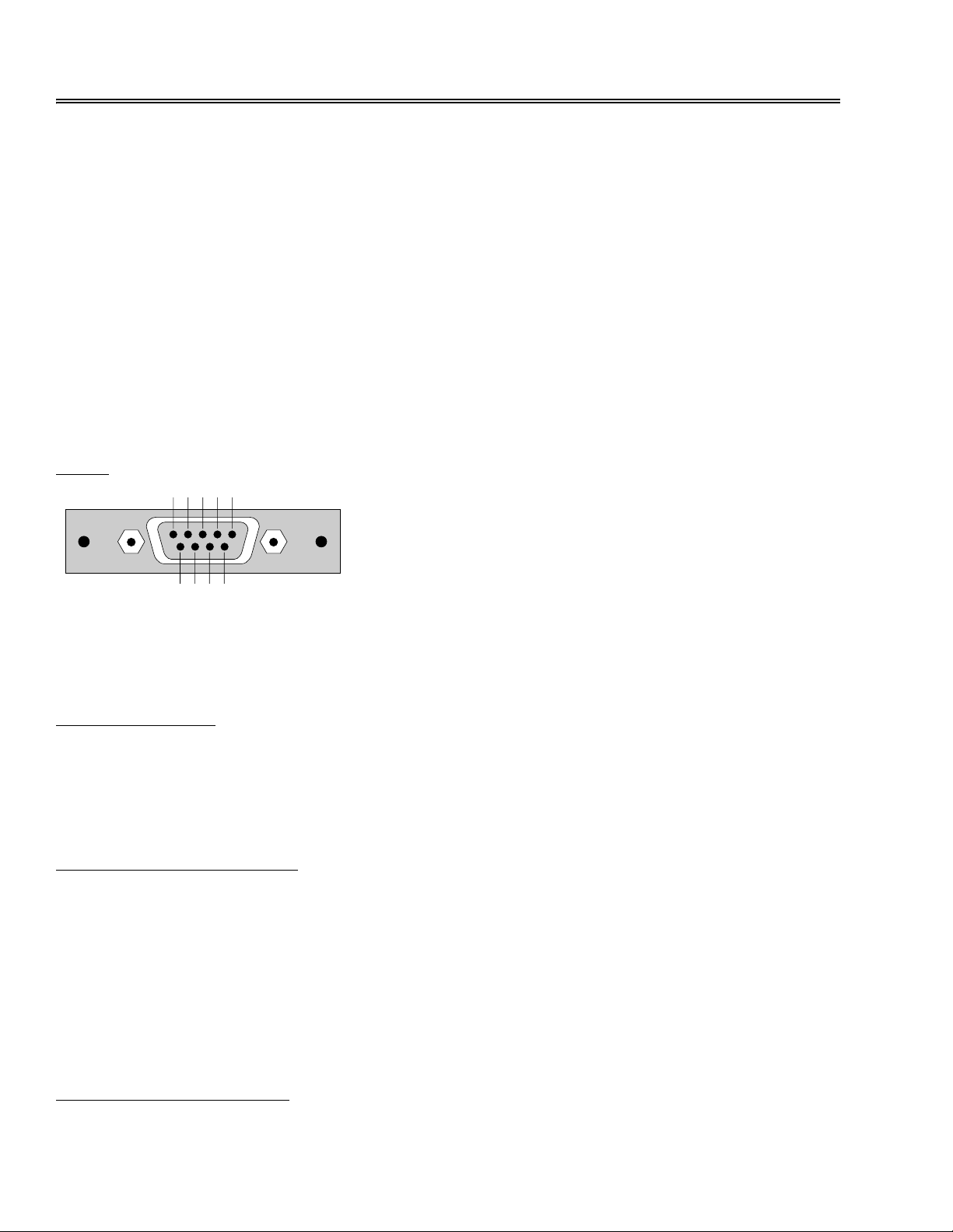
Pinout
Transmit: Pin 2 (Transmit from Serial Slot option to the PC)
Receive: Pin 3 (Receive from the PC to the Serial Slot option)
Signal GND: Pin 5
Serial Port Settings
Baud Rate: 9600
Data Bits: 8
Parity: None
Stop Bits: 1
The Command String Format
<cmd><parameters><CR>
Where:
<cmd> = The RS-232 command.
<parameters>= Optional parameters required by some commands.
<CR> = The Carriage Return character used to terminate the command.
All commands will be acknowledged, with either a simple acknowledgment string, or an error code, depending upon
the command’s successful execution.
The Acknowledgment String
+<CR><LF>
3

Where:
+ = The ‘+’ character.
<CR><LF> = The Carriage Return and Line feed characters.
Every command that does not cause an error will be responded to with the acknowledgement string. This includes
commands that request status. Status commands are acknowledge with this string, and then followed by the status
response string.
The Error Response
!<error code>
Where:
! = The ‘!’ character.
<error code>= An numeric ASCII value indicating the error encountered.
Any command that causes an error will be acknowledge with the error response string instead of a ‘+’ prefixed acknowledgement string.
For simple parsing of strings, the installer can simply look for the ‘+’ or ‘!’ in response to a command. Or the ‘!’ response can be more fully parsed to determine what caused the error.
The Status Response String
=<cmd><parameter><CR><LF>
Where:
= = The ‘=’ character.
<cmd> = The status command’s command character.
<parameter> = The command’s status.
<CR><LF> = The carriage return / line feed characters.
Status commands returned from the RS-232 interface are easily parsed, for they all be gin with the ‘=’ character.
Status string:
=<cmd><status><CR><LF>
Where:
= = The ‘=’ character.
<status> = The status of the current command, usually a numeric ASCII value.
<CR><LF> = The Carriage Return and Line feed characters.
4

ZEKTOR
TM
The MAS3
Serial Option
5

The MAS3 Command Set
Power Control
P0<CR> Turn off power
P1<CR> Turn on power
P+<CR> Toggle power
P?<CR> Request power status
Select Channel
C1<CR> Select Channel 1 (Note 1)
C2<CR> Select Channel 2 (Note 1)
C3<CR> Select Channel 3 (Note 1)
C+<CR> Select the next higher channel (Note 2)
C-<CR> Select the next lower channel (Note 2)
C?<CR> Request current channel status (Note 3)
Note 1: If power is off, this command will turn on power and then select the specified channel.
Note 2: If power is off, this command will be ignored.
Note 3: Returns channel status, if power is off, returns channel to be selected when power is applied.
Set Front Panel Lamp Intensities
L0<CR> Set lamps to the dim setting
L1<CR> Set lamps to the bright setting
L2<CR> Set lamps to the auto-dim setting
L+<CR> Cycle through intensity settings
L?<CR> Request the current intensity status
6

Auto Status Control
X0<CR> Turn off auto-status transmissions
X1<CR> Turn on auto-status transmissions
X?<CR> Request current auto status setting
The MAS3 can be set to send a status message when any of the following occur (outside of an RS-23 2 command):
• A new channel is selected. Sends a Channel Status string
• The power state changes. Sends a Power Status string
• The state of the lamp intensity changes. Sends a Lamp Status string
The responses are identical to the responses you receive when you request the information using the “?” parameter
for each of the above commands.
When ‘X0<CR>’ is issued, these above actions will not automatically be sent, but will be buffered.
When ‘X1<CR>’ is issued, any pending status messages will be sent, and from then on, any of the above actions
will cause a status message to be immediately sent.
Status changes made through the RS-232 will not cause the above status strings to be automatically sent. For in-
stance, a button press will send a Channel Status string, an IR remote Channel change will send a Channel Status
string, however the command ‘C+<CR>’ will only be followed by the ‘+<CR><LF>’ acknowledgement string.
See the section on MAS3 status strings for the syntax of the status strings.
Query Command Status
Q<CR> Request information on MAS3 command states
If the command ‘X0<CR>’ has been issued then command statuses will not be immediately sent but instead buffered. This command returns a bitmap that indicates what statuses are buffered and need to be read.
See the section on MAS3 status strings for the syntax of the returned string.
Save Current State As Power On Default
S<CR> Save MAS3’s current state as the power on default
Request Version
V<CR> Request the MAS3’s version
7

The MAS3 Response Strings
The section list the strings returned from the MAS3.
All MAS3 strings are terminated with the characters <CR><LF>.
Strings will start with only one of three characters:
‘+’ - Acknowledgement of a valid command.
‘!’ - Command caused an error (followed by the error code).
‘=’ - Start of a status string (followed by the status string).
Acknowledgement String
+<CR><LF> Acknowledge an error free command.
Acknowledge an error free command was received b y the MAS3 . All commands a re acknowledge d with eith er this
string or the Error Code String if an error occurred processing the command.
Error Code String
!<error><CR><LF> Indicate an error in the previous command.
The response to a command that caused an error.
<error>= A single digit ASCII value that indicates the error.
1 - Unknown command.
2 - Error in command’s parameters (out of range, or invalid).
Power Status String
=P<power><CR><LF> Return the current power state
<power> = A one digit ASCII value that indicates the power state of the MAS3
0 - MAS3 is OFF.
1 - MAS3 in ON.
Channel Status String
=C<chan><CR><LF> Return the current channel
<chan> = A one digit ASCII value that indicate the current channel of the MAS3.
1 - MAS3 is set to channel 1.
2 - MAS3 is set to channel 2.
3 - MAS3 is set to channel 3.
Lamp Intensity Setting
=L<setting><CR><LF> Return the current lamp intensity state
<setting> = A one digit ASCII value that indicates the current Lamp Intensity setting.
0 - Dim setting.
1 - Bright setting.
8

2 - Automatic bright to dim setting.
Query Command Status String
=Q<pending><CR><LF> Return buffered status state of the MAS3
<pending> = A one digit ASCII value that indicates the pending status commands.
0 - No commands pending.
1 - Power status string is pending.
2 - Channel status string is pending.
3 - Power & Channel status strings are pending.
4 - Lamp Intensity status string is pending.
5 - Power & Lamp status strings are pending.
6 - Channel & Lamp status strings are pending.
7 - Power, Channel & Lamp status strings are pending.
If a ‘X1<CR>’ command has been issued to the MAS3, then the results of the ‘Q?<CR>’ command will always be
0.
If a ‘X0<CR>’ command has been issued and any of the above states change, the command will be buffered await-
ing the proper status request to be issued. This command string returns a status of which MAS3 states have
changed and need to be read by the controller.
Version Status String
=V<version><CR><LF> Return the MAS3 version string.
<version> = A string of ASCII characters that identifies the MAS3 and its version.
9

10

ZEKTOR
TM
The HDS4.2
Serial Option
11

The HDS4.2 Command Set
Power Control
P0<CR> Turn off power
P1<CR> Turn on power
P+<CR> Toggle power
P?<CR> Request power status
Button Emulation
B1<CR> Same as pressing Select 1 Button
B2<CR> Same as pressing Select 2 Button
B3<CR> Same as pressing Select 3 Button
B4<CR> Same as pressing Select 4 Button
B5<CR> Same as pressing Power Button
B?<CR> Request pending button status (Note 1)
The ‘B’ command is only available on firmware versions 1.1 or later.
Note1: This returns the last button pressed on the HDS4.2 front panel, and not the last ‘Bx’ command sent to the
HDS4.2. A value of ‘B0’ will be sent if no button on the HDS4.2 has been pressed since power was applied.
Select Channel
C1<CR> Select Channel 1 (Note 1)
C2<CR> Select Channel 2 (Note 1)
C3<CR> Select Channel 3 (Note 1)
C4<CR> Select Channel 4 (Note 1)
C+<CR> Select the next higher channel (Note 2)
C-<CR> Select the next lower channel (Note 2)
C?<CR> Request current channel status (Note 3)
Note 1: If power is off, this command will turn on power and then select the specified channel.
Note 2: If power is off, this command will be ignored.
Note 3: Returns channel status, if power is off, returns channel to be selected when power is applied.
Set Front Panel Lamp Mode
L0<CR> Set lamps to the dim setting
L1<CR> Set lamps to the bright setting
L2<CR> Set lamps to the auto-dim setting
L3<CR> Turn off front panel LEDs (Note 1).
L+<CR> Cycle through intensity settings 0-2.
L?<CR> Request the current intensity status
Note 1: When Front Panel lights are turned off, the user has no way of knowing unit is powered on, or what channel
is selected. This setting should only be used when the HDS4.2 is fully under serial control. The ‘L3’ (turn
off front panel LEDs) is only available on firmware versions 1.1 or later.
12

Set Front Panel Intensities
I<min><space><max> Set the minimum and maximum front panel intensities.
Where:
<min> = The minumum (dim) intensity level of the front panel LEDs (0-255).
<max> = The maximum (bright) intensity level of the front panel LEDs (1-255).
Minimum intensity must be less than the maximum intensity.
If <min> is set to zero (LEDs blanked) the DIM Lamp Mode setting ‘L0’ will no longer be available. When attempting
to set the Lamp Mode to DIM, BRIGHT will be used instead. This keeps the user from inadvertantly turning off the
front panel LEDs by setting the DIM mode using the IR remote . The proper way to turn off the front panel is by issuing
the ‘L3’ command.
The ‘I’ command is only available on firmware versions 1.1 or later.
Control Bits
X<ControlBits>0<CR>
Where:
ControlBits = Status control bits. This is a bitmapped value, given in decimal.
Bit 7 6 5 4 3 2 1 0
00000IR KB AS
0 Reserved, always set to 0.
IR 0=Normal IR (default), 1=IR control disabled.
KB 0=Normal Keyboard (default), 1=Keyboard selection disabled.
AS 0=Auto-status off (Polled Mode), 1=Auto-status transmissions enabled.
X?<CR> Request current ControlBits setting
The HDS4.2 can be set to send a status message when any of the followin g occur (outside of an RS-232 command):
• A new channel is selected. Sends a Channel Status string
• The power state changes. Sends a Power Status string
• The state of the lamp intensity changes. Sends a Lamp Status string
• A button is pressed on the front panel. Sends a Button Status string (Note 1)
The responses are identical to the responses you receive when you request the information using the “?” parameter
for each of the above commands.
When ‘X0<CR>’ is issued, these above actions will not automatically be sent, but will be buffered.
When ‘X1<CR>’ is issued, any pending status messages will be sent, and from then on, any of the above actions
will cause a status message to be immediately sent.
Status changes made through the RS-232 will not cause the above status strings to be automatically sent. For in-
stance, a button press will send a Channel Status string, an IR remote Channel change will send a Channel Status
string, however the command ‘C+<CR>’ will only be followed by the ‘+<CR><LF>’ acknowledgement string.
See the section on HDS4.2 status strings for the syntax of the status strings.
Note 1: The Button Status string is only sent automatically when the HDS4.2 front panel is disabled and the ’AS’
Note 2: The ‘IR’ and ‘KB’ bits are only available in firmware version 1.1 or later.
bit is set to ‘0’.
Query Command Status
Q<CR> Request information on HDS4.2 command states
If the command ‘X0<CR>’ has been issued then command statuses will not be immediately sent but instead buffered. This command returns a bitmap that indicates what statuses are buffered and need to be read.
See the section on HDS4.2 status strings for the syntax of the returned string .
13

Save Current State As Power On Default
S<CR> Save HDS4.2’s current state as the power on default
Request Version
V<CR> Request the HDS4.2’s version
14

The HDS4.2 Response Strings
The section list the strings returned from the HDS4.2.
All HDS4.2 strings are terminated with the characters <CR><LF>.
Strings will start with only one of three characters:
‘+’ - Acknowledgement of a valid command.
‘!’ - Command caused an error (followed by the error code).
‘=’ - Start of a status string (followed by the status string).
Acknowledgement String
+<CR><LF> Acknowledge an error free command.
Acknowledge an error free command was received by the HDS4 .2. All commands are acknowledged with either this
string or the Error Code String if an error occurred processing the command.
Error Code String
!<error><CR><LF> Indicate an error in the previous command.
The response to a command that caused an error.
<error>= A single digit ASCII value that indicates the error.
1 - Unknown command.
2 - Error in command’s parameters (out of range, or invalid).
5 - Bad number of parameters in command line.
Power Status String
=P<power><CR><LF> Return the current power state
<power> = A one digit ASCII value that indicates the power state of the HDS4.2
0 - HDS4.2 is OFF.
1 - HDS4.2 in ON.
Channel Status String
=C<chan><CR><LF> Return the current channel
<chan> = A one digit ASCII value that indicate the current channel of the HDS4.2.
1 - HDS4.2 is set to channel 1.
2 - HDS4.2 is set to channel 2.
3 - HDS4.2 is set to channel 3.
4 - HDS4.2 is set to channel 4.
15

Button Press
=B<button><CR><LF>
<button> = A one digit ASCII value that indicates the last button pressed on the front panel.
1 - Switch to channel 1 button.
2 - Switch to channel 2 button.
3 - Switch to channel 3 button.
4 - Switch to channel 4 button.
5 - Power button.
Lamp Mode Setting
=L<setting><CR><LF>
<setting> = A one digit ASCII value that indicates the current Lamp Intensity setting.
0 - Dim setting.
1 - Bright setting.
2 - Automatic bright to dim setting.
3 - Front panel LEDs turned off. (Note 1)
Note 1: The ‘3’ setting (turn off front panel LEDs) is only available in firmware versions 1.1 and later.
Lamp Intensity Setting
=I<min><space><max><CR><LF>
<min> = Minimum (dim) intensity of front panel LEDs (Range: 0 - 255).
<max> = Maximum (bright) intensity of front panel LEDs (Range: 1 - 255).
The ‘I’ command is only available in firmware versions 1.1 and later.
Query Command Status String
=Q<PendingBits><CR><LF> Return buffered status state of the DVS5.1
<PendingBits> = A bitmapped value that indicates the pending status commands.
Bit 7 6 5 4 3 2 1 0
0000KB LI CS PS
PS - Power status string is pending when set.
CS - Channel status string is pending when set.
LI - Lamp Intensity status string is pending when set.
KB - Keypress pending, waiting to be read, when set. (Note 1)
0 - Unused, always returned as 0.
If an ‘X0<CR>’ command has been issued and any of the above states have change, the command’s status will
be buffered awaiting the proper request to be issued by the controller. This command returns a status of which
HDS4.2 states have changed and need to be read by the controller.
If an ‘X1<CR>’ command has been issued to the HDS4.2, then the results of the ‘Q?<CR>’ command will always
be 0.
Note 1: The ‘KB’ bit is only available in firmware versions 1.1 and later.
Version Status String
=V<version><CR><LF> Return the HDS4.2 version string.
<version> = A string of ASCII characters that identifies the HDS4.2 and its version.
16

17

ZEKTOR
TM
The DVS5.1
Serial Option
18

The DVS5.1 Command Set
Power Control
P0<CR> Turn off power
P1<CR> Turn on power
P+<CR> Toggle power
P?<CR> Request power status
Button Emulation
B1<CR> Same as pressing Select 1 Button
B2<CR> Same as pressing Select 2 Button
B3<CR> Same as pressing Select 3 Button
B4<CR> Same as pressing Select 4 Button
B5<CR> Same as pressing Select 5 Button
B6<CR> Same as pressing Audio Button
B7<CR> Same as pressing Power Button
B?<CR> Request pending button status (Note 1)
Note1: This returns the last button pressed on the DVS5.1 front panel, and not the last ‘Bx’ comma nd s en t to th e
DVS5.1. A value of ‘B0’ will be sent if no button on the DVS5.1 has been pressed since power was applied.
Select Channel
C<VideoChan>[<space><AudioChan>]<CR>Select Channel (Note 1)
Where:
VideoChan = Selected video input (Range: 1-5)
AudioChan = Selected audio input (Range: 1-5)(Optional)
C+<CR> Select the next higher channel (Note 2)
C-<CR> Select the next lower channel (Note 2)
C?<CR> Request current channel status (Note 3)
Note 1: If power is off, this command will turn on power and then select the specified channel. The ‘[<space><Au-
dioChan>]’ is optional (don’t include the ‘[‘ and ‘]’ in the command string) and are used to enabled the
Audio Break away feature. If not given then both Video and Audio will be switched to the selected channel.
Note 2: If power is off, this command will be ignored. AudioBreak, if enabled, will be disabled. The new selection will
be based on the current video selection.
Note 3: Returns channel status, if power is off, returns channel to be selected when power is applied.
Button Press
=B<button><CR><LF>
<button> = A one digit ASCII value that indicates the last button pressed on the front panel.
1 - Switch to channel 1 button.
2 - Switch to channel 2 button.
3 - Switch to channel 3 button.
4 - Switch to channel 4 button.
5 - Power button.
19

Set Front Panel Lamp Mode
L0<CR> Set lamps to the dim setting
L1<CR> Set lamps to the bright setting
L2<CR> Set lamps to the auto-dim setting
L3<CR> Turn off front panel LEDs (Note 1).
L+<CR> Cycle through intensity settings 0-2.
L?<CR> Request the current intensity status
Note 1: When Front Panel lights are turned off, the user has no way of knowing unit is powered on, or what channel
is selected. This setting should only be used when the DVS5.1 is fully under serial control.
Set Front Panel Intensities
I<min><space><max> Set the minimum and maximum front panel intensities.
Where:
<min> = The minumum (dim) intensity level of the front panel LEDs (0-255).
<max> = The maximum (bright) intensity level of the front panel LEDs (1-255).
Minimum intensity must be less than the maximum intensity.
If <min> is set to zero (LEDs blanked) the DIM Lamp Mode setting ‘L0’ will no longer be available. When
attempting to set the Lamp Mode to DIM, BRIGHT will be used instead. This keeps the user from inadvertantly turning off the front panel LEDs by setting the DIM mode using the IR remo te. The pro per way to turn
off the front panel is by issuing the ‘L3’ command.
20

Control Bits
X<ControlBits>0<CR>
Where:
ControlBits = Status control bits. This is a bitmapped value, given in decimal.
Bit 7 6 5 4 3 2 1 0
00000IR KB AS
0 Reserved, always set to 0.
IR 0=Normal IR (default), 1=IR control disabled.
KB 0=Normal Keyboard (default), 1=Keyboard selection disabled.
AS 0=Auto-status off (Polled Mode), 1=Auto-status transmissions enabled.
X?<CR> Request current ControlBits setting
The DVS5.1 can be set to send a status message when any of the following occur (outside of an RS-232 command):
• A new channel is selected. Sends a Channel Status string
• The power state changes. Sends a Power Status string
• The state of the lamp intensity changes. Sends a Lamp Status string
• A front panel button is pressed. Sends a Button Status string (Note 1)
The responses are identical to the responses you receive when you request the information using the “?” parameter
for each of the above commands.
When ‘X0<CR>’ is issued, these above actions will not automatically be sent, but will be buffered.
When ‘X1<CR>’ is issued, any pending status messages will be sent, and from then on, any of the above actions
will cause a status message to be immediately sent.
Status changes made through the RS-232 will not cause the above status strings to be automatically sent. For in-
stance, a button press will send a Channel Status string, an IR remote Channel change will send a Channel Status
string, however the command ‘C+<CR>’ will only be followed by the ‘+<CR><LF>’ acknowledgement string.
See the section on DVS5.1 status strings for the syntax of the status strings.
Note 1: The Button Status string is only sent automatically when the DVS5.1 front panel is disabled and the ’AS’
bit is set to ‘0’.
Query Command Status
Q<CR> Request information on DVS5.1 command states
If the command ‘X0<CR>’ has been issued then command statuses will not be immediately sent but instead buffered. This command returns a bitmap that indicates what statuses are buffered and need to be read.
See the section on DVS5.1 status strings for the syntax of the returned string.
Save Current State As Power On Default
S<CR> Save DVS5.1’s current state as the power on default
Request Version
V<CR> Request the DVS5.1’s version
21

The DVS5.1 Response Strings
The section list the strings returned from the DVS5.1.
All DVS5.1 strings are terminated with the characters <CR><LF>.
Strings will start with only one of three characters:
‘+’ - Acknowledgement of a valid command.
‘!’ - Command caused an error (followed by the error code).
‘=’ - Start of a status string (followed by the status string).
Acknowledgement String
+<CR><LF> Acknowledge an error free command.
Acknowledge an error free command was received by the DVS5.1. All comm ands are acknowledged with either this
string or the Error Code String if an error occurred processing the command.
Error Code String
!<error><CR><LF> Indicate an error in the previous command.
The response to a command that caused an error.
<error>= A single digit ASCII value that indicates the error.
1 - Unknown command.
2 - Error in command’s parameters (out of range, or invalid).
5 - Bad number of parameters in command line.
Power Status String
=P<power><CR><LF> Return the current power state
<power> = A one digit ASCII value that indicates the power state of the DVS5.1
0 - DVS5.1 is OFF.
1 - DVS5.1 in ON.
Channel Status String
=C<VideoChan><space><AudioChan><CR><LF>Return channel selection
<VideoChan> = A one digit ASCII value that indicates the current video selection.
Video Channel return values range between 1 and 5.
<AudioChan> = A one digit ASCII value that indicates the current audio selection.
Audio Channel return values range between 1 and 5.
22

Button Press
=B<button><CR><LF>
<button> = A one digit ASCII value that indicates the last button pressed on the front panel.
1 - Switch to channel 1 button.
2 - Switch to channel 2 button.
3 - Switch to channel 3 button.
4 - Switch to channel 4 button.
5 - Power button.
Lamp Mode Setting
=L<setting><CR><LF>
<setting> = A one digit ASCII value that indicates the current Lamp Intensity setting.
0 - Dim setting.
1 - Bright setting.
2 - Automatic bright to dim setting.
3 - Front panel LEDs turned off.
Lamp Intensity Setting
=I<min><space><max><CR><LF>
<min> = Minimum (dim) intensity of front panel LEDs (Range: 0 - 255).
<max> = Maximum (bright) intensity of front panel LEDs (Range: 1 - 255).
Query Command Status String
=Q<PendingBits><CR><LF> Return buffered status state of the DVS5.1
<PendingBits> = A bitmapped value that indicates the pending status commands.
Bit 7 6 5 4 3 2 1 0
0000KB LI CS PS
PS - Power status string is pending when set.
CS - Channel status string is pending when set.
LI - Lamp Intensity status string is pending when set.
KB - Keypress pending, waiting to be read, when set.
0 - Unused, always returned as 0.
If an ‘X0<CR>’ command has been issued and any of the above states have change, the command’s status will
be buffered awaiting the proper request to be issued by the controller. This command returns a status of which
DVS5.1 states have changed and need to be read by the controller.
If an ‘X1<CR>’ command has been issued to the DVS5.1, then the results of the ‘Q?<CR>’ command will always
be 0.
Version Status String
=V<version><CR><LF> Return the DVS5.1 version string.
<version> = A string of ASCII characters that identifies the DVS5.1 and its version.
23

Customer Service contact information:
ZEKTOR, LLC
12675 Danielson Court
Suite 401
Poway, CA 92064
Phone: 858-748-8250
Email: customerservice@zektor.com
24
 Loading...