


 Loading...
Clarity Audio 16x16
User Guide
and
Serial & TCP/IP Protocols
Advanced Audio 16x16 Matrix Switch
(For ClarityAudio firmware Versions 1.00 and above.)

History
2012-11-08 Version 1.01
•Fixed typos.
•Document the ‘DZ’ command.
•Document the TCP/IP related commands.
2012-09-26 Version 1.00
•Initial Release.
2 |
ClarityAudio User Guide, Version 1.01, 11/8/12 |

RS-232 / TCP/IP Port Hardware . . . . . . . . . . . . . . . . . . . . . . . . . . . . . . . . . . . . . . . . .3
TCP/IP Overview . . . . . . . . . . . . . . . . . . . . . . . . . . . . . . . . . . . . . . . . . . . . . . . . . . . . . . . . . . . . . . . . . . 3
Setting a static IP address vs DHCP. . . . . . . . . . . . . . . . . . . . . . . . . . . . . . . . . . . . . . . . . . . . . . . . . . . . . . . . . 3
Default TCP/IP settings used by the ClarityAudio. . . . . . . . . . . . . . . . . . . . . . . . . . . . . . . . . . . . . . . . . . . . . . 3
RS-232 Pinout and Baudrate Settings . . . . . . . . . . . . . . . . . . . . . . . . . . . . . . . . . . . . . . . . . . . . . . . . . . 4
Pin definitions: . . . . . . . . . . . . . . . . . . . . . . . . . . . . . . . . . . . . . . . . . . . . . . . . . . . . . . . . . . . . . . . . . . . . . . . . . . 4 Port settings used by the ClarityAudio: . . . . . . . . . . . . . . . . . . . . . . . . . . . . . . . . . . . . . . . . . . . . . . . . . . . . . . 4 Timing information: . . . . . . . . . . . . . . . . . . . . . . . . . . . . . . . . . . . . . . . . . . . . . . . . . . . . . . . . . . . . . . . . . . . . . . 4
Command Syntax . . . . . . . . . . . . . . . . . . . . . . . . . . . . . . . . . . . . . . . . . . . . . . . . . . . .5
Command Syntax . . . . . . . . . . . . . . . . . . . . . . . . . . . . . . . . . . . . . . . . . . . . . . . . . . . . . . . . . . . . . . . . . 5 Command Responses . . . . . . . . . . . . . . . . . . . . . . . . . . . . . . . . . . . . . . . . . . . . . . . . . . . . . . . . . . . . . . 5
Type of Responses and Timing Information . . . . . . . . . . . . . . . . . . . . . . . . . . . . . . . . . . . . . . . . . . . . . . . . . . 5 The Acknowledgement Response . . . . . . . . . . . . . . . . . . . . . . . . . . . . . . . . . . . . . . . . . . . . . . . . . . . . . . . . . . 5 The Error Response . . . . . . . . . . . . . . . . . . . . . . . . . . . . . . . . . . . . . . . . . . . . . . . . . . . . . . . . . . . . . . . . . . . . . . 6
The Query Response . . . . . . . . . . . . . . . . . . . . . . . . . . . . . . . . . . . . . . . . . . . . . . . . . . . . . . . . . . . . . . . . . . . . . 6
Using Bitmapped Parameters . . . . . . . . . . . . . . . . . . . . . . . . . . . . . . . . . . . . . . . . . . . . . . . . . . . . . . . . 7
Reading / Writing Bitmapped Parameters . . . . . . . . . . . . . . . . . . . . . . . . . . . . . . . . . . . . . . . . . . . . . . . . . . . . 7
Basic Control . . . . . . . . . . . . . . . . . . . . . . . . . . . . . . . . . . . . . . . . . . . . . . . . . . . . . . .8
Reference for Basic Control Commands . . . . . . . . . . . . . . . . . . . . . . . . . . . . . . . . . . . . . . . . . . . . . . . . 8
Definitions . . . . . . . . . . . . . . . . . . . . . . . . . . . . . . . . . . . . . . . . . . . . . . . . . . . . . . . . . . . . . . . . . . . . . . . . . . . . . . 8
Zone . . . . . . . . . . . . . . . . . . . . . . . . . . . . . . . . . . . . . . . . . . . . . . . . . . . . . . . . . . . . . . . . . . . . . . . . . . . . . . . 8 Input . . . . . . . . . . . . . . . . . . . . . . . . . . . . . . . . . . . . . . . . . . . . . . . . . . . . . . . . . . . . . . . . . . . . . . . . . . . . . . . 8 Channel. . . . . . . . . . . . . . . . . . . . . . . . . . . . . . . . . . . . . . . . . . . . . . . . . . . . . . . . . . . . . . . . . . . . . . . . . . . . . 8
Basic Control Commands . . . . . . . . . . . . . . . . . . . . . . . . . . . . . . . . . . . . . . . . . . . . . . . . . . . . . . . . . . . . . . . . . 9
Basic Command Definitions. . . . . . . . . . . . . . . . . . . . . . . . . . . . . . . . . . . . . . . . . . . . . . . . . . . . . . . . . . 9
‘P’ Power Control . . . . . . . . . . . . . . . . . . . . . . . . . . . . . . . . . . . . . . . . . . . . . . . . . . . . . . . . . . . . . . . . . . . . . . . . 9 ‘SZ’ Set Zone(s) (input / output mappings) . . . . . . . . . . . . . . . . . . . . . . . . . . . . . . . . . . . . . . . . . . . . . . . . . . . 9 ‘MZ’ Mute Zone(s) . . . . . . . . . . . . . . . . . . . . . . . . . . . . . . . . . . . . . . . . . . . . . . . . . . . . . . . . . . . . . . . . . . . . . . . 12 ‘DZ’ Set Zone Switching Delays . . . . . . . . . . . . . . . . . . . . . . . . . . . . . . . . . . . . . . . . . . . . . . . . . . . . . . . . . . . 12
Audio Control . . . . . . . . . . . . . . . . . . . . . . . . . . . . . . . . . . . . . . . . . . . . . . . . . . . . . .14
Reference for Audio Control Commands . . . . . . . . . . . . . . . . . . . . . . . . . . . . . . . . . . . . . . . . . . . . . . . 14
Audio Control Commands . . . . . . . . . . . . . . . . . . . . . . . . . . . . . . . . . . . . . . . . . . . . . . . . . . . . . . . . . . . . . . . . 14
Audio Command Definitions . . . . . . . . . . . . . . . . . . . . . . . . . . . . . . . . . . . . . . . . . . . . . . . . . . . . . . . . 14
‘MV’ Set Master Volume . . . . . . . . . . . . . . . . . . . . . . . . . . . . . . . . . . . . . . . . . . . . . . . . . . . . . . . . . . . . . . . . . . 14 ‘VZ’ Set Zone’s Volume . . . . . . . . . . . . . . . . . . . . . . . . . . . . . . . . . . . . . . . . . . . . . . . . . . . . . . . . . . . . . . . . . . 15 ‘VMIZ’ Set Zone’s Minimum Volume . . . . . . . . . . . . . . . . . . . . . . . . . . . . . . . . . . . . . . . . . . . . . . . . . . . . . . . . 17 ‘VMAZ’ Set Zone’s Maximum Volume . . . . . . . . . . . . . . . . . . . . . . . . . . . . . . . . . . . . . . . . . . . . . . . . . . . . . . . 18 ‘VPZ’ Set Zone’s Volume as a Percentage . . . . . . . . . . . . . . . . . . . . . . . . . . . . . . . . . . . . . . . . . . . . . . . . . . . 18 ‘VRT’ Set Volume Ramp (Fade) Times . . . . . . . . . . . . . . . . . . . . . . . . . . . . . . . . . . . . . . . . . . . . . . . . . . . . . . 19 ‘VMZ’ Mute a Zone using Volume Control . . . . . . . . . . . . . . . . . . . . . . . . . . . . . . . . . . . . . . . . . . . . . . . . . . . 19 ‘VMLZ’ Set a Zone’s Mute Level . . . . . . . . . . . . . . . . . . . . . . . . . . . . . . . . . . . . . . . . . . . . . . . . . . . . . . . . . . . 20 ‘VMT’ Set Muting (Fade) Times . . . . . . . . . . . . . . . . . . . . . . . . . . . . . . . . . . . . . . . . . . . . . . . . . . . . . . . . . . . . 21 ‘BLZ’ Set Zone’s Balance. . . . . . . . . . . . . . . . . . . . . . . . . . . . . . . . . . . . . . . . . . . . . . . . . . . . . . . . . . . . . . . . . 21 ‘GAZ’ Set Zone’s Gain (Output Levels). . . . . . . . . . . . . . . . . . . . . . . . . . . . . . . . . . . . . . . . . . . . . . . . . . . . . . 22 ‘GAI’ Set Input’s Gain (Input Trimming) . . . . . . . . . . . . . . . . . . . . . . . . . . . . . . . . . . . . . . . . . . . . . . . . . . . . . 22 ‘BAZ’, ‘TRZ’ Set Zone’s Bass and Treble Levels . . . . . . . . . . . . . . . . . . . . . . . . . . . . . . . . . . . . . . . . . . . . . . 23 ‘EQ1Z’, ‘EQ2Z’, ‘EQ3Z’, ‘EQ4Z’, ‘EQ5Z’ Set the 5 Band Equalizers’ levels . . . . . . . . . . . . . . . . . . . . . . . . . 24 ‘MXZ’ Stereo to Mono Down Mix for a Zone. . . . . . . . . . . . . . . . . . . . . . . . . . . . . . . . . . . . . . . . . . . . . . . . . . 25 ‘DRZ’ Non-PCM Digital audio Routing . . . . . . . . . . . . . . . . . . . . . . . . . . . . . . . . . . . . . . . . . . . . . . . . . . . . . . 26 ‘LSZ’ Set Lip Sync delay for a Zone . . . . . . . . . . . . . . . . . . . . . . . . . . . . . . . . . . . . . . . . . . . . . . . . . . . . . . . . 26 ‘LSI’ Set Lip Sync delay for an Input. . . . . . . . . . . . . . . . . . . . . . . . . . . . . . . . . . . . . . . . . . . . . . . . . . . . . . . . 27
Advanced Control. . . . . . . . . . . . . . . . . . . . . . . . . . . . . . . . . . . . . . . . . . . . . . . . . . .29
Reference for Advance Control Commands . . . . . . . . . . . . . . . . . . . . . . . . . . . . . . . . . . . . . . . . . . . . 29
Advanced Control Commands . . . . . . . . . . . . . . . . . . . . . . . . . . . . . . . . . . . . . . . . . . . . . . . . . . . . . . . . . . . . 29
Advanced Command Definitions . . . . . . . . . . . . . . . . . . . . . . . . . . . . . . . . . . . . . . . . . . . . . . . . . . . . . 29
‘V’ Version . . . . . . . . . . . . . . . . . . . . . . . . . . . . . . . . . . . . . . . . . . . . . . . . . . . . . . . . . . . . . . . . . . . . . . . . . . . . . 29 ‘QI’ Query for Zone, Input and Channel Information . . . . . . . . . . . . . . . . . . . . . . . . . . . . . . . . . . . . . . . . . . . 29 ‘XS’ Control Settings . . . . . . . . . . . . . . . . . . . . . . . . . . . . . . . . . . . . . . . . . . . . . . . . . . . . . . . . . . . . . . . . . . . . 30
‘ACK’ Enable / Disable Acknowledgements . . . . . . . . . . . . . . . . . . . . . . . . . . . . . . . . . . . . . . . . . . . . . . 31 ‘ECO’ Enable / Disable the ‘Parameter Changed’ Strings . . . . . . . . . . . . . . . . . . . . . . . . . . . . . . . . . . . 31 ‘CHM’ Enable / Disable always sending“.ch” masks on zone commands. . . . . . . . . . . . . . . . . . . . . . 31 ‘CRE’ Enable / Disable trailing Carriage Returns Line Feeds . . . . . . . . . . . . . . . . . . . . . . . . . . . . . . . . 31 ‘AUT’ Enable / Disable Auto Conversion of Analog / Digital Paths. . . . . . . . . . . . . . . . . . . . . . . . . . . . 31
‘SS’ Save Default Power On Settings . . . . . . . . . . . . . . . . . . . . . . . . . . . . . . . . . . . . . . . . . . . . . . . . . . . . . . . 32
‘FS’ Reset to Factory Settings. . . . . . . . . . . . . . . . . . . . . . . . . . . . . . . . . . . . . . . . . . . . . . . . . . . . . . . . . . . . . 32
TCP/IP Control. . . . . . . . . . . . . . . . . . . . . . . . . . . . . . . . . . . . . . . . . . . . . . . . . . . . . . . . . . . . . . . . . . . 34
ClarityAudio Serial Protocol, Version 1.01, 11/8/12 |
1 |

‘IPSET’ Set the IP operation mode, DHCP or STATIC . . . . . . . . . . . . . . . . . . . . . . . . . . . . . . . . . . . . . . . . . . 34 ‘IPA’ Set / View the static IP Address . . . . . . . . . . . . . . . . . . . . . . . . . . . . . . . . . . . . . . . . . . . . . . . . . . . . . . . 35 ‘IPM’ Set / View the static IP Mask . . . . . . . . . . . . . . . . . . . . . . . . . . . . . . . . . . . . . . . . . . . . . . . . . . . . . . . . . 35 ‘IPG’ Set / View the static IP gateway address . . . . . . . . . . . . . . . . . . . . . . . . . . . . . . . . . . . . . . . . . . . . . . . 35 ‘IPAX’ Retrieve the current IP address in use . . . . . . . . . . . . . . . . . . . . . . . . . . . . . . . . . . . . . . . . . . . . . . . . 36 ‘IPMX’ Retrieve the current IP mask in use . . . . . . . . . . . . . . . . . . . . . . . . . . . . . . . . . . . . . . . . . . . . . . . . . . 36 ‘IPGX’ Retrieve the current IP gateway address in use . . . . . . . . . . . . . . . . . . . . . . . . . . . . . . . . . . . . . . . . 36
2 |
ClarityAudio Serial Protocol, Version 1.01, 11/8/12 |

RS-232 / TCP/IP Port Hardware
RS-232 / TCP/IP Port Hardware
TCP/IP Overview
The Serial and TCP/IP port share the same protocol.
The TCP/IP connection is a very simple socket, sometimes referred to as Raw TCP/IP socket, similar to Telnet, but without the Telnet protocol overhead. Most telnet clients will allow you to telnet into the ClarityAudio without error.
We use the open source package PuTTY to do our testing. It has a convenient “Raw” mode that works great with the ClarityAudio, and is available in Windows and Linux (with a Mac O/S version in the works). (We are not associated with PuTTY in anyway, but do find it a useful tool when communicating over TCP/IP and Serial port connections)
Website: http://www.chiark.greenend.org.uk/~sgtatham/putty
The default IP address mode is DHCP and the port address is 50005. The serial commands ‘IPA’, ‘IPM’, ‘IPG’, and ‘IPSET 0’ can be used to change the IP address, the port number is fixed at 50005.
(See: “‘IPSET’ Set the IP operation mode, DHCP or STATIC” on page 34)
Once a connection is made it will remain open until closed by the client, or after 10 minutes of retries at attempting to talk to the client.
After connecting to the TCP/IP port, all commands are identical to those of the Serial port. All strings coming from the ClarityAudio will be sent to both the TCP/IP and Serial port.
The ClarityAudio will accept commands from both the Serial and TCP/IP simultaneously, each command will be buffered until the ending ‘$’ is read, at which time the commands will be executed in the order received. Any responses will be sent to both the Serial port and TCP/IP connections.
Setting a static IP address vs DHCP
By default, the ClarityAudio will use DHCP to retrieve a IP address, an IP mask, and the address of the router.
Setting an IP address is a two step process. You must first set the static values to be used for the IP address, the IP mask, and the router address, then place the ClarityAudio into the Static IP address mode.
The commands to set the static IP address, mask and router are: IPA, IPM and IPG respectively. (See: “‘IPA’ Set / View the static IP Address” on page 35.)
The command to change the IP address mode is: IPSET. (See: “‘IPSET’ Set the IP operation mode, DHCP or STATIC” on page 34.)
The command to save these changes in EEPROM so that they are used after a power failure is: ‘^SS 32$’. (See: “‘SS’ Save Default Power On Settings” on page 32.)
As an example, to set a static address of 192.168.1.200, a mask of 255.255.255.0 and a router address of 192.168.1.1, and save this in EEPROM, the following commands would be executed:
^IPA 192,168,1,200$ |
- Set the static IP address |
^IPM 255,255,255,0$ |
- Set the static IP mask |
^IPG 192,168,1,1$ |
- Set the router address |
^IPSET 0$ |
- Set the TCP/IP mode to “Static” |
^SS 32$ |
- Save the new settings in EEPROM in case of power failure |
Default TCP/IP settings used by the ClarityAudio |
|
|
Default IP Setting: |
DHCP |
|
|
|
|
ClarityAudio Serial Protocol, Version 1.01, 11/8/12 |
3 |
|
RS-232 / TCP/IP Port Hardware
Port Number: |
50005 |
Duplex: |
Half/Full (auto detect) |
Speed: |
10/100 Mbps (auto detect) |
RS-232 Pinout and Baudrate Settings
The RS-232 port on the ClarityAudio is the same format, and pinout, as a PC modem, and uses the same type of cable as a standard serial modem would, which is a standard straight through cable. Do not use a cable that is marked as a “Null Modem” cable.
The ClarityAudio can also be used with any USB to RS-232 conversion cable, these are all typically straight through cables. (Be sure to install any drivers that come with the USB to RS-232 cable you are using.)
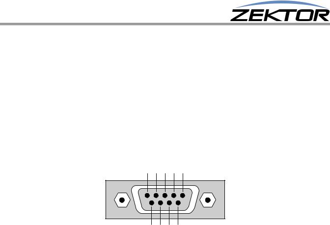
The RS-232 port is a female type DE-9 connector (sometimes mistakenly referred to as a DB-9 connector) with the following pinout:
|
|
|
|
Pin definitions: |
|
|
1 |
- No Connect |
6 - No Connect |
2 |
- TX |
7 - No Connect |
3 |
- RX |
8 - No Connect |
4 |
- No Connect |
9 - No Connect |
5 |
- GND |
|
Port settings used by the ClarityAudio:
Baudrate: |
19200 |
Data Bits: |
8 |
Stop Bits: |
1 |
Parity: |
NONE |
Timing information: |
|
Min character to character time: |
0ms |
Min line to line time: |
0ms |
Min time between commands: |
0ms |
Max time to respond to a request: 100ms (unless otherwise specified)
4 |
ClarityAudio Serial Protocol, Version 1.01, 11/8/12 |

Command Syntax
Command Syntax
Command Syntax
The ClarityAudio serial command set uses an ASCII based protocol and a terminal emulator can be used to test the serial port of the ClarityAudio.
Each serial command is formatted as:
^CMD param1,param2,...$
Where: |
|
^ |
= All commands and responses start with the ‘^’ character. |
CMD |
= The name of the command. |
param |
= Any number of parameters can follow a command. |
$ |
= All commands and responses end with the ‘$’ character. |
For instance the name of the command to turn power on / off is ‘P’ (must be capitalized) therefore, to turn on the ClarityAudio send:
^P 1$ |
-> Command sent to the A/V switch |
||
^+$ |
1$ |
<- |
Acknowledgment indicating valid command |
^=P |
<- |
Response from the A/Vswitch for new setting |
|
to turn off the ClarityAudio send:
^P 0$ |
-> Command sent to the A/V switch |
||
^+$ |
0$ |
<- |
Acknowledgment indicating valid command |
^=P |
<- |
Response from the A/V switch for new setting |
|
NOTE: Only the characters between ‘^’ and ‘$’ are valid, any characters sent before the ‘^’ or after the ‘$’ will be ignored.
NOTE: By default, the ClarityAudio adds a carriage return and a line feed to the end of its responses, after the ‘$’. This makes testing with terminal software easier. Since they are outside the ‘^’ and ‘$’ characters, they should be ignored by software drivers. If desired, this behavior can be disabled. (See:
“‘XS’ Control Settings” on page 30)
Command Responses
Type of Responses and Timing Information
There are three different types of responses: Acknowledgements, Errors and Query Strings.
By default, the ClarityAudio will always respond to a command, there are no “time-out” modes, if you send a command and don’t get a response within 100ms, something’s wrong with the connection.
The Acknowledgement Response
Every command will be followed by an acknowledgement or error response.
Anytime you issue a command and there are no errors, you will receive the acknowledgement response. Which is:
^+$
ClarityAudio Serial Protocol, Version 1.01, 11/8/12 |
5 |

Command Syntax
The Error Response
Every command will be followed by an acknowledgement or error response.
If something is wrong with the command, you will get an error response. Which is
^!<error_number>$
which is the ‘!’ followed by an error number (in ASCII), followed the ‘$’ character. For instance ‘2’ is not allowed as a parameter in the ‘P’ (power) command, so:
^P 2$ |
-> |
Command sent to A/V switch |
^!2$ |
<- |
Error response to an out of range parameter |
which indicates there was an out of range parameter.
The following are the Error Response codes that can be returned by the ClarityAudio:
1 - |
Unrecognized command. |
2 - |
A parameter was out of range. |
3 - |
Syntax error, or a badly formed command. |
5 - |
Too many or too few parameters. |
6 - |
Device busy, cannot process command. |
7 - |
Buffer overflow. |
8 - |
Command not valid if device is not powered on. |
100 - |
DSP Programmed successfully (not really an error). |
101 - 108 Error intiatializing the audio subsystem. And some more detailed descriptions of their meanings:
Error 1 - The command given was not recognized as a ClarityAudio command. Commands are case sensitive and in the ClarityAudio, all commands are upper case.
Error 2 - One of the parameters given was too large, or too small, the command will be ignored.
Error 3 - Something was wrong with the command's syntax. There was possibly extra data at the end of the line, or non-decimal data as part of a parameter.
Error 5 - The number of parameters given does not match the number allowed by this command.
Error 6 - To prevent conflicts between the front panel Setup Mode and the serial port settings, when the ClarityAudio is in the Setup Mode, many parameters become read only and any attempt at writing them will return Error 6. Issuing the “Key Emulation” command with key code ‘0’ can be used to exit the Setup Mode, at which point the command can be re-issued without an Error 6 response.
Error 7 - An internal buffer has overflowed.
Error 8 - Power to the device must be ‘ON’ before this command is allowed.
Error 100 - Indicates that the DSP has programmed properly. This is not really an error, but an informative message indicating the power on sequence is proceeding properly.
Error 101 - 108 - Could not communicate with the DSP subsystems.
The Query Response
The query response is sent by the ClarityAudio to indicate a setting has changed, or as a response to a query command. The query response string consists of the ‘=’ character followed by the command string of the command being queried.
For instance, in the case of the power command:
6 |
ClarityAudio Serial Protocol, Version 1.01, 11/8/12 |

|
|
|
Command Syntax |
|
|
||
^P ?$ |
-> Send a power request command to the A/V switch |
||
^+$ |
1$ |
<- |
Acknowledgement (the command has no errors) |
^=P |
<- |
Query response indicating the power is on. |
|
Using Bitmapped Parameters
Reading / Writing Bitmapped Parameters
Some commands accept “Bitmapped” parameters. These are decimal values that represent a series of flags, or bits, that control, enable and/or disable different device operations.
Binary arithmetic is used to represent bitmapped parameters, it is assumed the reader has some familiarity with binary arithmetic.
An example of a command that uses a bitmapped parameter is the “XS settings” command, which is defined as:
^XS settings$
Where ‘settings’ is a bitmapped parameter defined as:
Value |
32768 |
16384 |
8192 |
4069 |
2048 |
1024 |
512 |
256 |
128 |
64 |
32 |
16 |
8 |
4 |
2 |
1 |
Bit Position |
15 |
14 |
13 |
12 |
11 |
10 |
9 |
8 |
7 |
6 |
5 |
4 |
3 |
2 |
1 |
0 |
Name |
0 |
0 |
AUT |
0 |
0 |
0 |
0 |
0 |
0 |
0 |
0 |
CRE |
CHM |
ECO |
ACK |
ASY |
Default: |
0 |
0 |
1 |
0 |
0 |
0 |
0 |
0 |
0 |
0 |
0 |
1 |
0 |
1 |
1 |
1 |
For information on what each bit of the XS command does, see: “‘XS’ Control Settings” on page 30.
The “Value” row, in the table’s header, refers to the values, that when added together, create the decimal parameter used by the command. For instances if you want the bits ‘ASY’ and ‘AUT’ to be set to 1, and the rest of the bits set to zero, the parameter’s value would be calculated as: 1+8192, making the parameter value: 8193.
The command to set those two bits to ones, and reset all the others would be:
^XS 8193$
Individual bits of a bitmapped parameter can be set or reset without affecting the other bits, by prefixing the bitmapped parameter with a ‘+’ to set individual bits, or a ‘-’ to reset individual bits.
For instance in the above example the bitmapped value has been set to 8193. If we would now like to enable the command echoing, by setting the ‘ECO’ bit, the following command can be issued:
^XS +2$
The will set the ‘IRJ’ bit, and have no affect on the others, and the new “XS” value would be: 8195 If we’d like to now use classic mode by reseting the ‘AUT’ flag we could send:
^XS -8192$
leaving the new “XS” value to be: 3.
This command only sets and resets bits, for instance if you issue another:
^XS -8192$
the resulting “XS” value will still be ‘3’, since this bit was not set to begin with, nothing has changed.
ClarityAudio Serial Protocol, Version 1.01, 11/8/12 |
7 |

Basic Control
Basic Control
Reference for Basic Control Commands
These commands are all that are needed for basic control of the ClarityAudio and includes power on/ off, remapping sources to zones. This section also includes some helpful control options for changing the way serial commands behave.
Definitions
The following terms are used through out this manual.
Zone
An output. There are 16 zones on the ClarityAudio. A single zone consists of the combination of an analog (L/R stereo) channel and a digital (SPDIF) channel. For most commands, zones are indicated by using a ‘@’ prefix character.
Input
An input, or source. There are 16 inputs on the ClarityAudio. Each input consists of a combination of an analog (L/R stereo) channel and a digital (SPDIF) channel. For command lines that mix inputs with zones, ‘inputs’ are indicated by numbers without a ‘@’ prefix.
Channel
A channel is an analog (L/R stereo) path, or a digital (SPDIF) path. Channels are used to control breakaway features. In the “classic” mode both channels can be switched independently of each other. (See: “‘AUT’ Enable / Disable Auto Conversion of Analog / Digital Paths” on page 31 for more information on the “classic” mode.)
The following channels are supported by the ClarityAudio:
2 - Analog Audio Channel.
4 - Digital Audio Channel.
On a command line, a channel is indicated by a period ‘.’ followed by the channel(s) number. Channel numbers can be combined by adding them together, for instance channel number 6 would refer to both the Digital and Analog audio channels. (See: “‘SZ’ Set Zone(s) (input / output mappings)” on page 9 for more information on using channels to control breakaway options.)
8 |
ClarityAudio Serial Protocol, Version 1.01, 11/8/12 |
Basic Control
Basic Control Commands
Command |
Description |
Comments |
|
|
|
P p |
Power control |
p=power state (0=off, 1=on, +=toggle). |
|
|
|
SZ @z,i |
Set zones to inputs |
@z=Zone, i=Input(s) (in,+,-). |
SZ.ch @z,i |
Set zones to inputs w/break- |
ch=Channel(s) (1-7), @z=Zone (1-16), i=Input(s) (in,+,-) |
|
aways |
|
|
|
|
MZ @z,m |
Mute zone |
@z=Zone, m=Mute (0=Disabled (muted), 1=Enabled, +=Toggle). |
MZ.ch @z,m |
Mute zones w/breakaway |
ch=Channel(s) (1-7), @z=Zone (1-16), m=Mute (0,1,+). |
|
|
|
DZ @z,d |
Set switch delay times per |
@z=Zone, d=Delay time in milliseconds |
|
zone |
|
DZ.ch @z,m |
Set switch delay times per |
ch=Channel(s) (2,4,6), @z=Zone (1-16), d=Delay time in milliseconds |
|
zone w/breakaway |
|
|
|
|
Table 1: Basic Control Commands
Basic Command Definitions
‘P’ Power Control
Turn on / off, or toggle the power state of the ClarityAudio:
^P 0$ |
Turn off power |
|
^P 1$ |
Turn on power |
|
^P |
+$ |
Toggle power |
^P |
?$ |
Query for current setting |
Response String:
^=P n$
Where:
n = Current power status, 0=Off, 1=On.
The ‘P’ command is an exception to the 100ms rule for response time. When the power to the ClarityAudio is applied, there is a delay while the digital audio processors are initialized. The power on response string of ‘^P 1$’ will not be returned until the ClarityAudio is fully powered on and ready to accept commands. This can take a few seconds.
‘SZ’ Set Zone(s) (input / output mappings)
This is the command used to map inputs to any number of zones. Its different forms are:
^SZ @zone,@zone,in$ ^SZ.ch @zone,in$ ^SZ.ch @zone,+$ ^SZ.ch @zone,-$
^SZ ?$
^SZ @zone,?$ ^SZ.ch @zone,?$
Response Strings:
Map all channels of an input, to a zone or zones. Map only the selected channels of inputs to zones. Sequence zones forward through inputs. Sequence zones in reverse through inputs.
In polled mode, reads current settings of all logged changes. Read current settings of given zones.
Read current settings of the selected channels of zones.
ClarityAudio Serial Protocol, Version 1.01, 11/8/12 |
9 |

Basic Control
^=SZ @zone,in$ |
or, |
^=SZ.ch @zone,in$ |
|
Where: |
|
@zone = One (or more) zones to be mapped. in = Input to map to given zone(s).
ch = Channel bitmap (Range 1-7).
‘SZ’ Examples
The ‘SZ’ command in its simplest form:
^SZ @1,@3,2$
maps the input ‘2’ to the zones ‘1’ and ‘3’. You can also map multiple zones and inputs using a single command. For instance:
^SZ @1,2,@3,@5,7$
maps the input ‘2’ to zone ‘1’, and also maps the input ‘7’ to zones ‘3’ and ‘5’.
By appending a ‘.’ and a channel bitmap to the ‘SZ’ command, the command can also be used to breakaway the different channels:
^SZ.2 @1,3
maps only the analog audio from input ‘3’ to zone ‘1’. The digital audio channels, on zone 1, remain unchanged. (This assumes “classic” mode. See: “‘AUT’ Enable / Disable Auto Conversion of Analog / Digital Paths” on page 31.)
The channel (the ‘.2’ in the above example) is a bitmapped number that indicates which channel or channels are to be affected by the command.
The ClarityAudio can operate in two different modes, the classic mode, and the auto-conversion mode.
(For more information see: “‘AUT’ Enable / Disable Auto Conversion of Analog / Digital Paths” on page 31.)
For the classic mode, the channels are mapped as:
2 = Analog Audio
4 = Digital Audio
For the auto-conversion mode, the channels are mapped as: 2 = Audio (both digital and analog)
By adding together the above numbers, you can switch any combination of channels without affecting the unselected channels. (These examples are only valid in the “Classic” mode.)
For instance:
^SZ.2 @3,4$
would map only the analog from input ‘4’ to zone ‘3’.
To map both the component and digital audio channels, add the component and digital audio channel numbers together: 5 = 4 + 1, and use that as the channel number:
^SZ.4 @2,@3,4$
This would map the digital audio channels from input ‘4’ to zones ‘2’ and ‘3’, leaving the analog audio mappings unchanged.
There are two forms of the query response string, depending upon whether any channel breakaway options are in affect.
10 |
ClarityAudio Serial Protocol, Version 1.01, 11/8/12 |
Loading...