

Page 1

Clarity Audio 16x16
User Guide
and
Serial & TCP/IP Protocols
Advanced Audio 16x16 Matrix Switch
(For ClarityAudio firmware Versions 1.00 and above.)
Page 2

History
2012-11-08 Version 1.01
• Fixed typos.
• Document the ‘DZ’ command.
• Document the TCP/IP related commands.
2012-09-26 Version 1.00
• Initial Release.
2
ClarityAudio User Guide, Version 1.01, 11/8/12
Page 3

RS-232 / TCP/IP Port Hardware . . . . . . . . . . . . . . . . . . . . . . . . . . . . . . . . . . . . . . . . .3
TCP/IP Overview . . . . . . . . . . . . . . . . . . . . . . . . . . . . . . . . . . . . . . . . . . . . . . . . . . . . . . . . . . . . . . . . . . 3
Setting a static IP address vs DHCP. . . . . . . . . . . . . . . . . . . . . . . . . . . . . . . . . . . . . . . . . . . . . . . . . . . . . . . . . 3
Default TCP/IP settings used by the ClarityAudio. . . . . . . . . . . . . . . . . . . . . . . . . . . . . . . . . . . . . . . . . . . . . . 3
RS-232 Pinout and Baudrate Settings. . . . . . . . . . . . . . . . . . . . . . . . . . . . . . . . . . . . . . . . . . . . . . . . . . 4
Pin definitions: . . . . . . . . . . . . . . . . . . . . . . . . . . . . . . . . . . . . . . . . . . . . . . . . . . . . . . . . . . . . . . . . . . . . . . . . . . 4
Port settings used by the ClarityAudio: . . . . . . . . . . . . . . . . . . . . . . . . . . . . . . . . . . . . . . . . . . . . . . . . . . . . . . 4
Timing information: . . . . . . . . . . . . . . . . . . . . . . . . . . . . . . . . . . . . . . . . . . . . . . . . . . . . . . . . . . . . . . . . . . . . . . 4
Command Syntax . . . . . . . . . . . . . . . . . . . . . . . . . . . . . . . . . . . . . . . . . . . . . . . . . . . .5
Command Syntax . . . . . . . . . . . . . . . . . . . . . . . . . . . . . . . . . . . . . . . . . . . . . . . . . . . . . . . . . . . . . . . . . 5
Command Responses . . . . . . . . . . . . . . . . . . . . . . . . . . . . . . . . . . . . . . . . . . . . . . . . . . . . . . . . . . . . . . 5
Type of Responses and Timing Information . . . . . . . . . . . . . . . . . . . . . . . . . . . . . . . . . . . . . . . . . . . . . . . . . . 5
The Acknowledgement Response . . . . . . . . . . . . . . . . . . . . . . . . . . . . . . . . . . . . . . . . . . . . . . . . . . . . . . . . . . 5
The Error Response . . . . . . . . . . . . . . . . . . . . . . . . . . . . . . . . . . . . . . . . . . . . . . . . . . . . . . . . . . . . . . . . . . . . . . 6
The Query Response . . . . . . . . . . . . . . . . . . . . . . . . . . . . . . . . . . . . . . . . . . . . . . . . . . . . . . . . . . . . . . . . . . . . . 6
Using Bitmapped Parameters . . . . . . . . . . . . . . . . . . . . . . . . . . . . . . . . . . . . . . . . . . . . . . . . . . . . . . . . 7
Reading / Writing Bitmapped Parameters . . . . . . . . . . . . . . . . . . . . . . . . . . . . . . . . . . . . . . . . . . . . . . . . . . . . 7
Basic Control . . . . . . . . . . . . . . . . . . . . . . . . . . . . . . . . . . . . . . . . . . . . . . . . . . . . . . .8
Reference for Basic Control Commands . . . . . . . . . . . . . . . . . . . . . . . . . . . . . . . . . . . . . . . . . . . . . . . . 8
Definitions. . . . . . . . . . . . . . . . . . . . . . . . . . . . . . . . . . . . . . . . . . . . . . . . . . . . . . . . . . . . . . . . . . . . . . . . . . . . . . 8
Zone . . . . . . . . . . . . . . . . . . . . . . . . . . . . . . . . . . . . . . . . . . . . . . . . . . . . . . . . . . . . . . . . . . . . . . . . . . . . . . . 8
Input . . . . . . . . . . . . . . . . . . . . . . . . . . . . . . . . . . . . . . . . . . . . . . . . . . . . . . . . . . . . . . . . . . . . . . . . . . . . . . . 8
Channel. . . . . . . . . . . . . . . . . . . . . . . . . . . . . . . . . . . . . . . . . . . . . . . . . . . . . . . . . . . . . . . . . . . . . . . . . . . . . 8
Basic Control Commands . . . . . . . . . . . . . . . . . . . . . . . . . . . . . . . . . . . . . . . . . . . . . . . . . . . . . . . . . . . . . . . . . 9
Basic Command Definitions. . . . . . . . . . . . . . . . . . . . . . . . . . . . . . . . . . . . . . . . . . . . . . . . . . . . . . . . . . 9
‘P’ Power Control . . . . . . . . . . . . . . . . . . . . . . . . . . . . . . . . . . . . . . . . . . . . . . . . . . . . . . . . . . . . . . . . . . . . . . . . 9
‘SZ’ Set Zone(s) (input / output mappings) . . . . . . . . . . . . . . . . . . . . . . . . . . . . . . . . . . . . . . . . . . . . . . . . . . . 9
‘MZ’ Mute Zone(s) . . . . . . . . . . . . . . . . . . . . . . . . . . . . . . . . . . . . . . . . . . . . . . . . . . . . . . . . . . . . . . . . . . . . . . . 12
‘DZ’ Set Zone Switching Delays . . . . . . . . . . . . . . . . . . . . . . . . . . . . . . . . . . . . . . . . . . . . . . . . . . . . . . . . . . . 12
Audio Control . . . . . . . . . . . . . . . . . . . . . . . . . . . . . . . . . . . . . . . . . . . . . . . . . . . . . .14
Reference for Audio Control Commands. . . . . . . . . . . . . . . . . . . . . . . . . . . . . . . . . . . . . . . . . . . . . . .14
Audio Control Commands . . . . . . . . . . . . . . . . . . . . . . . . . . . . . . . . . . . . . . . . . . . . . . . . . . . . . . . . . . . . . . . . 14
Audio Command Definitions . . . . . . . . . . . . . . . . . . . . . . . . . . . . . . . . . . . . . . . . . . . . . . . . . . . . . . . . 14
‘MV’ Set Master Volume . . . . . . . . . . . . . . . . . . . . . . . . . . . . . . . . . . . . . . . . . . . . . . . . . . . . . . . . . . . . . . . . . . 14
‘VZ’ Set Zone’s Volume . . . . . . . . . . . . . . . . . . . . . . . . . . . . . . . . . . . . . . . . . . . . . . . . . . . . . . . . . . . . . . . . . . 15
‘VMIZ’ Set Zone’s Minimum Volume . . . . . . . . . . . . . . . . . . . . . . . . . . . . . . . . . . . . . . . . . . . . . . . . . . . . . . . . 17
‘VMAZ’ Set Zone’s Maximum Volume. . . . . . . . . . . . . . . . . . . . . . . . . . . . . . . . . . . . . . . . . . . . . . . . . . . . . . . 18
‘VPZ’ Set Zone’s Volume as a Percentage . . . . . . . . . . . . . . . . . . . . . . . . . . . . . . . . . . . . . . . . . . . . . . . . . . . 18
‘VRT’ Set Volume Ramp (Fade) Times . . . . . . . . . . . . . . . . . . . . . . . . . . . . . . . . . . . . . . . . . . . . . . . . . . . . . . 19
‘VMZ’ Mute a Zone using Volume Control . . . . . . . . . . . . . . . . . . . . . . . . . . . . . . . . . . . . . . . . . . . . . . . . . . . 19
‘VMLZ’ Set a Zone’s Mute Level . . . . . . . . . . . . . . . . . . . . . . . . . . . . . . . . . . . . . . . . . . . . . . . . . . . . . . . . . . . 20
‘VMT’ Set Muting (Fade) Times . . . . . . . . . . . . . . . . . . . . . . . . . . . . . . . . . . . . . . . . . . . . . . . . . . . . . . . . . . . . 21
‘BLZ’ Set Zone’s Balance. . . . . . . . . . . . . . . . . . . . . . . . . . . . . . . . . . . . . . . . . . . . . . . . . . . . . . . . . . . . . . . . . 21
‘GAZ’ Set Zone’s Gain (Output Levels). . . . . . . . . . . . . . . . . . . . . . . . . . . . . . . . . . . . . . . . . . . . . . . . . . . . . . 22
‘GAI’ Set Input’s Gain (Input Trimming) . . . . . . . . . . . . . . . . . . . . . . . . . . . . . . . . . . . . . . . . . . . . . . . . . . . . . 22
‘BAZ’, ‘TRZ’ Set Zone’s Bass and Treble Levels . . . . . . . . . . . . . . . . . . . . . . . . . . . . . . . . . . . . . . . . . . . . . . 23
‘EQ1Z’, ‘EQ2Z’, ‘EQ3Z’, ‘EQ4Z’, ‘EQ5Z’ Set the 5 Band Equalizers’ levels . . . . . . . . . . . . . . . . . . . . . . . . . 24
‘MXZ’ Stereo to Mono Down Mix for a Zone. . . . . . . . . . . . . . . . . . . . . . . . . . . . . . . . . . . . . . . . . . . . . . . . . . 25
‘DRZ’ Non-PCM Digital audio Routing . . . . . . . . . . . . . . . . . . . . . . . . . . . . . . . . . . . . . . . . . . . . . . . . . . . . . . 26
‘LSZ’ Set Lip Sync delay for a Zone . . . . . . . . . . . . . . . . . . . . . . . . . . . . . . . . . . . . . . . . . . . . . . . . . . . . . . . . 26
‘LSI’ Set Lip Sync delay for an Input. . . . . . . . . . . . . . . . . . . . . . . . . . . . . . . . . . . . . . . . . . . . . . . . . . . . . . . . 27
Advanced Control. . . . . . . . . . . . . . . . . . . . . . . . . . . . . . . . . . . . . . . . . . . . . . . . . . .29
Reference for Advance Control Commands . . . . . . . . . . . . . . . . . . . . . . . . . . . . . . . . . . . . . . . . . . . . 29
Advanced Control Commands . . . . . . . . . . . . . . . . . . . . . . . . . . . . . . . . . . . . . . . . . . . . . . . . . . . . . . . . . . . . 29
Advanced Command Definitions . . . . . . . . . . . . . . . . . . . . . . . . . . . . . . . . . . . . . . . . . . . . . . . . . . . . . 29
‘V’ Version. . . . . . . . . . . . . . . . . . . . . . . . . . . . . . . . . . . . . . . . . . . . . . . . . . . . . . . . . . . . . . . . . . . . . . . . . . . . . 29
‘QI’ Query for Zone, Input and Channel Information. . . . . . . . . . . . . . . . . . . . . . . . . . . . . . . . . . . . . . . . . . . 29
‘XS’ Control Settings . . . . . . . . . . . . . . . . . . . . . . . . . . . . . . . . . . . . . . . . . . . . . . . . . . . . . . . . . . . . . . . . . . . . 30
‘ACK’ Enable / Disable Acknowledgements . . . . . . . . . . . . . . . . . . . . . . . . . . . . . . . . . . . . . . . . . . . . . . 31
‘ECO’ Enable / Disable the ‘Parameter Changed’ Strings . . . . . . . . . . . . . . . . . . . . . . . . . . . . . . . . . . . 31
‘CHM’ Enable / Disable always sending“.ch” masks on zone commands. . . . . . . . . . . . . . . . . . . . . . 31
‘CRE’ Enable / Disable trailing Carriage Returns Line Feeds . . . . . . . . . . . . . . . . . . . . . . . . . . . . . . . . 31
‘AUT’ Enable / Disable Auto Conversion of Analog / Digital Paths. . . . . . . . . . . . . . . . . . . . . . . . . . . . 31
‘SS’ Save Default Power On Settings . . . . . . . . . . . . . . . . . . . . . . . . . . . . . . . . . . . . . . . . . . . . . . . . . . . . . . . 32
‘FS’ Reset to Factory Settings. . . . . . . . . . . . . . . . . . . . . . . . . . . . . . . . . . . . . . . . . . . . . . . . . . . . . . . . . . . . . 32
TCP/IP Control. . . . . . . . . . . . . . . . . . . . . . . . . . . . . . . . . . . . . . . . . . . . . . . . . . . . . . . . . . . . . . . . . . . 34
ClarityAudio Serial Protocol, Version 1.01, 11/8/12
1
Page 4

‘IPSET’ Set the IP operation mode, DHCP or STATIC . . . . . . . . . . . . . . . . . . . . . . . . . . . . . . . . . . . . . . . . . . 34
‘IPA’ Set / View the static IP Address . . . . . . . . . . . . . . . . . . . . . . . . . . . . . . . . . . . . . . . . . . . . . . . . . . . . . . . 35
‘IPM’ Set / View the static IP Mask . . . . . . . . . . . . . . . . . . . . . . . . . . . . . . . . . . . . . . . . . . . . . . . . . . . . . . . . . 35
‘IPG’ Set / View the static IP gateway address . . . . . . . . . . . . . . . . . . . . . . . . . . . . . . . . . . . . . . . . . . . . . . . 35
‘IPAX’ Retrieve the current IP address in use . . . . . . . . . . . . . . . . . . . . . . . . . . . . . . . . . . . . . . . . . . . . . . . . 36
‘IPMX’ Retrieve the current IP mask in use . . . . . . . . . . . . . . . . . . . . . . . . . . . . . . . . . . . . . . . . . . . . . . . . . . 36
‘IPGX’ Retrieve the current IP gateway address in use . . . . . . . . . . . . . . . . . . . . . . . . . . . . . . . . . . . . . . . . 36
2
ClarityAudio Serial Protocol, Version 1.01, 11/8/12
Page 5

RS-232 / TCP/IP Port Hardware
TCP/IP Overview
The Serial and TCP/IP port share the same protocol.
The TCP/IP connection is a very simple socket, sometimes referred to as Raw TCP/IP socket, similar
to T elnet, but without the Telnet protocol overhead. Most telnet clients will allow you to telnet into the
ClarityAudio without error.
We use the open source package PuTTY to do our testing. It has a convenient “Raw” mode that works
great with the ClarityAudio, and is available in Windows and Linux (with a Mac O/S version in the
works). (We are not associated with PuTTY in anyway, but do find it a useful tool when communicat
ing over TCP/IP and Serial port connections)
Website: http://www.chiark.greenend.org.uk/~sgtatham/putty
The default IP address mode is DHCP and the port address is 50005. The serial commands ‘IPA’,
‘IPM’, ‘IPG’, and ‘IPSET 0’ can be used to change the IP address, the port number is fixed at 50005.
“‘IPSET’ Set the IP operation mode, DHCP or STATIC” on page 34)
(See:
Once a connection is made it will remain open until closed by the client, or after 10 minutes of retries
at attempting to talk to the client.
RS-232 / TCP/IP Port Hardware
-
After connecting to the TCP/IP port, all commands are identical to those of the Serial port. All strings
coming from the ClarityAudio will be sent to both the TCP/IP and Serial port.
The ClarityAudio will accept commands from both the Serial and TCP/IP simultaneously, each command will be buffered until the ending ‘$’ is read, at which time the commands will be executed in the
order received. Any responses will be sent to both the Serial port and TCP/IP connections.
Setting a static IP address vs DHCP
By default, the ClarityAudio will use DHCP to retrieve a IP address, an IP mask, and the address of the
router.
Setting an IP address is a two step process. You must first set the static values to be used for the IP
address, the IP mask, and the router address, then place the ClarityAudio into the Static IP address
mode.
The commands to set the static IP address, mask and router are: IPA, IPM and IPG respectively. (See:
“‘IPA’ Set / View the static IP Address” on page 35.)
The command to change the IP address mode is: IPSET. (See: “‘IPSET’ Set the IP operation mode,
DHCP or STATIC” on page 34.)
The command to save these changes in EEPROM so that they are used after a power failure is: ‘^SS
32$’. (See:
As an example, to set a static address of 192.168.1.200, a mask of 255.255.255.0 and a router address
of 192.168.1.1, and save this in EEPROM, the following commands would be executed:
^IPA 192,168,1,200$ - Set the static IP address
^IPM 255,255,255,0$ - Set the static IP mask
^IPG 192,168,1,1$ - Set the router address
^IPSET 0$ - Set the TCP/IP mode to “Static”
^SS 32$ - Save the new settings in EEPROM in case of power failure
“‘SS’ Save Default Power On Settings” on page 32.)
Default TCP/IP settings used by the ClarityAudio
Default IP Setting: DHCP
ClarityAudio Serial Protocol, Version 1.01, 11/8/12
3
Page 6
RS-232 / TCP/IP Port Hardware
Port Number: 50005
Duplex: Half/Full (auto detect)
Speed: 10/100 Mbps (auto detect)
RS-232 Pinout and Baudrate Settings
The RS-232 port on the ClarityAudio is the same format, and pinout, as a PC modem, and uses the
same type of cable as a standard serial modem would, which is a standard straight through cable. Do
not use a cable that is marked as a “Null Modem” cable.
The ClarityAudio can also be used with any USB to RS-232 conversion cable, these are all typically
straight through cables. (Be sure to install any drivers that come with the USB to RS-232 cable you are
using.)
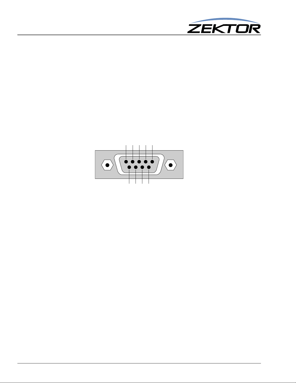
The RS-232 port is a female type DE-9 connector (sometimes mistakenly referred to as a DB-9 connector) with the following pinout:
Pin definitions:
1 - No Connect 6 - No Connect
2 - TX 7 - No Connect
3 - RX 8 - No Connect
4 - No Connect 9 - No Connect
5 - GND
Port settings used by the ClarityAudio:
Baudrate: 19200
Data Bits: 8
Stop Bits: 1
Parity: NONE
Timing information:
Min character to character time: 0ms
Min line to line time: 0ms
Min time between commands: 0ms
Max time to respond to a request: 100ms (unless otherwise specified)
4
ClarityAudio Serial Protocol, Version 1.01, 11/8/12
Page 7

Command Syntax
Command Syntax
The ClarityAudio serial command set uses an ASCII based protocol and a terminal emulator can be
used to test the serial port of the ClarityAudio.
Each serial command is formatted as:
^CMD param1,param2,...$
Where:
^ = All commands and responses start with the ‘^’ character.
CMD = The name of the command.
param = Any number of parameters can follow a command.
$ = All commands and responses end with the ‘$’ character.
For instance the name of the command to turn power on / off is ‘P’ (must be capitalized) therefore, to
turn on the ClarityAudio send:
^P 1$ -> Command sent to the A/V switch
^+$ <- Acknowledgment indicating valid command
^=P 1$ <- Response from the A/Vswitch for new setting
Command Syntax
to turn off the ClarityAudio send:
^P 0$ -> Command sent to the A/V switch
^+$ <- Acknowledgment indicating valid command
^=P 0$ <- Response from the A/V switch for new setting
NOTE: Only the characters between ‘^’ and ‘$’ are valid, any characters sent before the ‘^’ or after the ‘$’
will be ignored.
NOTE: By default, the ClarityAudio adds a carriage return and a line feed to the end of its responses, after
the ‘$’. This makes testing with terminal software easier. Since they are outside the ‘^’ and ‘$’ char
acters, they should be ignored by software drivers. If desired, this behavior can be disabled. (See:
“‘XS’ Control Settings” on page 30)
Command Responses
Type of Responses and Timing Information
There are three different types of responses: Acknowledgements, Errors and Query Strings.
By default, the ClarityAudio will always respond to a command, there are no “time-out” modes, if you
send a command and don’t get a response within 100ms, something’s wrong with the connection.
The Acknowledgement Response
Every command will be followed by an acknowledgement or error response.
-
Anytime you issue a command and there are no errors, you will receive the acknowledgement
response. Which is:
^+$
ClarityAudio Serial Protocol, Version 1.01, 11/8/12
5
Page 8

Command Syntax
The Error Response
Every command will be followed by an acknowledgement or error response.
If something is wrong with the command, you will get an error response. Which is
^!<error_number>$
which is the ‘!’ followed by an error number (in ASCII), followed the ‘$’ character.
For instance ‘2’ is not allowed as a parameter in the ‘P’ (power) command, so:
^P 2$ -> Command sent to A/V switch
^!2$ <- Error response to an out of range parameter
which indicates there was an out of range parameter.
The following are the Error Response codes that can be returned by the ClarityAudio:
1 - Unrecognized command.
2 - A parameter was out of range.
3 - Syntax error, or a badly formed command.
5 - Too many or too few parameters.
6 - Device busy, cannot process command.
7 - Buffer overflow.
8 - Command not valid if device is not powered on.
100 - DSP Programmed successfully (not really an error).
101 - 108 Error intiatializing the audio subsystem.
And some more detailed descriptions of their meanings:
Error 1 - The command given was not recognized as a ClarityAudio command. Commands are case
sensitive and in the ClarityAudio, all commands are upper case.
Error 2 - One of the parameters given was too large, or too small, the command will be ignored.
Error 3 - Something was wrong with the command's syntax. There was possibly extra data at the end
of the line, or non-decimal data as part of a parameter.
Error 5 - The number of parameters given does not match the number allowed by this command.
Error 6 - To prevent conflicts between the front panel Setup Mode and the serial port settings, when
the ClarityAudio is in the Setup Mode, many parameters become read only and any attempt at
writing them will return Error 6. Issuing the “Key Emulation” command with key code ‘0’ can
be used to exit the Setup Mode, at which point the command can be re-issued without an Error
6 response.
Error 7 - An internal buffer has overflowed.
Error 8 - Power to the device must be ‘ON’ before this command is allowed.
Error 100 - Indicates that the DSP has programmed properly. This is not really an error, but an infor-
mative message indicating the power on sequence is proceeding properly.
Error 101 - 108 - Could not communicate with the DSP subsystems.
The Query Response
The query response is sent by the ClarityAudio to indicate a setting has changed, or as a response to a
query command. The query response string consists of the ‘=’ character followed by the command
string of the command being queried.
6
For instance, in the case of the power command:
ClarityAudio Serial Protocol, Version 1.01, 11/8/12
Page 9

^P ?$ -> Send a power request command to the A/V switch
^+$ <- Acknowledgement (the command has no errors)
^=P 1$ <- Query response indicating the power is on.
Using Bitmapped Parameters
Reading / Writing Bitmapped Parameters
Some commands accept “Bitmapped” parameters. These are decimal values that represent a series of
flags, or bits, that control, enable and/or disable different device operations.
Binary arithmetic is used to represent bitmapped parameters, it is assumed the reader has some familiarity with binary arithmetic.
An example of a command that uses a bitmapped parameter is the “XS settings” command, which is
defined as:
^XS settings$
Where ‘settings’ is a bitmapped parameter defined as:
Command Syntax
Valu e
Bit Position
Name
Default:
32768 16384 8192 4069 2048 1024 512 256 128 64 32 16 8 4 2 1
15 14 13 12 11 10 9 8 7 6 5 4 3 2 1 0
0 0 AUT 0 0 0 0 0 0 0 0 CRE CHM ECO ACK ASY
0 0 1 0 0 0 0 0 0 0 0 1 0 1 1 1
For information on what each bit of the XS command does, see: “‘XS’ Control Settings” on page 30.
The “Value” row, in the table’s header, refers to the values, that when added together, create the deci-
mal parameter used by the command. For instances if you want the bits ‘ASY’ and ‘AUT’ to be set to
1, and the rest of the bits set to zero, the parameter’s value would be calculated as: 1+8192, making the
parameter value: 8193.
The command to set those two bits to ones, and reset all the others would be:
^XS 8193$
Individual bits of a bitmapped parameter can be set or reset without affecting the other bits, by prefixing the bitmapped parameter with a ‘+’ to set individual bits, or a ‘-’ to reset individual bits.
For instance in the above example the bitmapped value has been set to 8193. If we would now like to
enable the command echoing, by setting the ‘ECO’ bit, the following command can be issued:
^XS +2$
The will set the ‘IRJ’ bit, and have no affect on the others, and the new “XS” value would b e: 8195
If we’d like to now use classic mode by reseting the ‘AUT’ flag we could send:
^XS -8192$
leaving the new “XS” value to be: 3.
This command only sets and resets bits, for instance if you issue another:
^XS -8192$
the resulting “XS” value will still be ‘3’, since this bit was not set to begin with, nothing has changed.
ClarityAudio Serial Protocol, Version 1.01, 11/8/12
7
Page 10

Basic Control
Basic Control
Reference for Basic Control Commands
These commands are all that are needed for basic control of the ClarityAudio and includes power on/
off, remapping sources to zones. This section also includes some helpful control options for changing
the way serial commands behave.
Definitions
The following terms are used through out this manual.
Zone
An output. There are 16 zones on the ClarityAudio. A single zone consists of the combination of an
analog (L/R stereo) channel and a digital (SPDIF) channel. For most commands, zones are indicated
by using a ‘
Input
An input, or source. There are 16 inputs on the ClarityAudio. Each input consists of a combination of
an analog (L/R stereo) channel and a digital (SPDIF) channel. For command lines that mix inputs with
zones, ‘inputs’ are indicated by numbers without a ‘
@’ prefix character.
@’ prefix.
Channel
A channel is an analog (L/R stereo) path, or a digital (SPDIF) path. Channels are used to control breakaway features. In the “classic” mode both channels can be switched independently of each other. (See:
“‘AUT’ Enable / Disable Auto Conversion of Analog / Digital Paths” on page 31 for more information on the “classic” mode.)
The following channels are supported by the ClarityAudio:
2 - Analog Audio Channel.
4 - Digital Audio Channel.
On a command line, a channel is indicated by a period ‘.’ followed by the channel(s) number. Channel
numbers can be combined by adding them together, for instance channel number 6 would refer to both
the Digital and Analog audio chan nels. (See:
for more information on using channels to control breakaway options.)
“‘SZ’ Set Zone(s) (input / output mappings)” on page 9
8
ClarityAudio Serial Protocol, Version 1.01, 11/8/12
Page 11

Basic Control Commands
Command Description Comments
P p Power control p=power state (0=off, 1=on, +=toggle).
SZ @z,i Set zones to inputs @z=Zone, i=Input(s) (in,+,-).
SZ.ch @z,i Set zones to inputs w/break-
aways
MZ @z,m Mute zone @z=Zone, m=Mute (0=Disabled (muted), 1=Enabled, +=Toggle).
MZ.ch @z,m Mute zones w/breakaway ch=Channel(s) (1-7), @z=Zone (1-16), m=Mute (0,1,+).
DZ @z,d Set switch delay times per
zone
DZ.ch @z,m Set switch delay times per
zone w/breakaway
Table 1: Basic Control Commands
ch=Channel(s) (1-7), @z=Zone (1-16), i=Input(s) (in,+,-)
@z=Zone, d=Delay time in milliseconds
ch=Channel(s) (2,4,6), @z=Zone (1-16), d=Delay time in milliseconds
Basic Command Definitions
‘P’ Power Control
Basic Control
Turn on / off, or toggle the power state of the ClarityAudio:
^P 0$ Turn off power
^P 1$ Turn on power
^P +$ Toggle power
^P ?$ Query for current setting
Response String:
^=P n$
Where:
n = Current power status, 0=Off, 1=On.
The ‘P’ command is an exception to the 100ms rule for response time. When the power to the ClarityAudio is applied, there is a delay while the digital audio processors are initialized. The power on
response string of ‘
^P 1$’ will not be returned until the ClarityAudio is fully powered on and ready to
accept commands. This can take a few seconds.
‘SZ’ Set Zone(s) (input / output mappings)
This is the command used to map inputs to any number of zones.
Its different forms are:
^SZ @zone,@zone,in$ Map all channels of an input, to a zone or zones.
^SZ.ch @zone,in$ Map only the selected channels of inputs to zones.
^SZ.ch @zone,+$ Sequence zones forward through inputs.
^SZ.ch @zone,-$ Sequence zones in reverse through inputs.
^SZ ?$ In polled mode, reads current settings of all logged changes.
^SZ @zone,?$ Read current settings of given zones.
^SZ.ch @zone,?$ Read current settings of the selected channels of zones.
Response Strings:
ClarityAudio Serial Protocol, Version 1.01, 11/8/12
9
Page 12

Basic Control
^=SZ @zone,in$ or,
^=SZ.ch @zone,in$
Where:
@zone = One (or more) zones to be mapped.
in = Input to map to given zone(s).
ch = Channel bitmap (Range 1-7).
‘SZ’ Examples
The ‘SZ’ command in its simplest form:
^SZ @1,@3,2$
maps the input ‘2’ to the zones ‘1’ and ‘3’. You can also map multiple zones and inputs using a single
command. For instance:
^SZ @1,2,@3,@5,7$
maps the input ‘2’ to zone ‘1’, and also maps the input ‘7’ to zones ‘3’ and ‘5’.
By appending a ‘.’ and a channel bitmap to the ‘SZ’ command, the command can also be used to
breakaway the different channels:
^SZ.2 @1,3
maps only the analog audio from input ‘3’ to zone ‘1’. The digital audio channels, on zone 1, remain
unchanged. (This assumes “classic” mode. See:
“‘AUT’ Enable / Disable Auto Conversion of Ana-
log / Digital Paths” on page 31.)
The channel (the ‘.2’ in the above example) is a bitmapped number that indicates which channel or
channels are to be affected by the command.
The ClarityAudio can operate in two dif ferent modes, the classic mode, and the auto-conversion mode.
(For more information see:
“‘AUT’ Enable / Disable Auto Conversion of Analog / Digital Paths” on
page 31.)
For the classic mode, the channels are mapped as:
2 = Analog Audio
4 = Digital Audio
For the auto-conversion mode, the channels are mapped as:
2 = Audio (both digital and analog)
By adding together the above numbers, you can switch any combination of channels without affecting
the unselected channels. (These examples are only valid in the “Classic” mode.)
For instance:
^SZ.2 @3,4$
would map only the analog from input ‘4’ to zone ‘3’.
To map both the component and digital audio channels, add the component and digital audio channel
numbers together: 5 = 4 + 1, and use that as the channel number:
10
^SZ.4 @2,@3,4$
This would map the digital audio channels from input ‘4’ to zones ‘2’ and ‘3’, leaving the analo g audio
mappings unchanged.
There are two forms of the query response string, depending upon whether any channel breakaway
options are in affect.
ClarityAudio Serial Protocol, Version 1.01, 11/8/12
Page 13

Basic Control
If digital audio, and analog audio, from input ‘3’ are all mapped to zone ‘1’, then:
^SZ @1,?$ -> Query request sent to the A/V switch
would respond with:
^+$ <- Indicates no errors in the command
^=SZ @001,003 <- All audio channels are all mapped to input 3
If instead, zone ‘1’ had digital audio from input ‘3’ mapped to it, but had analog audio from inpu t ‘4’
mapped to it, the response would have been:
^=SZ.004 @001,003 <- Digital audio from input ‘3’ mapped to zone 1
^=SZ.002 @001,004 <- Analog audio from input ‘4’ mapped to zone ‘1’
‘SZ’ Query Examples
T o make parsing the response strings easier , only one response string is sent per zone. Or, in the case of
channel breakaways, only one response string per channel is returned. The response string is sent as a
fixed length string using leading zeroes.
You can request the mapping of multiple zones, with one command, and still only one response string
per zone will be returned, for instance:
^SZ @1,@3,@4,?
could return:
^+$ <- Indicates no errors in the command
^=SZ @001,002$ <- All channels of input ‘2’ mapped to zone ‘1’
^=SZ @003,001$ <- All channels of input ‘1’ mapped to zone ‘3’
^=SZ.004 @004,007$ <- Digital audio from input ‘7’ mapped to zone ‘4’
^=SZ.002 @004,005$ <- Analog audio from input ‘5’ mapped to zone ‘4’
You can also request the mapping of channels, for instance:
^SZ.2 @2,?
could return:
^SZ.002 @002,006 <- Analog audio from input ‘6’ mapped to zone 2
only the analog audio channel’s status is returned.
If you plan on using breakaway options consistently you, you can have the ClarityAudio always send
the channel with the response string. This keeps you from having to parse two different types of
strings.
Using the ‘XS’ command to set the ‘CHN’ bit, will cause the ClarityAudio to always include the channel number. The following example demonstrates this:
^XS +4$ -> Set the CHN bit
^+$ <- Acknowledge ‘XS’ command
^=XS nnnnn$ <- Indicates the new ‘XS’ settings
^SZ @1,?$ -> Request mappings for zone 1
^+$ <- Acknowledge ‘SZ’ command
^=SZ.006 @1,4 <- All channels of input ‘4’ mapped to zone ‘1’
By setting the ‘CHN’, even though all channels on zone ‘1’ are the same, the full channel bitmap is
still returned.
ClarityAudio Serial Protocol, Version 1.01, 11/8/12
11
Page 14

Basic Control
‘MZ’ Mute Zone(s)
This is the command used to mute any number of zones. When audio is muted, the sound is turned off.
For audio muting it is highly recommend that you use the VMZ command. The MZ command can only
turn the audio off (the same as powering down audio for the given zone). The VMZ has numerous
options for dealing with audio mute, such as adjustable mute levels, and fading, that are not available
when using the MZ command.
The different forms of the MZ command are:
^MZ @zone,@zone,mute$ Mute all channels of a zone or zones.
^MZ.ch @zone,mute$ Mute only the selected channels of zones.
^MZ.ch @zone,+$ Toggle the mute setting of zones.
^MZ ?$ In polled mode, reads current settings of all logged changes.
^MZ @zone,?$ Read current settings of given zones.
^MZ.ch @zone,?$ Read current settings of the selected channels of zones.
Response Strings:
^=MZ @zone,mute$ or,
^=MZ.ch @zone,mute$
Where:
@zone = One (or more) zones to be mapped.
mute = Mute setting (0=Unmuted, 1=Muted).
ch = Channel bitmap (Range 1-7).
‘MZ’ Examples
For examples on using the ‘MZ’ and how to use breakaway options, see the ‘SZ’ command.
‘DZ’ Set Zone Switching Delays
This command is used to add a “mute time” when switching between inputs.
With no delay in place, when the ClarityAudio switches from one input to another, the switching is
immediate. When a delay is added, an extra step takes place when switching between inputs.
Instead of immediately switching to the new input, the zone is first muted for the ‘delay’ amount of
time, and is then switched to the new input.
For audio devices, the sound is first muted for the amount of time given by the ‘DZ’ command, and
then switched to the new input. This can eliminated pops on some digital audio receivers.
Each channel, on each zone, can have its own delay setting (digital audio can have a different delay
than analog audio).
The different command forms are:
^DZ @zone,@zone,delay$ Add a delay to all channels of a zone or zones.
^DZ.ch @zone,delay$ Add a delay to only the selected channels of zones.
^DZ ?$ In polled mode, reads current settings of all logged changes.
^DZ @zone,?$ Read current settings of given zones.
^DZ.ch @zone,?$ Read current settings of the selected channels of zones.
12
Response Strings:
^=DZ @zone,delay$ or,
^=DZ.ch @zone,delay$
ClarityAudio Serial Protocol, Version 1.01, 11/8/12
Page 15

Where:
@zone = One (or more) zones to be mapped.
delay = The delay time in milliseconds (1000 milliseconds = 1 second).
ch = Channel bitmap (Range 1-7).
‘DZ’ Examples
For examples on using the ‘DZ’ and how to use breakaway options, see the ‘SZ’ command.
Basic Control
ClarityAudio Serial Protocol, Version 1.01, 11/8/12
13
Page 16

Audio Control
Audio Control
Reference for Audio Control Commands
The commands are used to control the audio features of the ClarityAudio.
Audio features include: Volume, Bass and Treble controls, and a 5 Band Equalizer for each zone.
Audio Control Commands
Command Description Comments
MV v Master volume v=Overall volume of all channels (0-248, 0=Full mute, 248=full volume)
VZ @z,v Per zone volume s ettings z=Zone, v=Volume level (0-200, 0=Full mute, 248=full volume)
VPZ @z,v Per zone volume as a percentage z=Zone, v=Volume percentage level (0-100, 0=Full mute, 100=full volume)
VMIZ @z,vmin Per zone minimum volume z=Zone, vmin=Minimum volume level allowed.
VMAZ @z,vmax Per zone maximum volume z=Zone, vmax=Maximum volume level allowed.
VRT timed,speed Set fade times and speeds time=Time setting when doing timed fades, speed=Speed setting when doing speed fades.
BLZ @z,b Per zone balance settings z=Zone, b=Balance setting (200=Centered, 0=Max left, 400=Max right)
BAZ @z,b Per zone bass settings z=Zone, b=Bass level (88-168, 128=0dB, 88=-20dB, 168=+20dB)
GAZ @z,g Per zone gain setting z=Zone, g=Gain (152-248, 152=-24dB, 200=0dB, 248=+24dB)
TRZ @z,t Per zone treble settings z=Zone, b=Treble level (88-168, 128=0dB, 88=-20dB, 168=+20dB)
EQ1Z @z,e Per zone band-1 equalizer settings z=Zone, e=EQ 100Hz level (88-168, 128=0dB, 88=-20dB, 168=+20dB)
EQ2Z @z,e Per zone band-2 equalizer settings z=Zone, e=EQ 330Hz level (88-168, 128=0dB, 88=-20dB, 168=+20dB)
EQ3Z @z,e Per zone band-3 equalizer settings z=Zone, e=EQ 1000Hz level (88-168, 128=0dB, 88=-20dB, 168=+20dB)
EQ4Z @z,e Per zone band-4 equalizer settings z=Zone, e=EQ 3300Hz level (88-168, 128=0dB, 88=-20dB, 168=+20dB)
EQ5Z @z,e Per zone band-5 equalizer settings z=Zone, e=EQ 10000Hz level (88-168, 128=0dB, 88=-20dB, 168=+20dB)
MXZ @z,mix Per zone stereo mixer z=Zone, mix=Mixer setting (0=Norm, 1=L/R Swap, 2=Mono, 3+=See text)
DRZ @z,routing Per zone Non-PCM routing control z=Zone,routing=Routing control (0=Pass Non-PCM digital audio, 1=Use analog audio)
LSZ @z,dly Per zone lip sync delay z=Zone, dly=Lip sync delay (0-8191, 0=no delay, 8191=170.65mS delay)
LSI @i,dly Per input lip sync delay i=Input, dly=Lip sync delay (0-8191, 0=no delay, 8191=170.65mS delay)
GAI @in.ch,gain Per input gain settings i=Input, .ch=Channel (2=Analog, 4=Digital), g=Gain (0-248, 200=0dB, 248=+24dB)
Table 2: Audio Control Commands
Audio Command Definitions
‘MV’ Set Master Volume
This command controls the overall volume of the ClarityAudio. It can be used to mute all zone (by setting it to ‘000’), or increase the overall gain of the ClarityAudio, by setting it beyond 200 (0dB).
When set to 0dB (when the volume parameter is set to 200), the Master Volume has no effect on the
audio path. Values above 0dB add gain to the overall audio levels, and levels below 0dB lower the
gain.
Volume gain is set in 0.5dB steps.
Command format:
^MV vol Set the overall volume of the A/V switch.
14
ClarityAudio Serial Protocol, Version 1.01, 11/8/12
Page 17

Response Strings:
^=MV vol$
Where:
vol = Volume in 0.5dB steps with an offset of 200. Range is 0 to 248.
The volume command is given in 0.5dB steps and uses an offset of 200 to indicate a attenuation of
0.0dB, 199 indicates 0.5dB of attenuation, and so forth, all way down to 1, which indicates an attenua
tion of 99.5dB (or a gain of -99.5dB, depending on how you look at things).
The value 0 is special in that it indicates full attenuation, or fully muted audio (-115dB).
‘VZ’ Set Zone’s Volume
Each zone has a volume level that can be set from 0dB attenuation (full volume), to -99.5dB attenuation, with a value of -100dB representing a full (more than -115dB) of mute.
There are three different ways of adjusting the volume:
1 Jump immediately to the new volume.
2 Fade to the new level in the time given by the ‘VRT’ command.
3 Fade to the new level using the slope given by the ‘VRT’ command.
(See “‘VRT’ Set Volume Ramp (Fade) Times” on page 19)
Audio Control
-
To fade to a new level over a given period of time, add 10000 to any volume command.
To fade to a new level at a given ramp speed, add 20000 to any volume command.
For a better explanation, see the examples that follow.
Volume gain is set in 0.5dB steps.
The format used to jump immediately to a new level is:
^VZ @zone,@zone,vol Set the volume of a zone or zones.
^VZ @zone,+step$ Add ‘step’ number of 0.5dB steps to current volume.
^VZ @zone,-step$ Subtract ‘step’ number of 0.5dB steps from current volume.
^VZ ?$ In polled mode, reads current settings of all volume changes.
^VZ @zone,@zone,?$ Read current volume settings of given zone(s).
Response Strings:
^=VZ @zone,vol$
Where:
@zone = One (or more) zones to be affected.
vol = Volume in 0.5dB steps with an offset of 200.
To jump immediatly to a new volume, the range is 0 to 248.
To fade to a new level in a given time period the range is 10000 to 10248.
To fade to a new level at a given speed the range is 20000 to 20248.
The volume command is given in 0.5dB steps and uses an offset of 200 to indicate a attenuation of
0.0dB, 199 indicates 0.5dB of attenuation, and so forth, all way down to 1, which indicates a gain of -
99.5dB (or an attenuation of 99.5dB, depending on how yo u look at things).
Using the ‘+’ or ‘-’ modifiers to adjust the current volume level will disable the mute command.
“‘VMZ’ Mute a Zone using Volume Control” on page 19.) The current volume level used will
(See
be the value heard by the user (volume - mute attenutation). In other words, when adjusting the volume
using +/- values, the volume will go up or down from the current value being heard by the user, regard
ClarityAudio Serial Protocol, Version 1.01, 11/8/12
-
15
Page 18

Audio Control
less of the mute setting. The mute setting will be cancelled (unmuted), but will not have an affect on
the volume level. The VMZ response will be sent to the controller to indicate mute was cancelled,
along with the VZ response to indicate the new unmuted volume level.
Setting the volume without using the ‘+’ or ‘-’ modifiers will not have an affect on the mute setting.
When setting, raising or lowering the volume, the ‘VZ’ command will not allow you to go above
‘maxVol’ setting (See
setting (See “‘VMIZ’ Set Zone’s Minimum Volume” on page 17), with an exception of ‘0’, which is
always allowed).
The value 0 is special in that it indicates full attenuation, or fully muted audio.
The value returned from the VZ command will always be in the 0-248 range, regardless of the fade set-
tings. For instance if you set the volume to ‘10200’ (fade to 200 over time), the value returned will be
200, not 10200.
‘VZ’ Examples
The ‘VZ’ command in its simplest form:
^VZ @1,200$
causes the audio on zone ‘1’ to be set to the level ‘200’, which is full volume.
The easiest way to use the volume on the ClarityAudio is to know that 200 is full volume, and 0 is off,
and everything step from 0 to 200 makes the audio louder by 0.5dB.
“‘VMAZ’ Set Zone’s Maximum Volume” on page 18), or below the ‘minVol’
(Or perhaps an even easier way is to use the VPZ command instead of the VZ command. The VPZ command allows the volume to be set using a number be tween 0 and 100 regardless of the minimum and
maximum volume settings. See
If you really need to set the volume in actual dBs, you can adjust to an absolute volume, in decibels, by
taking the gain in decibels, multiply by 2 (to account for 0.5dB steps), add 200 and use that as the vol
ume level.
For instance if you wanted to attenuate the audio by 24dB (the output level would be 24dB lower than
the input level), you take the gain of -24dB, multiply by 2, and add 200. So ‘vol = -24*2 + 200 = 152’,
and:
^VZ @1,152 -> Set the volume on zone 1 to -24.0dB
would set the volume gain on zone 1 to -24.0dB.
You can also easily add or subtract from the current volume in 0.5dB steps, for instance:
^VZ @1,+6 -> Increase the volume (make it louder) on zone 1 by 3.0dB
^VZ @3,-9 -> Decrease the volume (make it softer) on zone 3 by 4.5dB
‘VZ’ Volume Fading Examples
The ClarityAudio volume can also be faded to new levels using a timed approach, or a dB per second
approach.
To fade to a new level in a given amount of time add 10000 to the volume setting (use the VRT com-
mand to set both volume fade time and/or fade speed. See “‘VRT’ Set Volume Ramp (Fade) Times”
on page 19). For instance, if the ramp time given to the VRT command is 20 (2 seconds) then:
“‘VPZ’ Set Zone’s Volume as a Percentage” on page 18)
-
16
^VZ @1,@2,1020$
ClarityAudio Serial Protocol, Version 1.01, 11/8/12
Page 19

will fade zones 1 and 2 to the a level of 20. Regardless of their current values, zones 1 and 2 will both
reach level 20 at exactly the same time. If one zone is farther away from 20 than the other, the fade
speed will be faster, so that both zones reach the new level at the same time.
To fade to a new level using a fixed fade speed, add 20000 to the volume setting. For instance if the
ramp speed given to the VRT command is 40 (20dB per second) then:
^VZ @1,@2,20010$
will fade zones 1 and 2 to the level of 10 at a speed of 20dB per second. The zone closest to 10 will be
the first zone to reach 10.
You can cross-fade, and mix the different types of fades in a single command. For instance:
^VZ @1,10000,@2,+20040,@3,35$
will fade zone 1 to the mute level of 0, using a timed ramp. At the same time zone 2 will fade up 20dB
(40 steps) using a fixed ramp speed, and zone 3 will jump immediately to level 35.
All fades are interruptable. If you issue a new volume command while a zone is in the process of fading, it will simply begin fading to the new level from its current mid-fade setting.
‘VMIZ’ Set Zone’s Minimum Volume
Each zone has a minimum and maximum volume setting.
Audio Control
The maximum prevents a user from overdriving the speakers, amplifier, or even the ClarityAudio
switch.
The minimum allows you to set the volume to just below the noise level of a quiet room. The volume
setting ClarityAudio can be adjusted down to -99.5dB before muting. This is usually quite a bit beyond
the noise level of any room, or the noise level of most amplifiers. Since adjusting the volume below the
noise level is just a waste of time, the minimum level allows you to limit the volume range.
Attempting to set the volume below the minimum level will cause the ClarityAudio go into full mute
(no sound). When adjusting the volume upward from full mute, the volume will immediately jump to
the minimum level.
The level is set in 0.5dB steps.
Command format:
^VMIZ @zone,@zone,minVol Set the minimum volume of a zone or zones.
^VMIZ @zone,+step$ Add ‘step’ number of 0.5dB steps to current minimum.
^VMIZ @zone,-step$ Sub ‘step’ number of 0.5dB steps from current minimum.
^VMIZ ?$ In polled mode, reads current settings of all changes.
^VMIZ @zone,@zone,?$ Read current minimum setting(s) of given zone(s).
Response Strings:
^=VMIZ @zone,minvol$
Where:
@zone = One (or more) zones to be affected.
minVol = Minimum volume in 0.5dB steps with an offset of 200. Range is 0 to ‘maxVol’-99.
The gain command is given in 0.5dB steps and uses an offset of 200 to indicate a gain of 0.0d B. Values
above 200 raise gain, and values below 200 lower gain.
The minimum and maximum volume settings must have at least a 49.5dB (99 steps) difference
between them. Any attempt to set the minimum volume closer than 99 steps of the maximum, will
result in a setting of exactly 99 steps below the maximum volume setting.
ClarityAudio Serial Protocol, Version 1.01, 11/8/12
17
Page 20

Audio Control
‘VMAZ’ Set Zone’s Maximum Volume
Each zone has a minimum and maximum volume setting.
The maximum prevents a user from overdriving the speakers, amplifier, or even the ClarityAudio
switch.
The level is set in 0.5dB steps.
Command format:
^VMAZ @zone,@zone,maxVol Set the minimum volume of a zone or zones.
^VMAZ @zone,+step$ Add ‘step’ number of 0.5dB steps to current minimum.
^VMAZ @zone,-step$ Sub ‘step’ number of 0.5dB steps from current minimum.
^VMAZ ?$ In polled mode, reads current settings of all changes.
^VMAZ @zone,@zone,?$ Read current minimum setting(s) of given zone(s).
Response Strings:
^=VMAZ @zone,minvol$
Where:
@zone = One (or more) zones to be affected.
maxVol = Minimum volume in 0.5dB steps with an offset of 200. Range is ‘minVol’+99 - 248.
The gain command is given in 0.5dB steps and uses an offset of 200 to indicate a gain of 0.0d B. Values
above 200 raise gain, and values below 200 lower gain.
The minimum and maximum volume settings must have at least a 49.5dB (99 steps) difference
between them. Any attempt to set the maximum volume closer than 99 steps of the minimum, will
result in a setting of exactly 99 steps above the minimum volume setting.
‘VPZ’ Set Zone’s Volume as a Percentage
The ClarityAudio can have their volumes adjusted as a percentage instead of an dB level. This can
make writing drivers easier for many systems.
The VPZ command always uses a setting of 0 to 100, regardless of the minimum volume settings
“‘VMIZ’ Set Zone’s Minimum Volume” on page 17) and the maximum volume settings (“‘VMAZ’
(
Set Zone’s Maximum Volume” on page 18).
A value of 0 is always full mute.
A value of 1 is always the minimum volume level.
A value of 100 is always the maximum volume level.
Any value between 1 and 100 will be a percentage between minimum and maximum volume, to the
nearest 0.5dB.
The format is:
^VPZ @zone,@zone,vol Set the volume of a zone or zones.
^VPZ @zone,+step$ Add ‘step’ number of 0.5dB steps to current volume.
^VPZ @zone,-step$ Subtract ‘step’ number of 0.5dB steps from current volume.
18
^VPZ ?$ In polled mode, reads current settings of all volume changes.
^VPZ @zone,@zone,?$ Read current volume settings of given zone(s).
Response Strings:
ClarityAudio Serial Protocol, Version 1.01, 11/8/12
Page 21

Audio Control
^=VPZ @zone,vol$
Where:
@zone = One (or more) zones to be affected.
vol = Volume as a percentage: 0 through 100.
To jump immediately to a new volume, the range is 0 to 100.
To fade to a new level in a given time period the range is 10000 to 10100.
To fade to a new level at a given speed the range is 20000 to 20100.
Using the ‘+’ or ‘-’ modifiers to adjust the current volume level will disable the mute command.
“‘VMZ’ Mute a Zone using Volume Control” on page 19.) The current volume level used will
(See
be the value heard by the user (volume - mute attenutation). In other words, when adjusting the volume
using +/- values, the volume will go up or down from the current value being heard by the user, regard
less of the mute setting. The mute setting will be cancelled (unmuted), but will not have an affect on
the volume level. The VMZ response will be sent to the controller to indicate mute was cancelled,
along with the VPZ response to indicate the new unmuted volume level.
Setting the volume without using the ‘+’ or ‘-’ modifiers will not have an affect on the mute setting.
All the examples given in the set volume command (See “‘VZ’ Set Zone’s Volume” on page 15)
apply for the VPZ command as well. Simply substitute the VPZ for the VZ command and use values
between 0 and 100.
-
‘VRT’ Set Volume Ramp (Fade) Times
The ClarityAudio allows the volume to be ramped over time (fading), this command sets the ramp time
and ramp speed used when fading volume. All zones share the same times.
There are two different ways to fade volume.
1 Fade vo lume over a set period of time.
2 Fade volume at a controlled ramp speed.
The VR T allows setting both of these.
The 1st parameter of the VRT command is the ‘ramp time’ setting. This indicate the amount of time
needed to ramp (or fade) from one volume to the next and is given in 1/10th of seconds. The setting of
10 would equal 1 second. This is the value used when 10000 is added to a volume command setting.
The 2nd parameter is the ‘ramp speed’ setting. This is given in 0.5dB steps per second. The setting of
40 would equal a 20dB per second ramp speed. This is the value used when 20000 is added to a vol
ume command setting.
The VRT command format is:
^VRT time,speed$ Set the ramp time, and ramp speed.
^VRT ?$ Reads current settings.
Response Strings:
^=VRT @time,speed$
-
Where:
time = Volume ramp time in 1/10th increments. 1 = 0.1 second, 10 = 1 second, etc.
speed = Volume ramp speed in 0.5dB per second increments. 40 = 20dB per second ramp.
‘VMZ’ Mute a Zone using Volume Control
ClarityAudio Serial Protocol, Version 1.01, 11/8/12
19
Page 22

Audio Control
The VMZ command allows you to mute the volume on the ClarityAudio using the audio processor.
This differs from the MZ command which is used to completely shut down a zone.
Using the audio processor allows a mute attenuation setting; allowing you to mute a level by a specific
amount, -20dB for instance instead of full audio off.
Also available are mute fade options. Instead of instantly jumping to a mute setting, you can fade over
time, or fade at a given speed, to the new mute level.
The VMZ command is used to mute and unmute a zones. The mute level and fading options are set by
the VMLZ command (See
set using the VMT command (See “‘VMT’ Set Muting (Fade) Times” on page 21).
There are three options when using mute:
0=Unmute - This disables muting, and returns the volume back to its original unmuted level.
1=Mute - This enables muting. It attenuates the volume by the mute level (See: VMLZ).
2=NoMute - This disables muting, but sets the volume level to the current muted level.
The ‘2’ (NoMute) option allows the mute setting to be cancelled without affecting the volume level.
Response strings for the ‘VZ’ and ‘VPZ’ commands will be sent to indicate the new volume to the
controller. The response string for the ‘VMZ’ command will be a ‘0’ to indicate muting is now dis
abled. A ‘2’ will never be returned in the response string.
The VMZ command format is:
“‘VMLZ’ Set a Zone’s Mute Level” on page 20). The mute fade times are
-
^VMZ @zone,@zone,mute$ Mute all channels of a zone or zones.
^VMZ ?$ In polled mode, reads current settings of all logged changes.
^VMZ @zone,?$ Read current settings of given zones.
Response Strings:
^=VMZ @zone,mute$
Where:
@zone = One (or more) zones to be mapped.
mute = Mute setting (0=Unmuted, 1=Muted, 2=NoMute).
A value of ‘2’ is never returned by the response string. If muting is disabled by the ‘2’ (NoMute) command, a value of ‘0’ will be returned to indicate muting is disabled.
‘VMLZ’ Set a Zone’s Mute Level
The VMZ command allows you to mute the volume on the ClarityAudio. This differs from the MZ
command in that the MZ command is used to completely shut down a zone, whereas using the VMZ is
a volume based mute and allows all the volume features supported by the ClarityAudio.
These features include a mute level setting that allows you to mute a level by a specific amount, -20dB
for instance instead of a full mute.
The VMLZ setting is the value to be subtracted from the current volume when the mute command is
enabled. This value is the number of 0.5dB steps to be subtracted, for instance a setting of 40 would
subtract 20dB whenever the mute command is enabled. A setting of 248 will always do a full mute.
20
There are three different ways of muting the volume:
1 Jump immediately to the new mute volume.
2 Fade to the new level in the time given by the ‘VMT’ command.
3 Fade to the new level using the slope given by the ‘VMT’ command.
ClarityAudio Serial Protocol, Version 1.01, 11/8/12
Page 23

Audio Control
To fade to a new level over a given period of time, add 10000 to any mute level setting.
To fade to a new level at a given ramp speed, add 20000 to any mute level setting.
The format used to jump immediately to a new level is:
^VMLZ @zone,@zone,attn Set the mute attenuation of a zone or zones.
^VMLZ @zone,+step$ Add ‘step’ number of 0.5dB steps to current setting.
^VMLZ @zone,-step$ Subtract ‘step’ number of 0.5dB steps from current setting.
^VMLZ ?$ In polled mode, reads current settings of all changes.
^VMLZ @zone,@zone,?$ Read current settings of given zone(s).
Response Strings:
^=VMLZ @zone,vol$
Where:
@zone = One (or more) zones to be affected.
attn = Mute attenuation in 0.5dB steps.
To jump immediately to a new mute volume, the range is 0 to 248.
To fade to a new level in a given time period the range is 10000 to 10248.
To fade to a new level at a given speed the range is 20000 to 20248.
‘VMT’ Set Muting (Fade) Times
The ClarityAudio allows the mute command to be ramped over time (fading), this command sets the
ramp time and ramp speed used when muting volume. All zones share the same times.
There are two different ways to fade volume while muting.
1 Mute volume over a set period of time.
2 Mute volume at a controlled ramp speed.
The VMT allows setting both of these.
The 1st parameter of the VMT command is the ‘ramp time’ setting. This indicate the amount of time
needed to ramp (or fade) from one volume to the next and is given in 1/10th of seconds. The setting of
10 would equal 1 second. This is the value used when 10000 is added to the VMLZ command setting
“‘VMLZ’ Set a Zone’s Mute Level” on page 20).
(See
The 2nd parameter is the ‘ramp speed’ setting. This is given in 0.5dB steps per second. The setting of
40 would equal a 20dB per second ramp speed. This is the value used when 20000 is added to a the
VMLZ command setting.
The VMT command format is:
^VMT time,speed$ Set the ramp time, and ramp speed.
^VMT ?$ Reads current settings.
Response Strings:
^=VMT @time,speed$
Where:
time = Volume ramp time in 1/10th increments. 1 = 0.1 second, 10 = 1 second, etc.
speed = Volume ramp speed in 0.5dB per second increments. 40 = 20dB per second ramp.
‘BLZ’ Set Zone’s Balance
ClarityAudio Serial Protocol, Version 1.01, 11/8/12
21
Page 24

Audio Control
Each zone has a balance level that can be set from 0 attenuation (full left), to 400 (full right).
Balance is set in 0.5dB steps.
Command format:
^BLZ @zone,@zone,bal Set the balance of a zone or zones.
^BLZ @zone,+step$ Add ‘step’ number of 0.5dB steps to current balance.
^BLZ @zone,-step$ Subtract ‘step’ number of 0.5dB steps from current balance.
^BLZ ?$ In polled mode, reads current settings of all balance changes.
^BLZ @zone,@zone,?$ Read current balance settings of given zone(s).
Response Strings:
^=BLZ @zone,bal$
Where:
@zone = One (or more) zones to be affected.
bal = Balance in 0.5dB steps from left to right, 200=Center. Range is 0 to 400.
The balance command is given in 0.5dB steps and uses an offset of 200 to indicate center, 0 indicates
full left (no audio on right channel), 400 indicates full right (no audio on left channel).
The balance command does not add gain, it only attenuates. Moving the balance to the left will lower
the volume on the right channel, but does not increase the volume on the left channel.
The value 200 is “center” and allows audio to pass unaffected on both left and right channels.
‘GAZ’ Set Zone’s Gain (Output Levels)
Each zone has a gain level that can be set from -24dB to +24dB. The gain control allows you to match
the volume levels of each zone to the sensitivity of the amplifiers used in each zone. This allows vol
ume settings to sound the same for each zone, even when using different model/brand of amplifiers or
different model/brand of speakers.
Zone gain is set in 0.5dB steps.
Command format:
^GAZ @zone,@zone,gain Set the gain of a zone or zones.
^GAZ @zone,+step$ Add ‘step’ number of 0.5dB steps to current gain.
^GAZ @zone,-step$ Subtract ‘step’ number of 0.5dB steps from current gain.
^GAZ ?$ In polled mode, reads current settings of all gain changes.
^GAZ @zone,@zone,?$ Read current gain settings of given zone(s).
Response Strings:
^=GAZ @zone,gain$
Where:
@zone = One (or more) zones to be affected.
gain = Gain in 0.5dB steps with an offset of 200. Range is 152 to 248.
-
The gain command is given in 0.5dB steps and uses an offset of 200 to indicate a gain of 0.0d B. Values
above 200 raise gain, and values below 200 lower gain.
‘GAI’ Set Input’s Gain (Input Trimming)
22
ClarityAudio Serial Protocol, Version 1.01, 11/8/12
Page 25

Audio Control
Each input has a gain level that can be set from -24dB to +24dB. The gain control allows you to match
the volume levels of each input to the different levels of each source. This allows volume settings to
sound the same, when switching between source devices with different output levels.
Input gain is set in 0.5dB steps.
Command format:
^GAI @input,@input,gain Set the gain of a input or inputs.
^GAI @input,+step$ Add ‘step’ number of 0.5dB steps to current input.
^GAI @input,-step$ Subtract ‘step’ number of 0.5dB steps from current input.
^GAI ?$ In polled mode, reads current settings of all input changes.
^GAI @input,@input,?$ Read current gain settings of given input(s).
Response Strings:
^=GAZ @input,gain$
Where:
@input = One (or more) inputs to be affected.
gain = Gain in 0.5dB steps with an offset of 200. Range is 152 to 248.
The gain command is given in 0.5dB steps and uses an offset of 200 to indicate a gain of 0.0d B. Values
above 200 raise gain, and values below 200 lower gain.
‘BAZ’, ‘TRZ’ Set Zone’s Bass and Treble Levels
Each zone has a Bass and Treble level that can range from -20.0dB to +20.0dB. Interaction between
the Bass and Treble controls and the 5 Band Equalizer settings are limited to a +/-20.0dB range. Add
ing a boost of +20.0dB to the Bass setting as well as the EQA or EQB equalizer bands, will not result
in a +40.0dB, but will be limited to +20.0dB.
The levels are set in -0.5dB steps.
Command formats:
^BAZ @zone,@zone,level Set the bass level of a zone or zones.
^BAZ @zone,+step$ Add ‘step’ number of 0.5dB steps to current bass level.
^BAZ @zone,-step$ Subtract ‘step’ number of 0.5dB steps from current level.
^BAZ ?$ In polled mode, reads current settings of all bass changes.
^BAZ @zone,@zone,?$ Read current bass level settings of given zone(s).
^TRZ @zone,@zone,level Set the treble level of a zone or zones.
^TRZ @zone,+step$ Add ‘step’ number of 0.5dB steps to current treble level.
^TRZ @zone,-step$ Subtract ‘step’ number of 0.5dB steps from current level.
^TRZ ?$ In polled mode, reads current settings of all bass changes.
^TRZ @zone,@zone,?$ Read current bass level settings of given zone(s).
Response Strings:
^=BAZ @zone,level$
^=TRZ @zone,level$
-
Where:
ClarityAudio Serial Protocol, Version 1.01, 11/8/12
23
Page 26

Audio Control
@zone = One (or more) zones to be affected.
level = Levels 0.5dB steps with offsets of 128 (128 = 0.0dB).
The levels in the commands are given in 0.5dB steps and use an offset of 128 to indicate a boost / cut
of 0.0dB. Values above 128 boost level by 0.5dB per step, for instance 129 = +0.5dB (a boost of
0.5dB), and 127 = -0.5dB (a cut of 0.5dB).
‘BAZ’ (‘TRZ’) Examples
Examples are only given for the bass command ‘BAZ’, for treble commands use ‘TRZ’ in the place of
‘BAZ. The simplest form of the command is:
^BAZ @1,128$
and causes the bass level on zone ‘1’ to be set to 0.0dB which is flat (no boost or cut).
The easiest way to use the volume on the ClarityAudio is to know that 168 is full boost, and 88 is full
cut and every step from 88 to 168 boosts the bass level by 0.5dB, with 128 used to indicate no boost or
cut.
Or you can set a zone to an absolute level, in decibels, by taking the gain (which is positive for boost
and negative for cut), multiplying by 2 (to take into account the 0.5dB steps), adding 128, and using
that as the new level.
For instance if you wanted to boost bass by 9dB, you’d take the gain: 9dB multiply by 2 and add 200.
So ‘level = 9*2 + 128 = 146’, and:
^BAZ @1,146 -> Boost bass by 9.0dB
would set the bass boost on zone 1 to 9.0dB.
You can also easily add or subtract from the current level in 0.5dB steps, for instance:
^BAZ @1,+6 -> Boost bass on zone 1 by 3.0dB
^BAZ @3,-9 -> Cut bass on zone 3 by 4.5dB
When using the ‘+’ and ‘-’ prefixes to add or subtract from current levels, the ‘BAZ’ command will
not allow you to go above 168 (+20.0dB) or below 88 (-20.0dB), though it’s perfectly valid to send a
command that would attempt this.
‘EQ1Z’, ‘EQ2Z’, ‘EQ3Z’, ‘EQ4Z’, ‘EQ5Z’ Set the 5 Band Equalizers’ levels
Each zone has a 5 Band Equalizer associated with it, each of the five bands have levels that range from
-20.0dB to +20.0dB. Interaction between the Bass and Treble controls and the 5 Band Equalizer set
tings are limited to a +/-20.0dB range. Adding a boost of +20.0dB to the Bass setting as well as the
EQA or EQB equalizer bands, will not result in a +40.0dB, but will be limited to +20.0dB.
The levels are set in -0.5dB steps.
The band center frequencies for each command are:
EQ1Z - 100Hz (and below, this is a low frequency slope filter.)
EQ2Z - 330Hz
EQ3Z - 1,000Hz
EQ4Z - 3,300Hz
EQ5Z - 10,000Hz (and above, this is a high frequency slope filter.)
-
24
Only the ‘EQ1Z’ command will be described, all the bands use identical syntax.
Command format:
^EQ1Z @zone,@zone,level Set the EQ level of a zone or zones.
^EQ1Z @zone,+step$ Add ‘step’ number of 0.5dB steps to current EQ level.
ClarityAudio Serial Protocol, Version 1.01, 11/8/12
Page 27

Audio Control
^EQ1Z @zone,-step$ Subtract ‘step’ number of 0.5dB steps from current level.
^EQ1Z ?$ In polled mode, reads current settings of all EQ changes.
^EQ1Z @zone,@zone,?$ Read current EQ level settings of given zone(s).
Response String:
^=EQ1Z @zone,level$
Where:
@zone = One (or more) zones to be affected.
level = Levels 0.5dB steps with offsets of 128 (128 = 0.0dB).
The levels in the commands are given in 0.5dB steps and use an offset of 128 to indicate a boost / cut
of 0.0dB. Values above 128 boost level by 0.5dB per step, for instance 129 = +0.5dB (a boost of
0.5dB), and 127 = -0.5dB (a cut of 0.5dB).
‘EQ1Z’ Examples
Examples are only given for the EQ band-1 command ‘EQ1Z’, for other bands, substitute the proper
command for the desired band. The simplest form of the command is:
^EQ1Z @1,128$
and causes the EQ level on zone ‘1’ to be set to 0.0dB which is flat (no boost or cut).
The easiest way to use the equalizer settings on the ClarityAudio is to know that 168 is full boost, and
88 is full cut and every step from 88 to 168 boosts the EQ level by 0.5dB, with 128 used to indicate no
boost or cut.
Or you can set a zone to an absolute level, in decibels, by taking the gain (which is positive for boost
and negative for cut), multiplying by 2 (to take into account the 0.5dB steps), adding 128, and using
that as the new level.
For instance if you wanted to boost the EQ level by 9dB, you’d take the gain: 9dB multiply by 2 and
add 200. So ‘level = 9*2 + 128 = 146’, and:
^EQ1Z @1,146 -> Boost EQ band’s level by 9.0dB
would set the EQ level on zone 1 to a 9.0dB boost.
You can also easily add or subtract from the current level in 0.5dB steps, for instance:
^EQ1Z @1,+6 -> Boost EQ band’s level on zone 1 by 3.0dB
^EQ1Z @3,-9 -> Cut EQ band’s level on zone 3 by 4.5dB
When using the ‘+’ and ‘-’ prefixes to add or subtract from current levels, the ‘EQxZ’ commands will
not allow you to go above 168 (+20.0dB) or below 88 (-20.0dB), though it’s perfectly valid to send a
command that would attempt this.
‘MXZ’ Stereo to Mono Down Mix for a Zone
Stereo audio can be mix in a number of different ways. This includes swapping channels, and a number
of ways of creating mono audio.
Command format:
^MXZ @zone,@zone,mix Set the stereo mix down of a zone or zones.
Response Strings:
^=MXZ @zone,mix$
Where:
ClarityAudio Serial Protocol, Version 1.01, 11/8/12
25
Page 28

Audio Control
@zone = One (or more) zones to be affected.
mix = Stereo mix down flag.
0 = No change to audio.
1 = Swap left and right channels.
2 = Mix to mono by adding left and right channels.
3 = Mix to mono by using the left channel for both outputs.
4 = Mix to mono by using the right channel for both outputs.
5 = Mix to mono by subtracting the right channel from the left.
6 = Mix to mono by subtracting the left channel from the right.
‘DRZ’ Non-PCM Digital audio Routing
The ClarityAudio cannot mix down non-PCM audio, this is any non-PCM stereo audio bitstream, and
includes Dolby5.1, DTS Audio, and all other types of multichannel audio.
Any time non-PCM audio is detected on a digital input, the analog audio inputs are routed to the analog outputs.
This command allows you to decide what data to send to the digital coax output when surround sound
audio (non-PCM audio) is detected on a digital input.
You can choose to send the surround sound audio as is, this assumes you have a receiver that can
decode surround sound audio, or you can choose to ignore the surround sound audio and instead, con
vert the analog audio to digital (PCM audio) and send it out the digital output.
-
This command also doubles as the source selection command when running the switch in the “Classic”
mode. In the classic mode no auto-detection is done, and this command is used to select between ana
log and digital audio sources, for each of the Coax outputs.
Command format:
^DRZ @zone,@zone,routing Set the non-PCM routing option.
Response Strings:
^=DRZ @zone,routing$
Where:
@zone = One (or more) zones to be affected.
routing = Routing flag.
0 = Non-PCM, digital audio (such as Dolby5.1) is routed, as-is, to the digital output.
1 = Analog audio is converted to digital, and routed to the digital output.
‘LSZ’ Set Lip Sync delay for a Zone
Each zone is capable of delaying audio for up to 170.65mS. The delay resolution is 1/48000 of a second, or 48 counts per millisecond.
Command format:
^LSZ @zone,@zone,delay Set the lip sync delay of a zone or zones.
^LSZ @zone,+step$ Ad d ‘step’ to zone’s delay.
^LSZ @zone,-step$ Subtract ‘step’ from zone’s delay.
-
26
Response Strings:
^=LSZ @zone,delay$
Where:
ClarityAudio Serial Protocol, Version 1.01, 11/8/12
Page 29

Audio Control
@zone = One (or more) zones to be affected.
delay = Lip sync delay in 48KHz samples, each count delays audio by 1/48000 of a second.
A value of 0 indicates no delay.
There are two forms of the lip sync delay commands, the ‘LSZ’ command which sets lip sync delay on
a zone by zone basis, and the ‘LSI’ command which sets delays on a input by input basis. Which one to
use depends on what is causing the video delay, and where it’s connected in the video path.
If the input of a video processor (or monitor) that adds a video delay is connected to a zone, then the
‘LSZ’ command should be used to delay the audio by the same amount of time the video is being
delayed. Only audio that is being sent to the video processor, attached to the zone, will be delayed.
If on the other hand, if the output of a video processor that adds a video delay , is connected to an input,
then the ‘LSI’ command should be used. This allows all zones that connect to the video processor, to
have their delays automatically adjusted to compensate for the processor’s video delays.
Both inputs and zones can have delays set, however the overall delay cannot exceed 8191 counts (or
170.65mS). If an input and zone combination exceeds 8191 counts, no error will be generated and the
delay will be set to 8191.
‘LSZ’ Examples
The lip sync delay is given in samples of a 48KHz clock, or 48 counts per millisecond. To delay the
audio by a given number of milliseconds, take the number of milliseconds, multiply by 48, and use that
as the parameter for the command. For instance to delay zone 3 by 24mS: 24mS * 48 = 1152
^LSZ @3,1152 -> Delay zone 3 by 1152 samples (24mS)
Another common timing to apply to lip sync delay is video frame times. Most video processor delay
video by a set number of frames, matching audio to video in these cases is done by delay audio by the
same number of frames. For instance 1080p60, is 60 frames per second, while 1080p24, is 24 frames
per second. To calculate the value needed to delay a set number of frame, divide the frames per second
into 48000, and multiply by the number of frames to delay. For instance if your video signal is 60
frames per second, and you want to delay zone 3 by 2 frames: (48000 / 60fps) * 2 = 1600
^LSZ @3,1600 -> Delay zone 3 by 1600 samples (two 60fps frames)
^LSZ @2,+800 -> Add one 60fps frame of delay to zone 2
‘LSI’ Set Lip Sync delay for an Input
Each input is capable of delaying audio for up to 170.65mS. The delay resolution is 1/48000 of a second, or 48 counts per millisecond.
Command format:
^LSI @in,@in,delay Set the lip sync delay an input or inputs.
^LSI @in,+step$ Add ‘step’ to input’s delay.
^LSI @in,-step$ Subtract ‘step’ from input’s delay.
Response Strings:
^=LSI @in,delay$
Where:
@in = One (or more) inputs to be affected.
delay = Lip sync delay in 48KHz samples, each count delays audio by 1/48000 of a second.
A value of 0 indicates no delay.
ClarityAudio Serial Protocol, Version 1.01, 11/8/12
27
Page 30

Audio Control
There are two forms of the lip sync delay commands, the ‘LSZ’ command which sets lip sync delay on
a zone by zone basis, and the ‘LSI’ command which sets delays on a input by input basis. Which one to
use depends on what is causing the video delay, and where it’s connected in the video path.
If the input of a video processor (or monitor) that adds a video delay is connected to a zone, then the
‘LSZ’ command should be used to delay the audio by the same amount of time the video is being
delayed. Only audio that is being sent to the video processor, attached to the zone, will be delayed.
If on the other hand, if the output of a video processor that adds a video delay , is connected to an input,
then the ‘LSI’ command should be used. This allows all zones that connect to the video processor, to
have their delays automatically adjusted to compensate for the processor’s video delays.
Both inputs and zones can have delays set, however the overall delay cannot exceed 8191 counts (or
170.65mS). If an input and zone combination exceeds 8191 counts, no error will be generated and the
delay will be set to 8191.
For examples, see the examples of the ‘LSZ’ command on page 26.
28
ClarityAudio Serial Protocol, Version 1.01, 11/8/12
Page 31

Advanced Control
Reference for Advance Control Commands
These commands are for more advanced control over the ClarityAudio.
Advanced Control Commands
Command Description Comments
V ? Get version string Returns: Product name and firmware version string.
QI ? Query for capability information Returns: Number of zones & inputs, and a full channel mask.
XS flags Control settings Set / reset control options. flags=Control option flags (see text).
SS flags Save Settings Save specified settings as initial power on values. flags=Indicates which settings to save.
FS flags Reset to factory settings Resets selected values to initial factory settings. flags=Indicates which settings to reset.
IPA xxx,xxx,xxx,xxx View or change TCP/IP address View the current IP address, or change it.
IPM xxx,xxx,xxx,xxx View or change TCP/IP mask View the current IP mask, or change it.
IPR xxx,xxx,xxx,xxx View or change TCP/IP router View the current router IP address (gateway), or change it.
Table 3: Advanced Control Commands
Advanced Control
Advanced Command Definitions
‘V’ Version
Returns the current firmware version of the ClarityAudio.
^V ?$
Response String:
^=V “CasinoAV16x16”,1.0a,30B2S12345678$
Where:
“CasinoAV16x16” = Model (varies by model)
1.10a = Firmware version
45B1S12345678 = Serial number
‘QI’ Query for Zone, Input and Channel Information
Returns the number of zones, and inputs, and a mask of the channels available on the ClarityAudio.
^QI ?$
Response String:
^=QI chan_bitmap,vinputs,vzones,ainputs,azones,dinputs,dzones$
Where:
chan_bitmap = Bitmap of the available channels
vinputs = Number of video inputs
vzones = Number of video zones
ainputs = Number of analog audio inputs
azones = Number of analog audio zones
dinputs = Number of digtial audio inputs
ClarityAudio Serial Protocol, Version 1.01, 11/8/12
29
Page 32

Advanced Control
dzones = Number of digital audio zones
‘XS’ Control Settings
Turn on and off operational modes of the ClarityAudio.
The format of the command is:
^XS settings1,settings2$ Set the control bits to ‘settings1’ and ‘settings2’
^XS +settings1,+settings2$ Set bits indicated in ‘settings1’ and ‘settings2’ to 1
^XS -settings1,+settings2$ Reset bits indicated in ‘settings1’ and ‘settings2’ to 0
^XS ?$ Query for current settings
Response String:
^=XS settings1,settings2$
Where ‘settings1’ is a bitmapped parameter defined as:
Valu e
Bit Position
Name
Default:
Valu e
Bit Position
Name
Default:
32768 16384 8192 4069 2048 1024 512 256 128 64 32 16 8 4 2 1
15 14 13 12 11 10 9 8 7 6 5 4 3 2 1 0
0 0 AUT 0 0 0 0 0 0 0 0 CRE CHM ECO ACK 0
0 0 1 0 0 0 0 0 0 0 0 1 0 1 1 1
ACK - 0=Don’t acknowledge cmds with “^+$” 1=Acknowledge error free commands with a “^+$”
ECO - 0=Do not send a response strings for each cmd. 1=Always send response string when a serial command is issued
CHM- 0=Only send a “.ch” when needed. 1=Always append a “.ch” channel mask to a zone response cmd
CRE - 0=Don’t send CRs/LFs at end of responses 1=End all responses with a carriage return and a line feed.
AUT - 0=Classic Analog/Digital mode. 1=Automatic conversion of Analog/Digital paths.
Where ‘settings2’ is a bitmapped parameter defined as:
32768 16384 8192 4069 2048 1024 512 256 128 64 32 16 8 4 2 1
15 14 13 12 11 10 9 8 7 6 5 4 3 2 1 0
0 0 0 0 0 0 0 0 0 0 0 0 0 0 MJP 0
0 0 0 0 0 0 0 0 0 0 0 0 0 0 0 0
MJP - 0=Volume increments from mute level. 1=Volume jumps to unmute level before incrementing.
All other bits are reserved and should be set to 0.
This command uses a bitmapped parameter. Each bit can set or reset without affecting the other bits.
“Using Bitmapped Parameters” on page 7, for more information on using bitmapped parame-
(See:
ters.)
Both parameters do not have to be present on the command line, if a parameter is left out the command, it will be left unchanged:
30
^XS settings1$ Only ‘settings1’ is changed
Since ‘settings2’ was not present on the command line, it will not be affected.
A comma can be used to indicate a missing parameter:
^XS ,settings2$ Only ‘settings2’ is changed
Since ‘settings1’ was not present on the command line, it will not be affected.
The following paragraphs define each option in more detail:
ClarityAudio Serial Protocol, Version 1.01, 11/8/12
Page 33

Advanced Control
‘ACK’ Enable / Disable Acknowledgements
Each time a command is sent to the ClarityAudio, the ClarityAudio responds with either an error message, if there was a problem with the command, or an acknowledgement string of “^+$”. This behavior can be changed by setting this bit to ‘0’. If the bit is reset, the “^+$” string will not be sent.
‘ECO’ Enable / Disable the ‘Parameter Changed’ Strings
Each command that makes a change to a parameter, will be echoed with a response string that indicates
the new values of the parameters changed. The response strings are only issued after the changes have
taken affect, and reflect the new state of the ClarityAudio.
With this bit set to ‘0’, these response strings will not be sent. To verify the new settings, the controller
must read the new values manually.
‘CHM’ Enable / Disable always sending“.ch” masks on zone commands
On commands that change zone settings (‘SZ’, ‘MZ’, ‘DZ’), the “.ch” channel mask is only sent when
needed to indicate a difference in settings between channel. With this bit set, the “.ch” mask will
always be sent, regardless of any differences between channel settings.
If you plan on using the ClarityAudio’s breakaway functions, setting this bit can make parsing the
response strings easier, since only one type of response string will be returned.
‘CRE’ Enable / Disable trailing Carriage Returns Line Feeds
A carriage return and line feed can be appended to all responses coming from the ClarityAudio. This is
useful when using terminal software to test command strings.
Since the carriage returns and line feeds are sent outside of the normal string (they are sent after the
ending ‘
can be turned off by setting this bit to a ‘0’.
‘AUT’ Enable / Disable Auto Conversion of Analog / Digital Paths
When this bit is set to ‘0’, the ClarityAudio behaves like a classic A/V switch, in that it maintains separate paths for the analog and digital signals. Volume and Tone controls will only affect the analog
paths. The digital signals will be routed separately, and are routed as-is, volume and tone will have no
affect on the digital signals. This also allows the digital audio to breakaway from the analog audio,
allowing the digital audio to be switched independent of the analog audio paths.
No automatic selection is done on the audio signals in the classic mode, so you must select the type of
audio that will be present at each of the Coax outputs. This is done using the ‘DRZ’ command. (See:
“‘DRZ’ Non-PCM Digital audio Routing” on page 26.)
When this bit is set to ‘1’, the ClarityAudio performs automatic conversion of the analog and digital
signals. The Volume and Tone controls will affect both the analog and digital outputs, and the inputs
will be automatically selected based on the signals present on the inputs. The selection is done on an
input by input basis, and the priorities are:
$’), they should be ignored by the controller . But if there are problems with this behavi or , they
• If no digital signal is present, the analog input will be used. The analog audio will be converted
to digital audio and be available on the digital outputs, as well as the analog outputs. Volume
and Tone settings will affect both digital and analog outputs.
• If a stereo PCM digital signal is present, the digital input will be used. The digital audio will be
converted to analog audio and be available on the analog outputs, as well as the digital outputs.
Volume and Tone settings will affect both digital and analog outputs.
• If a Dolby Digital or DTS Audio, or some other form of non PCM encoded bitstream audio is
present on the digital inputs, then the digital audio will be routed, unaffected to the digital out
ClarityAudio Serial Protocol, Version 1.01, 11/8/12
-
31
Page 34

Advanced Control
puts, and the analog audio will be routed to the analog outputs. Volume and Tone settings will
only affect the analog outputs.
• The ClarityAudio will automatically choose between the Coax and Optical inputs based on the
presence of a signal. If there are digital signals present on both the Coax and Optical inputs,
the ClarityAudio will choose the Coax input as its source.
When in the auto conversion mode, the digital paths cannot be switched independent of the analog
paths. In this mode, there is no “digital” and “analog” paths, but simply an audio path, with multiple
types of inputs and outputs.
‘SS’ Save Default Power On Settings
When all power is lost to the ClarityAudio (for instance the power cord is unplugged), the current settings will be lost. When power is restored all settings will be set to their initial values. This command
allows you to change those initial values.
T o use this command, the ClarityAudio should have there parameters to be saved, set to the values that
are to be used as the initial values.
Once the current settings are in place, this command is issued to save the current settings as the initial
values.
This command uses a bitmapped parameter to indicate which values are to be saved. A bit set to ‘1’
indicates the associated setting should be saved, a bit set to ‘0’ indicates the setting should not be saved
and the previously saved setting will remain unchanged.
Valu e
Bit
Command formats:
^SS settings$ Set the enable bits to ‘settings’
Response String:
There is no response string to the SS command, this command is write only.
Where ‘settings’ is a bitmapped parameter defined as:
32768 16384 8192 4069 2048 1024 512 256 128 64 32 16 8 4 2 1
15 14 13 12 11 10 9 8 7 6 5 4 3 2 1 0
Bit-0 - Save zone input/output mappings, and power state
Bit-1 - Save switch delay times set by the ‘DZ’ command
Bit-2 - *Reserved*
Bit-3 - Save control settings (the ‘XS’ command settings)
Bit-4 - *Reserved*
Bit-5 - Save IP parameters and settings (‘IPA’, ‘IPM’, ‘IPG’, and ‘IPSET’ settings)
Bit-6 - *Reserved*
Bit-7 - *Reserved*
Bit-8 - Save zones’ volume settings
Bit-9 - Save zones’ audio parameters (bass, treble, eq, mute level, zone gains, zone lipsync, etc. all but volume)
Bit-10 - Save source audio parameters (input gains, input lipsync delay)
Bit-11 - Save global audio parameters (master volume, volume and mute fade times)
‘FS’ Reset to Factory Settings
This command will reset selected parameters of the ClarityAudio to their factory default settings.
32
ClarityAudio Serial Protocol, Version 1.01, 11/8/12
Page 35

Advanced Control
This command uses a bitmapped parameter to indicate which values are to be reset. A bit set to ‘1’
indicates the associated setting should be reset, a bit set to ‘0’ indicates the setting should not be reset
and the previous setting will remain unchanged.
Command formats:
^FS settings$ Reset the parameters indicated by ‘settings’
Response String:
There is no response string to the FS command, this command is write only.
Where ‘settings’ is a bitmapped parameter defined as:
Valu e
Bit
32768 16384 8192 4069 2048 1024 512 256 128 64 32 16 8 4 2 1
15 14 13 12 11 10 9 8 7 6 5 4 3 2 1 0
Bit-0 - Reset zone input/output mappings, and power state
Bit-1 - Reset switch timings (the ‘DZ’ command settings)
Bit-2 - *Reserved*
Bit-3 - Reset control settings (the ‘XS’ command settings)
Bit-4 - *Reserved*
Bit-5 - Reset IP parameters
Bit-6 - *Reserved*
Bit-7 - *Reserved*
Bit-8 - Reset zones’ volume settings
Bit-9 - Reset zones’ audio parameters (bass, treble, eq, mute level, zone gains, zone lipsync, etc. all but volume)
Bit-10 - Reset source audio parameters (input gains, input lipsync delay)
Bit-11 - Reset global audio parameters (master volume, volume and mute fade times)
ClarityAudio Serial Protocol, Version 1.01, 11/8/12
33
Page 36

Advanced Control
TCP/IP Control
The ClarityAudio can use DHCP to negotiate an address with a router, or it can be programmed to use
a static IP address.
The ‘IPSET’ command is used to switch between the two modes. ‘IPSET 0’ indicates a static address,
and ‘IPSET 1’ indicates a DHCP negotiated address.
T o set a new static IP address, first issue the ‘IPA’, ‘IPM’ and ‘IPG’, commands to setup the IP address,
IP mask, and IP gateway, respectively. Then issue the ‘IPSET 0’ command.
‘IPSET’ Set the IP operation mode, DHCP or STATIC
This command is used to set the TCP/IP operating mode of the ClarityAudio. It allows you to choose
between DHCP and Static IP address operations.
When set to the DHCP, the ClarityAudio will negotiate an IP address, IP mask, and gateway address
(the address of the router), using DHCP.
When set to Static mode, the IP address, IP mask, and gateway address, given by the ‘IPA’, ‘IPM’ and
‘IPG’ commands will be used.
You can easily switch between the two modes without losing the static address setting. In other words
when switching to DHCP new IP address values will be obtained from the router, but the static IP
address values of the ‘IPA’, ‘IPM’ and ‘IPG’ commands are not lost, and when returning to static
mode, these settings do not need to be resent.
The command format is:
^IPSET mode$ Set new TCP/IP operating mode
^IPSET ?$ Read the current TCP/IP operating mode
Response String:
^=IPSET mode$
Where:
mode = Current operating mode. 0=Static, 1=DHCP.
To change the static IP address the ‘IPSET 0’ form of this command must be issued. This is true even
if you are already operating in the static mode. For instance if your static address is 192.168.1.100 and
you wish to change it to 192.168.1.101, you must first issue a ‘IPA’ command and then reissue the
‘IPSET 0’ command:
^IPA 192,168,1,101$ Set the new static address
^IPSET 0$ Tell the ClarityAudio to use the new static address
34
ClarityAudio Serial Protocol, Version 1.01, 11/8/12
Page 37

‘IPA’ Set / View the static IP Address
This command does not immediately change the TCP/IP address. It sets up the static IP address that
will be used the next time the ‘IPSET 0’ command is issued.
The command format is:
^IPA xxx,xxx,xxx,xxx$ Set new TCP/IP address
^IPA ?$ Read the current TCP/IP address
Response String:
^=IPA xxx,xxx,xxx,xxx$
Where:
xxx,xxx,xxx,xxx = IP address in standard form (Ex: 192,168,001,200)
The response string of the ‘IPA’ command is not the current IP address of the ClarityAudio, but the IP
address that will be used the next time the ‘IPSET 0’ command is issued. To retrieve the current IP
address of the ClarityAudio, use the read only command ‘IPAX’ (See:
IP address in use” on page 36.)
‘IPM’ Set / View the static IP Mask
This command does not immediately change the TCP/IP mask. It sets up the static mask that will be
used the next time the ‘IPSET 0’ command is issued..
Advanced Control
“‘IPAX’ Retrieve the current
The command format is:
^IPM xxx,xxx,xxx,xxx$ Set new TCP/IP mask
^IPM ?$ Read the current TCP/IP mask
Response String:
^=IPM xxx,xxx,xxx,xxx$
Where:
xxx,xxx,xxx,xxx = IP mask in standard form (Ex: 255,255,255,000)
The response string of the ‘IPA’ command is not the current IP mask of the ClarityAudio, but the IP
mask that will be used the next time the ‘IPSET 0’ command is issued. To retrieve the current IP mask
of the ClarityAudio, use the read only command ‘IPMX’ (See:
in use” on page 36.)
‘IPG’ Set / View the static IP gateway address
This command does not immediately change the TCP/IP gateway. It sets up the TCP/IP gateway
address that will be used the next time the ‘IPSET 0’ command is issued.
The command format is:
^IPG xxx,xxx,xxx,xxx$ Set new TCP/IP router address
^IPG ?$ Read the current TCP/IP router address
Response String:
“‘IPMX’ Retrieve the current IP mask
^=IPG xxx,xxx,xxx,xxx$
Where:
xxx,xxx,xxx,xxx = Gateway address in standard form (Ex: 192,168,001,001)
ClarityAudio Serial Protocol, Version 1.01, 11/8/12
35
Page 38

Advanced Control
The response string of the ‘IPG’ command is not the current gateway address of the ClarityAudio, but
the gateway address that will be used the next time the ‘IPSET 0’ command is issued. To retrieve the
current IP address of the ClarityAudio, use the read only command ‘IPGX’ (See:
the current IP gateway address in use” on page 36.)
‘IPAX’ Retrieve the current IP address in use
This is read only and will return the IP address being used by the ClarityAudio. If DHCP is being used,
this will return the address given to the ClarityAudio by the router. If static mode is being used, this
will return the static address currently in use by the ClarityAudio.
The command format is:
^IPAX ?$ Read the current IP address
Response String:
^=IPAX xxx,xxx,xxx,xxx$
Where:
xxx,xxx,xxx,xxx = IP address in standard form (Ex: 192,168,001,200)
‘IPMX’ Retrieve the current IP mask in use
This command is read only and will return the IP mask being used by the ClarityAudio. If DHCP is
being used, this will return the mask given to the ClarityAudio by the router. If static mode is being
used, this will return the static mask currently in use by the ClarityAudio.
“‘IPGX’ Retrieve
The command format is:
^IPGX ?$ Read the current IP mask
Response String:
^=IPGX xxx,xxx,xxx,xxx$
Where:
xxx,xxx,xxx,xxx = IP mask in standard form (Ex: 255,255,255,000)
‘IPGX’ Retrieve the current IP gateway address in use
This command is read only and will the gateway address being used by the ClarityAudio. If DHCP is
being used, this will return the address given to the ClarityAudio by the router. If static mode is being
used, this will return the static address currently in use by the ClarityAudio.
The command format is:
^IPGX ?$ Read the current TCP/IP router address
Response String:
^=IPGX xxx,xxx,xxx,xxx$
Where:
xxx,xxx,xxx,xxx = Gateway address in standard form (Ex: 192,168,001,001)
36
ClarityAudio Serial Protocol, Version 1.01, 11/8/12
 Loading...