

Page 1

Home Theater Solutions
MAS7.1
RS-232 Serial Protocol Reference
Page 2

Table of Contents
RS-232 Port Hardware . . . . . . . . . . . . . . . . . . . . . . . . . . . . . . . . . . . . . . . . . . . . . . . 3
RS-232 Pinout and Baudrate Settings. . . . . . . . . . . . . . . . . . . . . . . . . . . . . . . . . . . . . . . . . . . . . . . . . . 3
MAS7.1 Quick Reference . . . . . . . . . . . . . . . . . . . . . . . . . . . . . . . . . . . . . . . . . . . . . 4
Command Syntax . . . . . . . . . . . . . . . . . . . . . . . . . . . . . . . . . . . . . . . . . . . . . . . . . . . . . . . . . . . . . . . . . 4
Command Responses. . . . . . . . . . . . . . . . . . . . . . . . . . . . . . . . . . . . . . . . . . . . . . . . . . . . . . . . . . . . . . 4
The Acknowledgement Response . . . . . . . . . . . . . . . . . . . . . . . . . . . . . . . . . . . . . . . . . . . . . . . . . . . . . . . . . . 4
The Error Response . . . . . . . . . . . . . . . . . . . . . . . . . . . . . . . . . . . . . . . . . . . . . . . . . . . . . . . . . . . . . . . . . . . . . 4
Query Strings . . . . . . . . . . . . . . . . . . . . . . . . . . . . . . . . . . . . . . . . . . . . . . . . . . . . . . . . . . . . . . . . . . . . . . . . . . . 5
Checksums and CRC8’s . . . . . . . . . . . . . . . . . . . . . . . . . . . . . . . . . . . . . . . . . . . . . . . . . . . . . . . . . . . . 5
MAS7.1 Quick Command Reference . . . . . . . . . . . . . . . . . . . . . . . . . . . . . . . . . . . . . . . . . . . . . . . . . . 6
Table of MAS7.1 Commands . . . . . . . . . . . . . . . . . . . . . . . . . . . . . . . . . . . . . . . . . . . . . . . . . . . . . . . . . . . . . . 6
A Simple Control Example. . . . . . . . . . . . . . . . . . . . . . . . . . . . . . . . . . . . . . . . . . . . . . . . . . . . . . . . . . . 7
Powering On / Off . . . . . . . . . . . . . . . . . . . . . . . . . . . . . . . . . . . . . . . . . . . . . . . . . . . . . . . . . . . . . . . . . . . . . . . 7
Controlling the Front Panel Settings . . . . . . . . . . . . . . . . . . . . . . . . . . . . . . . . . . . . . . . . . . . . . . . . . . . . . . . . 7
Reading the Current Settings . . . . . . . . . . . . . . . . . . . . . . . . . . . . . . . . . . . . . . . . . . . . . . . . . . . . . . . . . . . . . . 8
MAS7.1 Command Reference . . . . . . . . . . . . . . . . . . . . . . . . . . . . . . . . . . . . . . . . . 9
The MAS7.1 Command Set. . . . . . . . . . . . . . . . . . . . . . . . . . . . . . . . . . . . . . . . . . . . . . . . . . . . . . . . . . 9
Error Response Codes . . . . . . . . . . . . . . . . . . . . . . . . . . . . . . . . . . . . . . . . . . . . . . . . . . . . . . . . . . . . . 9
Command Definitions . . . . . . . . . . . . . . . . . . . . . . . . . . . . . . . . . . . . . . . . . . . . . . . . . . . . . . . . . . . . . 10
‘B’ Button Emulation . . . . . . . . . . . . . . . . . . . . . . . . . . . . . . . . . . . . . . . . . . . . . . . . . . . . . . . . . . . . . . . . . . . . 10
‘DZ’ Delay Settings (*) . . . . . . . . . . . . . . . . . . . . . . . . . . . . . . . . . . . . . . . . . . . . . . . . . . . . . . . . . . . . . . . . . . . 11
‘FPC’ Front Panel Control . . . . . . . . . . . . . . . . . . . . . . . . . . . . . . . . . . . . . . . . . . . . . . . . . . . . . . . . . . . . . . . . 12
‘FS’ Restore Factory Default Settings (*) . . . . . . . . . . . . . . . . . . . . . . . . . . . . . . . . . . . . . . . . . . . . . . . . . . . 13
‘IR’ Query Last IR Code Received (*) . . . . . . . . . . . . . . . . . . . . . . . . . . . . . . . . . . . . . . . . . . . . . . . . . . . . . . . 13
‘IRC’ Set Learnable IR Code . . . . . . . . . . . . . . . . . . . . . . . . . . . . . . . . . . . . . . . . . . . . . . . . . . . . . . . . . . . . . . 14
‘LI’ Front Panel Light Intensities and Mode (*) . . . . . . . . . . . . . . . . . . . . . . . . . . . . . . . . . . . . . . . . . . . . . . . 14
‘MCS’ Multi-Channel Split . . . . . . . . . . . . . . . . . . . . . . . . . . . . . . . . . . . . . . . . . . . . . . . . . . . . . . . . . . . . . . . . 15
‘MZ’ Mute (*) . . . . . . . . . . . . . . . . . . . . . . . . . . . . . . . . . . . . . . . . . . . . . . . . . . . . . . . . . . . . . . . . . . . . . . . . . . . 16
P’ Power Control (*) . . . . . . . . . . . . . . . . . . . . . . . . . . . . . . . . . . . . . . . . . . . . . . . . . . . . . . . . . . . . . . . . . . . . . 16
‘PSM’ Primary / Secondary Mapping . . . . . . . . . . . . . . . . . . . . . . . . . . . . . . . . . . . . . . . . . . . . . . . . . . . . . . . 16
‘‘Q’ Query Status (*) . . . . . . . . . . . . . . . . . . . . . . . . . . . . . . . . . . . . . . . . . . . . . . . . . . . . . . . . . . . . . . . . . . . . . 17
‘QZ’ Query for Zone Information . . . . . . . . . . . . . . . . . . . . . . . . . . . . . . . . . . . . . . . . . . . . . . . . . . . . . . . . . . 18
‘SS’ Save States (*) . . . . . . . . . . . . . . . . . . . . . . . . . . . . . . . . . . . . . . . . . . . . . . . . . . . . . . . . . . . . . . . . . . . . . 18
‘SZ’ Set Input (*) . . . . . . . . . . . . . . . . . . . . . . . . . . . . . . . . . . . . . . . . . . . . . . . . . . . . . . . . . . . . . . . . . . . . . . . . 19
‘V’ Version Query (*) . . . . . . . . . . . . . . . . . . . . . . . . . . . . . . . . . . . . . . . . . . . . . . . . . . . . . . . . . . . . . . . . . . . . 20
‘XE’ Transmit Enable Settings (*) . . . . . . . . . . . . . . . . . . . . . . . . . . . . . . . . . . . . . . . . . . . . . . . . . . . . . . . . . . 20
‘XS’ Control Settings (*) . . . . . . . . . . . . . . . . . . . . . . . . . . . . . . . . . . . . . . . . . . . . . . . . . . . . . . . . . . . . . . . . . 21
K.I.S.S.™ Keep It Simple Serial. . . . . . . . . . . . . . . . . . . . . . . . . . . . . . . . . . . . . . . 23
The K.I.S.S.™ Command Structure Overview . . . . . . . . . . . . . . . . . . . . . . . . . . . . . . . . . . . . . . . . . . 23
Using Bitmapped Parameters . . . . . . . . . . . . . . . . . . . . . . . . . . . . . . . . . . . . . . . . . . . . . . . . . . . . . . . 24
Using Command Checksums and CRC-8 Checkcodes . . . . . . . . . . . . . . . . . . . . . . . . . . . . . . . . . . . 24
Clearing the Command Buffer. . . . . . . . . . . . . . . . . . . . . . . . . . . . . . . . . . . . . . . . . . . . . . . . . . . . . . . 25
The Response Strings. . . . . . . . . . . . . . . . . . . . . . . . . . . . . . . . . . . . . . . . . . . . . . . . . . . . . . . . . . . . . 25
Response String Checksums and CRC-8 Checkcodes . . . . . . . . . . . . . . . . . . . . . . . . . . . . . . . . . . . 26
Master / Slave and Asynchronous Modes of Operation . . . . . . . . . . . . . . . . . . . . . . . . . . . . . . . . . . . 27
The Master / Slave Mode of Operation . . . . . . . . . . . . . . . . . . . . . . . . . . . . . . . . . . . . . . . . . . . . . . . . 27
The Asynchronous Mode of Operation . . . . . . . . . . . . . . . . . . . . . . . . . . . . . . . . . . . . . . . . . . . . . . . . 27
Checksums and CRC-8 Checkcodes . . . . . . . . . . . . . . . . . . . . . . . . . . . . . . . . . . . . . . . . . . . . . . . . . 28
Differences between a Checksum and a CRC-8 Checkcode . . . . . . . . . . . . . . . . . . . . . . . . . . . . . . . 29
Source Code Example of Calculating a Checksum. . . . . . . . . . . . . . . . . . . . . . . . . . . . . . . . . . . . . . . 30
Source Code Example of Calculating a CRC-8 Checkcode . . . . . . . . . . . . . . . . . . . . . . . . . . . . . . . . 31
2
MAS7.1 Suplemental Guide, Rev 1.1, 9/28/07
Page 3
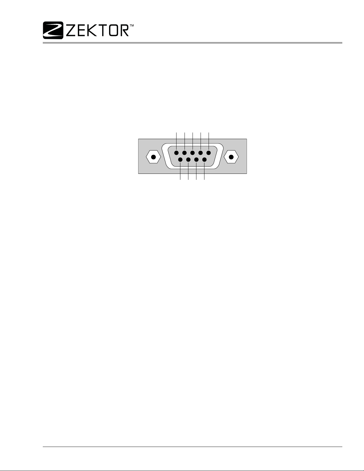
RS-232 Port Hardware
RS-232 Pinout and Baudrate Settings
The RS-232 port on the MAS7.1 is the same format, and pinout, as a PC modem, and uses the same type of
cable as a standard serial modem would, which is a st an dard straight through cable. Do not use a cable that is
marked as a “Null Modem” cable.
The MAS7.1 can also be used with any USB to RS-232 conversion cable, these are all typically straight
through cables. (Be sure to install any drivers that come with the USB to RS-232 cable you are using.)
The RS-232 port is a female type DE-9 connector (sometimes mistakenly referred to as a DB-9 connector) with
the following pinout:
Pin definitions:
1 - No Connect 6 - No Connect
2 - TX 7 - No Connect
3 - RX 8 - No Connect
4 - No Connect 9 - No Connect
5 - GND
The port settings used by the MAS7.1 are:
Baudrate: 9600
Data Bits: 8
Stop Bits: 1
Parity: NONE
MAS7.1 Supplemental Guide, Rev 1.1, 9/28/07
3
Page 4

MAS7.1 Quick Reference
Command Syntax
The MAS7.1 serial command set uses an ASCII based protocol and a terminal emulator, like Hyperterm, can
be used to test the serial port of the MAS7.1.
Each serial command is formatted as:
CMD param1,param2,...<CR>
Where:
CMD = The name of the command.
param = Any number of parameters can follow a command.
<CR> = The carriage return character, usually the character associated with the “Enter” key.
For instance the name of the command turn power on and off is ‘P’ (must be capitalized) therefore,
to turn on the MAS7.1 send a:
P 1<CR>
to turn off the MAS7.1 send a:
P 0<CR>
the commands will not be echoed back, but instead you will receive a command response string.
Command Responses
The MAS7.1 will always respond to a command, there are no “time-out” modes, if you send a command and
don’t get a response in 100ms, something’s wrong with the connection.
There are three different types of responses: Acknowledgements, Errors and Query Strings.
The Acknowledgement Response
Every command will get either an acknowledgement or error response.
Anytime you issue a command and there are no errors, you will receive the acknowledgement response.
Which is:
+<CR><LF>
which is the ‘+’ character followed by a carriage return (hex=0Dh) and a line feed (hex=0Ah).
The Error Response
Every command will get either an acknowledgement or error response.
If something is wrong with the command, you will get an error response. Which is
!<err><CR><LF>
which is the ‘!’ followed by an error number (in ASCII), followed by a carriage return and line feed.
For instance ‘2’ is not allowed as a parameter in the ‘P’ (power) command, so:
P 2<CR>
would cause the MAS7.1 to respond with:
!2<CR><LF>
the ‘2’ being the error code for “Parameter out of range”.
For the full listing of error codes, see: “
Error Response Codes” on page 9
4
MAS7.1 Suplemental Guide, Rev 1.1, 9/28/07
Page 5

MAS7.1 Quick Reference
Command Responses (Continued)
Query Strings
A query string is a command string that you would normally send to the MAS7.1, proceed ed by the ‘=’ character, and with the parameters filled in to reflect the current state of the command. Commands return a query
string when a ‘?’ is used as a parameter.
For instance to find the current power on / off state of the MAS7.1 send:
P ?<CR>
and, assuming the power is on, it will respond with:
+<CR><LF>
=P 1<CR><LF>
The ‘+’ is the acknowledgement, indicating there were no errors in the command, the next line is the power
command’s current setting, the ‘1’ indicates the power is turned on.
You can setup the MAS7.1 to send query strings when some thing changes, for inst ance when the power is toggled. See: “
Checksums and CRC8’s
You can optionally append a checksum or a CRC8 checkcode to the end of any serial command and it will be
tested by the MAS7.1. If the checksum or CRC8 checkcode does not match, the command will be rejected with
a “!4” error response.
To add a checksum to a command, append a ‘;’ followed by the calculated checksum. For instan ce to turn on
the MAS7.1 using a checksummed command:
P 1;220<CR>
To add a CRC8 checkcode to a command, append a ‘:’ followed by the CRC8 checkcode. For instance to turn
on the MAS7.1 using a CRC8 checkcoded command:
P 1:221<CR>
By setting the proper control flags, you can also have the MAS7.1 append a CRC8 checkcode or a checksum
to all of its response strings. See: “
For more information on checksums and CRC8 checkcodes, and how they’re calculated, see: “
and CRC-8 Checkcodes” on page 28.
Master / Slave and Asynchronous Modes of Operation ” on page 27
‘XS’ Control Settings (*)” on page 21.
Checksums
MAS7.1 Supplemental Guide, Rev 1.1, 9/28/07
5
Page 6

MAS7.1 Quick Reference
MAS7.1 Quick Command Reference
The quick reference tables and command descriptions refer to Inputs, Zones (or outputs) and Channels.
Inputs = The number of inputs a switch has. The MAS7.1 is a 3x1 switch and has 3 Inputs.
Zones = Number of Zones, or outputs, a switch has. The MAS7.1, a 3x1 switch, has 1 Zone.
Channels = The breakaway channels. These are signals that can be switched indepe ndently of each other.
They are referred to in the commands by a single letter.
The MAS7.1 has 4 channels:
M - Multichannel audio (the 5.1 audio connections).
A - Analog audio (the L&R stereo connections).
D - Digital audio.
H - HDMI video.
Some notes on using the tables:
• Each command is followed by a <CR> (not shown in the tables).
• The ‘Command’ column shows the syntax of the commands. The values in italics are variables and are
described in the ‘Comments’ column. The no n-ita lic characters ar e literals and should b e used as sh own.
• Many commands allow a variable number of argument s, the examples shown her e are common u sages
of the commands, for more details refer to the complete command reference.
• All command names are case sensitive. The parameters used in commands are not case sensitive.
• Most commands can be queried by replacing their parameters with a ‘?’ character.
• The MAS7.1 is a 3x1 switch and has only one output zone. The command set used by the MAS7.1 is
designed to be compatible with our line of matrix switches, to make writing a “universal Zektor device
driver” easier . Because of th is, many of the com mands requir e you to supply a n output zone, and for the
MAS7.1, the value can only be ‘1’.
The commands in this table that are marked with a ‘x’ in the ‘U’ column are universal throughout most of the
Zektor product line. By using only these commands a Zektor universal driver can be more easily written.
Table of MAS7.1 Commands
U Command Description Comments
xP p Power control p=power state (0=off, 1=on, +=toggle).
xSZ 1,n Set zone to input 1=Zone, n=Input (1-3,+,-).
xSZ 1,Mn,An,Dn,Hn Set inputs w/breakaway 1=Zone, n=Inputs (1-3,+,-). M=Multichannel, A=Stereo, D=Digital, H=HDMI
xMZ 1,m Mute zone 1 Mutes everything. 1=Zone, m=Mute (0=Normal, 1=Muted, +=Toggle).
xMZ 1,Mm,Am,Dm,Hm Mute w/breakaway Mutes only the given chans. 1=Zone, m=Mute (0,1,+), M=Multi, A=Stereo, D=Digital, H=HDMI
xDZ 1,Md,Ad,Dd,Hd Set delays Set delay times for each chan. 1=Zone, d=Delay (in ms). M=Multi, A=Stereo, D=Digital, H=HDM
x V ? Get version string Returns: Product name and firmware version string.
xLI mode,dim,bri Sets LED intensities mode=Mode (0=off, 1=dim, 2=bright, 3=auto), dim=Dim level (0-99), bri=Bright level (1-100).
x Q ? Query for statu s Returns: Operating status flags (see text).
x QZ ? Query for no. of zones & inputs Returns: Number of zones, number of inputs, and breakaway channel options.
x IR ? Read last IR code Returns: Last IR code received.
IRC cmd,ircode Set (learn) an IR code cmd=Command being set (see text), ircode=New IR code for command.
B b,b,... Emulate button presses b=Button Codes (up to 16 codes per ‘B’ command, see text).
x SS n,$ Save current settings Save current settings in EEPROM. n=Settings to save (see text).
x FS 246,$ Reset to factory settings Resets everything back to their factory default settings!
x XS flags Control settings Set / reset control options. flags=Control option flags (se e te x t).
x XE flags
FPC pri,sec,sync Front panel control pri=Primary setting (1-3,+), sec=Secondary setting (1-3,+), sync=Sync setting (0,1,+).
PSM flags Primary / secondary mapping Maps channels to the primary or secondary buttons. flags=Map flags (see text).
MCS flags Multichannel split Maps split between multichannel and analog stereo connections. flags=Split flags (see text).
Transmit enable flags Enable commands to asynchronously send there status . flags=Enable flags (see text).
6
MAS7.1 Suplemental Guide, Rev 1.1, 9/28/07
Page 7

MAS7.1 Quick Reference
MAS7.1 Quick Reference (Continued)
A Simple Control Example
If you’re not looking to write a driver that will control this and all Zektor products, then here is an example of a
couple of commands that will most likely do everything you’ll need in a simple installation.
<CR> = A Carriage Return, all commands end with a <CR>.
<CR><LF> = A Carriage Return, Line Feed, all responses end with a <CR><LF>.
Powering On / Off
To power on the MAS7.1 issue the following command:
P 1<CR>
To power off the MAS7.1 issue this command:
P 0<CR>
Controlling the Front Panel Settings
To simulate the pressing of a Primary Button:
FPC pri<CR>
Where:
pri = A number between 1 and 3 indicating which primary button you’re pressing.
If the Sync LED is lit, the both the primary and secondary LEDs will change, if it is not lit, only the primary LEDs
will change, similar to pressing the front panel buttons 1-3.
To sequence through the inputs:
FPC +<CR>
The ‘+’ can be used in many cases to sequence or toggle a value. To sequence in the opposite order, use the
‘-’ character.
To simulate the pressing of a Secondary Button (S1 - S3):
FPC ,sec<CR>
Where:
sec = A number between 1 and 3 indicating which secondary button you’re pressing.
If the Sync LED is lit, the both the primary and secondary LEDs will change, if it is not lit, only the secondary
LEDs will change, similar to pressing the front panel buttons: S1-S3.
To simulate the pressing of the Sync Button:
FPC ,,+<CR>
This command will toggle the Sync LED on and off, similar to pressing the front panel ‘Sync’ button.
MAS7.1 Supplemental Guide, Rev 1.1, 9/28/07
7
Page 8

MAS7.1 Quick Reference
A Simple Control Example (Continued)
To turn on the Sync LED:
FPC ,,1<CR>
and to turn off the Sync LED:
FPC ,,0<CR>
To set the primary selection to 2, the secondary selection to 1, and to turn off the SYNC LED:
FPC 2,1,0<CR>
Reading the Current Settings
To query the MAS7.1 for its current state, use the ‘?’ as the only parameter and the MAS7.1 will respond with a
‘=’ followed by the command with the current settings as parameters.
To read the power on state of the MAS7.1
P ?<CR>
the MAS7.1 will respond with
+<CR><LF> This indicates the command was accepted with no errors
=P 1<CR><LF> This indicated the MAS7.1 is currently ON
To read the front panel settings:
FPC ?<CR>
the MAS7.1 will respond with:
+<CR><LF> Command accepted
=FPC 2,1,0<CR><LF> Indicates the primary is 2, the secondary is 1, and the SYNC LED is OFF
8
MAS7.1 Suplemental Guide, Rev 1.1, 9/28/07
Page 9

MAS7.1 Command Reference
The MAS7.1 Command Set
Examples are given for many of the ways a command can be issued. Most commands have a ‘set’ mode for
changing a parameter value, and a ‘query’ mode for reading the current value.
If the command has a query mode, the associated response string, it will be listed.
As described in the section on the K.I.S.S.™ protocol, whitespaces and commas are optional in many cases.
The format used here includes a single space after the command and commas, with no spaces, between
parameters. The format given here does not show the optional checksum or CRC-8 checkcodes that may be
appended to all commands, nor does it show the required <CR> that terminates all commands.
The response strings are the strings returned from MAS7.1, which use the same format as described above.
The format does not show the optional checksum or CRC-8 checkco des that may be appended to all response
strings if enabled, nor does it show the <CR><LF> that terminates all Response Strings.
Error Response Codes
The following are the Error Response codes that can be returned by the MAS7.1:
!1 Unrecognized command.
!2 A parameter was out of range.
!3 Syntax error, a badly formed command.
!4 Checksum or CRC-8 error.
!5 Too many or too few parameters.
!6 Device busy, cannot process command.
!7 Buffer overflow.
And some more detailed descriptions of their meanings:
Error 1: The command given was not recognized as a MAS7.1 command. Commands are case sensitive and
in the MAS7.1, all commands are upper case.
Error 2: One of the parameters given was too large, or too small, the command will be ignored.
Error 3: Something was wrong with the command' s syntax. There was p ossibly extra data at the end o f the line,
or non-decimal data as part of a p aram eter. There cannot be whitespace before or after a checksum or CRC-8
checkcode, or this error will be returned.
Error 4: The ';' or ':' character was used to indicate a Checksum or CRC-8 Checkcode was appended to the
command string, but the Checksum or CRC-8 Checkcode did not match the calculated one. The command will
be ignored.
Error 5: The number of parameters given does not match the number allowe d by this command.
Error 6: To prevent conflicts between the front panel Setup Mode and the serial port settin gs, when the MAS7.1
is in the Setup Mode, many parameters become read only and any attempt at writing them will return Error 6.
Issuing the “Button Emulation” command with button code ‘0’ can be used to exit the Setup Mode, at which
point the command can be re-issued without an Error 6 response.
Error 7: An internal buffer has overflowed, for instance more than 16 button codes were sent as part of the
“Button Emulation” command.
MAS7.1 Supplemental Guide, Rev 1.1, 9/28/07
9
Page 10

MAS7.1 Command Reference
Command Definitions
The commands are defined in alphabetical order.
(*) In an effort to make “Zektor Universal Drivers” easier to write, Zektor has adopted a subset of “Universal
Commands”. By using only these commands, it should be possible to write a driver that works with all Zektor
products. Reducing the ef fort of writing driver s for mult iple Zektor prod uct s. The comma nds that ar e p art of the
Universal Command Set will be marked with a (*).
‘B’ Button Emulation
This command allows access to the internal keyboard handling of the MAS7.1, and is very hardware dependent. Button values returned by the MAS7.1 may and most likely will be different than button values returned
by other Zektor devices.
Each button generates a value upon being pressed, and a different value upon release.
The Power toggle button also generates a unique value when held for 4 seconds, which is used to enter the
setup mode. Other combinations may also generate unique codes.
This command allows the controller to detect front panel button pr esses even when the front p anel is disabled .
This allows the controller very tight control over the MAS7.1. By disabling the front panel (see: “
Settings (*)” on page 21), and by then processing the front panel button presses of the MAS7.1, the user can
redefine the operations of the MAS7.1.
When used in combination with the “Read Last IR Code” command, eve n IR commands can be hand led by the
user, outside the MAS7.1’s firmware.
Because of the tight link between this command and the MAS7.1’s firmware, there are some caveats when
using this command. The Zektor firmware expects a button press code to always be followed by a button
release code. Sending these codes out of logical order will not harm the MAS7.1, but may result in unpredictable behavior (buttons codes ignored, or unexpected state changes).
B b1,bn... Send one or more button codes to the MAS7.1.
B ? Query for any buffered button presses.
B Query for any buffered button presses.
‘XS’ Control
Response String:
=B b1,bn...
Where:
b1,bn.. = A variable number of button codes (1 to 16 codes per command).
In the Master / Slave mode, only the last 16 button presses will be logged between queries, after that, new button presses overwrite the old ones in the internal buffer and will be lost to the controller.
The maximum number of button codes that can be sent is 16. If more than 16 button codes are sent a “parameter count error” will be returned and only the first 16 button codes will be accepted.
10
MAS7.1 Suplemental Guide, Rev 1.1, 9/28/07
Page 11

‘B’ Button Emulation (Continued)
The Button Codes for the MAS7.1 are defined as follows:
MAS7.1 Command Reference
Button
Power Toggle 1 9
1210
2311
3412
S1 5 13
S2 6 14
S3 7 15
SYNC 8 16
The “Press Code” is the value returned when a button pressed, and the “Release Code” is the value returned
when a button is released.
There are also a small number of codes that are unique to this command that cannot be ge ne rated by the ke yboard. These extended codes allow for better control of the MAS7.1.
Some extended button codes are:
Code
0 When Issued: Exits any setup modes.
0 When returned by query: No buttons have been pressed since last the query.
100 Always toggle power (like ‘Power Toggle’ without the need of a release code).
101 Discrete power on (always turns on power).
102 Discrete power off (always turns off power).
103 Sequence through inputs.
104 Sequence through secondary inputs.
105 Turn SYNC on.
106 Turn SYNC off.
Press Code Release Code
Description
The ‘0’ code has special meaning. When returned in a Query Response string it means there are no keys waiting in the buffer. When issue by the user, it acts like an exit key, used to exit setup modes, similar to pressing
the Power Toggle button, but it will be ignored if the MAS7.1 is not in a setup mode. By issuing ‘0’ codes, the
MAS7.1 can be returned to a known state, regardless of any possible setup state it might be in.
The ‘0’ button code is also device independent. Its use, and value, does not change between Zektor devices
like the other codes may (and most likely will).
‘DZ’ Delay Settings (*)
Allows setting of the switching delays. Switching delays refer to the amount of time the channel is muted when
switching from one input to another. This is sometimes called “Fade to Black” even though there is no “Fading”
involved. When switching from one channel to another, the MAS7.1 will mute the channel for a programmable
amount of time. For instance if the digital audio section is set to 200ms, then anytime the digital audio section
is switched, the digital audio will be muted for 200ms before being switched to the new channel. Each of the
channels operate independently and different times can be set for each of the chan nels.
Some receivers can “thump” if their digital audio is switched too fast, switching delays can help prevent this.
Some HDMI monitors require much longer than the 100ms required by the HDMI standard, setting the HDMI
switching delay can help with these monitors.
If the MAS7.1 is being used to switch component video, a delay that’s long enough to allow the monitor to
detect a signal loss, can prevent the “rolling” that sometimes occurs when switching component video.
MAS7.1 Supplemental Guide, Rev 1.1, 9/28/07
11
Page 12

MAS7.1 Command Reference
‘DZ’ Delay Settings (Continued)
Matrix switches (switches with more than one zone) can have each zone set independently. The MAS7.1 has
only one zone. For compatibility with multi-zoned switches, the zone must be specified and must be ‘1’.
DZ 1,Mnn,Ann,Dnn,Hnn,$ Set new settings
DZ ? Query for current settings
Response String:
=DZ 1,Mnn,Ann,Dnn,Hnn
Where:
1 = Zone (Must be ‘1’).
Mnn = Multichannel switching delay in millisecond increments (nn=Number of milliseconds).
Ann = Analog audio switching delay in millisecond increments (nn=Number of milliseconds).
Dnn = Digital audio switching delay in millisecond increments (nn=Number of milliseconds).
Hnn = HDMI switching delay in millisecond increments (nn=Number of milliseconds).
$ = Optional, but if present settings are backed up in EEPROM.
The ‘M’, ‘A’, ‘D’ and ‘H’ characters are literals and are used to indicate which delay is being set. If no prefix is
used, all channels will be set to the given delay.
The ‘nn’ is a variable and indicates the delay time in milliseconds.
Not all parameters have to be present, and they do not have to appear in any particular order. For instance to
set only the digital audio delay to 200ms:
DZ 1,D200
To set the analog audio (the L&R inputs) to use a 100ms delay, and the multitchannel audio (the 5.1 audio) to
use a 200ms delay:
DZ 1,A100,M200
‘FPC’ Front Panel Control
This command is specific to the MAS7.1 and is used to control the front panel directly.
FPC pri,sec,sync
Response String:
=FPC pri,sec,sync
Where:
pri = Setting of the primary LEDs that are labeled 1-3. Value = 1-3.
sec = Setting of the secondary LEDs that are labeled S1-S3. Value = 1-3.
sync = Setting of the SYNC LED. Value = 0 or 1.
To sequence through inputs, or toggle the SYNC LED you can use the ‘+’ and ‘-’ characters in place of the ‘pri’,
‘sec’ and ‘sync’ settings.
To simulate the pressing of the 3 button:
FPC 3
If the Sync LED is lit, the both the primary and secondary LEDs will change, if it is not lit, only the primary LEDs
will change, similar to pressing the front panel buttons 1-3.
12
MAS7.1 Suplemental Guide, Rev 1.1, 9/28/07
Page 13

MAS7.1 Command Reference
‘FPC’ Front Panel Control (Continued)
To sequence through the primary inputs:
FPC +
To simulate the pressing of the S2 Button:
FPC ,2
If the Sync LED is lit, the both the primary and secondary LEDs will change, if it is not lit, only the secondary
LEDs will change, similar to pressing the front panel buttons: S1-S3.
To simulate the pressing of the Sync Button, use the toggle option:
FPC ,,+
This command will toggle the Sync LED on and off, similar to pressing the front panel ‘Sync’ button.
‘FS’ Restore Factory Default Settings (*)
To restore the MAS7.1 to its factory default settings:
FS 246$
This will set everything back to the programmed factor y set tin gs . Th is includes timings, IR codes (all learned
IR codes will be lost), front panel LED intensity settings, etc. Everything, means everything!
‘IR’ Query Last IR Code Received (*)
This command allows the user to read the values returned by Zektor’s IIR™ (Intelligent Infra-Red) decoding
firmware. Zektor’s IIR™ algorithm converts all IR codes it receives to a compressed, 72 bit value.
Each different key press of a remote control will generate a different but repeatable pattern.
This command returns a value for every IR code detected by the front panel IR sensor (or IR jack if enabled),
regardless as to whether the IR code detected was used to control the MAS7.1.
The uses for this command are two fold:
1. The value returned from this command are the same values used to teach the MAS7.1 new IR codes
over the serial port. (See the “Set Learnable IR Command Codes” command).
2. This command gives the controller full access to the MAS7.1’s IR sensor and Zektor’s IIR™ algorithm.
This is a very reliable way of adding IR control to any project. The IR codes generated by Zektor’s IIR™
algorithm are immune to timing differences between universal rem ote control manufacturers and to the
timing errors associated with conditio n of the re m ot e con tr ol’s battery.
Note 1: The Zektor’s IIR™ algorithm works with any remote control code that is time modulated. This is pretty
much every type of IR code except the Phillips RC-5, and RC-6 codes.
Note 2: Because very few controllers could handle a 72 bit decimal value, and in an effort to keep the size of
the IR response small, this command sends the 72 bit IR code as an 18 digit hexadecimal value.
The format of the command is:
IR ? Query for the IR code of the last IR command received.
Response String:
=IR ircode
Where:
ircode = 18 hex digits (0-9, A-F), representing the most recent IR code received.
This command returns a single digit ‘0’ if there are no IR codes waiting to be read.
MAS7.1 Supplemental Guide, Rev 1.1, 9/28/07
13
Page 14

MAS7.1 Command Reference
‘IRC’ Set Learnable IR Code
This command is used to set, or retrieve, the current IR codes associated with the learnable IR commands.
This could be useful for “cloning” the IR codes learned in one MAS7.1 into another MAS7.1.
IRC ircmd,ircode Set the ‘ircmd’ to use the IR code ‘ircode’.
IRC ircmd,? Query for a single IR command.
IRC ? Query for all ‘ircmd’ settings.
Response String:
=IRC ircmd,ircode
Where:
ircmd = IR command number being set / retrieved (See Table).
ircode = 72 bit (18 hex digits) IR code (See: “IR” command).
The value ‘ircmd’ refers to the IR commands that the MAS7.1 is able to learn, they are:
IRCmd
1 Toggle Power
2 Select Input 1
3 Select Input 2
4 Select Input 3
5 Select Input S1
6 Select Input S2
7 Select Input S3
8 Toggle SYNC
9 Discrete Power On
10 Discrete Power Off
11 Sequence through inputs
12 Sequence through secondary inputs
13 T urn on SYNC LED
14 Turn off SYNC LED
Setting an ‘ircmd’ to ‘ircode = 0’, causes that command to no longer respond to IR.
IR codes are always saved in EEPROM.
‘LI’ Front Panel Light Intensities and Mode (*)
Set the mode, dim and bright levels of the front panel LEDs:
LI mode,dim,bright Set the MODE, DIM, and BRIGHT.
LI mode,dim,bright,$ Set levels, and backup settings in EEPROM.
LI ? Query for current settings.
Description
Response String:
=LI mode,dim,bright
Where:
mode = MODE setting.
dim = DIM level setting.
bright = BRIGHT level settings.
14
MAS7.1 Suplemental Guide, Rev 1.1, 9/28/07
Page 15

MAS7.1 Command Reference
‘LI’ Front Panel Light Intensities and Mode (Continued)
Where ‘mode’ settings are:
0 = Turn off front panel lights.
1 = Front panel lights are always at dim level.
2 = Front panel lights are always at bright level.
3 = Front panel lights auto-dim after 4 seconds.
The dim and bright intensities range from 0=Off, to 100=Maximum brightness.
If the levels are set, but the ‘$’ suffix is not used, the levels the new levels will not be restored after a power fail-
ure. The ‘$’ suffix is used to backup the new settings in EEPROM, which will be restored after a power failure.
‘MCS’ Multi-Channel Split
The split between the multichannel connections and the analog audio connection is usually between the 5.1
connectors and the L & R stereo connectors, but this can be changed.
MCS flags Set the multichannel / analog audio split.
MCS flags,$ Set the multichannel / analog audio split, backup settings in EEPROM.
MCS ? Quer y for the current settings.
Response String:
=MCS flags
Where ‘flags’ is a bitmapped parameter defined as:
Decimal Value +128 +64 +32 +16 +8 +4 +2 +1
Bit Position 7
Connector Name R L RR LR CEN SUB RF LF
Factory Setting00111111
LF - Left Front connector
RF - Right Front connector
SUB- Subwoofer connector
CEN - Center channel connector
LR - Left Rear connector
RR - Right Rear connector
L - Left stereo audio connector
R - Right stereo audio connector
This command uses a bitmapped parame ter. See: “Using Bitmapped Parameters” on page 24.
Each bit represents the mapping for one connector, as defined in the above table.
If a bit is set to a one, the corresponding connector is mapped to the multichannel audio channel and an fol-
lows the breakaway option of the ‘M’ channel.
If the bit is set to a zero, the connector becomes part of the analog audio channel and follows the breakaway
options of the ‘A’ channel.
The ‘Decimal Value’ in the table’s header, refer s to the value s adde d togeth er to create the decimal parameter
used by the command. For instances if you only wanted th e ‘CEN’ and ‘SUB’ to be considered p ar t of the “multichannel audio”, then only those bits would be set to one, and the rest of the bits set to zero. The parameter
value would be calculated as: 8+4, making the parameter va lue: 12.
The command to directly map the ‘CEN’ and the ‘SUB’ connectors to multichannel audio, and set the rest of
the connectors to the analog audio channel would be:
MCS 12
If the settings are changed, but the ‘$’ suffix is not used, the new settings will not be restored after a power failure. The ‘$’ suffix is used to backup the new settings in EEPROM, which will be restored after a power failure.
MAS7.1 Supplemental Guide, Rev 1.1, 9/28/07
15
Page 16

MAS7.1 Command Reference
‘MZ’ Mute (*)
This command is used to mute the outputs of the MAS7.1, either all at once, or just selected channels.
To mute or unmuted outputs:
MZ 1,m Mute or unmute everything
MZ 1,Mm,Am,Dm,Hm Mute or unmute selected channels
Response String:
=MZ 1,Mm,Am,Dm,Hm
Where:
1 = Zone, must be 1.
m = Mute value, 0=Normal (unmute), 1=Mute.
Mm= Mute or unmute the multchannel audio channel.
Am = Mute or unmute the analog audio channel.
Dm = Mute or unmute the digital audio channel.
Hm = Mute or unmute the HDMI video channel.
The ‘M’, ‘A’, ‘D’ and ‘H’ characters are literals and are used to indicate which channel is being muted. If no prefix is used, all channels will be affected.
The ‘m’ is a variable and indicates the mute setting (0=Not muted, 1=Muted).
Not all parameters have to be present, and they do not have to appear in any particular order. For instance to
mute only the digital audio:
MZ 1,D1
To mute the analog audio (the L&R inputs) and unmute the multitchannel audio (the 5.1 audio):
MZ 1,A1,M0
P’ Power Control (*)
Turn on / off, or toggle the power state of the MAS7.1:
P 0 Turn off power
P 1 Turn on power
P + Toggle power
P ? Query for current setting
Response String:
=P n
Where:
n = Current power status, 0=Off, 1=On.
‘PSM’ Primary / Secondary Mapping
This command allows you to map which channels switch with the primary buttons (1-3) and which channels
switch with the secondary buttons (S1-S3).
PSM flags
PSM flags,$
Response String
=PSM flags
16
MAS7.1 Suplemental Guide, Rev 1.1, 9/28/07
Page 17

MAS7.1 Command Reference
‘PSM’ Primary / Secondary Mapping (Continued)
Where ‘flags’ is a bitmapped parameter defined as:
Decimal Value +128 +64 +32 +16 +8 +4 +2 +1
Bit Position 7
Connector Name HD MA AA DA
Factory Setting00000100
DA - Digital audio
AA - Analog audio (Stereo)
MA - Multichannel audio (5.1)
HD - HDMI video
This command uses a bitmapped parame ter. See: “Using Bitmapped Parameters” on page 24.
Each bit represents the mapping for one channel, as defined in the above table.
If a bit is set to a one, the corresponding channel is mapped to the primary selection buttons.
If a bit is set to a one, the corresponding channel is mapped to the primary selection buttons.
The ‘Decimal Value’ in the table’s header, refer s to the value s adde d togeth er to create the decimal parameter
used by the command. For instances if you only wanted the ‘MA’ and ‘AA’ to be considered part of the primary
selection, then only those bits would be set to one, and the rest of the bits set to ze ro. The parameter value
would be calculated as: 4+2, making the parameter value: 6.
The command to map only the ‘MA’ and the ‘AA’ channels to the primary buttons, and to backup the new settings in EEPROM, would be:
PSM 6,$
If the settings are changed, but the ‘$’ suffix is not used, the new settings will not be restored after a power failure. The ‘$’ suffix is used to backup the new settings in EEPROM, which will be restored after a power failure.
‘‘Q’ Query Status (*)
In the Master / Slave mode of operation, (see: “
The Master / Slave Mode of Operation” on page 27), this com-
mand is used to poll for any pending state changes that are waiting to be read. By issuing this command and
testing the returned bitmapped value, the controller can determine what has changed in the MAS7.1 since the
last time it was polled.
This command allows the controller to quickly poll the MAS7.1, using only one command, instead of issuing a
string of commands to check if the power state has changed, or if a new input has been selected, a button
pressed, etc. The Query Status command is used to determine if anything has changed, and then based on the
results of the Query Status, only the query commands needed are issued to read the new states of the
MAS7.1.
Once the new state is read by issuing the proper query command, the associated flag will be reset.
Q ? Query for current flag values
Response String:
=Q flags
MAS7.1 Supplemental Guide, Rev 1.1, 9/28/07
17
Page 18

MAS7.1 Command Reference
‘Q’ Query Status (Continued)
Where ‘flags’ is a bitmapped parameter:
Decimal Value +512 +256 +128 +64 +32 +16 +8 +4 +2 +1
Bit Position 9 8 7 6 5 4 3 2 1 0
Name PSM FPC MUT DLY CTL LMI IRR BTN SEL PWR
PWR- 1=Power State has changed.
SEL - 1=Selection (Input / Output Mapping) has changed.
BTN - 1=One or more buttons have been pressed.
IRR - 1=A new IR code has been received.
LMI - 1=Lighting Mode or Intensity Level Settings have changed.
CTL - 1=Control Settings have changed.
DLY - 1=Switching delays have changed.
MUT- 1=Mute settings have changed.
FPC - 1=Front panel settings have changed.
PSM- 1=Primary / secondary mappings have changed.
This command uses a bitmapped parameter. See: “Using Bitmapped Parameters” on page 24.
‘QZ’ Query for Zone Information
Returns the number of Inputs, Zones, and Breakaway channels.
QZ ? Query for number of Inputs, Zones, and Breakaway channels
Response String:
=QZ inputs,zones,breakaway_opt_1,breakaway_opt_n,...
Where:
inputs = Number of inputs.
zones = Number of zones.
breakaway_opt_x = A variable number of breakaway options.
This command is used to determine the number of inp uts, zones, and the dif ferent breakaway options available
to a device.
Its response string is static (it always returns the same string).
For a MAS7.1, the response string will always read:
=QZ 3,1,H,M,D,A
Which indicates 3 Inputs, 1 Zone, and the Breakaway options H,M,D,A.
‘SS’ Save States (*)
Backs up the current states of the MAS7.1 in EEPROM.
EEPROM is a type of memory that retains its data even when power is disconnected from the MAS7.1.
There are two types of data that this command can save in EEPROM.
The first is that data that is associated with all commands that can have a ‘$’ suffix added to them.
The second option is the power on state. By default, when power is first applied to the MAS7.1, it power on in
the standby mode. If the power button it pressed, it powers itself on, with all channels pointing to input 1. This
default behavior can be changed using this command.
18
MAS7.1 Suplemental Guide, Rev 1.1, 9/28/07
Page 19

MAS7.1 Command Reference
‘SS’ Save States (Continued)
Command format:
SS states,$ Backup the selected states into EEPROM
Where:
states = States to backup.
1 = Backup the current configuration as the new power on settings.
2 = Backup all unsaved data from commands that can be suffixed with a ‘$’.
3 = Backup all unsaved data and save new power on settings.
This command can be use to delay the saving of data in commands that can have their data saved in
EEPROM.
For instance the LED mode settings can be changed using:
LI 3
This command will set the MAS7.1 to have its LED on bright all the time, but because the command was not
suffixed with the ‘$’ character, the setting is only valid until power is disconnected from the MAS7.1. Once
power is restored the settings used will be those that were previously saved in EEPROM.
To save the new LI settings you can issue the LI command with just a ‘$’
LI $
Or you can use the ‘SS’ command to save all unsaved data, which will include the LI setting:
SS 2,$
The ‘SS’ command is also used to change the initial power on settings.
For instance if when initially plugged in, you want the MAS7.1 to turn itself on and switch to input 2, you can:
P 1 Turn on the MAS7.1
SZ 1,2 Switch to input 2
SS 1,$ Save the current configuration as the new power on settings
‘SZ’ Set Input (*)
This is the command used to change inputs on the MAS7.1 in a Zektor universal way, meaning that this command will work on Zektor matrix switches as well as the MAS7.1. Using this command the MAS7.1 is treated
as a 3 input, 1 zone matrix switch.
SZ 1,in Switch all channels to new input
SZ 1,Min,Ain,Din,Hin Switch the breakaway channels’ inputs
SZ ? Read the current settings
Response String:
=SZ 1,in or,
=SZ 1,Min,Ain,Din,Hin
Where:
1 = Zone, must be 1.
in = Input 1-3.
M = Mutlichannel audio channel.
A = Analog audio (L & R stereo) channel.
D = Digital audio channel.
H = HDMI video channel.
MAS7.1 Supplemental Guide, Rev 1.1, 9/28/07
19
Page 20

MAS7.1 Command Reference
‘SZ’ Set Input (Continued)
The command has two modes of operation, a no n- b re ak awa y an d a br ea ka wa y mo de .
If no breakaway channels are specified then it’s assumed all channels are to be switched, for instance :
SZ 1,3
will set everything to input 3
Whereas:
SZ 1,A3,D1,H2
will switch the analog audio ‘A’ to input 3, the digital audio ‘D’ to input 1 and the HDMI video ‘H’ to input 2.
When a response string is requested:
SZ ?
The response will depend upon the breakaway settings, if all of them are the same (like the first example) then
only the input will be returned. For instance the first example would return:
=SZ 1,3
If breakaway is in effect (different channels point to different inputs), then they will be listed separately. For
instance, assuming the Multichannel audio is currently switched to ‘2’, the second example would return:
=SZ 1,M2,A3,D1,H2
‘V’ Version Query (*)
Query for the current firmware version of the MAS7.1.
V ? Request version string
V Request version string
Response String:
=V MAS7.1 firmware_ver firmware_serial_number
Where:
firmware_ver = Version number of the MAS7.1’s firmware.
firmware_serial_number= Internal serial number (does not match the product’s serial number).
‘XE’ Transmit Enable Settings (*)
In the Asynchronous mode of operation, the MAS7.1 will transmit state changes as they occur. This command
allows individual control over which state changes will be transmitted.
This MAS7.1 allows control over the following states:
• Power State changes (On / Off condition).
• Selection changes (input / output mapping changes).
• Front Panel modes and intensity changes
• Front Panel Button Presses.
• IR codes received.
• New IR codes learned.
• Control Settings changes.
Each of the above states can be selectively set to asynchronously transmit their state changes, or run in the
Master / Slave mode. If asynchronous transmit has been disabled for one of the options, then that option will
revert to the Master / Slave mode.
20
MAS7.1 Suplemental Guide, Rev 1.1, 9/28/07
Page 21

‘XE’ Transmit Enable Settings (Continued)
MAS7.1 Command Reference
The ‘AS’ in the “Control Settings” command, (see: “
‘XS’ Control Settings (*)” on page 21), must be set to ‘1’ to
allow any Asynchronous transmissions, if the ‘AS’ bit is set to zero, then the MAS7.1 will operate solely in the
Master / Slave mode regardless of the settings of this command.
XE settings Set the enable bits to ‘settings’
XE +settings Set enable bits indicated in ‘settings’ to 1
XE -settings Reset enable bits indicated in ‘settings’ to 0
XE settings,$ Set the control bits to ‘settings’, save in EEPROM
XE ? Query for current settings
Response String:
=XE settings
Where ‘settings’ is a bitmapped parameter:
Decimal Value +512 +256 +128 +64 +32 +16 +8 +4 +2 +1
Bit Position 9 8 7 6 5 4 3 2 1 0
Name PSM FPC MUT DLY CTL LMI IRR BTN SEL PWR
Factory Settings0000000011
PWR- 1=Power State has changed.
SEL - 1=Selection (Input / Output Mapping) has changed.
BTN - 1=One or more buttons have been pressed.
IRR - 1=A new IR code has been received.
LMI - 1=Lighting Mode or Intensity Level Settings have changed.
CTL - 1=Control Settings have changed.
DLY - 1=Switching delays have changed.
MUT- 1=Mute settings have changed.
FPC - 1=Front panel settings have changed.
PSM - 1=Primary / secondary mappings have changed.
This command uses a bitmapped parameter, see: “Using Bitmapped Parameters” on page 24.
The ‘$’ parameter is a “Backup Control Settings” flag. If it exists, then the current settings will be backed up in
EEPROM, and will remain unchanged through a power failure. Backing up the “Transmit Enable Settings” will
also backup the “Control Settings”, see: “
‘XS’ Control Settings (*)” on page 21.
‘XS’ Control Settings (*)
Turn on and off operational modes of the MAS7.1.
This command allows control over the following:
• Select the Master / Slave or Asynchronous modes of operations.
• Enable / Disable the front panel switches.
• Enable / Disable the IR control.
• Enable / Disable the IR jack.
• Enable / Disable appending Checksums or CRC-8’s to responses.
The format of the command is:
XS settings Set the control bits to ‘settings’
XS +settings Set bits indicated in ‘settings’ to 1
XS -settings Reset bits indicated in ‘settings’ to 0
XS settings,$ Set the control bits to ‘settings’, and save in EEPROM
XS ? Query for current settings
MAS7.1 Supplemental Guide, Rev 1.1, 9/28/07
21
Page 22

MAS7.1 Command Reference
‘XS’ Control Settings (Continued)
Response String:
=XS settings
Where ‘settings’ is a bitmapped parameter:
Decimal Value +128 +64 +32 +16 +8 +4 +2 +1
Bit Position 7 6 5 4 3 2 1 0
Name 12V CRC CSE IRJ IRS IRE FP AS
Factory Settings00011110
AS - 0=Master / Slave mode. 1=Asynchronous Mode.
FP - 0=Disable Front Panel. 1=Front Panel Enabled
IRE - 0=Disable IR Control. 1=Enable IR Control.
IRS - 0=Turn off IR Sensor. 1=Turn on IR Sensor.
IRJ - 0=Turn off IR Jack. 1=Turn on IR Jack.
CSE- 0=Disable CS and CRC-8 1=Append either Checksums or CRC-8 to responses.
CRC- 0=Append Checksums, 1=Append CRC-8’s, to responses.
12V - 0=12V disabled 1=Use IR Jack as 12V On / Off Control
This command uses a bitmapped parameter. See: “Using Bitmapped Parameters” on page 24.
If the ‘$’ parameter exists, then the current settings will be backed up in EEPROM, and will remain unchanged
through a power failure. Backing up the “Control Settings” will also backup the “Transmit Enable Settings”, see:
“
‘XE’ Transmit Enable Settings (*)” on page 20.
The IR control (IRE) and the IR jack (IRS), work differently when disa bled. Disabling IR control, by setting the
‘IRE’ bit to zero, keeps the MAS7.1 from responding to any IR codes, however the front panel sensor remains
operational and any codes received can still be queried for by using the “IR ?” command. Disabling the IR sensor (IRS) and enabling IR control (IRE), allows the MAS7.1 to respond to IR signals through the IR jack, any
signal received by the IR sensor will be ignored.
Disabling the IR jack, by setting the ‘IRJ’ bit to zero, completely disables the IR jack. IR commands are no longer be received through the IR jack if the ‘IRJ’ bit has been set to zero.
The ‘IRJ’ flag and ‘12V’ are mutually exclusive. Any attempt to set them both will result in the ‘12V’ option being
disabled.
22
MAS7.1 Suplemental Guide, Rev 1.1, 9/28/07
Page 23

K.I.S.S.™ Keep It Simple Serial
The K.I.S.S.™ Command Structure Overview
The section of the manual describes the overall structure of the K.I.S.S.™ protocol. It only needs to be read if
you are having some problems with the way a product is behaving, or you just like reading this sort of thing.
The following conventions are used to describe the protocol:
<CR> = An ASCII Carriage Return (‘0D’ hex)
<LF> = Line Feed (‘0A’ hex)
<ESC> = An Escape character (‘1B’ hex)
Device = The Zektor device being controlled.
Controller = A PC or other system, used to control the Zektor device.
Parameter = A decimal value (0-9) that may, in some cases, be prefixed with ‘+’ or ‘-’.
A K.I.S.S.™ command in its simplest form is a command following by a <CR> for instance:
V<CR>
This will return the version number of a Zektor device.
A command can have a variable number of p arameters with option al whitespace(s) following the command, for
instance:
P1<CR>
or
P 1<CR>
will turn power on. The spaces between the ‘P’ and ‘1’ are optional. Since commands consist of alpha characters only, there can never be a ‘P1’ command and ‘P1’ will always be interpreted as ‘P 1’.
When a command has more than one parameter, the parameters are separated by either whitespace(s) or a
comma, or both whitespace(s) and a comma, for inst ance:
LI 3 3 80<CR>
or
LI 3,3 , 80<CR>
will set the front panel LEDs to auto-dim, with a low intesity setting of 3, and a high intensity setting of 80. Once
again the space between the command and 1st parame ter is optional. Space(s) may also appear before and
after the comma.
The comma is optional between parameters except when it is necessary to indicate a default parameter, for
instance:
LI ,,13<CR>
would set just high intensity level of the front panel LEDs without affecting the lower level, or the mo de. The
commas are used to indicate the 1st and 2nd parameters are not supplied and the default values should be
used (in this case the default values are the current value s, leaving th e values un changed ). The sp ace befor e
the 1st comma is optional.
Most commands can be queried for their current settings by substituting the ‘?’ for the parameter list, or by not
supplying any parameters at all. For instance to request the current LED Intensity settings:
LI ?<CR>
or
LI<CR>
This would cause the device to issue a LED Intensity Response, (the Response S tring format is described in
the paragraphs entitled: “The Response String”). The whitespace before the ‘?’ is optional.
MAS7.1 Supplemental Guide, Rev 1.1, 9/28/07
23
Page 24

K.I.S.S.™ Keep It Simple Serial
Using Bitmapped Parameters
Some commands accept “Bitmapped” parameters. These are decimal values that represent a series of flag s,
or bits, that control, enable and/or disable different device operations.
Binary arithmetic is used to represent bitmapped parameters, it is assumed the re ader has some familiarity
with binary arithmetic.
An example of a command that uses a bitmapped parameter is the “XS settings<CR>” command, which is
defined as:
XS settings<CR>
Where ‘settings’ is a bitmapped parameter:
Decimal Value +128 +64 +32 +16 +8 +4 +2 +1
Bit Position 7 6 5 4 3 2 1 0
Name 12V CRC CSE IRJ IRS IRE FP AS
Factory Settings00011110
AS - 0=Master / Slave mode. 1=Asynchronous Mode.
FP - 0=Disable Front Panel. 1=Front Panel Enabled
IRE - 0=Disable IR Control. 1=Enable IR Control.
IRS - 0=Turn off IR Sensor. 1=Turn on IR Sensor.
IRJ - 0=Turn off IR Jack. 1=Turn on IR Jack.
CSE- 0=Disable CS and CRC-8 1=Append either Checksums or CRC-8 to responses.
CRC- 0=Append Checksums, 1=Append CRC-8’s, to responses.
12V - 0=+12V disabled 1=Use IR Jack as +12V On / Off Control
The ‘Decimal Value’ in the table’s header, refer s to the values added toge ther to create the decimal parameter
used by the command. For instances if the bits ‘AS’ and ‘IRS’ where to be set to 1, and the re st of the bits set
to zero, the parameter value would be calculated as: 8+1, making the parameter value: 9.
The command to directly set those two bits, and reset all the others would be:
XS 9<CR>
Individual bits of a bitmapped parameter can be set or reset without affecting the other bits, by prefixing the bitmapped parameter with a ‘+’ to set individual bits , or a ‘-’ to reset individual bits.
For instance in the above example the bitmapped value has been set to ‘9’. If we would now like to enable the
IR remote, by setting the ‘IRE’ bit, the following command can be issued:
XS +4<CR>
The will set the ‘IR’ bit, and have no affect on the others, and the new “XS” value would be: 13
If we’d like to now disable the IR jack and the IR remote functions and the Front Panel, by clearing the ‘IRJ’,
‘IRE’ & ‘FP’ bits, we’d use the value “16+4+2”, or 22, and issue the command:
XS -22<CR>
leaving the new “XS” value to be: 1.
Using Command Checksums and CRC-8 Checkcodes
A checksum or CRC-8 checkcode may be appended to any command, and if given, will be calculated by the
device and compared with the given value. If a mismatch occurs an error will be returned and the command will
not be executed. This can be used to help assure reliable operation in noisy environments. Checksums are
more commonly used in serial protocols, however CRC-8 checkcodes offer a more secure means of insuring
error free communications.
A checksum or CRC-8 checkcode is appended to the command by adding a semicolon (‘;’) for a checksum, or
a colon (‘:’) for a CRC-8 checkcode.
24
MAS7.1 Suplemental Guide, Rev 1.1, 9/28/07
Page 25

K.I.S.S.™ Keep It Simple Serial
Using Command Checksums and CRC-8 Checkcodes (Continued)
An example of appending a checksum to a command:
LI 2,13;178<CR>
the ‘;’ indicates a checksum follows, the ‘178’ is the checksum of the command string up to and including the ‘;’
character.
In a similar fashion a CRC-8 checkcode can be appended to a command:
LI 2,13:213<CR>
The ‘:’ indicates that a CRC-8 checkcode follows, the ‘213’ is the calculated CRC-8 checkcode up to and
including the ‘:’ character.
Optional spaces are allowed before the ‘;’ and ‘:’ characters but NOT after them. The checksum must immediately follow the ‘;’ character, and a CRC-8 checkcode must immediately follow the ‘:’ character, anything else,
including whitespace, will cause a syntax error to be returned. Similarly the <CR> must immediately follow the
checksum or checkcode parameter or a syntax error will be returned.
Checksums and CRC-8 Checkcodes” on page 28 for more information on calculating checksums and
See: “
CRC-8 checkcodes, it includes source code examples of calculating both Checksums and CRC-8’ s as used by
K.I.S.S.™.
Clearing the Command Buffer
All commands are buffered and nothing is executed until the <CR> character is received. To assure that there
are no extraneous characters in the command buffer, before a command string is sent, the <ESC> character
can be issued to clear the buffer and reset any checksum or CRC-8 checkcode calculations.
This is useful when communications with the Zektor device is b e ing initialized an d the state of the device is
unknown. An <ESC> will clear the command buffer and reset all checksums and CRC-8 checkcodes.
For example:
dsLG%df<ESC>V;145<CR>
will return the Version Query Res ponse string. The “dsLG%df” represents noise that could have been in the
buffer before the command string was issued. The <ESC> clears the buffer allowing the “V;145<CR>” to be
processed error free.
It is legitimate (though seldom nessassary) to prefix all commands with the <ESC> characte r to assure the bu ffer is always empty before the command string is received, which may be helpful in some very noisy environments.
The Response Strings
A response will always be returned whenever a <CR> is received. There are no conditions where a “timeout” is
a valid response to any query.
There are only three valid responses in the K.I.S.S.™ protocol, anything else should be considered a communication error, including a timeout while waiting for a response.
Each response is prefixed by a unique character . Determining which of the three responses is received can be
done simply, by examining only the first character of any response string.
The three possible prefix characters and their associated responses are
+ The Acknowledgement Response
! The Error Response
= The Query Response
The response to a command string will always be an Acknowledgement or an Error Response.
MAS7.1 Supplemental Guide, Rev 1.1, 9/28/07
25
Page 26

K.I.S.S.™ Keep It Simple Serial
The Response Strings (Continued)
The Acknowledgement is always the string:
+<CR><LF>
and the Error Response is always the string:
!ERR<CR><LF>
By parsing only the prefix characters ‘+’ and ‘!’, a programmer can chose to ignore the error codes and simply
look at the first characters of the response strings and use them as a pass / fail indicator when issuing a command.
All response strings always end with a <CR><LF>.
A Query Response string always starts with the ‘=’ characters and is followed by a command string indicating
the parameter(s) being returned. This is better explained in an example.
An example of querying a device for its light intensity settings:
LI?<CR> Sent: Light Intensity Query command
+<CR><LF> Received: Acknowledgement of command
=LI 3,2,80<CR><LF> Received: The ‘LI’ Query Response
Note that a “+<CR><LF>” followed the command string. A command string is always followed by either an
Acknowledgment (as in this case) or an Error Response. This consistency allows a driver to use a single routine to issue a command and check for an Acknowledgement or an Error Response String, whether or not the
command queries for a response.
An example of an error response:
IL?<CR> Sent: Command characters transposed, no such command
!2<CR><LF> Received: Error Response indicating unknown command
In this case the Error Response string “!2<CR><LF>” was issued instead of the acknowledgment string since
the command was not recognized.
Response String Checksums and CRC-8 Checkcodes
Response strings can be programmed to have checksums or CRC-8 checkcodes appended to them, the syntax is identical to the Command Structure’s checksum and CRC-8 handling.
Checksum and CRC-8 are turned on and off by issuing the proper command. On most device s this is the “Control Settings” command.
Only the Error Response and The Query Response strings will have checksum and CRC-8 checkcodes
appended to them. The Acknowledgment Response will always consist of “+<CR><LF>”. Anything else must
be assumed to be a communication error.
An example with checksumming enabled, while querying for LED intensities is:
LI?<CR> Sent
+<CR><LF> Received
=LI 3,2,80;21<CR><LF> Received
An example with CRC-8 responses enabled is:
LI?:194<CR>
+<CR><LF>
=LI 3,2,80:207<CR><LF>
26
MAS7.1 Suplemental Guide, Rev 1.1, 9/28/07
Page 27

K.I.S.S.™ Keep It Simple Serial
Response String Checksums and CRC-8 Checkcodes (Continued)
Notice that in the first example a checksum was not appended to the “LI?” command. When issuing a command the checksum and CRC-8 codes are sent on a com m an d by comma n d ba sis. Anytim e a checksu m or a
CRC-8 code is appended to a command it will be checked and validated by the device, regardless of the
“Response Checksum / CRC-8” settings.
When Response Checksums, or Response CRC-8 Checkcodes are enabled, Error Response strings will also
have checksum or CRC-8 codes appended to them.
Master / Slave and Asynchronous Modes of Operation
The K.I.S.S.™ protocol can be used in a Master / Slave mode, where responses are only sent when
requested, or in an Asynchronous mode, where responses are sent whenever the operational state of the
device changes, such as a front panel button being pressed.
The Master / Slave Mode of Operation
In the Master / Slave mode, the controller requests information from the device at polled intervals. The control
program assumes the role of the master, and the device is operated in the slave mode. No information will be
sent from the device without first receiving a request from the controller.
For controllers that cannot handle having information being sent to them in the background, or at unspecified
times, the Master / Slave setting is ideal, since all state changes will be logged but not sent until requested by
the controller.
To allow for more efficient Master / Slave operations, there is a Query S t atus command available to the controller that return the status state of the device as a bitmap of flags indicating which st ates have changed and n eed
querying. This allows the controller to poll, using a single command, and then based on those flag settings,
issue only the commands needed to read the new state(s) of the device.
The Master / Slave mode also allows for a predictable communications flow. A communication sequence is
always started by the controller by issuing a command. The response will always be either the Acknowledgement Response, or an Error Response, followed by (if a query command was issued) the Query Response.
For instance:
LI ?<CR> Sent: Controller issues a query command
+<CR><LF> Received: Acknowledgment (or possible Error) Response
=LI 3,2,80<CR><LF> Received: Query Response
In the Master / Slave mode, the Acknowledgement or Error Response will always be the next response string
after a command is issued, and a Query Response will always follow an Acknowledgement Response.
The Asynchronous Mode of Operation
In the Asynchronous mode the device sends a Query Response string anytime there is a state change . For
instance when an input is changed by the user by pressing a button on the front panel, or using a remote control, or by the IR jack, or even if a serial command has been issued, a Query Response string indicating an
input change will be sent to the controller.
The advantage if this mode is the controller can be kept constantly in sync with the device without having to
send periodic polling commands. This disadvantages are: The controller must be able to receive the Query
Response strings in the background at unspecified times, and the comm unications flow is slightly more complicated.
MAS7.1 Supplemental Guide, Rev 1.1, 9/28/07
27
Page 28

K.I.S.S.™ Keep It Simple Serial
The Asynchronous Mode of Operation (Continued)
When issuing commands in the Asynchronous mode, the controller must be aware of any unsolicited Query
Responses that may be interjected into the communications flow.
For example:
LI?<CR> Sent: Controller issues query command
=SZ 1,3 Received: (unsolicited) Zone 1 remapped to Input 3
+<CR><LF> Received: Acknowledgment Response
=P 0 Received: (unsolicited) Power turned off
=LI 3,2,13<CR><LF> Received: Query Response for LED intensities
This represents a worst case scenario where unsolicited responses appear throughout the communication
sequence.
First the “LI?<CR>” command was issued by the contr o ller.
While looking for an Acknowledgement or Error Response string, an unsolicited Query Response is received,
indicating the user has remapped Zone 1 to Input 3, while the “LI?<CR>” command was being issued by the
controller.
Next the Acknowledgment Response of the “LI?<CR>” command is received.
Next an unsolicited Query Response is received indicating the power has been turned off.
Finally the Query Response indicating the LED intensities is received.
The K.I.S.S.™ command structure was designed to make the above scenario easy to deal with. Since all
Query Responses start with the ‘=’ character, they can be handled asynchronously, as they are received. One
approach would be to write a “Get Response” routin e that handles all Query Response inte rnally (by looking for
the ‘=’ character), and only passing through non-query responses.
By using such a routine the above scenario becomes:
LI?<CR> Sent: Controller issues command
+<CR><LF> Received: Acknowledgement (or Error) Response
The unsolicited Query Responses were handled internally by the new “Get Response” routine, and filtered
from the communication flow, and only the Acknowledgement (or possible Error) Responses were allowed to
pass. When the “=LI 3,2,13<CR><LF>” response is eventually received, it will be handled like any other unsolicited response.
Using K.I.S.S.™ in the Asynchronous mode is nearly as easy as using it in the Master / Slave mode, allowing
for the creation of simple to write, but highly efficient device drivers.
Checksums and CRC-8 Checkcodes
The use of a checksums or CRC-8 checkcodes can increase the reliability of communications between the
controller and any Zektor device.
A checksum is calculated by using an unsigned byte as an accumulator, and adding together all the ASCII
characters of a command string, up to and including the ‘;’ character, while ignoring any overflow, and appending it as a decimal parameter to the end of the command.
A CRC-8 checkcode is calculated in a very similar way , but a CRC-8 algorithm is used instead of a simply adding together the ASCII characters. The CRC-8 byte is initialized to ‘FF’ hex, and the resultant value is sent
inverted (one's compliment).
The CRC polynomial used is: x^8 +x^6 +x^3 +x^2 +1.
28
MAS7.1 Suplemental Guide, Rev 1.1, 9/28/07
Page 29

K.I.S.S.™ Keep It Simple Serial
Checksums and CRC-8 Checkcodes (Continued)
This polynomial was determined through exhaustive tests (all 8 bit polynomials tested), to be the best CRC-8
polynomial for arbitrarily length bit streams.
See the paper entitled: “Cyclic Redundancy Code (CRC) Polynomial Selection For Embedded Networks” by
Philip Koopman & Tridib Chakravarty:
<http://www.ece.cmu.edu/~koopman/roses/dsn04/koopman04_crc_poly_embedded.pdf>
Another good source of CRC information is the CRC entry on Wikipedia:
<http://en.wikipedia.org/wiki/Cyclic_redundancy_check>
Differences between a Checksum and a CRC-8 Checkcode
A CRC is capable of finding more, and differ ent types of errors, tha n a checksum can. A good description o f its
capability is described in the above referenced articles, but a simple example show some of the differences.
Here’s an example of the intended command string:
LI 3,2,80
Here’s some examples of the original and some badly formed strings, of the above example, and their associated checksums:
LI 2,3,80;21
LI 3,80,2;21
IL 3,2,80;21
KJ 80,2,3;21
Notice that every checksum is the same. Checksums cannot detected data being out of order. Checksums
cannot detect errors where two bits, in the same position in two diff erent bytes, are flippe d. Checksums are not
a very robust way to check for communication errors.
For comparison, here are the same examples and their associated CRC-8 checkcodes:
LI 2,3,80;84
LI 3,80,2;100
IL 3,2,80;127
KJ 80,2,3;9
The CRC-8 checkcode easily catches these errors.
MAS7.1 Supplemental Guide, Rev 1.1, 9/28/07
29
Page 30

K.I.S.S.™ Keep It Simple Serial
Source Code Example of Calculating a Checksum
The following is a simple “C” program that calculates the checksum of the string “TestString” a nd then prints the
initial string with the calculated checksum appended to it.
You can download this source code at: http://www.zektor.com/downloads/ckstst.c
#include "stdio.h"
int main( void)
{
char TestString[] = "LI 3,2,80";
unsigned char cksum;
int index;
char token = ';';
cksum = 0; // initialize checksum
// Checksum all of 'TestString[]'
index = 0;
while (TestString[index] != '\0')
cksum += TestString[index++];
// Add the checksum token character ';' to checksum
cksum += token;
// Print the results
printf( "%s%c%u", TestString, token, (unsigned char)cksum);
return (0);
}
30
MAS7.1 Suplemental Guide, Rev 1.1, 9/28/07
Page 31

K.I.S.S.™ Keep It Simple Serial
Source Code Example of Calculating a CRC-8 Checkcode
The following is a simple “C” program that calculates the CRC-8 of the string “TestString” and then prints the
initial string with the calculated CRC-8 checkcode appended to it.
You can download this source code at: http://www.zektor.com/downloads/crc8tst.c
#include "stdio.h"
// Routine for updating the CRC-8 checkcode using a polynomial
// of: x^8 +x^6 +x^3 +x^2 + 1.
//
// To create the CRC8_POLY mask, we start by ignoring the highest
// bit (x^8) since it is assumed to always be 1 and lies outside
// our byte boundary, and doesn't affect our results.
//
// The rest of the bits of the polynomial are reversed from the
// polynomial's order. This allows us to read in each bit starting
// with bit 0 of each byte, instead of bit 7. This is done because
// the UART sends its LSB first and by doing the same we are able to
// preserve the CRC's burst error detection characteristics.
//
// So:
// x^8 +x^6 +x^3 +x^2 + 1 = 101001101 = 14D hex
// Ignore X^8: 01001101 = 4D hex
// Reverse bit order: 10110010 = B2 hex
#define CRC8_POLY 0xB2 // polynomial mask
#define CRC8_INIT 0xFF // initial value
void crcByte( unsigned char *crc8, char cc)
{
unsigned char lcrc8; // local copy of CRC-8 value
int bitcount;
lcrc8 = *crc8; // get local copy of CRC-8
// update CRC-8 with 8 new bits
lcrc8 ^= cc; // test each bit against CRC-8
for (bitcount = 0; bitcount < 8; bitcount++)
{
// if resultant bit was a 1, shift and xor in mask
// else, just shift
if (lcrc8 & 0x01)
lcrc8 = ((lcrc8 >> 1) & 0x7F) ^ CRC8_POLY;
else
lcrc8 = (lcrc8 >> 1) & 0x7F;
}
*crc8 = lcrc8; // return new CRC8
}
MAS7.1 Supplemental Guide, Rev 1.1, 9/28/07
31
Page 32

K.I.S.S.™ Keep It Simple Serial
Source Code Example of Calculating a CRC-8 Checkcode (Continued)
int main( void)
{
char TestString[] = "LI 3,2,80";
unsigned char crc8;
int index;
char token = ':';
crc8 = CRC8_INIT; // initialize checkcode
// CRC8 all of TestString[]
index = 0;
while (TestString[index] != 0)
crcByte( &crc8, TestString[index++]);
// Add the CRC-8 token character ':' to CRC-8
crcByte( &crc8, token);
// Finish with CRC8 by doing a one's compliment
crc8 = ~crc8;
// Print the results
printf( "%s%c%u", TestString, token, (unsigned char)crc8);
return (0);
}
32
MAS7.1 Suplemental Guide, Rev 1.1, 9/28/07
 Loading...