

Page 1
1 2 3 4 5 SEL A1 A2
Z E K T O R
Home Theater Switches
Digital Video / Component Video / Multichannel Audio
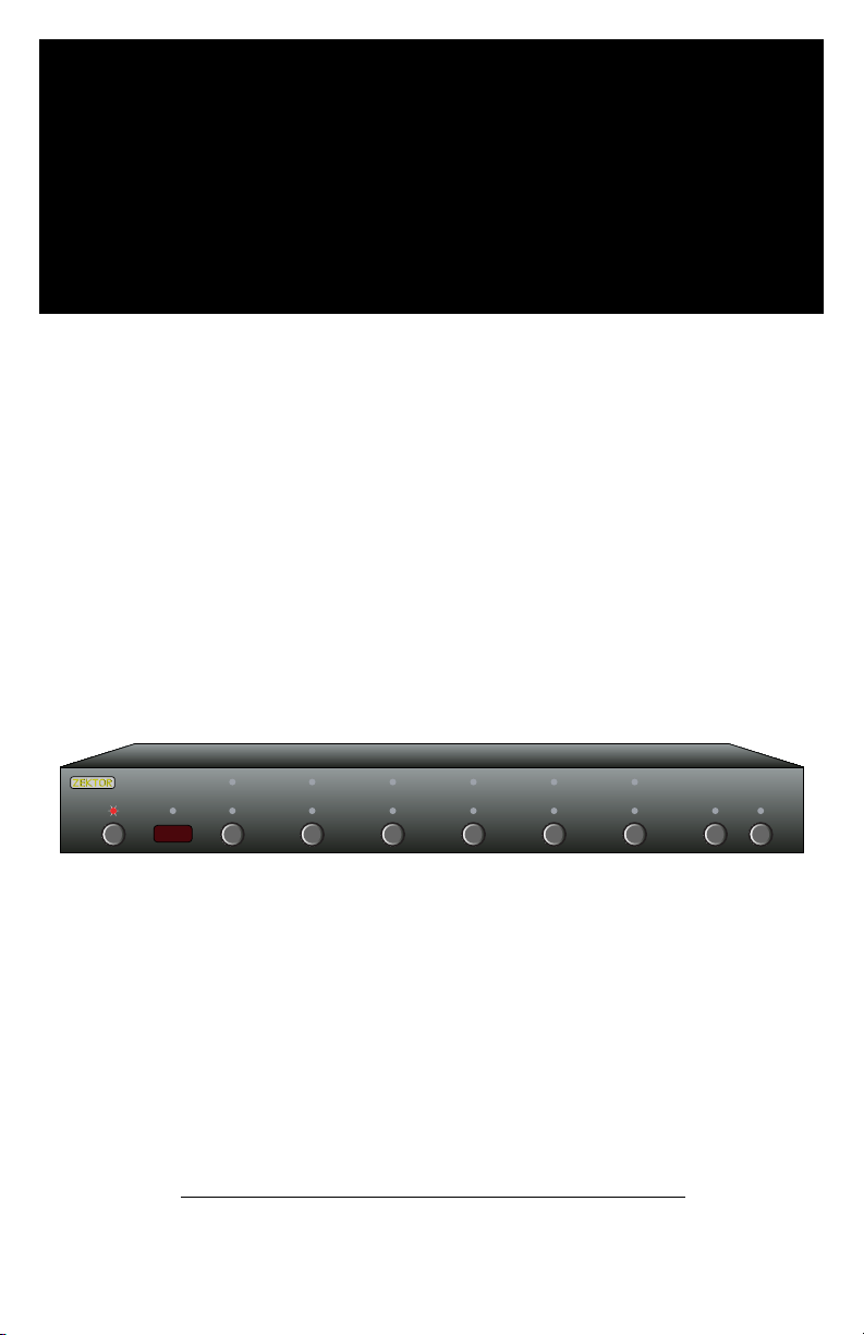
HDVI5
Digital Video Switch
Rev 3 08/08/2006
Page 2

ii HDVI5 Component Video Switch
1HDVI5 Component Video Switch
Contents
What’s Inside
Th a nk y o u fo r y o ur p ur c ha se o f t he H D VI 5 Hi gh De fi ni ti o n Co m po ne nt
Vid eo S w it ch .
What’s Inside ..................................... 1
An Overview of the HDVI5 .................. 3
Easy, Simple, Instructions! ................. 5
Using a Different Remote ................... 9
More Remote Options ...................... 11
Learning New Discrete IR Codes ....... 13
Controlling the Front Panel Lights ... 15
Adjusting the Front Panel Intensity .. 17
Setting the Initial Power On State .... 19
Control Func tions ............................ 21
Changing Switching Delays .............. 23
Input Cable Length Tuning ............... 25
Bandwidth & Sync Settings ............... 27
Auxiliary Relay Options ................... 29
Resetting to Factor y Defaults ........... 35
RS-232 Port ..................................... 36
K.I.S.S.™ (Keep It Simple Serial!™) .... 37
+12V On / Off Control ...................... 38
Rear Panel IR Control ....................... 39
IR Code Format ................................ 40
IR Codes .......................................... 41
Features .......................................... 42
Specifications .................................. 43
Warranty Polic y ............................... 44
Contact Information ........................ 45
Eve ry c ar e h as b e en t ak e n to as su re yo u o f a su c ce ss f ul i ns t al la t io n
an d s ub se qu e nt o pe r at io n o f yo u r ne w H DV I5 vi de o s wi tc h, ho we v er
sh o ul d so me t hi ng g o w ro n g, an d wa r ra nt y r ep ai r w or k i s ne ed e d, w e
re q ue st t h at y o u ho ld on t o t he o r ig in al pa ck ag in g m at e ri al s.
Pl e as e ta k e th is ti me t o v er i fy t he co nt e nt s o f th e H DV I5 b ox.
Th e f ol l ow in g s ho ul d b e in c lu de d:
HD V I5
1.
Re mo t e Co n tr o l (Z RM 1 )
2.
Pow e r Su p pl y Mo du l e
3.
Th i s Us e r’s M an u al
4.
If a nyt hi ng is m is s in g pl e as e ge t i n to u ch w it h u s as so on a s p os si b le
so th at w e c an co rr e ct t he s i tu at io n .
Page 3
2 HDVI5 Component Video Switch
3HDVI5 Component Video Switch
DIGITAL VIDEO
1 2 3 4 5
IR / Z-IN Z-OUT
RS232
1 2 3
4 5 OUT
DIGITAL
AUDIO
1 2 3 4 5 OUT
AUX1 AUX2
9VDC
N/O
COM
COM
N/C
N/O
COM
COM
N/C
1 2 3 4 5 SEL A1 A2
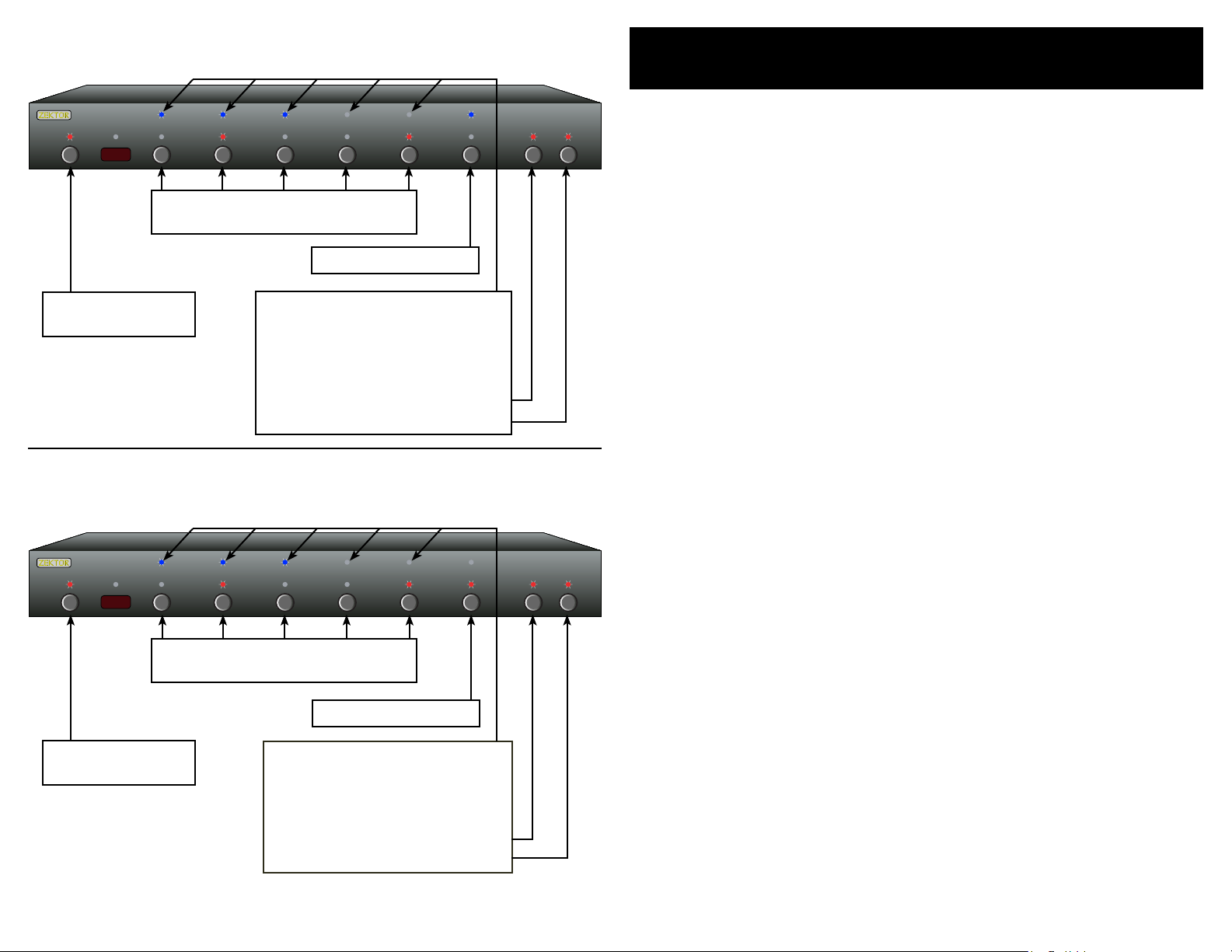
An Overview of the HDVI5
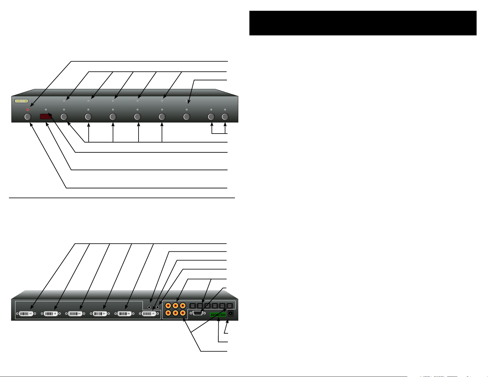
Front Panel
Rear Panel
Front Panel Controls:
Pow e r In di ca t or. Li gh t s up i n s ta nd b y mo d e.
1
2
3
4
5
6
7
8
1
2
3
4
5
6
7
8
9
1.
Se le c ti on L ED s . In di ca t e cu r re nt l y se le c te d in pu t s.
2.
Se le c t be tw ee n N or ma l/ A ud io / Vi d eo B re a ka wa y .
3.
To g gl e Aux il ia r y R el ays .
4.
In pu t S el ec ti on B u tt on s .
5.
In fr a re d R ec ei ve d I nd ic a to r. F l as he s w he n I R is r e ce iv e d.
6.
In fr a re d R em ot e S en so r Wi nd ow.
7.
Pow e r To gg le B ut t on .
8.
Rear Panel Connections:
DV I I np ut s. D VI , o r HD MI wh en u s in g co n ve r si on c a bl e,
1.
co m pa ti bl e d ig i ta l in p ut s. Al l in p ut s ar e f ul l y HD CP co mp at ib l e wi th b o th D VI an d HD M I fo r ma ts . A ll i n pu ts a r e fu l ly
HD M I au di o c om pa t ib le .
IR In pu t or +1 2V Tr ig ge r I np ut . A cc e pt s mo d ul at e d or u n -
2.
mo d ul at e d IR s i gn al s, or + 1 2V Tr ig ge r O n/ Of f vo l ta ge .
DV I O ut pu t ( or H DM I O ut pu t w he n u si ng c o nv e rs io n c ab le ) .
3.
Z- O UT c u rr en t ly u nu s ed , res er ve d f or f u tu re us e.
4.
Di g it al Au di o I np ut s. Ea ch v i de o in p ut h as an a ss o ci at e d
5.
di g it al a u di o ch a nn el w i th b ot h a C o ax a nd an O pt i ca l co n ne c tio n. On ly o n e of t h e tw o t yp es o f i np ut s c an b e a ct iv e
at an y t im e. T he H D VI 5 wi l l au to -s e le ct b et we e n th e t wo
ty pe s o f si gn a ls . I f a si g na l is su pp li e d to bo th t h e Co a x an d
Op t ic al i np u ts , t he C o ax s ig n al i s g iv e n pr io r it y.
RS -2 3 2 Por t.
6.
DC Po w er Ja ck C o nn ec to r.
7.
Au x il ia ry R el ay Co n ne ct io ns .
8.
Di g it al Au di o O ut pu ts . A ll di gi ta l a ud io in pu ts ar e a ut om at-
9.
ic a ll y co n ve r te d to b o th C o ax a nd Op ti ca l o ut pu t s. B o th t he
Co a x an d O pt ic al ou tp ut s a re av ai l ab le s i mu lt an e ou sl y.
Page 4
4 HDVI5 Component Video Switch
5HDVI5 Component Video Switch
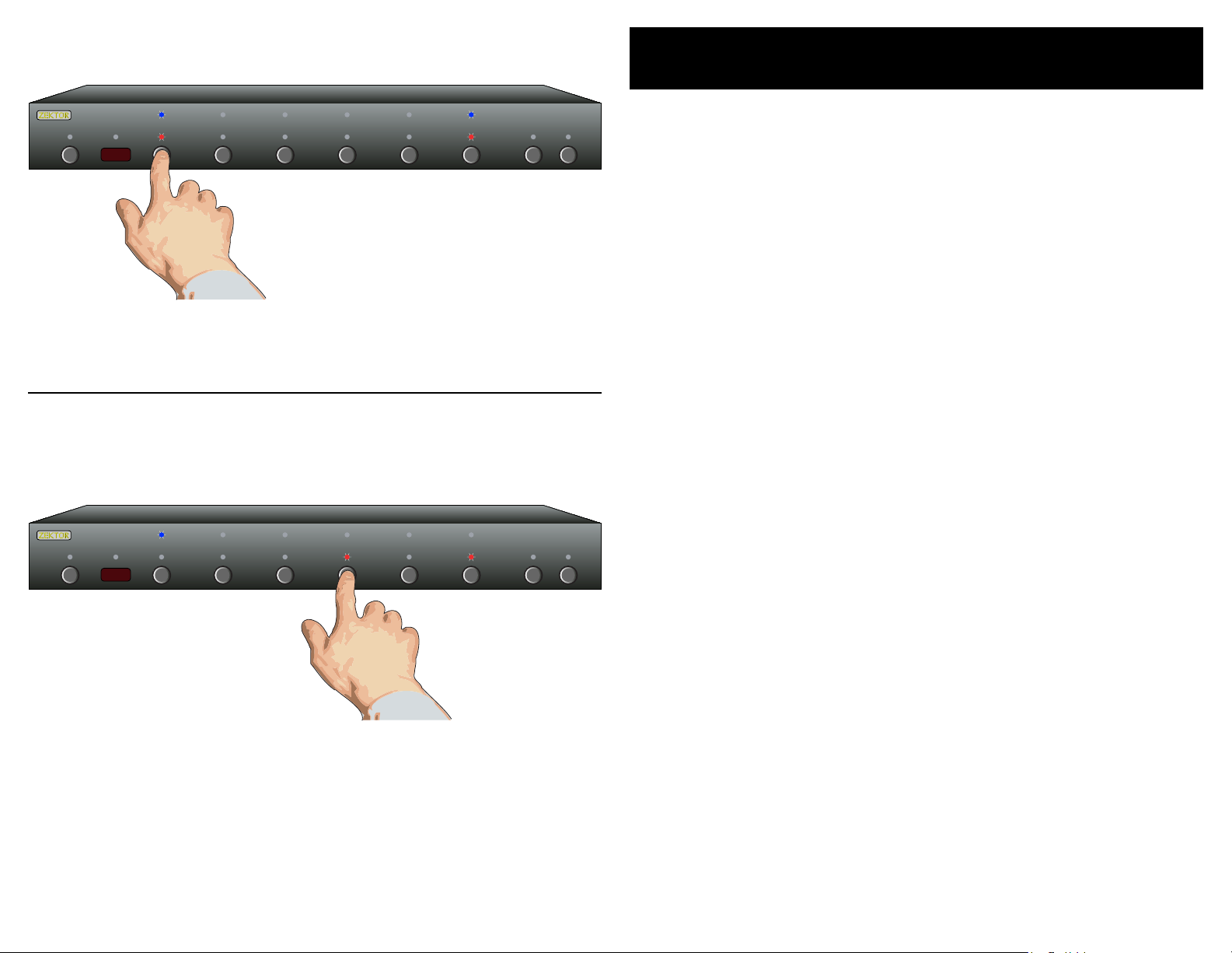
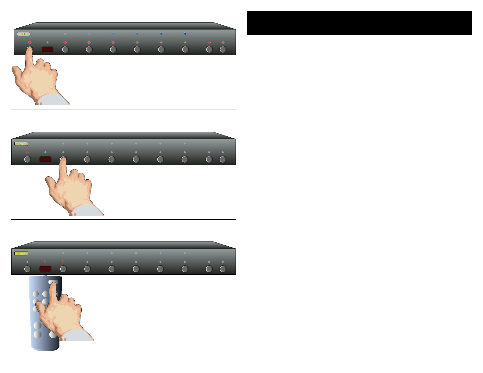
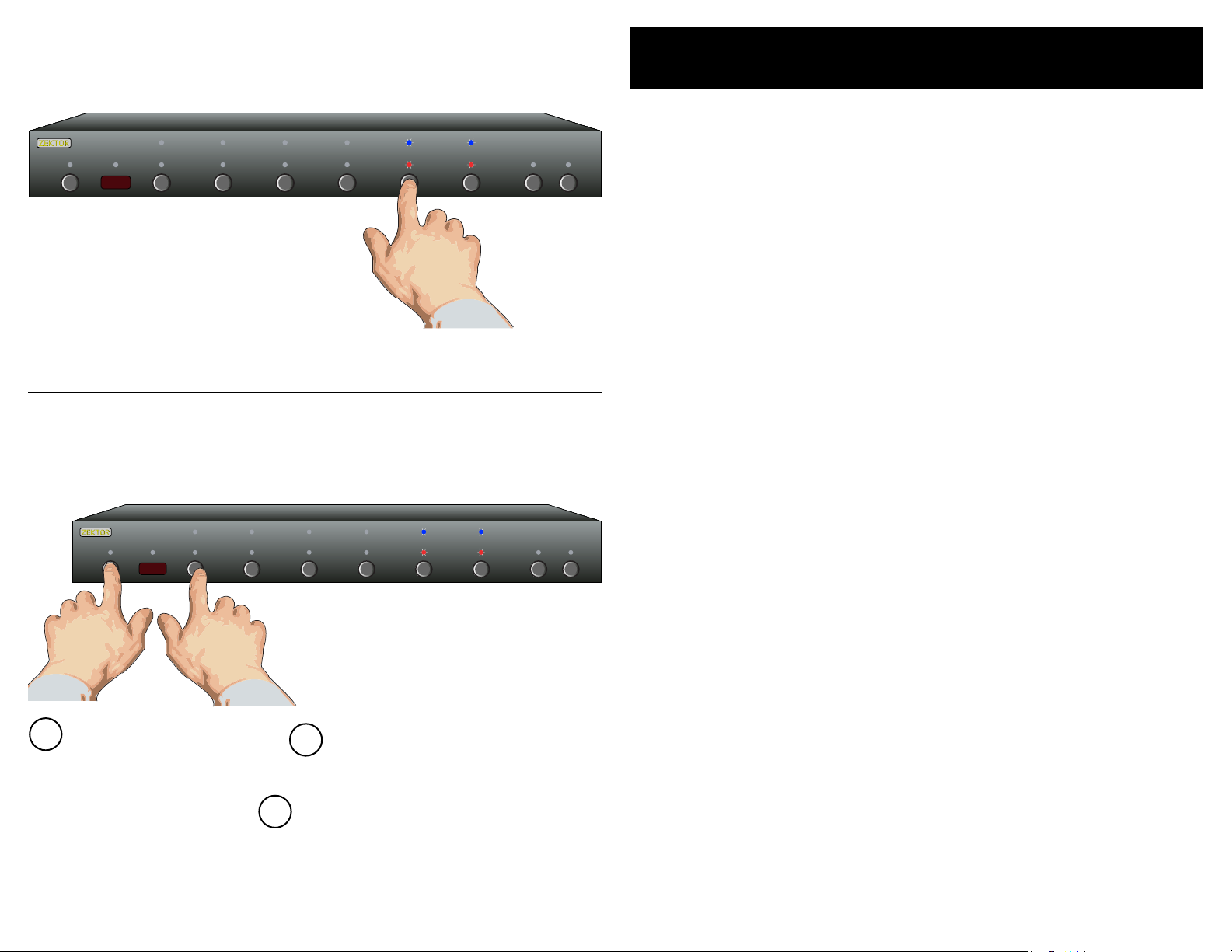
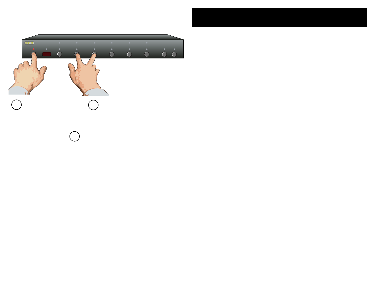
Selecting an Input: Press numbered buttons to select an input.
1 2 3 4 5 SEL A1 A2
1 2 3 4 5 SEL A1 A2
Audio / Video Breakaway: Press SEL to toggle breakaway options.
Easy, Simple, Instructions!
Initial Setup...
Us e t he D V I co n ne ct io ns to s wi t ch D VI (a nd H D MI s ig n al s
•
us i ng t he p r op er co nve rs io n c ab le s ). U s e th e d ig it al au di o
co n ne ct or s t o sw i tc h di g it al a u di o si g na ls , w it h a ut om a ti c
co n ve r si on b e tw ee n t he o pt i ca l an d c oa x d ig it a l au di o
fo r ma ts .
If u si n g a ha r dw ir e d IR co nt r ol le r t o op e ra te th e HD V I5 ,
•
co n ne ct t he co nt r ol le r I R ca bl e t o t he IR / Z- I N ja ck .
If u si n g a PC (o r ot h er s er i al c on t ro l le r) , co n ne ct i t t o th e
•
RS -2 3 2 po r t u si ng a st an d ar d s er ia l c ab le .
Pl u g th e p ow e r mo du l e in to th e HD V I5 , an d p lu g t he m od -
•
ul e i nt o a s ta n da rd A. C. w a ll r e ce pt ac l e. T he s t an db y L ED
wi l l li gh t u p.
Selecting an Input...
To sw it c h be tw e en a ny of t h e fi ve in pu ts, s im p ly p re s s th e
•
bu t to n for t he de si re d i np u t. I f th e H DV I5 is i n t he s ta n db y
mo d e, i t w il l tu r n on . Th e HD V I5 w il l t he n s wi tc h t o th e s ele c te d in pu t , an d t he a ss o ci at e d LE Ds wi ll l i gh t to in di c at e
th i s.
To pl ac e t he H D VI 5 ba c k in to th e st a nd by mo de , p re s s an d
•
re l ea se t h e Pow e r Tog gl e b ut to n . T h e ch an n el L ED s w il l a ll
go bl an k, a n d th e s ta nd by LE D w il l li g ht u p . P re s s th e P owe r
To g gl e bu t to n ag a in t o r e - se le ct t h e pr e vi ou sl y s el ec te d
in p ut .
Only red LED, above
the SEL button is lit,
so only Audio is
switched when
'4' is pressed.
Audio / Video Breakaway...
To br ea k aw ay t h e au di o o r vi d eo , t o li s te n t o th e a ud io
•
fr o m on e i np ut w h il e vi e wi ng v i de o fr o m an o th er, pr e ss
th e S EL k ey. W he n b ot h th e R ED a n d BLU E L ED s ab o ve th e
SE L b ut to n a re li t, t h en t he au di o a nd v id e o in pu t s wi ll be
sw i tc he d s im ul ta n eo us ly. W he n o nl y th e R ED L E D is l i t, t he n
on l y th e Aud io w i ll b e s wi tc h ed . S im il ar ly, wh en o n ly t he
BLU E L ED i s l it , o nl y th e v id eo wi ll b e s wi tc h ed w he n p re s sin g a n in pu t b ut to n .
No t e: Au di o br e ak aw ay on ly a pp li es t o th e di gi ta l a ud io c on -
ne c tio ns o n th e ba ck of t he H DV I5 . Yo u c an no t br ea kawa y t he H DM I au di o ch an ne l th at is s en t ov e r th e HD MI
ca bl e. HD MI a ud io w i ll a lw ays f ol low t he v id eo s ig na l.
Page 5
6 HDVI5 Component Video Switch
7HDVI5 Component Video Switch
1 2 3 4 5 SEL A1 A2
152 3 4
1 2 3
S1
S2 S3
A1 A2
SYN
SEL
HDVI5/HDMI5
MAS7
CVS4
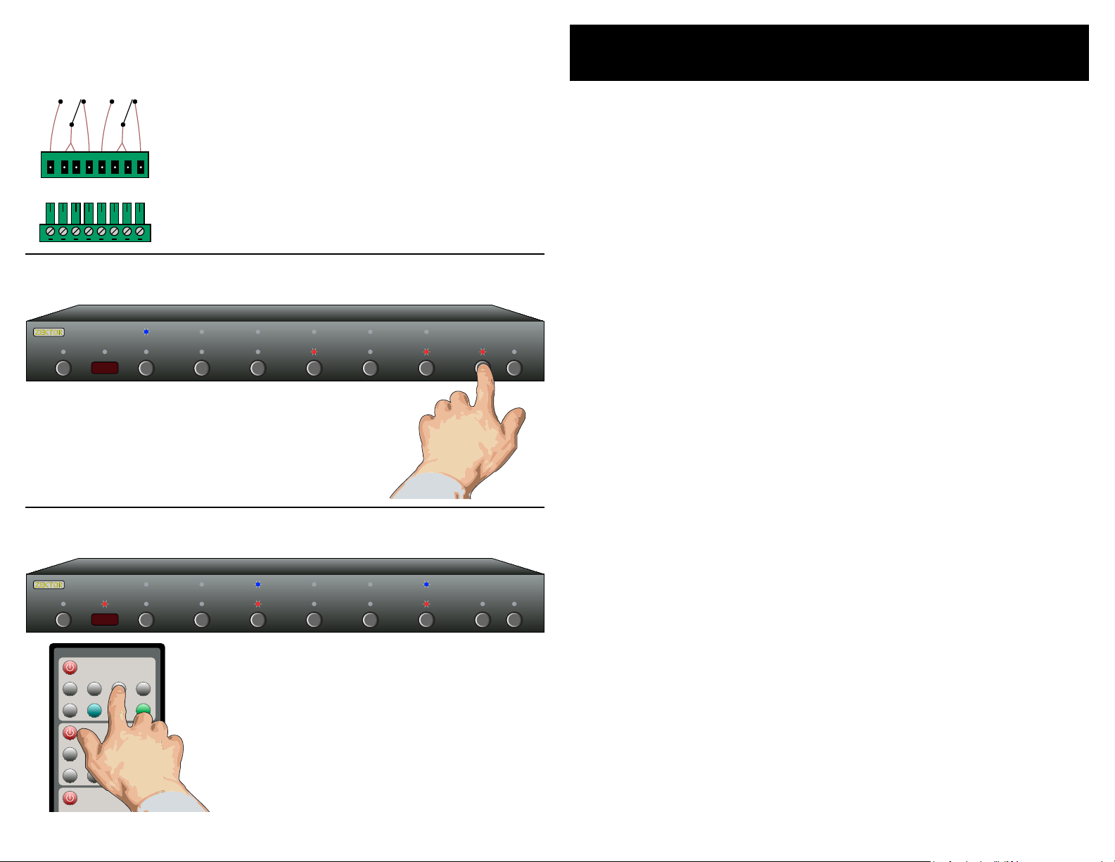
Auxiliary Relay Connections
1 2 3 4 5 SEL A1 A2
N/O
COM
COM
N/C
N/O
COM
COM
N/C
Relay 1’s
Contacts
Relay 2’s
Contacts
N/O = Normally Open Contacts. These contacts
are open when the relay's LED is not lit.
COM = Common
N/C = Normally Closed Contacts. These contacts
are closed when the relay's LED is not lit.
Make connections to the adapter which plugs into the HDVI5.
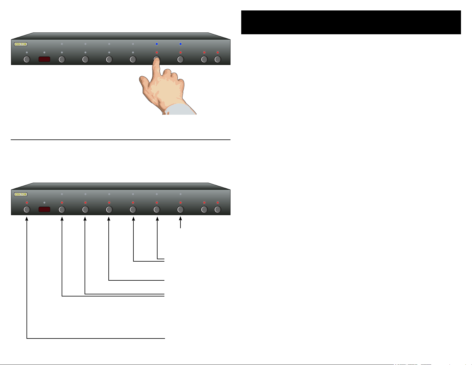
Auxiliary Relay Operation: Use A1 and A2 buttons to toggle relays.
Instructions (Cont'd)
Auxiliary Relay Connections
Th e a ux il i ar y re la y c on t ac ts a re ra t ed f o r 30 vol ts @ 5a mp s,
•
A. C . or D. C ., a nd ca n be u s ed t o s wi tc h o n an d o ff a n yt hi n g
yo u c an t h in k of wi th in th os e l im it s.
Ea c h re l ay h a s a No rm a ll y Op e n co n ne ct io n, t wo Co m mo n
•
co n ne ct io ns , a nd a No rm al l y Cl os e d co n ne ct io n.
Th e d ia gra m to th e le f t de mo ns t ra te s t he i n te rn al co nn e c-
•
ti o ns t o t he r e la ys.
By u s in g th e s up pl i ed a da p te r, t he re la y s co n ne ct io ns ca n
•
be ma de b efo re ra ck m o un ti ng th e HD V I5 .
Auxiliary Relay Operation
Th e A 1 an d A 2 bu t to ns a r e us e d to to gg le on a nd of f th e
•
re l ay s .
Th e r el a ys c a n al so be s et u p to tu rn o ff af te r a g iv e n
•
am o un t of ti me . O r to tu rn o n w he ne v er s p ec if ie d c ha nn el s
ar e s el ec te d . Se e t he s ec ti o n "Au xi li ar y Rel ay Op ti on s" f or
re l ay s e tu p in f or ma t io n.
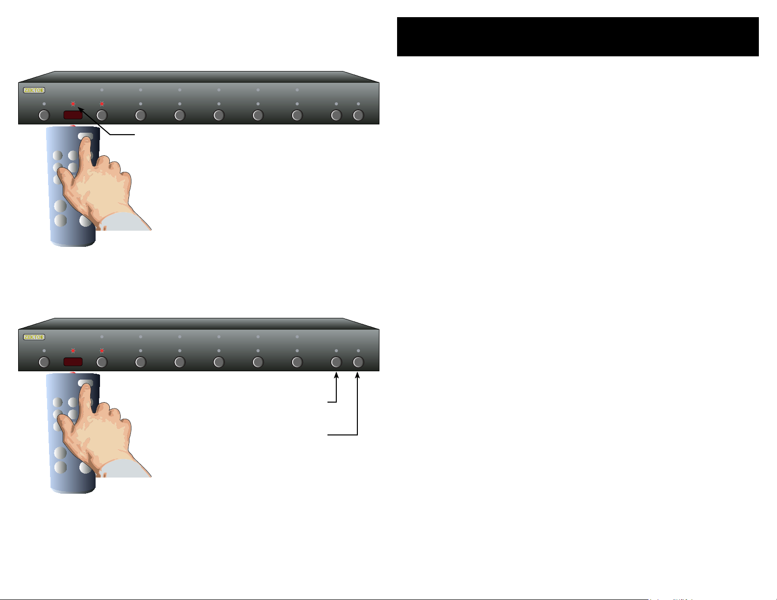
Using the supplied Remote Control
Use the remote controller buttons in the section
labeled: HDVI5 / HDMI5. (The other sections control
other Zektor products)
Each button on the remote corresponds to the
same button on the HDVI5's front panel.
Using the supplied Remote Control
Us e t he s e ct io n of th e re m ot e c on tr o ll ed la be le d : HD VI 5 /
•
HD M I5 f o r co n tr ol l in g th e H DV I5 . ( The o th e r se ct io n s ar e
us e d to c o nt ro l o th e r Ze k to r pr o du ct s) .
Ea c h bu tt o n on t h e re m ot e fu n ct io ns t h e sa me as t he fr on t
•
pa n el s wi tc h w it h t he s a me n am e .
Page 6
8 HDVI5 Component Video Switch
9HDVI5 Component Video Switch
1 2 3 4 5 S EL A1 A2
Step 1: Put the HDVI5 into the Setup Mode
1 2 3 4 5 SEL A1 A2
1 2 3 4 5 SEL A1 A2
1 2 3
4 5 6
7 8 9
0
+ +
_ _
POWER
VOL
CH
Press and hold the Power Button for 4 secs.
The front panel LEDs will start to blink
wildly... (You’ll know it when it happens!)
Step 2: Press the ‘1’ button for Intelligent-IR™ learning
Once the 1 button is pressed, the
standby LED will flash slower, and
all the other LEDs will turn off.
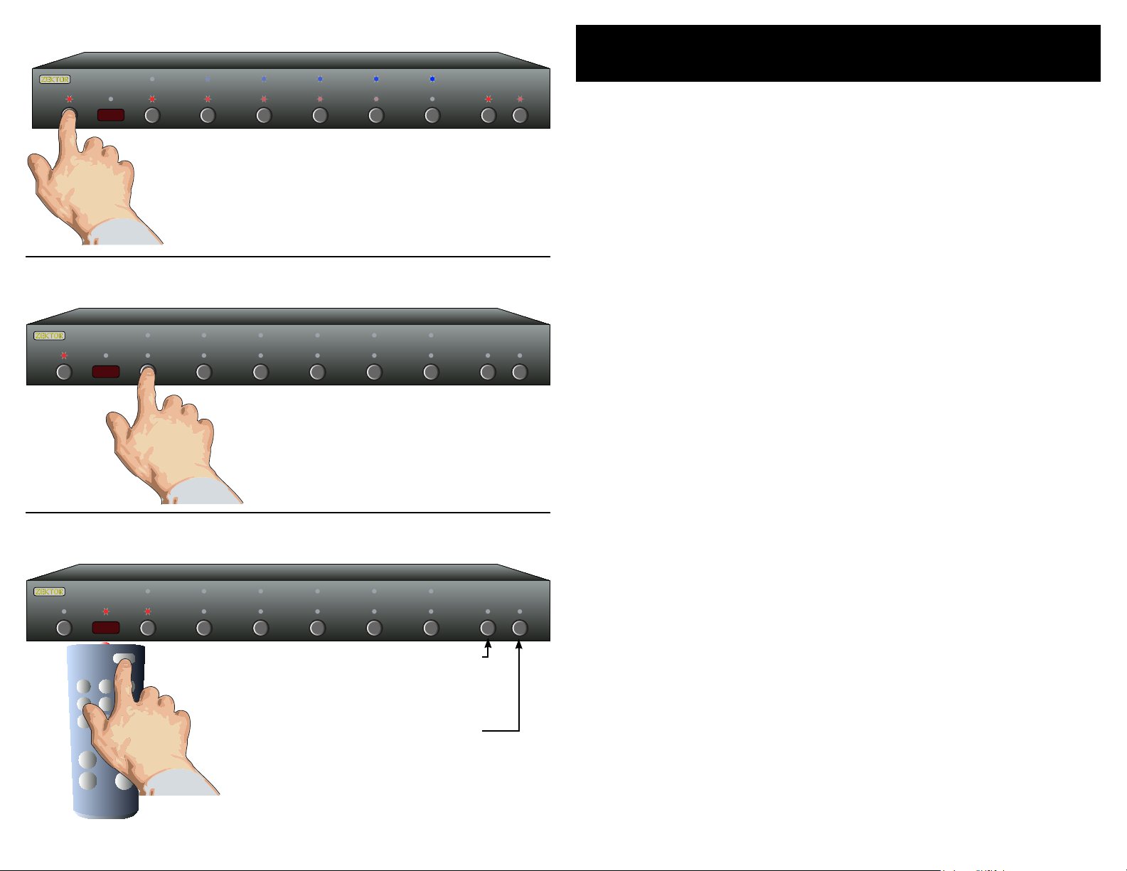
Using a Different Remote
Th e H DV I5 fe at u re s Z ek to r ’s E xc lu s iv e I nt el li g en t- I R™ , an d w it h ver y
fe w e xce pt io n s ca n b e se tu p t o us e a ny re mo t e yo u c an p o in t at it !
Th i s is u s ef ul i f y ou ha ve mo re th an o n e HD VI 5 i n th e s am e r oo m.
Pick a new remote
St a rt by pi ck in g a n ew r e mo te yo u’d li ke t o u se w i th t he
•
HD V I5 . (O r u se t h e un us e d bu tt o ns o n t he H DV I 5' s rem ot e .)
If y o u pl an on u si n g a un i ve rs a l re m ot e, st ar t by se tt in g
•
it up a s a r em ot e f o r a T V or VC R t ha t y ou d o n' t ow n. (F o r
in s ta nc e i f yo u d on’ t o wn a So ny T V, se tu p y ou r u ni ve r sa l
re m ot e t o co n tr ol a So ny T V. )
Step 1: Put the HDVI5 into the Setup Mode
Th e H DV I5 is p la c ed i nto t he se tu p m od e by pr e ss in g an d
•
ho l di ng t he Pow er bu tt o n fo r a bo ut 4 se co n ds .
Step 2: Select the Intelligent-IR™ Learn Mode
Se le c t th e In te l li ge nt - IR ™ L ea rn M o de p re s si ng ‘1 ’.
•
On c e th e ‘ 1’ bu tt o n is p r es se d , th e s ta nd b y LE D w il l fl a sh
•
sl o we r a nd a ll th e ot h er L ED s w il l t ur n of f. Th e H DV I5 i s
no w w ai ti n g fo r n ew I R c od e s to b e s en t f ro m y ou r r em ot e
co n tr ol.
Step 3: Teach the HDVI5 its new IR codes
Press the following sequence of buttons on
your remote control:
Power 1 2 3 4 5 0 8 9
That’s it! The HDVI5 now operates with
your new remote control!
Step 3: Teach the HDVI5 your new remote control codes
On yo ur re mo te co nt r ol , p re s s th e f ol lo w in g b ut to ns, i n t he
•
fo l lo wi n g or d er :
Powe r 1 2 3 4 5 0 8 9
Th e f ro n t pa ne l L ED 's wi ll s e qu en ce as e ac h b ut to n i s
•
pr e ss ed , a nd t h e IR L E D wi ll fl as h f or e a ch b ut t on - - i f no t,
se e t he f o ll ow i ng s ec ti o n on " Mo re Re mo te Opt io ns".
Th a t’s it ! T h e HD V I5 w il l r et ur n t o th e s ta t e it w a s in b e fo r e
•
se t up , a nd w i ll n ow wo rk wi th y o ur n ew re mo t e!
e new control buttons on your remote are...
Powe r To g gl es t h e HD VI 5 ’s p owe r.
1 - 5 Se le ct s i np ut s 1 t hr ou g h 5.
0 Se qu e nc es t h e SE L b ut to n ( A/ V b re a kaw a y) .
8 To g gl es Au xi li a ry Re la y 1 .
9 To g gl es Au xi li a ry Re la y 2 .
No t e: Al l re mo te co nt ro l c od es a re sa ve d i n no n- vo la t il e
me m or y a nd w il l no t be lo st d ur in g a po wer f ai lu re.
Page 7
10 HDVI5 Component Video Switch
11HDVI5 Component Video Switch
1 2 3 4 5 SEL A1 A2
1 2 3
4 5 6
7 8 9
0
+ +
_ _
POWER
VOL
CH
1 2 3 4 5 SEL A1 A2
1 2 3
4 5 6
7 8 9
0
+ +
_ _
POWER
VOL
CH
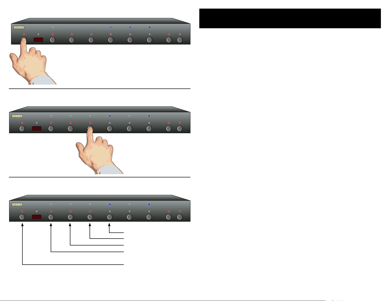
Front panel LED sequencing while learning
The IR LED will flash...
...and the LEDs will sequence each time a
remote control button is pressed if the IR
code is compatible with the HDVI5.
Skipping or Deleting IR codes
More Remote Options
Front panel LED sequencing while learning
Du r in g th e l ea rn in g p ro c es s, as e ac h b ut to n o f t he r e mo te i s
pr e ss ed , t he f r on t p an el L E Ds w il l s eq ue n ce . A t a ny g i ve n t im e, th e
LE D t ha t i s sl ow l y fl as h in g, in di ca t es t h e fu nc ti o n th e HD V I5 i s c ur re n tl y w ai ti ng to l ea r n. Th e s eq ue n ce i s :
St a nd by L ED Wai t in g fo r Po we r To gg l e IR c o de .
'1 ' - R ed L ED Wai t in g fo r t he '1 ' IR c o de .
'2 ' - R ed L ED Wai t in g fo r t he '2 ' IR c o de .
'3 ' - R ed L ED Wai t in g fo r t he '3 ' IR c o de .
'4 ' - R ed L ED Wai t in g fo r t he '4 ' IR c o de .
'5 ' - R ed L ED Wai t in g fo r t he '5 ' IR c o de .
'S E L' Re d LE D Wai t in g fo r ' SE L' IR co de .
'A 1' L ED Wai t in g fo r 'A1 ' IR co de .
'A 2' L ED Wai t in g fo r 'A2 ' IR co de .
If t he LE Ds d o n ot s e qu en ce, a nd th e IR LE D do e s no t f la sh , w he n a
bu t to n is pr es s ed o n t he r e mo te , t he n t he H DV I 5 do es no t rec og n iz e
th e I R co d e be in g s en t . Ma ke s u re t h e re m ot e' s b at te r ie s ar e f re s h.
Th e H DV I5 wi ll wo rk w it h m os t r em ot e s, ho we v er t h er e a re a fe w
ex c ep ti o ns . S om e te c hn ic al re as o ns f o r no t w or k i ng w i th s om e r emo t es a re : Th e r em o te m a y be u s in g a c ar ri er f r eq ue n cy ou t si de t h e
ra n ge o f t he H DV I 5 (3 4K H z to 4 2K H z) , or i t m ay be u si n g on e o f th e
fe w p ro t oc o ls t he HD VI 5 d oe s no t u nd er st a nd , l ik e th e P hi li p 's R C 5
an d R C6 p rot oc o ls .
Disable current IR code
Skip current code
(Leave IR unchanged)
If t he HD VI 5 d oe s no t l ea rn th e re m ot e c od es yo u ar e u si n g, y o u
wi l l ha ve to us e an o th er r e mo te, o r i n th e c as e of us in g a u ni ve r sa l
re m ot e, yo u 'l l ha v e to pi ck a di ff e re n t ma nu f ac tu re r 's c o de .
Skipping or Deleting IR codes
Du r in g th e I R le ar n in g pr o ce ss yo u c an c ho o se t o d el et e t he c u rr en t
co d e (d is a bl e IR fo r t ha t fu n ct io n) o r s ki p th e c ur re n t co d e (l ea v e it
un c ha ng ed ) b y pr e ss in g t he 'A1 ' o r 'A2 bu tt o ns :
'A 1' Di s ab le IR f o r cu rr e nt f u nc ti on .
'A 2' Sk ip cu rr e nt c o de , l ea ve it u nc h an ge d.
Page 8
12 HDVI5 Component Video Switch
13HDVI5 Component Video Switch
1 2 3 4 5 S EL A1 A2
Step 1: Put the HDVI5 into the Setup Mode
1 2 3 4 5 SEL A1 A2
1 2 3 4 5 SEL A1 A2
1 2 3
4 5 6
7 8 9
0
+ +
_ _
POWER
VOL
CH
Learning New Discrete IR Codes
Th e H DV I5 al lo w s di sc r et e I R co n tr ol ov e r al l o f it 's fu nc ti on s . T h es e
co d es c an al so b e r ep r og ra m me d as de sc ri b ed h er e .
Press and hold the Power Button for 4 secs.
The front panel LEDs will start to blink wildly.
Step 2: Press the '2' button for Intelligent-IR™ learning
Once the 2 button is pressed, the
HDVI5 will be ready to learn new
discrete IR codes starting with
"Discrete Power On".
Step 3: Teach the HDVI5 its new IR codes
Press the buttons on your
remote, that you want to
use as the new discrete IR
codes, in the order given
in "Step 3" of the text.
Disable current
IR code and
skip to next
Skip current IR
code (leave it
unchanged)
Pick a remote
St a rt by pi ck in g th e r em o te y o u’d l ik e t o u se w it h t he
•
HD V I5 . (U nu s ed b ut t on s o n th e s up pl ie d r em ot e w o rk f in e.)
Step 1: Put the HDVI5 into the Setup Mode
Th e H DV I5 is p la c ed i nto t he se tu p m od e by pr e ss in g an d
•
ho l di ng t he Pow er bu tt o n fo r a bo ut 4 se co n ds .
Step 2: Select the Intelligent-IR™ Learn Mode
Di s cr et e I R le a rn in g is se le ct ed by p r es si n g th e '2 ' b ut to n .
•
On c e th e ' 2' b ut t on i s p re ss e d, t h e st an d by L ED wi ll f l as h
•
sl o we r a nd a ll th e ot h er L ED s w il l t ur n of f. Th e H DV I5 i s
no w w ai ti n g fo r n ew I R c od e s to b e s en t f ro m y ou r r em ot e
co n tr ol.
Step 3: Teach the HDVI5 your new discrete IR control codes
On yo ur re mo te co nt r ol , p re s s th e b ut to n s yo u 'd l ik e t o u se
•
as di sc re t e IR co de s , in t h e fo l lo wi n g or d er :
Powe r On - Tu rn s On Pow er
Powe r Of f - Tur ns O ff Po w er
Se qu en ce I np ut s - S eq ue nc e t hr o ug h in p ut s
No Br ea ka wa y - Re se t s au di o /v id eo br ea ka way
Br e ak aw ay Au di o - S et s au di o b re a ka wa y m od e
Br e ak aw ay V i de o - S et s vi d eo b re a ka wa y m od e
Aux R el ay 1 O n - Tur ns o n A ux Re la y 1
Aux R el ay 1 O ff - Tur ns o f f Au x R el ay 1
Aux R el ay 2 O n - Tur ns o n A ux Re la y 2
Aux R el ay 2 O ff - Tur ns o f f Au x R el ay 2
Th e n ew c o de s a re l ea r ne d in th e ab o ve o r de r, f o r in st a nc e
•
th e f ir st b u tt on yo u pre ss , o n th e r em o te , w il l b e us e a s th e
ne w d is cr e te " P owe r On ", t h e se co n d bu tt o n pr e ss ed w i ll b e
us e d as t he ne w "Po w er O ff ", et c.
Th e 'A 1 ' ca n b e pr e ss ed t o d is a bl e th e c ur re n t IR co de .
•
Th e 'A 2 ' ca n b e pr e ss ed t o s ki p th e c ur re n t IR co de , l ea v in g
•
it un ch an ge d .
No t e: Al l re mo te co nt ro l c od es a re sa ve d i n no n- vo la t il e
me m or y a nd w il l no t be lo st d ur in g a po wer f ai lu re.
Page 9
14 HDVI5 Component Video Switch
15HDVI5 Component Video Switch
1 2 3 4 5 S EL A1 A2
Step 1: Place the HDVI5 into the Setup Mode
1 2 3 4 5 SEL A1 A2
1 2 3 4 5 SEL A1 A2
Press and hold the Power Button until the
display goes wild. (About 4 seconds.)
Step 2: Select “Lighting Mode” option
Controlling the Front Panel Lights
Th e re a r e fo u r di f fe re n t fr o nt p a ne l li g ht in g m od es a v ai la b le o n t he
HD V I5 . T h ey a re :
Fro n t pa ne l l ig ht s a ut o ma ti ca l ly f ad e f ro m b ri gh t t o d im
•
af te r 4 s ec o nd s of in ac ti vi t y.
Fro n t pa ne l l ig ht s a re al wa y s at th e br i gh t le v el .
•
Fro n t pa ne l l ig ht s a re al wa y s at th e di m l ev e l.
•
Fro n t pa ne l l ig ht s a re tu rn ed of f.
•
No t e: Th e i nt e ns it ie s o f th e b ot h t he b ri g ht a nd di m le v el s c an b e
ad j us te d a s we l l. T hi s i s ex pl a in ed o n t he n e xt p ag e.
To ch an ge th e fr o nt p a ne l li g ht in g m od e. . .
Step 1: Enter the Setup Mode
Th e H DV I5 is p la c ed i nto t he se tu p m od e by pr e ss in g an d
•
ho l di ng t he Pow er bu tt o n fo r a bo ut 4 se co n ds .
Step 3: Choose a new lighting mode
After ‘3’ is pressed, the standby
LED continues to flash, and the
front panel will display the current Light Mode settings.
Auto-Fade
Always Bright
Always Dim
Always Off
Exit Setup Mode
Step 2: Select the Lighting Mode option
Pre ss th e ‘ 3’ bu tt o n to se le ct t he “L ig ht i ng M od e ” o pt io n .
•
Th e f ro n t pa ne l s el ec ti o n LE Ds no w in d ic at e t he c u rr en t ly
•
se l ec te d li g ht m od e a s fol lo w s:
If ‘ 1 ’s b lu e L ED i s l it , t he n fro nt p a ne l li g ht s are a lw a ys of f.
If ‘ 2 ’s b lu e L ED i s l it , t he n fro nt p a ne l is al wa y s di m .
If ‘ 3 ’s b lu e L ED i s l it , t he n fro nt p a ne l is al wa y s br ig h t.
If ‘ 4 ’s b lu e L ED i s l it , t he n fro nt p a ne l li g ht s au t o- fa de f r om
br ig h t to di m af te r 4 s ec o nd s o f in ac ti v it y.
Step 3: Choose a new lighting mode
Ch o os e a ne w l ig ht co nt r ol m o de b y p re s si ng t h e as so c i-
•
at e d se le c ti on b ut t on .
Pre ss th e Pow e r Bu tt o n to sa ve th e ne w m od e a nd r e tu rn t o
•
no r ma l op er a ti on s .
No t e: Th e li gh ti n g mo de s et ti ng i s sa ved i n no n- vo l at il e me m-
or y an d is n ot a ff e cte d b y a po wer f ai lu re.
Page 10

16 HDVI5 Component Video Switch
17HDVI5 Component Video Switch
1 2 3 4 5 SEL A1 A2
Step 4: Select between Bright and Dim settings: Use SEL button.
1 2 3 4 5 SEL A1 A2
1 2 3 4 5 S EL A1 A2
Use the SEL button to toggle between
the BRIGHT and DIM settings.
Step 5: Adjust Front Intensities.
Use A1 and A2 to dim and brighten LEDs
A1 = Dim LEDs.
A2 = Brighten LEDs.
Adjusting the Front Panel Intensity
Continued from previous page...
If y o u ha v e no t a lr e ad y do n e so, p er fo r m St ep s 1 a nd 2 on t h e pr e vi ou s p ag e.
Step 4: Toggle between Bright and Dim Settings
Th e ' SE L' L ED i nd i ca te s t he f r on t p an el i n te ns i ty s et ti n gs :
•
If B LU E LE D i s li t, th en t h e BR IG H T le ve l i s b ei ng a d ju st ed .
If R ED LE D is li t, t h en t he DI M le v el i s b ei ng ad ju st e d.
Us e t he ' S EL' b ut t on t o t og gl e b et we e n br ig h t an d d im
•
se t ti ng s.
Step 5: Adjust Front Panel Intensities
Us e t he ‘A 1’ bu tt o n to de cr e as e th e i nt e ns it y of th e fro nt
•
pa n el l ig ht s .
Us e t he ‘A 2’ bu tt o n to in cr e as e th e i nt e ns it y of th e fro nt
•
pa n el l ig ht s .
Yo u c an no t m ak e t he D IM le ve l b ri gh t er t ha n t he B R IG HT
•
le v el , a nd y o u ca nn o t ma ke th e BR I GH T le v el d i mm er t h an
th e D IM l eve l.
Step 6: Use the Power Button to Exit.
When things look good, press the
power button to exit the setup mode.
Step 6: Use the Power Button to Exit
On c e th e f ro nt pa ne l i nt en s it ie s a re a c ce pt a bl e, pr es s t he
•
Pow e r bu t to n to sa ve th e n ew s et t in gs a n d ex it th e se t up
mo d e.
No t e: Th e ne w in t en si ty s et ti ng s ar e s av e d in n on -v ol at i le
me m or y a nd a re no t af fe ct ed b y a po w er f ai lu re.
Page 11
18 HDVI5 Component Video Switch
19HDVI5 Component Video Switch
1 2 3 4 5 SEL A1 A2
Step 1: Set the HDVI5 to the preferred initial power on state
1 2 3 4 5 SEL A1 A2
Setup the HDVI5 to the initial power on
state you’d prefer. In this case we want the
HDVI5 to turn on and switch to Input 5
when first plugged in.
Setting the Initial Power On State
As lo ng a s t he H D VI 5 is pl ug ge d i n, i t w il l r em em b er t he p r ev io u sl y
se l ec te d in p ut i n s ta nd by mo de . Wh en po we r ed u p b y p re ss in g t he
Pow e r bu t to n, i t w il l r et ur n t o th a t pr e vi ou sl y s el ec te d c ha nn e l.
Ho w ev e r, i f po w er i s r em ove d (fo r in s ta nc e a p lu g s tr ip u s ed t o p ow er th e HD VI 5 i s tu r ne d of f ) , an d t he n re -a pp l ie d, th e HD V I5 ’s de fa ul t
be h av io r i s to en te r i nt o t he s t an db y m od e.
It i s p os si bl e t o ch a ng e th e p ow e r on be ha vi o r of t h e HD VI 5 .
To ch an ge th e po w er o n d ef au l ts .. .
Step 2: Save the new initial power on state
1
Start by pressing and
holding the Power
button...
2
...while continuing to hold the Power
button, press and hold the ‘1’ button.
Step 1: Setup the HDVI5 to your preferred power on state
Us e t he f r on t p an el b u tt on s t o se t up t he HD VI 5 t o th e o pe r-
•
at i ng s et t in gs y o u’d l ik e a t in i ti al p o we r u p.
Step 2: Save the new initial power on state.
Fir st pr es s a nd h ol d t he Po w er b u tt on .
1.
Wh i le c o nt in ui n g to ho ld t h e Pow e r bu tt o n, p res s an d h ol d
2.
th e ‘1’ bu tt o n.
Af te r h ol di n g bo th bu tt o ns f o r ab ou t ‘4 ’ se c on ds , t he d i s-
3.
pl a y wi ll bl in k i nd ic at i ng t he ne w po w er o n d ef au l ts h ave
be e n ac ce p te d.
Test the new initial power on state
Yo u c an t e st t he ne w de f au lt s b y ei t he r di s co nn ec ti n g th e
•
po w er s u pp ly f r om t h e ba ck of t he HD VI 5 or by u n pl ug gi n g
th e p ow e r su pp l y fr o m th e w al l.
Re co n ne ct p owe r. Th e H DV I5 wi ll p o we r u p in t o yo u r ne w
•
po w er o n d ef au l t st at e .
.
3
After about 4 seconds, the display will
flash indicating the new power on state
has been accepted.
Page 12

20 HDVI5 Component Video Switch
21HDVI5 Component Video Switch
1 2 3 4 5 SEL A1 A2
1 2 3 4 5 S EL A1 A2
Step 1: Place the HDVI5 into the Setup Mode
1 2 3 4 5 SEL A1 A2
Control Functions
If y o u ar e u si ng th e re a r pa n el I R j ac k, y o u mi gh t w an t t o d is ab le t h e
IR se ns or s t o pr e ve n t us e o f th e r em ot e c on t ro l.
Press and hold the Power Button until the
display goes wild. (About 4 seconds.)
Step 2: Enter the Enable / Disable control state
After ‘4’ is pressed, the standby
LED continues to flash, and the
front panel will display the current settings.
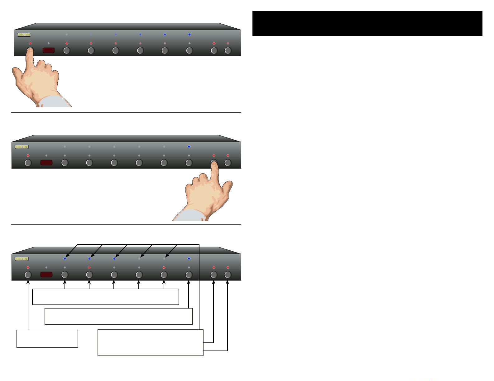
Step 3: Enable or Disable control functions
Or if y o u ha v e a ho u se ho ld wi th y o un g c ur io us f i ng er s t ha t li k es
pl a yi ng w i th b ut t on s, yo u a ls o hav e t he c ap a bi li ty o f d is ab li n g th e
fr o nt p a ne l sw i tc he s a nd o nl y o pe ra t in g t he H DV I 5 wi th a re m ot e.
To en ab le / di sa b le t he fr on t p an el sw it c he s, an d ot h er c on t ro l
fu n cti on s .. .
Step 1: Enter the Setup Mode
Th e H DV I5 is p la c ed i nto t he se tu p m od e by pr e ss in g an d
•
ho l di ng t he Pow er bu tt o n fo r a bo ut 4 se co n ds .
Step 2: Enter the Enable / Disable control state
Wh i le i n t he s et u p mo de , p re s s '4 ' t o en t er t h e En ab l e/ Di s-
•
ab l e co nt r ol s t at e. T he cu rr e nt s ta t us w il l b e di s pl ay e d us in g t he f ron t pa n el L ED s .
A B lu e LE D i nd ic ate s an op ti on is e na b le d, an d Re d L ED
•
in d ic at e s di sa b le d.
Step 3: Enable or Disable control functions
Us e ' 1' t o e na bl e /d is ab l e th e I R Se ns o r ha rd w ar e .
•
Us e ' 2' t o e na bl e /d is ab l e th e I R Ja ck ha rd w ar e.
•
Us e ' 3' t o e na bl e /d is ab l e th e f ro nt pa ne l b ut to n s.
•
Us e ' 4' t o e na bl e /d is ab l e IR c o nt ro l .
•
Us e ' 5' t o e na bl e /d is ab l e +1 2V On /O ff c o nt ro l .
•
No t e 1: T he I R Ja ck a nd +1 2V O n/ Off c o nt ro l fu nc ti on s ar e m ut u-
al l y ex c lu si ve . E na bl in g +1 2V O n/ Of f co nt r ol w il l di sa bl e
th e I R Ja ck h ar dw a re . En ab l in g IR J ac k ha rd wa r e wi ll d is ab l e +1 2V O n/ Off co nt ro l .
Enable/Disable +12V Ctrl.
Enable/Disable IR Control
Enable/Disable Buttons
Enable/Disable IR Jack
Enable/Disable IR Sensor
Exit Setup Mode
No t e 2: W he n di sa bl in g th e IR J a ck a nd I R Se ns or, th e ha rd -
wa r e is d is ab le d. W he re as ' IR Co nt r ol ' en ab le s/ di sa bl es
wh e th er t he H DV I5 r es p on ds t o IR s ig na ls r e ce iv e d. I f
th e I R Sen so r o r IR J ac k ar e e na bl ed , an d 'I R Con tr o l'
di s ab le d, I R si gn al s ca n st il l b e re ad t hr ou g h th e RS -2 32
po r t, wh il e be in g i gn or ed b y t he H DV I5 .
No t e 3: D is ab li ng t he f ro nt p an e l bu tt on s do es n ot d is a bl e th e
ab i li ty to en te r th e S et up M od es .
Page 13

22 HDVI5 Component Video Switch
23HDVI5 Component Video Switch
1 2 3 4 5 S EL A1 A2
Step 1: Place the HDVI5 into the Setup Mode
1 2 3 4 5 SEL A1 A2
1 2 3 4 5 SEL A1 A2
Press and hold the Power Button until the
display goes wild. (About 4 seconds.)
Step 2: Enter the Switching Delay Setup Mode.
After pressing '5', the standby
LED continues to flash, and the
front panel will display the current delay settings.
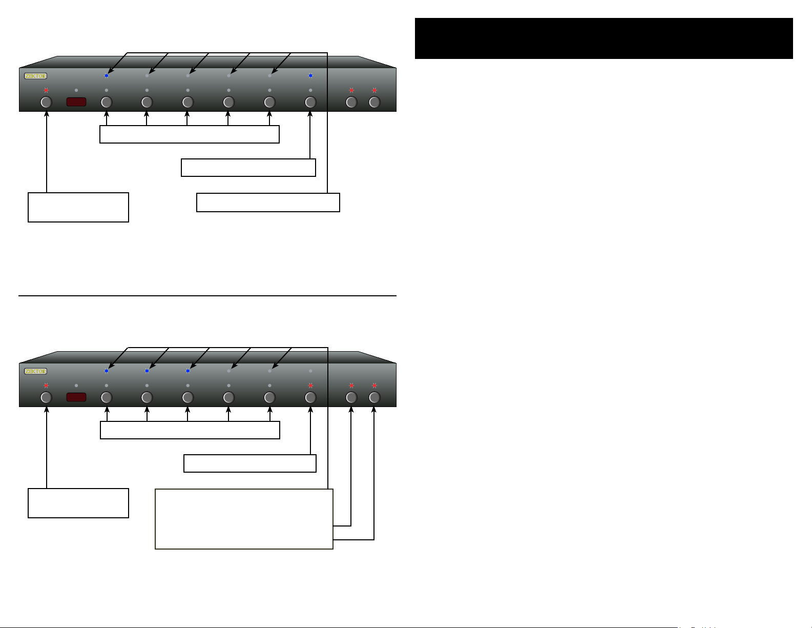
Step 3: Adjust Switching Delay Times
Changing Switching Delays
Th e H DV I5 al lo w s ad ju s ti ng t h e sw it c hi ng d e la y t im es , f or V id eo an d
Au d io , i nd e pe nd en t ly. By de fa ul t t he H D VI 5 us e s a 20 0 ms v id e o an d
au d io d el ay wh en sw it c hi ng b e tw ee n c ha nn el s. T h e HD MI sp ec if i ca t io ns c a ll s for a m i ni mu m o f 10 0m s , so m e mo ni t or s ma y r e qu ir e
mu c h la rg e r de la y t im e s to s w it ch re li ab l y.
To ad ju st th e Au d io /Vi de o s wi tc h in g de l ay s. . .
Step 1: Place the HDVI5 into the Setup Mode
Th e H DV I5 is p la c ed i nto t he se tu p m od e by pr e ss in g an d
•
ho l di ng t he Pow er bu tt o n fo r a bo ut 4 se co n ds .
Step 2: Enter the Switching Delay Setup Mode
Pre ss th e '5 ' b ut to n t o e nt er t h e Sw i tc hi ng De la y S et up
•
Mo de .
Th e b lu e L ED s in d ic at e t he V id e o mu te de la y , i f th e re a r e no
•
bl u e LE Ds l i t, t he n t he re is n o v id eo de la y .
Th e t ed LE Ds i n di ca te th e Aud io m u te d el a y, if th er e a re no
•
te d L ED s l it , th e n th er e i s n o au di o d el ay.
No LE Ds l it = 0 s ec d el a y.
• O ne l e ft j us ti f ie d LE D = 5 0m s de lay.
•• Two le ft j u st if ie d L ED s = 10 0m s d el ay.
•• • T h re e l ef t ju s ti fi ed LE Ds = 20 0m s d el ay.
•• • • Fou r le f t ju st if i ed L ED s = 3 00 m s de la y .
•• • •• Fi ve LE Ds = 5 00 ms d el a y.
• • •• Fou r r ig ht j u st if ie d L ED s = 1 s e c de la y.
• •• Thr e e ri gh t j us ti f ie d LE D s = 2 s ec d e la y.
•• Tw o r ig ht j u st if ie d L ED s = 3 s ec de la y .
• On e r ig ht ju st if i ed L ED = 4 s ec d el a y.
Toggle between audio
and video delays
Exit setup mode
Decrease delay
Increase delay
Step 3: Adjust Switching Delay Times
Th e ' SE L' b ut to n t og gl e s be tw e en t he V id e o de la y s et ti n g
•
an d t he A u di o de l ay s e tt in g.
Th e 'A 1 ' an d 'A 2 ' bu tt o ns a r e us ed to s e t th e de l ay t i me s
•
'A 1' de cr e as es t h e de la y t im e.
'A 2' in cr e as es t h e de la y t im e.
Pre ss th e Pow e r bu tt o n to sa ve ne w se t ti ng s a nd e xi t .
No t e: Th e ne w se t ti ng s ar e sa ved i n no n- vo l at il e me mo ry a nd
ar e n ot a ff ec te d by a po we r f ai lu re .
Page 14

24 HDVI5 Component Video Switch
25HDVI5 Component Video Switch
1 2 3 4 5 SEL A1 A2
Step 1: Place the HDVI5 into the Cable Length Tuning Mode
1 2 3 4 5 SEL A1 A2
Press and hold the desired channel until
the HDVI5 enters the cable length tuning
mode.
This example demonstrates entering the
cable length setup mode for input '5'.
Step 2: Adjust cable length settings
Toggle between cable length
and bandwidth settings.
(Blue = Length, Red = Bandwidth)
Decrease Cable Length
Input Cable Length Tuning
Th e H DV I5 fe at u re s r ec e iv er eq ua li z at io n t ha t ca n b e us e d to co mpe n sa te fo r t he l os s es t ha t o cc u r in v a ryi ng le ng th , a nd v a ryi ng
qu a li ty, c a bl es .
Th e H DV I5 al lo w s fo r 1 5 le v el s o f eq ua l iz at io n . Us i ng h ig h q ua li t y
DV I o r DV I t o HD M I co nve rs i on c ab l es , t he H DV I 5 ca n c om pe ns a te fo r
ca b le s of u p t o 6 5 fe e t (2 0 m et er s) , o n al l i ts i n pu ts a n d st il l r el i ab ly
re c ei ve a st a bl e, sp ar k l e fr e e im a ge a t 1 08 0p. L o ng er c a bl e le n gt hs
ca n b e ac he i ve d a t lo w er r e so lu ti o ns .
To tu ne a n H DV I5 ' s in pu t t o a s pe ci fi c c ab le le ng th . ..
Step 1: Place the HDVI5 into the Cable Length Adj. Mode
Pre ss th e de s ir ed i n pu t an d h ol d t he b ut t on f o r 4 se c on ds ,
•
un t il t he HD VI 5 e nt er s t he C a bl e Len gt h A dj . M od e.
Step 2: Enter the Cable Length Adj. Mode
Us e t he 'A1 ' a nd 'A2 ' b ut to n s to t u ne c ab l e le ng t h.
•
'A 1' ad ju st s f or sh or te r ca b le s.
'A 2' ad ju st s f or lo ng er ca bl es .
'S E L' sw it c he s to Ba nd w id th s et t in gs ( S ee n ex t pa g e) .
Sh o rt ca bl e s ar e i nd ic a te b y o nl y R ed L ED s b ei ng li t.
•
Me di u m le ng t h ca bl e s ar e i nd ic a te d by on ly Bl ue L E Ds l it .
•
Lo n g ca b le s ar e i nd ic a te d b y Bl ue & Re d L ED s be i ng l it .
•
Us e t he Po w er To g gl e b ut to n t o ex i t th e se t up m od e .
•
Wh e n a ca b le 's t u ni ng i s t oo s h or t, t he d i sp la y w il l b eg in t o s pa rk le ,
ev e nt ua l ly g oi n g bl an k . Fo r b es t re s ul ts , s ta r t l on g, an d u se a l e ng th
a s te p or tw o ab o ve an y n ot ic ea b le a rt if ac ts o n t he s c re en .
Tu ni ng a sh or t ca bl e t oo lo ng i nc r ea se s i ts s u sc ep ti b il it y to no is e,
ca u si ng p os s ib le d r op o u ts a nd sp ar kl es .
Increase Cable Length
Exit Setup Mode
No t e: Ou tp ut c ab le l en gt hs d ep en d on t he d is p la y' s re c ei ve r' s
ca pa bi l it ie s, a nd t he q ua l it y of c ab li ng u se d. Th e H DV I5
us e s so ur ce t e rm in at io n to c o mp en sa te f o r al l le ng th s of
ou t pu t ca bl es , an d to h el p i n ca se s wh er e th e re c ei ve r
ma y n ot h av e f ol lo w ed t he s pe ci fi c at io ns p ro pe rl y.
No t e: Ea ch i np ut c an b e tu ne d in di vi du a ll y an d al l se tt in gs a re
sa v ed i n n on -v ol at i le m em or y a nd a r e no t af fe c ted b y a
po w er f ai lu re.
Page 15
26 HDVI5 Component Video Switch
27HDVI5 Component Video Switch
1 2 3 4 5 SEL A1 A2
Step 1: Place the HDVI5 into the Cable Length Tuning Mode
1 2 3 4 5 SEL A1 A2
Press and hold the desired channel until
the HDVI5 enters the cable length tuning
mode.
Bandwidth & Sync Settings
Th e H DV I5 is a f u ll y di g it al s w it ch , u nl ik e m an y s im il a r pr o du ct s,
th e H DV I5 d e co de s t he D V I/ HD MI si gn al an d re -e nc od e s it o n t he
ou t pu t. T hi s a ll ow s i t to co rr e ct f o r ma ny no n- co m pl ia nt de vi ce s a tta c he d to it s in p ut s, an d al w ay s g en er a te f u ll y co m pl ia nt HD MI /D V I
da t a on i t s ou tp u t.
Th e f ol l ow in g p ar am e te rs ar e us u al ly b e st l ef t a lo ne a n d wi ll ha ve
no af fe c t on a f u ll y co m pl ia nt DV I/ HD M I so urc e, bu t ma y b e u se fu l
wh e n co nn e ct in g to a no n- co m pl ia nt so ur c e.
Ba nd wi dt h: Th i s se tt i ng a ll o ws t h e HD VI 5 t o sy n c to so ur c es w it h
cl o ck s th at ar e u ns ta b le a nd ar e ou t si de t h e DV I/ H DM I sp e ci fi ca ti o ns . T h e la r ge r th e b an dw i dt h, t h e be tt e r th e H DV I5 c a n to lo ck o n
to no n- st a nd ar d s ou rce s at th e ex p en se o f b ei ng mo re su sc e pt ib le
to no is e. So me P C c ar d s, a n d ol de r D VD p l ay e rs , m ay r e qu ir e t hi s
va l ue t o b e se t h ig h ( 6M Hz ) to wo rk re li ab l y.
Step 2: Adjust Bandwidth and Sync Settings
Toggle between Length &
Bandwidth Settings.
(Blue=Length, Red=B.W.)
HSync & VSync
(Red = Default)
HSJitter (Red=Default)
Bandwidth Settings:
3MHz = Red,Blue
4MHz = Red,Red (Default)
5MHz = Blue,Blue
6MHz = Blue,Red
Exit Setup Mode
HS Ji tt er : S om e no n -co m pl ia nt so ur c es c an ge ne rat e ho r iz on t al j it te r, c a us in g t he s cr e en t o j um p b ac k an d f or th h or i zo nt a ll y. En a bl in g
th i s se tt in g ( bl ue LE D is li t) w i ll e li m in at e t hi s p ro bl e m on a l l re s ol uti o ns w he re th e h or iz on t al p ixe l si z e is ev en ly di vi si b le b y f ou r.
HSy nc a nd VS y nc : W he n s et t o t he ir d e fa ul t v al ue s, th es e s et ti n gs
ha v e no ef fe c t on t he HS yn c a VS y nc s ig n al s. I f a so u rc e a nd m o ni to r
wi l l no t wor k wi t h ea ch ot he r, u si n g th e H DV I5 a n d en ab l in g on e o r
bo t h of t he s e se tt i ng s (b l ue L ED s a re li t) m a y fi x t he i n co mp at i bi li ty.
Step 1: Place the HDVI5 into the Cable Length Adj. Mode
Pre ss th e de s ir ed i n pu t an d h ol d t he b ut t on f o r 4 se c on ds ,
•
un t il t he HD VI 5 e nt er s t he C a bl e Len gt h A dj . M od e.
Step 2: Switch to the Bandwidth & Sync settings
Pre ss th e 'S E L' to t o gg le t o t he Ba nd wi dt h S et ti n gs m od e .
•
Us e ' 1' a n d '2 ' s et t he HD VI 5' s r ec e iv er ' s ba nd w id th .
•
3M H z = LE D ' 1' R ed & LE D '2 ' B lu e.
4M H z = LE D ' 1' R ed , L ED ' 2 ' Re d ( De fa ul t, HD MI S p ec ).
5M H z = LE D ' 1' B lu e , LE D ' 2' B lu e .
6M H z = LE D ' 1' B lu e , LE D ' 2' R ed .
Us e ' 3' t o s et H S Ji tt e r (R ED = De fa ul t, BLU E= En a bl ed ).
•
Us e ' 4' t o s et H S yn c ( RE D= De fa u lt , BLU E =S yn c a lw ays 0 ).
•
Us e ' 5' t o s et V Sy nc (R ED =D e fa ul t, BL U E= Sy n c al way s 0 ).
•
Page 16
28 HDVI5 Component Video Switch
29HDVI5 Component Video Switch
1 2 3 4 5 S EL A1 A2
Place the HDVI5 into the Setup Mode
1 2 3 4 5 SEL A1 A2
1 2 3 4 5 SEL A1 A2
Press and hold the Power Button until the
display goes wild. (About 4 seconds.)
Select Relay to Setup (A1 or A2)
Select a relay to setup by pressing either A1 or A2
Auxiliary Relay Options
Th e t wo g e ne ra l p ur po se au xi li a ry re l ay s a re ra te d a t 3 0 vo l ts A .C .
or D. C . @ 5 a mp s, an d ca n b e us e d to co nt r ol a nyt hi ng wi th in th os e
li m it s.
Th e re a r e 4 d if fe r en t o pe ra t in g mo d es o f t he R el a ys :
Mode 1 - Toggle
Th e r el a y to g gl es e a ch t im e t he r e la y 's b ut t on i s p re ss e d. T hi s i s th e
si m pl es t, a n d fa ct o ry de fa u lt , mo d e of o p er at i on .
Mode 2 - Momentary
Ea c h re l ay c a n be s et u p to st ay on a p r og ra m me d am o un t of ti me ,
an d t he n tu r n of f, e ac h t im e th e r el ay' s bu t to n is pr es s ed .
Mode 3 - Channel Controlled - Steady State
Th e r el a ys c a n be s e tu p to tu rn o n e ac h t im e sp e ci fi ed ch an ne l s ar e
se l ec te d. By s el e ct in g al l c ha nn el s , th e r el a y wi ll tu rn o n e ac h t im e
th e H DV I5 i s p owe r on , a nd t u rn o ff w h en t he HD VI 5 i s tu rn e d of f.
Mode 4 - Channel Controlled - Momentary
Th e r el a ys c a n be s e tu p to tu rn o n f or a pr o gr am m ed a mo u nt t im e
ea c h ti me s p ec if ie d c ha nn e ls a re se le c te d, a n d th en tu rn o f f.
Relay Setup Overview
If the red LED is lit, then the relay activates when
channel is selected. Use buttons to toggle LEDs.
The blue LED indicates Steady-State, the red LED
indicates Momentary. Use button to toggle LEDs.
Press Pwr Button to
exit setup mode.
Entering the Relay Setup Mode:
Place the HDVI5 into the Setup Mode
Pre ss an d ho l d th e P owe r to en te r S et up Mo de .
Select Relay to Setup (A1 or A2)
Ch o se t he re la y t o se t up b y p re s si ng A 1 o r A2 .
Relay Setup Overview
Se e i ll us tr a ti on fo r an ov e rvi ew o f t he R e la y Se t up M od e.
Th e fol low in g p age s d es cri be the se tti ng s f or eac h o f the di ffe re nt rel ay mo des .. .
The blue LEDs indicate delay times.
A1 = Decrease delay
A2 = Increase delay
Page 17
30 HDVI5 Component Video Switch
31HDVI5 Component Video Switch
1 2 3 4 5 SEL A1 A2
Toggle Mode
1 2 3 4 5 SEL A1 A2
Al l c ha nn el LE Ds a r e tu r ne d of f .
Relay Options (Cont'd)
Toggle and Momentary Relay Modes
If a ll ch an ne l L ED s a re o f f, th en th e re l ay w i ll n ot be a ffe ct ed by
ch a ng in g c ha nn el s . T h e 'S EL' bu tt o n is u s ed t o s wi tc h b et we e n th e
To g gl e Mo de an d th e M om en t ar y Mo de .
Press Pwr Button to
exit setup mode.
Momentary Mode
Al l c ha nn el LE Ds a r e tu r ne d of f .
Press Pwr Button to
exit setup mode.
Th e b lu e ' SE L' LE D i s li t .
De la y Ti m es a re ig n or ed .
Th e r ed 'S EL' L E D is l i t.
Blue LEDs indicate delay times.
A1 = Decrease delay
A2 = Increase delay
Toggle Mode
In t he Tog gl e M od e (t h e bl ue 'S EL' L ED is l it ) t he r e la y w il l t og gl e
be t we en O n a nd O ff e a ch t im e t he r e la y b ut to n i s pr e ss ed . A ll re la y
de l ay t im e s ar e i gn o re d i n th e To gg le Mo de .
Us e t he ' S EL' b ut t on t o s wi tc h t o t he To g gl e Mo d e (B lu e
•
'S E L' LE D li t ).
Momentary Mode
In t he Mo me nt a ry Mo de (t he r e d 'S E L' LE D is li t) t h e re l ay w i ll a cti v at e w he n it ' s bu tt o n is p r es se d , an d t he n t ur n it se l f of f a ft er a
pr o gr a mm ed a mo u nt o f t im e. Us e t he ' SE L' b ut to n t o s wi tc h t o th e
Mo me n ta ry M od e (t h e re d ' SE L' L ED i s l it ).
Us e t he 'A1 ' a nd 'A2 ' b ut to n s to a d ju st t h e am ou n t of t i me
•
th e r el ay is a c ti ve b efo re tu rn in g i ts el f o ff. T he d e la y ti m es
ar e i nd ic a te d b y th e t op r o w of bl ue L E Ds a nd co rr e sp on d
to th e fol lo w in g ti m es :
No LE Ds l it = Sa m e as Tog gl e M od e
• O ne l e ft j us ti f ie d LE D = 1 /4 s ec o nd s
•• Two le ft j u st if ie d L ED s = 1/ 2 se c on ds
•• • T h re e l ef t ju s ti fi ed LE Ds = 1 se co n ds
•• • • Fou r le f t ju st if i ed L ED s = 5 s e co nd s
•• • •• Fi ve LE Ds = 1 0 se co n ds
• • •• Fou r r ig ht j u st if ie d L ED s = 3 0 s ec on ds
• •• Thr e e ri gh t j us ti f ie d LE D s = 1 m in ut e
•• Tw o r ig ht j u st if ie d L ED s = 5 m in u te s
• On e r ig ht ju st if i ed L ED = 1 0 mi nu te s
Page 18
32 HDVI5 Component Video Switch
33HDVI5 Component Video Switch
1 2 3 4 5 SEL A1 A2
Channel Control - Steady State
1 2 3 4 5 SEL A1 A2
Re d L ED s in d ic at e i np ut s t ha t
ac ti vat e rel ay.
Relay Options (Cont'd)
Channel Control Modes
If a ny ch an n el L ED is l it , t he n t he r e la y w il l tu r n on w he n t ha t c ha nne l i s se le c te d du r in g no rm a l op er a ti on s . T h e 'S EL' bu tt on is u se d t o
sw i tc h be t we en t h e St e ad y St a te M od e , an d t he M om e nt ar y Mo de .
Press Pwr Button to
exit setup mode.
De la y t im e s in di ca t e ho w l on g
a r el ay ta ke s t o tu rn of f af te r
sw i tc hi ng aw ay fr o m an a c ti ve
in p ut .
Channel Control - Momentary
Re d L ED s in d ic at e i np ut s t ha t
ac ti vat e rel ay.
Press Pwr Button to
exit setup mode.
Delay times indicate how long a
relay stays on when switching to
an active input.
Bl u e 'S EL' L E D is l i t.
A1 = Decrease delay
A2 = Increase delay
Re d ' SE L' LE D i s li t .
Channel Control - Steady State
In t he St ea d y St at e M od e ( wh en b l ue ' SE L' L ED i s l it ) th e r el a y wi l l
re m ai n on fo r a s lo ng as t he HD VI 5 i s sw it c he d to an i np u t th at ha s
be e n se tu p t o ac ti va t e th e r el a y. W h en t he HD VI 5 i s sw it c h to an
no n -a ct iv e c ha nn el, t he re la y w il l t ur n of f a ft er t h e de la y t im e i nd ica t ed b y t he B l ue i np u t se le c ti on L ED s .
Us e t he ' S EL' b ut t on t o s wi tc h t o t he S te a dy S ta t e Mo de
•
(t h e bl ue ' S EL' L ED is l it ) .
Us e t he I np u t Se le ct b u tt on s t o ch o se w hi c h in pu ts wi ll
•
ac ti vat e th e r el a y.
Us e t he 'A1 ' a nd 'A2 ' b ut to n s to a d ju st t h e am ou n t of t i me
•
th e r el ay re m ai ns a c ti ve b efo re tu rn in g i ts el f o ff. T he d e la y
ti m es a re in di ca t ed b y t he t o p row o f b lu e LE D s an d c or re sp o nd t o t he d el a y ti m es g ive n on th e pr e vi ou s p ag e.
Channel Control - Momentary
In t he Mo me nt a ry Mo de (t he b l ue ' SE L' L ED l it ) t he re la y w il l t ur n on
fo r t he am ou nt of t im e i nd ic a te d b y th e B lu e in p ut s el e ct io n LE D s,
wh e ne ve r t he H D VI 5 is sw it ch e d to an i np u t th at ha s be e n se tu p t o
ac ti vat e th e r el a y.
Us e t he ' S EL' b ut t on t o s wi tc h t o t he M om en t ar y Mo de ( t he
•
re d ' SE L' L ED i s l it ).
Us e t he I np u t Se le ct b u tt on s t o ch o se w hi c h in pu ts wi ll
•
ac ti vat e th e r el a y.
Us e t he 'A1 ' a nd 'A2 ' b ut to n s to a d ju st t h e am ou n t of t i me
•
th e r el ay is a c ti ve b efo re tu rn in g i ts el f o ff. T he d e la y ti m es
ar e i nd ic a te d b y th e t op r o w of bl ue L E Ds a nd co rr e sp on d
to th e fol lo w in g ti m es . ( Se e th e p re vi o us p ag e f or re la y
ti m es .)
A1 = Decrease delay
A2 = Increase delay
Page 19
34 HDVI5 Component Video Switch
35HDVI5 Component Video Switch
Step 1: Reset All Parameters to Factory Defaults
1 2 3 4 5 SEL A1 A2
Resetting to Factory Defaults
If, f o r wh ate ve r r ea s on , yo u ’d li ke to r e se t you r HD V I5 b ac k t o it s f ac to r y d ef a ul t co n di ti on , t hi s i s ea si l y do ne. ..
Step 1: Reset All Parameters to Factory Defaults
Fir st pr es s a nd h ol d t he Po w er b u tt on
1.
Wh i le c o nt in ui n g to ho ld t h e Pow e r Bu tt o n, p res s an d h ol d
2.
bo t h th e ‘ 2’ an d ‘ 3’ bu tt o ns .
Af te r h ol di n g al l b ut to n s fo r a bo ut 4 se co n ds , t he d i sp la y
3.
wi l l fl as h i nd ic at i ng a ll pa ra m et er s h av e b ee n r es to r ed t o
th e ir f ac to r y p ro g ra m me d va l ue s.
1
Start by pressing and
holding the Power
button...
2
...while continuing to hold the Power
button, press and hold both the ‘2’
and the ‘3’ buttons.
3
After about 4 seconds, the display will flash
indicating all parameters have been restored
to their factory programmed values.
No t e: Re se ti ng th e HD VI 5 to i t s de fa ul t va lu e, re se ts e v er y-
th i ng t o th e sa me s ta te it w as w he n it l e ft th e fa c tor y!
Th i s in cl ud es a ny le ar ne d IR c o de s, a ll t im in g in fo r ma -
ti o n, c ab le l en gt h tu ni ng , e tc .
Pl e as e be a wa re of t hi s be fo re is su in g th is c om ma n d!
Page 20
36 HDVI5 Component Video Switch
37HDVI5 Component Video Switch
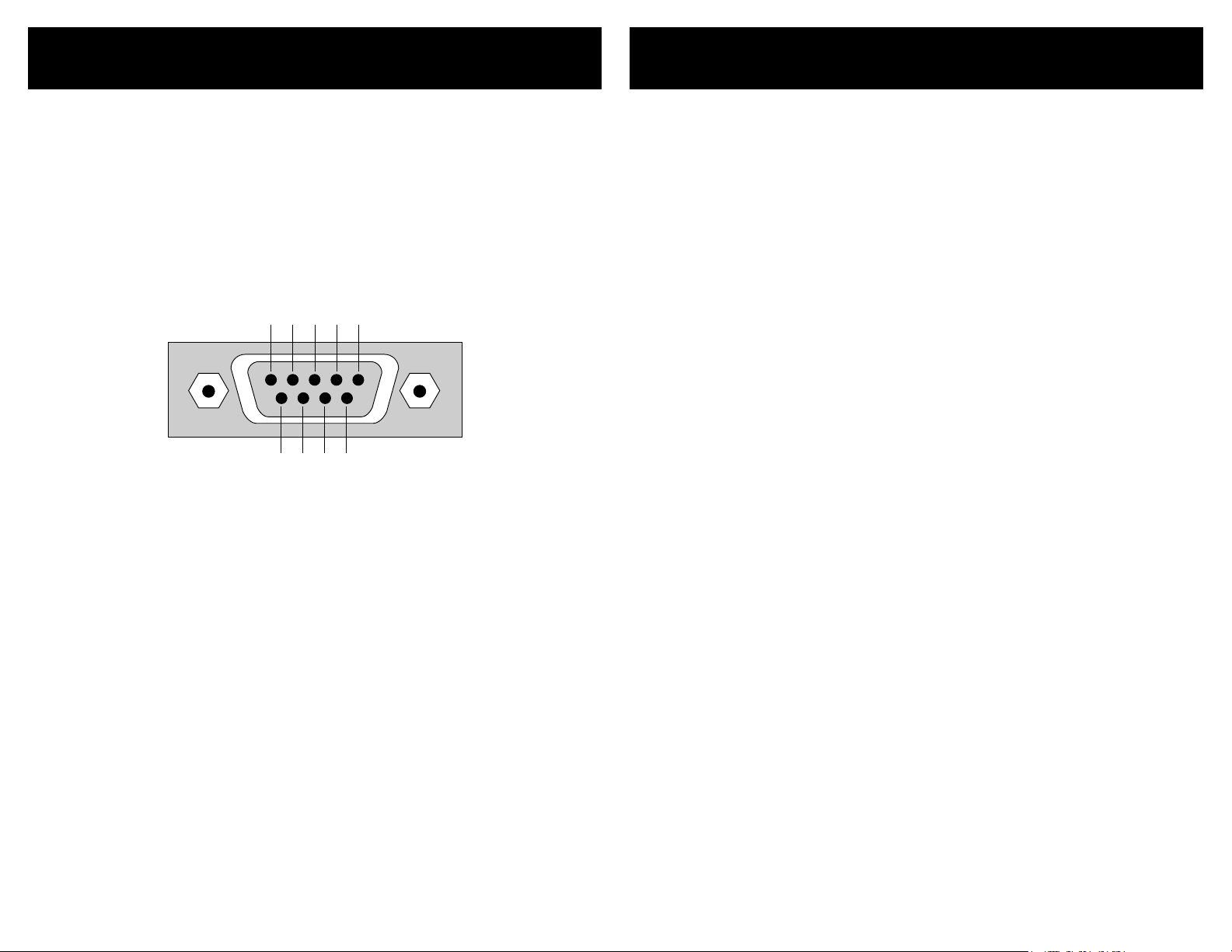
5 4 3 2 1
9 8 7 6
RS-232 Port
K.I.S.S.™ (Keep It Simple Serial!™)
Th e R S- 23 2 o n th e H DV I5 is t he sa me f o rm at as a P C -m od em , a nd
us e s th e sa m e ty pe c a bl e as a se ri a l mo de m w ou ld, w hi c h is a st an da r d st ra i gh t t hr ou g h ca bl e. Do n o t us e a c ab le th at i s m ar ke d a s a
“N u ll M od em” ca b le .
Th e H DV I5 ca n al s o be u s ed w it h a ny US B to RS -2 32 co nve rs io n
ca b le , th e se a re al l t yp ic al ly st ra i gh t th r ou gh ca bl es .
Th e R S- 23 2 p or t is a fe ma l e ty pe D E -9 c o nn ec to r ( so me ti m es m is t ak en l y re f er re d t o a s a DB -9 co nn ec to r ) wi th th e fol lo w in g pi n ou t:
Pin d ef i ni ti on s :
1 - N o Co nn e ct 6 - N o Co nn e c t
2 - T X 7 - N o C on ne ct
3 - R X 8 - N o C on ne ct
4 - N o Co nn e ct 9 - N o Co nn e c t
5 - G ND
Th e p or t se tt i ng s us e d by th e HD V I5 a re :
Ba u d r at e: 960 0
Da t a Bi ts : 8
St o p Bi ts : 1
Pa r i t y: NO N E
Th e c om m un ic at i on s pr o to co l u se d i s Ze k to r ’s ex c lu si ve K. I. S. S. ™
(K e ep I t Si mp l e Se ri al ™ ) pr o to co l .
Ze k to r ’s ex c lu si ve K. I. S. S .™ ( Ke ep It S im pl e S er ia l™ ) p ro t oc ol wa s de si g ne d by en gi n ee rs w h o ha v e be e n co nt r ol li n g RS -2 32 de vi ce s f o r
mo s t of t h ei r ca r ee rs a n d un de r st an d t he p it f al ls o f a b a dl y de s ig ne d
pr o to co l .
A few features of the K.I.S.S.™ protocol are:
A s im pl e an d l og i ca ll y c on si st e nt c o mm an d s tr uc tu re.
•
Fu ll y bi - dir e ct io na l o pe ra t io ns a n d ca n b e op er a te d i n bo th
•
a M as te r/ Sl a ve mo de ( o nl y re s po nd s w he n s po ke n t o) , or
in an A sy n ch ro n ou s mo d e (s ta t e ch a ng es a r e se nt as t he y
oc c ur ).
Al l c om ma n ds a nd re sp o ns es c a n op ti o na ll y u se a c h ec ks um
•
or a CR C- 8 c he ck co d e to in su re re l ia bl e c om mu ni c at io ns.
A c om ma nd wi ll a l wa ys ge ne ra t e a r es po n se ! T h er e a re n o
•
“t im e ou t” s ta t es a s p ar t of t he pr ot o co l. A ti m eo ut w i ll a lwa y s in d ic at e s om e t yp e of p h ys i ca l co n ne ct io n e rr or (l oo se
ca b le , ex tr e me n o is e, et c. ) .
Co m ma nd s a nd r e sp on se s h ave b ee n d es ig n ed f o r si mp l e
•
pa r si ng i n a ny la ng ua ge.
Ea s y to t e st u si n g a te r mi na l , or t e rm in al em ul at i on s of t-
•
wa r e. (H yp er te rm , S ec ur e CR T, e tc . )
A few features of the HDVI5 command set are:
A f ul l fe a tu re d c om m an d se t t ha t g oe s f ar b ey o nd s im p le
•
fr o nt p a ne l co n tr o l op er a ti on s! Al lo w s fu ll co nt r ol o v er a ll
fe a tu re s o f t he H DV I 5.
Al l f ro n t pa ne l f un ct io ns su pp or te d .
•
Fu ll n ot i fi ca ti o n of s t at e c ha ng es .
•
Th e a bi li t y to d i sa bl e t he f ro n t pa n el , a nd s ti l l ha ve fr o nt
•
pa n el b ut to n p re s se s se n t to th e se r ia l po r t.
Hi gh re so lu t io n co n tr o l ov e r al l t im in g s et ti ng s .
•
Th e a bi li t y to r e ad a l l IR c o de s se n t to th e HD V I5 b y a ny re -
•
mo t e, e v en t h os e no t u se d b y th e H DV I5 . U se t h e HD VI 5 t o
ad d I R co n tr ol to a n y pr o je ct !
Ma ny m ore f eat ur es, t oo nu me rou s to li st he re. ..
•
For a fu ll d e sc ri pt i on o f K .I. S. S .™ a nd a li st of t he co mm an d s su ppo r ted b y t he H D VI 5, d o wn lo a d th e HD V I5 s up p le me nt a l ma nu a l at :
ww w.z e kt or.c om /H D VI 5/ do w nl oa d s. ht m
Page 21
38 HDVI5 Component Video Switch
39HDVI5 Component Video Switch
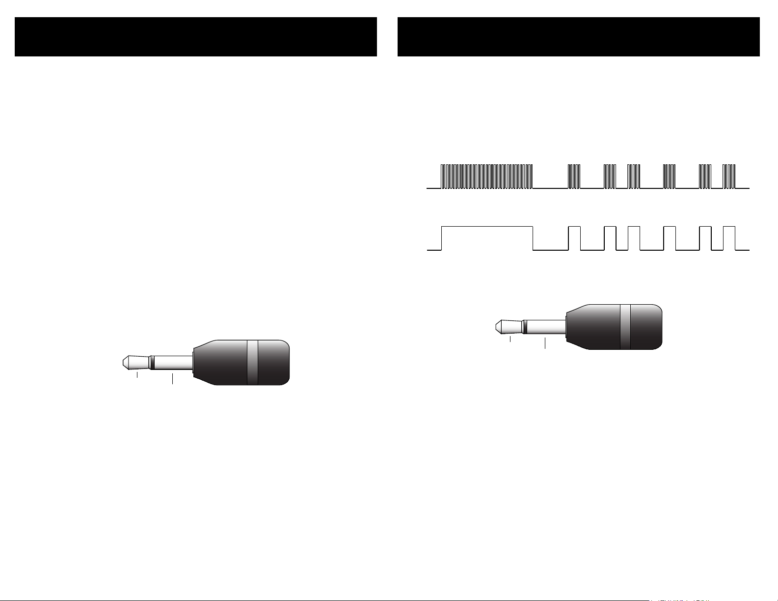
30KHz to 500KHz
+3V to +15V
0V
MODULATED SIGNAL
UNMODULATED SIGNAL
+3V to +15V
0V
GND
SIGNAL
+3V to +15V
+12V On / Off Control
GND
On/Off Voltage:
High = +3V to +15V
Low = Below 0.2V
Rear Panel IR Control
Th e r ea r p an el ja ck l a be le d " IR /Z- IN " a ll ow s t he H D VI 5 to be t u rn ed
on an d of f u si ng a +1 2V c o nt ro l v o lt ag e.
To en ab le / di sa bl e t he + 1 2V O n/ O ff co n tr o l fu nc ti o ns , s ee t he se ct io n
en t it le d: "C on tro l Fu nct io ns" .
By e n ab li ng th e +1 2 V On /O ff c o nt ro l o pt i on , th e H DV I5 wi ll t u rn
it s el f on w h en ev e r th e v ol ta g e go in g i nt o t he Z- IN ja ck g o es f rom
LO W to HI GH , a nd i t w il l tu r n it se lf of f wh e ne ve r t he vo lt ag e g oe s
fr o m HI GH to LO W.
Th e H DV I5 on ly l o ok s at tr an s it io ns on t he Z- I N ja ck . F or in st an c e
if it d et e ct s a LO W to HI GH t r an si ti o n it w i ll t ur n i ts el f o n. T he u s er
ca n t he n us e t he p o we r s wi tc h t o t ur n of f t he H DV I 5. A f te r wh ic h t he
vo l ta ge o n t he Z- IN ja ck m u st g o f ro m H IG H to LOW a n d th en ba ck t o
HI G H, t o o nc e ag a in t ur n o n th e H DV I5 .
Th e H IG H l ev el is a ny vo l ta ge a b ov e + 3V u p t o +1 5 V.
Th e LO W l ev el i s a ny vo lt a ge b el o w 0. 2 V.
An y v o lt ag e b et we en th es e t wo l ev e ls i s u nd ef in e d.
Th e r ea r p an el ja ck l a be le d " IR /Z- IN " a ll ow s t he H D VI 5 to be c o ntr o ll ed b y h ar d wi re d I R co n tr o ll er s.
To en ab le / di sa bl e t he r e ar p a ne l IR j a ck , se e t he s ec ti o n en ti t le d:
"C on tr ol Fu nc tio ns ".
Th e I R si g na l c an b e ei t he r mo d ul at e d or u n mo du la t ed :
An d u se s a s ta nd ard 1 /8 " ( 3. 5m m ) mi ni - pl ug :
No t e: Th e + 12 V On /O ff c on tr o l op ti on i s mu tu al ly e x cl us iv e
wi t h IR C on t ro l ja ck o pt io n, o nl y on e o f th e op ti on s ca n
be en ab le d at a t im e.
Th e s ig n al v o lt ag e c an r a ng e fr o m +3 V t o +1 5V.
Th e s ig n al c an be e it h er u nm o du la te d , or mo du la t ed w i th a m o du la ti o n fr e qu en c y r an g in g f ro m 30 K Hz t o 5 00 KH z.
Th e I R ja c k re c og ni z es t h e sa me IR c od e s as t h e fr o nt p an e l IR s e nso r. I f th e H DV I5 is t au g ht n ew co de s , th e se n ew c o de s w il l be c om e
th e n ew c o de s re c og n iz ed by t he IR j ac k .
No t e: Th e I R co nt rol j ac k op ti on i s mu t ua ll y exc lu si ve wi th
+1 2 V On /O ff co n tr ol o pt io n, on ly o ne o f th e op ti on s ca n
be en ab le d at a t im e.
Page 22
40 HDVI5 Component Video Switch
41HDVI5 Component Video Switch
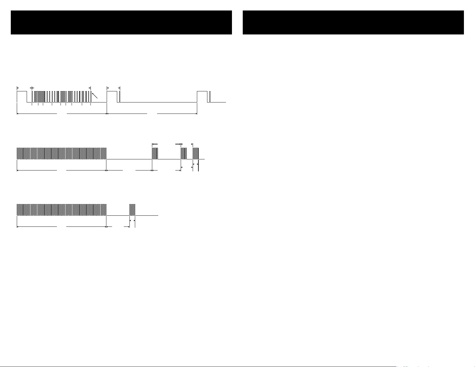
IR Code Format
108 mS 108 mS
8 0 7 D 0 8 F 7
Stop Bit
Leader Data Bits
Repeat Code
9 mS 4.5 mS 2.25 mS
1 Bit 0 Bit
1.125 mS
0.56 mS
9 mS 2.25 mS
0.56 mS
IR Codes
Th e d ef au l t IR c o de s us e d by th e HD V I5 a re 32 b i ts l on g , ba s ed o n
th e N EC t ra n sm is s io n pr o to co l a nd u s e a ca r ri er f req ue nc y of 38 KH z.
Ty pi ca l I R Co d e. E x am pl e C od e = 8 0 7 D 0 8 F 7 ( he x) :
A m ag ni fi e d vi ew of t he Le ad e r an d f ir st t h re e d at a bi t s:
A ma gn if i ed v ie w o f th e R ep ea t C od e ( se nt wh en k e y is h e ld d ow n ):
.
Th e f ol l ow in g a re th e fa c to ry de f au lt c o de s us e d by th e HD V I5 :
Ha n dh el d
Re m ot e Co de s Fu nc tio n
8 0 7 D 0 0 F F Pow e r Tog gl e
8 0 7 D 0 8 F 7 '1 ' B ut to n
8 0 7 D 2 8 D 7 ' 2' B u tt on
8 0 7 D 1 8 E 7 ' 3' B u tt on
8 0 7 D 3 8 C 7 ' 4' B u tt on
8 0 7 D 8 0 7 F ' 5' B u tt on
8 0 7 D A 0 5 F ' SE L' B ut to n
8 0 7 D 9 0 6 F 'A 1 ' Bu tt o n
8 0 7 D B 0 4 F 'A 2 ' Bu tt o n
Di sc re t e Co d es F u nc tio n
8 0 7 D 0 4 F B Di sc r et e P owe r On
8 0 7 D 1 4 E B Di sc r et e P owe r Of f
8 0 7 D C 4 3 B S eq ue nc e Th r ou gh In pu ts
8 0 7 D 2 4 D B N o Br e ak aw ay
8 0 7 D 3 4 C B A ud i o Br e ak aw ay
8 0 7 D 4 4 B B V id e o Br e ak aw ay
8 0 7 D 5 4 A B D is cr e te R e la y 1 O n
8 0 7 D 6 4 9 B D is cr e te R e la y 1 O ff
8 0 7 D 7 4 8 B D is cr e te R e la y 2 O n
8 0 7 D 8 4 7 B D is cr e te R e la y 2 O ff
Th e se a re th e d ef au lt co de s o f th e H DV I5 , t he y ca n b e ea s il y
ch a ng ed b y t ea c hi ng t he HD VI 5 a n ew s e t of I R c od es -- u se f ul i f
mo r e th an on e HD V I5 r e si de s i n th e s am e ro o m.
To ch an ge IR c o de s, se e th e s ec ti on s : "U si n g a Di f fe re n t Re m ot e" an d
"L e ar ni ng Ne w Di s cr et e I R C od es ".
Page 23

42 HDVI5 Component Video Switch
43HDVI5 Component Video Switch
Features
Specifications
Features of the HDVI5:
Tru e d i g it al s w i t ch in g. By f ul l y de c od in g t he D V I / H DM I s i g na ls
•
an d r e- c re at i n g t he m o n th e o ut pu t , th e H DV I5 al wa y s ou t p u ts
fu l ly c o mp li a n t D VI /H D MI s ig n al s, re ga r dl es s o f th e q ua l i t y of t h e
si g na ls be in g r ec ei ve d .
Tun ab l e ca bl e l e n gt hs . T he H D V I i nc or p o r at es u s er a dj u st ab l e
•
eq u al iz a ti on o n a ll o f i t' s i np ut s , al l ow in g t he u s er t o t un e th e
HD V I5 t o t he l e ng th a n d qu al i ty o f c ab l e us ed on e a ch i n p u t fo r
th e a bs o lu te b e st p os s ib le m a tc h. A ll ow i ng c a bl e l e n gt hs o f 6 5f t t o
be us ed fo r s p a rk le f r ee 1 08 0 p re c ep ti o n. E ve n l on g er l e n g th s ar e
ac h ie va b le a t l ow er r e so lu ti o ns . M an y o th er a d ju st m en ts a r e al so
av a il ab l e to h e lp c le a n up p o or s i gn al s .
Un m at ch e d co n t r ol f ea t ur es . T he H DV I 5 ca n b e co n tr ol l e d u si ng
•
fr o nt p a ne l b u t to ns , a n IR r e mo te , a h a rd wi re d I R r em ot e j ac k,
RS - 23 2, an d e v e n a si m pl e +1 2 V On / Of f v ol ta g e . I t ca n b e ta ug h t
to us e a d iff er en t r e mo te co nt r o l , al lo w in g yo u t o h av e a n un li m it e d nu m be r o f HD VI 5' s i n th e s am e r oo m a nd s t il l c on tr o l th em a l l
se p ar at e ly. T h e R S- 23 2 c om ma n d se t i s o n e o f th e e as ie s t to us e
on th e m ar ke t a nd a ll o ws u np r ec ed e nt ed co nt ro l o ve r t he H D VI 5' s
op e ra ti o ns .
A se pa ra t e Di g it al A ud io s w it ch . R eq ui r ed b y t ru e D VI , bu t i n ma n y
•
ca s es i t 's s i m p ly m or e c on ve n ie nt to r o ut e th e d ig i ta l a u d io o ut si d e th e d ig i t a l vi de o p at h. Th e HD V I 5 f ul l y su p po rt s H DM I au d io
th a t is se nt a s p ar t a s of t h e HD M I si g na ls , b ut i t a ls o f ea tu re s a
fu l ly s e pa ra t e Di gi ta l Au di o s wi t ch , wi t h au d io b r e a ka wa y, th at ca n
be us ed to r o u t e di gi t al a ud i o si g na ls ou ts id e o f t he H D M I s ig na l s.
Th i s al l ow s t h e a ud io to b e r ou te d t o a h om e t he at e r re c e i ve r an d
th e v id e o to b e s en t t o th e m on it o r. ( No te : T he H D VI 5 d oe s n o t
br e ak o u t th e H DM I au d io f ro m t he HD MI vi de o. )
Ad j us ta b le f r o n t pa ne l L ED i n te ns i ti es . E li mi n at e t he d i s t ra ct io n o f
•
gl a ri ng LE Ds b y h av in g t he f r on t p an el di m af t er a fe w s e c on ds o f
si t ti ng id le . T he LE D s ca n e ve n b e di mm e d to " o ff " .
Au x il ia r y Re l a y s. Two d r y co n ta ct (l ow v o lt ag e ) re l a y s ar e a va il -
•
ab l e to co nt r o l w ha te v er m ig h t ne e d co n tr ol li n g. P ro je c t i on
sc r ee ns , o r r a c k li gh t in g, w h at ev e r. E ac h re l ay c a n be c on t ro ll ed
us i ng I R , RS - 2 3 2, o r f ro nt p a ne l b ut to n s. S et u p th e r el a y s t o tu r n
on wh en sp ec i f i c in pu t s ar e s el ec t ed , o r wh en th e H DV I5 i s t ur ne d
on , o r h av e t h e m op er a te f ul l y in d ep en d en t of th e H DV I5 .
Pe r fe ct fo r t h e p ro fe s si on al ho me th ea t er i ns t al le r ! T he H DV I 5 i s
•
ra c k mo u nt ab l e an d co m es i n b la ck or s i lv er. Wi th m o re c on t ro l
fe a tu re s t ha n a ny o th e r DV I/ H DM I s wi tc h o n th e m ar k et , a n d l oo ks
th a t wi l l ma t c h a ny p r oj ec t, th e H DV I5 is y ou r c us t om er ' s id ea l
so l ut io n !
Specifications:
Digital Video Channels
Protocols:
DVI / HDMI Bandwidth:
HDTV Resolutions:
HDCP:
HDMI Audio:
PC Resolutions:
Digital Audio Channels
Inputs:
Outputs:
Maximum Transfer Rate:
Digital Audio Modes:
Coax Input Level Range:
Coax Output Level:
Control
IR Sensor:
IR Jack:
+12V Control:
Relay Contacts:
Serial Port:
Power Requirements:
Voltage Reqirements:
Optional International:
Adapter Power Supply:
Dimensions:
Warranty:
DVI 1.0, HDMI 1.0 through HDMI 1.2a
(HDMI 1.3 as of 5-10-2006)
1.65GHz
480p through 1080p, including 720p and 1080i
(All Single Link DVI / HDMI modes are supported)
Both DVI and HDMI HDCP modes are supported
Fully supports all HDMI Audio modes
640x480p through 1920x1200p
(All Single Link PC resolutions supported)
5 Coax, 5 Optical, (Auto conversion between formats)
1 Coax, 1 Optical, (Simultaneous)
Optical 13.2Mb/S, Coax 50Mb/S
PCM, DD5.1, DTS, All digital audio modes supported
200mV - 7.0V (PC Soundcard Compatible)
500mV Nominal
Modulation Frequency: 34KHz-42KHz
+3V to +15V, Un-Mod. or 30KHz to 500KHz Mod. Freq.
+3V to +15V for ON, less than 0.2V for OFF
Contacts rated at 30 Volts A.C. or D.C. @ 5 Amps
9600 Baud (8N1), USB Serial Cable Compatible
K.I.S.S.™ Protocol, Firmware Upgradeable
1W Standby, 6W Nominal, 12.5W Worst Case
90-120VAC, 60Hz
90-264VAC, 47-63Hz
Wall Mount, 9V @ 1200ma, U.L. Listed
Rack Mountable, 17”W x 6.5”D x 1.75”H
Two Year Parts and Labor
Page 24

44 HDVI5 Component Video Switch
45HDVI5 Component Video Switch
Warranty Policy
Contact Information
Warranty Policy
ZE K TO R wa r ra nt s t hi s p ro du ct a g ai ns t d ef ec ts i n m at e ri al a n d wo r kma n sh ip u nd e r no rm a l us e a nd s er vi ce fo r t wo y e ar s fro m th e o ri gi na l d at e o f pu r ch as e. ZE KT O R, a t i ts o p ti on , s ha ll r e pa ir o r r ep l ac e
th e d ef e ct iv e u ni t co v er e d by th is w a rr an t y.
In o rde r to ke ep t h is w a rr an ty i n e ff e ct , th e p ro du c t mu st h a ve be en
ha n dl ed a nd us ed a s p re s cr ib ed in t he in st ru c ti on s ac c om pa n yi ng
th i s wa rr a nt y. T h is w a rr an ty d o es n ot co ver a ny da ma g e du e t o ac c ide n t, m is u se , a bu se , o r ne g li ge nc e . T h is w a rr an t y is v al i d on ly if t he
pr o du ct i s u se d as sp ec if i ed i n t he p ro d uc t do cu m en ta t io n.
Re pa i r or r e pl ac e me nt , a s pr o vi de d u nd er th is w a rr an t y, is y o ur
ex c lu si v e re m ed y. Z EK TO R s ha ll no t be li ab le fo r a ny i n ci de nt a l or
co n se qu en t ia l da m ag es . I mp li ed wa rr an t ie s of me rc h an ta bi l it y an d
fi t ne ss f o r a p ar ti cu la r pu r po se o n t hi s p ro du c t a r e li mi t ed i n d ur ati o n to t h e du ra t io n o f th is wa rr an t y.
So me st at e s/ co u nt ri es do n ot a l lo w t he e xcl us io n o r li m it at io n o f
in c id en ta l o r co n se qu e nt ia l d am ag es , s o t he a bo v e li m it at i on o r
ex c lu si o n ma y n ot a p pl y to yo u. So me s t at es / co un t ri es d o n ot a llo w l im it a ti on s o n ho w l on g a n im pl i ed w ar r an ty l as t s, s o t he a b ov e
li m it at io n m ay no t ap p ly t o y ou . Th is wa rr an t y gi ves y o u sp ec i fi c
le g al r ig ht s , an d y ou ma y al s o ha v e ot h er r ig ht s t ha t v ar y fr o m st ate
to st at e a nd c o un tr y to co un t ry.
Return & Exchange
Sh i pm en t o f pr o du ct i s a s ad ve r ti se d by pr od u ct . Up on re ce i pt o f
me r ch an di s e in sp e ct p ro d uc t ca re f ul ly, sh ou ld yo u f in d th a t th e
pr o du ct d oe s n ot m e et y o ur e xp e ct at io ns, o r s at is fa c ti on , co n ta ct
us at o nc e a nd t e ll u s y ou r c on ce r ns , so we m a y ma k e ev e ry ef for t to
sa t is fy y o ur p u rc ha se.
Instructions for Returning Items
Pl e as e re t ai n t he d at e d sa le s r ec e ip t as ev id en c e of t h e da t e of
pu r ch as e. Yo u wi ll ne ed i t f or an y w ar ra n ty s er vi ce . I f yo u b ou g ht
th e p ro d uc t th ro u gh a d e al er, in st a ll er, or r e se ll er, yo u w il l n ee d t o
re t ur n th e p ro d uc t to th e po i nt o f s al e.
E- m ai l or c a ll u s, us in g t he i n fo rm a ti on l i st ed u n de r “ Cus to m er S er vi c e Co n ta ct I nf o rm at i on ”, f or a Re tu rn t o M an uf a ct ur er Au th or i za ti o n (R MA) n um b er. De sc ri be br ie fl y t he r e as on s f or yo ur r e qu es t ed
re t ur n.
Yo u m us t r ec e iv e an RM A # b ef o re y o u re t ur n any g oo d s to us . Th e
RM A # m us t a pp ea r o n yo u r re t ur n pa c ki ng l ab e l or o n t he o u ts id e
of th e bo x . Me rc h an di s e wi th o ut a n R MA # w i ll b e r ef us e d. R M A’s ar e
va l id f o r tw e nt y (2 0) da ys fr om da te of i ss u an ce .
Al l r et ur n ed m er c ha nd i se m us t b e sh i pp ed i n t he o r ig in al pa ck ag in g .
If i t i s no t i n th e o ri gi na l p ac ka gi n g, Z E KTOR w i ll n ot b e h el d l ia bl e
fo r d am a ge d ur in g s hi pm e nt . Sh i pm en t s of r e tu rn s m us t be pr ep a id ,
an d w e wi l l no t a cc ep t C O D re t ur ns .
Customer Service Contact Information:
Zektor
12675 Danielson Ct.
Suite 401
Poway, CA 92064
Phone: 858-748-8250
Fax: 858-748-8224
E-mail: customerservice@zektor.com
Website: www.zektor.com
Page 25

Z E K T O R
Z E K T O R
12675 Danielson Ct
Suite 401
Poway, CA 92064
858•748•8250
www.zektor.com
 Loading...