

Page 1

Z E K T O R
1 2 3 4
ZE KT OR
Home Theater Switches
Digital Video / Component Video / Multichannel Audio
HDS4.1
High Definition Component Video Switch
Rev 2 02/22/2006
Page 2

ii HDS4.1 Component Video Switch
1HDS4.1 Component Video Switch
Contents
What’s Inside
Tha n k y o u f o r y o ur pu rc h a se of y o u r H DS 4 .1 H ig h D e fi n it io n C o m po nen t V i d eo Sw i t ch .
What ’s Inside ..................................... 1
An Over view of the HDS4.1 ................ 3
Easy, Simple, Instructions! ................. 5
Thre e Simple Steps to a Remote! ........ 7
Controlling the Front Panel Lights ..... 9
Adjusting the Front Panel Intensity .. 11
Setting the Initial Power On State .... 13
Disabling Front Panel or Remote ...... 15
Resetting to Factory Defaults ........... 17
Specifications .................................. 19
Warranty Policy ............................... 20
Contact Information ........................ 21
Ever y c ar e h a s b ee n t a ke n t o a ss u re y ou of a s uc c es s fu l i n st a ll at i o n
and s ub se q ue n t o pe r at i on s o f y o ur ne w H D S4 . 1 vi d eo sw i tc h , h ow e v e r
sho u l d so m et h in g g o w ro n g , a n d w ar ra n t y re p ai r w o r k is ne e de d , w e
req u e st th a t y o u ho l d o n t o t he or ig i n al p a ck ag i ng ma t er i al s .
Ple a s e t ak e t hi s t i me to ve r if y t h e c on t e nt s o f t he HD S 4. 1 b ox .
The f o ll o wi n g s ho u ld b e i n cl u de d :
HDS 4 . 1
1.
Power S up p ly Mo du l e
2.
Thi s Us e r’s M an u al
3.
If a ny t h in g i s m is s in g p le a se ge t i n t o uc h w i th u s a s s o on as p o ss i bl e
so t h at we ca n c o rr e ct t h e s it u at i on .
Page 3
2 HDS4.1 Component Video Switch
3HDS4.1 Component Video Switch
1 2 3 4
ZE KT OR
R/V L/H C/V
Y/G Pb/B Pr/R
R/V L/H C/V
Y/G Pb/B Pr/R
R/V L/H C/V
Y/G Pb/B Pr/R
R/V L/H C/V
Y/G Pb/B Pr/R
R/V L/H C/V
Y/G Pb/B Pr/R
DIGITAL AUDIO
1 2 3 4 OUT
4 OUT OUT
1 2 3
9VDC
1 2 3 4 OUT
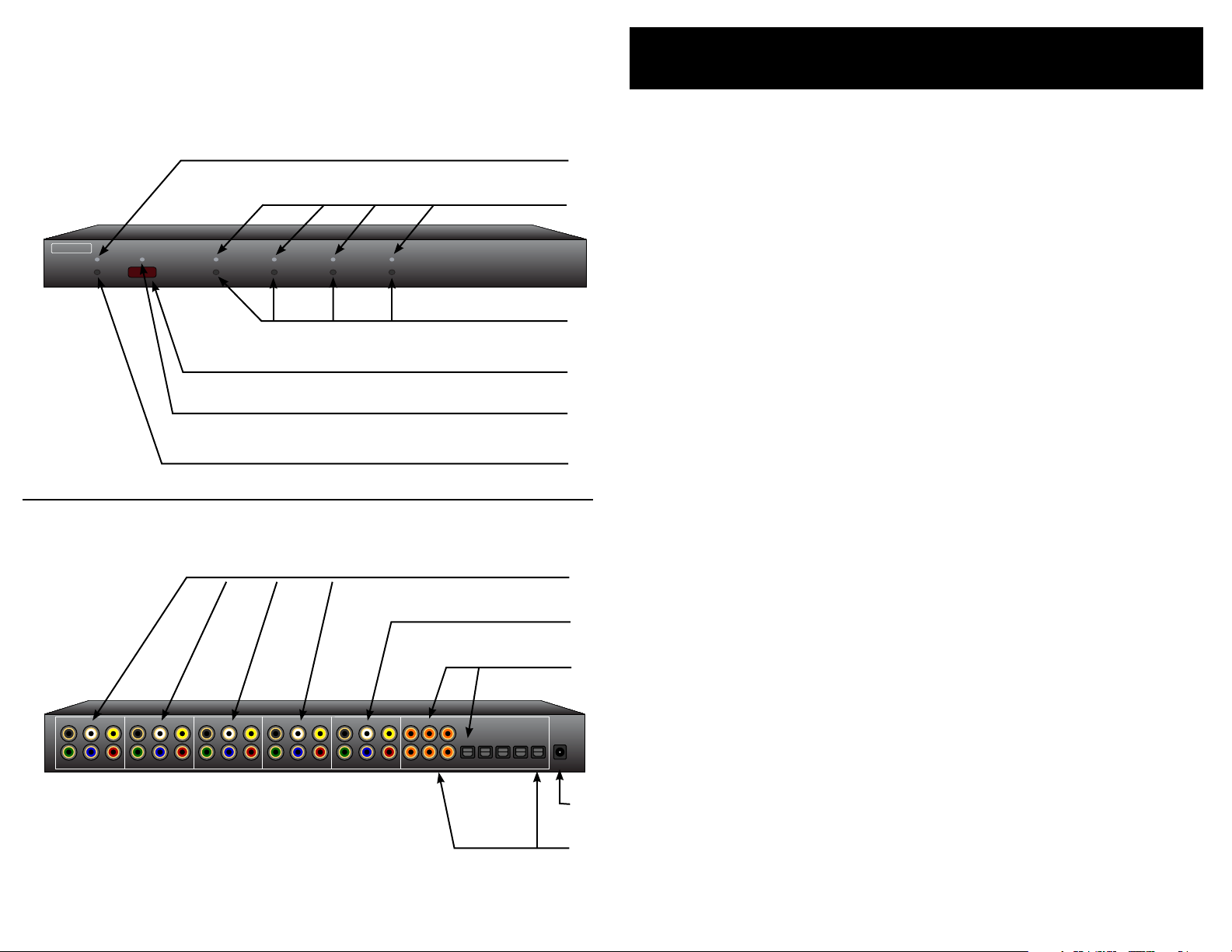
An Overview of the HDS4.1
Front Panel
Rear Panel
Front Panel Controls:
Power I nd i ca t or. L i gh t s u p i n s ta n db y m o de .
1.
1
2
Se l e ct io n L E Ds . I nd i ca t e c u rr e nt l y s el ec te d in pu t s.
2.
In p u t S el ec ti o n B ut to n s .
3.
In f r ar e d R em o te Se n so r Win d o w.
4.
In f r ar e d R ec e iv e d I nd i ca t or. Fl a s he s w h en I R i s r e ce i v ed .
5.
Power To g gl e B u tt o n.
6.
3
4
5
6
Rear Panel Connections:
Ana l o g In p ut s. Ea c h in p ut co n si s ts of si x e qu i va l en t c h an -
1.
nel s . The c ha n ne l s a re co l or e d a n d l ab el e d f o r c on v e ni e nc e ,
1
2
3
4
5
howe v e r a ll si x c h an ne l s a re o f eq u iv a le n t b an d wi d th an d
fun c ti on a li t y, a n d m ay be in t er c h an g ed as d e si r e d.
Ana l o g Ou t pu t s.
2.
Dig i t al Au d io In pu t s. E ac h i np u t h as an as so c ia t e d di g i ta l
3.
aud i o c ha n ne l w i th bo th a C o ax an d a n O pt i ca l c o nn e ct io n.
Onl y on e o f t he tw o t yp e s o f in p ut s c a n b e ac ti v e a t a n y
tim e . The H DS 4 .1 wi l l a ut o -s el ec t b et we e n t h e t wo t y pe s o f
sig n a ls . If a s i gn a l i s s up p li e d t o b ot h t he Co a x a n d Op t ic a l
inp u t s, th e C o ax si g n al i s g i ve n pr io r it y.
DC P o w e r J ac k C o n ne ct o r. Pl u g i n t he su p pl i ed p o w er
4.
ada p t er in t o t hi s j a ck .
Dig i t al Au d io Ou t pu t s. Al l d i gi t al au d io in pu t s a re a ut o ma t -
5.
ica l l y co n v e rt ed to bo t h Co a x a n d O pt ic a l o ut p ut s . A ll th r ee
out p u ts a r e a v ai l ab l e a t a ll ti m es , a n d a re al l i n di v id u al ly
buf f e re d to al l ow dr i vi n g th r e e d if f er e n t d ig i ta l a u di o d evic e s s i mu l ta ne o us l y.
Page 4
4 HDS4.1 Component Video Switch
5HDS4.1 Component Video Switch
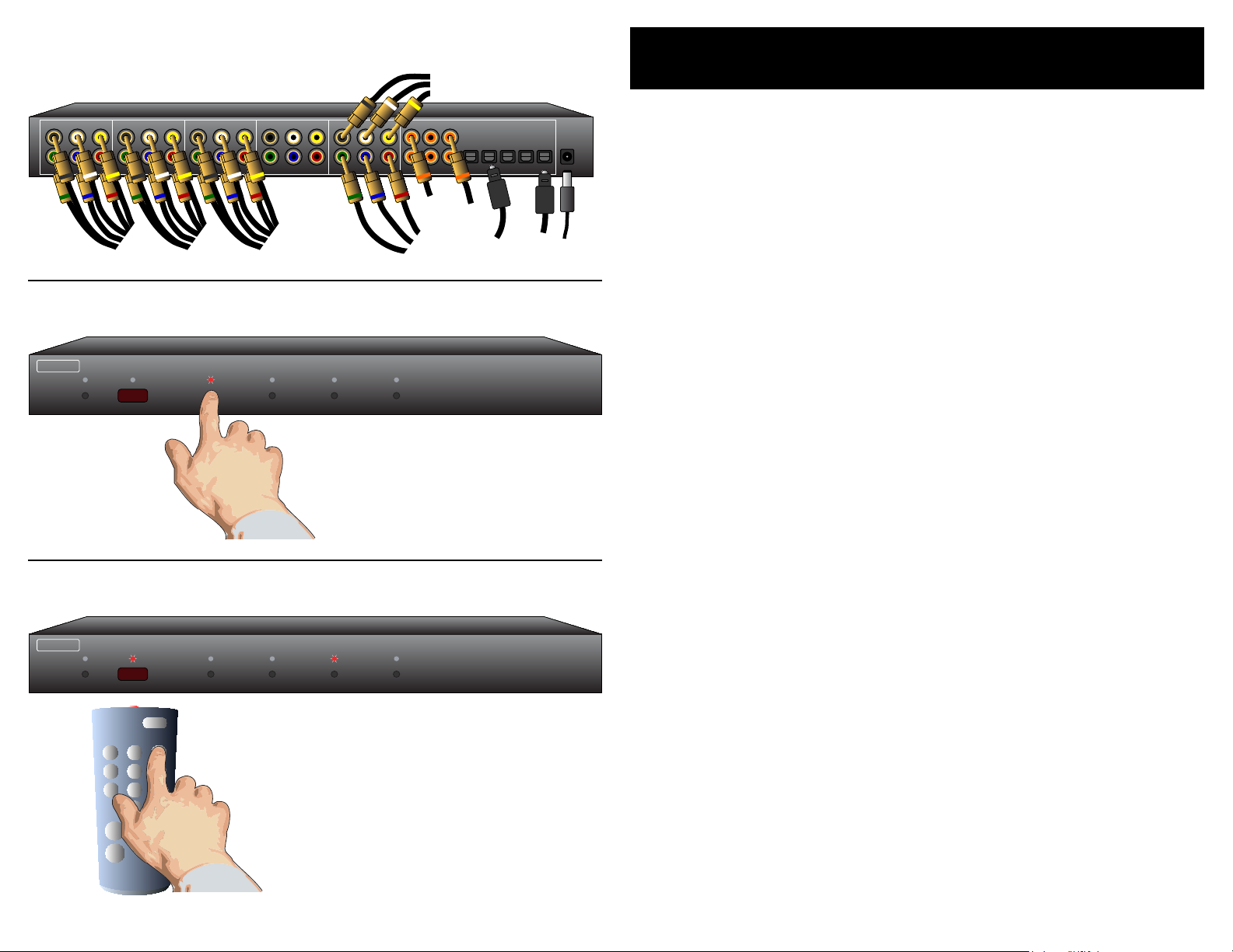
Step 1: Make the appropriate connections.
R/V L/H C/V
Y/G Pb/B Pr/R
R/V L/H C/V
Y/G Pb/B Pr/R
R/V L/H C/V
Y/G Pb/B Pr/R
R/V L/H C/V
Y/G Pb/B Pr/R
R/V L/H C/V
Y/G Pb/B Pr/R
DIGITAL AUDIO
1 2 3 4 OUT
4 OUT OUT
1 2 3
9VDC
1 2 3 4 OUT
To
Cable
Box
To
Cable Box
Digital Audio
To
DVD
To
Game
Console
To Game
Console
Digital Audio
Unused
Input
To
Projector
or
Monitor
To Power
Module
To
Composite
Monitor
w/Analog
Audio
To Home Theater
Receiver’s Digital
Audio Input
To DVD
Digital Audio
1 2 3 4
ZE K T O R
1 2 3 4
ZE KT O R
1 2 3
4 5 6
7 8 9
0
+ +
_ _
POWER
VOL
CH
Step 1...
•
•
Easy, Simple, Instructions!
Use t he an a lo g i np u t c on n ec ti o ns to sw i tc h c o mp o ne n t
vid e o / c o m po si t e v id e o / a n al o g au d io or an y co m bi n at i on
of t h e ab o v e s ig n al s t o t h e H DS 4 .1 ’s a n al o g o ut p ut co n ne c tor s . Us e t h e d ig i ta l a ud i o c on n ec to r s t o s wi t c h di g i ta l a udio s ig n al s , w it h f u ll fo r ma t c o nve r s io n b et we e n t h e o pt ic a l
and c oa x d i gi t al au di o f o r ma t s.
Plu g th e p o we r m o du l e i nt o t h e H DS 4 .1 , a nd pl u g t he mo d ule i nt o a st a nd ar d A. C . w al l r e ce p ta c le . T h e s t an d by LE D
wil l li gh t u p .
Step 2: Press buttons to select an input.
Step 3: Or use nearly ANY remote to select an input.
Turn to the next chapter for simple instructions
on how to setup the HDS4.1 for use with
any existing remote!
Step 2...
To s wi tc h be tw e en an y of th e f o ur in p ut s , s im p ly pr e ss
•
the b ut to n fo r t h e d es i re d i n pu t . I f th e H DS 4 .1 is in th e
sta n d by, i t w il l t u rn o n . Th e HD S 4. 1 w i ll th en sw i tc h t o t h e
sel e c te d i np u t, a n d t he as s oc ia t e d L ED w i ll li g ht to in d ic a te
thi s .
To p la ce t he H D S4 . 1 b ac k i nt o th e s t an db y mo d e, pr e s s an d
•
rel e a se th e P o w e r To g gl e b u tt o n. T h e c h an n el L E Ds wi l l a ll
go b l an k , an d t he st a nd b y L ED wi l l l ig h t u p. P r e ss th e Po w e r
To g g le b u tt o n a ga i n t o r e -sele c t th e p r e vi ou s ly se l ec te d
inp u t .
Step 3...
Use n ea rly an y remot e to cont ro l yo ur H DS 4. 1!
•
Usi n g a n y r e mo t e t o o pe r a te th e H D S4 .1 is a s im p le ma t -
•
ter o f p ai r in g u p t he HD S4 . 1 w it h t h e re m o te . T h e r e m ot e
doe s n ’ t ha v e t o b e a u n iv e r sa l r e mo t e ( al t ho u gh i t c a n b e) ,
any r e mo t e f ro m an o l d T V o r V C R w i ll wo r k j us t f in e .
Usi n g Z e k to r ’s e x c lu s iv e In te l li g en t - IR ™, se t up is ea sy ! The
•
HDS 4 . 1 do e s a ll th e w o rk !
Tu rn to the ne xt c hap ter fo r s i mp le ins t ru ctio ns
on ho w t o p air up th e H DS4 .1 w it h a ny rem ote !
Page 5

6 HDS4.1 Component Video Switch
7HDS4.1 Component Video Switch
1 2 3 4
ZE K TO R
Step 1: Put the HDS4.1 into the Setup Mode
1 2 3 4
ZE K TO R
1 2 3 4
ZE KT OR
1 2 3
4 5 6
7 8 9
0
+ +
_ _
POWER
VOL
CH
ree Simple Steps to a Remote!
The H DS 4 .1 fe a t ur e s Z e kt o r’s E x c lu si v e I nt e l li ge n t- I R ™, a n d w it h v e ry
few e xce p t io ns ca n b e s e tu p t o u s e an y re m o te yo u c a n p oi n t a t i t!
Press and hold the Power Button for 4 secs.
The standby LED will blink wildly, and the
selection LEDs will start sequencing to the
right. (You’ll know it when it happens!)
Step 2: Press the ‘1’ button for Intelligent-IR™ learning
Once the ‘1’ button
is pressed...
...the standby LED will flash slower,
and all the other LEDs will turn off.
Step 3: Teach the HDS4.1 its new IR codes
Pick a remote, any remote!
Sta r t by pi c ki ng t h e r e mo te y ou’d l i ke to us e w i th t h e
•
HDS 4 . 1. I f t he re m o te yo u p l an on us i ng i s n o t p ro g r am m able ( fo r i n st a nc e , f r om an ol d T V ), s k ip t he ne x t st e p.
If y o u pl a n o n u si n g a u ni v e rs a l re m o te , st a rt by s et t in g i t
•
up a s a r e m ot e f o r a T V or VCR t ha t y o u d o n ot ow n . ( For
ins t a nc e i f y o u d on’t o wn a S on y T V, s e tu p y o ur un i ve r sa l
rem o t e t o c o nt r o l a S on y T V.)
Step 1: Put the HDS4.1 into the Setup Mode
The H DS 4 .1 is p l ac e d i nt o th e s et u p m od e b y p r e ss in g a n d
•
hol d i ng t h e P o w e r b ut to n fo r a b ou t 4 se c on d s.
Step 2: Select the Intelligent-IR™ Learn Mode
The r e ar e m a ny o pt i on s a v ai l ab l e in th e s e tu p m od e , b u t f o r
•
now a ll we’re i n t er e st e d i n i s t he In te l l ig en t - IR ™ l ea r ni n g
mod e . This is se l ec te d b y p r e ss i ng th e ‘ 1’ bu t to n .
Onc e th e ‘1 ’ b ut to n i s p r e ss ed , th e s t an db y LE D w il l f l as h
•
slo w e r a n d al l t h e o th e r LE D s w il l t u rn o f f. The H DS 4 .1 is
now w ai t in g f o r n ew IR co d es to be se n t f ro m y o u r r em o te
con t r o l.
Step 3: Teach the HDS4.1 your new remote control codes
On y o ur re m o te co n tr o l , p re s s t h e fo l l ow i ng bu t to n s, i n th e
•
foll o w in g o r de r :
P o we r 1 2 3 4 8 9
Tha t ’s it! Th e HD S 4. 1 w il l r e t ur n t o t he st a te it wa s i n b e fo r e
•
set u p , a n d w il l n ow w or k w i th yo u r n ew re m ot e !
Press the following sequence of buttons on
your remote control:
Power 1 2 3 4 8 9
That’s it! The HDS4.1 now operates with
your new remote control!
e new control buttons on your remote are...
Powe r To g g le s t he HD S 4. 1 ’s powe r.
1 - 4 Se l e ct s i np u ts 1 th r o ug h 4 .
8 Tur n s o n t he HD S4 . 1 ( Di s cr e te ON )
9 Tur n s o ff th e H DS 4 .1 (D i sc r et e O F F) .
Not e : A l l re mo t e co n tr o l co d es a re sa v e d in n on -v o l at il e
mem o ry a nd w il l no t be l os t du ri n g a po w e r fa il ur e .
Page 6

8 HDS4.1 Component Video Switch
9HDS4.1 Component Video Switch
1 2 3 4
ZE K TO R
Step 1: Place the HDS4.1 into the Setup Mode
1 2 3 4
ZE K TO R
1 2 3 4
ZE K TO R
Press and hold the Power Button for 4 secs.
The standby LED will blink wildly, and the
selection LEDs will start sequencing to the
right.
Step 2: Select “Lighting Mode” option
After ‘3’ is pressed, the standby
LED continues to flash, and the
front panel will display the current Light Mode setting.
Step 3: Choose a new lighting mode
Controlling the Front Panel Lights
The r e ar e f o u r d if f er e n t f ro n t p a ne l l ig h t m od e s a va i la b le on th e
HDS 4 . 1. They ar e :
Front p an e l l ig h ts au t om a ti c al l y f ad e f ro m br ig h t t o d im
•
af t e r 4 s e co n ds of in ac ti v it y.
Front p an e l l ig h ts ar e a l wa y s a t t h e b ri gh t l e ve l .
•
Front p an e l l ig h ts ar e a l wa y s a t t h e d im le ve l .
•
Front p an e l l ig h ts ar e t u rn e d of f.
•
Not e : The i nt e n si ti e s o f t he bo th th e b r ig ht an d d i m l ev e ls ca n b e
adj u s te d a s w e ll , th is is ex p la i ne d i n t he ne x t ch ap t e r.
To c ha ng e t h e f ro n t p an e l l ig h ti n g m od e .. .
Step 1: Enter the Setup Mode
The H DS 4 .1 is p l ac e d i nt o th e s et u p m od e b y p r e ss in g a n d
•
hol d i ng t h e P o w e r b ut to n fo r a b ou t 4 se c on d s.
Step 2: Select the Lighting Mode option
Pres s th e ‘3 ’ b ut to n to se l ec t th e “L ig h ti n g M od e” o p ti on .
•
The f ro n t p a ne l s el e ct io n L E Ds n o w i nd i ca t e t h e cu r re n t ly
•
sel e c te d l ig h t m od e a s f o ll o ws :
If ‘ 1’ is l i t, th e n f ro n t p an e l l ig h ts ar e a l wa y s o f f.
If ‘ 2’ is l i t, th e n f ro n t p an e l l ig h ts ar e a l wa y s d i m.
If ‘ 3’ is l i t, th e n f ro n t p an e l l ig h ts ar e a l wa y s b r ig ht .
If ‘ 4’ is l i t, th e n f ro n t p an e l l ig h ts au t o- fa d e fr o m b r ig ht to
dim a ft er 4 s ec o nd s o f i na c ti vi t y.
Auto-Fade
Always Bright
Always Dim
Always Off
Exit Setup Mode
Step 3: Choose a new lighting mode
Cho o s e a n ew li g ht co n tr o l m o de b y pr e ss i ng th e a ss o ci -
•
ate d se l ec ti o n b ut to n .
Pres s th e Po w e r B u tt o n t o s av e th e n ew mo d e a nd re t ur n t o
•
nor m al op e ra t io n s.
Not e : T h e li gh t in g mo de s e tt in g is s ave d i n no n -v o la ti l e me m-
or y a nd i s no t af f ec te d by a po w e r fa il ur e .
Page 7

10 HDS4.1 Component Video Switch
11HDS4.1 Component Video Switch
1 2 3 4
ZE K TO R
Step 1: Place the HDS4.1 into the Setup Mode
1 2 3 4
ZE K TO R
1 2 3 4
ZE K TO R
Press and hold the Power Button for 4 secs.
The standby LED will blink wildly, and the
selection LEDs will start sequencing to the
right.
Step 2: Select “Front Panel Intensity” option
After ‘4’ is pressed, the standby LED continues to flash, and the front panel will
display the current intensity setting.
Step 3: Adjust front panel intensities
Press to Brighten LEDs
Press to Dim LEDs
Selects BRIGHT level
Selects DIM level
Adjusting the Front Panel Intensity
The b ri g ht an d d im le v e ls o f t h e f ro n t p an e l l ig h ts of th e H DS 4 .1 ar e
use r ad ju s ta b le , al lo w i ng th e H DS 4 .1 to bl e nd in t o a w i de ra n ge o f
lig h t in g c o nd i ti on s .
To c ha ng e t h e f ro n t p an e l i nt e n si ti e s. . .
Step 1: Enter the Setup Mode
The H DS 4 .1 is p l ac e d i nt o th e s et u p m od e b y p r e ss in g a n d
•
hol d i ng t h e P o w e r b ut to n fo r a b ou t 4 se c on d s.
Step 2: Select the Front Panel Intensity option
Pres s th e ‘4 ’ b ut to n to se l ec t “ Fro n t Pa n el In t en s it y” op t i on .
•
The f ro n t p a ne l s el e ct io n L E Ds n o w i nd i ca t e t h e fr o n t p an e l
•
int e n si t y se t ti n gs :
If ‘ 1’ is l i t, th e n t he D I M l ev e l i s b ei n g a dj u st e d.
If ‘ 2’ is l i t, th e n t he B R IG H T l ev e l b ei n g a dj u st e d.
‘3’ a nd ‘4 ’ a re al w a ys li t .
Step 3: Adjust Front Panel Intensities
Use t he ‘1’ a nd ‘ 2’ but t o ns to sw i tc h b e tw e en th e D IM an d
•
BRI G H T se t ti n gs .
Use t he ‘3’ b ut t o n to d ec re a s e t he in t en s it y o f t he fr o nt
•
pan e l l ig h ts .
Use t he ‘4’ b ut t o n to i nc re a s e t he in t en s it y o f t he fr o nt
•
pan e l l ig h ts .
Yo u ca n no t m ak e t h e D IM le ve l br ig h t er th a n th e B R IG H T
•
lev e l , a n d y ou ca n no t m ak e t h e B RI G HT le ve l di m me r t ha n
the D IM l e ve l .
Onc e th e f r on t p a ne l i n te n si t ie s a r e a cc e p ta b le , p r e ss th e
•
Power b ut t o n to s av e th e n ew se t ti n gs an d e xi t t h e s et up
mod e .
Not e : T h e ne w i nt e ns it y se tt in gs a re sa v e d in n on - vo l at il e
mem o ry a nd a re n ot a ff e ct ed b y a p ow e r f ai lu re .
Exit Setup Mode
Page 8

12 HDS4.1 Component Video Switch
13HDS4.1 Component Video Switch
1 2 3 4
ZE K TO R
Step 1: Set the HDS4.1 to the preferred initial power on state
1 2 3 4
ZE KT OR
Setup the HDS4.1 to
the initial power on
state you’d prefer.
Setting the Initial Power On State
As l o ng as th e H DS 4 .1 is pl ug g ed in , i t w i ll r e m em b er t h e p re v i ou sl y
sel e c te d i np u t in st a nd b y m od e . Wh e n p o w er e d u p b y p r es s in g t h e
Power b ut t o n, i t w i ll re t ur n t o t h at pr e vi o us l y s el e ct ed ch a nn el .
Howe v e r, if p ow e r i s r e mo v e d ( fo r i n st a nc e a pl u g s tr ip us e d t o
powe r th e H DS 4 .1 is tu r ne d o ff ) , a n d t he n r e -a pp li e d, th e H D S4 . 1’s
def a u lt b e ha v i or i s t o e n te r in t o t he st a nd by m od e.
It is po s si b le to ch a ng e t he po w e r o n b eh a vi o r o f t he H D S4 . 1.
To c ha ng e t h e p ow e r o n d ef a ul t s. . .
Step 2: Save the new initial power on state
1
Start by pressing and
holding the Power
button...
2
3
After about 4 seconds, the display will
flash indicating the new power on state
has been accepted.
...while continuing to hold the Power
button, press and hold the ‘1’ button.
Step 1: Setup the HDS4.1 to your preferred power on state
Use t he fr o nt pa n el bu t to n s t o s et u p t he H D S4 . 1 t o t he op -
•
era t i ng se t ti n gs y o u ’d li k e a t i ni t ia l p o we r up .
Step 2: Save the new initial power on state.
Firs t pr e s s a nd h o ld th e P o w e r b ut t o n.
1.
Whi l e c o nt i nu i ng to ho l d t he Pow e r b u tt o n, pr e ss an d h o ld
2.
the ‘ 1’ bu tt o n.
Af t e r h o ld in g b o th bu t to n s f or ab o ut ‘4’ s e co n ds , t h e d is -
3.
pla y wi l l b li n k in d ic a ti n g t he ne w p ow e r o n d e fa u lt s h av e
bee n ac c ep t ed .
Test the new initial power on state
Yo u ca n t e st th e n ew de f au l ts by ei t he r d is c o nn ec ti n g t he
•
powe r su p pl y f ro m th e b ac k o f t h e HD S 4. 1 o r b y u n pl u ggin g th e p o we r su pp l y f ro m t h e w al l .
Re c o n ne c t po w er. The H D S4 . 1 w il l p ow e r u p i n to yo u r n e w
•
powe r on de fa u lt st a te .
.
Page 9

14 HDS4.1 Component Video Switch
15HDS4.1 Component Video Switch
Step 1: Enter the Enable / Disable Control State
1 2 3 4
ZE KT OR
1 2 3 4
ZE K TO R
2
1
Start by pressing and
holding the Power
button...
3
...while continuing to hold the Power
button, press and hold the ‘4’ button.
After about 4 seconds, the standby LED
will flash quickly, and the display will indicate the current enable / disable statuses.
Disabling Front Panel or Remote
If y o u ar e no t p la n ni n g o n u si n g a r e mo t e c on t ro l wi t h yo u r H D S4 . 1,
you m ig h t w an t t o di s ab le it s r e mo t e c o nt r o l fu n ct io n .
Or i f y o u h av e a h ou s eh ol d w i th yo u ng cu r io us fi n ge r s t ha t l i ke s
pla y i ng wi t h b ut to n s , y o u a ls o h av e th e c a pa b il it y o f d is a bl i ng th e
fro n t pa ne l s w it c he s a n d o nl y o pe r at i ng th e H D S4 . 1 wi t h a r e m ot e .
To e na bl e /d i sa b le th e f ro n t p a ne l s wi t c he s o r r e mo t e c ap a bi li t ie s . ..
Step 1: Enter the Enable / Disable control state
Firs t pr e s s a nd h o ld th e P o w e r b ut t o n
1.
Whi l e c o nt i nu i ng to ho l d t he Pow e r B u tt o n, pr e ss an d h o ld
2.
the ‘ 4’ bu tt o n.
Af t e r h o ld in g b o th bu t to n s f or ab o ut ‘4’ s e co n ds , t h e s ta n d-
3.
by L E D w il l s ta r t fl as h in g q u ic k ly i nd i ca t in g y o u a re no w
abl e to en a bl e / d i sa b le fr o nt pa n el bu t to n s a nd I R c o n tr o l
fun c ti on s .
The f ro n t p a ne l s el e ct io n L E Ds n o w i nd i ca t e t h e st a te o f t he
•
fro n t pa ne l a n d I R c on t ro l se tt i ng s :
If ‘ 3’ is l i t, th e n t he Fro n t Pa n e l bu t to n s a re E NA BL E D.
If ‘ 4’ is l i t, th e n t he I R r e m ot e f u nc ti o ns a r e E N AB LE D.
Step 2: Enable or Disable Front Panel and / or IR Control Functions
Enable / Disable
IR Control Functions
Enable / Disable
Front Panel Buttons
Exit Setup Mode
Step 2: Enable or Disable Front Panel and / or IR control
Use t he ‘3’ b ut t o n to E NA BL E / DI S AB L E t he f r o nt pa n el
•
but t o ns .
Use t he ‘4’ b ut t o n to E NA BL E / DI S AB L E t he I R r e m ot e c o n-
•
tro l fu n ct io n s.
Whe n fi n is h ed , p r es s t h e ‘ Powe r ’ but t o n t o s ave ne w s e t-
•
tin g s a nd re t u rn t o n o rm a l o pe ra t i on s .
Not e 1 : The H D S4 .1 w il l n ot a ll ow yo u t o d is ab le b ot h th e f ro nt
pan e l an d IR c o nt r ol s a t th e s am e ti me .
Not e 2 : Disa b li ng t he f r on t p an el b ut to n s do es n ot d i sa bl e th e
abi l it y to e nt e r th e S et up M od es . E v e n wi th t he f ro n t
pan e l di sa bl ed yo u c an p er fo rm t he a bo ve st e ps , a ll ow ing yo u t o o nc e a ga in e na bl e th e f ro nt pa ne l bu tt o ns .
Page 10

16 HDS4.1 Component Video Switch
17HDS4.1 Component Video Switch
Step 1: Reset All Parameters to Factory Defaults
1 2 3 4
ZE KT OR
Resetting to Factory Defaults
If, f o r w h at e ve r re a so n , y o u’d l i ke to re s e t yo u r H D S4 . 1 ba c k t o i ts
fac t or y co n di t io n , t hi s i s e as i ly do n e. . .
Step 1: Reset All Parameters to Factory Defaults
Firs t pr e s s a nd h o ld th e P o w e r b ut t o n
1.
Whi l e c o nt i nu i ng to ho l d t he Pow e r B u tt o n, pr e ss an d h o ld
2.
bot h th e ‘ 2’ an d ‘3 ’ b ut to n s.
Af t e r h o ld in g a l l b ut t on s f o r a bo u t ‘ 4’ se co n d s, th e d i sp l ay
3.
wil l fl as h i n di c at i ng al l p ar a me t e rs h a v e b ee n r e s to r e d to
the i r f ac to r y pr o gr a m me d v a lu es .
1
Start by pressing and
holding the Power
button...
2
...while continuing to hold the Power
button, press and hold both the ‘2’
and the ‘3’ buttons.
3
After about 4 seconds, the display will flash
indicating all parameters have been restored
to their factory programmed values.
Page 11

18 HDS4.1 Component Video Switch
19HDS4.1 Component Video Switch
Specifications:
Specifications
Analog Channels
Bandwidth @ -0.1db:
Bandwidth @ -3db:
Resolution:
Input Coupling:
Output Coupling:
Digital Audio Channels
Inputs:
Outputs:
Maximum Transfer Rate:
Digital Audio Modes:
Coax Input Level Range:
Coax Output Level:
Power Requirements:
Optional International:
Power Supply:
Dimensions:
Warranty:
0Hz - 70MHz, All channels
Greater than 200MHz, All channels
480i - 1080p, All HDTV modes
D.C.
D.C.
4 Coax, 4 Optical, (Auto conversion between formats)
2 Coax, 1 Optical, (Simultaneous)
13.2Mb/S
PCM, DD5.1, DTS, All modes
200mV - 7.0V (PC Soundcard Compatible)
500mV Nominal
90-120VAC, 60Hz, 15W
90-264VAC, 47-63Hz, 15W
Wall Mount, 9V @ 500ma, U.L. Listed
Rack Mountable, 17”W x 6.5”D x 1.75”H
Two Year Parts and Labor
Page 12

20 HDS4.1 Component Video Switch
21HDS4.1 Component Video Switch
Warranty Policy
Contact Information
Warranty Policy
ZEK TOR w ar r an t s t hi s p ro d u ct a g ai ns t d e fe c ts in ma t er i al a n d w o rk man s h ip u n de r n o rm al us e a n d s er vi ce fo r t w o y e ar s f ro m th e o r ig inal d at e o f p u rc h as e . Z E KTO R, at it s o pt i on , s h al l r e pa i r o r re p l ac e
the d ef e ct iv e un it co v e r ed by th i s w ar r an t y.
In o rd e r t o k ee p t h is wa r ra n ty i n e f fe c t, th e p ro d u ct m us t h a v e b ee n
han d l ed a n d u se d a s p re s c ri be d i n t h e i ns t ru ct io n s a cc o mp a ny i n g
thi s wa r ra n ty. Th i s w a rr a nt y d oe s n o t c ov e r a n y d am a ge du e t o a c ci den t , m i su se , ab u se , or n e gl i ge n ce . T h i s w ar r an t y is va l id on l y i f th e
pro d u ct i s u s ed as s p ec i fi e d i n th e p r o du c t do cu m en t at i on .
Re p a ir or re p la c e me nt , as p r o vi d ed un d er th is wa r ra n ty, i s y o ur
excl u s iv e r e m ed y. Z E K TO R s h al l n ot be li a bl e f o r a ny i nc i de n ta l o r
con s e qu e nt i al da ma g es . Im pl i ed wa r ra n ti e s of me r c ha n ta b il it y a nd
fit n e ss f o r a pa r ticul a r p ur p os e o n t hi s p r o du c t ar e l i mi t ed in du ra tio n to th e d ur a t io n o f t hi s w a rr a nt y.
So m e s t at e s/ c o un t ri es do no t a l lo w t h e ex c l us i on or li m it at i on of
inc i d en t al o r c o ns e qu e nt i al da m ag e s, so th e a b ov e li mi t at i on or
excl u s io n m ay n ot a p pl y t o y o u . S om e s ta t e s/ c ou n tr i es d o n o t a llow l im i ta t io n s o n ho w lo ng an im p li e d w ar ra n t y la s ts , s o t h e a bo v e
lim i t at i on m a y n o t ap p ly to yo u . Thi s wa r ra n t y gi v e s yo u sp e ci f ic
leg a l r ig h ts , an d y o u m ay al s o h av e ot h er r i gh t s t ha t v a ry f ro m s t at e
to s t at e a n d c ou n t ry to c ou n tr y.
Return & Exchange
Shi p m en t o f p ro d u ct i s a s a dv e r tised b y p ro d uc t. Up o n r ec e i pt o f
mer c h an d is e i n sp ec t p ro d u ct c ar e f ul l y, s h ou l d y ou fi n d t ha t t h e
pro d u ct d o es no t m ee t y o u r e xp ec ta t io n s, o r s at i sf ac ti o n, co n ta c t
us a t o n ce an d t e ll us yo u r c on c er n s, s o we m ay ma k e e ve r y ef fo r t to
sat i s fy yo u r p ur c ha s e.
Instructions for Returning Items
Ple a s e r et a in th e d a te d s a le s r e ce i pt as ev i de n ce of th e d at e of
pur c h as e . Yo u wi l l n ee d i t f o r a ny w ar ra n t y se r vice. I f y o u b ou gh t
the p ro d uc t t hr o ug h a de a le r, i ns t al l er, o r r e s el le r, y o u w il l n e ed to
ret u r n t he pr o du c t to th e p o in t o f s al e .
E-m a i l us , or ca l l us , us i ng th e i nf o r ma t io n l is t ed un d er “Custo m e r
Se r vi ce Co n t ac t I nf o rm a ti o n”, fo r a Re t ur n t o M an u fa ct ur e r A u th o ri zat i o n ( RM A ) n u mb er. D e sc r ib e b r ie fl y t h e r ea s on s f o r y o ur re q ue s ted r e tu r n.
Yo u mu s t r ec e iv e an RM A # be f o re yo u re t ur n a n y g oo d s t o u s. Th e
RMA # m u st ap p ea r o n y o ur re t ur n p ac k in g l ab e l or on th e o u ts id e
of t h e bo x . M e rc h an d is e w it h ou t a RM A # wi l l b e r ef u se d . R MA’s a re
val i d f o r t we n ty (2 0) da y s f r o m da t e o f i ss u an c e.
All r et u rn e d m er c ha n di s e m us t b e s hi p pe d i n t he or i gi n al pa c ka gi n g.
If i t i s n ot i n t h e o ri gi n a l pa c ka gi n g, Z EK TO R wi l l no t b e h e ld li ab l e
for d am a ge du r in g s hi p me n t. Sh i pm e nt s o f r e tu r ns m u st be pr e pa i d,
and w e w il l n o t ac c e pt CO D re t u rn s.
Customer Service Contact Information:
Zektor
12675 Danielson Ct.
Suite 401
Poway, CA 92064
Phone: 858-748-8250
Fax: 858-748-8224
E-mail: customerservice@zektor.com
Website: www.zektor.com
Page 13

Z E K T O R
Z E K T O R
12675 Danielson Ct
Suite 401
Poway, CA 92064
858•748•8250
www.zektor.com
 Loading...