

Page 1

Clarity HD 8x8
HDMI Matrix Switch
Page 2

Page 3
Important Safety Instructions
CAUTION
RISK OF ELECTRIC SHOCK
DO NOT OPEN
CAUTION: TO REDUCE THE RISK OF ELECTRIC SHOCK
DO NOT REMOVE COVER
NO USER-SERVICEABLE PARTS INSIDE
REFER SERVICING TO QUALIFIED SERVICE PERSONNEL
Important Safety Instructions
The lightning flash with arrowhead
symbol within an equilateral triangle is
intended to alert the user to the pres
ence of uninsulated “dangerous voltage” within the product’s enclosure
that may be of sufficient magnitude to
constitute a risk of electric shock to
persons. Read these instructions.
The exclamation point within an equilateral triangle is intended to alert the
user to the presence of important
operating and maintenance (servic
ing) instructions in the literature
accompanying the product.
1. Read these instructions.
2. Keep these instructions.
3. Heed all warnings.
4. Follow all instructions.
5. Do not use this apparatus near water.
6. Clean only with dry cloth.
7. Do not block any ventilation openings. Install in
accordance with the manufacturer's instructions.
8. Do not install near any heat sources such as
radiators, heat registers, stoves, or other appara
tus (including amplifiers) that produce heat.
9. Do not defeat the safety purpose of the polarized
or grounding-type plug. A polarized plug has two
blades with one wider than the other. A ground
ing type plug has two blades and a third grounding prong. The wide blade or the third prong are
provided for your safety. If the provided plug
does not fit into your outlet, consult an electrician
for replacement of the obsolete outlet.
10. Protect the power cord from being walked on or
pinched particularly at plugs, convenience recep
tacles, and the point where they exit from the
apparatus.
11. Only use attachments/accessories specified by
the manufacturer.
12. Unplug this apparatus during lightning storms or
-
-
-
-
-
when unused for long periods of time unless
plugged into a UL rated battery backup and/or
surge protection device.
13. Refer all servicing to qualified service personnel.
Servicing is required when the apparatus has
been damaged in any way, such as power-sup
ply cord or plug is damaged, liquid has been
spilled or objects have fallen into the apparatus,
the apparatus has been exposed to rain or mois
ture, does not operate normally, or has been
dropped.
WARNING: To Reduce The Risk Of Fire Or Electric
Shock, Do Not Expose This Apparatus To Rain Or
Moisture!
This apparatus shall not be exposed to dripping or
splashing and no objects filled with liquids, such as
vases shall be placed on the apparatus.
Note: This equipment has been tested and found to
comply with the limits for a Class B digital device, pur
suant to Part 15 of the FCC Rules. These limits are
designed to provide reasonable protection against
harmful interference in a residential installation. This
equipment generates, uses, and can radiate radio fre
quency energy and, if not installed and used in accordance with the instructions, may cause harmful
interference to radio communications. However, there
is no guarantee that interference will not occur in a par
ticular installation. If this equipment does cause harmful interference to radio or television reception, which
can be determined by turning the equipment off and
on, the user is encouraged to try to correct the interfer
ence by one or more of the following measures:
• Reorient or relocate the receiving antenna.
• Increase the separation between the equipment
and receiver.
• Connect the equipment into an outlet on a circuit
different from that to which the receiver is con
nected.
• Consult the dealer or an experienced radio/TV
technician for help.
-
-
-
-
-
-
-
ClarityHD8x8 User Guide, Version 1.0, 6/7/13
3
Page 4

Version History
Version History
Version 1.0 11-29-2011
• Initial release.
Version 1.1 06-06-2013
• Added some HDMI information, fixed some command descriptions
• Removed commands that were cut & pastes from a different product and didn’t apply here
• Spelling corrections.
4
ClarityHD8x8 User Guide, Version 1.0, 6/7/13
Page 5

Important Safety Instructions . . . . . . . . . . . . . . . . . . . . . . . . . . . . . . . . . . . . . . . . . .3
Version History. . . . . . . . . . . . . . . . . . . . . . . . . . . . . . . . . . . . . . . . . . . . . . . . . . . . . .4
What’s Inside. . . . . . . . . . . . . . . . . . . . . . . . . . . . . . . . . . . . . . . . . . . . . . . . . . . . . . . .7
Thank you for your purchase! . . . . . . . . . . . . . . . . . . . . . . . . . . . . . . . . . . . . . . . . . . . . . . . . . . . . . . . . 7
Features. . . . . . . . . . . . . . . . . . . . . . . . . . . . . . . . . . . . . . . . . . . . . . . . . . . . . . . . . . . . . . . . . . . . . . . . . 7
Front Panel Control and Connections . . . . . . . . . . . . . . . . . . . . . . . . . . . . . . . . . . .8
Front Panel Controls . . . . . . . . . . . . . . . . . . . . . . . . . . . . . . . . . . . . . . . . . . . . . . . . . . . . . . . . . . . . . . . 8
Rear Panel Connections . . . . . . . . . . . . . . . . . . . . . . . . . . . . . . . . . . . . . . . . . . . . . . . . . . . . . . . . . . . . 9
Turning the ClarityHD8x8 on or off. . . . . . . . . . . . . . . . . . . . . . . . . . . . . . . . . . . . . . . . . . . . . . . . . . . . 10
Mapping an input to an output zone. . . . . . . . . . . . . . . . . . . . . . . . . . . . . . . . . . . . . . . . . . . . . . . . . . . 10
Overview . . . . . . . . . . . . . . . . . . . . . . . . . . . . . . . . . . . . . . . . . . . . . . . . . . . . . . . . . .11
Functional Overview . . . . . . . . . . . . . . . . . . . . . . . . . . . . . . . . . . . . . . . . . . . . . . . . . . . . . . . . . . . . . . 11
HDMI Overview . . . . . . . . . . . . . . . . . . . . . . . . . . . . . . . . . . . . . . . . . . . . . . . . . . . . . . . . . . . . . . . . . . 11
HDCP Keys . . . . . . . . . . . . . . . . . . . . . . . . . . . . . . . . . . . . . . . . . . . . . . . . . . . . . . . . . . . . . . . . . . . . . . . . . . . . 11
Validating the installation of the ClarityHD8x8. . . . . . . . . . . . . . . . . . . . . . . . . . . . . . . . . . . . . . . . . . . 12
RS-232 / TCP/IP Port Hardware . . . . . . . . . . . . . . . . . . . . . . . . . . . . . . . . . . . . . . . .13
TCP/IP Overview . . . . . . . . . . . . . . . . . . . . . . . . . . . . . . . . . . . . . . . . . . . . . . . . . . . . . . . . . . . . . . . . . 13
TCP/IP settings used by the ClarityHD8x8. . . . . . . . . . . . . . . . . . . . . . . . . . . . . . . . . . . . . . . . . . . . . . . . . . . 13
RS-232 Pinout and Baudrate Settings. . . . . . . . . . . . . . . . . . . . . . . . . . . . . . . . . . . . . . . . . . . . . . . . . 13
Pin definitions. . . . . . . . . . . . . . . . . . . . . . . . . . . . . . . . . . . . . . . . . . . . . . . . . . . . . . . . . . . . . . . . . . . . . . . . . . 14
Port settings used by the ClarityHD8x8 . . . . . . . . . . . . . . . . . . . . . . . . . . . . . . . . . . . . . . . . . . . . . . . . . . . . . 14
Timing information (unless specified otherwise by a comma nd’s description). . . . . . . . . . . . . . . . . . . . . 14
Command Syntax . . . . . . . . . . . . . . . . . . . . . . . . . . . . . . . . . . . . . . . . . . . . . . . . . . .1 5
Command Syntax . . . . . . . . . . . . . . . . . . . . . . . . . . . . . . . . . . . . . . . . . . . . . . . . . . . . . . . . . . . . . . . . 15
Command Responses . . . . . . . . . . . . . . . . . . . . . . . . . . . . . . . . . . . . . . . . . . . . . . . . . . . . . . . . . . . . . 15
Type of Responses and Timing Information . . . . . . . . . . . . . . . . . . . . . . . . . . . . . . . . . . . . . . . . . . . . . . . . . 15
The Acknowledgement Response . . . . . . . . . . . . . . . . . . . . . . . . . . . . . . . . . . . . . . . . . . . . . . . . . . . . . . . . . 15
The Error Response . . . . . . . . . . . . . . . . . . . . . . . . . . . . . . . . . . . . . . . . . . . . . . . . . . . . . . . . . . . . . . . . . . . . . 16
The Query Response . . . . . . . . . . . . . . . . . . . . . . . . . . . . . . . . . . . . . . . . . . . . . . . . . . . . . . . . . . . . . . . . . . . . 16
Using Bitmapped Parameters . . . . . . . . . . . . . . . . . . . . . . . . . . . . . . . . . . . . . . . . . . . . . . . . . . . . . . . 17
Reading / Writing Bitmapped Parameters . . . . . . . . . . . . . . . . . . . . . . . . . . . . . . . . . . . . . . . . . . . . . . . . . . . 17
Basic Control . . . . . . . . . . . . . . . . . . . . . . . . . . . . . . . . . . . . . . . . . . . . . . . . . . . . . .18
Reference for Basic Control Commands . . . . . . . . . . . . . . . . . . . . . . . . . . . . . . . . . . . . . . . . . . . . . . .18
Definitions. . . . . . . . . . . . . . . . . . . . . . . . . . . . . . . . . . . . . . . . . . . . . . . . . . . . . . . . . . . . . . . . . . . . . . . . . . . . . 18
Zone . . . . . . . . . . . . . . . . . . . . . . . . . . . . . . . . . . . . . . . . . . . . . . . . . . . . . . . . . . . . . . . . . . . . . . . . . . . . . . 18
Input . . . . . . . . . . . . . . . . . . . . . . . . . . . . . . . . . . . . . . . . . . . . . . . . . . . . . . . . . . . . . . . . . . . . . . . . . . . . . . 18
Channel. . . . . . . . . . . . . . . . . . . . . . . . . . . . . . . . . . . . . . . . . . . . . . . . . . . . . . . . . . . . . . . . . . . . . . . . . . . . 18
Basic Control Commands . . . . . . . . . . . . . . . . . . . . . . . . . . . . . . . . . . . . . . . . . . . . . . . . . . . . . . . . . . . . . . . . 19
Basic Command Definitions. . . . . . . . . . . . . . . . . . . . . . . . . . . . . . . . . . . . . . . . . . . . . . . . . . . . . . . . . 19
Advanced Control. . . . . . . . . . . . . . . . . . . . . . . . . . . . . . . . . . . . . . . . . . . . . . . . . . .22
Reference for Advanced Control Commands . . . . . . . . . . . . . . . . . . . . . . . . . . . . . . . . . . . . . . . . . . . 22
Advanced Control Commands . . . . . . . . . . . . . . . . . . . . . . . . . . . . . . . . . . . . . . . . . . . . . . . . . . . . . . . . . . . . 22
Advanced Command Definitions . . . . . . . . . . . . . . . . . . . . . . . . . . . . . . . . . . . . . . . . . . . . . . . . . . . . . 22
‘ASY’ Set the Polled or Asynchronous Mode . . . . . . . . . . . . . . . . . . . . . . . . . . . . . . . . . . . . . . . . . . . . . 24
‘ACK’ Enable / Disable Acknowledgements . . . . . . . . . . . . . . . . . . . . . . . . . . . . . . . . . . . . . . . . . . . . . . 24
‘ECO’ Enable / Disable the ‘Parameter Changed’ Strings . . . . . . . . . . . . . . . . . . . . . . . . . . . . . . . . . . . 24
‘CHM’ Enable / Disable always sending“.ch” masks on zone commands. . . . . . . . . . . . . . . . . . . . . . 24
‘CRE’ Enable / Disable trailing Carriage Returns Line Feeds . . . . . . . . . . . . . . . . . . . . . . . . . . . . . . . . 24
‘SET’ Enable / Disable the Setup Mode . . . . . . . . . . . . . . . . . . . . . . . . . . . . . . . . . . . . . . . . . . . . . . . . . . 24
‘CHS’ Enable / Disable making changes in the Setup Mode . . . . . . . . . . . . . . . . . . . . . . . . . . . . . . . . . 24
‘KYD’ Disable front panel Keys . . . . . . . . . . . . . . . . . . . . . . . . . . . . . . . . . . . . . . . . . . . . . . . . . . . . . . . . 24
‘IRS’ Enable / Disable Front Panel IR Sensor . . . . . . . . . . . . . . . . . . . . . . . . . . . . . . . . . . . . . . . . . . . . . 25
‘IRJ’ Enable / Disable Rear Panel IR Jack . . . . . . . . . . . . . . . . . . . . . . . . . . . . . . . . . . . . . . . . . . . . . . . . 25
HDMI Control Settings. . . . . . . . . . . . . . . . . . . . . . . . . . . . . . . . . . . . . . . . . . . . . . . . . . . . . . . . . . . . . 28
ClarityHD8x8 Serial Protocol, Version 1.0, 6/7/13
5
Page 6

6
ClarityHD8x8 Serial Protocol, Version 1.0, 6/7/13
Page 7

Thank you for your purchase!
Thank you for your purchase of the ClarityHD8x8 Audio/Video Matrix switch.
Every care has been taken to assure you of a successful installation and the subsequent operation of
your new ClarityHD8x8 video switch, however should something go wrong, and warranty repair work
is needed, we request that you hold on to the original packaging materials.
Please take this time to verify the contents of the ClarityHD8x8 box.
The following should be included:
• ClarityHD8x8 HDMI Matrix Switch
•Power Cord
•USB Drive
• Quick Start User Guide
If anything is missing please get in touch with us as soon as possible so that we can correct the sit-
uation.
What’s Inside
What’s Inside
Features
• 8x8 active matrix HDMI audio / video switch.
• Serial, TCP/IP control.
• All discrete codes available including on, off, and codes for mapping any input to any output.
• Made in U.S.A.
• Three year warranty.
ClarityHD8x8 User Guide, Version 1.1, 6/7/13
7
Page 8
Front Panel Control and Connections
AUDIO VIDEO MATRIX SWITCH
AUD
VID
MEM 1 2 3 4
CLR 5 6 7 8 ENT 1 2 3 4 5 6 7 8
CA B GF
KJ
D E
H
ABCDE
F
GHJ
K
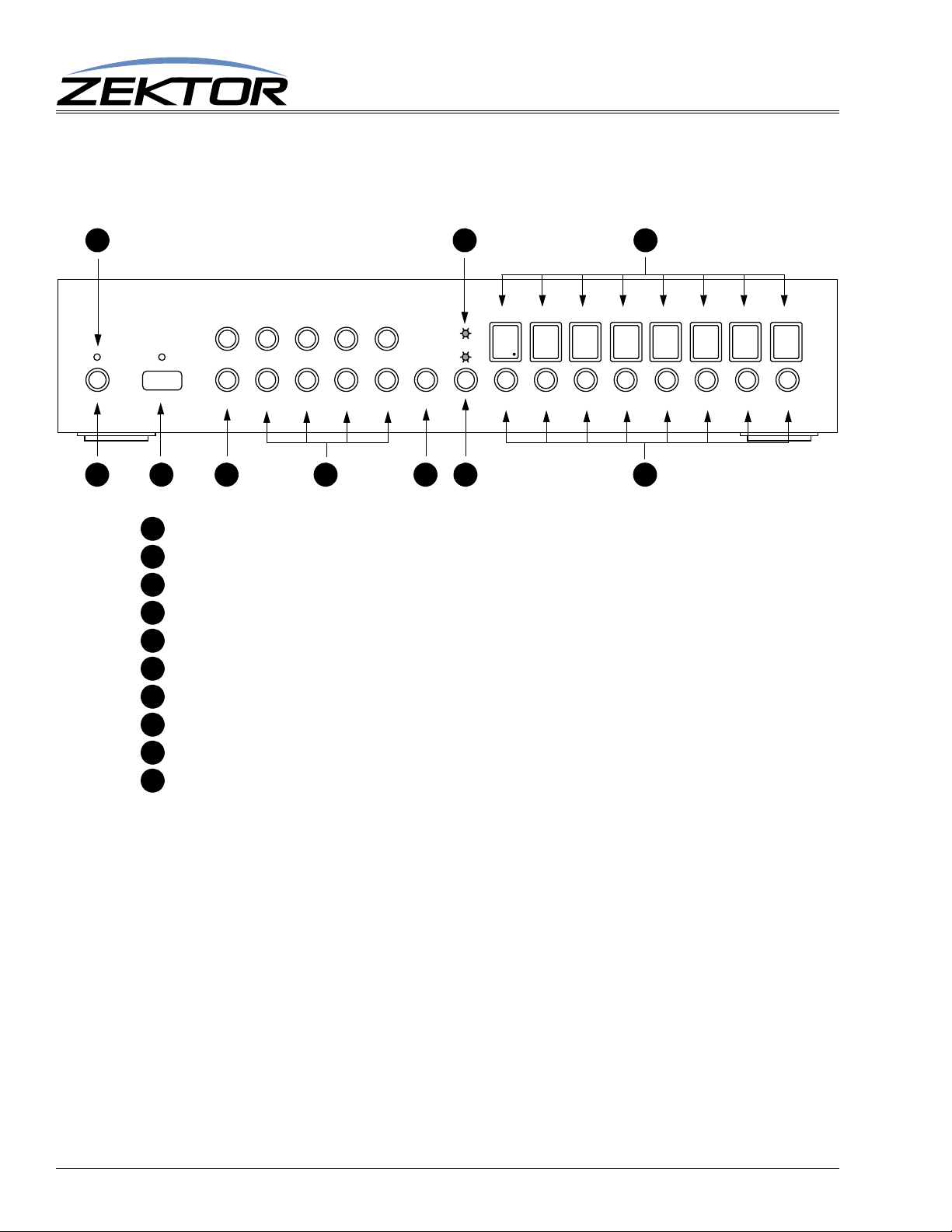
Front Panel Controls
Power toggle / extended setup button.
Front Panel Control and Connections
Window for IR sensor.
Clear button and memory buttons.
Input selection buttons 1-8.
Enter button.
Audio / video breakaway selection button.
Zone selection buttons 1-8.
Power indicator / IR received.
Audio / video breakaway LEDs.
Current input mappings for each zone.
8
ClarityHD8x8 User Guide, Version 1.1, 6/7/13
Page 9
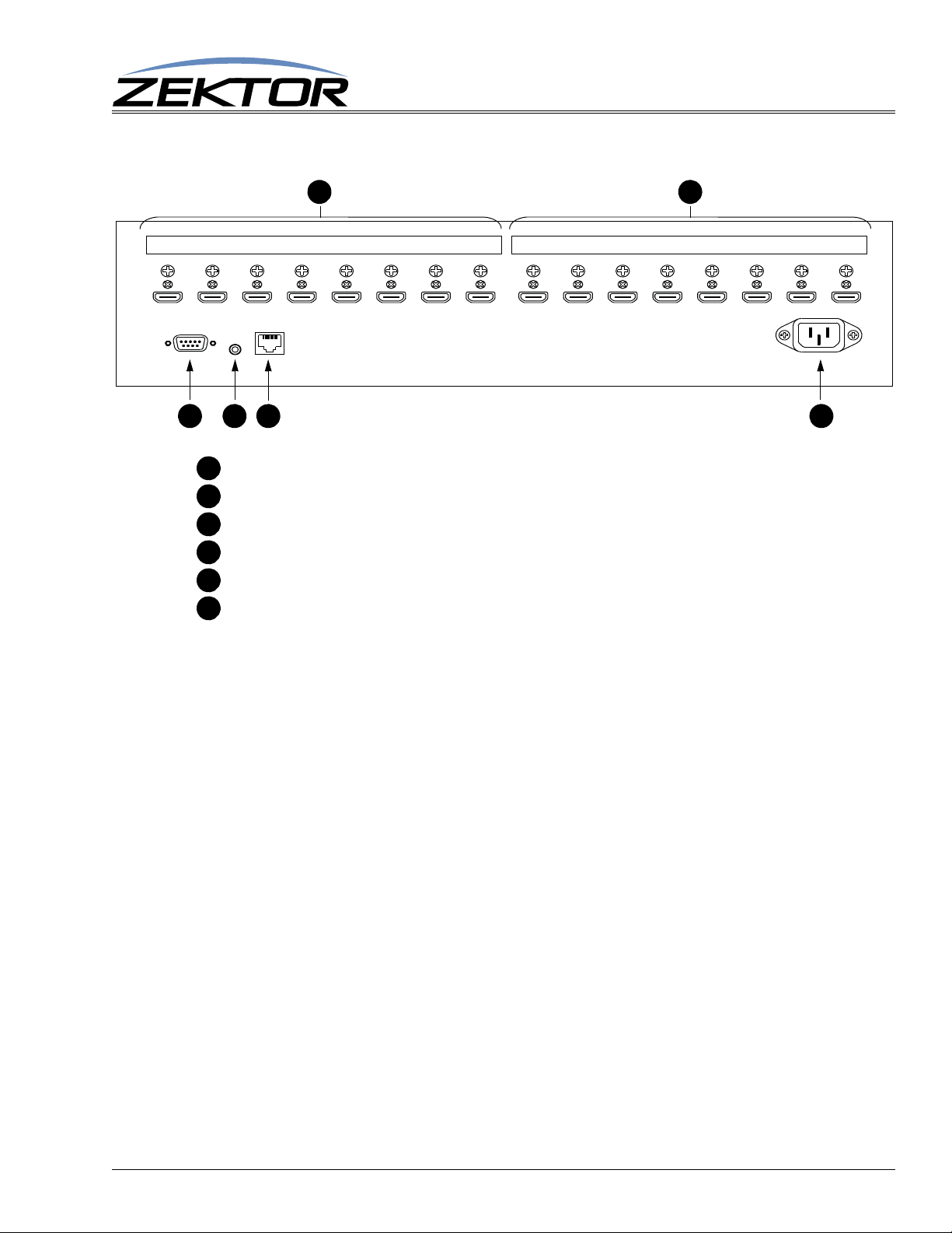
Rear Panel Connections
INPUT-1 INPUT-2 INPUT-3 INPUT-4 INPUT-5 INPUT-6 INPUT-7 INPUT-8 OUTPUT-8 OUTPUT-8 OUTPUT-8 OUTPUT-8 OUTPUT-8 OUTPUT-8 OUTPUT-8 OUTPUT-8
RS-232
WWW.ZEKTOR.COM
SAN DIEGO, CA
MADE IN USA
~110-240V
.45A MAX
50-60 Hz
IR
TCP/IP
FD
BA
C E
ABCDE
F
HDMI inputs.
HDMI outputs.
RS-232 connection.
Front Panel Control and Connections
Hardwired IR jack. Optical isolated, polarity insensitive, 3V to 15V levels.
TCP/IP connection.
Power receptacle.
ClarityHD8x8 User Guide, Version 1.1, 6/7/13
9
Page 10

Front Panel Control and Connections
A
AUDIO VIDEO MATRIX SWITCH
AUD
VID
MEM 1 2 3 4
CLR 5 6 7 8 ENT 1 2 3 4 5 6 7 8
A C
D
B
CDB
Turning the ClarityHD8x8 on or off
To turn the ClarityHD8x8’s power on, press the POWER toggle button.
To turn off the ClarityHD8x8’s power, press AND HOLD the power button for 2 seconds, and the
ClarityHD8x8 will power down.
Mapping an input to an output zone
To map any input to any zone (output):
1 Select the zone or zones to be mapped by pressing one or more of the zone buttons . When
a zone is selected the zone’s LED will flash and its decimal point will light up. By pressing a flashing zone’s button again, you can unselect the zone.
2 Once a zone (or zones) have been selected, pressing an input button , maps the chosen
input to the selected zone(s).
3 The zone LED(s) will stop flashing, but will remain selected, (the decimal point will remain
lit). To remap the currently selected zone(s) to a different input, simply press another input
button.
Audio and video inputs will only change when the proper VID and AUD LEDs are lit, see the next section
on audio / video break away for more information.
10
ClarityHD8x8 User Guide, Version 1.1, 6/7/13
Page 11

Functional Overview
The ClarityHD8x8 switch is a full featured HDMI switch. It caches EDID settings and HDCP keys. By
caching the EDID and HDCP keys, the switch can quickly switch between sources without flicker or
video blanking.
HDMI Overview
HDMI has many issues associated with its distribution. It was originally designed to connect a DVD
player to a TV, with a few tweaks to the specification to allow for limited distribution.
HDCP Keys
HDMI allows for encrypted audio/video streams to be sent over the HDMI cables. To do this, each
receiving TV or monitor must be issued its own decryption key. This forces each HDMI cable to send
a different stream of encrypted data, even if it’s the same program being sent to two different monitors.
This prevents a simple splitter from working, since a simple splitter would send the same stream to two
different monitors.
This also allows the source (DVD player, Cable Box, etc) to determine the number of simultaneous
monitors allowed to view it’s content. Some cable box manufacturers only supplied a single HDCP
key, while some Blu-ray players supplied a very limit number (like 3). Even today there are manufac
turers that limit the number of HDCP keys, in their Blu-ray players to 9.
Overview
Overview
-
T o work around this problem, the ClarityHD8x8 will cache keys from sources and generate keys when
needed, to supply up to 24 HDCP keys.
When a source runs out of HDCP keys (there are more monitors attempting to view a source than there
are keys), it can do a number of undefined things. Video can go blank, or it can flash on and off, or in
some rare cases the source could even lock up and need to be power cycled.
If you suspect an HDCP problem, you can verify this by:
• Turning off the ClarityHD8x8
• Turn off all TVs and monitors connected to the ClarityHD8x8
• Turn on the ClarityHD8x8 and set all zones to point to the source with the suspected HDCP
problem.
• Now start turning on zones. If the disp lay starts flickering o r blanking after you tu rn on a zone,
then the source most likely has one less HDCP key that the number of zones you have turned
on.
• To remedy the HDCP problems, see the section on setting the number of HDCP keys. (See:
“‘KSIZI’ Set the number of HDCP keys of a source” on page 28.)
For the most part there are fewer and fewer HDCP key issues with the newer HDMI products, and usually nothing needs to be done for the switch to work out of the box.
ClarityHD8x8 User Guide, Version 1.1, 6/7/13
11
Page 12

Validating the installation of the ClarityHD8x8
After all sources and zones are connected, you should perform the following series of steps to verify
everything is working ok, and to lock in the HDCP and EDID changes.
• Be sure the EDID is unlocked. (See: “‘EDLO’ EDID Lock” on page 28.)
• T urn on all sources, all TV / Monitors, and all receivers. Set the sources to “protected” content
if possible. (Play a Hollywood DVD -- not a copy. Set the cable boxes to a premium channel
like HBO. Etc.)
• Switch all the zones to each of the sources. (See: “Mapping an input to an output zone” on
page 10.)
• Wait for all pictures to stabilize on each source change, verify that a picture can be seen on all
zones. There can be a lot of video blanking and flickering at this point, and if you have sources
that have manual HDCP key count settings, this could take a while. Verify that all sources can
be seen on all zones.
• You should now be able to switch a single zone between different sources without causing
flickering on any of the other zones.
• If you have a receiver attached to any of the output zones, you should lock the EDID. (See:
“‘EDLO’ EDID Lock” on page 28.)
• After locking the EDID settings, you should be able to turn off and on receivers without causing flickering on any of the zones.
Overview
• You should now save the EDID settings in EEPROM so that all the HDCP keys and EDIDs
cached will not be lost when power is turned off. (See:
tings” on page 25.)
• Before adding or removing any sources or zones, be sure to unlock the EDID. When the EDID
is locked, the switch will ignore all new devices or changes, so it must be unlocked to register
any changes.
“‘SS’ Save Default Power On Set-
12
ClarityHD8x8 User Guide, Version 1.1, 6/7/13
Page 13

RS-232 / TCP/IP Port Hardware
TCP/IP Overview
The Serial and TCP/IP port share the same protocol.
The TCP/IP connection is a very simple socket, sometimes referred to as Raw TCP/IP socket, similar
to T elnet, but without the Telnet protocol overhead. Most telnet clients will allow you to telnet into the
ClarityHD8x8 without error.
We use the open source package PuTTY to do our testing. It has a convenient “Raw” mode that works
great with the ClarityHD8x8, and is available in Windows and Linux (with a Mac O/S version in the
works). (We are not associated with PuTTY in anyway, but do find it a useful tool when communicat
ing over TCP/IP and Serial port connections)
Website: http://www.chiark.greenend.org.uk/~sgtatham/putty
The default IP address is 192.168.1.200 and the port is 50005. The serial command “^IPA
xxx,xxx,xxx,xxx$” (See:
IP address, the port number is fixed at 50005.
Once a connection is made it will remain open until closed by the client, or after 10 minutes of retries
at attempting to talk to the client.
“‘IPA’ Set / View TCP/IP Address” on page 27) can be used to change the
RS-232 / TCP/IP Port Hardware
-
After connecting to the TCP/IP port, all commands are identical to those of the Serial port. All strings
coming from the ClarityHD8x8 will be sent to both the TCP/IP and Serial port.
The ClarityHD8x8 will accept commands from both the Serial and TCP/IP simultaneously, each command will be buffered until the ending ‘$’ is read, at which time the commands will be executed in the
order received. All responses will be sent to both the Serial port and TCP/IP connections.
TCP/IP settings used by the ClarityHD8x8
Default IP Address: 192.168.1.200
Port Number: 50005
Duplex: Full
Speed: 10/100 Mbps
RS-232 Pinout and Baudrate Settings
The RS-232 port on the ClarityHD8x8 is the same format, and pinout, as a PC modem, and uses the
same type of cable as a standard serial modem would, which is a standard straight through cable. Do
not use a cable that is marked as a “Null Modem” cable.
The ClarityHD8x8 can also be used with USB to RS-232 conversion cables, these are all typically
straight through cables. (Be sure to install any drivers that come with the USB to RS-232 cable you are
using.)
The RS-232 port is a female type DE-9 connector (sometimes mistakenly referred to as a DB-9 connector) with the following pinout:
ClarityHD8x8 Serial Protocol, Version 1.1, 6/7/13
13
Page 14

Pin definitions
1 - No Connect 6 - No Connect
2 - TX 7 - No Connect
3 - RX 8 - No Connect
4 - No Connect 9 - No Connect
5 - GND
Port settings used by the ClarityHD8x8
Baudrate: 19200
Data Bits: 8
Stop Bits: 1
Parity: NONE
RS-232 / TCP/IP Port Hardware
Timing information (unless specified otherwise by a command’s description)
Min character to character time: 0ms
Min line to line time: 0ms
Min time between commands: 0ms
Max time to respond to a request: 100ms
14
ClarityHD8x8 Serial Protocol, Version 1.1, 6/7/13
Page 15

Command Syntax
Command Syntax
The ClarityHD8x8 serial command set uses an ASCII based protocol and a terminal emulator can be
used to test the serial port of the ClarityHD8x8.
Each serial command is formatted as:
^CMD param1,param2,...$
Where:
^ = All commands and responses start with the ‘^’ character.
CMD = The name of the command.
param = Any number of parameters can follow a command.
$ = All commands and responses end with the ‘$’ character.
For instance the name of the command to turn power on / off is ‘P’ (must be capitalized) therefore, to
turn on the ClarityHD8x8 send:
^P 1$ -> Command sent to the A/V switch
^+$ <- Acknowledgment indicating valid command
^=P 1$ <- Response from the A/Vswitch for new setting
Command Syntax
to turn off the ClarityHD8x8 send:
^P 0$ -> Command sent to the A/V switch
^+$ <- Acknowledgment indicating valid command
^=P 0$ <- Response from the A/V switch for new setting
NOTE: Only the characters between ‘^’ and ‘$’ are valid, any characters sent before the ‘^’ or after the ‘$’
will be ignored.
NOTE: By default, the ClarityHD8x8 adds a carriage return and a line feed to the end of its responses, after
the ‘$’. This makes testing with terminal software easier. Since they are outside the ‘^’ and ‘$’ char
acters, they should be ignored by software drivers. If desired, this behavior can be disabled. (See:
“‘XS’ Control Settings” on page 23)
Command Responses
Type of Responses and Timing Information
There are three different types of responses: Acknowledgements, Errors and Query Strings.
By default, the ClarityHD8x8 will always respond to a command, there are no “time-out” modes, if
you send a command and don’t get a response within 100ms, something’s wrong with the connection.
The Acknowledgement Response
Every command will be followed by an acknowledgement or error response.
-
Anytime you issue a command and there are no errors, you will receive the acknowledgement
response. Which is:
^+$
ClarityHD8x8 Serial Protocol, Version 1.1, 6/7/13
15
Page 16

Command Syntax
The Error Response
Every command will be followed by an acknowledgement or error response.
If something is wrong with the command, you will get an error response. Which is
^!<error_number>$
which is the ‘!’ followed by an error number (in ASCII), followed the ‘$’ character.
For instance ‘2’ is not allowed as a parameter in the ‘P’ (power) command, so:
^P 2$ -> Command sent to A/V switch
^!2$ <- Error response to an out of range parameter
which indicates there was an out of range parameter.
The following are the Error Response codes that can be returned by the ClarityHD8x8:
1 - Unrecognized command.
2 - A parameter was out of range.
3 - Syntax error, or a badly formed command.
4 - Checksum error.
5 - Too many or too few parameters.
6 - Device busy, cannot process command.
7 - Buffer overflow.
8 - Command not valid if device is not powered on.
100 - Error initializing the HDMI subsystem.
And some more detailed descriptions of their meanings:
Error 1 - The command given was not recognized as a ClarityHD8x8 command. Commands are case
sensitive and in the ClarityHD8x8, all commands are upper case.
Error 2 - One of the parameters given was too large, or too small, the command will be ignored.
Error 3 - Something was wrong with the command's syntax. There was possibly extra data at the end
of the line, or non-decimal data as part of a parameter. There cannot be whitespace before or
after a checksum or CRC-8 checkcode, or this error will be returned.
Error 4 - The ':' character was used to indicate a Checksum was appended to the command string, but
the Checksum did not match the calculated one. The command will be ignored.
Error 5 - The number of parameters given does not match the number allowed by this command.
Error 6 - To prevent conflicts between the front panel Setup Mode and the serial port settings, when
the ClarityHD8x8 is in the Setup Mode, many parameters become read only and any attempt at
writing them will return Error 6. Issuing the “Key Emulation” command with key code ‘0’ can
be used to exit the Setup Mode, at which point the command can be re-issued without an Error
6 response.
Error 7 - An internal buffer has overflowed, for instance more than 16 key codes were sent as part of
the “Key Emulation” command.
Error 8 - Power to the device must be ‘ON’ before this command is allowed.
Error 100 - An error occurred while initializing the HDMI sub-section.
The Query Response
The query response is sent by the ClarityHD8x8 to indicate a setting has changed, or as a response to a
query command. The query response string consists of the ‘=’ character followed by the command
string of the command being queried.
16
ClarityHD8x8 Serial Protocol, Version 1.1, 6/7/13
Page 17

For instance, in the case of the power command:
^P ?$ -> Send a power request command to the A/V switch
^+$ <- Acknowledgement (the command has no errors)
^=P 1$ <- Query response indicating the power is on.
Using Bitmapped Parameters
Reading / Writing Bitmapped Parameters
Some commands accept “Bitmapped” parameters. These are decimal values that represent a series of
flags, or bits, that control, enable and/or disable different device operations.
Binary arithmetic is used to represent bitmapped parameters, it is assumed the reader has some familiarity with binary arithmetic.
An example of a command that uses a bitmapped parameter is the “XS settings” command, which is
defined as:
^XS settings$
Where ‘settings’ is a bitmapped parameter defined as:
Command Syntax
Valu e
Bit Position
Name
Default:
32768 16384 8192 4069 2048 1024 512 256 128 64 32 16 8 4 2 1
15 14 13 12 11 10 9 8 7 6 5 4 3 2 1 0
AMU VMU 12V AON IRJ IRS IRE KYE CHG SET CSE CRE CHN ECO ACK ASY
1 0 0 1 1 1 0 0 1 1 0 1 0 1 1 1
For information on what each bit of the XS command does, see: “‘XS’ Control Settings” on page23.
The “Value” row, in the table’s header, refers to the values, that when added together, create the decimal parameter used by the command. For instances if you want the bits ‘ASY’ and ‘IRS’ to be set to 1,
and the rest of the bits set to zero, the parameter’s value would be calculated as: 1+1024, making the
parameter value: 1025.
The command to set those two bits to ones, and reset all the others would be:
^XS 1025$
Individual bits of a bitmapped parameter can be set or reset without affecting the other bits, by prefixing the bitmapped parameter with a ‘+’ to set individual bits, or a ‘-’ to reset individual bits.
For instance in the above example the bitmapped value has been set to 1025. If we would now like to
enable the IR jack, by setting the ‘IRJ’ bit, the following command can be issued:
^XS +2048$
The will set the ‘IRJ’ bit, and have no affect on the others, and the new “XS” value would b e: 3073
If we’d like to now disable the IR jack and the IR sensor, by clearing the ‘IRJ’ and ‘IRS’ bits, we’d use
the value “2048+1024, or 3072 and issue the command:
^XS -3072$
leaving the new “XS” value to be: 1.
ClarityHD8x8 Serial Protocol, Version 1.1, 6/7/13
17
Page 18

Basic Control
Reference for Basic Control Commands
These commands are all that are needed for basic control of the ClarityHD8x8 and includes power on/
off, remapping sources to zones. This section also includes some helpful control options for changing
the way serial commands behave.
Definitions
The following terms are used through out this manual.
Zone
An output. The ClarityHD8x8 has eight (8) outputs, known as zones. A single zone consists of the
combination of a HDMI video channel, and an HDMI audio channel. For most commands, zones are
indicated by using a ‘
Input
An input, or source. The ClarityHD8x8 has eight (8) HDMI inputs, each consists of the combination of
an HDMI video channel and an HDMI audio channel. For commands that mix inputs with zones,
‘inputs’ are indicated by numbers without a ‘
@’ prefix character.
Basic Control
@’ prefix.
Channel
A channel is an HDMI video path, or an HDMI audio path. Channels are used to control breakaway
features.
The following channels are supported by the ClarityHD8x8:
1 - HDMI audio/video channel.
8 - Reserved.
18
ClarityHD8x8 Serial Protocol, Version 1.1, 6/7/13
Page 19

Basic Control Commands
Command Description Comments
P p Power control p=power state (0=off, 1=on, +=toggle).
PT s Set power down timer s=Seconds (0=disabled).
SZ @z,i Set zones to inputs @z=Zone (1-8), i=Input (1-11,+,-).
SZ.ch @z,i Set zones to inputs with
breakaways
DUPZ @z,dz Duplicate zones @z=Zone (1-8), dz=Zone to copy (1-8).
DUPZ.ch @z,dz Duplicate zones with break-
aways
MZ @z,m Mute zone @z=Zone (1-8), m=Mute (0=Disabled (muted), 1=Enabled, +=Toggle).
MZ.ch @z,m Mute zones w/breakaway ch=Channel(s) (1-7), @z=Zone (1-8), m=Mute (0,1,+).
Q ? Query for status Returns: Operating status flags (see text).
QSZ ? Query setting change bitmap Returns: A bitmap of the zones that have had their input settings changed.
QMZ ? Query mute change bitmap Returns: A bitmap of the zones that have had their mute settings changed.
Table 1: Basic Control Commands
ch=Channel(s) (1-7), @z=Zone (1-8), i=Input(s) (1-11,+,-)
ch=Channel(s) (1-7), @z=Zone (1-8), dz=Zone to copy (1-8)
Basic Command Definitions
Basic Control
‘P’ Power Control
Turn on / off, or toggle the power state of the ClarityHD8x8:
^P 0$ Turn off power if power is not locked on.
^P 1$ Turn on power.
^P 2$ Turn off power regardless of “locked” state.
^P 3$ Turn on power and lock it on -- only a “P 2” command can turn off power.
^P +$ Toggle power
^P ?$ Query for current setting
Response String:
^=P n$
Where:
n = Current power status, 0=Off, 1=On, 3=Locked On. (A value of ‘2’ is never returned.)
The power lock and unlock can be used to keep a controller from turning off the ClarityHD8x8.
Drivers should be written to only use the “P 0” and “P 1” commands to turn on and off the
ClarityHD8x8. This allows users to override the driver’s logic by manually issuing the “P 2” and “P 3”
commands.
By issuing a “P 3” command (lock power on), the ClarityHD8x8 will be turned on, and locked. Only a
subsequent “P 2” command will turn off the ClarityHD8x8, The “P 0” and “P 1” commands will be
ignored.
‘SZ’ Set Zone(s)
This is the command used to map sources to any number of zones.
Its different forms are:
ClarityHD8x8 Serial Protocol, Version 1.1, 6/7/13
19
Page 20

^SZ @zone,@zone,in$ Map all channels of an source, to a zone or zones.
^SZ.ch @zone,in$ Map only the selected channels of sources to zones.
^SZ.ch @zone,+$ Sequence zones forward through sources.
^SZ.ch @zone,-$ Sequence zones in reverse through sources.
^SZ ?$ In polled mode, reads current settings of all logged changes.
^SZ @zone,?$ Read current settings of given zones.
^SZ.ch @zone,?$ Read current settings of the selected channels of zones.
Response Strings:
^=SZ @zone,in$ or,
^=SZ.ch @zone,in$
Where:
@zone = One (or more) zones to be mapped.
in = Source to map to given zone(s).
ch = Channel bitmap.
‘SZ’ Examples
The ‘SZ’ command in its simplest form:
^SZ @1,@3,2$
Basic Control
maps the input ‘2’ to the zones ‘1’ and ‘3’. You can also map multiple zones and inputs using a single
command. For instance:
^SZ @1,2,@3,@5,7$
maps the input ‘2’ to zone ‘1’, and also maps the input ‘7’ to zones ‘3’ and ‘5’.
‘SZ’ Query Examples
T o make parsing the response strings easier , only one response string is sent per zone. Or , in the case of
channel breakaways, only one response string per channel is returned. The response string is sent as a
fixed length string using leading zeroes.
You can request the mapping of multiple zones, with one command, and still only one response string
per zone will be returned, for instance:
^SZ @1,@3,@4,?
could return:
^+$ <- Indicates no errors in the command
^=SZ @001,002$ <- All channels of input ‘2’ mapped to zone ‘1’
‘MZ’ Mute (Disconnect) Zone(s)
This is the command used to mute, or disconnect a zone from any source. When muted, video is turned
off, leaving a black screen. (Or possibly blue screen, depending upon how your receiver acts when
video has been turned off.)
20
The different forms of the MZ command are:
^MZ @zone,@zone,mute$ Mute all channels of a zone or zones.
^MZ ?$ In polled mode, reads current settings of all logged changes.
^MZ @zone,?$ Read current settings of given zones.
Response Strings:
ClarityHD8x8 Serial Protocol, Version 1.1, 6/7/13
Page 21

Basic Control
^=MZ @zone,mute$ or,
Where:
@zone = One (or more) zones to be mapped.
mute = Mute setting (0=Unmuted, 1=Muted).
‘MZ’ Examples
The ‘MZ’ command in its simplest form:
^MZ @1,@3,1$
mutes all channels of the zones ‘1’ and ‘3’. You can also mute/unmute multiple zones using a single
command. For instance:
^MZ @1,1,@3,@5,0$
mutes zone ‘1’, and unmutes zones ‘3’ and ‘5’.
By appending a ‘.’ and a channel bitmap to the ‘MZ’ command, the command can also be used to mute
individual channels.
‘MZ’ Query Examples
There are two forms of the query response string, depending upon whether any channel breakaway
options are in affect.
For instance if HDMI video, digital audio, and HDMI audio, are all muted on zone ‘1’, then:
^MZ @1,?$ >- Query request sent to the A/V switch
would respond with:
^+$ <- Indicates no errors in the command
^=MZ @1,1 <- Video and all audio channels are muted on zone ’3’
T o make parsing the response strings easier , only one response string is sent per zone. Or, in the case of
channel breakaways, only one response string per channel is returned. The response string is sent as a
fixed length string using leading zeroes.
You can request the settings of multiple zones, with one command, and only one response string per
zone will be returned, for instance:
^MZ @1,@3,@4,?
could return:
^+$ <- Indicates no errors in the command
^=MZ @001,1$ <- All channels of zone ‘1’ are muted
^=MZ @003,0$ <- All channels of zone ‘3’ are not muted
ClarityHD8x8 Serial Protocol, Version 1.1, 6/7/13
21
Page 22

Advanced Control
Reference for Advanced Control Commands
These commands are for more advanced control over the ClarityHD8x8 , including front panel light
intensities, changes to serial port behavior, etc.
Advanced Control Commands
Command Description Comments
! Get most recent error code Returns: Most recent error code, or error code 0’ if no error.
V ? Get version string Returns: Product name and firmware version string.
LI mode,dim,bri,off Sets LED intensities mode=Mode (0=off, 1=dim, 2=bright, 3=auto), dim,bri,off=Dim, Bright and Off levels (0-100).
QI ? Query for capability information Returns: Number of zones & inputs, and a full channel mask.
XS flags Control settings Set / reset control options. flags=Control option flags (see text).
XE flags Transmit enable flags Enable commands to asynchronously send there status. flags=Enable flags (see text).
SS flags Save Settings Save specified settings as initial power on values. flags=Indicate which settings to save.
IPA xxx,xxx,xxx,xxx View or change TCP/IP address View the current address, or chan ge it.
FS 246 Reset to factory settings Resets ALL values to initial factory settings!
Advanced Control
Table 2: Advanced Control Commands
Advanced Command Definitions
‘!’ Resend Error Code
This special purpose command is used to request that the ClarityHD8x8 resend the last error code sent.
This can be useful if the last error code sent had a checksum appended to it that did not match.
^!$ Request that the last error code sent, be resent
‘V’ Version
Returns the current firmware version of the ClarityHD8x8.
^V ?$
Response String:
^=V “ClarityHD8x8”,1.0a,30B2S12345678$
Where:
“Clarity 8x8” = Model
1.0a = Firmware version
30B2S12345678 = Serial number
‘QI’ Query for Zone, Input and Channel Information
Returns the number of zones, and inputs, and a mask of the channels available on the ClarityHD8x8.
^QI ?$
Response String:
^=QI zones,inputs,chan_bitmap$
22
ClarityHD8x8 Serial Protocol, Version 1.1, 6/7/13
Page 23

Where:
zones = Number of available zones
inputs = Number of available inputs
chan_bitmap = Bitmap of the available channels
‘XS’ Control Settings
Turn on and off operational modes of the ClarityHD8x8.
The format of the command is:
^XS settings1,settings2$ Set the control bits to ‘settings1’ and ‘settings2’
^XS +settings1,+settings2$ Set bits indicated in ‘settings1’ and ‘settings2’ to 1
^XS -settings1,+settings2$ Reset bits indicated in ‘settings1’ and ‘settings2’ to 0
^XS ?$ Query for current settings
Response String:
^=XS settings1,settings2$
Where ‘settings1’ is a bitmapped parameter defined as:
Advanced Control
Valu e
Bit Position
Name
Default:
Valu e
Bit Position
Name
Default:
32768 16384 8192 4069 2048 1024 512 256 128 64 32 16 8 4 2 1
15 14 13 12 11 10 9 8 7 6 5 4 3 2 1 0
0 0 0 KYD IRJ IRS 0 0 CHS SET 0 CRE CHM ECO ACK ASY
0 0 0 0 1 1 0 0 1 1 0 1 0 1 1 1
ASY - 0=Polled mode. 1=Asynchronous Mode.
ACK - 0=Don’t acknowledge cmds with “^+$” 1=Acknowledge error free commands with a “^+$”
ECO - 0=Do not send a response strings for each cmd. 1=Always send response string when a serial command is issued
CHM- 0=Only send a “.ch” when needed. 1=Always append a “.ch” channel mask to a zone response cmd
CRE - 0=Don’t send CRs/LFs at end of responses 1=End all responses with a carriage return and a line feed.
SET - 0=Disable the setup option. 1=Enable the setup option.
CHS - 0=Setup mode is read only. 1=Enable changing parameters in the setup mode.
IRS - 0=Disable IR sensor. 1=Enable IR sensor.
IRJ - 0=Disable IR jack. 1=Enable IR jack.
KYD - 0=Font panel keys not disabled. 1=Disable front panel keys.
0- Reserved.
Where ‘settings2’ is a bitmapped parameter defined as:
32768 16384 8192 4069 2048 1024 512 256 128 64 32 16 8 4 2 1
15 14 13 12 11 10 9 8 7 6 5 4 3 2 1 0
0 0 0 0 0 0 0 0 0 0 0 0 0 0 0 0
0 0 0 0 0 0 0 0 0 0 0 0 0 0 0 0
0- Reserved.
This command uses a bitmapped parameter. Each bit can set or reset without affecting the other bits.
“Using Bitmapped Parameters” on page 17, for more information on using bitmapped parame-
(See:
ters.)
Both parameters do not have to be present on the command line, if a parameter is left out the command, it will be left unchanged:
^XS settings1$ Only ‘settings1’ is changed
Since ‘settings2’ was not present on the command line, it will not be affected.
A comma can be used to indicate a missing parameter:
ClarityHD8x8 Serial Protocol, Version 1.1, 6/7/13
23
Page 24

Advanced Control
^XS ,settings2$ Only ‘settings2’ is changed
Since ‘settings1’ was not present on the command line, it will not be affected.
The following paragraphs define each option in more detail:
‘ASY’ Set the Polled or Asynchronous Mode
With this bit set, the ClarityHD8x8 is in the asynchronous mode, which simply means each time a state
changes, like the power being toggled, the ClarityHD8x8 will send a response string immediately out
the serial and TCP/IP ports.
‘ACK’ Enable / Disable Acknowledgements
Each time a command is sent to the ClarityHD8x8, the ClarityHD8x8 responds with either an error
message, if there was a problem with the command, or an acknowledgement string of “
behavior can be changed by setting this bit to ‘0’. If the bit is reset, the “
‘ECO’ Enable / Disable the ‘Parameter Changed’ Strings
Each command that makes a change to a parameter , will be echoed with a response string that indicates
the new values of the parameters changed. The response strings are only issued after the changes have
taken affect, and reflect the new state of the ClarityHD8x8.
^+$” string will not be sent.
^+$”. This
With this bit set to ‘0’, these response strings will not be sent. To verify the new settings, the controller
must read the new values manually.
‘CHM’ Enable / Disable always sending“.ch” masks on zone commands
On commands that change zone settings (‘SZ’, ‘MZ’, ‘DZ’), the “.ch” channel mask is only sent when
needed to indicate a difference in settings between channel. With this bit set, the “.ch” mask will
always be sent, regardless of any differences between channel settings.
If you plan on using the ClarityHD8x8’s breakaway functions, setting this bit can make parsing the
response strings easier, since only one type of response string will be returned.
‘CRE’ Enable / Disable trailing Carriage Returns Line Feeds
A carriage return and line feed can be appended to all responses coming from the ClarityHD8x8. This
is useful when using terminal software to test command strings.
Since the carriage returns and line feeds are sent outside of the normal string (they are sent after the
ending ‘
can be turned off by setting this bit to a ‘0’.
‘SET’ Enable / Disable the Setup Mode
This bit can be used to disable the ability to enter the setup mode, preventing a casual user from enter
the setup mode and making changes, or reassigning presets, etc.
‘CHS’ Enable / Disable making changes in the Setup Mode
$’), they should be ignored by the controller . But if there are problems with this behavior, they
This bit allows a user to enter the setup mode, and view settings, but does not allow any changes to be
made.
‘KYD’ Disable front panel Keys
Setting the ‘KYD’ to ‘1’ will disable the front panel, all key presses will be ignored.
24
ClarityHD8x8 Serial Protocol, Version 1.1, 6/7/13
Page 25

‘IRS’ Enable / Disable Front Panel IR Sensor
Setting the ‘IRS’ bit to ‘0’, disables the IR sensor on the front panel. This has no affect on IR signals
being received through the rear panel IR jack. This is useful in preventing stray IR from affecting the
ClarityHD8x8 when only the rear IR jack is being used.
‘IRJ’ Enable / Disable Rear Panel IR Jack
Setting the ‘IRJ’ bit to ‘0’, disables the IR jack on the rear panel. This has no affect on IR signals being
received through the front panel IR sensor. The best way to disable the IR jack is to simply unplug
whatever it is you have plugged into it.
It’s no t usually a problem having both the front panel IR sensor and the Rear panel IR jack enabled. IR
will be accepted from either. If both the front panel IR sensor, and the rear panel IR jack received sig
nals simultaneously, the rear panel jack will have priority.
If a controller is constantly sending data to the rear panel jack, this can effectively jam the front panel
sensor. Setting this bit to ‘0’ will disable the rear panel jack and allow the front panel sensor to operate
normally. Though once again, it might be better to just unplug the rear panel IR jack if it’ s not going to
be used.
‘SS’ Save Default Power On Settings
When all power is lost to the ClarityHD8x8 (for instance the power cord is unplugged), the current settings will be lost. When power is restored all settings will be set to their initial values. This command
allows you to change those initial values.
Advanced Control
-
Valu e
Bit
T o use this command, the ClarityHD8x8 should be set to the values that are to be used as the initial values.
Once the current settings are in place, this command is issued to save the current settings as the initial
values.
This command uses a bitmapped parameter to indicate which values are to be saved. A bit set to ‘1’
indicates the associated setting should be saved, a bit set to ‘0’ indicates the setting should not be saved
and the previously saved setting will remain unchanged.
Command formats:
^SS settings$ Set the enable bits to ‘settings’
Response String:
There is no response string to the SS command, this command is write only.
Where ‘settings’ is a bitmapped parameter defined as:
32768 16384 8192 4069 2048 1024 512 256 128 64 32 16 8 4 2 1
15 14 13 12 11 10 9 8 7 6 5 4 3 2 1 0
Bit-0 - Save zone input/output mappings, and power state
Bit-1 - Save switching delay times
Bit-2 - Save LED levels and mode
Bit-3 - Save control settings (the XS command settings)
Bit-5 - Save IP parameters
Bit-15 - Save HDMI settings: EDID and HDCP caches, HDCP key counts, and the EDID lock state.
Note: The ClarityHD8x8 must be powered on before sending the “Save HDMI settings” (Bit-15).
All other bits are reserved and should be set to 0 when issuing this command.
ClarityHD8x8 Serial Protocol, Version 1.1, 6/7/13
25
Page 26

‘FS’ Reset to Factory Settings
This command will reset selected parameters of the ClarityHD8x8 to their factory default settings.
This command uses a bitmapped parameter to indicate which values are to be reset. A bit set to ‘1’
indicates the associated setting should be reset, a bit set to ‘0’ indicates the setting should not be reset
and the previous setting will remain unchanged.
Command formats:
^FS settings$ Reset the parameters indicated by ‘settings’
Response String:
There is no response string to the FS command, this command is write only.
Where ‘settings’ is a bitmapped parameter defined as:
Advanced Control
Valu e
Bit
32768 16384 8192 4069 2048 1024 512 256 128 64 32 16 8 4 2 1
15 14 13 12 11 10 9 8 7 6 5 4 3 2 1 0
Bit-0 - Reset zone input/output mappings, and power state
Bit-1 - Reset switching delay times
Bit-2 - Reset LED levels and mode
Bit-3 - Reset control settings (the XS command settings)
Bit-5 - Reset IP parameters
Bit-15 - Reset HDMI settings: Clear EDID and HDCP caches, clear HDCP key counts and the EDID lock state.
Note: The ClarityHD8x8 must be turned on before sending the “Reset HDMI settings” (Bit-15), and
the switch must be power cycled (using the ‘P 0’ and ‘P 1’ commands) before the cleared settings take
affect.
All other bits are reserved and should be set to 0 when issuing this command.
‘LI’ Lighting Mode and Intensities
This command uses a bitmapped parameter. Each bit can set or reset without affecting the other bits.
“Using Bitmapped Parameters” on page 17, for more information on using bitmapped parame-
(See:
ters.)
Allows changing the behavior of the front panel LEDs, and adjusting their intensities.
^LI mode,dim,bright,off$ Set mode and intensities
^LI ?$ Query for current settings
Response String:
26
^=LI mode,dim,bright,off$ Set mode and intensities
Where:
mode = Lighting mode (Settings: 0=Off, 1=Dim, 2=Bright, 3=Auto-dim)
dim = Intensity of dimmed LEDs (Range: 0-100)
bright = Intensity of brightened LEDs (Range: 0-100)
off = Intensity of the standby power LED (Range: 0-100)
Response Example:
^=LI 3,020,090,010$ Mode=Auto, dim=20%, bright=90%, off=10%
The mode settings allow you to set the front panel LEDs to always be: 0 - off, 1 - Always at the ‘dim’
intensity , 2 - always at the ‘bright’ intensity, or 3 - auto-dim from ‘bright’ to ‘dim’ when the front panel
is not in use.
The intensities range for 0, which of off, to 100, which is full intensity.
ClarityHD8x8 Serial Protocol, Version 1.1, 6/7/13
Page 27

When setting parameters, not all parameter have to be present, if a parameter is not present, it will be
left unchanged. For instance to change just the ‘bright’ value to 50%:
^LI ,,50$ -> Set the ‘bright’ intensity to 50%
Only the ‘bright’ intensity is affected.
‘IPA’ Set / View TCP/IP Address
The command format is:
^IPA xxx,xxx,xxx,xxx$ Set new TCP/IP address
^IPA ?$ Read the current TCP/IP address
Response String:
^=IPA xxx,xxx,xxx,xxx$
Where:
xxx,xxx,xxx,xxx = IP address in standard form (Default: 192,168,1,200)
Advanced Control
ClarityHD8x8 Serial Protocol, Version 1.1, 6/7/13
27
Page 28

HDMI Control Settings
HDMI control settings.
‘EDLO’ EDID Lock
Locking the EDID will keep the HDMI switch from registering any EDID changes. Any new devices
added to the switch, or any devices removed from the switch will be ignored.
This command is useful in keep receiver from causing the switch to re-read EDIDs and HDCP keys
each time the receiver is power cycled.
Most receivers will change their EDID settings when the power state is changed. They will change the
EDID to indicate their own built in capabilities when turned on. When turned off they will either
remove the EDID completely, or pass through the EDID of the monitor plugged into the receiver’s out
put.
The switch sees this change in EDIDs as a change in devices (it can’t tell the difference), which forces
it to re-negotiate the new devices with the sources HDCP keys. This will cause a temporarily loss of
video on zones sharing the source that’s having it’s HDCP keys read.
T o prev ent display flickering each time a receiver is turned on or of f, you should perform the “Validat-
ing the installation of the ClarityHD8x8” on page 12.
Once your system is validated, you should lock the EDID, and then save the new HDMI settings in
EEPROM so that they won’t be lost when power is cycled. (See:
tings” on page 25)
Advanced Control
-
“‘SS’ Save Default Power On Set-
To turn on / off, or the EDID lock state of the ClarityHD8x8:
^EDLO 0$ Unlock EDID, sets the switch to the normal mode of operating.
^EDLO 1$ Lock EDID, all device changes will be ignored.
^EDLO ?$ Query for current setting
Response String:
^=EDLO n$
Where:
n = Current lock state, 0=Unlocked, 1=Locked.
‘KSIZI’ Set the number of HDCP keys of a source
For HDMI to work properly , each monitor connected to the switch must be issued a key by each source
connected to the switch.
By default the switch simply assumes each source has enough keys to drive all the monitors attached to
the switch. But this is not always the case.
Some manufacturers supply a limit number of keys, sometime as small as 1 key. If a source has only 1
HDCP key, then only one monitor can negotiate an HDCP connection with the source. When a second
monitor is switch to the source, it will be unable to connect. In most cases, this will also break the
video connection to the working monitor as well.
This command allows you to specify the number of keys a source has. The ClarityHD8x8 will then
limit the number of HDCP negotiations to the given number. All the monitors will still need to be
authenticated with the source, to allow proper HDCP operations, but the switch will limit the number
of simultaneous negations to the number given by this command.
28
ClarityHD8x8 Serial Protocol, Version 1.1, 6/7/13
Page 29

Advanced Control
Once all the connected monitors are authenticated to the source, the ClarityHD8x8 will generate the
missing keys.
If you believe you are having a problem with HDCP keys, perform the steps outlined at: “HDCP
Keys” on page 18. If it appears you have a source with a limited amount of keys, use this command to
limit the number of keys sent to the source.
To turn on / off, or the EDID lock state of the ClarityHD8x8:
^KSIZI 0$ Sets the switch to the normal mode of operating where key limits are not checked.
^KSIZI n$ Sets the HDCP key limit to ‘n’ (n = 1 - 23).
^KSIZI ?$ Query for current setting
Response String:
^=KSIZI n$
Where:
n = Number of keys available in source. 0 = Key limits are not checked, 1-23 = Limit the numb er
of HDCP keys to ‘n’.
This setting is lost when power is cycled on the ClarityHD8x8. To save this settings through a power
cycle, backup the HDMI settings using the ‘SS’ command. (See
tings” on page 25.)
“‘SS’ Save Default Power On Set-
ClarityHD8x8 Serial Protocol, Version 1.1, 6/7/13
29
 Loading...