

Page 1
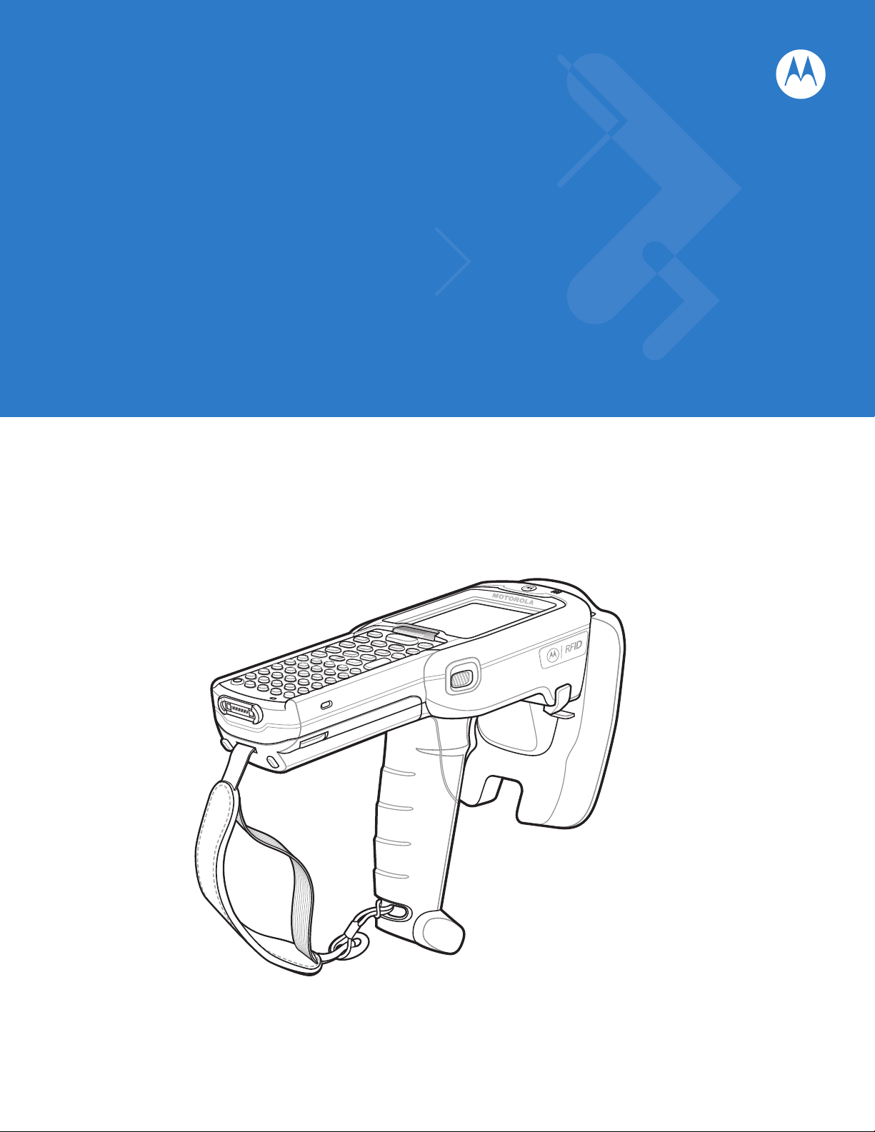
MC319Z RFID Mobile Computer
Integrator Guide
Page 2

Page 3

MC319Z RFID Mobile Computer
Integrator Guide
72E-146158-01
Beta Draft
January 2011
Page 4

ii MC319Z RFID Mobile Computer Integrator Guide
© 2011 Motorola Solutions, Inc. All rights reserved.
No part of this publication may be reproduced or used in any form, or by any electrical or mechanical means,
without permission in writing from Motorola. This includes electronic or mechanical means, such as
photocopying, recording, or information storage and retrieval systems. The material in this manual is subject to
change without notice.
The software is provided strictly on an “as is” basis. All software, including firmware, furnished to the user is on
a licensed basis. Motorola grants to the user a non-transferable and non-exclusive license to use each
software or firmware program delivered hereunder (licensed program). Except as noted below, such license
may not be assigned, sublicensed, or otherwise transferred by the user without prior written consent of
Motorola. No right to copy a licensed program in whole or in part is granted, except as permitted under
copyright law. The user shall not modify, merge, or incorporate any form or portion of a licensed program with
other program material, create a derivative work from a licensed program, or use a licensed program in a
network without written permission from Motorola. The user agrees to maintain Motorola’s copyright notice on
the licensed programs delivered hereunder, and to include the same on any authorized copies it makes, in
whole or in part. The user agrees not to decompile, disassemble, decode, or reverse engineer any licensed
program delivered to the user or any portion thereof.
Motorola reserves the right to make changes to any software or product to improve reliability, function, or
design.
Motorola does not assume any product liability arising out of, or in connection with, the application or use of
any product, circuit, or application described herein.
No license is granted, either expressly or by implication, estoppel, or otherwise under any Motorola, Inc.,
intellectual property rights. An implied license only exists for equipment, circuits, and subsystems contained in
Motorola products.
MOTOROLA, MOTO, MOTOROLA SOLUTIONS and the Stylized M Logo are trademarks or registered
trademarks of Motorola Trademark Holdings, LLC and are used under license. All other trademarks are the
property of their respective owners.
Motorola Solutions, Inc.
One Motorola Plaza
Holtsville, New York 11742-1300
http://www.motorola.com/enterprisemobility
Warranty
For the complete Motorola hardware product warranty statement, go to:
http://www.motorola.com/enterprisemobility/warranty.
Page 5

Revision History
Changes to the original manual are listed below:
Change Date Description
-01 Rev A 1/2011 Initial release
iii
Page 6

iv MC319Z RFID Mobile Computer Integrator Guide
Page 7

Table of Contents
About This Guide
Introduction.................................................................................................................... vii
Configurations................................................................................................................ vii
Chapter Descriptions..................................................................................................... viii
Notational Conventions....................................... ............................ ......................... ...... viii
Related Documents and Software........................ ........................ ....................... .......... ix
Service Information........................................................................................................ ix
Chapter 1: Getting Started
Introduction ................................................................................................................... 1-1
RFID Technology Overview .......................................................................................... 1-1
RFID Components .................................................................................................. 1-2
MC319Z RFID Mobile Computer ...................................... .. .......................................... 1-3
MC319Z RFID Mobile Computer Parts ................................................................... 1-4
MC319Z RFID Mobile Computer LEDs ......................... .......................................... 1-5
Reading Tags ..................... .. ..................................................................... .. .. ............... 1-5
Chapter 2: Updating the Mobile Computer
Introduction ................................................................................................................... 2-1
Updating the Device Image .......................................................................................... 2-1
Downloading an Update Loader Package ........................................... ................... 2-1
Updating Images via ActiveSync ............................................................................ 2-1
Updating Images via AirBEAM ................................................................................ 2-2
Updating the RFID Firmware ................................. ..................................................... .. 2-2
Downloading Firmware Files ..................................................... .............................. 2-2
Updating the Firmware and OEM Data Using the RFID_FLASH Utility .................. 2-3
Chapter 3: LLRP Functionality
Introduction ................................................................................................................... 3-1
LLRP Icons ................................................................................................................... 3-2
LLRP Menu ................................................................................................................... 3-2
Page 8

vi MC319Z RFID Mobile Computer Integrator Guide
Configure Region .................................................................................................... 3-3
Configure LLRP ...................................................................................................... 3-7
Version Infor m a ti o n ...................................................... ... .. ...................................... 3-7
Exit LLRP ............ ............. .. ... ....................................... ... .. ...................................... 3-8
LLRP Registry Entries .................................................................................................. 3-8
Chapter 4: RFID Sample Application [TBD]
[DEMO APPLICATION TBD] ........................................................................................ 4-1
Introduction ................................................................................................................... 4-1
Launching the RFID Sample Application ...................................................................... 4-2
Sample Application Menu Options ................................................................................ 4-3
Configuration Menu Options ......................................... ......................... ................. 4-3
Operations Menu Options ....................................................................................... 4-6
Management Menu Options ....................... ................................. .. .......................... 4-11
About ....................................................................................................................... 4-13
Reading Tags ..................... .. ..................................................................... .. .. ............... 4-14
Chapter 5: Tag Locator
Introduction ................................................................................................................... 5-1
Using Tag Locator ................ .. ............................... .. ............................... ...................... 5-2
Locating Tags Using a .csv File ........................................... ......................................... 5-3
Chapter 6: Troubleshooting
Introduction ................................................................................................................... 6-1
Troubleshooting ............................................................................................................ 6-1
Appendix A: Technical Specifications
Technical Specifications ............................................................................................... A-1
Appendix B: RFID APIs
Index
Page 9

About This Guide
Introduction
This MC319Z RFID Integrator Guide provides the unique set up and operating procedures for the MC319Z RFID
mobile computers. This guide is intended as a supplement to the MC3000 Integrator Guide, p/n 72E-68900-xx.
Procedures common to MC3000 products are addressed in the MC3000 Integrator Guide.
NOTE Screens and windows pictured in this guide are samples and may differ from actual screens.
Configurations
All MC319Z models support the following features:
•
Windows Mobile 6.5 Platform
•
128 MB RAM / 1 GB Flash
•
48-key alphanumeric keypad
•
Color display
•
WLAN 802.11 a/b/g radio
•
Bluetooth
This guide covers the following configurations:
Configuration Country Support Power Data Capture
MC319Z-GL4H24E0W Worldwide 1 W Laser, RFID
MC319Z-GL4H24E0E Europe 0.5 W Laser, RFID
MC319Z-GI4H24E0W Worldwide 1 W Imager, RFID
MC319Z-GI4H24E0E Europe 0.5 W Imager, RFID
Page 10

viii MC319Z RFID Mobile Computer Integrator Guide
Chapter Descriptions
Topics covered in this guide are as follows:
•
Chapter 1, Getting Started provides an overview of RFID technology and components and a description of
the MC319Z RFID mobile computer and features.
•
Chapter 2, Updating the Mobile Computer describes how to update the device image and radio firmware.
•
Chapter 3, LLRP Functionality includes information on configuring the LLRP Server Module and reading
tags.
•
Chapter 4, RFID Sample Application [TBD] provides information on the RFID sample application and how to
use it to assist in custom application development.
•
Chapter 6, Troubleshooting describes MC319Z RFID mobile computer troubleshooting procedures.
•
Appendix A, Technical Specifications includes the technical specifications for the reader.
•
Appendix B, RFID APIs provides a reference for information on supported RFID APIs.
Notational Conventions
The following conventions are used in this document:
•
“Mobile computer” or “reader” refers to the MC319Z RFID mobile computer.
•
Italics are used to highlight the following:
• Chapters and sections in this and related documents
• Dialog box, window, links, software names, and screen names
• Drop-down list, columns and list box names
• Check box and radio button names
• Icons on a screen
•
Bold text is used to highlight the following:
• Dialog box, window and screen names
• Drop-down list and list box names
• Check box and radio button names
• Icons on a screen
• Key names on a keypad
• Button names on a screen
•
Bullets (•) indicate:
• Action items
• Lists of alternatives
• Lists of required steps that are not necessarily sequential.
•
Sequential lists (e.g., those that describe step-by-step procedures) appear as numbered lists.
Page 11

Related Documents and Software
The following documents provide more information about the reader.
•
MC319Z RFID Mobile Computer Quick Start Guide, p/n 72-71347-xx
•
MC319Z RFID Mobile Computer Regulatory Guide, p/n 72-68903-xx
•
MC3000 Mobile Computer User Guide, p/n 72E-68899-xx
•
MC3000 Mobile Computer Integrator Guide, p/n 72E-68900-xx
•
Microsoft Applications for Windows Mobile 6 User Guide, p/n 72E-108299-xx
•
Application Guide for Motorola Enterprise Mobility Devices, p/n 72E-68902-xx
•
Wireless Fusion Enterprise Mobility Suite User Guide for Version 2.55, p/n 72E-107170-01
•
Mobility Services Platform 3.2 User’s Guide, p/n 72E-100158-xx
•
MC319Z RFID Enterprise Mobility Developer Kit
For the latest version of this guide and all guides, go to: http://supportcentral.motorola.com.
About This Guide ix
Service Information
If you have a problem with your equipment, contact Motorola Enterprise Mobility support for your region. Contact
information is available at: http://www.motorola.com/enterprisemobility/contactsupport.
When contacting Enterprise Mobility support, please have the following information available:
•
Serial number of the unit
•
Model number or product name
•
Software type and version number
Motorola responds to calls by e-mail, telephone or fax within the time limits set forth in service agreements.
If your problem cannot be solved by Motorola Enterprise Mobility Support, you may need to return your equipment
for servicing and will be given specific directions. Motorola is not responsible for any damages incurred during
shipment if the approved shipping container is not used. Shipping the units improperly can possibly void the
warranty.
If you purchased your Enterprise Mobility business product from a Motorola business partner, please contact that
business partner for support.
Page 12

x MC319Z RFID Mobile Computer Integrator Guide
Page 13

Chapter 1 Getting Started
Host Computer
Tags
Mobile Computer
Wireless LAN/
BT/ActiveSync
RF Wave a nd
Response
Introduction
This chapter provides an overview of RFID technology and components, and describes the MC319Z RFID mobile
computer and its features.
RFID Technology Overview
RFID (Radio Frequency Identification) is an advanced automatic identification (Auto ID) technology that uses radio
frequency signals to identify tagged items. An RFID tag contains a circuit that can store data. This data may be
pre-encoded or can be encoded in the field. The tags come in a variety of shapes and sizes.
To read a tag the mobile computer sends out radio frequency waves using its integrated antenna. This RF field
powers and charges the tags, which are tuned to receive radio waves. The tags use this power to modulate the
carrier signal. The reader interprets the modulated signal and converts the data to a format for computer storage.
The computer application translates the data into an understandable format.
Figure 1-1
RFID System Elements
Page 14

1 - 2 MC319Z RFID Mobile Computer Integrator Guide
RFID Components
Motorola RFID solutions offer low cost, long read range, and a high read rate. These features provide real time
end-to-end visibility of products and assets in the factory, distribution center, retail outlet, or other facility. The
MC319Z RFID system consists of the following components:
•
Silicon-based RFID tags that attach to retail products, vehicles, trailers, containers, pallets, boxes, etc.
•
An integrated antenna that supports applications such as item level tracking and asset tracking.
•
An embedded radio module that powers and communicates with tags for data capture and provides host
connectivity for data migration.
Tags
Tags contain embedded chips that store unique information. Available in various shapes and sizes, tags, often
called
transponders, receive and respond to data requests. Tags require power to send data.
There are several categories of tags based on the protocol they support, read/write memory, and power options:
•
Active RFID tags are powered by internal light-weight batteries, and also use these batteries to broadcast
radio waves to the reader.
•
Semi-passive RFID tags are also powered by internal light-weight batteries, but draw broadcasting power
from the reader.
•
Passive RFID tags are powered by a reader-generated RF field. These tags are much lighter and less
expensive than active tags, and are typically applied to less expensive goods.
Antenna
Antennas transmit and receive radio frequency signals.
Radio Module
The radio module communicates with the tags and transfers the data to a host computer. It also provides features
such as filtering, CRC check, and tag writing. The MC319Z RFID mobile computer supports standard RFID tags as
described by EPCGlobal
TM
Class 1 Gen2 protocol.
Page 15
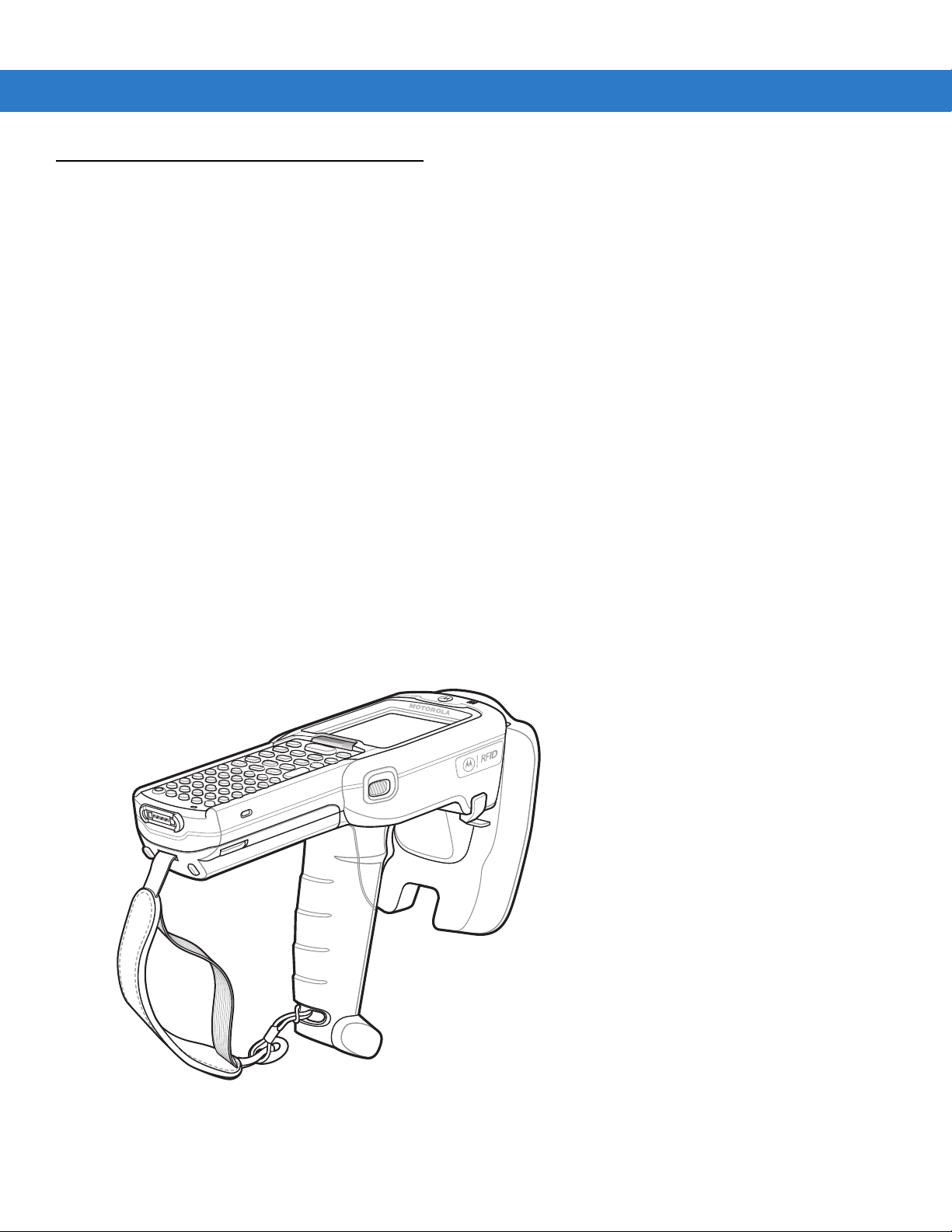
MC319Z RFID Mobile Computer
The Motorola MC319Z RFID mobile computer includes an intelligent C1G2 UHF RFID reader with RFID read
performance that provides real-time, seamless EPC-compliant tags processing. MC319Z RFID mobile computers
are designed for indoor inventory management and asset tracking applications, and can host third-party,
customer-driven embedded applications. Features include:
•
ISO 18000-6C standard (EPC Class 1 Gen 2)
•
Read, write, kill, lock, block write/block erase, permalock, and perma tag functionality
•
48-key alphanumeric keypad
•
3” color display
•
Orientation-insensitive integrated external antenna
•
Laser-based bar code reader - reads 1D bar codes
•
Windows® Mobile 6.1
•
WLAN 802.11 a/b/g wireless connectivity
Getting Started 1 - 3
•
Application-specific setup for ease of installation
•
Low Level Reader Protocol (LLRP)
•
Sample application and support for custom or third-party applications
•
RFID API support
•
Event and tag management support
Figure 1-2
MC319Z RFID Mobile Computer
Page 16
1 - 4 MC319Z RFID Mobile Computer Integrator Guide
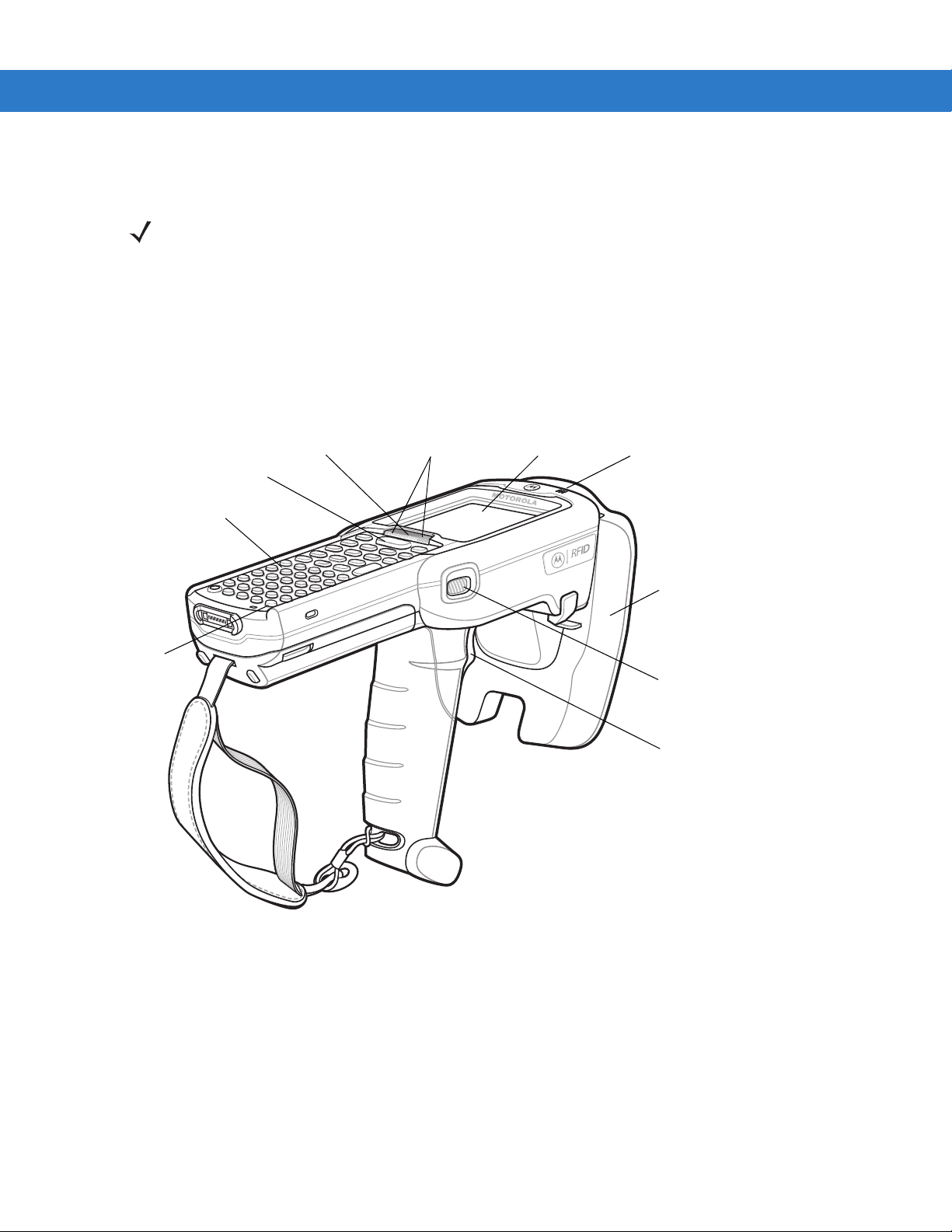
Keypad
RFID Module
Display
Power
Scan Button
Beeper
Trigger
Scan LED
Indicators
(red/green)
Charge LED
Indicator
(amber)
Scan LED Indica tor
(red/green)
The MC319Z RFID mobile computer provides a wide range of features that enable implementation of complete,
high-performance, intelligent RFID solutions.
NOTE The MC319Z RFID mobile computer supports a 2x battery only; do not use a 1x battery.
The Four-Slot Cradle does not accommodate the MC319Z RFID mobile computer.
Due to component tolerances, some users may experience undesired behavior when using battery part number
55-0601 1 2-xx. If the un it turns of f wi thout p roper warn ing me ssag es duri ng hea vy us e, use battery 55-00 2152-x x
(p/n 82-127909-xx).
MC319Z RFID Mobile Computer Parts
Figure 1-3
MC319Z RFID Mobile Computer Parts
Page 17

MC319Z RFID Mobile Computer LEDs
The mobile computer LEDs indicate charging and reader status as described in Table 1-1.
Getting Started 1 - 5
Table 1-1
Charging Indicators
Off Mobile computer not placed correctly in the cradle; cable not connected correctly;
Fast Blinking Amber Error in charging; check placement of mobile computer.
Slow Blinking Amber Mobile computer is charging.
Solid Amber Charging complete.
Reading Tags
To read RFID tags:
1. Remove the MC319Z from AC power and ensure the LLRP icon is green.
NOTE When connected to power, the mobile computer cannot read RFID tags.
LED Status Indicators
LED Indication
charger is not powered.
Note: When the battery is initially inserted in the mobile computer, the amber LED
flashes once if the battery power is low or the battery is not fully inserted.
2. Use an RFID reader application to enable tag reading. For a sample application, browse to the MC319Z
Application directory and select RFIDSample3Plus.exe. See Chapter 4, RFID Sample Application [TBD].
3. Aim the mobile computer at the tag, oriented horizontally or vertically depending on the tag orientation. The
distance between the tag and the antenna is the approximate read range.
4. Press the trigger or tap the on-screen Read command within the application to interrogate all RFID tags within
the radio frequency (RF) field of view and capture data from each new tag found. Release the trigger or tap the
Stop Read command to stop interrogating tags.
Page 18

1 - 6 MC319Z RFID Mobile Computer Integrator Guide
Page 19

Chapter 2 Updating the Mobile Computer
Introduction
This chapter describes how to update the device image and radio firmware.
Updating the Device Image
Windows Mobile contains an Image Update feature that updates all operating system components. Motorola
distributes all updates as update packages on the Support Central Web Site
http://www.motorola.com/enterprisemobility/support
the operating system.
To update an operating system component, copy the update package to the mobile computer using ActiveSync,
AirBEAM, or MSP.
Downloading an Update Loader Package
. These packages contain either partial or complete updates for
1. Download the appropriate update loader package from the Motorola Support Central web site
http://www.motorola.com/enterprisemobility/support
2. Locate the update loader package file on the host computer and un-compress the file into a separate directory:
•
30XXw61RFIDSCxxxxx.zip for updating via ActiveSync
•
30XXw61RFIDABxxxxx.zip for updating via AirBEAM
to a host computer.
Updating Images via ActiveSync
To install an update loader package using ActiveSync:
1. Insert the mobile computer into the cradle and connect the cradle to AC power.
2. Connect the mobile computer to the host computer using ActiveSync.
3. In ActiveSync on the host computer, open Explorer for the mobile computer.
4. Copy the contents of 30XXw61MenUPR10903\UpdateLoader (the files only, not the folder) into the \Storage Card
folder on the mobile computer.
Page 20

2 - 2 MC319Z RFID Mobile Computer Integrator Guide
5. On the mobile computer, navigate to the \Storage Card folder and tap the program STARTUPDLDR.EXE. The
update takes approximately 10 minutes. Do not remove AC power during this time.
6. Copy the contents of 30XXw61RFIDPkgXXXX (the files only, not the folder) into the \Storage Card folder on the
mobile computer.
7. Remove the mobile computer from the cradle or AC power if fully charged.
8. On the mobile computer, navigate to the \Storage Card folder and tap the program RFIDSetup.exe
The device boots after the installation. Note that the RFID LLRP application disconnects when the mobile computer
is charging, and re-connects when the mobile computer is removed from AC power.
Updating Images via AirBEAM
Install the AirBEAM package files within 30XXw61RFIDABxxxxx.zip in sequence:
1. 30XXw61MenUPRXXXXX.apf
2. 30XXw61RFIDPkgXXXX.apf
30XXw61RFIDPkgXXXX.apf
executes silently and the mobile computer boots after installation, which takes
approximately 7-10 seconds. Refer to the MC3000 Integrator Guide for more information on AirBEAM.
NOTE If you exit LLRP via the icon menu, to restart it use File Explorer on the mobile computer to navigate to
\Application\LLRP\ and tap the MobileLLRP.exe application.
Updating the RFID Firmware
Use the RFID_FLASH utility to update the firmware for the RFID radio. Motorola distributes the firmware and OEM
update files on the Support Central Web Site http://www.motorola.com/enterprisemobility/support
CAUTION When upgrading the firmware, Motorola recommends placing the mobile computer in a cradle with
external AC power connected. An interruption in the firmware update, e.g., due to loss of power, can
render the RFID module inoperable.
Downloading Firmware Files
1. Download the firmware update files from the Motorola Support Central web site
http://www.motorola.com/enterprisemobility/support
2. Connect the mobile computer to the host computer using ActiveSync.
3. In ActiveSync on the host computer, open Explorer for the mobile computer.
.
to a host computer.
4. Copy the firmware file and the OEM data file into the \Application folder on the mobile computer.
Page 21

Updating the Mobile Computer 2 - 3
Updating the Firmware and OEM Data Using the RFID_FLASH Utility
1. On the mobile computer, navigate to the \Application folder and tap the program RFID_FLASH.
Figure 2-1
2. Tap Browse in the Firmware section of the window.
3. In the Open window, select the firmware file.
Figure 2-2
RFID_FLASH Window
Selecting the Firmware File
Page 22

2 - 4 MC319Z RFID Mobile Computer Integrator Guide
4. Tap Update Firmware and wait until the progress bar completes.
Figure 2-3
5. Tap Browse in the OEM section of the window.
6. In the Open window, select the OEM data file.
Figure 2-4
7. Tap Update OEM to start the update. Wait until the progress bar completes and OEM LOADED appears.
Starting Firmware Update
NOTE When updating the firmware dat a file, the mo bile comp uter display s a progress ba r . This bar ma y indicate
some progress, then move quickly to complete.
Selecting the OEM File
Figure 2-5
Updating OEM
Page 23

Chapter 3 LLRP Functionality
LLRP Server Icon
Introduction
Low Level Reader Protocol (LLRP) is an RFID server application that runs in the background on the mobile
computer. The LS icon in the system tray represents LLRP. This chapter includes information on using and
configuring the LLRP Server Module.
Figure 3-1
LLRP Icon
Page 24

3 - 2 MC319Z RFID Mobile Computer Integrator Guide
LLRP Icons
The LLRP icon indicates radio status as described in Table 3-1.
Table 3-1
Icon Icon State Indication
LLRP Menu
Tap the LLRP icon to display the option menu shown in Figure 3-2.
LLRP Icon Indicators
Green LLRP is enabled.
Crossed icon No radio connection or radio disconnected.
Yellow R adio is readin g at a reduced power level than set due to a cold or
degraded battery.
Red Radio is unable to read, even at a reduced power level, due to a battery
condition.
Figure 3-2
LLRP Menu
Page 25

Configure Region
Upon Startup
After upgrading the mobile computer, the following window appears on startup.
LLRP Functionality 3 - 3
Figure 3-3
1. Tap ok. When no country is selected, the Configure regions settings window appears.
Figure 3-4
Country Not Set Window
Configure Region Settings Window
Page 26

3 - 4 MC319Z RFID Mobile Computer Integrator Guide
2. Select the region of operation and communication standard as allowed by the regulatory standards of that
country/region from the drop-down menus. The following warning message appears.
Figure 3-5
3. Tap Yes to confirm. A window appears indicating success.
Figure 3-6
Region Selection Warning Message
Region Selection Success Window
Page 27

After Startup
If not done at startup, set the regulatory region using the LLRP icon menu:
1. Tap the LLRP icon, then tap Configure Region.
LLRP Functionality 3 - 5
Figure 3-7
2. Select a region from the Region of Operation drop-down in the following window.
Figure 3-8
Configure Region Optio n
Configure Region Settings Window
Page 28

3 - 6 MC319Z RFID Mobile Computer Integrator Guide
3. Tap Yes on the warning window that appears. A confirmation window appears.
Figure 3-9
4. Tap ok.
Region Selection Success Window
Page 29

Configure LLRP
LLRP is in Server Mode by default. To configure LLRP to operate in Client Mode:
1. Tap the LLRP icon, then tap Configure LLRP.
LLRP Functionality 3 - 7
Figure 3-10
2. Select the Client Mode check box.
3. In the LLRP Port field, enter the port number on which the server waits for the LLRP client to communicate. The
LLRP Configuration Window
default is 5084.
4. In the Server IP field, enter the server IP for the remote host to which LLRP communicates as a client.
5. Tap Apply.
6. Tap ok to close the window.
Version Information
To view software version information for the LLRP application, tap the LLRP icon, then tap Version Info.
Figure 3-11
LLRP Versions Window
This window displays the LLRP server application version, RFID library version, radio firmware version, and radio
OEM data version.
NOTE The version information in Figure 3-11 may differ from the information on the actual mobile computer
screen. Also, downloading data using LLRP scripts or the RFID_FLASH application updates the version
information.
Page 30

3 - 8 MC319Z RFID Mobile Computer Integrator Guide
Exit LLRP
Tap the LLRP icon, then tap Exit to close the LLRP application.
To restart LLRP after exiting, use
executable (MobileLLRP.exe).
LLRP Registry Entries
RFID (LLRP) does not run when the MC319Z is charging. Developers who require using the cradle with RFID
enabled can select Developer Mode by modifying a registry entry.
•
User Mode - In this default mode, placing the mobile computer in the cradle (with charging on) disables LLRP
and the LLRP icon indicates that it is disconnected. Placing the mobile computer on AC power charges the
device and disables LLRP. Removing AC power reconnects LLRP.
•
Developer Mode - Selecting Developer Mode disables charging and the developer can place the mobile
computer in the cradle for debugging and development. The device remains in Developer Mode regardless of
whether it is charging until re-enabling User Mode.
To select Developer Mode via registry:
1. Edit the file params.reg in the \Application folder. To do this, copy the file to the PC, or use a word editor on the
mobile computer.
2. Set the DevMode registry entry value to 1:
[HKEY_LOCAL_MACHINE\SOFTWARE\Symbol\RFID\LLRP]
"DevMode"=dword:00000001
File Explorer to browse to the \Application\LLRP folder and tap the LLRP
3. Tap on the modified file and select Yes to merge the registry.
4. Warm boot the device by holding down the 7, 9, and Power keys.
5. Restart LLRP (if it is not already running).
To change back to user mode, repeat this procedure, setting
LLRP checks AC power every five seconds and takes the appropriate action based on whether or not it is in User
Mode.
DevMode to 0.
Page 31

Chapter 4 RFID Sample Application [TBD]
[DEMO APPLICATION TBD]
Introduction
Application developers can use the RFID sample application RFIDSample3Plus.exe for an overview of how the
application works and to assist in custom application development.
The mobile computer can read, write, lock, kill, and program Gen2 tags. Each tag contains the EPC number (64 or
96 bits), CRC, and kill code. The mobile computer can also collect data by decoding in-range EPC Gen2 RFID
tags.
Initiating the read command within the sample application causes the mobile computer to interrogate all RFID tags
within the radio frequency (RF) field of view. The reader captures data from each new tag and adds it to the list box
in the
EPC ID window. Select Stop Read to stop interrogating tags.
Page 32

4 - 2 MC319Z RFID Mobile Computer Integrator Guide
Launching the RFID Sample Application
Remove the mobile computer from AC power and enable LLRP, then use File Explorer on the mobile computer to
navigate to the
Application folder. Select RFIDSample3Plus.exe to start the sample application.
Figure 4-1
•
•
•
•
RFID Sample Application Window
NOTE The version numbers displayed in this window are examples. Actual version numbers are based on the
versions of the files on the device.
Tap Menu to select the menu options. See Sample Application Menu Options on page 4-3.
Tap the Start Read button to initiate the tag read. Tap Stop Read to terminate tag reading. See Reading Tags
on page 4-14.
Use the Mem Bank drop-down to select a tag memory bank to read. The default memory bank is EPC
(
None). Other options are TID, Reserved, and User.
Tap the note icon to generate an audio notification (beep) when the reader finds a new tag in the field of view.
Page 33

Sample Application Menu Options
The Menu options include:
•
Configuration options
•
Operations options
•
Reader management options
•
About
RFID Sample Application [TBD] 4 - 3
Figure 4-2
Sample Application Menu
Configuration Menu Options
The Config menu includes the following options :
•
Connection information
•
Configuration options
•
Capabilities
•
Reset Factory defaults
•
Exit
Figure 4-3
Configuration Menu
Page 34

4 - 4 MC319Z RFID Mobile Computer Integrator Guide
Connection
Select Config > Connection to display the reader IP and port number.
Figure 4-4
Select
Connection Window
Disconnect to disconnect the reader.
Antenna
Select Config > Configuration > Antenna to configure the antenna.
Figure 4-5
This window includes the following fields:
Antenna Configuration Window
•
Antenna - Selecting an antenna ID updates the configuration values in the other fields.
•
Receive Sensitivity(dB) - Lists the reader-supported values for the selected antenna.
•
Transmit Power - Lists the reader-supported values for the selected antenna.
•
Hop Index - Updates the Hop Frequency list with its corresponding frequencies.
•
Apply - Select to apply the configuration changes.
Page 35

RFID Sample Application [TBD] 4 - 5
Singulation
Select Config > Configuration > Singulation to set the options for identifying an individual tag in a multiple-tag
environment.
Figure 4-6
This window includes the following fields:
•
•
•
•
•
•
•
Singulation Window
Antenna - Selecting an antenna ID updates the configuration values in the other fields.
Session - The session number for the inventory operation.
Tag Transmit Time - The time in milliseconds that the tag typically remains in the RF field of the antenna.
Tag Population - The approximate tag population in the RF field of the antenna.
Inventory State - Select a tag of state A or B.
SL Flag
Apply - Select to apply the configuration changes.
Capabilities
Select Config > Capabilities to retrieve the capabilities of the connected reader.
Figure 4-7
Select
OK to close the window.
Capabilities Window
Page 36

4 - 6 MC319Z RFID Mobile Computer Integrator Guide
Reset Factory Defaults
Select Config > Reset Factory Defaults to restore the default reader configuration.
Operations Menu Options
The Operations menu options include:
•
Tag Storage Settings
•
Filter options
•
Access options
•
Trigger settings
•
Antenna information
Figure 4-8
Operations Menu
Tag Storage Settings
Select Operations > Tag Storage Settings to change the tag storage settings.
Figure 4-9
This window includes the following fields:
•
Tag Storage Window
Max tag count - The maximum number of tags to store in the DLL.
•
Max tag ID length - The maximum tag length.
Page 37

RFID Sample Application [TBD] 4 - 7
•
Max size of memory bank - Storage to allocate for the memory bank's data.
•
Apply - Select to apply the configuration changes.
Filter Settings
Use the sample application’s filter settings to set filters for tag reading. The application supports up to two pre-filters
and two post-filters. By default, the window displays the latest filter information. Add or delete the filter by selecting
Use Filter.
Pre-Filter
To select pre-filter settings, select Operations > Filter > Pre-Filter.
Figure 4-10
This window includes the following fields:
•
•
•
•
•
Pre-Filter Window
Antenna - Selecting an antenna ID updates the configuration values in the other fields.
Memory Bank - Select the memory bank.
Offset - The first (msb) bit location of the specified memory bank against which to compare the tag mask.
Tag Mask - The pattern against which to compare the specified memory bank.
Filter action - Select the required filter action. For more information, refer the Gen2 specification available at
http://www.epcglobalinc.org/standards/.
Page 38

4 - 8 MC319Z RFID Mobile Computer Integrator Guide
Post-Filter
To select post-filter settings, select Operations > Filter > Post-Filter.
Figure 4-11
This window includes the following fields:
•
•
•
•
•
Post Filter Window
Match Pattern - Select the tag pattern to match (A, B, both, or neither).
Memory Bank - Select the memory bank.
Offset - The first (msb) bit location of the specified memory bank against which to compare the tag mask.
Bank Data
Tag Mask - The pattern against which to compare the specified memory bank.
Access Filter
To select filter settings to apply to tags, select Operations > Filter > Access Filter.
Figure 4-12
See Post-Filter for descriptions of the window fields.
Post Filter Window
Page 39

RFID Sample Application [TBD] 4 - 9
Access
Select Operations > Access to select from a menu of access parameters to set for tags, or tap and hold a tag in the
list to open a context menu with similar options in order to set operation parameters for that tag.
Figure 4-13
Access and Context Menus
Selecting an option from the context menu applies the operation to the single tag selected. Selecting an option
from the
Select an option from the
Figure 4-14
Windows are similar to the
Block Erase. Set options as required in the various parameter windows. Not all windows include all options.
Access menu updates the tag data for multiple tags in the main window.
Access or context menu to set access parameters and the access filter.
Read and Access Filter Windows
Read window in Figure 4-14 for the menu options Write, Lock, Kill, Block Write, and
•
Tag ID - The nam e of the selected tag.
•
Password - Set a password before performing any access operation (except Kill).
•
Memory Bank - Select the memory bank. Options are:
• Reserved
• EPC
• TID
• User
•
Offset - Offset of the first word to read from the selected memory bank.
Page 40

4 - 10 MC319Z RFID Mobile Computer Integrator Guide
•
Length - Tag/data length.
•
Writ e Data - The data to write to the selected tag (Write window only).
•
Lock Privilege - Access options for the selected tag (Write window only):
• None - The can not change the lock privilege of the particular memory bank.
• Read_Write - The user can read and write to the tag.
• Perma_Lock - Permanent lock.
• Perma_Unlock - Permanent unlock.
• Unlock - The user can unlock the tag for writing.
•
Access Filter - Select this tab to set access filter parameters. See Post-Filter on page 4-8 for more
information.
Triggers
Select Operations > T riggers... to set start and stop triggers. Selecting the type of trigger from the Trigger drop-down
menu updates the window with that trigger’s applicable parameters.
Figure 4-15
Triggers Window
Antenna Information
Select Operations > Antenna Info to select the antennas to use.
Figure 4-16
Antenna Information Window
Page 41

RFID Sample Application [TBD] 4 - 11
Management Menu Options
The Management menu provides access to reader management functionality such as updating firmware, selecting
an antenna mode, and rebooting. The
•
Login and Logout options
•
Reboot option
•
OEM Update option
•
Software/Firmware Update option
Management menu options include:
Figure 4-17
Management Menu
Login/Logout Settings
The Reader Management functionality requires login authentication. Select Mgmt > Login/Logout... to log in or out
of this functionality.
Figure 4-18
This window includes the following fields:
•
Login Window
Reader Type - MC indicates the MC319Z.
•
User name - Enter the user name used to gain access to reader management functionality.
•
Password - Enter the password used to gain access to reader management functionality.
•
IP - IP address of the host. For MC319Z, the default is 127.0.0.1 or localhost.
Page 42

4 - 12 MC319Z RFID Mobile Computer Integrator Guide
Reboot Settings
This feature is not supported by handheld readers.
OEM Update
Select Mgmt > OEM Update to update the reader configuration file.
Figure 4-19
Enter the
OEM Update Window
Path Name indicating the location and name of the configuration file, and select Start Update.
Software/Firmware Update
Select Mgmt > Software/Firmware Update to update the reader firmware software.
Figure 4-20
Enter the
OEM Update Window
Path Name indicating the location and name of the update file, and select Start Update.
Page 43

About
The About window displays the sample application version information
RFID Sample Application [TBD] 4 - 13
Figure 4-21
NOTE The version numbers displayed in this window are examples. Actual version numbers are based on the
About Window
versions of the files on the device.
Page 44

4 - 14 MC319Z RFID Mobile Computer Integrator Guide
Reading Tags
To use the sample application to read tags:
1. Aim the mobile computer at the tag in any orientation (horizontally or vertically). The distance between the tag
and the antenna is the approximate read range.
Figure 4-22
2. Tap Start Read to interrogate all RFID tags within the radio frequency (RF) field of view, and capture data from
each new tag found.
Figure 4-23
The sample application lists the following information for each tag read:
•
•
RFID Tag Read
RFID Tag List
EPC ID - The data content of the tag.
RSSI - Received Signal Strength for the tag.
•
Count - The number of times the mobile computer read the tag.
•
Data Memory Bank - The memory bank data if you selected Reserved, TID, User, or EPC with offset.
•
MB - The selected memory bank (TID, RSVD, USER or EPC).
Stop Read to stop interrogating tags.
Tap
Page 45

Chapter 5 Tag Locator
Introduction
Use Tag Locater to detect the location of a tag. By providing the TagID of an item, this application can find the
relative position of the tag with respect to the mobile computer. Move the mobile computer back and forth to obtain
the location of the tag as indicated by the beep frequency and a vertical progress bar showing the relative position
of the tag.
The Tag Locater application requires the following components/DLLs on the device:
•
RFIDAPI32.dll (Version 5.1.15 or higher)
•
Symbol.RFID3.Device.dll (Assembly version 1.1.0.1, File version 1.1.0.7 or higher)
•
Symbol.Audio.dll
•
Symbol.dll
•
Symbol.Notification.dll
•
Symbol.StandardForms.dll
Page 46

5 - 2 MC319Z RFID Mobile Computer Integrator Guide
Using Tag Locator
To use the Tag Locator application:
1. Tap TagLocator in the Application folder on the mobile computer to open the Tag Locater application.
Figure 5-1
2. Enter the tag ID in one of three ways:
•
•
•
Tag Locator
Type the tag ID in the TagID text box, then select Locate or press and hold the trigger.
Perform a search operation by selecting the Search Tags button or by pressing and holding the trigger.
Select the Import Tags button to import a list of saved tags from a .csv file. See Locating Tags Using a .csv
File on page 5-3.
Page 47

Locating Tags Using a .csv File
1. Select the Import Tags button to import a list of saved tags from a .csv file. The following window appears.
Tag Locator 5 - 3
Figure 5-2
2. Select the desired .csv file to import the tags to the list.
Figure 5-3
3. Select a tag from the list to search.
Opening a .csv File
Tag List
Page 48

5 - 4 MC319Z RFID Mobile Computer Integrator Guide
4. Select the Locate button or press and hold the trigger. Move the mobile computer in all directions to get the
relative position of the tag, indicated by a beep, the vertical progress bar, or both.
Figure 5-4
Use the
Figure 5-5
Options menu to turn the beeper on and off and to display data in ASCII or hexadecimal format.
Tag Search
Options Menu
Page 49

Chapter 6 Troubleshooting
Introduction
Table 6-1 on page 6-1 provides troubleshootin g inform atio n.
Troubleshooting
Table 6-1
Mobile computer does not turn on. Lithium-ion battery not
Rechargeable lithium-ion battery
did not charge.
Mobile computer turns off without
proper warning messages during
heavy use.
Troubleshooting
Problem Possible Causes Possible Solutions
charged.
Lithium-ion battery not
installed properly.
System crash. Perform a warm boot. If the RFID reader still does
Battery failed. Replace battery. If the mobile computer still does
Mobile computer removed
from cradle while battery
was charging.
Due to component
tolerances, this can occur
when using battery part
number 55-060112-xx.
Charge or replace the lithium-ion battery.
Ensure battery is installed properly. Refer to the
MC3000 Mobile Computer Integrator Guide.
not turn on, perform a cold boot. Refer to the
MC3000 Mobile Computer Integrator Guide.
not operate, try a warm boot, then a cold boot.
Refer to the MC 3000 Mobile Computer Integrator
Guide.
Insert mobile computer in cradle and begin
charging. The lithium-ion battery requires less than
four hours to recharge fully.
Use battery 55-002152-xx (p/n 82-127909-xx).
No sound. Volume setting is low or
turned off.
Increase the volume setting.
Page 50

6 - 2 MC319Z RFID Mobile Computer Integrator Guide
Table 6-1
Troubleshooting (Continued)
Problem Possible Causes Possible Solutions
Tapping the window buttons or
icons does not activate the
LCD screen not aligned
correctly.
corresponding feature.
Battery is not inserted
properly.
A message appears stating that the
mobile computer memory is full.
Too many files stored on the
mobile computer.
Too many applications
installed on the mobile
computer.
Reader is not reading tags. The tag is out of its read
range.
Tags are damaged.
Tags are not EPCgen2.
Read application is not
loaded.
Reader is not reading tags and the
LLRP icon is red.
The battery is cold or
degraded.
Re-calibrate the screen.
Insert the battery properly. Refer to the MC3000
Mobile Computer Integrator Guide.
Delete unused memos and records. Save these
records on the host computer.
If additional applications have been installed on
the RFID reader, remove them to recover memory.
Tap
Start
>
Settings
Programs
icon.
Move the tag into the read range. See
Tags on page 1-5
.
>
System
tab >
Remove
Reading
Use tags of good quality .
Use EPCgen2 tags.
Verify that the unit is loaded with a read
application.
Recharge or replace the battery. If the problem still
exists, exit and restart LLRP.
NOTE If problems still occur, contact the distributor or call the local contact. See page ix for contact information.
Page 51

Appendix A Technical Specifications
Technical Specifications
The following tables summarize the RFID reader intended operating environment and technical hardware
specifications.
Table A-1
Physical and Environmental Characteristics
Dimensions 9.1 in. L x 3.6 in. W x 7.6 in. H
Weight 23 oz. / 650 g (includes battery, RFID, scanner, and radio)
Keypad 48 key
Display 3 in. 320 x 320 pixel color
Battery Extended capacity (2X) battery pack
Performance Characteristics
CPU
Operating System Microsoft Windows Mobile 6.1
Memory (RAM/ROM) 128 MB RAM/1 GB Flash
Application Development SMDKs available through the Support Web Site
Data Capture Options Laser engine reads 1D symbologies with intuitive laser aiming.
Technical Specif ic at ion s
Item MC319Z RFID
23.1 cm L x 9.1 cm H x 19.3 cm H
Terminal Emulation (5250, 3270, VT)
®
XScale® Bulverde PXA270 processor at 624MHz
Intel
RFID reader reads Gen2 tags.
Page 52

A - 2 MC319Z RFID Mobile Computer Integrator Guide
Table A-1
Technical Specific at ion s (Co nti nue d)
Item MC319Z RFID
Laser Decode Capability Code 39 Code 128 Code 93
Codabar Code 11 Discrete 2 of 5
Interleaved 2 of 5 EAN-8 EAN-13
MSI UPCA UPCE
UPC/EAN supplementals Coupon Code Trioptic 39
Webcode RSS-14 RSS Limited
RSS Expanded EAN-128 TLC39
Composite Code PDF417 Micro PDF417
Macro PDF417 MSI Plessey Maxi Code
Data Matrix US Planet UK 4-State
Australian 4-State Canadian 4-St ate Japanese 4-S t ate
Dutch Kix Aztec USPS 4-State(US4CB)
MicroQR
User Environment
Operating Temperature -4°F to 122°F (-20°C to 50°C)
Battery Charging
32° to 104° F (0° to 40° C) ambient temperature range
Temperature
Storage Temperature -25°F to 160°F (-40°C to 70°C)
Humidity 0% to 95% non condensing
Drop Specification Multiple 6 ft. (1.8m) drops to concrete across operating temperature range
Tumble 2,000 one-meter tumbles at room temperature (4,000 hits)
Environmental Sealing IP64
ESD +/-15kVdc air discharge
+/-8kVdc direct discharge
+/-8kVdc indirect discharge
RFID
Standards Supported EPC Generation 2 UHF
Nominal read range
1
10 ft./3.04 m with the RFX6000 4x4 tag optimally oriented.
Field Half read range beam width: +/- 80 degrees (with tags optimally oriented).
Antenna Integrated, circularly polarized, 1.5 dB effective linear gain per axis (nominal);
Antenna port for future support of optional external antenna.
Frequency Range 902-928 MHz
Output power 1W conducted (1.4W EIRP with integrated antenna)
Page 53

Technical Specifications A - 3
Table A-1
Technical Specific at ion s (Co nti nue d)
Item MC319Z RFID
Wireless Data Communications
WLAN 802.11a/b/g
Output Power 100mW U.S. and International
Data Rate 802.11a: 54Mb per second
802.11b: 11Mb per second
802.11g: 54Mb per second
Antenna Internal
Frequency Range: 802.11a: 5 GHz; country-dependent
802.11b: 2.4 GHz; country-dependent
802.11g: 2.4 GHz; country-dependent
Bluetooth
Bluetooth
®
Version 1.2 with BTExplorer™ (manager) inc luded
Peripherals and Accessories
Cradles Single-slot available
Printers Supports extensive line of Symbol approved printers, cables and accessories
Charger 4-Slot universal battery charger
Other Accessories Cable Adapter Module; Magnetic Stripe Reader; Modem; Full set of holsters
In accordance with the SymbolPlus partner program
Page 54

A - 4 MC319Z RFID Mobile Computer Integrator Guide
Page 55

Appendix B RFID APIs
RFID APIs are available in C and .NET. For information on supported RFID APIs, refer to the Enterprise Mobility
Developer Kit (EMDK), available at http://supportcentral.motorola.com
For C, refer to the EMDK for C v2.1 or later. For .Net, refer to the EMDK for .NET v2.2 or later.
Page 56

B - 2 MC319Z RFID Mobile Computer Integrator Guide
Page 57

Index
A
activesync . . . . . . . . . . . . . . . . . . . . . . . . . . . . . . . . . 2-1
airbeam . . . . . . . . . . . . . . . . . . . . . . . . . . . . . . . . . . . 2-2
antenna . . . . . . . . . . . . . . . . . . . . . . . . . . . . . . . .1-2, 1-3
configuring . . . . . . . . . . . . . . . . . . . . . . . . . . . . . 4-4
information . . . . . . . . . . . . . . . . . . . . . . . . . . . . 4-10
APIs . . . . . . . . . . . . . . . . . . . . . . . . . . . . . . . . . . . . . . B-1
B
battery . . . . . . . . . . . . . . . . . . . . . . . . . . . . . . . . 6-1, A-1
battery charging temperature . . . . . . . . . . . . . . . . . . A-2
C
charge LED indicator . . . . . . . . . . . . . . . . . . . . . . . . . 1-4
configuration . . . . . . . . . . . . . . . . . . . . . . . . . . . . . . . . vii
configuring LLRP . . . . . . . . . . . . . . . . . . . . . . . . . . . . 3-7
region . . . . . . . . . . . . . . . . . . . . . . . . . . . . . . . . . 3-3
connection
ports . . . . . . . . . . . . . . . . . . . . . . . . . . . . . . . . . . 1-4
conventions
notational . . . . . . . . . . . . . . . . . . . . . . . . . . . . . . .viii
CPU . . . . . . . . . . . . . . . . . . . . . . . . . . . . . . . . . . . . . . A-1
D
data capture . . . . . . . . . . . . . . . . . . . . . . . . . . . . . vii, A-1
demo . . . . . . . . . . . . . . . . . . . . . . . . . . . . . . . . . . . . . 4-1
access parameters . . . . . . . . . . . . . . . . . . . . . . . 4-9
antenna . . . . . . . . . . . . . . . . . . . . . . . . . . . .4-4, 4-10
configuration . . . . . . . . . . . . . . . . . . . . . . . . . . . . 4-3
connection . . . . . . . . . . . . . . . . . . . . . . . . . . . . . . 4-4
filtering . . . . . . . . . . . . . . . . . . . . . . . . . . . . . . . . 4-7
firmware update . . . . . . . . . . . . . . . . . . . . . . . . 4-12
launching . . . . . . . . . . . . . . . . . . . . . . . . . . . . . . . 4-2
management . . . . . . . . . . . . . . . . . . . . . . . . . . . 4-11
menu . . . . . . . . . . . . . . . . . . . . . . . . . . . . . . . . . . 4-3
OEM update . . . . . . . . . . . . . . . . . . . . . . . . . . . 4-12
operations . . . . . . . . . . . . . . . . . . . . . . . . . . . . . . 4-6
reader capabilities . . . . . . . . . . . . . . . . . . . . . . . 4-5
rebooting . . . . . . . . . . . . . . . . . . . . . . . . . . . . . . 4-12
singulation . . . . . . . . . . . . . . . . . . . . . . . . . . . . . 4-5
tag storage . . . . . . . . . . . . . . . . . . . . . . . . . . . . . 4-6
triggers . . . . . . . . . . . . . . . . . . . . . . . . . . . . . . . 4-10
dimensions . . . . . . . . . . . . . . . . . . . . . . . . . . . . . . . . A-1
display . . . . . . . . . . . . . . . . . . . . . . . . . . . . . . . . . . . . A-1
drop specification . . . . . . . . . . . . . . . . . . . . . . . . . . . A-2
F
filtering . . . . . . . . . . . . . . . . . . . . . . . . . . . . . . . . . . . . 4-7
firmware update . . . . . . . . . . . . . . . . . . . . . . . .2-2, 4-12
H
humidity . . . . . . . . . . . . . . . . . . . . . . . . . . . . . . . . . . . A-2
I
icons
LLRP . . . . . . . . . . . . . . . . . . . . . . . . . . . . . . . . . . 3-2
image update . . . . . . . . . . . . . . . . . . . . . . . . . . . . . . 2-1
activesync . . . . . . . . . . . . . . . . . . . . . . . . . . . . . . 2-1
airbeam . . . . . . . . . . . . . . . . . . . . . . . . . . . . . . . . 2-2
update loader . . . . . . . . . . . . . . . . . . . . . . . . . . . 2-1
K
keypad . . . . . . . . . . . . . . . . . . . . . . . . . . . . . . . . . .vii, A-1
Page 58

Index - 2 MC319Z RFID Mobile Computer Integrator Guide
L
LEDs . . . . . . . . . . . . . . . . . . . . . . . . . . . . . . . . . . . . . 1-5
LLRP . . . . . . . . . . . . . . . . . . . . . . . . . . . . . . . . . . . . . 3-1
client mode . . . . . . . . . . . . . . . . . . . . . . . . . . . . . 3-7
configuring . . . . . . . . . . . . . . . . . . . . . . . . . . . . . 3-7
configuring region . . . . . . . . . . . . . . . . . . . . . . . . 3-3
developer mode . . . . . . . . . . . . . . . . . . . . . . . . . 3-8
exiting . . . . . . . . . . . . . . . . . . . . . . . . . . . . . . . . . 3-8
icons . . . . . . . . . . . . . . . . . . . . . . . . . . . . . . . . . . 3-2
menu . . . . . . . . . . . . . . . . . . . . . . . . . . . . . . . . . . 3-2
registry entries . . . . . . . . . . . . . . . . . . . . . . . . . . 3-8
server mode . . . . . . . . . . . . . . . . . . . . . . . . . . . . 3-7
user mode . . . . . . . . . . . . . . . . . . . . . . . . . . . . . . 3-8
version information . . . . . . . . . . . . . . . . . . . . . . . 3-7
locating tags . . . . . . . . . . . . . . . . . . . . . . . . . . . . . . . 5-1
M
memory . . . . . . . . . . . . . . . . . . . . . . . . . . . . . . . . . . . A-1
O
OEM update . . . . . . . . . . . . . . . . . . . . . . . . . . . . . . 4-12
operating system . . . . . . . . . . . . . . . . . . . . . . . . . vii, A-1
operating temperature . . . . . . . . . . . . . . . . . . . . . . . . A-2
P
ports . . . . . . . . . . . . . . . . . . . . . . . . . . . . . . . . . . . . . . 1-4
R
radio . . . . . . . . . . . . . . . . . . . . . . . . . . . . . . . . . . . . . . 1-2
reading tags . . . . . . . . . . . . . . . . . . . . . . . . . . . .1-5, 4-14
problems . . . . . . . . . . . . . . . . . . . . . . . . . . . . . . . 6-2
reboot . . . . . . . . . . . . . . . . . . . . . . . . . . . . . . . . . . . 4-12
region
configuring . . . . . . . . . . . . . . . . . . . . . . . . . . . . . 3-3
registry update
LLRP . . . . . . . . . . . . . . . . . . . . . . . . . . . . . . . . . . 3-8
RFID
menu . . . . . . . . . . . . . . . . . . . . . . . . . . 4-3, 4-6, 4-11
settings . . . . . . . . . . . . . . . . . . . 4-3, 4-6, 4-11, 4-13
RFID APIs . . . . . . . . . . . . . . . . . . . . . . . . . . . . . . . . . B-1
RFID components . . . . . . . . . . . . . . . . . . . . . . . . . . . 1-2
antennas . . . . . . . . . . . . . . . . . . . . . . . . . . . . . . . 1-2
radio . . . . . . . . . . . . . . . . . . . . . . . . . . . . . . . . . . 1-2
tags . . . . . . . . . . . . . . . . . . . . . . . . . . . . . . . . . . . 1-2
RFID demo
reading tags . . . . . . . . . . . . . . . . . . . . . . . . . . . 4-14
RFID firmware update . . . . . . . . . . . . . . . . . . . . . . . . 2-2
RFID overview . . . . . . . . . . . . . . . . . . . . . . . . . . . . . . 1-1
S
sample application . . . . . . . . . . . . . . . . . . . 4-1, 4-6, 4-12
access parameters . . . . . . . . . . . . . . . . . . . . . . . 4-9
antenna . . . . . . . . . . . . . . . . . . . . . . . . . . . 4-4, 4-10
configuration . . . . . . . . . . . . . . . . . . . . . . . . . . . . 4-3
connection . . . . . . . . . . . . . . . . . . . . . . . . . . . . . . 4-4
filtering . . . . . . . . . . . . . . . . . . . . . . . . . . . . . . . . . 4-7
launching . . . . . . . . . . . . . . . . . . . . . . . . . . . . . . . 4-2
management . . . . . . . . . . . . . . . . . . . . . . . . . . . 4-11
menu . . . . . . . . . . . . . . . . . . . . . . . . . . . . . . . . . . 4-3
operations . . . . . . . . . . . . . . . . . . . . . . . . . . . . . . 4-6
reader capabilities . . . . . . . . . . . . . . . . . . . . . . . . 4-5
rebooting . . . . . . . . . . . . . . . . . . . . . . . . . . . . . . 4-12
singulation . . . . . . . . . . . . . . . . . . . . . . . . . . . . . . 4-5
triggers . . . . . . . . . . . . . . . . . . . . . . . . . . . . . . . 4-10
scan buttons . . . . . . . . . . . . . . . . . . . . . . . . . . . . . . . 1-4
scan LED indicators . . . . . . . . . . . . . . . . . . . . . . . . . . 1-4
service information . . . . . . . . . . . . . . . . . . . . . . . . . . . . ix
singulation . . . . . . . . . . . . . . . . . . . . . . . . . . . . . . . . . 4-5
specifications . . . . . . . . . . . . . . . . . . . . . . . . . . . . . . . A-1
storage temperature . . . . . . . . . . . . . . . . . . . . . . . . . .A-2
support . . . . . . . . . . . . . . . . . . . . . . . . . . . . . . . . . . . . . ix
T
tag storage . . . . . . . . . . . . . . . . . . . . . . . . . . . . . . . . . 4-6
tags . . . . . . . . . . . . . . . . . . . . . . . . . . . . . . . . . . . . . . 1-2
filtering . . . . . . . . . . . . . . . . . . . . . . . . . . . . . . . . . 4-7
locating . . . . . . . . . . . . . . . . . . . . . . . . . . . . . . . . 5-1
problems reading . . . . . . . . . . . . . . . . . . . . . . . . . 6-2
reading . . . . . . . . . . . . . . . . . . . . . . . . . . . 1-5, 4-14
storage settings . . . . . . . . . . . . . . . . . . . . . . . . . . 4-6
technical specifications . . . . . . . . . . . . . . . . . . . . . . . A-1
temperature . . . . . . . . . . . . . . . . . . . . . . . . . . . . . . . .A-2
triggers . . . . . . . . . . . . . . . . . . . . . . . . . . . . . . . . . . . 4-10
troubleshooting . . . . . . . . . . . . . . . . . . . . . . . . . . . . . 6-1
U
updating device . . . . . . . . . . . . . . . . . . . . . . . . . . . . . 2-1
activesync . . . . . . . . . . . . . . . . . . . . . . . . . . . . . . 2-1
airbeam . . . . . . . . . . . . . . . . . . . . . . . . . . . . . . . . 2-2
firmware . . . . . . . . . . . . . . . . . . . . . . . . . . . 2-2, 4-12
OEM . . . . . . . . . . . . . . . . . . . . . . . . . . . . . . . . . 4-12
RFID firmware . . . . . . . . . . . . . . . . . . . . . . . . . . . 2-2
update loader . . . . . . . . . . . . . . . . . . . . . . . . . . . 2-1
V
volume . . . . . . . . . . . . . . . . . . . . . . . . . . . . . . . . . . . . 6-1
Page 59

W
weight . . . . . . . . . . . . . . . . . . . . . . . . . . . . . . . . . . . . A-1
Windows Mobile 6.5 . . . . . . . . . . . . . . . . . . . . . . . . . . vii
Index - 3
Page 60

Index - 4 MC319Z RFID Mobile Computer Integrator Guide
Page 61

Page 62

Motorola Solutions, Inc.
One Motorola Plaza
Holtsville, New York 11742, USA
1-800-927-9626
http://www.motorola.com/enterprisemobility
MOTOROLA, MOTO, MOTOROLA SOLUTIONS and the Stylized M Logo are trademarks or registered trademarks of
Motorola Trademark Holdings, LLC and are used under license. All other trademarks are the property of their respective owners.
© 2011 Motorola Solutions, Inc. All rights reserved.
72E-146158-01 - Beta Draft - January 2011
 Loading...