

Page 1
ZT210/ZT220/ZT230 Quick Reference Guide
ZT230
ZT210
ZT220
1
5
6
9
10
2
8
3
4
7
Use this guide to operate your printer on a daily basis. For more detailed information, refer to
the User Guide.
Printer Components
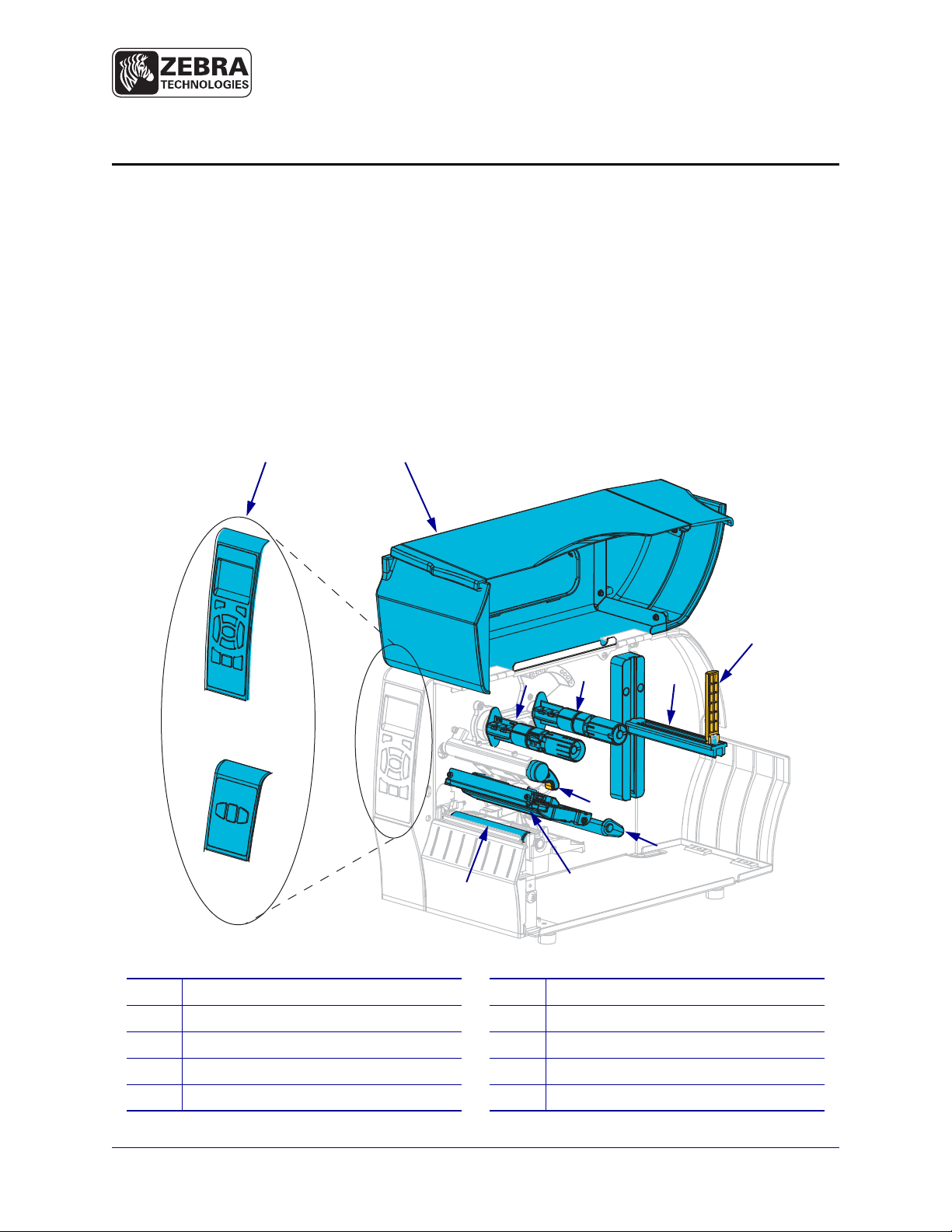
Figure 1 shows the components inside the media compartment of your printer. Depending on
the printer model and the installed options, your printer may look slightly different. The
components that are labeled are mentioned in procedures throughout this manual.
Figure 1 • Printer Components
Control panel
1
Media door
2
Ribbon take-up spindle
3
Ribbon supply spindle
4
Media supply hanger
5
© 2011 ZIH Corp. All product names and numbers are Zebra
trademarks, and Zebra and the Zebra logo are registered
trademarks of ZIH Corp. All rights reserved.
10
Media supply guide
6
Media dancer assembly
7
Printhead-open lever
8
Print mechanism
9
Platen roller
P1041227-003 Rev. A
12/08/2011
Page 2
Control Panel
6
13
12
9
8
11
10
1 2 3 4 5
14 15 16
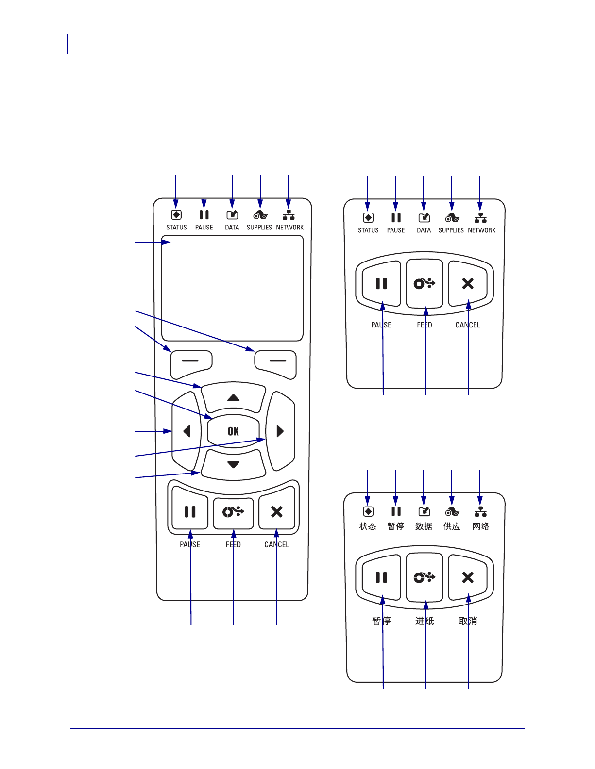
Figure 2 • ZT230 Control Panel
7
14 15 16
1 2 3 4 5
Figure 3 • ZT220 Control Panel
14 15 16
1 2 3 4 5
Figure 4 • ZT210 Control Panel
2
Control Panel
The control panel indicates the printer’s operating status and allows the user to control basic
printer operation.
P1041227-003 ZT210/ZT220/ZT230 Quick Reference Guide 12/08/2011
Page 3
Control Panel
3
1
2
3
4
5
6
7
8
9
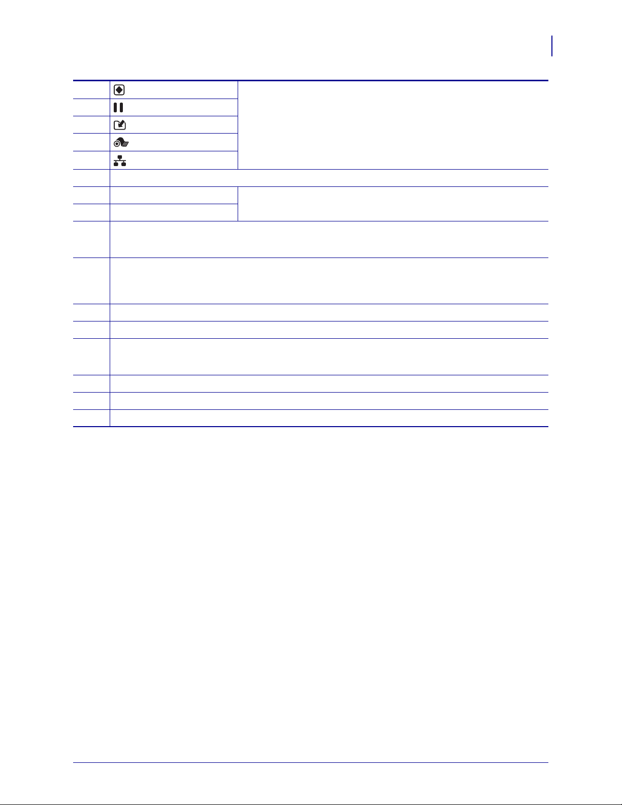
STATUS light These indicator lights show the current status of the printer. For more
PAUSE light
information, see Table 1 on page 7.
DATA light
SUPPLIES light
NETWORK light
The display shows the printer’s operating status and allows the user to navigate the menu system.
RIGHT SELECT button These buttons execute the commands shown directly above them in the
LEFT SELECT button
display.
The UP ARROW button changes the parameter values. Common uses are to increase a value or to
scroll through choices.
The OK button operates as follows:
10
• When on the Home screen, pressing OK enters the menu system.
• When in the menu system, pressing OK accepts the values shown.
The LEFT ARROW button, which is active only in the menu system, navigates to the left.
11
The RIGHT ARROW button, which is active only in the menu system, navigates to the right.
12
The DOWN ARROW button changes the parameter valu es. Common uses are to decrease a value
13
or to scroll through choices.
The PAUSE button starts or stops printer operation when pressed.
14
The FEED button forces the printer to feed one blank label each time the button is pressed.
15
The CANCEL button cancels print jobs when the printer is paused.
16
12/08/2011 ZT210/ZT220/ZT230 Quick Reference Guide P1041227-003
Page 4
Preparing the Printer for Use
4
Preparing the Printer for Use
After you have familiarized yourself with the printer components, prepare the printer for use.
Caution • When you are loading media or ribbon, remove all jewelry that could come into
contact with the printhead or other
Caution • Before touching the printhead assembly, discharge any built-up static electricity
by touching the metal
To set up the printer, complete these steps:
1. Select a location for the printer that meets these conditions:
• The surface must be solid and level of sufficient size and strength to hold the printer.
• The area must include enough space for ventilation and for accessing the printer
components and connectors
• The printer should be within a short distance of an appropriate power outlet that is
easily accessible
printer frame or by using an anti-static wriststrap and mat.
printer parts.
• The printer must be within range of your WLAN radio (if applicable) or within an
acceptable range for other connectors to reach your data source (usually a computer).
For more information on maximum cable len gths and configuration, refer to the User
Guide.
2. Unpack and inspect the printer. If necessary, report any shipping damage. For more
information, refer to the User Guide.
3. Place the printer in the preselected location.
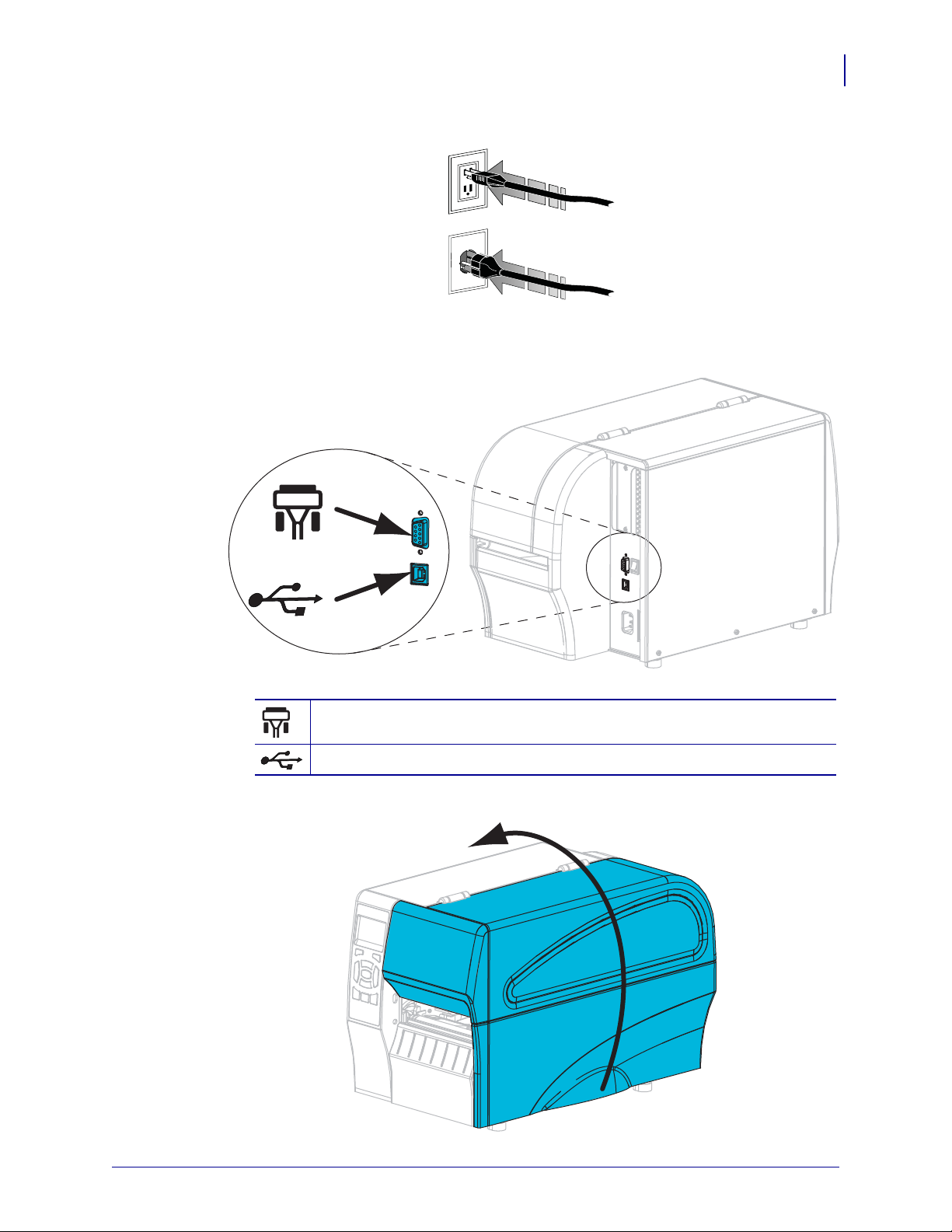
4. Plug the female end of the A/C power cord into the A/C power connector on the back of
the printer.
P1041227-003 ZT210/ZT220/ZT230 Quick Reference Guide 12/08/2011
Page 5
Preparing the Printer for Use
115 V AC
230 V AC
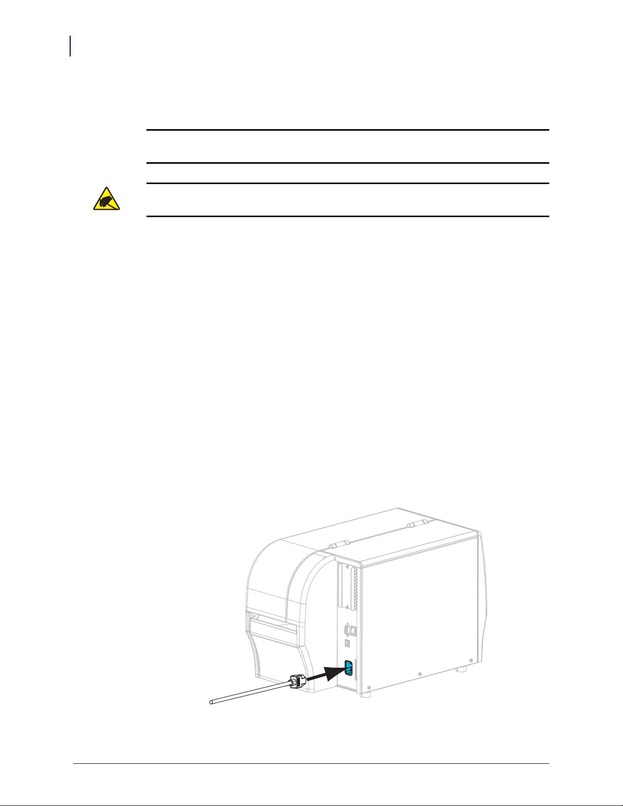
5. Plug the male end of the A/C power cord into an appropriate power outlet.
5
6. Connect the printer to a computer using one or more of the available connections. The
standard connections are shown here. A ZebraNet
®
wired or wireless print server option
or a parallel port may also be present on your printer.
Serial port
USB 2.0 port
7. Raise the media door.
12/08/2011 ZT210/ZT220/ZT230 Quick Reference Guide P1041227-003
Page 6
Preparing the Printer for Use
6
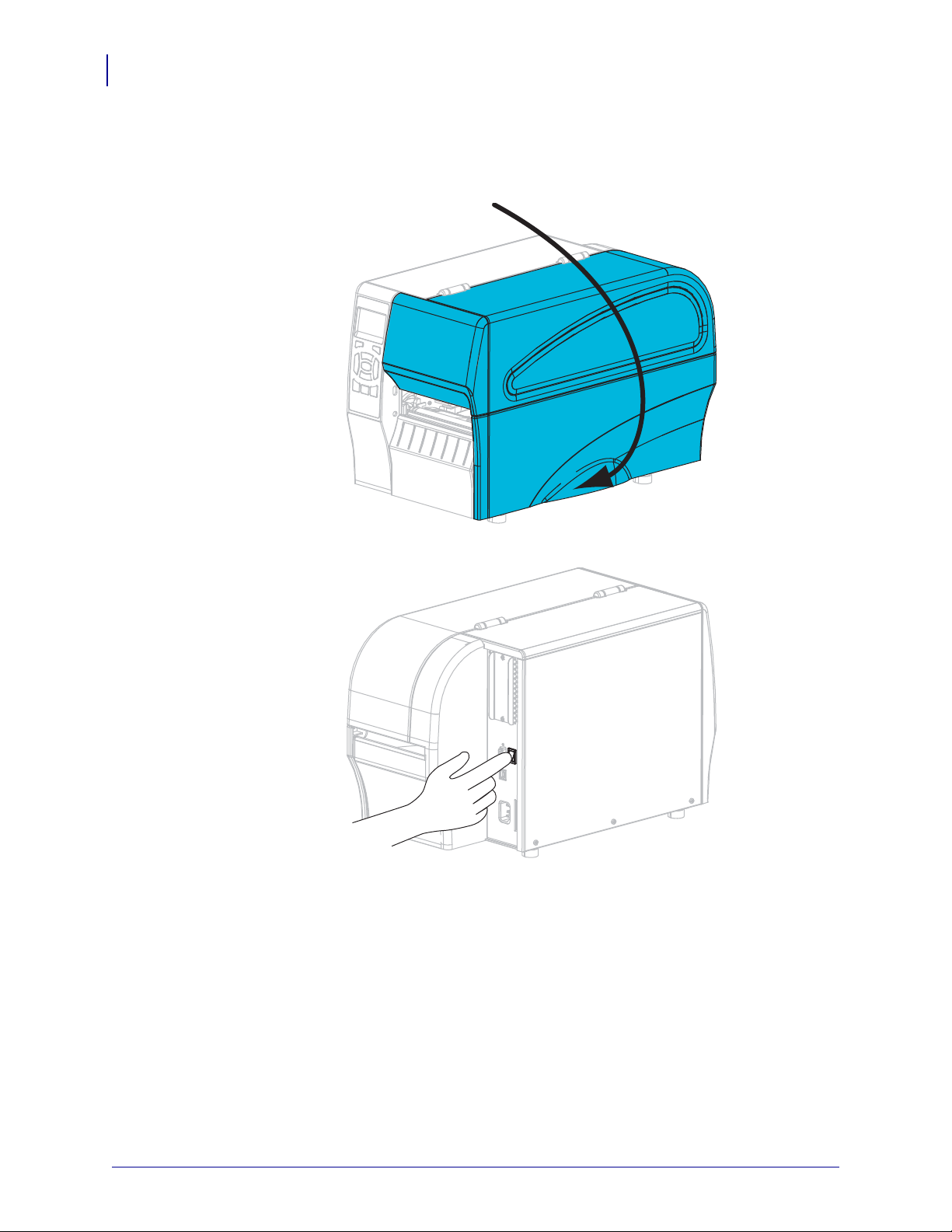
8. Load ribbon (if using Thermal Transfer mode) and media into the printer (see Load
9. Close the media door.
Ribbon and Media on page 9).
10. Turn o n (I) the printer.
The printer boots up and performs a self-test. The results of the self-test are shown in
Table 1.
P1041227-003 ZT210/ZT220/ZT230 Quick Reference Guide 12/08/2011
Page 7

Preparing the Printer for Use
Table 1 • Status of Printer As Shown by Indicator Lights
STATUS light steady green (other lights steady yellow for
2 seconds during printer power-up)
The printer is ready.
STATUS light steady red
SUPPLIES light steady red
The media supply is out. The printer needs attention and
cannot continue without user intervention.
STATUS light steady red
SUPPLIES light flashing red
The ribbon supply is out. The printer needs attention and
cannot continue without user intervention.
STATUS light steady yellow
SUPPLIES light flashing yellow
The printer is in Direct Thermal mode, which does not
require ribbon; however, ribbon is installed in the printer.
7
STATUS light steady red
PAUSE light steady yellow
The printhead is open. The printer needs attention and
cannot continue without user intervention.
STATUS light steady yellow
The printhead is over temperature.
Caution • The printhead may be hot and could
cause severe burns. Allow the printhead to cool.
STATUS light flashing yellow
This indicator light flashing indicates one of the following:
• The printhead is under temperature.
• The media or ribbon supply is over temperature.
• The main logic board (MLB) is over temperature.
STATUS light steady red
PAUSE light steady red
DATA light steady red
The printhead was replaced with one that is not a genuine
Zebra™ printhead. Install a genuine Zebra™ printhead to
continue.
STATUS light flashing red
The printer is unable to read the dpi setting of the
printhead.
12/08/2011 ZT210/ZT220/ZT230 Quick Reference Guide P1041227-003
Page 8

Preparing the Printer for Use
8
Table 1 • Status of Printer As Shown by Indicator Lights (Continued)
Printers with a ZebraNet wired Ethernet option
Printers with a ZebraNet wireless option
NETWORK light off
No Ethernet link is available.
NETWORK light steady green
A 100 Base link was found.
NETWORK light steady yellow
wired Ethernet—A 10 Base link was found.
NETWORK light steady red
An Ethernet error condition exists. The printer is not
connected to your network.
NETWORK light off
A radio was found during power-up. The printer is
attempting to associate with the network. The light flashes
red while the printer associates with the network. The l ight
then flashes yellow while the printer is authenticating with
the network.
NETWORK light steady green
The radio is associated with your network and
authenticated, and the WLAN signal is strong.
NETWORK light flashing green
WLAN—The radio is associated with your network and
authenticated, but the WLAN signal is weak.
NETWORK light steady red
A WLAN error condition exists. The printer is not
connected to your network.
P1041227-003 ZT210/ZT220/ZT230 Quick Reference Guide 12/08/2011
Page 9

Load Ribbon and Media
Use the instructions in this section to load ribbon and to load roll media in Tear-Off mode.
Note • The components inside your printer are color-coded.
• The touch points that you will need to handle are colored gold inside the printers and are
highlighted in gold in the illustrations in this manual.
• The components associated with the ribbon system are made of black plastic, while the
components associated with media are made of gray plastic. Those components and
others are highlighted in light blue in the illustrations in this manual as needed.
Loading Ribbon Ribbon is used only with thermal transfer labe ls. For direct thermal labels,
do not load ribbon in the printer (omit steps 2 through 6 in the following procedure).
Important • Use ribbon that is wider than the media to protect the printhead from wear.
Ribbon must be coated on the outside (refer to the User Guide for more information).
Note • The maximum ribbon length for the ZT210 and ZT220 is 984 ft (300 m). The
maximum ribbon length for the ZT230 is 1476 ft (450 m).
Load Ribbon and Media
9
Loading Media For instructions for loading fanfold media or for loading in different print
modes, refer to the User Guide.
12/08/2011 ZT210/ZT220/ZT230 Quick Reference Guide P1041227-003
Page 10

Load Ribbon and Media
1
2
10
Caution • When you are loading media or ribbon, remove all jewelry that could come into
contact with the printhead or other
printer parts.
To load ribbon and roll media in Tear-Off mode, complete these steps:
1.
Caution • The printhead may be hot and could cause severe burns. Allow the
printhead to cool.
Rotate the printhead-open lever (1) counterclockwise to release the prin t mechanism (2).
Loading Ribbon
2. Position the ribbon with the loose end unrolling clockwise.
P1041227-003 ZT210/ZT220/ZT230 Quick Reference Guide 12/08/2011
Page 11

Load Ribbon and Media
3. Place the roll of ribbon on the ribbon supply spindle. Push the roll back as far as it will go.
4. Your printer shipped with an empty ribbon core on the ribbon take-up spindle. If this core
is no longer there, place an empty ribbon core on the ribbon take-up spindle. Push the core
back as far as it will go.
11
12/08/2011 ZT210/ZT220/ZT230 Quick Reference Guide P1041227-003
Page 12

Load Ribbon and Media
12
5. Slide the ribbon under the print mechanism.
6. Wind the ribbon clockwise around the core on the ribbon tak e-up spindle. T urn the spind le
enough to wind the ribbon around it several times.
P1041227-003 ZT210/ZT220/ZT230 Quick Reference Guide 12/08/2011
Page 13

Load Ribbon and Media
Loading Media
7. Remove and discard any tags or labels that are dirty or that are held by adhesives or tape.
13
8. Slide out and flip down the media supply guide.
12/08/2011 ZT210/ZT220/ZT230 Quick Reference Guide P1041227-003
Page 14

Load Ribbon and Media
14
9. Place the roll of media on the media supply hanger. Push the roll back as far as it will go.
10. Flip up the media supply guide.
P1041227-003 ZT210/ZT220/ZT230 Quick Reference Guide 12/08/2011
Page 15

11. Slide in the media supply guide until it touches the edge of the roll.
12. Slide the outer media guide all the way out.
Load Ribbon and Media
15
12/08/2011 ZT210/ZT220/ZT230 Quick Reference Guide P1041227-003
Page 16

Load Ribbon and Media
1
2
16
13. Slide the media under the media dancer assemb ly and the print mechanism. Al low the end
of the media to extend out of the front of the printer.
14. Make sure that the media passes through the slot in the transmissive media sensor (1) and
under the inner media guide (
2). The media should just touch the back of the transmissive
media sensor slot.
P1041227-003 ZT210/ZT220/ZT230 Quick Reference Guide 12/08/2011
Page 17

Load Ribbon and Media
15. Slide in the outer media guide until it just touches the edge of the media.
17
16. Rotate the printhead-open lever clockwise until it locks the printhead in place.
17. If necessary, press PAUSE to enable printing.
12/08/2011 ZT210/ZT220/ZT230 Quick Reference Guide P1041227-003
Page 18

Load Ribbon and Media
18
Remove Used Ribbon
Remove used ribbon from the ribbon take-up spindle each time you change the roll of ribbon.
To remove used ribbon, complete these steps:
1. Has the ribbon run out?
If the ribbon... Then
Ran out Continue with the next step.
Did not run out Cut or break the ribbon before the ribbon take-up spindle.
2. Slide the core with the used ribbon off of the ribbon take-up spindle.
3. Discard the used ribbon. Y ou may reuse the empty core from the ribbon supply spindle by
moving it to the ribbon take-up spindle.
P1041227-003 ZT210/ZT220/ZT230 Quick Reference Guide 12/08/2011
 Loading...