

Page 1

WiNG Express 5.8.2
MN-002676-01
Access Point
User Guide
Page 2

Zebra and the Zebra head graphic are registered trademarks of ZIH Corp. The Symbol logo is a
registered trademark of Symbol Technologies, Inc., a Zebra Technologies company.
© 2015 Symbol Technologies, Inc.
Page 3

Contents
Introduction to WiNG Express ..................................................................................5
Basic WiNG Express Access Point Configuration ...................................................9
Dashboard ...............................................................................................................17
Dashboard ..................................................................................................................................... 17
Monitor......................................................................................................................19
Radios ............................................................................................................................................. 19
Details................................................................................................................................... 22
WLANs ............................................................................................................................................. 23
Details................................................................................................................................... 25
Clients ............................................................................................................................................. 26
Details................................................................................................................................... 27
Application Visibilty ...................................................................................................................... 29
Application ......................................................................................................................... 29
Category ............................................................................................................................. 31
Configuration ...........................................................................................................33
Basic ................................................................................................................................................ 33
LAN .................................................................................................................................................. 36
WAN ................................................................................................................................................ 38
Wireless ........................................................................................................................................... 41
Security ........................................................................................................................................... 51
Firewall ................................................................................................................................. 52
WIPS ...................................................................................................................................... 55
Application Visibil ity ........................................................................................................... 57
Schedule Policy .................................................................................................................. 59
Services .......................................................................................................................................... 60
DHCP .................................................................................................................................... 60
RADIUS .................................................................................................................................. 62
Management ................................................................................................................................ 65
Access Points ................................................................................................................................. 68
Event History .............................................................................................................73
Event History .................................................................................................................................. 73
Customer-Support ...................................................................................................75
Page 4

Page 5

INTRODUCTION TO
Chapter 1
WING EXPRESS
Zebra’s WiNG Express Access Points are specifically designed to meet the wireless deployment
and radio coverage needs of small and mid-size businesses without compromising on Zebra’s
WLAN enterprise-class feature set and functionality.
WiNG Express is a simplified version of the existing operating system currently shipping with the
WiNG family of controllers, service platforms and Access Points. WiNG Express Access Points
utilize an easy-to-use, easy-to-understand graphic user interface that simplifies end-to-end
WLAN management. WiNG Express enables the creation of a fully network-aware WLAN with
the intelligence required to route wireless transmissions as efficiently and securely as possible.
Within a WiNG Express managed network, a single Access Point can manage a network of up to
24 peer model Access Points, eliminating the need for a managing controller resource, thus
simplifying initial deployments and their costs. Express Access Points can automatically
discover, connect and provision peer model Access Points with a pre-defined network profile in
just minutes.
Zebra’s WiNG Express Access Point portfolio consists of two dual radio 802.11ac Access Points
(AP 7502E and AP 7522E) and four 802.11n Access Points (AP 6511E, AP 6521E, AP 6522E
and AP 6562E).
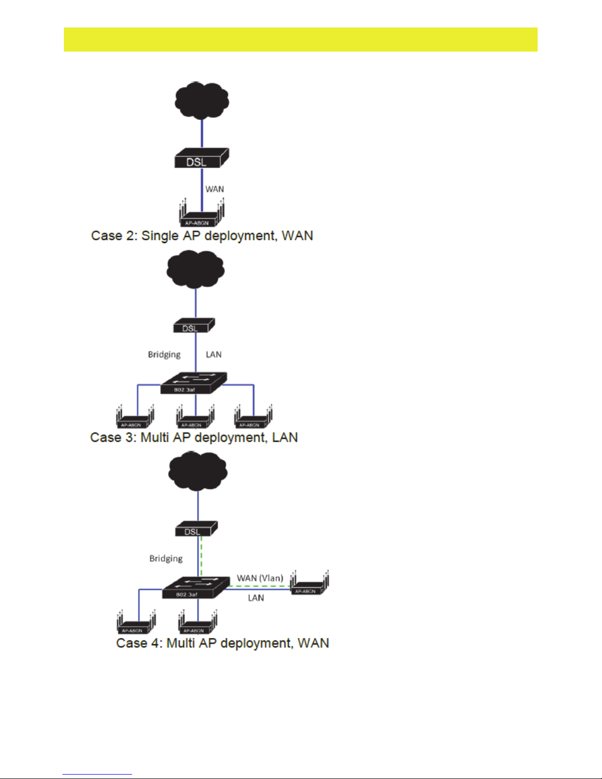
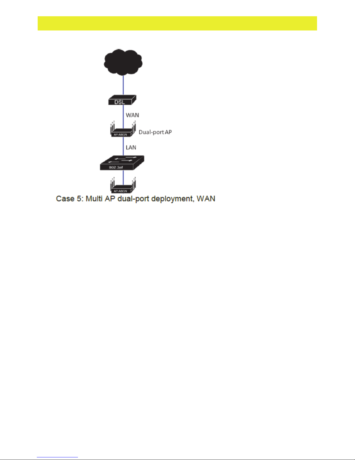
WiNG Express is designed for single-site Access Point deployments not exceeding more than 24
Access Points of the same model. The following network deployment cases are specifically
targeted:
Page 6
WiNG Express Version 5.8.2 Users Guide 6
Page 7
WiNG Express Version 5.8.2 Users Guide 7
Page 8

Page 9

BASIC WING EXPRESS ACCESS
Chapter 2
POINT CONFIGURATION
For a WiNG Express SKU Access Point, both the WiNG Express UI and an Over The Air (OTA)
provisioning configuration are required for a basic setup and network connection.
To provide the Access Point a basic configuration and access WiNG Express management
functions:
1 Power up the Access Point.
The Access Point can be powered using an appropriately rated power adapter, POE injector
or POE switch resource.
2 Connect to the Access Point.
Connect to the WiNG Express SSID. For Windows systems, locate the SSID by selecting
the network icon on the bottom right corner of the screen. For MAC systems, locate the
SSID by selecting the network icon on the top right corner of the screen.
Open a browser (Chrome, Firefox or Internet Explorer) and enter
https://express.zebra.com (https://express.zebra.com).
The login screen displays.
3 Enter the default username admin in the Username field.
4 Enter the default password admin123 in the Password field.
5 Select the Login button to load the management interface.
If this is the first time the WiNG Express interface has been accessed, a screen displays
prompting for the Access Point’s country code.
6 Select the Country Code specific to this Access Point’s deployment location.
Page 10
WiNG Express Version 5.8.2 Users Guide 10
Selecting the correct country is central to legal operation. Each country has its own
regulatory restrictions concerning electromagnetic emissions and the maximum RF signal
strength that can be transmitted. Select Apply to implement the selected Country Code.
SKU's only support certain countries (for example: a US SKU only includes US, Guam,
Puerto Rico, American Samoa, US Virgin Islands and Mariana Island).
The Access Point automatically displays a Dashboard where users can assess network
health and conduct a diagnostic review of Access Point performance.
Note: At some point in the Access Point’s initial setup, the default password should be changed
to enhance the security of the network. Refer to the Configuration > Management screen to
change the default password to a more secure password.
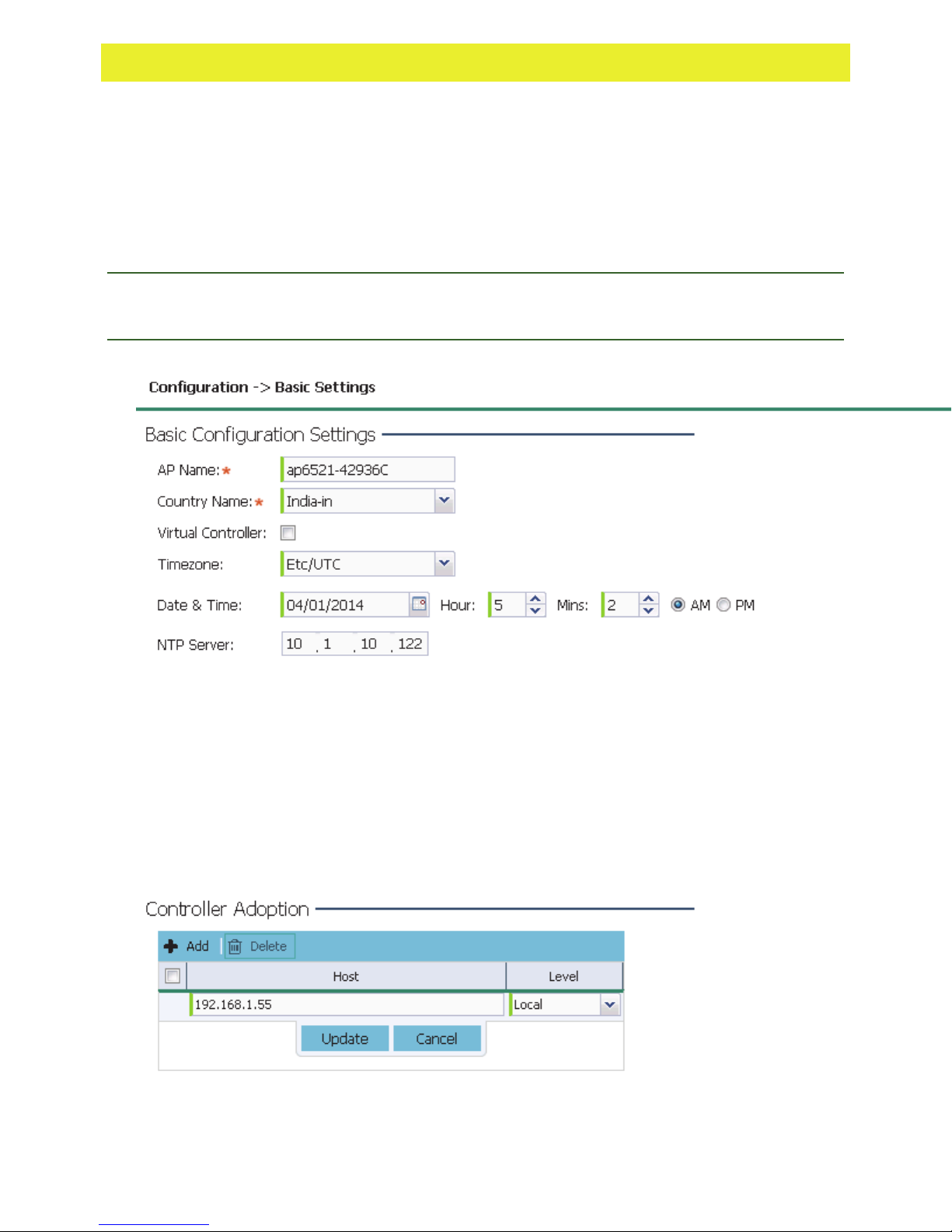
7 Expand the Configuration menu item and select Basic.
8 Set the following Basic Configuration Settings for this Access Point:
Page 11
WiNG Express Version 5.8.2 Users Guide 11
AP Name - Provide an AP Name used as this Access Point’s WiNG Express network
identifier. If setting this Access Point as a Virtual Controller, each Access Point managed
by this Virtual Controller lists this Access Point’s AP Name as its own. The AP Name is a
required parameter.
Country Code - If the Country Code was not set when the Access Point was initially
powered on, set the country now to ensure the Access Point’s legal operation. The
Access Point’s wireless capabilities are disabled until the required country code is set.
Virtual Controller - Select this option to define this Access Point as a Virtual Controller
capable of managing and provisioning up to 24 Access Points of the same model. If
selecting this Access Point as a Virtual Controller, those Access Points managed by this
Virtual Controller will list this Access Point’s AP Name as its own. Only one Virtual
Controller can be designated.
Timezone - Use the drop-down menu to specify the geographic timezone where the
Access Point is deployed. Different geographic time zones have daylight savings clock
adjustments, so specifying the timezone correctly is important to account for geographic
time changes.
Date & Time - Set the date, hour and minute for the Access Point’s current system time.
Specify whether the current time is in the AM or PM.
NTP Server - Optionally provide the IP address of a NTP server resource. Network Time
Protocol (NTP) manages time and/or network clock synchronization within the WiNG
Express network. NTP is a client/server implementation. Access Points (NTP clients)
periodically synchronize their clock with a master clock (an NTP server). For example, an
Access Point resets its clock to 07:04:59 upon reading a time of 07:04:59 from its
designated NTP server.
Controller Adoption - To adopt a controller enter the IP address in the Host filed and
select a Level from the drop-down menu.
9 Select Apply to implement the updates. Select Apply to implement the updates.
10 Expand the Configuration menu item and select WAN.
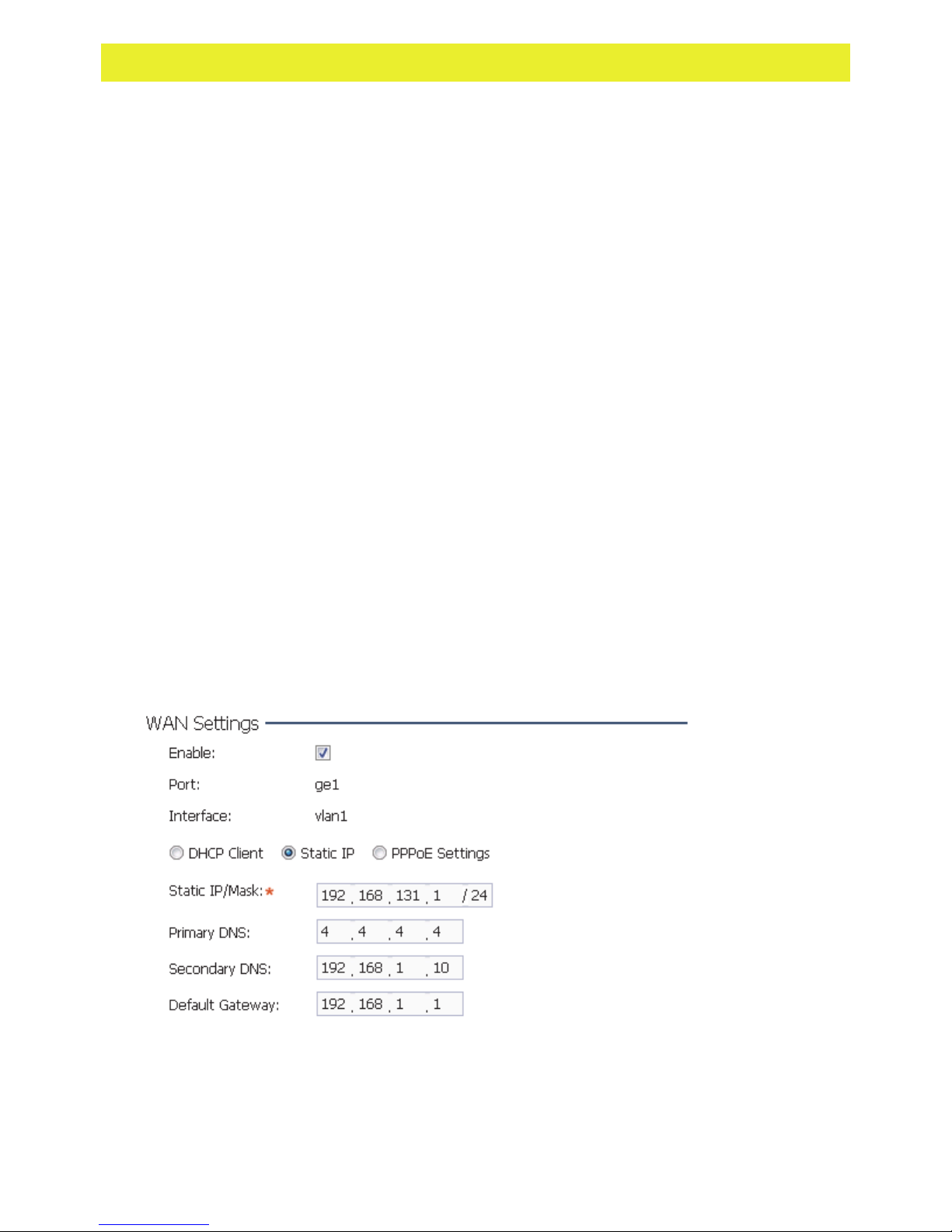
11 Refer to the WAN Settings field and set the following:
Enable - Select this option to allow a connection between the Access Point and a larger
network or outside world through the WAN port. Disable this option to isolate the WAN
connection. No connections to a larger network or Internet are possible. Clients cannot
communicate beyond configured subnets. Both the physical Port used to connect to the
WAN and the virtual Interface (VLAN) are also listed and fixed.
Page 12
WiNG Express Version 5.8.2 Users Guide 12
DHCP Client - Select this option to enable DHCP for the Access Point WAN connection.
This is useful, if the target network or Internet Service Provider (ISP) uses DHCP. DHCP
is a protocol that includes mechanisms for IP address allocation and delivery of host-
specific configuration parameters from a DHCP server to a host. Some of these
parameters are IP address, network mask, and gateway. The WAN and LAN ports should
not both be configured as DHCP clients.
Static IP - Select this option to bypass DHCP address allocation resources and manually
set the IP address for the Access Point’s WAN connection. Manually provide the Access
Point’s Static IP/Mask and Default Gateway.
PPPoE Settings - Optionally enable Point-to-Point Protocol over Ethernet (PPPoE) on the
WAN network. If PPPoE is enabled, provide the required Auth Type, Login Name and
Login Password. Server Name and Default Gateway are optional settings. PPP is a data-
link protocol for dialup connections allowing an Access Point to use a broadband modem
(DSL, cable modem, etc.) for access to high-speed data and broadband networks. Most
DSL providers support (or deploy) the PPPoE protocol. PPPoE uses standard encryption,
authentication, and compression as specified by the PPPoE protocol. PPPoE enables the
Access Point to establish a point-to-point connection to an ISP over an existing Ethernet
interface.
Static IP / Mask - Specify an IP address for the WAN connection if using static address
assignment for the WAN port. An IP address uses a series of four numbers expressed in
dot notation, for example, 190.188.12.1. Additionally, specify a Mask for the Access
Point’s WAN connection. This number is available from the ISP for a DSL or cable-
modem connection, or from an administrator if the Access Point connects to a larger
network.
Primary/Secondary DNS/Default Gateway - If using a static IP or DHCP, enter the
Primary and Secondary DNS server resource’s numerical IP address and Default
Gateway.
Note: If segmenting traffic between the Access Point’s WAN and LAN, you’ll need to create a
VLAN. Complete steps 13 and 14 to define the required VLAN. Otherwise, proceed to step 15.
12 Select Apply to implement the updates.
13 Expand the Configuration menu item and select Access Points. Each AP Name displays
as a link that can be selected to update the configuration of that specific Access Point. Select
a target AP Name link from amongst those displayed in the Access Points screen.
Page 13
WiNG Express Version 5.8.2 Users Guide 13
Refer to the LAN IP Interface Settings field, and add a VLAN and Static IP as required for
enabling DHCP (within the Configuration > Services screen) for client IP address requests
and ensuring routable traffic.
14 Select Apply to commit the updates to the selected Access Point’s configuration.
15 Expand the Configuration menu item and select Wireless.
The Wireless screen displays fields where Radio Settings and Wireless LAN settings can be
defined. Default radio settings remain as is for the Access Point’s basic setup.
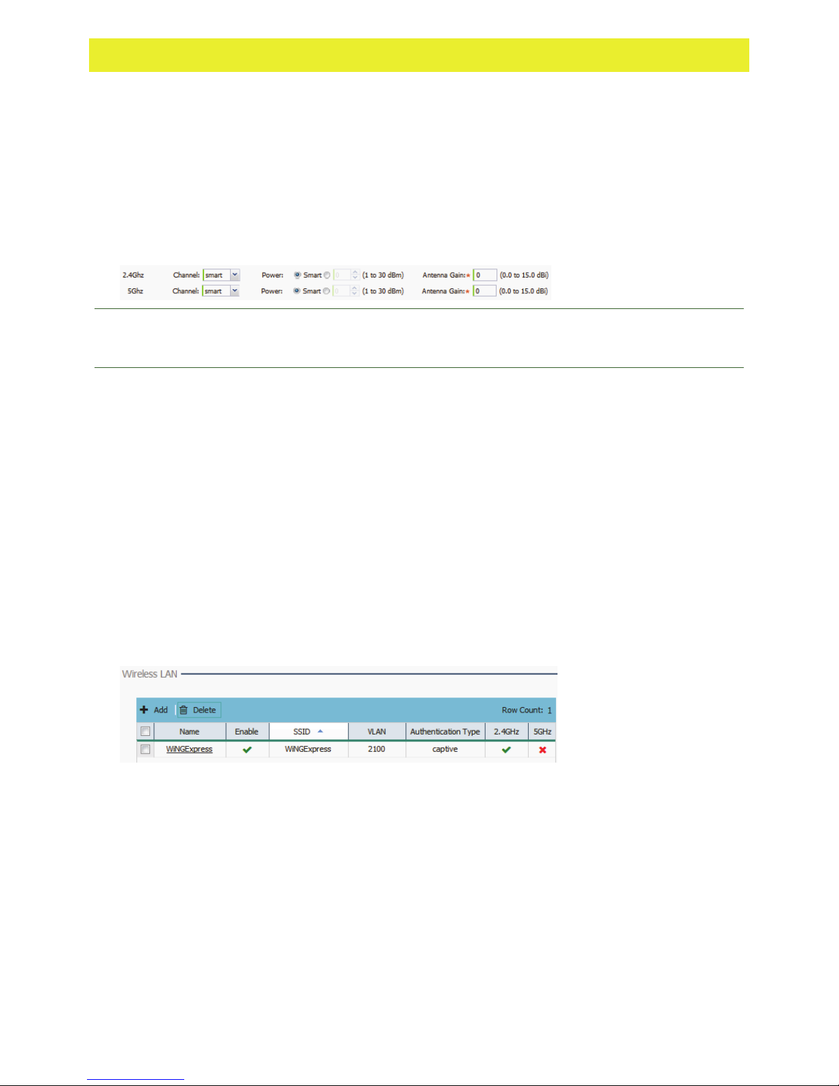
In respect to the Radio Settings, the professional installer should be aware of the following:
Note: The above example includes a field for setting the antenna gain. This setting is only
available for external antenna model Access Points and does not display for internal antenna
model Access Points.
The Channels available for configuration are channels for which the product is approved
in its selected country. The professional installer must ensure the product is set to
operate under conditions, and on channels, approved by country regulations.
Selecting Smart as the Power setting automatically configures radio power to not exceed
the maximum power allowed by the defined country. For static power settings, the
professional installer must ensure the configured power levels are compliant with local
and regional regulations. The county selected automatically limits the maximum output
power that can be set.
For external antenna model Access Points, configure the Antenna Gain based on the
antenna used in the deployment. The set gain value should include the antenna gain,
along with any additional components, such as extension cables used between the
Access Point and the antenna.
In respect to the Wireless LAN settings, the professional installer should be aware WiNG
Express Access Points ship with a default WLAN (WINGExpress). However, this WLAN does
not provide adequate authentication to protect from unauthorized user access. An additional
WLAN configuration can be created and validated before deleting default WLAN.
Page 14
WiNG Express Version 5.8.2 Users Guide 14
16 To create a new WLAN, select + Add from the upper, left-hand side of the Wireless LAN
field.
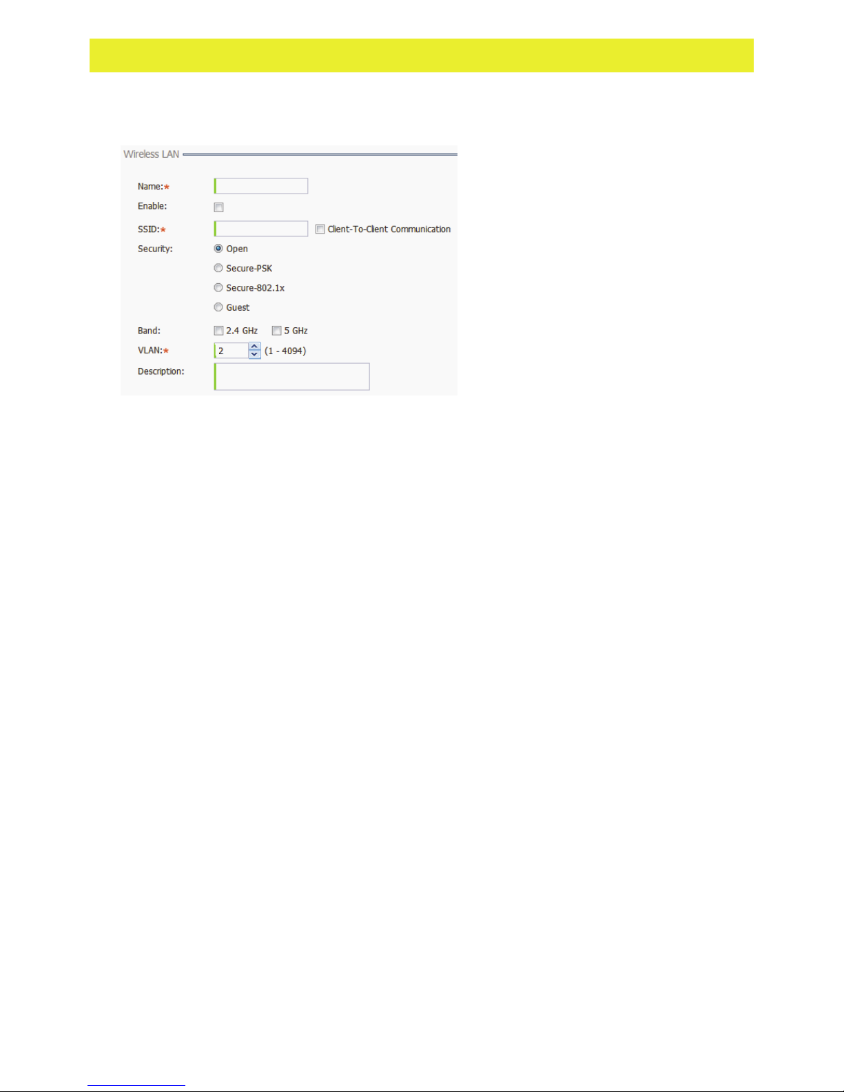
17 Set the following configuration attributes for the new WLAN:
Name - Provide a unique name for the WLAN as its network identifier. This is a required
setting.
Enable - Select this setting to enable this WLAN within the Access Point managed
network and to provide some measure of data protection not available in the default
WLAN.
SSID - Specify the WLAN's SSID. The WLAN SSID is case sensitive and alphanumeric.
SSID length should not exceed 32 characters. This is a required setting. Select Client-
To-Client Communication to enable client interoperability within this WLAN. The default
is disabled, meaning clients are not allowed to exchange packets with other clients. It
does not necessarily prevent clients on other WLANs from sending packets to this WLAN,
but if this setting is disabled on the other WLAN, clients are not permitted to interoperate
at all.
Security - The screen displays with the Open option selected. Naming and saving such a
policy (as is) would provide no security and might only make sense in a network wherein
no sensitive data is either transmitted or received. This default setting is not
recommended.
If selecting Secure-PSK, select an encryption type of WEP-64, WEP-128, TKIP-CCMP or
WPA2-CCMP. When the encryption type is selected, enter an encryption key. Define
whether the key is entered in ASCII or HEX characters. Detailed security and encryption
information is available in the Configuration > Wireless section of the documentation.
If selecting Secure-802.1x, provide an IP address (or hostname) and a shared secret
(password) used to access an external RADIUS server resource designated to validate
user requests to the Access Point’s WLAN resources.
Selecting Guest displays fields for captive portal Web page creation, and is beyond the
scope of this basic Access Point configuration.
Band - Select the 2.4 GHz and/or 5 GHz (if supported) radio bands supports by the
Access Point and its connected client traffic. If this Access Point is designated as a Virtual
Controller AP, both radio bands should be enabled.
VLAN - Use the spinner control to specify a VLAN from 1 - 4,094 for this WLAN. When a
client associates with a WLAN, the client is assigned a VLAN by load balance distribution.
Do not use VLAN 1 with the WLAN if the WAN port has been enabled.
Description - Optionally enter a WLAN description to further describe the WLAN’s
deployment objective within the WiNG Express managed network.
Page 15
WiNG Express Version 5.8.2 Users Guide 15
18 Select Apply to commit the updates to the Access Point’s WLAN configuration.
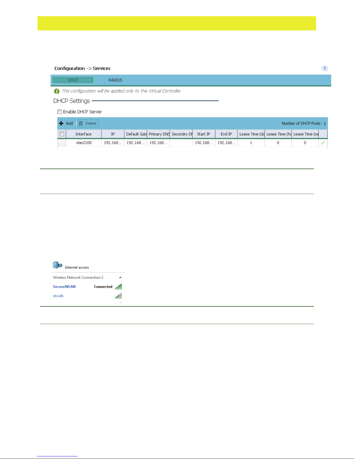
19 Expand the Configuration menu item and select Services.
20 Select Enable DHCP Server to ensure the Access Point can provision IP addresses to
requesting clients over the specified interface.
Note: A VLAN must be already configured and available to the DHCP server as a viable
interface between the Access Point and requesting client. Refer to the LAN IP Interface
Settings field (within the Edit Access Point screen), and add a VLAN.
Select + Add and provide a default gateway, primary dns server, and a starting and ending
IP range of addresses that constitute a pool of addresses available to requesting clients.
Additional DHCP options are available and are documented in the Configuration > Services
> DHCP section.
21 Select Apply to commit the updates to the Access Point’s DHCP configuration.
22 At this point, you’re ready to connect to the network using the security restrictions applied to
the newly created WLAN. Ensure the new secure WLAN has been enabled, and check
whether a client is able to access the network.
Note: Only when the new WLAN configuration is validated as accessible should the existing
WiNG Express default WLAN be deleted.
Page 16

Page 17

DASHBOARD
Chapter 3
In This Chapter
Dashboard ................................................................. 17
Dashboard
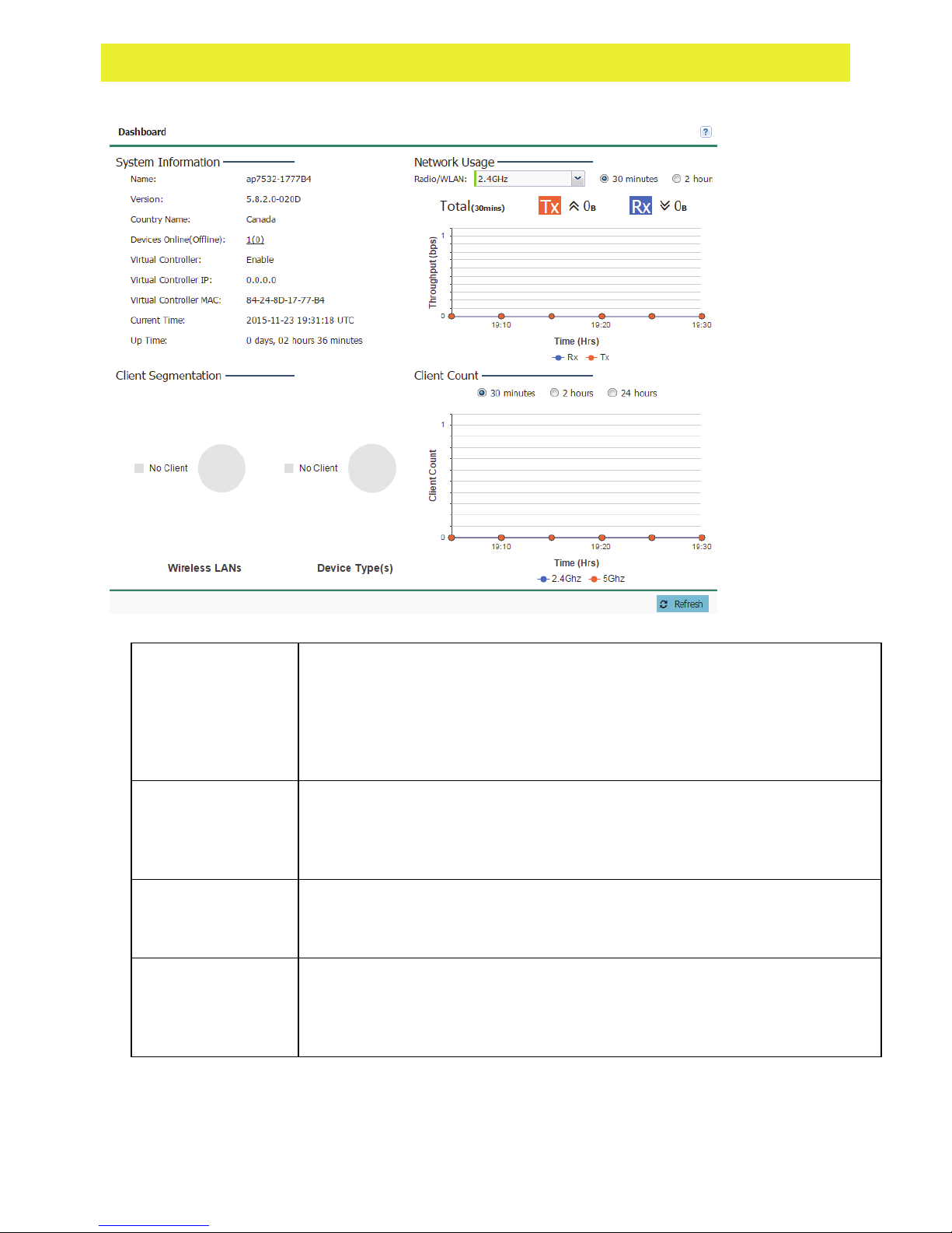
The dashboard enables administrators to review and troubleshoot Access Point managed
network operation. Additionally, the dashboard allows an administrator to assess network
component health and conduct a diagnostic review of device performance.
To review high-level Access Point dashboard information:
1 Select Dashboard in the main menu.
Page 18
WiNG Express Version 5.8.2 Users Guide 18
2 Review the following to assess the health of the network:
System
Information
Displays the administrator assigned Name, software Version, required
Country Name for legal geographic deployment in specific regions, number
of detected Online and Offlline Devices, whether the Access Point has been
enabled as a Virtual Controller to manage peer Access Points, the
designated Virtual Controller IP and MAC addresses, Current Time and Up
Time listing when the Access Point was last offline.
Client
Segmentation
Displays a set of pie charts segregating WLAN utilization amongst peer
Access Points and client types. Use this information to help assess whether
client loads exceed the number and type of WLANs currently deployed with
managed Access Points.
Network Usage
Displays the network throughput (both in the transmit and receive
directions) for the selected Radio or WLAN over the defined trending period
of 30 minutes, 2 hours or 24 hours.
Client Count
Displays total network client count for the selected trending period of 30
minutes, 2 hours or 24 hours. Clients are partitioned into their current
2.4Ghz and 5Ghz radio bands to help assess whether the client load is
adequately supported in each band.
Page 19

MONITOR
Chapter 4
The Monitor screens provide detailed, real-time information about the network and RF health for
Access Point Radios, WLANs and wireless Clients. Use the information on these screens to
track RF traffic, throughput, signal to noise ratio and client health.
In This Chapter
Radios ....................................................................... 19
WLANs ...................................................................... 23
Clients ....................................................................... 26
Application Visibilty .................................................... 29
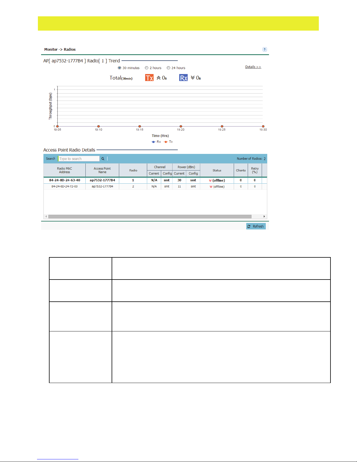
Radios
Use the Radios screen to assess the quality of the Access Point radio's utilization, power
consumption, and client connections.
To monitor managed Access Point radios:
1 Select Monitor from the main menu and click on Radios.
Page 20
WiNG Express Version 5.8.2 Users Guide 20
2 Select a time interval of 30 minutes, 2 hours or 24 hours from the radio buttons at the top
of the page. The graph updates accordingly with the radio's Throughput.
3 Review the following Access Point Radio Details:
Radio MAC
Address
Access Point
Name
Radio
Displays the Media Access Control (MAC) address factory assigned to
each radio as its hardware identifier on the network.
Displays the Access Point's unique administrator assigned name provided
upon initial configuration.
Displays the radio number for each Access Point radio on the network.
AP6511 and AP6521 models are single radio models, other models support
at least two radios.
Channel:
Current / Config
Displays the current channel number each listed Access Point radio is set
to transmit and receive on, as well as its configured channel number. The
Channels available for configuration are channels for which the product is
approved in its selected country. The professional installer must ensure the
product is set to operate under conditions, and on channels, approved by
country regulations.
Page 21

WiNG Express Version 5.8.2 Users Guide 21
Power (dBm):
Current / Config
Displays the current power level in dBm for each Access Point radio as well
as its configured power level. If Smart is the defined power setting, the
radio automatically configures power to not exceed the maximum power
allowed by the defined country. For static power settings, the professional
installer must ensure the configured power levels are compliant with local
and regional regulations. The country selected automatically limits the
maximum output power that can be set.
Status
Displays the current operational status for each Access Point. If an Access
Point is online, two green up arrows display. If an Access Point is offline,
two green down arrows display.
Clients
Displays the number of clients currently associated to each Access Point
radio on the network. AP6511 and AP6521 single radio Access Points
support 128 clients, the other models support up to 256 client connections.
Retry (%)
Displays the retry percentage for packets sent on each Access Point radio.
The retry rate helps assess the overall effectiveness of the RF environment
(as displayed as a percentage) and a function of the connection rate in both
directions.
SNR
Displays the connected client's signal to noise ratio (SNR). SNR is a
measure that compares the level of a desired signal to the level of
background noise. It is defined as the ratio of signal power to the noise
power. A SNR of 45 or higher indicates excellent RF performance. A SNR
of less than 15 indicates poor RF performance. A low SNR could warrant a
different Access Point connection to improve performance.
4 Select Details to assess individual Access point radio utilization data in greater detail.
Page 22
WiNG Express Version 5.8.2 Users Guide 22
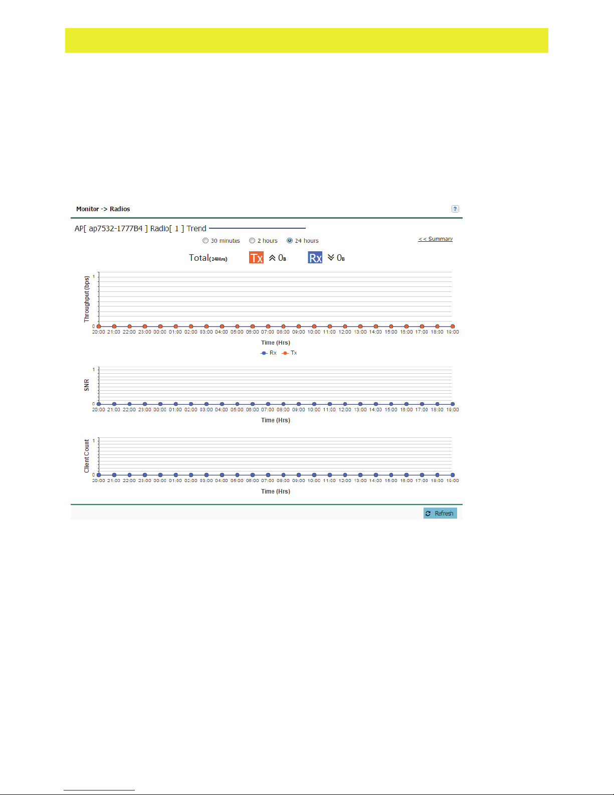
Details
Access Point radio data can be analyzed to define periods where the radio's transmit and
receive capabilities are jeopardized, or whether noise detected on the network is excessive and
warrants administration. Client connections can also be reviewed to determine if the radio has an
optimal number of connected client devices in respect to periods when the radio is over/under
utilized.
To review Access Point radio details:
1 Select Monitor from the main menu and select Radios. Select a radio, then Details.
2 Select a reporting interval of 30 minutes, 2 hours or 24 hours from the radio buttons at the
top of the page. The graph updates accordingly with the radio's Throughput, SNR and
Client Count.
3 Review the Throughput (bps) table to assess periods of heavy or light transmission and
receive utilization over trended periods.
Transmitted packets display in blue, received packets in green.
4 Refer to the SNR field to assess periods where the Access Point's radio quality could be
compromised due to excessive noise on the network.
Signal to noise ratio (SNR) is an interference measurement to help administrators assess
whether an Access Point needs load balancing with the assistance of neighbor radios.
Additionally, a low SNR could warrant power compensation to account for poorly performing
radios. A SNR of 45 or higher indicates excellent RF performance. A SNR of less than 15
indicates poor RF performance.
5 Use the Client Count table to help determine whether the client load should be increased or
decreased based on radio under/over utilization (throughput) and the level of interference
detected on the managed network.
Page 23
WiNG Express Version 5.8.2 Users Guide 23
AP6511 and AP6521 single radio Access Points support 128 clients, other models support
up to 256 client connections.
6 To return to the parent radio screen, select << Summary in the upper, right-hand, side of the
graph.
WLANs
A WLAN can be advertised from a single Access Point radio or can span multiple Access Points
and radios. WLAN configurations can be defined to only support specific areas of a site. For
example, a guest access WLAN may only be mapped to a 2.4GHz radio in a lobby or conference
room providing limited coverage, while a data WLAN is mapped to all 2.4GHz and 5GHz radios
at the branch site providing complete coverage.
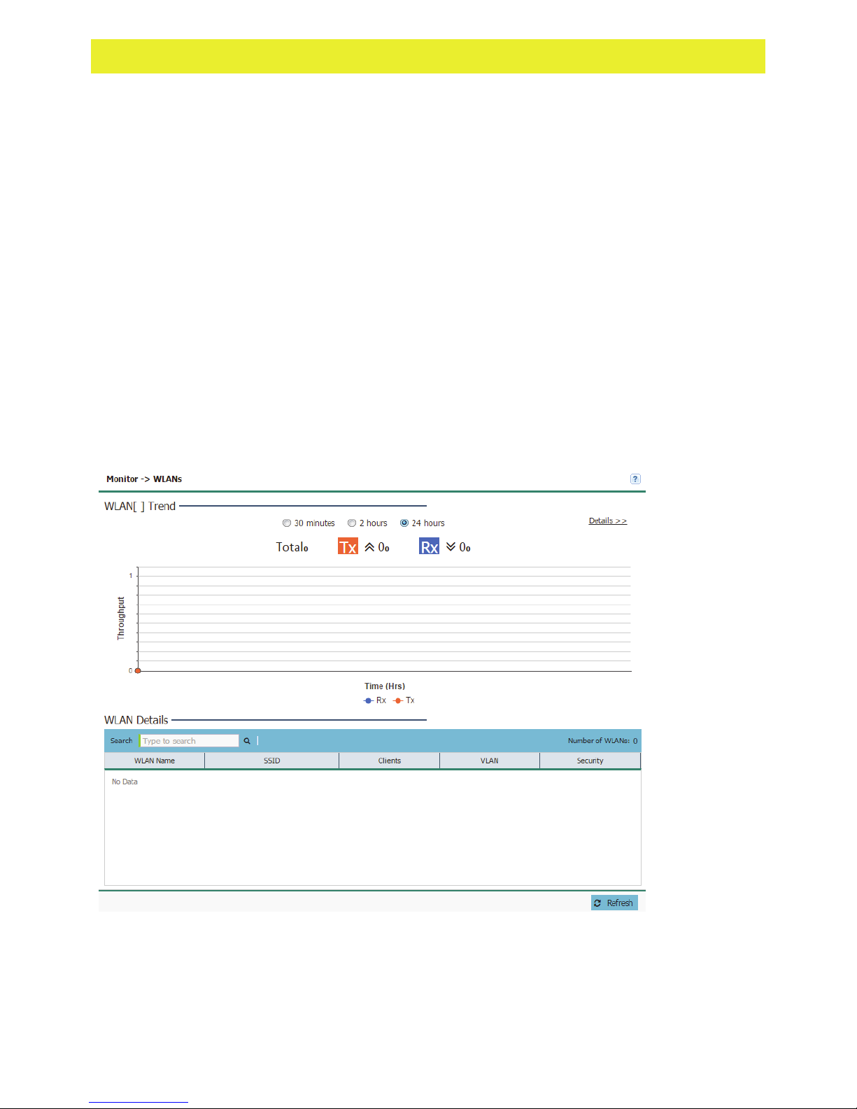
Periodically refer to the WLANs screen to monitor an Access Point's WLAN utilization and
whether WLAN usage is consistent with an Access Point's deployment objective and the security
needs of its connected clients.
To review Access Point's WLAN utilzation:
1 Select Monitor from the main menu and select WLANs.
2 Select a reporting interval of 30 minutes, 2 hours or 24 hours from the radio buttons at the
top of the page. The graph updates accordingly with the radio's Throughput.
3 Review the following WLAN information to help determine whether the Access Point's WLAN
utilization is optimally set for its deployment objective:
Page 24

WiNG Express Version 5.8.2 Users Guide 24
WLAN Name
SSID
Clients
VLAN
Security
Displays the administrator defined WLAN name for each of the WLANs.
Spaces between words are not permitted in the name. The name could be
a logical representation of the WLAN's coverage area (engineering,
marketing etc.). The name cannot exceed 32 characters.
Displays the Services Set Identification (SSID) associated with the WLAN.
The maximum number of characters for the SSID is 32.
Displays the collective number of clients comprising the WLAN's
membership, as pooled from each of the Access Points in this listed WLAN.
Displays the VLAN ID to which the WLAN is mapped.
Displays the encryption and/or authentication security settings, if any,
applied to Access Point member traffic. Authentication ensures only known
and trusted users or devices access a WLAN's network resources.
Encryption is central for WLAN security, as it provides data privacy for
traffic forwarded over a WLAN. When the 802.11 specification was
introduced, Wired Equivalent Privacy (WEP) was the primary encryption
mechanism. New device deployments should use either WPA or WPA2
encryption.
Authentication is enabled per WLAN to verify the identity of both users and
devices. Authentication is a challenge and response procedure for
validating user credentials such as username, password and sometimes
secret-key information.
A captive portal configuration provides secure authenticated access using a
standard Web browser. Captive portals provide authenticated access by
capturing and re-directing a wireless user's Web browser session to a
captive portal login page where the user must enter valid credentials to
access to the network.
4 To review more granular details of a specific WLAN, select it from the table and select the
Details >> link.
Page 25

WiNG Express Version 5.8.2 Users Guide 25
Details
A WLAN's configuration can be periodically reviewed in detail to assess whether its configuration
still supports the deployment objectives of those Access Points utilizing it, or if configuration
changes are needed to better support network client connections.
To review Access Point information in detail:
1 Select Monitor from the main menu and click on WLANs.
2 Select a reporting interval of 30 minutes, 2 hours or 24 hours from the radio buttons at the
top of the page. The graph updates accordingly with the radio's Throughput and Client
Count.
3 Refer to the following throughput and client data for the selected WLAN:
Thoughput
Displays the WLAN's time trended throughout (as impacted by the Access
Point's utilizing this WLAN) in both the transmit and receive directions. Use
the Throughput table to assess periods of heavy or light transmission and
receive utilization over trended periods. Transmitted packets display in
blue, received packets in green.
Client Count
Displays the time trended number of clients comprising the WLAN's
membership, as pooled from each of the Access Points in this WLAN.
AP6511 and AP6521 single radio Access Points support 128 clients, other
models support up to 256 client connections.
4 To return to the WLAN screen, select << Summary.
Page 26

WiNG Express Version 5.8.2 Users Guide 26
Clients
Refer to the Clients screen to assess performance on specific wireless client interfaces.
To review an Access Point's wireless interface connection utilization:
1 Select Monitor from the main menu and click on Clients.
2 Select a reporting interval of 30 minutes, 2 hours or 24 hours from the radio buttons at the
top of the page. The graph updates accordingly with the radio's Throughput.
3 Review the following information for clients connected to managed Access Point radios:
IP Address
MAC Address
Signal (dBm)
SNR
Displays the current IP address the client is using as its network identifier.
Displays the Media Access Control (MAC) address factory assigned to each
wireless client as its unique hardware network identifier.
Displays the client radio's current power level in dBm. Use this information to
assess whether client performance could be improved by connecting to a
different Access Point.
Displays the connected client's signal to noise ratio (SNR). SNR is a
measure that compares the level of a desired signal to the level of
background noise. It is defined as the ratio of signal power to the noise
power. A SNR of 45 or higher indicates excellent RF performance. A SNR of
less than 15 indicates poor RF performance. A low SNR could warrant a
different Access Point connection to improve performance.
Page 27

WiNG Express Version 5.8.2 Users Guide 27
Radio Type
Data Rate (Mbps)
Tx / Rx
BSSID
Access Point
Name
WLAN
VLAN
Authentication
Status
Activity Last (sec)
Lists the 802.11 radio types present in the wireless client. AP7502 and
AP7522 models are capable of 802.11ac connections.
Displays the listed client radio's transmit and receive data rates (in Mbps).
Use this information to assess RF activity versus other client radios in the
same radio coverage area.
Displays the BSSID of the managed Access Point establishing the clients
wireless connection.
Displays the Access Point's unique administrator assigned name provided
upon initial configuration.
Displays the WLAN's Services Set Identification (SSID) the wireless client is
currently associated with.
Displays the VLAN (virtual LAN) number the wireless client is marked to
pass traffic on.
Displays the authentication type in use by the wireless client to connect to its
associated WLAN.
Displays the last detected transmit and receive activity for the listed client
within the Access Point radio coverage area.
Retry (%)
Displays the retry percentage for packets sent on each client radio. The retry
rate helps assess the overall effectiveness of the RF environment (as
displayed as a percentage) and a function of the connect rate in both
directions.
Details
Refer to the Clients screen to assess performance on specific wireless client interfaces.
To review an Access Point's wired interface connection utilization:
1 Select Monitor from the main menu and click on Clients.
Page 28

WiNG Express Version 5.8.2 Users Guide 28
2 Select Details to display the Client Details graph.
3 Select a reporting interval of 30 minutes, 2 hours or 24 hours from the radio buttons at the
top of the page. The graph updates accordingly with the radio's Throughput and SNR.
4 Refer to the following throughput and client data for the selected clients:
Thoughput
Displays the WLAN's time trended throughout (as impacted by the Access
Point's utilizing this WLAN) in both the transmit and receive directions. Use
the Throughput table to assess periods of heavy or light transmission and
receive utilization over trended periods. Transmitted packets display in
blue, received packets in green.
SNR
Refer to the SNR (dBm) field to assess periods where the client's radio
quality could be compromised due to excessive noise on the network.
Displays the connected client's signal to noise ratio (SNR). SNR is a
measure that compares the level of a desired signal to the level of
background noise. It is defined as the ratio of signal power to the noise
power. A SNR of 45 or higher indicates excellent RF performance. A SNR
of less than 15 indicates poor RF performance. A low SNR could warrant a
different Access Point connection to improve performance.
5 To return to the Clients screen, select << Summary.
Page 29

WiNG Express Version 5.8.2 Users Guide 29
Application Visibilty
Deep packet inspection (DPI) is an advanced packet filtering technique functioning at the
application layer. Use DPI to find, identify, classify, reroute or block packets containing specific
data or codes that other packet filtering techniques (examining only packet headers) cannot
detect.
Enable DPI to scan data packets passing through the network. The contents of each packet are
scanned, occasionally logged and blocked or routed to their destination. Deep packet inspection
helps an ISP block the spread of viruses, illegal downloads and prioritize data transmitted by
bandwidth-heavy applications (video and VoIP applications) to help prevent network congestion.
Application
To monitor application visibility:
1 Select Monitor from the main menu and click on Application Visibility.
2 Review the following Application information connected to managed Access Points:
3 Refer to the Top 10 Applications graph to assess the most prolific, and allowed, application
data passing through member devices.
Total Bytes
Displays the top ten utilized applications in respect to total data bytes
passing through the managed network. These are only the administrator
allowed applications approved for proliferation within the network.
Page 30

WiNG Express Version 5.8.2 Users Guide 30
Bytes Uploaded
Displays the top ten applications in respect to total data bytes uploaded
through the managed network. If this application data is not aligned with
application utilization expectations, consider allowing or denying additional
applications and categories or adjusting their precedence (priority).
Bytes Downloaded
Displays the top ten applications in respect to total data bytes downloaded
from the managed network. If this application data is not aligned with
application utilization expectations, consider allowing or denying additional
applications and categories or adjusting their precedence (priority).
4 Refer to the Application Details table to assess specific application data utilization:
Name
Lists the allowed application name whose data (bytes) is passing through
the managed network.
Uploaded
Displays the amount of uploaded application data (in bytes) passing the
through the managed network.
Downloaded
Displays the amount of downloaded application data (in bytes) passing the
through the managed network.
Num Flows
Lists the total number of application data flows passing through the network
for each listed application. An application flow can consist of packets in a
specific connection or media stream. Application packets with the same
source address/port and destination address/port are considered one flow.
Clear All
Select this option to clear the application data counters and begin a new
assessment.
Page 31

WiNG Express Version 5.8.2 Users Guide 31
Category
To monitor application category information:
1 Select Monitor from the main menu and click on Application Visibility.
2 Refer to the Top 10 Category graph to assess the most prolific, and allowed, application
data categories.
Total Bytes
Displays the top ten application categories in respect to total data bytes
passing through the managed network. These are only the administrator
allowed application categories approved for proliferation within the network.
Bytes Uploaded
Displays the top ten application categories in respect to total data bytes
uploaded through the managed network. If this category data is not aligned
with application utilization expectations, consider allowing or denying
additional categories or adjusting their precedence (priority).
Bytes Downloaded
Displays the top ten application categories in respect to total data bytes
downloaded from the managed network. If this category data is not aligned
with application utilization expectations, consider allowing or denying
additional categories and categories or adjusting their precedence (priority).
3 Refer to the Category Details table to assess specific application category data utilization:
Name
Lists the allowed category whose application data (in bytes) is passing
through the network.
Uploaded
Displays the number of uploaded application category data (in bytes)
passing the through the network.
Page 32

WiNG Express Version 5.8.2 Users Guide 32
Downloaded
Num Flows
Clear All
Displays the number of downloaded application category data (in bytes)
passing the through the network.
Lists the total number of application category data flows passing through
devices. A category flow can consist of packets in a specific connection or
media stream. Packets with the same source address/port and destination
address/port are considered one flow.
Select this option to clear the application category data counters and begin
a new assessment.
Page 33

CONFIGURATION
Chapter 5
The Configuration screens contain the settings needed to configure basic device information and
wired and wireless network settings, security, DHCP, access management and Access Point
settings.
In This Chapter
Basic .......................................................................... 33
LAN ........................................................................... 36
WAN .......................................................................... 38
Wireless ..................................................................... 41
Security ..................................................................... 51
Services ..................................................................... 60
Management ............................................................. 65
Access Points ............................................................ 68
Basic
Refer to the Basic screen to set many of the basic parameters required to get the Access Point
up and running with little additional configuration.
To configure an Access Point's basic settings:
1 Select Configuration Settings from the main menu, then select Basic.
Page 34

WiNG Express Version 5.8.2 Users Guide 34
The Basic Configuration Settings screen also displays the first time a user connects to the
user interface on an unconfigured Access Point.
2 Configure the following Basic Configuration Settings:
AP Name
Provide an AP Name used as this Access Point’s administrative network
identifier. If setting this Access Point as a Virtual Controller, each Access
Point managed by this Virtual Controller lists this Access Point’s AP Name
as its own. The AP Name is a required parameter.
Country Name
If the Country Name was not set when the Access Point was initially
powered on, set the country now to ensure the Access Point’s legal
operation. The Access Point’s wireless capabilities are disabled until the
required country name is set.
Virtual Controller
Select this option to define this Access Point as a Virtual Controller capable
of managing and provisioning up to 24 Access Points of the same model. If
selecting this Access Point as a Virtual Controller, those Access Points
managed by this Virtual Controller will list this Access Point’s AP Name as
its own. Only one Virtual Controller can be designated.
Timezone
Use the drop-down menu to specify the geographic timezone where the
Access Point is deployed. Different geographic time zones have daylight
savings clock adjustments, so specifying the timezone correctly is important
to account for geographic time changes.
Date & Time
Set the date, hour and minute for the Access Point’s current system time.
Specify whether the current time is in the AM or PM.
Page 35

WiNG Express Version 5.8.2 Users Guide 35
NTP Server
Optionally provide the IP address of a NTP server resource. Network Time
Protocol (NTP) manages time and/or network clock synchronization within
the network. NTP is a client/server implementation. Access Points (NTP
clients) periodically synchronize their clock with a master clock (an NTP
server). For example, an Access Point resets its clock to 07:04:59 upon
reading a time of 07:04:59 from its designated NTP server.
Adoption MTU
Specify the Maximum Transmission Unit (MTU) used by the Access Point.
The MTU is the largest physical packet size in bytes a network can
transmit. Any messages larger than the MTU are divided into smaller
packets before being sent.Select Local to optimize the MTU for local
network traffic. Select VPN to optimize MTU for transmission over a Virtual
Private Network (VPN). Select Custom to specify a specifc MTU value in
bits between 900 and 1500.
Adoption Mode
Specify the adoption mode for Access Points. Select Controller to adopt to
allow adoption of supported Access Points by this device. Select Cloud to
allow to allow adoption of devices using the cloud. Select Auto to let the
device select its Adoption Mode.
Note: Changing the Country Name resets the Access Point's radio(s). During the reset there is
no communication with the Access Point through its wireless interfaces. When the reset is
complete, communication with the Access Point is restored.
3 When all required settings are configured, click Apply to save the changes to the Basic
Configuration Settings.
Page 36

WiNG Express Version 5.8.2 Users Guide 36
LAN
Refer to the LAN screen to set the virtual controller's wired interfaces.
To configure an Access Point's wired interface settings:
1 Select Configuration settings from the main menu then select LAN.
The LAN page is divided into LAN Port Settings and IP Settings fields.
Note: Changes made to an Access Point's Configuration are pushed (provisioned) to up to 24
managed Access Points of the same model.
2 Configure the following LAN Port Settings for each LAN port:
Port
Displays the physical interface (GE1, FE1, etc.) for each Access Point
wired connection on the network. Supported Access Point models each
have unique physical interface connections. Supported interfaces include:
AP6511 - FE1, FE2, FE3, FE4, UP1/POE
AP6521 - GE1/POE (LAN)
AP6522 - GE1/POE (LAN)
AP6562 - GE1/POE (LAN)
AP7502 - GE1, FE1, FE2, FE3
AP7522 - GE1/POE (LAN)
Page 37

WiNG Express Version 5.8.2 Users Guide 37
Enable
Select Enable to allow traffic on the selected wired interface. To disable
wired traffic on a specific Access Point interface, uncheck the box.
Allowed VLAN
Displays allowed VLANs for traffic routing on each Access Point's wired
port.
Untagged VLAN
Edit
Displays the VLAN(s) untagged traffic is transmitted and received on.
Select Edit to make changes to the selected interface.
3 Configure the following IP Settings for each VLAN interface:
Interface
Displays VLAN information for each VLAN interface utilized by the Access
Point's wired port connection.
Description
DHCP Client
Optionally provide a description for each VLAN interface.
Select DHCP to provision IP Address and Mask information using a DHCP
Server. DHCP is a protocol that includes mechanisms for IP address
allocation and delivery of host-specific configuration parameters from a
DHCP server to a host. Some of these parameters are IP address, network
mask, and gateway. To manually configure network addresses, uncheck
the DHCP check box and enter an IP Address and subnet mask.
Edit
Select Edit to make changes to the selected interface.
Page 38

WiNG Express Version 5.8.2 Users Guide 38
WAN
Refer to the WAN screen to set specific Access Point wide area network interface.
To configure an Access Point's WAN interface settings:
1 Select Configuration settings from the main menu then select WAN.
2 Configure the following WAN Settings:
Enable
Port
Interface
Select this option to allow a connection between the Access Point and a
larger network or outside world through the WAN port. Disable this option to
isolate the WAN connection. No connections to a larger network or Internet
are possible. Clients cannot communicate beyond configured subnets. Both
the physical Port used to connect to the WAN and the Virtual Local Area
Network (VLAN) interface are and fixed.
Select the physical port connected to the WAN interface. The available port
list varies based on device model.
Displays the VLAN information for each VLAN interface utilized by the
Access Point's WAN connection.
Page 39

WiNG Express Version 5.8.2 Users Guide 39
DHCP Client
Static IP / Mask
PPPoE Settings
Select this option to enable DHCP for the Access Point WAN connection.
This is useful, if the target network or Internet Service Provider (ISP) uses
DHCP. DHCP is a protocol that includes mechanisms for IP address
allocation and delivery of host-specific configuration parameters from a
DHCP server to a host. Some of these parameters are IP address, network
mask, and gateway. The WAN and LAN ports should not both be
configured as DHCP clients.
Select this option to bypass DHCP address allocation resources and
manually set the IP address for the Access Point’s WAN connection.
Manually provide the Access Point’s Static IP/Mask and Default Gateway.
Optionally enable Point-to-Point Protocol over Ethernet (PPPoE) on the
WAN network. If PPPoE is enabled, provide the Login Name, Login
Password, Server Name, Default Gateway, Primary DNS and Secondary
DNS IP addresses. PPP is a data-link protocol for dialup connections.
PPPoE allows an Access Point to use a broadband modem (DSL, cable
modem, etc.) for access to high-speed data and broadband networks. Most
DSL providers support (or deploy) the PPPoE protocol. PPPoE uses
standard encryption, authentication, and compression methods as specified
by the PPPoE protocol. PPPoE enables Access Points to establish a pointto-point connection to an ISP over an existing Ethernet interface.
Login Name
Login Password
When enabling PPPoE, provide the login name provided by your ISP.
When enabling PPPoE, provide the password associated to the login name
provided by your ISP.
Server Name
Static IP / Mask
When enabling PPPoE, provide a server name if required by your ISP.
Select this option to bypass DHCP address allocation resources and
manually set the IP Address for the Access Point’s WAN connection.
Manually provide the Access Point’s Static IP/Mask and Default Gateway.
Primary DNS
When using a static IP, enter an IP Address for the main DNS server
resource for the Access Point's WAN interface.
Secondary DNS
When using a static IP, enter an IP Address for the backup (secondary)
Domain Name Server providing DNS services for the Access Point's WAN
interface.
Default Gateway
When using a static IP, enter the IP Address of the network's default
gateway. A default gateway provides an entry/exit point for the network as it
commonly connects an internal network to an external network.
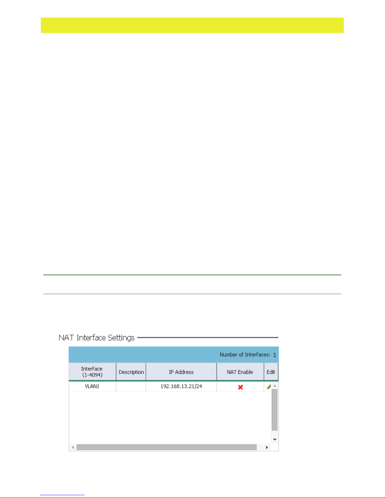
3 The NAT Interface Settings section displays the following NAT information:
Interface
Description
Displays the VLAN interface (1-4094) for each entry.
Displays the description configured each NAT entry configured in the
Configuration > Access Points edit screen.
Page 40

WiNG Express Version 5.8.2 Users Guide 40
IP Address
NAT Enable
Displays the IP Address for each configured NAT interface.
Displays if the Network Address Translation (NAT) is enabled on the
selected LAN interface. NAT converts an IP address in one network to a
different IP address or set of IP addresses in another network. The Access
Point's router maps its local (Inside) network addresses to WAN (Outside)
IP addresses and translates the WAN IP addresses on incoming packets to
local IP addresses. NAT is useful because it allows the authentication of
incoming and outgoing requests, and minimizes the number of WAN IP
addresses needed when a range of local IP addresses is mapped to each
WAN IP address.
Page 41

WiNG Express Version 5.8.2 Users Guide 41
Wireless
A Wireless Local Area Network (WLAN) is a data-communications system and wireless local
area network that flexibly extends the functionalities of a wired LAN. A WLAN links two or more
devices using spread-spectrum or OFDM modulation based technology. A WLAN does not
require lining up devices for line-of-sight transmission, and are thus, desirable for wireless
networking. Roaming users can be handed off from one wireless controller connected Access
Point to another, like a cellular phone system. WLANs can therefore be configured around the
needs of specific user groups, even when they are not in physical proximity.
WLANs are mapped to radios on each connected Access Point. A WLAN can be advertised from
a single Access Point radio or can span multiple Access Points and radios. WLAN configurations
can be defined to only provided service to specific areas of a site. For example, a guest access
WLAN may only be mapped to a 2.4GHz radio in a lobby or conference room providing limited
coverage, while a data WLAN is mapped to all 2.4GHz and 5GHz radios at the branch site
providing complete coverage.
Periodically refer to the Wireless screen to monitor an Access Point's WLAN utilization and
whether WLAN usage is consistent with an Access Point's deployment objective and the security
needs of its connected clients.
To configure WLAN properties to be complimentary with Access Point deployment objectives
and client support needs:
1 Select Configuration settings from the main menu then select Wireless.
The Wireless screen is partitioned into Radio Settings, Wireless LAN, Smart RF and
MeshConnex fields.
Page 42

WiNG Express Version 5.8.2 Users Guide 42
Note: Changes made to an Access Point's Configuration are pushed (provisioned) to up to 24
managed Access Points of the same model.
2 Configure the following Radio Settings for the 2.4Ghz and 5Ghz radios on the Access Point:
Channel
Use the drop-down menu to select a channel for the 2.4Ghz or 5Ghz radio.
To enable automatic channel selection based on RF conditions, select
Smart from the drop-down menu. The channels available for configuration
are channels for which the product is approved in its selected country. The
professional installer must ensure the product is set to operate under
conditions, and on channels, approved by country regulations.
Power
Specify a radio power for the 2.4Ghz or 5Ghz radio or select Smart to let
the Access Point manage the power settings based on network conditions.
Selecting Smart as the Power setting automatically configures radio power
to not exceed the maximum power allowed by the defined country. For
static power settings, the professional installer must ensure the configured
power levels are compliant with local and regional regulations. The county
selected automatically limits the maximum output power that can be set.
Data Rate
Use the drop-down menu to specify the data transmission rate used for the
transmission of probe responses. Options are specific to each device model
and radio type but may include, default, 11bgn(802.11b/g/n),
11gn(802.11g/n), 11n(802.11n), 11an(802.11a/n), 11anac(802.11a/n/ac)
and 11nac(802.11n/ac).
3 To add a new WLAN select +Add, to edit an existing WLAN, click the name of the WLAN. To
remove an existing WLAN highlight it and select Delete.
Page 43

WiNG Express Version 5.8.2 Users Guide 43
The Wireless LAN edit screen displays.
4 In the Wireless LAN section specify the following information for each managed WLAN:
Name
Add or edit a name for the WLAN. This name is used throughout the user
interface as a network identifier.
Enable
Displays a green check mark if the WLAN (and all its unique configuration
attributes) is enabled for Access Point utilization and a red X if the WLAN is
disabled.
SSID
Specify the WLAN's SSID. The WLAN SSID is case sensitive and
alphanumeric. SSID length should not exceed 32 characters.
Hide
Client-To-Client
Communications
Select this option to disable broadcast of the SSID used by this WLAN.
Select this option to enable client message exchanges within this WLAN.
The default is enabled, meaning clients are allowed to exchange packets
with other clients. It does not necessarily prevent clients on other WLANs
from sending packets to this WLAN, but as long as this setting also
disabled on that WLAN, clients are not permitted to interoperate.
Band
Select 2.4Ghz or 5Ghz (or both) to specify radio band support for the an
Access Point's requesting clients on this WLAN.
Page 44

WiNG Express Version 5.8.2 Users Guide 44
VLAN
Description
Security
Use the spinner control to specify a VLAN from 1 - 4,094 for this WLAN.
When a client associates with a WLAN, the client is assigned a VLAN by
load balance distribution. Do not use VLAN 1 with the WLAN if the WAN
port has been enabled.
Optionally, enter descriptive text which can be used by administrators to
help identify each WLAN.
Displays the WLAN Authentication type. Authentication is enabled per
WLAN to verify the identity of both users and devices. Authentication is a
challenge and response procedure for validating user credentials such as
username, password and sometimes secret-key information.
The screen displays with the Open option selected. Naming and saving
such a policy (as is) would provide no security and might only make sense
in a network wherein no sensitive data is either transmitted or received.
This default setting is not recommended.
If selecting Secure-PSK, select an encryption type for the WLAN. Define
whether the key is entered in ASCII or HEX characters. Selecting Show to
expose the key is not recommended.
If selecting Secure-802.1x, provide an IP address (or hostname) and a
shared secret (password) used to access an external RADIUS server
resource designated to validate user requests to the Access Point’s WLAN
resources.
Selecting Guest displays fields for captive portal Web page creation, and is
beyond the scope of this basic Access Point configuration.
Page 45

WiNG Express Version 5.8.2 Users Guide 45
Encryption
(Secure-PSK only)
When Secure-PSK security is selected, use the drop-down menu to select
an encryption type. Available encryption types include:
WEP-64 - Wired Equivalent Privacy (WEP) is a security protocol specified
in the Wi-Fi) standard. WEP is designed to provide a WLAN with a level of
security and privacy comparable to that of a wired LAN. WEP can be used
with open, shared, MAC and 802.1 X EAP authentications. WEP is optimal
for WLANs supporting legacy deployments when also used with 802.1X
EAP authentication to provide user and device authentication and dynamic
WEP key derivation and periodic key rotation. 802.1X provides
authentication for devices and also reduces the risk of a single WEP key
being deciphered. If 802.1X support is not available on the legacy device,
MAC authentication should be enabled to provide device level
authentication. WEP 64 uses a 40 bit key concatenated with a 24-bit
initialization vector (IV) to form the RC4 traffic key. WEP 64 is a less robust
encryption scheme than WEP 128 (containing a shorter WEP algorithm for
a hacker to potentially duplicate), but networks that require more security
are at risk from a WEP flaw. WEP is only recommended when clients are
incapable of using more robust forms of security. The existing 802.11
standard alone offers administrators no effective method to update keys.
WEP-128 - WEP 128 uses a 104 bit key which is concatenated with a 24-bit
initialization vector (IV) to form the RC4 traffic key. WEP may be all a small-
business user needs for the simple encryption of wireless data. However,
networks that require more security are at risk from a WEP flaw. WEP is
only recommended if there are client devices incapable of using higher
forms of security. The existing 802.11 standard alone offers administrators
no effective method to update keys. WEP 128 provides a more robust
encryption algorithm than WEP 64 by requiring a longer key length and
pass key. Thus, making it harder to hack through the replication of WEP
keys.
TKIP-CCMP - CCMP is a security standard used by the Advanced
Encryption Standard (AES). AES serves the same function TKIP does for
WPA-TKIP. CCMP computes a Message Integrity Check (MIC) using the
proven Cipher Block Chaining (CBC) technique. Changing just one bit in a
message produces a totally different result. The encryption method is
Temporal Key Integrity Protocol (TKIP). TKIP addresses WEP's
weaknesses with a re-keying mechanism, a per-packet mixing function, a
message integrity check and an extended initialization vector. However,
TKIP also has vulnerabilities.
WPA2-CCMP - WPA2 is a 802.11i standard that provides even stronger
wireless security than Wi-Fi Protected Access (WPA) and WEP. CCMP is
the security standard used by the Advanced Encryption Standard (AES).
AES serves the same function TKIP does for WPA-TKIP. CCMP computes
a Message Integrity Check (MIC) using the proven Cipher Block Chaining
(CBC) technique. Changing just one bit in a message produces a totally
different result. WPA2/CCMP is based on the concept of a Robust Security
Network (RSN), which defines a hierarchy of keys with a limited lifetime
(similar to TKIP). Like TKIP, the keys the administrator provides are used to
derive other keys. Messages are encrypted using a 128-bit secret key and
a 128-bit block of data. The end result is an encryption scheme as secure
as any a controller, service platform or Access Point provides for its
connected clients.
Page 46

WiNG Express Version 5.8.2 Users Guide 46
Key (Secure-PSK
only)
RADIUS VLAN
Assignment
(Secure-802.1x and
Guest only)
Bypass Captive
Portal Detection
When Secure-PSK security is selected, enter an encryption key. For WEP64 and WEP-128 enter a 4 to 32 character Pass Key and click the
Generate button. The pass key can be any alphanumeric string.
Controllers, service platforms, Access Points and their connected clients
use the algorithm to convert an ASCII string to the same hexadecimal
number. Clients without adapters need to use WEP keys manually
configured as hexadecimal numbers. For TKIP-CCMP and WPA2-CCMP
enter either an alphanumeric string of 8 to 63 ASCII characters or 64 HEX
characters as the primary string both transmitting and receiving
authenticators must share. The alphanumeric string allows character
spaces. The string is converted to a numeric value. This passphrase saves
the administrator from entering the 256-bit key each time keys are
generated.
Select this option to enable the RADIUS server to assign a VLAN post
authentication. Once a captive portal user is authenticated, the user is
assigned the VLAN configured in this field.
Refer to the Bypass field to enable or disable Bypass Captive Portal
Detection capabilities. If enabled, captive portal detection requests are
bypassed. This feature is disabled by default.
RADIUS (only
Secure-802.1x)
Only Internet
Access
Use DHCP/NAT on
APs
Bypass Captive
Portal Detection
Configure the RADIUS server to use for authentication. Select from
Local - Select this option to use the onboard RADIUS server.
Controller - Select this option to use the RADIUS server on the adopting
controller.
External - Select this option to configure details about an external RADIUS
server. Provide the primary server's IP address or hostname and the secret
shared with the server. Optionally provide the secondary server's IP
address or hostname and the secret shared with the server.
Select this option to prevent client devices from accessing resources on the
VLAN. This option restricts the clients to locations on the Internet only.
Select this option to use DHCP information as provided by the Access
Points. When selected, provide a DNS server IP for name resolutions.
When selected, the Client-To-Client Communication option is not available
and the VLAN is defaulted to VLAN 2200.
Select this option to enable Social Media Authentication to work on handheld devices. Using social media, a requesting client’s user credentials
require authentication through social media credential exchange and
validation.
Page 47

WiNG Express Version 5.8.2 Users Guide 47
Access Type
Select the authentication scheme applied to clients requesting captive
portal guest access to the WiNG network. Within the WiNG UI there’s 6
options. The WiNG CLI uses 5 options. User interface options include:
No authentication required - Requesting clients are redirected to the captive
portal Welcome page without authentication.
RADIUS Authentication - A requesting client’s user credentials require
authentication before access to the captive portal is permitted. This is the
default setting.
Registration - A requesting client’s user credentials require authentication
through social media credential exchange and validation.
Email Access - Clients use E-mail username and passwords for
authenticating their captive portal session. Optionally set whether E-mail
access requests are RADIUS validated.
Mobile Access - Mobile clients use their device’s access permissions for
authenticating their captive portal session. Optionally set whether mobile
access requests are RADIUS validated.
Other Access - Requesting guest clients use a different means of captive
portal session access (aside from E-mail or mobile device permissions).
Optionally set whether these other access requests are RADIUS validated.
Lookup
Information
When Other Access is selected as the access type, provide a 1-32
character lookup information string used as a customized authentication
mechanism.
Registration Type
Use the Registration Type drop-down menu to set the self-registration type
for tis selected WLAN. Options include Device, User and Device-OTP.
When captive portal guest users are authenticating using their User ID
(Email Address/Mobile Number/ Member ID) and the received pass code in
order to complete the registration process. The WLAN authentication type
should be MAC-Authentication and the WLAN registration type should be
configured as device-OTP.
When captive portal device registration is through social media, the WLAN
registration type should be set as device registration, and the captive portal
needs to be configured for guest user social authentication.
Radius Group
Use this field to provide a name for the default RADIUS group to which
each authenticated guest user will become a member of.
Session Timeout
(Guest Only)
Configure the session timeout value for Guest User access. This is the time
duration after which the guest user is forced to re authenticate.
5 In the WLAN Rate Limit section configure the following settings:
Page 48

WiNG Express Version 5.8.2 Users Guide 48
Enable (Per-Client)
Select this option to enable WLAN Rate limiting on a per client basis. Once
enabled configure the value in the per-client field.
Per-Client
If per-client WLAN rate limiting is enabled, use the spinner controls to
configure the per-client data rate limit between 50 to 1,000,000 kbps. The
client's maximum data speed is limited the configured rate.
Enable
(Aggregate WLAN)
Aggregate (WLAN)
Select this option to enable WLAN Rate limiting for the WLAN as a whole.
Once enabled configure the value in the aggregate field.
If aggregate WLAN rate limiting is enabled, use the spinner controls to
configure the WLAN aggregate data rate limit between 50 -1,000,000 kbps.
The collective data rate for all clients on the WLAN is limited to the
configured rate.
6 In the Other Settings section configure the following settings:
Client Roam Assist
Select this option to enable client roam assist. By monitoring a client's
packets and the received signal strength indicator (RSSI) of a given client,
decisions can be made on the optimal Access Point to which the client
needs to roam. Then forcefully direct the client to the optimal Access Point.
Voice VLAN
Select this option to enable a dedicated voice VLAN for the WLAN. If
enabled voice traffic will be tagged with with this VLAN.
7 To view and configure mesh wireless settings select the Smart-RF tab.
8 Configure the following Smart-RF settings for the WLAN:
Page 49

WiNG Express Version 5.8.2 Users Guide 49
Power Settings
2.4 GHz / 5 GHz
Filter DFS
Allowed Channel List
Specify the minimum and maximum power levels, between 1 and 20
dBm, for both the 2.4 GHz and the 5 GHz radios.
Select this option to filter channels used for DFS scanning for RADAR.
Selecting this option enables dynamic update of a channel list for the
mesh point on the 2.4 GHz and 5 GHz radios.To add an allowed
channel, select it from the drop-down menu and click the green + sign.
To remove a channel, select it from the list and click the red trashcan.
To add all channels to the allowed list, select All then select the green +
sign.
Channel Width
2.4 GHz / 5 GHz
Use the drop-down menu to specify the channel width in Smart RF
scans. Specify the channel width for both 2.4 GHz and 5 GHz traffic if
applicable.
Filter DFS
Client Aware
Scanning
Select this option to filter channels used for DFS scanning for RADAR.
Select this option to enable client aware scanning on the channel
specified. Enable for both 2.4 GHz and 5 GHz traffic if applicable.
2.4 GHz / 5 GHz
Voice Aware
Scanning
Select this option to enable voice aware scanning for voice traffic during
scans. Enable for both 2.4 GHz and 5 GHz traffic if applicable.
2.4 GHz / 5 GHz
9 Select the MeshConnex tab to view and configure mesh wireless settings.
Page 50

WiNG Express Version 5.8.2 Users Guide 50
Name
Displays the names of configured mesh points (mesh dedicated Access
Points).
Enable
Specifies the status of each configured mesh point, either Enabled or
Disabled.
Mesh ID
Control VLAN
Displays the IDs (mesh identifiers) assigned to mesh points.
Displays the VLAN (virtual interface ID) for the control VLAN on each of
the configured mesh points.
Allowed VLANs
Displays the list of VLANs allowed on each of the configured mesh
points.
Security Mode
Displays the security for each of the configured mesh points. The field
will display None for no security or PSK for pre-shared key
authentication.
To add a mesh point, select +Add and configure the following:
Name
Specify a name for the new mesh point. The name should be descriptive
to easily differentiate it from other mesh points. This field is mandatory.
Enable
Toggles the status of a mesh point on or off. To enable a mesh point,
select this option.
Mesh ID
Specify a mesh identifier for this mesh point. This field is optional.
Page 51

WiNG Express Version 5.8.2 Users Guide 51
Security
Allowed VLANs
Radio Bands
Allowed Channel List
Select a security authentication mode for the mesh point. Select none to
have no authentication for the mesh point. Select PSK to set a preshared key as the authentication for the mesh-point. If PSK is selected
enter a pre-shared key in the Key Settings section below. Select EAP to
use 802.1X EAP. The certificate should be issued from an Enterprise or
public certificate authority to allow 802.1X clients to validate the identity
of the authentication server prior to forwarding credentials.
Specify the VLANs allowed to pass traffic on the mesh point. Separate
all VLANs with a comma. To specify a range of allowed VLANs separate
the starting VLAN and the ending VLAN with a hyphen.
Select to enable 2.4 GHz and 5.0 GHz radio bands for the mesh point.
Unselecting a radio band will disable it for the mesh point.
Selecting this option enables a mesh point channel list dynamic update
on the 2.4 GHz and 5 GHz radios. To add an allowed channel, select it
from the drop-down menu and click the green + sign. To remove a
channel, select it from the list and click the red trashcan icon. To add all
channels to the allowed list, select All then select the green + sign.
Security
When protecting wireless traffic to and from a managed Access Point, an administrator should
not lose sight of the security solution in its entirety, since the chain is as weak as its weakest link.
The system provides seamless data protection and user validation to protect and secure data at
each vulnerable point in the Access Point managed network. Access Points support a Layer 2
wired/wireless firewall and Wireless Intrusion Protection System (WIPS) capabilities, while
additionally strengthened with a premium multi-vendor overlay security solution from Air Defense
with 24x7 dedicated protection. This security is offered at the most granular level, with role,
location and device categorization based network access control available to users based on
identity as well as the security posture of the client device.
Page 52

WiNG Express Version 5.8.2 Users Guide 52
Firewall
A firewall is a mechanism enforcing network access control, and is considered a first line of
defense in protecting proprietary information within the Access Point managed network. The
means by which this is accomplished varies, but in principle, a firewall can be thought of as
mechanisms both blocking and permitting data traffic within the network. Firewalls implement
uniquely defined access control policies, so if you don't have an idea of what kind of access to
allow or deny, a firewall is of little value, and in fact could provide a false sense of network
security.
With supported Access Points, firewalls are configured to protect against unauthenticated logins
from outside the network. This helps prevent hackers from accessing an Access Point's
managed wireless clients. Well-designed firewalls block traffic from outside the network, but
permit authorized users to communicate freely with ouside the network. All messages entering or
leaving an Access Point pass through the firewall, which examines each message and blocks
those not meeting the security criteria (rules) defined.
Firewall rules define the traffic permitted or denied within the network. Rules are processed by a
firewall supported device from first to last. When a rule matches the network traffic a controller or
service platform is processing, the firewall uses that rule's action to determine whether traffic is
allowed or denied.
Rules comprise conditions and actions. A condition describes a traffic stream of packets. Define
constraints on the source and destination device, the service (for example, protocols and ports),
and the incoming interface. An action describes what should occur to packets matching the
conditions set. For example, if the packet stream meets all conditions, traffic is permitted,
authenticated and sent to the destination device.
To configure Firewall rules:
1 Select Configuration from the main menu. Select Security, then Firewall.
Page 53

WiNG Express Version 5.8.2 Users Guide 53
The firewall screen is divided into WLAN ACL Rules and Wireless Client Association ACL
Rules fields.
Note: Changes made to an Access Point's configuration are pushed (provisioned) to up to 24
managed Access Points of the same model.
2 Set the following WLAN ACL Rules:
Precedence
Enabled
Action
Source IP
Destination IP
Specify or modify a precedence for this IP policy between 1-5000. Rules
with lower precedence are always applied to packets first. If modifying a
precedence to apply a higher integer, it will move down the table to reflect
its lower priority.
Select a firewall rule’s Enable or Disable icon to determine this rule’s
inclusion with the IP firewall policy.
Every IP firewall rule is made up of matching criteria rules. The action
defines what to do with a packet if it matches the specified criteria. The
following actions are supported:
Deny - Instructs the firewall to stop a packet from its destination.
Permit - Instructs the firewall to allow a packet to proceed to its destination.
Determine whether filtered packet source for this IP firewall rule require any
classification (any), are designated as a set of configurations consisting of
protocol and port mappings (an alias), set as a numeric IP address (host) or
defined as network IP and mask.
Determine whether filtered packet destinations for this IP firewall rule do not
require any classification (any), are designated as a set of configurations
consisting of protocol and port mappings (an alias), are set as a numeric IP
address (host) or defined as network IP and mask. Selecting alias requires
a destination network group alias be available or created.
Protocol
Define the access protocols impacted by the WLAN's ACL rule
configuration.
Direction
Interface
Specify the direction for ACL rule.
Specify the interface for the WLAN ACL rule to affect.
3 Set the following Wireless Client Association ACL Rules:
Precedence
Specify or modify a precedence for this IP policy between 1-5000. Rules
with lower precedence are always applied to packets first. If modifying a
precedence to apply a higher integer, it will move down the table to reflect
its lower priority.
Page 54

WiNG Express Version 5.8.2 Users Guide 54
Action
Start MAC
End MAC
Interface
Every IP firewall rule is made up of matching criteria rules. The action
defines what to do with the packet if it matches the specified criteria. The
following actions are supported:
Deny - Instructs the firewall to stop a packet from its destination.
Permit - Instructs the firewall to allow a packet to proceed to its destination.
Specify the source MAC address or network group configuration used as
basic matching criteria for this ACL rule. The source MAC ensures only an
authenticated endpoint is allowed to send traffic.
Specify the destination MAC address or network group configuration used
as basic matching criteria for this ACL rule. The end MAC represents the
destination MAC address of the packet examined for matching purposes
and potential device exclusion.
Use the drop-down menu to specify the interface configurations impacted
by the ACL's rule configuration.
Page 55

WiNG Express Version 5.8.2 Users Guide 55
WIPS
Access Points can utilize the Wireless Intrusion Protection Systems (WIPS) to provide
continuous protection against wireless threats and act as an additional layer of security
complementing wireless VPNs and encryption and authentication policies. WIPS is supported
through dedicated sensor devices designed to actively detect and locate unauthorized Access
Points. Upon detection, they use mitigation techniques to block the devices by manual
termination or air lock down.
Unauthorized APs are untrusted Access Points connected to a LAN accepting client
associations. They can be deployed for illegal wireless access to a corporate network, implanted
with malicious intent by an attacker, or could just be misconfigured Access Points that do not
adhere to corporate policies. An attacker can install an unauthorized AP with the same ESSID as
the authorized WLAN, causing a nearby client to associate to it. The unauthorized AP can then
steal user credentials from the client, launch a man-in-the middle attack or assume control of
wireless clients to launch denial-of-service attacks.
Access Points support unauthorized AP detection, location and containment natively. A WIPS
server can alternatively be deployed (in conjunction with the Access Point) as a dedicated
solution within a separate enclosure. When used within a managed network and its associated
Access Point radios, a WIPS deployment provides the following enterprise class security
management features and functionality:
♦ Threat Detection - Threat detection is central to a wireless security solution. Threat detection
must be robust enough to correctly detect threats and swiftly help protect the Access Point
managed wireless network.
♦ Rogue Detection and Segregation - A WIPS supported Access Point distinguishes itself by
both identifying and categorizing nearby Access Points. WIPS identifies threatening versus
non-threatening Access Points by segregating Access Points attached to the network
(unauthorized APs) from those not attached to the network (neighboring Access Points). The
correct classification of potential threats is critical for administrators to act promptly against
rogues and not invest in a manual search of neighboring Access Points to isolate the few
attached to the network.
To configure Wireless IPS on a managed Access Point:
1 Select Configuration from the main menu. Select Security, then Wireless IPS.
Page 56

WiNG Express Version 5.8.2 Users Guide 56
2 Select Enable Rogue AP Detection to allow the detection of unauthorized (unsanctioned)
devices from this WIPS policy.
3 Select Off-Channel Scan to scan across all channels using this Access Point's radio.
Channel scans use Access Point resources and can be time consuming, so only enable
when sure radio bandwidth can be dedicated to the channel scan and does not negatively
impact client support.
Note: Changes made to an Access Point's configuration are pushed (provisioned) to up to 24
managed Access Points of the same model.
4 Review the following Wireless IPS event information:
Unsanctioned AP
MAC
Displays the hardware encoded MAC address of each listed Access Point.
The MAC address is set at the factory and cannot be modified via the
management software.
Channel
Is Rogue
Displays the channel where the unsanctioned AP was detected.
Displays whether the detected device has been classified as a rogue
device, whose detection threatens the interoperation of connected devices.
SSID
Displays the Service Set ID (SSID) of the network to which the detected
Access Point belongs.
RSSI
Displays the Received Signal Strength Indicator (RSSI) of the detected
Access Point. Use this variable to help determine whether a device
connection would improve network coverage or add noise.
Page 57

WiNG Express Version 5.8.2 Users Guide 57
Reporter AP Name
Displays the hardware encoded Media Access Control (MAC) address of
the Access Point reporting the listed WIPS event.
Application Visibility
Deep packet inspection (DPI) is an advanced packet filtering technique functioning at the
application layer. Use DPI to find, identify, classify, reroute or block packets containing specific
data or codes that other packet filtering techniques (examining only packet headers) cannot
detect.
Enable DPI to scan data packets passing through the WiNG managed network. The contents of
each packet are scanned, occasionally logged and blocked or routed to their destination. Deep
packet inspection helps an ISP block the spread of viruses, illegal downloads and prioritize data
transmitted by bandwidth-heavy applications (video and VoIP applications) to help prevent
network congestion.
To configure Application Visibility on a managed Access Point:
1 Select Configuration from the main menu. Select Security, then Application Visibility.
The Application Visibility (AVC) screen is divided into WLAN Application Rules and
WLAN Application Schedule Rules.
2 Create new WLAN Application Rules by selecting + Add Rule and configuring the following
fields.
Page 58

WiNG Express Version 5.8.2 Users Guide 58
Precedence
Action
Category
Application
Schedule Policy
Mark Type
Mark Value
Set the priority (from 1 - 256) for the application policy rule. The lower the
value, the higher the priority assigned to this rule’s enforcement action and
the category and application assigned. A precedence also helps resolve
conflicting rules for applications and categories.
Set the action executed on the selected application category and
application. The default setting is Allow.
Select the category for which the application rule applies. Selecting All
auto-selectes All within the Application table.
Select All from the Application table to list all application category statistics,
or specify a particular category name to display its statistics only.
Select a schedule policy from the drop-down menu. If a schedule policy
does not exist, create one in the Scheduler section.
Mark actions mark packets for a recognized application and category with
DSCP/8021p values used for QoS.
Displays the DSCP/8021p application or category value associated with
each WLAN application rule.
Ingress Rate
Specify an ingress (incoming traffic) rate for the rate-limiter for this
application rule.
Egress Rate
Specify an egress (outgoing traffic) rate for the rate-limiter for this
application rule.
WLAN
Specify the WLAN which to apply the application rules.
3 To delete an existing rule, select that rule from the table and select Delete Rule.
4 Create new WLAN Application Schedule Rules by selecting + Add Schedule and
configure the following fields.
Days
Start Time
End Time
WLAN
5 To delete and existing schedule select that rule from the table and select Delete Schedule.
Specify the number of days the application rule should be applied.
Specify a starting date and time for the application rule to start.
Specify an end date and time for the application rule to stop.
Specify the WLAN which to apply the application rules to.
Page 59

WiNG Express Version 5.8.2 Users Guide 59
Schedule Policy
To configure a Schedule Policy for a managed Access Point:
1 Select Configuration from the main menu. Select Security, then Schedule Policy.
2 Create a new Schedule Policy by selecting + Add Policy and configure the following:
Name
Description
Schedule Rules
Provide a name for the new schedule policy.
Optionally, provide a description for the schedule policy.
Create one or more schedule rules by selecting + Add and specify the Days
of the week as well as Start and End Times.
3 To delete and existing schedule select that rule from the table and select Delete Policy.
Page 60

WiNG Express Version 5.8.2 Users Guide 60
Services
DHCP
DHCP is a protocol that includes mechanisms for IP address allocation and delivery of hostspecific configuration parameters from a DHCP server to a host. Some of these parameters are
IP address, network mask, and gateway. The WAN and LAN ports should not both be configured
as DHCP.
To configure DHCP Services:
1 Select Configuration from the main menu. Select Services.
The DHCP Settings screen displays.
2 Select Enable DHCP Server to assign IP addresses to requesting wireless clients.
Enabling DHCP allows the Access Point's onboard DHCP server resource to provide IP and
DNS information to requesting clients on the LAN interface.
3 If the DHCP server is enabled, configure the following settings:
Page 61

WiNG Express Version 5.8.2 Users Guide 61
Interface
IP
Default Gateway
Use the drop-down menu to select an interface for the DHCP server.
Supported Access Points have the following interface availability:
AP6511 - FE1, FE2, FE3, FE4, UP1
AP6521 - GE1/POE (LAN)
AP6522 - GE1/POE (LAN)
AP6562 - GE1/POE (LAN)
AP7502 - GE1, FE1, FE2, FE3
AP7522E - GE1/POE (LAN)
Specify the IP mask for each entry in the DHCP server. Applying a subnet
mask to an IP address separates the address into a host address and an
extended network address. Subnets can improve network security and
performance by organizing hosts into logical groups.
Enter the IP address of the network's default gateway. A default gateway
provides an entry/exit point for the network as it commonly connects an
internal network to an external network.
Primary DNS
Secondary DNS
Start IP
End IP
Lease Time (days)
Lease Time (hours)
Enter an IP Address for the main DNS server resource for the Access
Point's WAN interface.
Enter an IP Address for the backup (secondary) Domain Name Server
providing DNS services for the Access Point's WAN interface.
Enter the starting IP Address for each DHCP address pool range
configured. Ensure the range is large enough to meet the needs of
requesting clients.
Enter the ending IP Address for each DHCP address pool range
configured. Ensure the range is large enough to meet the needs of
requesting clients.
If a lease time has been defined for a listed network pool, it displays in
days. DHCP leases provide addresses for defined times to requesting
clients. If a client does not use the leased address for the defined time, that
IP address can be re-assigned to another requesting DHCP client.
If a lease time has been defined for a listed network pool, it displays in
hours. DHCP leases provide addresses for defined times to requesting
clients. If a client does not use the leased address for the defined time, that
IP address can be re-assigned to another requesting DHCP client.
Lease Time
(minutes)
If a lease time has been defined for a listed network pool, it displays in
minutes. DHCP leases provide addresses for defined times to requesting
clients. If a client does not use the leased address for the defined time, that
IP address can be re-assigned to another requesting DHCP client.
Page 62

WiNG Express Version 5.8.2 Users Guide 62
RADIUS
The Access Point's local RADIUS server allows the configuration of user groups with common
user policies. User group names and associated users are stored in the controller, service
platform or Access Point's local database. The user ID in the received access request is mapped
to the associated wireless group for authentication.
To view RADIUS configurations:
1 Select Configuration tab from the main menu.
2 Select the Services tab from the Configuration menu.
The upper pane of the user interface displays the DHCP and RADIUS options.
3 Select RADIUS.
4 Select Enable Radius Server to activate the internal RADIUS server.
5 Select Start Radius Server to start the RADIUS service on the AP.
6 Review the following RADIUS group configuration information. To create a new RADIUS
group click + Add. To remove an existing group or groups, select them from the table and
click Delete.
RADIUS Group
Displays the group name or identifier assigned to each listed group when it
was created. The name cannot exceed 32 characters or be modified as
part of the group edit process.
Guest User Group
Select to enable RADIUS access to the guest user group with the settings
outlined in this section.
Page 63

WiNG Express Version 5.8.2 Users Guide 63
VLAN
Displays the VLAN ID used by the group. The VLAN ID is representative of
the shared SSID each group member (user) employs to interoperate within
the network (once authenticated by the local RADIUS server).
WLAN SSID
Displays the Service Set ID (SSID) of the network the Access Point belongs
to. Select All to add all SSIDs to the table. To add individual SSIDs, select
them from the drop-down menu and select the green + sign. To remove
SSIDs from the table, select one or more SSID and select the red trashcan.
Rate limit from air
Specify the maximum data rate in kbps between 100 and 1,000,000 for
traffic originating on the wireless network.
Rate limit to air
Specify the maximum data rate in kbps between 100 and 1,000,000 for
traffic destined for the wireless network.
Inactivity Timeout
Specify a time limit, in seconds, before the guest user group is
automatically timed out. If the user or group times out they must
reauthenticate with the RADIUS server.
7 Review the following RADIUS schedule information and modify as needed:
Access by time
To enable restricted guest access to the RADIUS server by time of day,
select this option and then specify a Start Time and End Time in the fields
below.
Start Time
When Access by Time is enabled, specify the start time users within each
listed group can access local RADIUS resources.
End Time
When Access by Time is enabled, specify the end time users within each
listed group lose access to the local RADIUS resources.
Access by Day of
Week
To enable guest access to the RADIUS server by specific days of the week,
select this option and select each of the days you wish to enable access.
8 When adding or editing a RADIUS user, verify and configure the following:
User ID
Displays the name or identifier assigned to each user when created. The
name cannot exceed 32 characters or be modified as part of the edit
process.
Guest User
Group
Select to enable RADIUS access using the guest user group with this user.
Use the pull-down menu to select which group to associate with the
RADIUS user.
Email ID
Specify an E-mail address for the RADIUS user. This can be a local E-mail
address or a fully qualified E-mail address.
Telephone
Specify the telephone number associated with the RADIUS user. This is an
optional field.
Start Date / Start
Specify a start date and time when this RADIUS user is activated.
Time
Page 64

WiNG Express Version 5.8.2 Users Guide 64
Expiry Date /
Expiry Time
Access Duration
Specify an end date and time when this RADIUS user is deactivated.
Specify how long the RADIUS user is active by selecting an access
duration. To allow the use of the Expiry Date and Expiry Time fields select
the Til Expiry option. To specify a duration of time the account will be
active, specify a duration in Days:Hours:Minutes format. The RADIUS user
will be deactivated once the set duration has expired.
Page 65

WiNG Express Version 5.8.2 Users Guide 65
Management
Access Points have mechanisms to allow/deny access for separate interfaces and protocols
(HTTP, HTTPS, Telnet, SSH or SNMP). Management access can be enabled/disabled as
required for unique policies. This access functionality is not meant to function as an ACL (in
routers or other firewalls), where administrators specify and customize specific IPs to access
specific interfaces. It is rather a means of disabling unused interfaces to reduce network
vulnerabilities.
To enhance security, administrators can apply various restrictions as needed to:
♦ Restrict SNMP and Web UI access to specific hosts or subnets
♦ Disable un-used and insecure interfaces as required within managed access profiles.
Disabling un-used management services can dramatically reduce an attack footprint and free
resources on managed devices
♦ Provide authentication for management users
♦ Apply access restrictions and permissions to management users
Management restrictions should be applied to meet specific policies or industry requirements
requiring only certain devices or users be granted access to critical Access Point resources.
Management restrictions can also be applied to reduce the Access Point's attack footprint when
guest services are deployed.
To configure the Access Point's management settings:
1 Select Configuration settings from the main menu then select Management.
The Management screen is partitioned into Administrator, Access, Syslog Server, SNMP
Settings and SNMP Traps fields.
Page 66

WiNG Express Version 5.8.2 Users Guide 66
Note: Changes made to an Access Point's Configuration are pushed (provisioned) to up to 24
managed Access Points of the same model.
2 In the Administrator section, select Change User Password to change the default
administrator login password to something more proprietary and secure.
3 Set the following Access settings:
HTTP
Select the checkbox to enable HTTP device access. HTTP provides limited
authentication and no encryption.
HTTPS
Select the checkbox to enable HTTPS device access. HTTPS (Hypertext
Transfer Protocol Secure) is more secure than HTTP. HTTPS provides
both authentication and data encryption as opposed to just authentication
(as is the case with HTTP).
Telnet
Select the checkbox to enable Telnet device access. Telnet provides a
command line interface to a remote host over TCP. Telnet provides no
encryption, but does provide a measure of authentication. Telnet access is
disabled by default.
SSHv2
Select the checkbox to enable SSH device access. SSH (Secure Shell)
version 2, like Telnet, provides a command line interface to a remote host.
SSH transmissions are encrypted and authenticated, increasing the
security of transmission. SSH access is disabled by default.
4 In the Syslog Server section configure the following settings:
Logging
Select this option to log system events to a log file or a syslog server.
Selecting this option enables the rest of the parameters required to define
the Access Point's logging configuration. This option is disabled by default.
Logging Level
Event severity coincides with the syslog logging level defined for the
Access Point. Assign a numeric identifier to log events based on criticality.
Severity levels include:
0 - Emergency, 1 - Alert, 2 - Critical, 3 - Errors, 4 - Warning, 5 - Notice, 6 Info and 7 - Debug. The default logging level is 4.
Server IP
Enter the IP addresses where logged system events can be sent on behalf
of the event generating Access Point.
5 Set the following SNMP Settings:
Enable SNMPv1
SNMP v1 exposes a device's management data so it can be managed
remotely. Device data is exposed as variables accessed and modified as
text strings, with version 1 being the original (rudimentary) implementation.
SNMPv1 is disabled by default.
Enable SNMPv2
Select the checkbox to enable SNMPv2 support. SNMPv2 provides device
management using a hierarchical set of variables. SNMPv2 uses Get,
GetNext, and Set operations for data management. SNMPv2 is enabled by
default.
Page 67

WiNG Express Version 5.8.2 Users Guide 67
Enable SNMPv3
SNMP v1/v2
Community String:
Access Control
SNMPv3 Users:
User Name
SNMPv3 Users:
Password
Select the checkbox to enable SNMPv3 support. SNMPv3 adds security
and remote configuration capabilities to previous versions. The SNMPv3
architecture introduces the user-based security model (USM) for message
security and the view-based access control model (VACM) for access
control. The architecture supports the concurrent use of different security,
access control and message processing techniques. SNMPv3 is enabled
by default.
Set the access permission for each community string used to retrieve or
modify information. Available options include:
Read Only - Allows a remote device to retrieve information.
Read-Write - Allows a remote device to modify settings.
Use the drop-down menu to define a user name of snmpmanager,
snmpoperator or snmptrap.
Provide the user's password in the field provided. Select the Show check
box to display the actual character string used in the password. Leaving the
check box unselected protects the password and displays each character
as "*".
SNMPv3 Users:
Authentication
Select the user authentication type used with the listed SNMPv3 user. The
selected authentication scheme ensures only trusted users can utilize
Access Point network resources.
SNMPv3 Users:
Encryption
Select the encryption scheme used with the listed SNMPv3 user. The
selected encryption scheme ensures only trusted devices can utilize
Access Point network resources.
6 In the SNMP Traps section select + Add for each entry configure the following:
Trap Generation
Select the Trap Generation checkbox to enable trap generation using the
trap receiver configuration defined. This feature is disabled by default.
IP Address
Sets the IP address of an external server resource dedicated to receive
SNMP traps on behalf of the Access Point.
Port
Set the virtual port of the server resource dedicated to receiving SNMP
traps. The default port is port 162.
Version
7 To remove a trap highlight it in the table and select Delete.
Sets the SNMP version to send SNMP traps. SNMPv2c is the default.
Page 68

WiNG Express Version 5.8.2 Users Guide 68
Access Points
Use the Access Points screen to assess the configuration and network health of managed
Access Points. Individual Access Points can be selected and their configurations customized as
required to better support the deployment objective of the network.
To review Access Points:
1 Select Access Points from the main menu.
The Access Points screen displays information about managed Access Points.
2 The Managed Access Points section displays the following:
AP Name
AP Status
IP Address
2.4GHz Channel
Displays the administrator assigned Access Point name. Names can be
revised using the Edit menu.
Displays the active state of each listed Access Point. If an Access Point is
online, two green up arrows are displayed. If an Access Point is offline two
green down arrows display.
Displays the current IP Address assigned assigned to each Access Point as
its network identifier. IPv6 formatted IP addresses are not supported, and
the IP address is in an IPv4 format.
Displays the current radio channel number set for the 2.4 GHz radio on
each Access Point. AP6511 and AP6521 Access Points are single radio
models, the other supported Access Points are dual radio models.
Page 69

WiNG Express Version 5.8.2 Users Guide 69
2.4 GHz Power
Displays the 2.4 GHz radio's current power level in dBm. If using a dual
radio model Access Point, each radio should be configured with a unique
transmit power in respect to its intended client support function.
5 GHz Channel
Displays the current radio channel number for the 5 GHz radio, if
applicable, on each managed Access Point. AP6511 and AP6521 Access
Points are single radio models, and will not display channel information for
a second radio.
5 GHz Power
Displays the 5 GHz radio's current power level in dBm. If using a dual radio
model Access Point, each radio should be configured with a unique
transmit power in respect to its intended client support function.
Firmware
Displays the full firmware version number on each listed Access Point.
Periodically compare the Access Point's firmware version against the latest
version available on the Support site to help ensure the Access Point is
deployed with the most recent firmware, providing the most recent feature
set.
3 To access advanced Access Point options, select an AP or multiple APs from the Managed
Access Points section and select the Tools pull-down menu. The following tools are
available:
Factory-Default
Selecting Factory-Default displays a prompt confirming whether to reset
the device to factory defaults. Selecting Yes will reset the device to factory
default settings and will reboot the device. Choosing this option will erase
all information and settings stored on the device. Selecting No will cancel
the reset and return to the Access Point screen.
Reboot
Upgrade
Selecting Reboot displays a prompt confirming you want to reboot the
device. Selecting Yes will reboot the device and the user interface will be
unavailable until the device has rebooted. You will be required to log in to
the user interface once the devices has finished rebooting. Selecting No
will cancel the reboot and return you to the Access Point screen.
Seleting Upgrade displays the Device Upgrade page. If Basic is selected,
enter the URL for the upgrade firmware in the following format:
URL Syntax:
tftp://<hostname|IP>[:port]/path/file
ftp://<user>:<passwd>@<hostname|IP>[:port]/path/file
If Advanced is selected, configure the Protocol, Port, Hostname or IP
Address, Username, Password and the path for the firmware file.
Firmware upgrade is supported via FTP, TFTP and HTTP protocols.
Page 70

WiNG Express Version 5.8.2 Users Guide 70
Tech-Support
Export / Import
Config
Locator ON
Selecting Tech-Support displays the Copy Tech Support screen where
system information and logs can be transfered to technical support by
configuring the Protocol, Port, Hostname or IP Address, Username,
Password and the path for the tech support server. Transfer of this
information is supported via FTP, TFTP and HTTP protocols. The tech
support filename is auto generated by the device based on the device mac
address, passing file name in path results in failure.
Selecting Export / Import Config displays a screen where configuration
files can be imported or exported from the device. When Local is selected
the start-up system configuration file is displayed as plain text in a window.
To import a new configuration using this method, erase the contents of the
configuration window and paste the contents of a new configuration file
into the window. When all changes are complete, click the import button to
import the new configuration file onto the device. To export a configuration
file and Local is selected, simply copy the contents of the configuration
window and paste it into a text file on your local system. Configuration files
can also be imported from or exported to remote systems. Select Remote
and specify the Protocol, Port, Hostname or IP Address, Username,
Password and the path for the remote server. Transfer of this information
is supported via FTP, TFTP and HTTP protocols.
Selecting Locator ON will start flashing the LEDs of the device to make it
easier to find in large deployments.
Locator OFF
Delete Devices
Selecting Locator OFF will stop flashing the LEDs of the device if they
have been set to flash using the Locator ON option.
Use this option to delete offline APs from the managed system. The
Access Point must first be offline before it may be deleted.
Page 71

WiNG Express Version 5.8.2 Users Guide 71
4 To edit an Access Point's settings, click on the AP Name of the Access Point you wish to
edit.
5 Refer to the following device information in Basic Settings:
AP Name
Displays the unique name assigned to the Access Point. This name can be
changed on this screen or the Configuration > Basic screen.
Location
Version
Model
Up Time
Displays the location name configured on the Configuration > Basic screen.
Displays the currently active firmware version running on the Access Point.
Displays the device model number for the Access Point.
Displays the amount of time in days, hours and minutes since the last time
the device rebooted. Use this information to determine whether a newer
firmware version is available potentially providing an enhanced feature set.
MAC Address
Displays the hardware encoded MAC address of the Access Point. The
MAC address is set at the factory and cannot be modified via the
management software.
Default Gateway
Displays the default gateway information for the Access Point. A default
gateway provides an entry/exit point for the network as it commonly
connects an internal network to an external network. To override the default
gateway address specify a new IP address.
6 Configure the following options for Wireless Settings:
Page 72

WiNG Express Version 5.8.2 Users Guide 72
2.4 GHz Channel /
Power
Use the drop-down menu to select a channel for the 2.4GHz radio. AP6511
and AP6521 Access Points are single radio models. Set the transmit power
of the selected Access Point radio. If using a dual radio model Access
Point, each radio should be configured with a unique transmit power in
respect to its intended client support function. Select the Smart option to let
Smart RF determine the transmit power. A setting of 0 defines the radio as
using Smart RF to determine its output power. 0 dBm, Smart RF, is the
default value.
5 GHz Channel /
Power
If applicable, use the drop-down menu to select a channel for the Access
Point's 5GHz radio. All model Access Points support a second radio, with
the exception of single radio model AP6511 and AP6521 Access Points. If
using a dual radio model Access Point, each radio should be configured
with a unique transmit power in respect to its intended client support
function. Select the Smart option to let Smart RF determine the transmit
power. A setting of 0 defines the radio as using Smart RF to determine its
output power. 0 dBm, Smart RF, is the default value.
7 Select Enable RADIUS Server to enable the onboard RADIUS server. RADIUS settings can
be configured on the RADIUS Screen.
8 Optionally, from the IP Settings section Add, Edit or Delete LAN Settings for the Access
Point. When adding and editing settings specify the following:
Interface
Use the drop-down menu to select an Access Point interface to connect to
the network. Keep unused interfaces disabled to reduce network
vulnerabilities.
Description
Enter a description for each interface configured to distinguish it from other
devices with similar attributes.
IP Address
Enter or edit the IP Address associated with each interface. To edit the IP
Address click the edit icon next to the corresponding interface.
9 Optionally, from the DNS Servers section override DNS server settings for the Access Point.
When adding and editing DNS servers settings specify the following:
IP Address
Enter or edit the IP Address associated with each interface. To edit the IP
Address click the edit icon next to the corresponding server entry.
10 Optionally, from the Route section Add, Edit or Delete LAN Settings for the Access Point.
When adding and editing settings specify the following:
Network Address
Gateway
Specify the destination IP address and mask in the A.B.C.D/M format.
Optionally specify the default gateway IP address and mask, in the
A.B.C.D/M format, used to communicate with the main router. A default
gateway provides an entry/exit point for the network as it commonly
connects an internal network to an external network.
11 When all required settings are configured, click Apply to save the changes to the Access
Point configuration.
12 To return to the Access Points screen click << Go Back.
Page 73

EVENT HISTORY
Chapter 6
In This Chapter
Event History ............................................................. 73
Event History
The Event History screen displays historical events for managed Access Points. Events can be
filtered by using criteria in the search field.
To review the event history:
1 Select Event History from the main menu.
Page 74

WiNG Express Version 5.8.2 Users Guide 74
2 Review the following event data to determine the severity of specific events and the devices
reporting them:
Timestamp
Module
Message
Severity
Displays the timestamp (time zone specific) when the displayed event
message was generated. Use this information to help assess whether the
listed timestamp coincides with any known issue impacting the network.
Displays the Access Point module (resource) detecting, reporting and
tracking the event. Events detected by other modules are not tracked.
Displays error or status messages for each event listed. Use the message
text as an additional means of assessing an event's potential impact to the
managed Access Point.
Displays the severity of the event as defined for tracking from the
Configuration screen. Severity options include:
All Severities – All events are displayed irrespective of their severity
Critical – Only critical events are displayed
Error – Only errors and above are displayed
Warning – Only warnings and above are displayed
Informational – Only informational and above events are displayed
Source
Displays the hardware encoded MAC address of the source device tracked
by the selected module.
Hostname
Displays the administrator assigned name of the source device tracked by
the listed module.
3 Use the Search field as necessary to refine event history to specific criteria.
4 Select Clear All to erase the existing event logs.
5 Select Refresh to manually update the event history logs. If you have selected Stop select
refresh to re-enable automatic updating
6 Select Stop to stop automatic updating of the event history logs.
Page 75

CUSTOMER-SUPPORT
Support Center
If you have a problem with your equipment, contact support for your region. Support and issue
resolution is provided for products under warranty or that are covered by a services agreement.
Contact information and Web self-service is available by visiting www.zebra.com/support
When contacting support, please provide the following information:
♦ Serial number of the unit
♦ Model number or product name
♦ Software type and version number
Support responds to calls by email or telephone within the time limits set forth in support
agreements. If you purchased your product from a business partner, contact that business
partner for support.
Customer Support Web Site
The Support Web site, located at www.zebra.com/support provides information and online
assistance including developer tools, software downloads, product manuals, support contact
information and online repair requests.
Manuals
www.zebra.com/support
Page 76

Zebra Technologies Corporation
Lincolnshire, IL 60069 USA
Zebra and the Zebra head graphic are registered trademarks of ZIH Corp. The Symbol logo is a
registered trademark of Symbol Technologies, Inc. a Zebra Technologies company.
© 2015 Symbol Technologies, Inc.
MN-002676-01 Revision A December 2015
 Loading...