

VC80
M1M7M2M8M3M9M4
M10M5M11M6M12
Vehicle-Mount Computer
User Guide


VC80
USER GUIDE
MN002384A01
Rev. A
January 2016

ii VC80 User Guide
Revision History
Changes to the original guide are listed below:
Change Date Description
Rev A 01/2016 Initial release.

TABLE OF CONTENTS
Revision History ................................................................................................................................. ii
About This Guide
Introduction ....................................................................................................................................... vii
Configurations ........................................................................................................................................viii
Chapter Descriptions .............................................................................................................................. ix
Notational Conventions..................................................................................................................... ix
Related Documents and Software ........................................................................................................... x
Service Information ............................................................................................................................ x
Chapter 1: Getting Started
Introduction .................................................................................................................................... 1-1
Unpacking ...................................................................................................................................... 1-1
Removing the Protective Film from the Display ....................................................................... 1-1
Safety ............................................................................................................................................. 1-2
Initial Operation Safety Considerations .................................................................................... 1-2
Power Supply/Cable Safety ..................................................................................................... 1-2
External Devices Safety ........................................................................................................... 1-2
VC80 Vehicle-Mount Computer Features ...................................................................................... 1-3
Front Keys and LED Indicators ...................................................................................................... 1-5
Front Keys ................................................................................................................................ 1-5
LED Indicators .......................................................................................................................... 1-6
Configuring GPS ............................................................................................................................ 1-6
Connecting External Devices ......................................................................................................... 1-7
Powering Up the VC80 .................................................................................................................. 1-7
Powering Down the VC80 .............................................................................................................. 1-7
Setting Up WLAN ........................................................................................................................... 1-8
Connecting WLAN .................................................................................................................... 1-8
Setting Up a New Connection or Network ................................................................................ 1-9
Broadcom Help ...................................................................................................................... 1-10

iv VC80 User Guide
Chapter 2: Installation
Introduction .................................................................................................................................... 2-1
Overview ........................................................................................................................................ 2-1
Mounting Instructions ..................................................................................................................... 2-1
Heater Status ................................................................................................................................. 2-1
Installing the VC80 ......................................................................................................................... 2-2
Electrical Installation ................................................................................................................ 2-2
Wiring Guidelines ............................................................................................................... 2-3
Wiring Vehicle Power to the VC80 ........................................................................................... 2-4
Positioning the VC80 in the Vehicle ......................................................................................... 2-5
Overview of the Assembly Steps ............................................................................................. 2-5
Cable Dust Cover ..................................................................................................................... 2-5
Strain Relief .............................................................................................................................. 2-5
Installing the VC80 on a Forklift ............................................................................................... 2-6
Forklift Battery Replacement Conditions ........................................................................................ 2-7
Starting from Cold Soak ................................................................................................................. 2-7
Installing the Power Pre-Regulator ................................................................................................ 2-8
Non-Vehicle Installations ............................................................................................................... 2-8
Power On/Off with Ignition ............................................................................................................. 2-9
Screen Blanking Wiring ................................................................................................................ 2-10
Connecting Switch for Screen Blanking ................................................................................. 2-10
Chapter 3: Software
Introduction .................................................................................................................................... 3-1
Microsoft Windows Setup and Configuration ................................................................................. 3-1
Folder Structure ....................................................................................................................... 3-1
VC80 Software Components ......................................................................................................... 3-2
VC80 Without Operating System ................................................................................................... 3-2
Connecting to Terminal Emulation ................................................................................................. 3-3
TekTerm ................................................................................................................................... 3-3
Bar Code Scanners and Settings ................................................................................................... 3-4
Serial Scanners ........................................................................................................................ 3-4
USB Scanners .......................................................................................................................... 3-6
Bluetooth Scanners .................................................................................................................. 3-6
Pairing Bluetooth Scanners Using Bar Codes ................................................................... 3-6
Settings .......................................................................................................................................... 3-9
Quick Setup ..................................................................................................................
Touch Panel Calibration ................................................................................................... 3-11
Manage VC Configuration ................................................................................................ 3-16
Bezel Keyboard ...................................................................................................................... 3-17
Haptic Feedback .................................................................................................................... 3-18
Heater Status ......................................................................................................................... 3-19
Power ..................................................................................................................................... 3-20
Push To Talk .......................................................................................................................... 3-21
Screen Blanking ..................................................................................................................... 3-22
System Info ............................................................................................................................ 3-23
TekWedge .............................................................................................................................. 3-24
UPS Battery Status ................................................................................................................ 3-27
Data Logging .......................................................................................................................... 3-28
.......... 3-10

Table of Contents v
My-T-Soft ..................................................................................................................................... 3-29
Windows Management Instrumentation ....................................................................................... 3-31
GPS ............................................................................................................................................. 3-31
Satellite Level ......................................................................................................................... 3-32
Location Coordinates ............................................................................................................. 3-32
U-Center Software ................................................................................................................. 3-32
Chapter 4: Maintenance and Troubleshooting
Introduction .................................................................................................................................... 4-1
Cleaning ........................................................................................................................................ 4-1
Housing Cleaning ..................................................................................................................... 4-1
Touchscreen Cleaning ............................................................................................................. 4-1
Touchscreen .................................................................................................................................. 4-2
Troubleshooting ............................................................................................................................. 4-3
Chapter 5: Accessories and Mounting
Introduction .................................................................................................................................... 5-1
Accessories .................................................................................................................................... 5-1
External Bar Code Scanners ......................................................................................................... 5-5
VC80 Antenna Options .................................................................................................................. 5-6
VC80 Mounting Accessories .......................................................................................................... 5-7
MT43XX RAM Mount ............................................................................................................... 5-8
Optional Mounts ....................................................................................................................... 5-9
Plate Bases for MT35XX Mounts ....................................................................................... 5-9
MT4200 Quick Release Mount ............................................................................................... 5-10
Assembling MT4200 ........................................................................................................ 5-10
Attaching MT4200 to VC80 .............................................................................................. 5-11
MT4210 Adaptor Bracket ....................................................................................................... 5-12
Chapter 6: Scancode Map
Introduction .................................................................................................................................... 6-1
Integrated Keypad .......................................................................................................................... 6-2
Appendix A: Specifications
Introduction ................................................................................................................................... A-1
Technical Specifications ............................................................................................................... A-2
VC80 Drill Hole Dimensions .......................................................................................................... A-5

vi VC80 User Guide

ABOUT THIS GUIDE
Introduction
This guide provides instructions for setting up, operating, configuring, and maintaining the VC80 vehicle-mount
computer.
NOTE Screens and windows pictured in this guide are samples and can differ from actual screens.
WARNING! Before transporting, assembling, and starting the computer, please read this manual
carefully and follow all the safety guidelines and requirements.

viii VC80 User Guide
Configurations
The VC80 offers different configurations to suit various work requirements. Some of the configuration options
include:
•
Intel E3825 Dual Core, 1.33 GHz, 1 MB Cache, 2 GB RAM
•
Intel E3845 Quad Core, 1.91 GHz, 2 MB Cache, 4 GB RAM
•
SSD (32 GB or 64 GB)
•
Sunlight Readable Display
•
Internal Antenna
•
External Antenna
•
Freezer Condensing
•
Windows Embedded Standard 7
•
Windows 7 Professional for Embedded Systems
•
Basic I/O
•
CanBus
•
Ethernet
NOTE For detailed configuration and part number information, contact your Zebra representative.

About This Guide ix
Chapter Descriptions
Topics covered in this guide are as follows:
•
Chapter 1, Getting Started, provides information on safety guidelines and initial VC80 setup.
•
Chapter 2, Installation, provides instructions on installing the VC80.
•
Chapter 3, Software, explains how to configure the VC80.
•
Chapter 4, Maintenance and Troubleshooting, includes instructions on cleaning the VC80 and provides
troubleshooting solutions for potential problems during device operations.
•
Chapter 5, Accessories and Mounting, describes the accessories and mounting options available for the
VC80.
•
Chapter 6, Scancode Map, provides information on the integrated scancode maps for the VC80.
•
Appendix A, Specifications, summarizes the device’s intended operating environment and technical
specifications.
Notational Conventions
The following conventions are used in this document:
•
Italics are used to highlight the following:
• Chapters and sections in this guide
• Related documents.
•
Bold text is used to highlight the following:
• Dialog box, window and screen names
• Drop-down list and list box names
• Check box and radio button names
• Icons on a screen
• Key names on a keypad
• Button names on a screen.
•
Bullets (•) indicate:
• Action items
• Lists of alternatives
• Lists of required steps that are not necessarily sequential.
•
Sequential lists (e.g., those that describe step-by-step procedures) appear as numbered lists.

x VC80 User Guide
Related Documents and Software
The following document provides more information about the VC80 vehicle-mount computer.
•
VC80 Quick Reference Guide, p/n MN002383Axx - includes VC80 setup information and regulatory
information.
For the latest version of this guide and all guides, go to: http://www.zebra.com/support
Service Information
If you have a problem with your equipment, contact Zebra Customer Support for your region. Contact information is
available at: http://www.zebra.com/support
When contacting support, please have the following information available:
•
Serial number of the unit
•
Model number or product name
•
Software type and version number.
Zebra responds to calls by email, telephone or fax within the time limits set forth in support agreements.
If your problem cannot be solved by Zebra Customer Support, you may need to return your equipment for servicing
and will be given specific directions. Zebra is not responsible for any damages incurred during shipment if the
approved shipping container is not used. Shipping the units improperly can possibly void the warranty.
If you purchased your Zebra business product from a Zebra business partner, contact that business partner for
support.
.
.

CHAPTER 1 GETTING STARTED
Introduction
The VC80 is a rugged, vehicle mounted computer running Microsoft Windows Embedded Standard 7 and Windows
Professional for Embedded Systems operating systems. Wireless communications are supported over a 802.11
WLAN network. The Bluetooth module supports Bluetooth printers and scanners. The VC80 can be used with or
without an external keyboard. There are six programmable macro keys on the front bezel and when used with the
Blue modifier key, provides six additional programmable keys.
The VC80 is intended for use in commercial and industrial applications with a focus on real time wireless data
transactions with options suiting materials handling applications in warehouses, manufacturing facilities, ports,
yards, and freezers.
Unpacking
WARNING
NOTE
Carefully remove all protective material from the device and save the shipping container for later storage and
shipping.
Inspect the equipment for damage. If any equipment is missing or damaged, contact the Zebra Support Center
immediately. See Service Information on page x for contact information.
!
Before operating the unit for the first time, carefully read Safety on page 1-2.
Configure the computer before fastening it to machines or vehicles.
Removing the Protective Film from the Display
The front display of the VC80 is protected during transport by a transparent film. This film should remain on the
front display during assembly to avoid damage to the front display surface. Only remove the film once all of the
assembly work has been completed.

1 - 2 VC80 User Guide
Safety
In order to prevent injury and damage, observe the following safety guidelines prior to assembly and
commissioning. The VC80 is a multifunction terminal for stationary and mobile use in commercial environments
such as, warehouses, manufacturing, yard/ports, and freezers. Different or extraordinary usage is not permitted.
For resulting damage, the user/operator of the VC80 is solely responsible. This also applies to any changes that
you make to the device. Compliance with the safety guidelines is particularly important for the proper use of this
device. The manufacturer assumes no liability for any and all damages that can be attributed to non-compliance
with these guidelines.
Initial Operation Safety Considerations
•
Installation/Initial Operation - Perform VC80 installation in accordance with Chapter 2, Installation.
Specifically, pay special attention to the various electrical potentials of the vehicle. Some vehicles have a
chassis that is connected to one of the battery supply lines (DC+ or DC-), while most electrically-driven forklift
vehicles have floating chassis, connected to neither DC+ or DC-. See Wiring Vehicle Power to the VC80 on
page 2-4 for required wiring of vehicle power and fusing for the VC80.
•
Risk of injury during transit or installation - The unit can fall during transit or installation and cause injury.
Always ensure that there are two persons available when installing or removing the device.
•
Ensure that no persons are injured in case the mounting bracket breaks - The VC80 may not be
installed in such a way that persons can be injured during a breaking of the mounting bracket (e.g. fatigue
break). If the device is mounted in a place where people can be injured if the bracket breaks, apply
appropriate safety measures (e.g. install a security cable in addition to the device bracket).
Power Supply/Cable Safety
The main power cord shall comply with the national safety regulations of the country where the equipment is to be
used.
•
Operation in an emergency - In case of an emergency (such as damage to the power cable or housing, or
ingress of liquid or other foreign bodies), disconnect the device immediately from the power supply. Contact
technical support staff at once.
•
Protection of the power supplies - If, after replacement, the fuse fed by the internal power supply blows,
send the device for servicing immediately.
•
Danger of electrocution when cleaning/servicing the device - In order to avoid electrocution, always
disconnect the VC80 from the power supply before cleaning or servicing the device.
•
Do not exceed maximum voltage when charging the vehicle battery - While charging the vehicle battery,
disconnect the VC80 from the battery or ensure that the maximum allowed input voltage of the VC80 is not
exceeded.
•
Do not switch on devices with damaged cables or plugs - Do not use the VC80 if a cable or plug is
damaged. Replace damage parts immediately.
•
Do not connect or disconnect cables during storms - Cables must never be connected or disconnected
during an electrical storm.
External Devices Safety
The use of additional wiring and other peripheral devices, which are not recommended or sold by the manufacturer, can result in fire, electrocution or personal injury.
•
If a power supply is used, only use the power supply recommended by the manufacturer.
•
Before connecting or disconnecting peripheral devices (exception: USB devices), disconnect the VC80 from
the power supply to avoid serious damage to both the VC80 and the connected devices.

Getting Started 1 - 3
M1M7M2M8M3M9M4
M10M5M11M6M12
Speaker
On Screen
Keyboard
Speaker Vol ume/
Display Brightness
Power
Button
Pairing
Bar Code
Unpairing
Bar Code
Programmable
Macro Keys
(6 + 6)
Blue
Modifier
Key
LEDs
(three)
Resistive
Touch Screen
802.11 a/b/g/n/ac Radio External Antenna Connectors
ANT 1
ANT 2
ANT 3
ANT 1 - Reverse Polarity SMA Jack (WLAN) / External Main WiFi Antenna
ANT 2 - Reverse Polarity SMA Jack (WLAN + BT) / External WiFi Diversity or MIMO Antenna
ANT 3 - SMA Jack (GPS)
VC80 Vehicle-Mount Computer Features
Figure 1-1 VC80 Front View
Figure 1-2 VC80 Top View
NOTE
Antenna options are dependent on the VC80 configuration. Some configurations only have internal
antennas while other configurations have two or more external antenna connectors. WiFi antennas are
not shipped with the VC80 and must be ordered as a separate accessory.
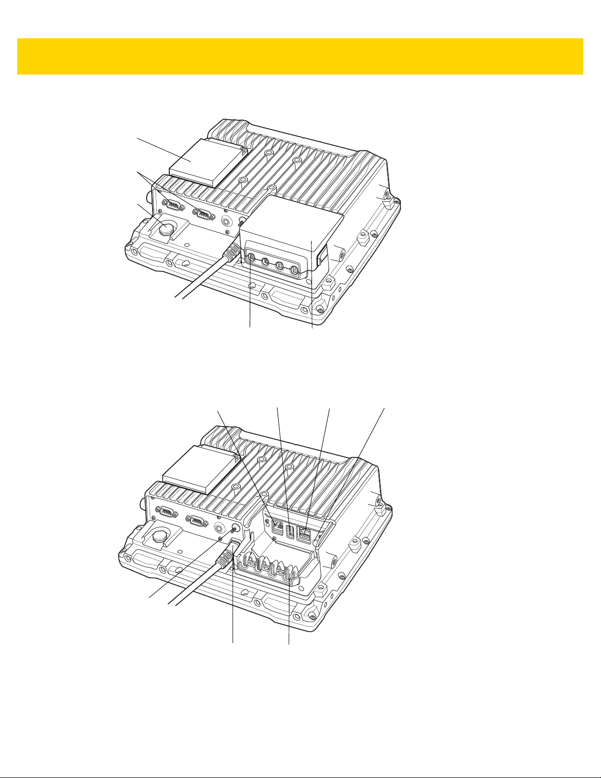
1 - 4 VC80 User Guide
Dust
Cover
RS-232
(two)
UPS
Battery
Strain Relief
(four)
Vent
Ethernet or
CAN Bus
(optional)
Standard
USB
Powered
USB
Speaker/
Mic
Strain
Relief
Power
Ground
Lug
Figure 1-3 VC80 Back View with Dust Cover
Figure 1-4 VC80 Back View without Dust Cover

Getting Started 1 - 5
Front Keys and LED Indicators
The VC80 has the following front bezel keys and LEDs:
Front Keys
Table 1-1 VC80 Front Keys
Front Function
Power Keys
On/Off Button Powers the VC80 On or Off. To reset the device, press and hold the On/Off button for
at least seven seconds until the green LED changes to amber.
Speaker/Display Speaker volume and display brightness adjustment button. Use the (-) sign to
decrease volume/brightness and use the (+) to increase the volume/brightness.
Keyboard Display on screen keyboard.
Blue Modifier Key Modifies programmable macro keys allowing for an additional six programmable keys.
Press the Blue Modifier key twice to lock the key on and to unlock, press the key once
again.
Macro Keys
Programmable
Bar Codes
Pairing Bar Code Pair peripheral Bluetooth scanners to the VC80.
Unpairing Bar Code Unpair peripheral Bluetooth scanners to the VC80.
Speaker
Front Speaker Located on front bezel.
Six programmable macro keys. When used with the Blue modifier key, six additional
programmable keys are provided. Keys may be mapped in the Control Panel by
assigning scancodes (see Chapter 6, Scancode Map) or macro mapping with
My-T-Soft.

1 - 6 VC80 User Guide
LED Indicators
Table 1-2 VC80 LED Indicators
Green/Amber
LED
Off Off Off No external power and the VC80 is not running on UPS.
Amber On Off Off External power is available but the VC80 is not turned On
Green On Off External power is available and the VC80 is turned ON.
Green Flashing
(50% Duty
Cycle On at
500ms Period)
Green Flashing
(25% Duty
Cycle On at
4000ms Period)
Green On Off Off Bezel keyboard keys: M1, M2, M3, M4, M5, M6
Green On Off On Bezel keyboard keys: M7, M8, M9, M10, M11, M12
Red LED Blue LED Description
(in shutdown or hibernate mode). The VC80 is ready to
be turned on and is currently charging the UPS battery.
The UPS battery is charging.
External power is removed. The VC80 is running on UPS
battery power.
Off Off The VC80 is in sleep mode.
Off On Off Warm up condition. The average of radio card and audio
NOTE
For fields in the above table without LED information, the LED can be On or Off dependent on user
actions and ambient temperature.
Configuring GPS
For VC80 configurations with GPS, see GPS on page 3-31 for information on setting up and configuring the GPS
with U-Center.
Flashing Red
(50% Duty
Cycle On at
500ms
Period)
Temperature related warning or error event in the
system. Average of radio card and audio codec temperature readings is either <-35° C or > +65° C. No action is
required if the OS is running. If the OS is in Sleep or
Hibernate state, then the EC should switch the VC80 Off.
codec temperature readings is between -35° C and 0° C.
The OS is not running. The Power Button is disabled.

Getting Started 1 - 7
Connecting External Devices
Disconnect the VC80 from the power supply before:
• Connecting or disconnecting external devices (e.g., scanner, keyboard).
• Connected to network.
CAUTION
Turn on external peripheral devices with power supplies at the same time or after turning on the VC80.
Ensure that the VC80 is adequately protected from power leakage caused by an external device.
Powering Up the VC80
Power up the VC80 after connecting all of the devices.
To power up the VC80, connect to an appropriate power supply and press the Power button (see Figure 1-1) or the
ignition signal.
CAUTION
Make sure there is a suitable disconnecting device such as a power switch or circuit breaker in the
power supply circuit. See Installing the VC80 on page 2-2 for more information.
Powering Down the VC80
Always shut down the VC80 as follows:
1. Select Start.
2. Select Shut Down.
1 - 8 VC80 User Guide
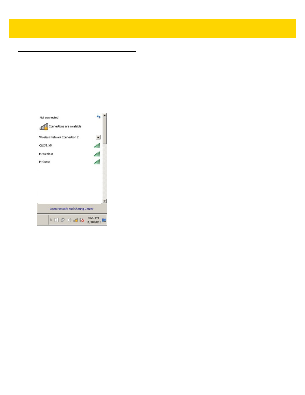
Setting Up WLAN
Connecting WLAN
To connect to the WLAN:
1. Click on the WiFi icon in the system tray to display available WLAN networks.
2. Click on the desired network and select Connect.
Figure 1-5 WLAN Connection
Getting Started 1 - 9
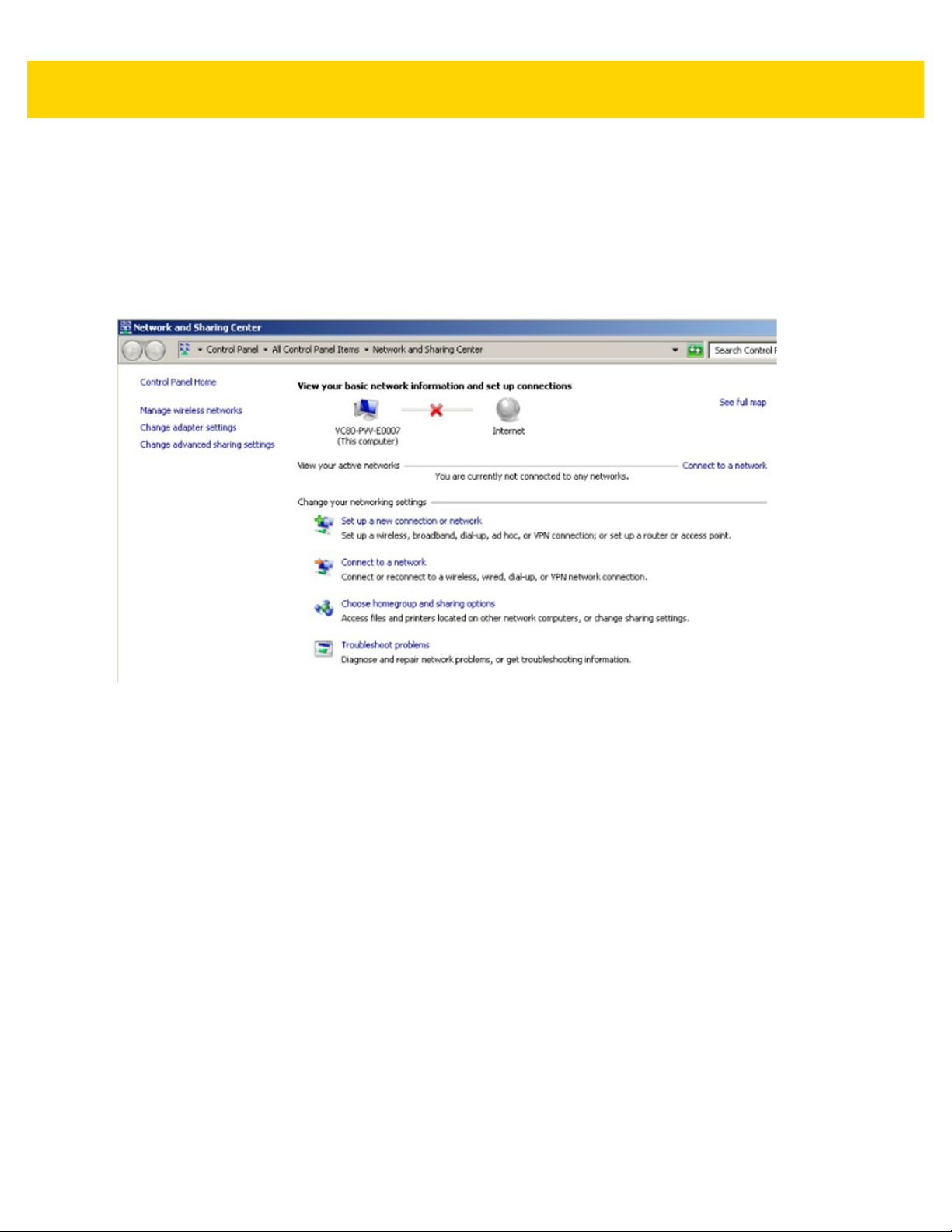
Setting Up a New Connection or Network
To set up a new connection or network:
1. Click on the WiFi icon in the system tray.
2. Select Open Network and Sharing Center (see Figure 1-5).
3. Select Set Up a New Connection or Network.
Figure 1-6 Setup New Connection or Network
4. Choose a connection option.
5. Follow the prompts to complete setup.
1 - 10 VC80 User Guide
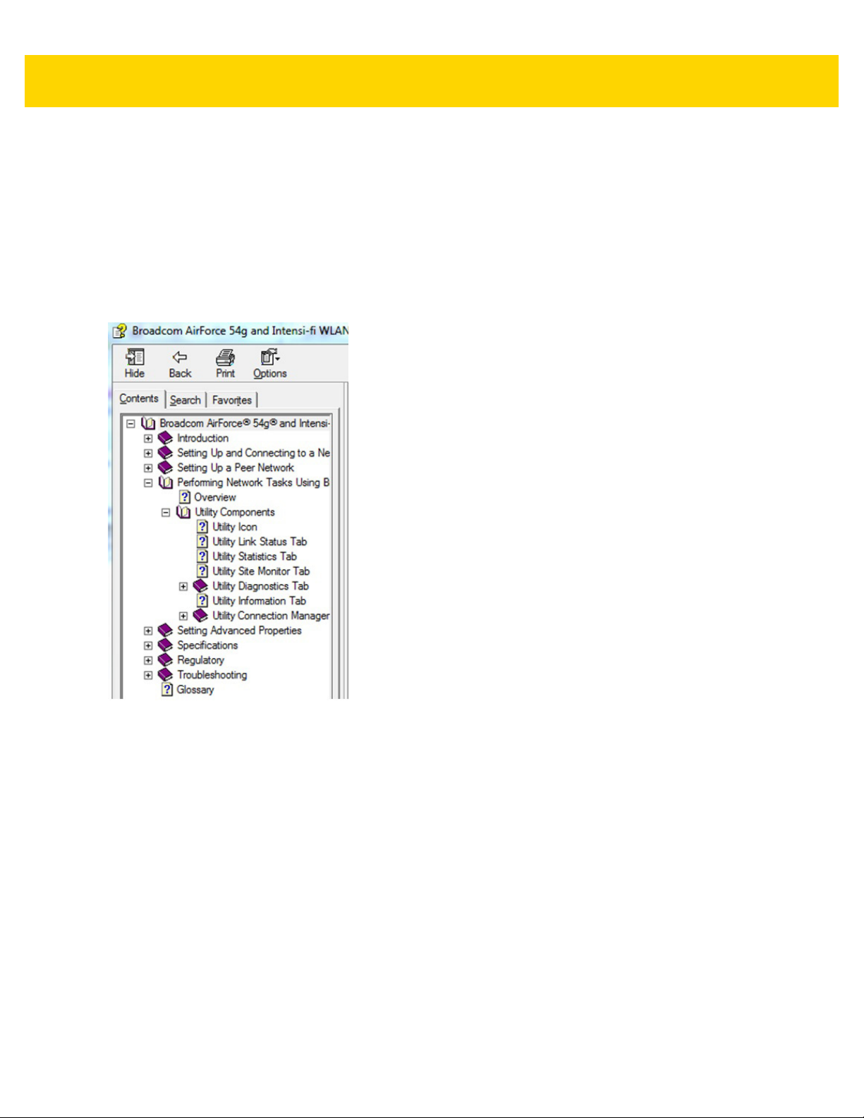
Broadcom Help
The Broadcom Help utility assists with managing the WiFi connection or network.
To access Broadcom Help:
1. Go to Start > Control Panel > Broadcom Utility.
2. Select the Help tab on the top tool bar.
3. Select the desired topics for assistance.
Figure 1-7 Broadcom Help

CHAPTER 2 INSTALLATION
Introduction
This chapter provides instructions on installing the VC80.
Overview
The VC80 can be installed in a variety of ways:
• Position the VC80 horizontally on a desk or mounted on a vehicle console.
• Wall mount the VC80 using the optional wall mount (see VC80 Mounting Accessories on page 5-7).
• Overhead mount on a lift truck cage using mounting hardware.
Depending on the vibration resistance and pivoting demands, mounting brackets, clamp foots or RAM mount
elements can also be used to attach the device. Contact your Zebra sales office to find out more about the range of
available installation options.
WARNING
!
The unit could fall during transit or installation/mounting and cause injury. Always
ensure that there are two people available when installing or removing the device.
Mounting Instructions
Follow and retain the mounting instructions included with assembly kit when installing the VC80. See Safety on
page 1-2 for safety instructions.
Heater Status
The VC80 offers a unique heater system that enables continuous operations in freezer environments. See Heater
Status on page 3-19 for information about the heater settings.
2 - 2 VC80 User Guide
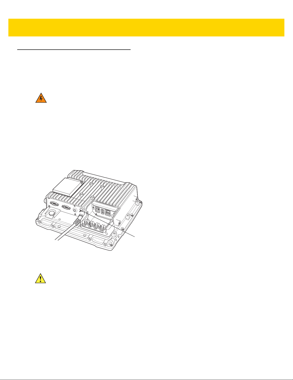
Ground Lug
Installing the VC80
Electrical Installation
There are various electrical potentials when installing the unit on a vehicle such as a forklift.
Most electrically driven forklift vehicles have floating chassis connected to
neither DC+ or DC-. However, electrical faults can cause the battery + or - to be
connected to the chassis via low resistance paths. All connected peripherals
must be completely isolated.
The VC80 accepts DC power sources with a minimum of 10VDC nominal and
48VDC nominal. A Power Pre-regulator is required for voltages above 48VDC
nominal.
Applying a voltage above 48VDC nominal without the pre-regulator or reversing
polarity may result in permanent damage to the VC80 and voids the product
warranty.
Figure 2-1 VC80 Ground Lug
CAUTION
Attach the VC80 connecting cable as close to the battery as possible. Connecting the VC80
to large electrical loads, such as converters for the forklift motor may result in random
restarts, malfunctions and/or irreparable damage to the device.
To connect devices fed by other power sources to the VC80, such as printers, power up the
peripheral devices at the same time or after the VC80 to avoid start-up problems,
malfunctions or irreparable damage to the device.

Installation 2 - 3
Wiring Guidelines
The metal chassis of the VC80 is equipped with a ground lug (located on the underside adjacent to the power
cable) to provide additional ground to the vehicle. It is strongly recommended that a grounding strap is used to
connect the ground stud on the vehicle-mount to a solid, reliable contact point on the main portion of the vehicle
chassis. It must not be connected to battery negative or terminal block.
As with other vehicle cables, carefully consider the routing of the ground strap to ensure it does not pose a hazard
to the operator or the safe operation of the vehicle. If necessary, secure the ground strap with cable ties or some
other mechanical means to prevent loops or loose lengths of wire from catching on stationary items when the
vehicle is in motion.
Before installing the cables between the mount and other devices, consider the following:
• Ensure that drilling holes do not damage the vehicle or its wiring.
• Protect cable runs from pinching, overheating and physical damage.
• Use grommets to protect cables that pass through metal.
• Use plastic straps and tie-downs to secure cables and connectors in their desired location, away from areas
where they may get snagged or pulled.
• Keep cables away from heat sources, grease, battery acid and other potential hazards.
• Keep cables away from control pedals and other moving parts that may damage the cables or interfere with the
operation of the vehicle.
IMPORTANT
Make sure the cables run inside the roll cage of the vehicle.
If the VC80 is installed in an environment where earth ground is present such as a vehicle
with metal wheels running on a metal track, or is powered by the AC/DC adaptor in a
permanent installation, the ground lug must be connected to the ground structure.

2 - 4 VC80 User Guide
Wiring Vehicle Power to the VC80
WARNING Applying voltage above the input voltage rating or reversing polarity may result
in permanent damage to the VC80 and void the product warranty.
An extension power cable is used to wire the VC80 to the truck battery (order cable separately, see Accessories on
page 5-1). Wire this cable to a filtered, fused (15A max) accessory supply on the vehicle. Follow the installation
instructions supplied with the extension cable.
Additional wiring (minimum 14 gauge), connectors or disconnects used should be rated for at least 300 VDC, 15A.
When connecting the extension power cable:
•
If a power extension cable with ignition sense is used, ensure that the ignition sense wires (18AWG wires in
red and black leads) and the power wires (14AWG in red and black leads) are reliably secured away from
each other, or are separated with reliably secured certified insulation. Minimum 2.8 mm distance, or 0.4mm
distance through insulation is required for the separation.
•
The red lead of the 14AWG power cables attach to the vehicles battery positive terminal. The 14AWG black
lead connects to the vehicle’s battery negative terminal. This should be connected to a proper terminal block
and not to the vehicle body. An optional grounding strap wire (sourced separately) may be connected to the
ground lug of the VC80 terminal connector bay and to the vehicle chassis.
•
You may have the option to connect power before or after the key switch. Though the VC80 is equipped with
a UPS, a proper shut down is recommended using the windows shut down procedure. If it is wired after the
key switch, the operator must shut down the VC80 using the Windows shut down procedure before turning
off the vehicle. If it is wired before the key switch, then to avoid excessive drain on the vehicle battery, either
the operator should shut it down when the vehicle is to be left off for an extended period, or the ignition cable
shut down wire should be connected and the VC80 configured to shut down automatically.
•
An appropriate fuse type must be used with the power extension cable according to the installation
instructions. For main power cable, use 3AB, 15A, 250V, slow blow fuse. For ignition sense input, use 3AB,
0.3A, 250V, slow blow fuse.
NOTE
The VC80 supports the ignition sense feature that detects when the ignition switch or key
switch is On or Off to allow automatic computer start up or shut down (with delay as needed).
When wiring the ignition sense wires (18AWG in red and black), the red 18AWG wire is
connected to a positive DC voltage source switched on by the ignition. The black 18AWG wire
is connected to ground reference of this switched ignition source.

Installation 2 - 5
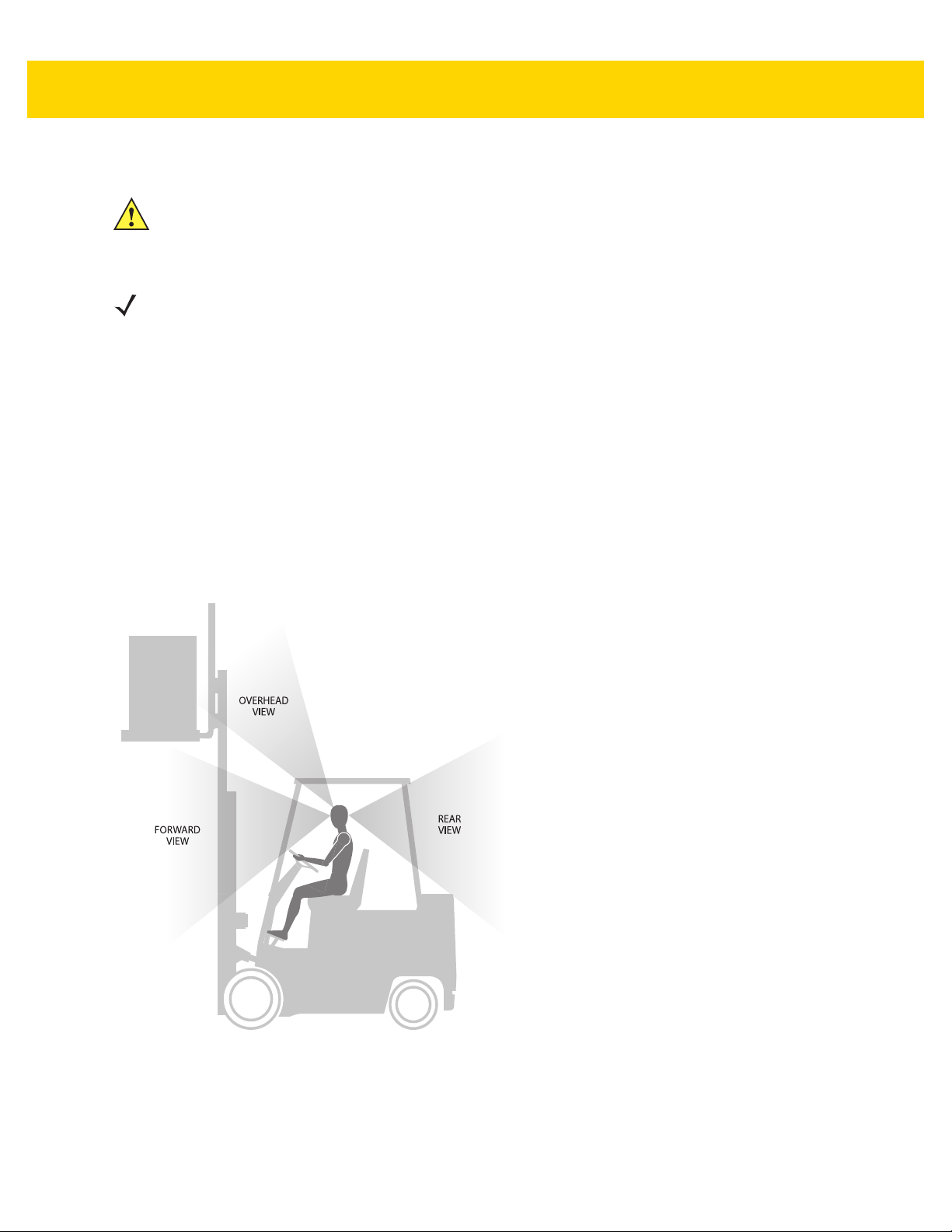
Positioning the VC80 in the Vehicle
When positioning the VC80 on the vehicle:
•
The driver's field of view must be kept free.
•
Plan for sufficient space if a keyboard and scanner are installed with the VC80.
•
No part of the VC80 system may project beyond the vehicle.
Overview of the Assembly Steps
Before fastening the VC80 to the vehicle:
•
Configure shut down automation.
•
Prepare the forklift such as ignition connection and correct voltage.
•
It is recommended to fasten the bracket to the vehicle and then install the VC80 to the bracket.
Cable Dust Cover
For the dust cover location, see VC80 Back View with Dust Cover on page 1-4.
CAUTION
CAUTION
Turn on external peripheral devices with their own power supply at the same time or after the VC80. If
this is not possible, ensure that the VC80 is adequately protected from power leakage caused by an
external device.
For safety reasons, install the supplied cable cover for the external ports prior to using the VC80.
Strain Relief
After the VC80 and bracket are fastened, prepare the strain relief as follows:
1. Install the cables loosely on the strain relief rail (see Figure 1-4 on page 1-4).
2. As far as possible, route cables leading to or away from the unit next to one another without crossing.
3. Fasten the cables into the strain relief rail precisely at the positions at which the cable openings in the cable
cover are located.
2 - 6 VC80 User Guide
View Obstruction Considerations
Installing the VC80 on a Forklift
CAUTION
NOTE
If installing peripherals, allow enough space when selecting a mounting location.
1. Attach the desired mount to the VC80. Refer to the VC80 User Guide at www.zebra.com/support for detailed
Tighten peripherals with thumbscrews by hand only. Do not use tools for tightening thumbscrews.
mounting options and instructions.
2. Attach the mounted VC80 to the vehicle and position in a location that does not obstruct the operator’s view.
3. If using an external antenna, connect antenna in a vertical position to the VC80.
4. Connect peripherals to the VC80. Place the cables in the strain relief brackets inside the dust cover and replace
the dust cover (see Figure 1-3 on page 1-4).
5. Connect the VC80 to the vehicle DC supply.
6. Press the Power button to turn the device On or Off (see Figure 1-1 on page 1-3).
Figure 2-2 View Obstruction Considerations

Installation 2 - 7
Forklift Battery Replacement Conditions
The VC80 maintains normal function of applications and connections during and after forklift battery replacement.
Replace the forklift battery at any point during a shift and/or while the VC80 is fully running.
The forklift battery may be replaced under following condition: VMC external temperature range: -30° C to +50° C.
During forklift battery replacement (VMC is running on UPS battery), both Windows and the VC80 are monitoring
remaining UPS battery capacity. The default Low Battery notification threshold is set to 20% for all Windows Power
plans. The Critical Battery threshold is set to 10%. If UPS battery is discharged below 10%, the VC80 automatically
shuts down.
An additional notification message can be enabled in the VC80 with a threshold set to the configured Low Battery
level plus an additional 10%. If enabled, this message appears to the User when the UPS battery is discharged to
30% (20% + 10%) level.
Starting from Cold Soak
The VC80 does not startup from a saturated cold soak when internal VC80 temperature (critical components and
UPS battery) is below -30° C or UPS battery has less than 10% capacity. The red LED warning indicator may
display.
The VC80 can to start up from a saturated cold soak at -30° C (or above) internal VC80 temperature when a valid
external DC power source is present.
The VC80 design minimizes wait time from -30° C cold soak to load the OS and have internal heaters to assist
system warm up.
From a -30° C cold soak condition, the VC80 battery heater may be activated to warm the UPS battery to an
acceptable charging temperature if charging is needed. The conditions and time to heat the battery are managed
by the system. The OS load time and VC80 ready for use time is independent of warming the battery.

2 - 8 VC80 User Guide
Without Power Pre-regulator
For vehicles with DC power 48V or less
With Power Pre-regulator
For vehicles with DC power greater than 48V
M1M7M2M8M3M9M4
M10M5M11M6M12
Power Extension
without Ignition Sense (p/n CA1210)
Power Extension
without Ignition Sense
(p/n CA1210)
Power Extension
with Ignition Sense
(p/n CA1220)
Power Extension
for Pre-regulator with
Ignition Sense
(p/n CA1230)
Installing the Power Pre-Regulator
IMPORTANT
The Zebra power extension cable positive lead is red and the negative lead is black.
It is recommended that all connections be secured with electrical tape or heat shrink to
prevent contaminants from degrading the connection.
To install the power pre-regulator:
1. Attach the pre-regulator cable male connector to the Zebra power extension cable which is installed on the
vehicle.
2. Connect the pre-regulator cable female connector either directly to the VC80 power cable, or to the power
extension cable. See Figure 2-3.
M1M7M2M8M3M9M4
M10M5M11M6M12
Figure 2-3 Connections To Vehicle DC Supply
Non-Vehicle Installations
Using AC power, the VC80 Vehicle-Mount Computer can be mounted at fixed locations adjacent to cross-dock
doors, manufacturing stations, or in offices.
Use the 100/240 VAC Power Supply (p/n PS000145A01) to power the computer from an AC source.
IMPORTANT
The AC/DC power supply is only intended for use at room temperature condition such as
an office environment.

Installation 2 - 9
Power On/Off with Ignition
The VC80 is equipped with an ignition sense feature which puts the terminal into suspend/shutdown when the
vehicle ignition is turned off and can power on the terminal when the ignition is switched on. To use this feature, a
power extension cable with ignition sense wires must be used and installed properly on the vehicle.
The cable in Figure 2-4 is the power extension cable (p/n CA1220) with two wires used to connect to vehicle ignition. The red and black leads of the two 18AWG wires that connect to the key switch of the ignition and ground,
respectively. Once the wires are connected, the VC80 may switch on or off depending on the state of the vehicle
ignition key. See Power on page 3-20 to select power settings.
IMPORTANT
When connecting to an ignition switch using the power extension cable with ignition sense
wires, ensure that the wires of different polarities are reliably secured away from each
other, or are separated with reliably secured certified insulation. A minimum distance of
2.8mm (or 0.4mm distance through insulation) is required for the separation.
The thinner wires (18 AWG) are used for Ignition Sense wires while the thicker wires
(14AWG) are used for Vehicle Power and Ground. Identify them carefully and
Do Not confuse them.
An appropriate fuse type must be used with the power extension cable according to the
installation instructions. For the main power cable, use 3AB, 15A, 250V, slow blow fuse.
For ignition sense input, use 3AB, 0.3A, 250V, slow blow fuse.
Figure 2-4 Power Extension Cable Kit with Optional Ignition Sense Wires (p/n CA1220)

2 - 10 VC80 User Guide
Screen Blanking Wiring
Connecting Switch for Screen Blanking
To use Screen Blanking, connect one of the two DB9 serial ports (using CA1300 Screen Blanking cable) on the
VC80 to a switch. Activate this switch electrically (e.g. motion sensor, GPS) or mechanically (e.g. pedal switch)
when the vehicle is in motion.
Figure 2-5 Connecting the Switch to the DB9 Cable
IMPORTANT
The screen blanking feature makes use of either one of the DB-9 ports to monitor electrical relay closure. When
enabled, the CTS/RTS pins of the DB9 port are continuously monitored by the screen blanking application. See
Figure 2-6 for pin configuration.
When the vehicle is in motion, the switch closes the circuit, allowing data packets to be sent or received through the
RTS and CTS pins. The computer detects that the circuit is closed and turns off the screen.
When the vehicle is not in motion, the switch opens the circuit, preventing data packets from being sent or
received. The computer detects that the circuit is open and turns on the screen.
For customers migrating to the VC80 from a 8515, 8525, 8535 vehicle mount computer or
a 753x hand-held computer cradle:
If the screen blanking feature was used previously, ensure that you are no longer feeding
the screen blanking signals to the VC80 main DC power cable. Rewire the screen
blanking inputs to the VC80 DB-9 serial port through the DB-9 screen blanking cable. In
previous generations of vehicle-mount computers, the screen blanking signals were fed in
to the terminal through 2 of the 4 wires in the CPC connector of the DC power cable. This
no longer applies for the VC80.
Figure 2-6 Screen Blanking DB9 Pin Configuration

CHAPTER 3 SOFTWARE
Introduction
This chapter provides software information and instruction for the VC80.
Microsoft Windows Setup and Configuration
After the system files are processed, Microsoft Windows loads. Standard Windows configuration options apply to
the VC80. Configuration options are located in the System Tray or the Control Panel. For example, use the System
Tray to adjust the time, date or volume level and the Control Panel to add, delete or modify software.
Folder Structure
Microsoft Windows is installed in the \Windows folder. For information on the folder structure, refer to the
commercially available Microsoft Windows OS Reference Guide.

3 - 2 VC80 User Guide
VC80 Software Components
The VC80 contains the following software components:
•
BIOS
•
Embedded Controller firmware
•
Microsoft Operating System (Windows 7 Standard or Professional).
•
VC Control Panel
The following Windows OS features are unique to the VC80 (dependent on configuration):
•
Touch driver
•
WLAN/Bluetooth driver
•
Ethernet driver
•
GPS
•
Zebra printer tools and drivers.
The Embedded Controller manages communication with the following VC80 unique features:
•
Heaters
•
Battery state
•
Data logging.
VC80 Without Operating System
The VC80 can be ordered with no operating system. This configuration requires the following:
•
Windows 7 installation media
•
A valid product licensing key.
When prompted for driver locations during installation and setup, direct the device wizard to the USB drive.
•
For Windows 7 drivers, go to: www.zebra.com/support.

Software 3 - 3
Connecting to Terminal Emulation
The VC80 supports terminal emulators such as TekTerm. For connection to a host, have the following information
available:
•
Alias name or IP host address
•
Port number of the host system
•
Emulation.
To connect to a host:
1. Ensure the mobile client network settings are correctly configured.
2. Ensure the VC80 is connected to the network if connecting via WLAN.
3. Launch the terminal emulation application.
TekTerm
TekTerm is a powerful terminal emulation software application with the ability to interface with multiple Bluetooth
and serial scanners. TekTerm is pre-licensed and pre-installed on the VC80.
It is recommended to check the latest TekTerm version released for the VC80. For more information regarding
TekTerm, go to: www.zebra.com/support.

3 - 4 VC80 User Guide
Bar Code Scanners and Settings
The VC80 supports the following types of bar code scanners:
•
Tethered scanner connected to COM1 or COM2.
•
Tethered scanner connected to a USB host port
•
Wireless scanner connected via Bluetooth.
Serial Scanners
To configure serial scanners:
1. Open the VC Control Panel and select Power.
2. Enable the power to the port.
Figure 3-1 Enable Power for Serial Scanners

Software 3 - 5
3. Select TekWedge and select Enable TekWedge to support serial scanners.
4. Select Config Ports.
Figure 3-2 Enable TekWedge for Serial Scanners
5. Select the new COM port and select Enable Port.
Figure 3-3 Enable Port for Serial Scanner
6. Select OK.

3 - 6 VC80 User Guide
USB Scanners
The Windows OS loads a USB driver for USB scanners. USB scanners are not controlled or managed by
TekWedge therefore, post processing such as translation rules can not be used with USB scanners. 123Scan
be used to create rules and download to the scanner.
To configure USB scanners, connect the scanner to the VC80 USB port and follow the scanner setup instructions.
For Zebra scanner guides, go to: www.zebra.com/support.
Bluetooth Scanners
See Quick Setup on page 3-10 for information on connecting Bluetooth scanners. Always use TekWedge on page
3-24 to configure Bluetooth parameters.
Pairing Bluetooth Scanners Using Bar Codes
NOTE
If the Bluetooth scanner connection to the VC80 is lost, it is recommended to first scan the Unpair bar code
and then scan the Pair bar code.
To pair Bluetooth scanners using bar codes:
1. Select Bluetooth >Open Settings to access Bluetooth settings.
2
can
Figure 3-4 Open Settings

Software 3 - 7
2. In the Options tab, select check boxes under Discovery and Connections.
Figure 3-5 Bluetooth Discovery and Connections
3. In the COM Ports tab, select Add.
4. Select the radio button Incoming (device initiates the connection).
5. Select OK.
Figure 3-6 Add Incoming Bluetooth Devices

3 - 8 VC80 User Guide
6. Open the VC Control Panel and select TekWedge.
7. Enable TekWedge.
8. Select Config Ports.
Figure 3-7 Enable TekWedge
9. Select the new COM port and select Enable Port.
Figure 3-8 Enable COM Port for Bluetooth Device
10. Select OK.
11. Scan the bar code to pair the scanner (the scanner must be configured for SPP mode).

Software 3 - 9
Settings
Select Start Menu > Admin Tools > VC Control Panel to configure the following VC80 settings:
•
Quick Setup
•
Bezel Keypad
•
Haptics Feedback
•
Heater Status
•
Power
•
Push to Talk
•
Screen Blanking
•
System Info
•
TekWedge
•
UPS Battery
•
Data Logging
Figure 3-9 VC80 Settings

3 - 10 VC80 User Guide
Quick Setup
Select Start Menu > VC Control Panel > Quick Setup to configure the following quick setup options.
Links to Microsoft or third party utilities:
•
Touch Panel Calibration - Calibrate the touch panel.
•
WLAN Configuration - Configure WLAN.
•
Network Configuration - Configure network parameters such as, Static IP address and DHCP.
•
On-Screen Keyboard Configuration - My-T-Soft Keyboard configuration.
VC80 control panel:
•
Manage VC Configuration - Load or save configuration files.
Figure 3-10 Quick Setup Settings

Software 3 - 11
Touch Panel Calibration
Hardware
Associates the pointer device with the monitor/desktop area that is controlled by the device and shows the
hardware port information.
NOTE
Select Help for detailed information on the Touch Panel Calibration options.
• Handling Whole Desktop - Whole indicates the primary monitor.
• Connected to USB Port - Displays the port connected to the device.
• Add a New Device - Option to add a device. Only non USB devices are manually added. USB devices
are automatically added.
• Remove this Device - Option to remove a device. Only non USB or inactive USB are manually
removed.
Figure 3-11 Hardware Settings

3 - 12 VC80 User Guide
Click Mode
• Interactive Touch - Shows the current click mode emulation for a single touch. The setting is only
active if the driver is responsible for the pointer handling via the standard mouse interface into the OS.
• Extended Touch - Vista and above, UPDD can deliver touch co-ordinate data to the Windows OS via
three interfaces: mouse class, HID class, Win8TI API interface.
• Visual Notification - Indicates if visual feedback is shown during Interactive Touch right click
countdown.
• Interactive Switch Delay - Select the delay pace.
• Sound Options - Configure touch sound options.
• System Mouse Settings - Adjust the mouse pointer settings defined within the OS.
• Test Icons - Test Right Click and Double Click. A tick is shown if the click test is successful.
Figure 3-12 Click Mode Settings

Software 3 - 13
Properties
• Name - Associates a name to the device. By default the name is the drivers controller device name.
• Low Pass Filter - Applies a filter to produce a smoother drawing. The speed of drawing is affected, the
higher the value used.
• Liftoff Time - Specifies the time interval required to register a stylus lift after the last touch packet is
received. Lift off time is defined in units of 10ms.
• Stabilization - Causes small movements to be ignored.
• Averaging - Applies a filter to produce smoother drawings. Filtering can improve drawing without
affecting the drawing speed.
• Mode - In a multi pointer device environment, this setting indicates the priority given to the device. With
the Interlock option, the device can only be used if no other device is in use. The Admin option allows
any device currently in used to be forced into a pen up state and the device is given immediate priority.
• Release Time - Defines the interlock release times.
• Use Lift-off Packet - Only shown if a pen up data packet is generated by the device on stylus lift off.
• Anchor Mouse - If the device generates a pen up data packet on stylus lift, the mouse cursor returns
to its original position after using the pointer device.
• Enabled - Indicates if the device is enabled. This is an option to free up resources without uninstalling
the driver.
• Advanced - Includes advanced features such as, Edge Acceleration, Ignore Touches Outside
Calibrated Area, Support for New Events, and Portrait Rotation.
Figure 3-13 Properties Settings

3 - 14 VC80 User Guide
Calibration
• Style - Invoke Calibration styles manually, from an application, a toolbar, or a command line interface.
• Add a New Style - Add a new calibration style.
• Number of Points - The number of calibration points determines the calibration pattern used. It is
highly recommended that four or more points are used for greater flexibility.
• Margin % - The percentage margin from the edge of the visual display area from which to draw the
calibration points.
• Timeout (secs) - Specifies the number of seconds to wait for a calibration touch before canceling the
calibration procedure.
• Use Eeprom Storage - Store calibration data in the controllers Eeprom.
• Confirm After Calibration - Select to use new calibration data.
• Sound Options - Calibration sound options.
• Calibrate - Invoke calibration procedure for the current device. When calibrating for the first time in a
multi-monitor environment, calibrating the devices also sets up desktop/touch device relationships.
Figure 3-14 Calibration Settings

Software 3 - 15
Status
• Controller Type - The actual controller type in use irrespective of the name given to it in the UPDD
console.
• State - Indicates if the device is enabled at the UPDD level.
• Macro Result - Shows if a controller is initialized by the driver.
• Replay Initialization Macro - Reinitializes the controller. The macro, if defined, is sent to the controller.
• Reset Error Counts - Reset the sync error count. Only enabled if error count > 0.
• Reload Driver Settings - Reload the driver.
• Show Test Screen - Invoke the test utility.
• Show Test Grid - Invoke the test utility with drawing grid.
• Dump Settings - Dump driver settings to a file. The file is useful for support purposes but can also be
used in subsequent installs to define the initial settings.
Figure 3-15 Status Settings

3 - 16 VC80 User Guide
Manage VC Configuration
• Import - Load VC configuration from file.
•Export - Export VC configuration to file.
• Restore Default - Sets all parameters to factory default.
Figure 3-16 Manage VC Configuration

Software 3 - 17
Bezel Keyboard
•
My-T-Soft Macro Mapping - Allows remapping and/or assigning various custom functions to the Bezel
buttons.
•
Assign Bezel Key Scancodes - Map bezel keys one of the following ways:
• Bezel Key - Assign bezel key using the drop-down menu.
• Assign Scancodes - Assign scancode function from drop-down menu. To change scancodes to assign
unique functions/characters, see Chapter 6, Scancode Map.
•
Blue Key
• One-Shot -Activates the Blue key function on the first key press and remains activated until any key is
pressed again.
•Lock - Activates the Blue key function on the first key press and remains activated until the Blue key is
pressed again.
• One-Shot/Lock - Activates the Blue key function on the first key press. The second Blue key press locks
the Blue key function. The third Blue key press deactivates the function.
Figure 3-17 Bezel Keyboard Settings

3 - 18 VC80 User Guide
Haptic Feedback
•
Haptics Feedback
• Enable/disable Haptics Feedback.
• Select Full Screen or My-T-Soft Only.
•
Parameters
• Select the haptics waveform type: Long Double Sharp Click Waveform or Strong Click Waveform.
• Select the haptics waveform level.
Figure 3-18 Haptics Feedback Settings

Software 3 - 19
Heater Status
The VC80 heater ensures optimum performance in freezers. The heater benefits include:
• Touch screen heater clears condensation on the display.
• Port heater prevents condensation on contacts.
• Audio Codec, UPS Battery and WLAN/BT radio require heaters to operate below freezing temperatures.
• The user interface displays current temperatures.
Heater Status settings:
•
Current Temperature - Displays internal and external temperatures.
•
Display Temperature - Select desired temperature scale.
•
Temperature Status
• Green LED - Heater is enabled.
• Red LED - Heater is disabled.
• Start Test - Verifies heater operation when temperature increases.
Figure 3-19 Heater Status Settings

3 - 20 VC80 User Guide
Power
NOTE
Ignition detect requires a CA1220 power extension cable.
•
Interface Power Configuration - Enable/disable power for serial and USB ports.
NOTE
To configure a serial scanner, turn on the power to the port and in TekWedge settings, enable
the port and TekWedge (see
•
Vehicle Ignition Detection
• Start VC when vehicle ignition changes from OFF to ON state.
• Shut down VC when vehicle ignition changes from ON to OFF state.
• Enter desired minutes to delay in the Delay field.
TekWedge on page 3-24
).
Figure 3-20 Power Settings

Software 3 - 21
Push To Talk
•
Connection Status - Displays the current connection status.
•
PTT Handset Scan Code - Scan code for bezel key setting.
•
Speaker - Enable the Bezel Speaker or PTT Handset Speaker.
Figure 3-21 Push To Talk Settings

3 - 22 VC80 User Guide
Screen Blanking
The optional Screen Blanking setting turns the screen off when the vehicle is moving and back on when the vehicle
is stopped.
NOTE
To use Screen Blanking, first connect one of the two DB9 serial ports on the VC80 to a user-supplied
switch or relay. See Connecting Switch for Screen Blanking on page 2-10.
•
Screen Blanking - Enable/disable screen blanking feature.
•
Delay
• Blanking the VC Screen - Screen blanking duration in seconds.
• Re-Enabling the VC Screen - Re-enable screen duration in seconds.
•
Blank Screen Based On
• Com Port 1 or Com Port 2.
• Blank screen when port pins are connected - Select blank screen option. De-select to disconnect the
blank screen option.
Figure 3-22 Screen Blanking Screen

Software 3 - 23
System Info
The System Info screen provides information about the system such as the Serial Number, OS Details, and SKU
Detail. The system information is required for technical support inquiries.
To export the system information to a text file:
1. Select Save.
2. Select a location to save the file to.
3. Name the file in the File Name field.
4. Select a file type from the Save As Type drop-down menu.
Figure 3-23 System Information

3 - 24 VC80 User Guide
TekWedge
TekWedge provides the ability to interface with Serial and Bluetooth scanners.
NOTE
To configure a serial scanner, turn on the power to the port (see
TekWedge settings, enable the port and TekWedge.
•
TekWedge to support serial scanners - Enable/disable TekWedge support for serial and Bluetooth
scanners.
•
Properties
• Enable Good Scan Beep - VC80 beeps when data is received from the scanner.
• Code Page - Select code page from drop-down menu.
•
Data Transmission - Select one type of data transmission.
• Copy/Paste (Application supports Ctrl-V) - Copy/Paste is efficient for large amounts of scanned data.
• Keyboard Wedge.
•
Ports and Translation Rules
Power on page 3-20
) and in
Figure 3-24 TekWedge Settings

Software 3 - 25
• Config Ports - Select the COM Port from the ports window and adjust the port settings such as Baud
Rate, Data Bits, Parity, Flow Control, Stop Bits, and Timeout as desired.
• Set to Default - Sets the default for the selected COM port.
• Clear Unavailable Ports - Clears unavailable ports such as ports that are no longer active.
Figure 3-25 Config Ports
NOTE
For large bar codes, adjust the Timeout duration. The longer the timeout, the slower the scans.

3 - 26 VC80 User Guide
• Config Translation Rules - Allows you to define up to 10 cases, each consisting of up to 10 rules in
sequential order. Only one case is applied to a bar code and a case is applied if all rules specified in the
case are successful. If a rule within a case fails, the entire case fails.
• Case Rules -The case rules are defined as follows:
•No Rule
• Verify Barcode Size — Verifies the barcode size. Assign this rule first, before creating subsequent
rules.
• Match at Index — Matches the match string at a specified index.
• Add Barcode Prefix/Suffix — Adds a global prefix or suffix.
• Search and Replace — Replaces all instances of the match string.
• Match and Replace at Index — Matches the match string at a specified index and replaces/changes
it.
• Replace at Index — Replaces/changes unspecified data in a given range.
Translation information about the status of each case/rule is displayed in the scan log file. This is useful to
determine why a rule is failing.
Select a Case/Rule to modify and then select the Scan Type drop-down menu to apply a rule.
Figure 3-26 Translation Rules

Software 3 - 27
UPS Battery Status
•
Information - Displays the current battery information such as the Serial Number, Manufacture Date, and
Remaining Battery Life.
•
Notification - Enable/disable Low Battery Notifications and enter a Threshold percentage for low battery
life warnings.
Figure 3-27 UPS Battery Settings

3 - 28 VC80 User Guide
Data Logging
Data Logging logs information about VC80 custom features.
•
Log Information Level
•Source - Select a source from the drop-down menu such as Heaters, Haptics, UPS Battery.
• Content - Select a priority level from the drop-down menu such a Critical, Major, Minor.
• Disable All Logging - Removes logging VC80 custom feature information.
•
Log File Management - Select a Log File Location, quantity of log files in the Create up to field, and disk
size (default is 2 MB) in the Total Size On Disk field.
Figure 3-28 Data Logging Settings
NOTE
Application crash dump files are captured and stored in a restricted folder permitted for
Administrators only (C:\VC\Logs or C:\Windows\MiniDmp).

Software 3 - 29
My-T-Soft
My-T-Soft offers a database of existing keyboard layouts for screen keyboard customization and key mapping.
Each VC80 has access to a Zebra account on the Build a Board website for keyboard layouts. Unique custom
keyboard layouts may be acquired for additional license fee(s).
To access My-T-Soft, go to: www.build-a-board.com.
Figure 3-29 My-T-Soft Screen Keyboard Layout Examples

3 - 30 VC80 User Guide
All VC80s are My-T-Soft licensed through a common account which is only available from the VC80.
To access My-T-Soft:
1. Select Start > Select My-T-Soft > Licensing Information.
Figure 3-30 My-T-Soft License Information
2. The UAC window displays. Select Yes.
3. In the IMG License Manager menu, select Go to My Build-A-Board.com Account.
Figure 3-31 IMG License Manager
4. The Zebra account web page displays. Download existing keyboards or create your own and save in the Zebra
account.
NOTE
To create a private collection of keyboards, you must acquire your own account.

Software 3 - 31
COM Port Connection
Windows Management Instrumentation
Windows Management Instrumentation (WMI) is a free component of the Microsoft Windows® operating system
that provides a scalable system management infrastructure. Using a free provider plug-in from Zebra, WMI
enables local and network remote management of scanner(s). System administrators can leverage WMI to query
and set information on desktop systems, applications, networks, components, and accessories, such as a scanner.
For more WMI information, go to:
•
https://msdn.microsoft.com/en-us/library/aa384642(v=vs.85).aspx
•
http://www.zebra.com/support
GPS
U-Center is used to set up GPS on the VC80.
To set up the GPS:
1. Ensure that the antenna is properly installed on the GPS port (see Figure 1-2 on page 1-3).
2. Open U-Center by selecting Start > Program Files > U-Center.
3. Ensure that the receiver is connected. See Figure 1-2 on page 1-3. After approximately thirty seconds, some of
signals bars turn to green. This signifies that the GPS has obtained 3D lock.
Figure 3-32 U-Center Connection

3 - 32 VC80 User Guide
Satellite Level
To view the Satellite Level, select View > Docking Windows > Satellite Level.
Location Coordinates
To view Location Coordinates, select View > Docking Windows > Data.
Figure 3-33 Location Coordinates
U-Center Software
•
For detailed U-Center information, refer to the U-Center User Guide at:
https://www.u-blox.com/sites/default/files/u-center_UserGuide_%28UBX-13005250%29.pdf
•
Other applications/software such as Visual GPS can be used to collect location data by communicating with
the GPS receiver.

CHAPTER 4 MAINTENANCE AND
TROUBLESHOOTING
Introduction
This chapter includes instructions on cleaning the device and provides troubleshooting solutions for potential
problems during device operations.
WARNING Danger due to electric shock when cleaning and maintaining the device. To avoid
electric shock, turn the VC80 off and disconnect it from the power supply before
cleaning or maintaining it.
Cleaning
CAUTION
Do not use compressed air, a high-pressure cleaner or vacuum cleaner, as this can damage
the surface. Using a high-pressure cleaner poses the additional risk of water entering the
device and damaging the electronics or display.
Housing Cleaning
Clean the fully assembled VC80 vehicle mount computer housing using only a mild detergent on a lightly dampened soft cloth.
Touchscreen Cleaning
•
Use neutral detergent or isopropyl alcohol on a clean soft cloth to clean the panel surface. Do not use any
kind of chemical solvent, acidic or alkali solution.

4 - 2 VC80 User Guide
Touchscreen
The VC80 is equipped with a resistive touchscreen.
CAUTION
Operation of the resistive touchscreen is recommended with:
• Clean, dry fingers.
• Clean, dry, soft gloves.
• Suitable touch stylus (plastic or wood, rounded tip).
- Keep the touchscreen clean (see Touchscreen Cleaning on page 4-1).
- Do not apply adhesives to the surface.
- Avoid high voltage and/or static charge.
- Do not use ball point pens, writing utensils, tools, or sharp objects.
- Touch the panel with your finger or stylus only to ensure normal operation.
- Operate in a stable environment. Abrupt variation of temperature and humidity may cause malfunction.
- Avoid applying excessive activation force or sudden impact on the touchscreen surface.

Maintenance and Troubleshooting 4 - 3
Troubleshooting
Table 4-1 Troubleshooting
Symptom Possible Cause Solution
The vehicle
computer does
not power on or
shuts off
suddenly.
Cannot see
characters on
display.
The power cable ignition
sense wire (yellow) is not
connected properly.
Power cable not
connected properly or
unplugged.
If the vehicle computer is
powered by a vehicle
battery, the vehicle
battery is depleted.
Vehicle computer not
powered on (Power LED
is Off).
Screen is too bright/dark. Adjust the brightness; see
Display not adjusted
properly.
The vehicle computer is
in low power mode
(Power LED is on).
Verify that the power cable is connected properly. See
Vehicle Power to the VC80 on page 2-4
Connect power cable to power cable portion underside of
vehicle computer. Turn the main power switch on.
Replace or charge the vehicle battery.
Press the Power button on.
Select
Display
display.
Press the Power button to turn on the vehicle computer.
in the Control Panel settings and adjust the
.
Figure 1-1 on page 1-3
Wiring
.
The touchscreen
is not working.
Display not properly
calibrated.
Replacement screen
protector was not applied
correctly.
Recalibrate the screen through the Touch Panel Calibration
utility (see
continues, contact Zebra support. See
page ii-x
Replace or re-apply screen protector.
Touch Panel Calibration on page 3-11
.
Service Information on
). If problem

4 - 4 VC80 User Guide
Table 4-1 Troubleshooting
Symptom Possible Cause Solution
The optional
serial scanner
does not
operate.
No sound is
heard when you
tap the
touchscreen or
press a key.
Scanner is not properly
connected to the vehicle
computer.
TekWedge application is
not enabled or set to the
correct COM Port.
External power is not
connected.
Volume is turned down. Adjust the volume in the Control Panel.
Application currently
running disabled the
sound.
Faulty speaker. Contact Zebra support at www.zebra.com/support.
The optional external
speaker cable is
connected without the
speaker.
Connect the scanner to the COM1 port. Ensure the proper COM
port is selected in the TekWedge application, see
page 3-24
Product Reference Guide.
Ensure that the TekWedge application is enabled and set to the
correct port. See
Verify external power connection.
Configure the application to enable the sound.
Connect the external speaker or disconnect the cable.
. If the problem continues, refer to the scanner
TekWedge on page 3-24
.
TekWedge on
Missing pixels on
the display.
COM1 or COM2
port is not
working.
No keys are
working on the
optional or
built-in keyboard.
Power is not enabled on
the COM port.
Faulty LCD. Contact Zebra support. See www.zebra.com/support.
Another application, or
SerialWedge is using the
port.
The optional keyboard is
not properly connected to
the vehicle computer.
The application does not
require keyboard input.
Vehicle computer is not
responding.
Ensure the power is applied to the COM port by the VC80.
Stop the application using the port or change the TekWedge
COM Port Settings.
Check the cable connections between the keyboard and the
vehicle computer.
Configure the application to use the keyboard.
Warm boot the vehicle computer.

Maintenance and Troubleshooting 4 - 5
Table 4-1 Troubleshooting
Symptom Possible Cause Solution
The vehicle
computer
cannot find any
Bluetooth
devices nearby.
When installed
on some electric
forklifts, the
scanner range is
shorter then it is
when installed
on other forklifts.
Too far from other
Bluetooth devices.
The Bluetooth device(s)
nearby are not turned
on.
The Bluetooth device(s)
are not in discoverable
mode.
Electro-magnetic
interference caused by
the forklift.
Move closer to the other Bluetooth device(s).
Turn on the Bluetooth device(s).
Set the Bluetooth device(s) to discoverable mode. If needed,
refer to the device’s user documentation for help.
Consult forklift vendor about reducing the interference by
adding a capacitor between the forklift chassis and its
battery's negative terminal, or another recommended solution.

4 - 6 VC80 User Guide

CHAPTER 5 ACCESSORIES AND
MOUNTING
Introduction
This chapter provides accessory information, mounting options and instructions.
Accessories
Table 5-1 Accessories
Model Number Accessory
Antennas
AN2010 Antenna, dual band, 802.11 a/b/g/n, 2 dBi, reverse polarity SMA connector, magnetic
mount, 2.9m
AN2020 Antenna, 2.4GHz, 802.11 b/g, 5 dBi, reverse polarity SMA connector, magnetic
mount, 2.9m
AN2030 Whip antenna (stubby), dual band, 802.11 a/b/g/n, 2.4GHz 2dBi, 5GHz 3.7 dBi,
reverse polarity SMA connector
20667-002 Whip antenna (stubby), 802.11 b/g - dipole 2 dBi reverse polarity SMA connector
AR1000 Right Angle SMA reverse polarity plug-jack adaptor
AN000090A01 GNSS antenna, magnetic mount, 2.9 m cable

5 - 2 VC80 User Guide
Table 5-1 Accessories
Model Number Accessory
Mounts
MT4200 Quick release mount
MT4205 Mounting plate for the MT4200 quick release mount
MT4210 Adaptor bracket kit for 82XX quick release mount
MT4510 RAM rectangular base with 2.25" rubber ball
MT4301 RAM mount, 4" arm
MT4302 RAM mount, 12" arm
MT3501 VESA base (for 4" or 12" RAM arm)
MT3502 Circular base (for 4" or 12" RAM arm)
MT3505 Clamp base (for 4" or 12" RAM arm), 2" max. width
MT3507 Clamp base (for 4" or 12" RAM arm), 3" max. width
MT3509 Rail base (for 4" or 12" RAM arm), 1-1/4" to 1-7/8"
MT3510 Rail base (for 4" or 12" RAM arm), 2" to 2 1/2"
KT-SCANMNT-VC80-R Side mounted holder for scanner
KT-KYBDTRAY-VC80-R Keyboard mounting tray (includes tilting arms, knobs and screws) for VC80 and iKey
keyboards
KT-KYBDMNT-VC80-R Function/Numeric keypad side mount bracket

Accessories and Mounting 5 - 3
Table 5-1 Accessories
Model Number Accessory
Keyboard
9010376
9010377 iKey keyboard, 72 oversized color arranged keys (8 function keys), USB
SLK-101-M-USB-3F iKey keyboard, 101 keys (12 function keys), large numeric pad, backlight, USB
Speaker/Mic
M1000 Speaker/Mic with push-to-talk function
Miscellaneous
KT-SPRTCT-VC70-05R Screen protector pack of 5
SL0001 Stylus and stylus holder
KT-VC80-BTRY1-01 Spare battery
iKey keyboard, 86 keys (12 Function keys), pointing device, red LED backlight, USB

5 - 4 VC80 User Guide
Table 5-1 Accessories
Model Number Accessory
Power Supplies and Cables
PS000145A01 100/240 VAC power supply, 24 VDC, 6.5 A, 150W (AC power cord sold separately)
PS1370 Pre-Regulator, 19 - 90 VDC in, 15 VDC out, 90 W
CB000417A01 DC power adaptor to VC50
CB000416A01 DC Power adaptor to VC70
CA1210 Power extension cable, DC, 6', waterproof
CA1230 Power extension cable for pre-regulator
CA1220 Power extension cable, DC, 180 cm, with ignition sense
CA1300 Screen blanking cable (DB9 to open wires)
CB-000433-01 CAN Bus cable (RJ45 to Deutsch)

Accessories and Mounting 5 - 5
External Bar Code Scanners
CAUTION
The VC80 supports external hand-held decoded scanners and imagers connected via USB, RS-232, or Bluetooth.
See Bar Code Scanners and Settings on page 3-4 to add scanner(s).
When a bar code is scanned successfully, the VC80 beeps if configured appropriately. A poorly printed or damaged
bar code may not decode properly. In this case, use the keyboard to enter data from the bar code.
For more information, refer to the specific scanner manual at: www.zebra.com/support.
Only use Zebra approved scanners.

5 - 6 VC80 User Guide
AR1000
AR3010
AN2020
AN2030
AN2010
Contact
Insulator
SMA
Connector
Black Powder Coat
Over Nickel Chrome
Plated Steel
COAX LMR
200
Red Cap Vinyl
80 lbs Pull
Strength
Magnet
NHOMF
Magnetic Mount for
AN2010 and AN2020
VC80 Antenna Options
Antenna hardware configurations are located in Table 5-1 on page 5-1. To determine the best antenna option for
your location, contact your Zebra representative.
IMPORTANT
If using a magnetic mount antenna, place it in a location that balances the need for the VC80 to
communicate with the access points and local Bluetooth peripherals
.
Figure 5-1 VC80 Antenna Options

Accessories and Mounting 5 - 7
VC80 Mounting Accessories
WARNING Failure to install the mount correctly, or modifications to the mount, may result in serious
injury or damage to property. Contact Zebra Technical Support or your Zebra representative if you have problems installing this mount. To ensure operator safety, you must use a
calibrated torque wrench and the supplied mounting hardware when fastening the computer and mount. Use of this mount in vehicles driven on public roads or highways is
prohibited. Contact Zebra for further details.
Before mounting a VC80 in a vehicle, there are a number of operator safety issues that
require careful attention. When mounting a VC80 use only approved Zebra mounting
hardware and mounting parts which are specific to the VC80 model purchased. An
improperly mounted VC80 or use of non-approved parts may result in one or more of the
following: operator injury, property damage, operator visibility obstruction, operator distraction, and/or poor ease of egress for the operator. Zebra strongly recommends that you
seek professional mounting advice from the vehicle manufacturer.
If it is necessary to mount the VC80 overhead, or in any position that could cause injury to
the operator should the unit fall, it is critical that a secondary tether or other fail safe
device be installed.
The following restrictions must be strictly enforced:
•
Do not use the mount and/or the VC80 as a hand-held. Using the mount in this manner
may cause the person to fall or dislodge the mounting hardware and/or mounts.
•
Do not add weight or attach any other items to the mount or VC80. Additional elements
may fall causing injury, or may increase the chance of failure and/or damage in
mounting hardware and/or mounts.
•
Mounts used in industrial or vibration generating environments may be subjected to
fatigue, stress, and/or part wear. A periodic inspection of the mounting hardware and
mounts should be performed to ensure parts are retightened to the correct torque, free
of fractures, excessive wear, and/or other environmental damage. Any parts found to
be unsafe should be removed and replaced immediately. After inspection or
replacement of parts, readjust the mount as outlined in the pertinent sections below.
•
Cable routing within a vehicle cab also requires careful consideration, especially for
separately connected scanners and other devices with loose cables. If you are unable
to obtain suitable advice, contact Zebra for assistance. For better protection, the
equipment should be mounted inside the vehicle roll cage.
•
When charging the vehicle battery, the VC80 must be either disconnected from the
battery or it must be determined that the maximum allowed input voltage of the VC80 is
not exceeded.

5 - 8 VC80 User Guide
MT43XX RAM Mount
IMPORTANT
IMPORTANT
The VC80 may be installed using an articulating RAM Mount (Model MT43XX – 4 in. or 12 in. arm) secured to
either a VESA or circular base.
The RAM articulating mount can be installed in a variety of orientations (see Figure 5-3 on page 5-9). Select the
best orientation for the specific application. Preferred orientations maintain the center of mass of the computer
assembly, directly over the center of the base.
For detailed mount installation information, refer to the instructions included with the mount kit.
To avoid injury, this device must be properly secured when in a moving vehicle.
Keep this device away from magnetic fields.
Do not place the computer near a television or radio receiver.
Do not disassemble the VC80 computer as there are no user-serviceable parts inside.
The operator can easily adjust the tilt and rotation of the VC80. Use care to avoid operator
injury or equipment damage if the computer slips due to a loosened hand screw.
Figure 5-2 Orientation of Vehicle-Mount Assembly

Accessories and Mounting 5 - 9
LOWE R
BASE
NUT
CLAMP
BASE
SCREW
LOWE R
BASE
NUT
CLAMP
BASE
SCREW
LOWE R
BASE
SCREW
CLAMP
BASE
NUTNUT
CLAMP
BASE
SCREW
LOWE R
BASE
MT3505 MT3507
MT3510MT3509
Optional Mounts
One of the following optional mounting kits shown in Figure 5-3 may be substituted for the Vesa base or the circular
base when mounting to a post or forklift roll cage.
To assemble the optional mount kit:
1. Mount the clamp base and lower base around the shaft.
2. Place the screw through the clamp and the lower base, and affix with the nut.
3. Torque to 26 in-lbs.
4. Secure the RAM standard arm by inserting the RAM balls into both ends of the arm sockets.
Figure 5-3 Optional Mount Kits
Plate Bases for MT35XX Mounts
Plate bases are not recommended for forklift mounting solutions. If this requires a plate rather than a clamp base,
you must penetrate into the structure of the vehicle. This requires additional hardware. The following plate bases
are available:
•
MT3501 - VESA Plate
•
MT3502 - Circular Plate

5 - 10 VC80 User Guide
Spring
Clip
MT4200
Back Mounting
Plate Hooks
MT4205 Base
Plate Slots
MT4200 Quick Release Mount
The MT4200 Quick Release Mount allows a removal without the need for tools.
Assembling MT4200
To assemble the MT4200 Quick Release mount:
1. Place the back mounting plate hooks into the base plate slots.
2. Snap spring clips into place.
Figure 5-4 MT4200 Quick Release Mount Assembly

Accessories and Mounting 5 - 11
Hex Head
Screw
Washer
Spring
Lock
Washer
Flat
MT4200
Mounting
Bracket
Detailed View
MT4200
Mounting Bracket
(Back View)
Attaching MT4200 to VC80
To attach the MT4200 Quick Release Mount to the VC80:
1. Line up the MT4200 mounting bracket holes with the holes on the sides of the VC80 (two on each side).
2. Place the washer spring lock onto the hex head screw.
3. Place the washer flat onto the hex head screw (on top of the washer spring lock).
4. Screw the bracket onto the VC80 (total of four). Torque to 34.7 in-lbs.
Figure 5-5 VC80 and MT4200 Assembly

5 - 12 VC80 User Guide
Hex Head Screw M6X12
Washer Spring Lock
Washer Flat
Metal
Adaptor
Bracket
MT4210 Adaptor Bracket
The MT4210 Adaptor Bracket is for use with older mounts, such as the 82XX Quick Release Mount.
To assemble the MT4210 Adaptor Bracket:
1. Line up the MT4210 mounting bracket holes with the holes on the sides of the VC80 (two on each side).
2. Place the washer spring lock onto the hex head screw.
3. Place the washer flat onto the hex head screw (on top of the washer spring lock).
4. Screw the metal adaptor bracket onto the VC80 (total of four). Torque to 34.7 in-lbs.
Figure 5-6 MT4210 Adaptor Bracket Assembly

CHAPTER 6 SCANCODE MAP
Introduction
This chapter provides information on the integrated bezel scancode map for the VC80.

6 - 2 VC80 User Guide
Integrated Keypad
The VC80 has six integrated programmable keys located below the display. Each programmable key can be modified by the Blue key for a total fourteen keys.
Figure 6-1 VC80 Front Keys and LED Indicators
To change scancodes to assign unique functions/characters, edit the scancodes.txt file in
c:\Program Files\VCControlPanel.
Table 6-1 Scancode Map
101 Keyboard Scan 2 Make
~
0E
!
@1E
#26
$25
%
^
&
*
(
)
_
+
Backspace
Tab
Q
W
E
16
2E
36
3D
3E
46
45
4E
55
66
0D
15
1D
24
R
T
Y
U
I
O
2D
2C
35
3C
43
44

Key Maps 6 - 3
101 Keyboard Scan 2 Make
P
4D
{ [
} ]
| \
Caps Lock
A
S
D
F
G
H
J
K
L
: ;
“ ‘
54
5B
5D
58
1C
1B
23
2B
34
33
3B
42
4B
4C
52
5D
Enter
L Shift
Z
X
C
V
B
N
M
< ,
> .
? /
R SHIFT
L CTRL
5A
12
61
1A
22
21
2A
32
31
3A
41
49
4A
51
59
14
L ALT
11

6 - 4 VC80 User Guide
101 Keyboard Scan 2 Make
Space Bar
29
R ALT
R CTRL
Num Lock
Numeric 7
Numeric 4
Numeric 1
Numeric 8
Numeric 5
Numeric 2
Numeric 0
Numeric *
Numeric 9
Numeric 6
Numeric 3
Numeric .
Numeric -
Numeric +
E0 11
E0 14
77
6C
6B
69
75
73
72
70
7C
7D
74
7A
71
7B
79
Numeric Enter
Esc
F1
F2
F3
F4
F5
F6
F7
F8
F9
F10
F11
F12
Scroll Lock
6D
E0 5A
76
5
6
4
0C
3
0B
83
0A
1
9
78
7
7E

APPENDIX A SPECIFICATIONS
Introduction
The following tables summarize the device’s intended operating environment and technical specifications.

A - 2 VC80 User Guide
Technical Specifications
Table A-1 Technical Specifications
Item Description
Physical and Environmental Characteristics
Dimensions 10.83 in. L x 9.35 in. W x 3.46 in. D
275.2 mm L x 237.4 mm W x 88 mm D
Weight 8.6 lbs/3.9 kg
Display:
Size
Resolution
Brightness
UPS and
Backup Battery
IP Sealing
Interface Ports
Thermal Shock
User Environment
Operating
Temperature
10.4 in. color XGA
1024 x 768 LCD withLED backlight; 24 bit color depth
400 NITs or 1000 NITs
Rechargeable UPS battery for operation during power loss; Internal rechargeable battery
for multiple months of real-time clock backup
IP 66
Standard sealed and secured connectors:
•
Two RS-232 serial port
•
One standard USB port
•
One powered USB port
•
One 3.5 mm audio jack
•
Optional ethernet (10/100/1000 Mbps) or isolated CAN bus port with SAE J1929
support
-22° to 122° F/-30° to 50° C
-22° to 122° F/-30° to 50° C
Storage
-22° to 140° F/-30° to 60° C
Temperature
Relative
Humidity
Salt Fog
Solar Radiation
5% to 95% non-condensing (standard version)
5% to 95% condensing (freezer version with internal heating)
48 hours of 5% solution at 35° C
MIL STD 810-G, Method 505.5, Procedure I
ESD +/-15kV air discharge
+/-8kV direct discharge

Specifications A - 3
Table A-1 Technical Specifications (Continued)
Item Description
Integrated
Motion (accelerometer); temperature; ignition
Sensors
Shock/Vibration
Power
Consumption
IEC 60721-3-5M3; MIL-STD 810G; Method 514.6; MIL-STD 810G; Method 516.6
•
16W: Display brightness at 1/2, keyboard backlight off, radio in received mode,
UPS battery fully charged.
•
38W: Full display brightness, full external keyboard backlight on, radio running ping
test, UPS battery is charging, scanner connected.
•
84W: Full display brightness, full external keyboard backlight on, radio running ping
test, UPS battery is charging, scanner connected, touch screen heater on.
Performance Characteristics
CPU/RAM Intel E3825 Dual Core, 1.33 GHz with 2GB RAM or
Intel E3845 Quad Core, 1.91 GHz with 4GB RAM
Operating
System
Internal
Windows Embedded Standard 7, 64 bit; Windows 7 Professional, 64 bit; Windows 10
ready
Two PCIe mini slots (one standard, one optional); one M.2 slot
Expansion
Mass Storage
mSATA SSD: 32 or 64 GB
Additional
Software
Application
My-T-Soft configurable on-screen keyboard; Scanner Wedge with code manipulations; Tekterm
Standard Windows plus WMI additions
Development
Touchscreen
•
Resistive touchscreen with passive stylus or finger operation
•
Freezer version includes integrated touchscreen heater for evaporates external
condensation.
•
Construction: Film-Glass (FG)
•
Hardness of surface: 3H (ASTM D3363)
•
Resistance: 35 million actuations
Audio
Push-to-Talk
High volume 87 dBA speaker (at 1 foot distance)
External optional speaker/microphone
WLAN Wireless Data Communications
WLAN radio IEEE 802.11a/b/g/n/ac 2x2 MIMO

A - 4 VC80 User Guide
Table A-1 Technical Specifications (Continued)
Item Description
Output Power 2.4GHz=+17.5dBm max, 5GHz=+17.5dBm max
Data Rate 867Mbps @ 5GHz, 300Mbps @ 2.5GHz
Frequency
Range
Antenna Internal or external
WLAN Security WPA, WPA2, AES, TKIP, WEP, 802.11x, CCX v4
WPAN Wireless Data Communications
Bluetooth Bluetooth V2.1 + EDR (Window7/10)
GPS
GPS Optional with DGPS support
Power Supply
Power Supply Internal power supply 12-48V nominal
Country dependent
2.4GHz band (802.11b/g/n) = 2400-2483.5MHz
5GHz band (802.11a/n/ac) = 5150-5350MHz, 5470-5855MHz.
Bluetooth V4.0 Smart Ready (Windows 10)

Specifications A - 5
Back View
(4) M6X6 HELICOIL INSERT
HOLE DEPTH: 8
(4) M6X6 HELICOIL INSERT
HOLE DEPTH: 8
THIS AND
FAR SIDE
2PL
THIS AND
FAR SIDE
2PL
THIS AND
FAR SIDE
2PL
237.4
88
31
65.4
125+0.25
38.1 118. 5
262+0.7
63.5108.7
6.6
TYP
VC80 Drill Hole Dimensions
Side View
Figure A-1 VC80 Drill Hole Dimensions

A - 6 VC80 User Guide

INDEX
C
cable dust cover . . . . . . . . . . . . . . . . . . . . . . . . . . . . 2-5
cables, installing in vehicle . . . . . . . . . . . . . . . . . . . . 2-3
cleaning
housing . . . . . . . . . . . . . . . . . . . . . . . . . . . . . . . . 4-1
connections
external devices . . . . . . . . . . . . . . . . . . . . . . . . . 1-7
conventions
notational . . . . . . . . . . . . . . . . . . . . . . . . . . . . . . . .ix
CPU . . . . . . . . . . . . . . . . . . . . . . . . . . . . . . . . . . . . . . A-3
D
dimensions . . . . . . . . . . . . . . . . . . . . . . . . . . . . . . . . A-2
display . . . . . . . . . . . . . . . . . . . . . . . . . . . . . . . . . . . . A-2
E
electrical installation . . . . . . . . . . . . . . . . . . . . . . . . . 2-2
emergency shutdown . . . . . . . . . . . . . . . . . . . . . . . . 1-2
F
Forklift . . . . . . . . . . . . . . . . . . . . . . . . . . . . . . . . . . . . 2-7
forklift battery replacement . . . . . . . . . . . . . . . . . . . . 2-7
forklift installation . . . . . . . . . . . . . . . . . . . . . . . . . . . . 2-2
G
ground bolt . . . . . . . . . . . . . . . . . . . . . . . . . . . . . . . . . 2-2
H
Heater Status . . . . . . . . . . . . . . . . . . . . . . . . . . . . . . . 2-1
I
information, service . . . . . . . . . . . . . . . . . . . . . . . . . . . . x
installation
non-vehicle . . . . . . . . . . . . . . . . . . . . . . . . . . . . . 2-8
vehicle . . . . . . . . . . . . . . . . . . . . . . . . . . . . . . . . 2-8
K
keyboard . . . . . . . . . . . . . . . . . . . . . . . . . . . . . . . . . . 5-1
L
LEDs . . . . . . . . . . . . . . . . . . . . . . . . . . . . . . . . . . . . . 6-2
M
mounting
assembly steps . . . . . . . . . . . . . . . . . . . . . . . . . . 2-5
instructions . . . . . . . . . . . . . . . . . . . . . . . . . . . . . 2-1
MT43XX RAM Mount kit . . . . . . . . . . . . . . . . . . . . . . 5-8
O
operating
emergency . . . . . . . . . . . . . . . . . . . . . . . . . . . . . 1-2
operating system . . . . . . . . . . . . . . . . . . . . . . . . . . . . A-3
optional mount kits . . . . . . . . . . . . . . . . . . . . . . . . . . 5-9
P
power
supply . . . . . . . . . . . . . . . . . . . . . . . . . . . . . . . . . 1-2
protection . . . . . . . . . . . . . . . . . . . . . . . . . . . 1-2
safety . . . . . . . . . . . . . . . . . . . . . . . . . . . . . . 1-2

Index - 2 VC80 User Guide
R
RAM Mount kit . . . . . . . . . . . . . . . . . . . . . . . . . . . . . . 5-8
related documents . . . . . . . . . . . . . . . . . . . . . . . . . . . . . x
S
scanners . . . . . . . . . . . . . . . . . . . . . . . . . . . . . . . . . . 5-5
screen blanking . . . . . . . . . . . . . . . . . . . . . . . . . . . . 3-22
specifications . . . . . . . . . . . . . . . . . . . . . . . . . . . ii-ix, A-1
strain relief rail . . . . . . . . . . . . . . . . . . . . . . . . . . . . . . 2-5
T
technical specifications . . . . . . . . . . . . . . . . . . . . . . . A-2
touchscreen
cleaning . . . . . . . . . . . . . . . . . . . . . 3-1, 3-9, 4-1, 6-1
operation . . . . . . . . . . . . . . . . . . . . 3-1, 3-9, 4-2, 6-1
software . . . . . . . . . . . . . . . . . . . . . . . . 3-1, 3-9, 6-1
specifications . . . . . . . . . . . . . . . . . . . . . . . . . . . 4-2
U
unpacking . . . . . . . . . . . . . . . . . . . . . . . . . . . . . . . . . 1-1
V
vehicle
battery, charging . . . . . . . . . . . . . . . . . . . . . . . . . 1-2
vehicle-mount installation
cables . . . . . . . . . . . . . . . . . . . . . . . . . . . . . . . . . 2-3
VESA drill holes . . . . . . . . . . . . . . . . . . . . . . . . . . . . . A-5
W
weight . . . . . . . . . . . . . . . . . . . . . . . . . . . . . . . . . . . . A-2


Zebra Technologies Corporation
Lincolnshire, IL U.S.A.
http://www.zebra.com
Zebra and the stylized Zebra head are trademarks of ZIH Corp., registered in many
jurisdictions worldwide. All other trademarks are the property of their respective owners.
©2016 Symbol Technologies LLC, a subsidiary of Zebra Technologies Corporation.
All rights reserved.
MN002384A01 Revision A - January 2016
 Loading...