

Page 1

TTP 7000 Kiosk Printer
Technical Manual
Publ. No.: 01536-000, Ed. F
Page 2

Acknowledgments
Adobe and Acrobat are trademarks of Adobe Systems
Incorporated
Windows and Windows NT are trademarks of Microsoft
Corporation
This is a publication of Swecoin AB
Box 322, SE-192 30 Sollentuna, Sweden
Phone +46 8 623 45 60
Fax +46 8 594 709 89
E-mail techsupport@swecoin.se
sales@swecoin.se
Web site http://www.swecoin.se
© Swecoin AB 1998, 2001, 2003
All rights reserved. Reproduction in whole or in parts is
prohibited without written consent of the copyright owner. We
have taken great care to ensure that the information in this
manual is correct and complete. However, if you discover any
errors or omissions, or if you wish to make suggestions for
improvements, you are welcome to send your comments to
us. Swecoin AB disclaims any liability resulting from the use
of this information and reserves the right to make changes
without notice.
Edition F, August 2003
Printed in Sweden
2 TTP 7000 Kiosk Printer – Technical Manual 0308
Page 3

CONTENTS
1 Introduction ...................................................................................................................5
1.1 About this manual............................................................................................5
1.2 Updating ..........................................................................................................5
2 Product presentation....................................................................................................6
2.1 Indicators.........................................................................................................7
2.2 Feed-forward (FF) button ................................................................................7
3 Installation .....................................................................................................................8
3.1 Installation considerations...............................................................................8
3.2 Connecting to the computer ............................................................................9
3.3 Connecting the power ...................................................................................11
3.4 Making a test printout ....................................................................................11
3.5 Installing a printer driver ................................................................................12
3.6 Paper level sensors.......................................................................................12
4 Operation .....................................................................................................................14
4.1 Installing a paper roll .....................................................................................14
4.2 Clearing paper jams ......................................................................................16
4.3 Self-test printout ............................................................................................17
5 Programming ..............................................................................................................18
5.1 Summary of control codes & escape sequences..........................................19
5.2 Software command syntax............................................................................21
5.3 Font loading...................................................................................................43
5.4 Logotypes......................................................................................................45
5.5 Status reporting .............................................................................................46
5.6 Default parameter setting..............................................................................47
5.7 Windows WIN32 API calls.............................................................................50
6 Aligning preprint and thermal print ..........................................................................52
6.1 Commands used with the black-mark ...........................................................53
6.2 Black-mark sensing from within "Windows" ..................................................54
7 Interface .......................................................................................................................55
7.1 Parallel...........................................................................................................55
7.2 USB ...............................................................................................................61
7.3 Serial (option) ................................................................................................61
8 Maintenance ................................................................................................................62
8.1 Fault finding...................................................................................................62
0308 TTP 7000 Kiosk Printer – Technical Manual 3
Page 4

8.2 Cleaning the printhead ..................................................................................63
8.3 Removing the printhead ................................................................................63
8.4 Installing the printhead ..................................................................................63
8.5 Printer disassembly .......................................................................................64
8.6 Replacement parts ........................................................................................66
8.7 Firmware........................................................................................................67
9 Specifications .............................................................................................................70
9.1 Print data .......................................................................................................70
9.2 Text modes (non-Windows applications) ......................................................70
9.3 Basic character set........................................................................................71
9.4 Paper handling ..............................................................................................73
9.5 Printer dimensions.........................................................................................74
9.6 Environmental conditions ..............................................................................74
9.7 Miscellaneous................................................................................................75
9.8 Paper specification ........................................................................................75
9.9 Ordering numbers .........................................................................................77
REGISTER NOW!
If you wish to stay informed of product changes, manual updates etc., you are
welcome to subscribe to our bulletin service.
To register as a subscriber, either visit our web site http://www.swecoin.se to fill in
your subscription request, or send an e-mail to bulletins@swecoin.se.
Enter the text Subscribe bulletins as the subject. Do not enter any text in the message
area.
Registration date (for your own records):
REVISION HISTORY
Edition D, major changes
Status reporting for ESC ENQ 2 corrected
Status indicator LED-blink signals added
Retract and retain option added
Edition E, major changes
Added emphasis on fixed page length for landscape mode.
New commands added, (ESC L n) (EM)
Edition F, major changes
Added features up to firmware version 2.30
4 TTP 7000 Kiosk Printer – Technical Manual 0308
Page 5

1 INTRODUCTION
1.1 About this manual
This manual contains the information required to install the printer and to run it from a
host computer such as a PC.
Chapter 5 gives the applicable control codes and escape sequences supported by the
printer processor firmware.
Other chapters of the manual contain information about the printer error codes,
communications parameters, test print functions, specifications, replacement parts, etc.
1.2 Updating
This manual will be updated as, from time to time, printer functions and features may be
added or amended. You will always find the latest edition on our web site
(http://www.swecoin.se). You can order printed copies of the current manual by e-mail,
fax, or phone.
If you require functions not found in the manual edition at your disposal, you are welcome
to consult one of our representatives for information.
0308 TTP 7000 Kiosk Printer – Technical Manual 5
Page 6

2 PRODUCT PRESENTATION
Status indicator
Feed-forward button
Paper entry
Control board
Figure 1. Printer exterior, side view
Print mechanism
flip-back handle
Paper release lever
Printhead lifted
Paper released
Normal operation
Paper exit shutter
FRONT
SW98049
The TTP 7000 is a kiosk printer using direct thermal printing. The print speed is up to
75 mm per second.
The printer has an integrated control board that communicates with the host computer
through an IEEE-1284 bi-directional parallel port, an USB port, or an optional serial port.
Printer drivers for most versions of Microsoft Windows™ are available, and the printer is
compatible with the Plug and Play standard. It is also possible to address the printer
directly from the kiosk software without using Windows.
The loop generating presenter mechanism handles documents of various lengths. It holds
the receipt until printed, then cuts and presents the complete receipt to the customer. A
retract and retain option can retract uncollected receipts into a wastebasket inside the
kiosk.
A flip-up print module gives the operator access to the paper path, and printhead, for
maintenance purposes.
Paper entry
Serial adapter (option)
Indicators for 24 and 5V
Roll holder paper level sensors
J1
IEEE-1284C
J10
Figure 2. Printer exterior, rear view
USB
J13
Power
J8
SW98051
6 TTP 7000 Kiosk Printer – Technical Manual 0308
Page 7

2.1 Indicators
2.1.1 Status indicator
The yellow status indicator (see Figure 1) has several functions:
••
ON constantly — the printer is operational
Blinks, pauses, blinks — indicates non-severe error. The number of blinks reflects
the error code:
1 Presenter jam
2 Cutter stuck
3 No paper at head
4 Head up
5 Paper-feed error
6 Temp error
Flashes rapidly — indicates severe error. The printer must be reset to be operable
again. Hold down the feed-forward button and the number of blinks will reflect the
error code.
2.1.2 Control board indicators
The control board has two power indicators behind the power connector.
Green indicator constantly ON: 24 V present
••
Red indicator constantly ON: 5 V OK (generated on control board)
••
2.2 Feed-forward (FF) button
When you insert the paper through the paper entry the printer will feed it forward, cut and
eject a receipt, then switch to on-line mode. Use the feed-forward button if you want to
advance the paper forward further.
To feed paper:
1. Press and hold the button, paper-feed starts.
2. Release the button to stop paper feed.
You can also use the feed-forward button to print a self-test receipt. See page 17.
0308 TTP 7000 Kiosk Printer – Technical Manual 7
Page 8

3 INSTALLATION
3.1 Installation considerations
The TTP 7000 printer should be installed in some kind of enclosure such as a self-service
kiosk. The illustration below gives an example of a printer-mounting shelf. See also
"Printer dimensions" on page 74.
5
.
1
19.0
26.0
76.0
Top v i e w
84.5 (116.5)
128.5 (160.5)
4.2 (4x)
81
91
All measurements are in mm. Measurements in parenthesis are for TTP 7000/112.
Figure 3. Example of a simple shelf for fastening a standard printer
16.0
86.0
148.8
12.0
104.0
SW98056
Additional space is required for paper replenishment and paper jam removal. Consider
mounting the printer on a movable platform so that the printer can be maintained outside
the printer enclosure.
8 TTP 7000 Kiosk Printer – Technical Manual 0308
Page 9

3.1.1 Electrostatic discharges, and earth currents
Preventing ESD and earth currents from affecting the printer operation requires proper
connection of the printer chassis to protective earth through a mounting platform or
through a separate earth conductor.
3.1.2 Ambient light
There is an optical sensor just inside the paper exit at the front of the printer.
To ensure proper printer operation, design the printer enclosure so that it prevents direct
sunlight or light from indoor lamps from reaching the sensor through the paper exit.
3.2 Connecting to the computer
3.2.1 Using the parallel interface
Connect the printer to the parallel port of the computer to be used.
Connector J10 is an IEEE-1284 type C, 36-pole mini Centronics, with clip latches. See
Table 10 for pin assignment of J10.
Use only certified cables marked IEEE-1284. See page 77 for Swecoin ordering number.
You can also use commercially available cables such as AMP 158393-3.
Figure 4. IEEE-1284 cable with type A and type C connectors
0308 TTP 7000 Kiosk Printer – Technical Manual 9
Page 10

3.2.2 Using the USB interface1
Connect J13 of the printer to the USB port of the computer or the USB hub to be used.
USB connectors are recognized by the following symbol:
.
Connector J13 is a 4-pin USB type B connector. See Table 14 for pin assignment.
A suitable cable is available from Swecoin, see page 77 for ordering number. You can
also use commercially available cables such as AMP 621775-4.
Figure 5. USB cable with type A and type B connectors
3.2.3 Using a serial adapter
1. Loosen the control board module, see Control board, Removal on page 65.
2. Connect the serial adapter to J4 on the control board.
3. Fasten the control board module, see Control board, replacement on page 65.
4. Fasten the serial adapter with the two screws on the right hand side of the printer.
Connect a Swecoin serial cable, ordering No. 01659-000, between the printer and the
computer to be used. We strongly recommend using the Swecoin cable because many
incompatible cables are available.
SW98066
Figure 6. Fitting a serial adapter to the printer.
1
The USB interface was implemented in hardware revision B. You can see the hardware revision on the self-test printout.
10 TTP 7000 Kiosk Printer – Technical Manual 0308
Page 11

3.3 Connecting the power
Using the Swecoin power supply (see page 77 for ordering number):
1. Make sure the line voltage selector on the power supply is set to your local line
voltage.
2. Connect the cable from the power supply to J8.
3. Connect the power cable to the line outlet.
4. Turn ON the power supply.
If you use another type of power supply unit, connect the voltages according to the
following table. At the printer end of the cable, use an AMP Mate-N-Lok connector
housing and two contact-sockets:
Pin Function
1 +24 Vdc
2 GND
AMP No. 350777-1 AMP No. 350689-1
Table 1. Power connection
80 mm paper width 112 mm paper width
Idle 150 mA 150 mA
Standard text printing 2.5 A average 3.5 A average
All black printing 8.5 A 11 A
Table 2. Current consumption
3.4 Making a test printout
You can make a self-test printout if you want to verify that the printer operates correctly.
See " Self-test printout" on page 17.
0308 TTP 7000 Kiosk Printer – Technical Manual 11
Page 12

3.5 Installing a printer driver
Printer drivers for most versions of Microsoft Windows™, Macintosh and Linux are
available on the Swecoin web site http://www.swecoin.se, or on diskette from Swecoin.
See page 2 for address, and page 77 for ordering number. Please follow the installation
instructions that accompany the drivers.
3.6 Paper level sensors
The printer has inputs for one paper-near-end sensor, and one weekend sensor.
Optical weekend sensor.
Lock screw
Adjustment range equals
approximately 30 to 150 m
of paper
SENSOR
+5V
OUT
GND
Optical paper-near-end
sensor. Activated when a
couple of meters of paper
SENSOR
+5V
OUT
GND
20-60 mm
remains.
25.7
SW98052
Figure 7. Sensors on 200 mm roll holder
The paper-near-end sensor alerts the system when a couple of meters of paper remain
on the roll. The purpose of this sensor is to get an early alert so that you can replace the
paper roll in time in remotely located kiosks.
The weekend sensor should alert when the remaining paper does not last over a
weekend. A reason to use this sensor is that it is more expensive to get a serviceman out
in a weekend or holiday, than it is to replace the roll before it is totally empty.
The Swecoin 110 mm and 150 mm paper roll holders are equipped with paper-near-end
sensors, while the 200 mm roll holders have both paper-near-end and weekend sensors.
When installing the Swecoin roll holder just connect the cable from the roll holder to
connector J1 at the back of the printer. See Figure 2 on page 6.
If you use custom designed roll holders, connect the sensors according to Figure 8
12 TTP 7000 Kiosk Printer – Technical Manual 0308
Page 13

+5 V
Near
end
Roll holder shaft
Ω
Weekend sensor
Sharp GP2S40
Sharp GP2S40
1
2
3
4
5
6
J1
200
Gray
Blue
Green
Red
Black
Green
Paper-nearend sensor
2
4
1
6
3
5
Figure 8. Paper-near-end sensor connection
Ω
47 k
Ω
Ω
47 k
200
WE SENSE
PL SENSE
8
0
0
-
0
3
0
3
4
x
e
l
o
M
x
e
0
l
0
o
6
M
0
-
5
2
0
3
4
SW97081D
0308 TTP 7000 Kiosk Printer – Technical Manual 13
Page 14
4 OPERATION
4.1 Installing a paper roll
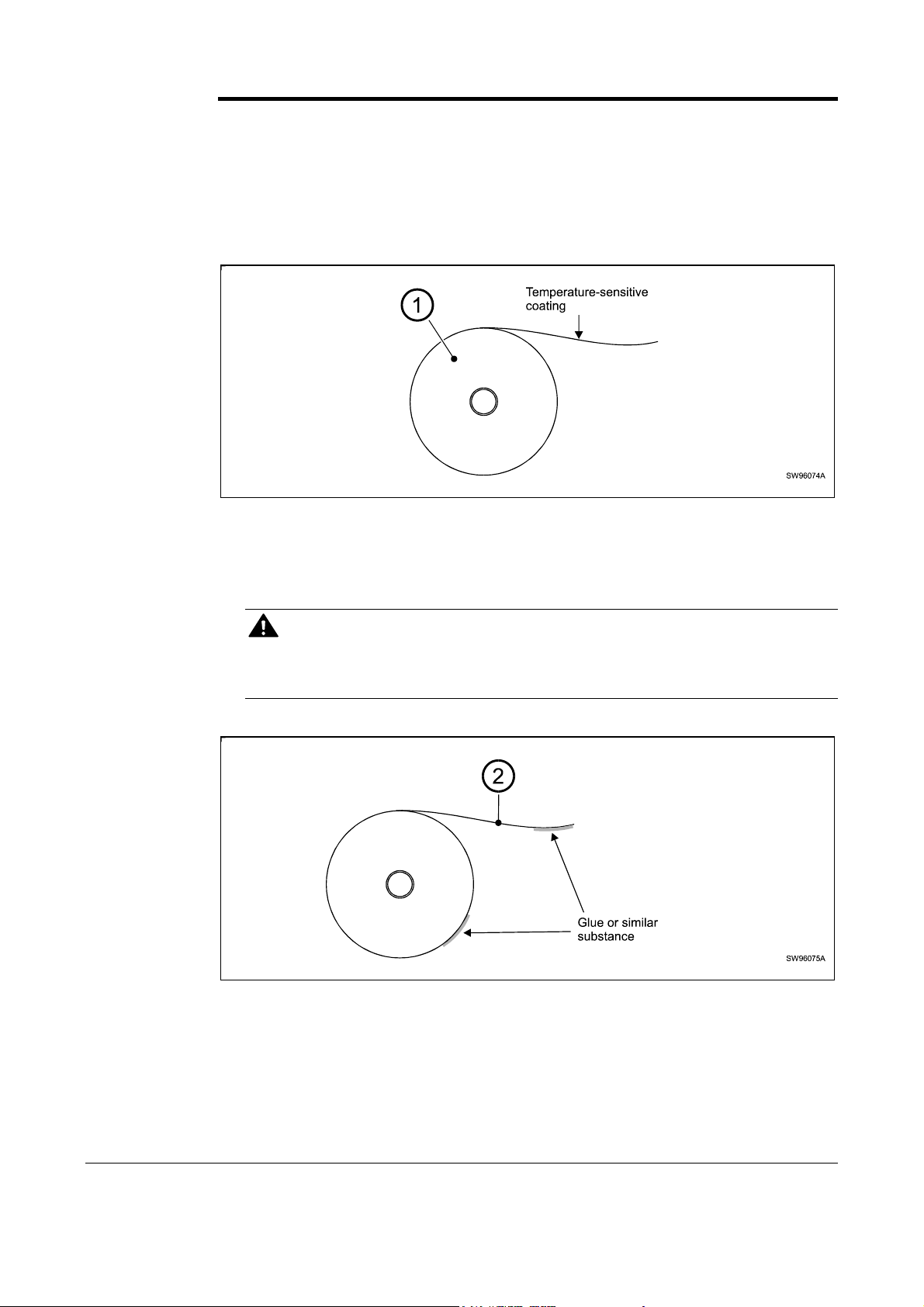
1. Turn the new paper roll as shown. The paper should be inserted into the printer with
the temperature-sensitive side up.
Figure 9. Turn the paper roll so that the paper leaves the roll from the top
2. Tear off a full turn of the paper (approximately 0.5 m) from the new paper roll.
CAUTION!
This is important since the outer end of the paper is usually fixed to the roll with some
type of glue or self-adhesive substance that might otherwise cause paper jam or even
printhead damage.
Figure 10. Tear off 0.5 m from the new paper roll
3. Make sure the printer is turned ON.
14 TTP 7000 Kiosk Printer – Technical Manual 0308
Page 15

4. Cut the paper in a suitable angle:
90
(Front Surface) (Front Surface)
To
70
Figure 11. Suitable paper edge for auto load
NOTE 1! — The paper sensor is at the same side as the blue paper release lever (where
the arrow points in Figure 12). If the paper is cut in a direction opposite to that as shown
in the figure above, the sensor will not detect the paper.
5. Insert the paper through the paper entry opening at the back of the printer. The
printer will now feed, cut and eject a receipt, and then automatically go on-line. 1
NOTE 2! — In high temperature and high humidity, the paper may lose its stiffness
resulting in paper jam at automatic paper loading. In such cases, load paper manually.
Figure 12. Insert the new paper
1
TTP 7000/112 was designed for manual paper loading. A modification of the control board is required for auto loading. Such
modification was introduced mid 2003. Auto loading was improved in firmware version 2.37 (see version history).
0308 TTP 7000 Kiosk Printer – Technical Manual 15
Page 16

4.2 Clearing paper jams
Should a paper jam occur, follow the procedure below:
1. Tear off the paper close to the paper roll and flip back the print module.
Figure 13. Flip open the print module
2. Lift the printhead by pushing the paper release lever upwards.
3. Remove any paper trash by gently pulling the paper up and out of the print module.
CAUTION! — Never
pull paper backwards through the print mechanism.
This may destroy the print module
Figure 14. Remove paper trash
16 TTP 7000 Kiosk Printer – Technical Manual 0309
Page 17

4.3 Self-test printout
1. Switch OFF the power.
2. Hold the feed-forward button depressed while powering ON the printer. Keep the
button depressed for at least 5 seconds.
This produces a printout showing the firmware program version and date, control board
revision number and serial number, name of loaded fonts and logotypes, parameter
settings, and the set printhead burn.
3. Each successive press of the button will produce a test printout.
4. Switch the printer OFF and ON again to exit self-test mode.
0308 TTP 7000 Kiosk Printer – Technical Manual 17
Page 18

5 PROGRAMMING
There are two completely different ways of setting up the receipt: Text oriented and driver
oriented style.
Text oriented
The receipt can be seen as the page of a simple word processor. You send text and
graphics to the printer, which prints the information in the same sequence as the data is
received. Design features are limited to the font stored in the flash PROM of the printer.
Text and logotypes can also be printed landscape orientation.
There are two text cursors, one for portrait, and one for landscape. The start positions of
the cursors are the upper left corner for the portrait cursor, and the upper left corner for
the landscape cursor, see Figure 15. You can switch between these cursors at any time,
the cursor will retain its last position on the ticket.
Driver oriented
When a Windows driver is used, you can use any Windows program to design the ticket
with text, graphics, bar codes or whatever you want to print and in any orientation you
want.
The Windows driver issues all the necessary commands. Only the cut-and-present and
black-mark commands need to be specified by the programmer.
Tex t r ec ei p t
Tex t
text
text
text text text text
text text text text
text text text text text text text text text text
text text text
text text text text text text text text text text
Text text text text text text text text text text
Driver (Windows) receipt
1 234567 890128
Text text
text text
text text
text text
text text
Text text text text text text text text text text
Bar codes can be added.
Text can be printed in
any orientation, font,
and size.
Lines can be added.
Graphics can be rotated,
color images converted
to gray scale, etc.
Sw98073
Figure 15. Ticket styles
18 TTP 7000 Kiosk Printer – Technical Manual 0308
Page 19

5.1 Summary of control codes & escape sequences
Command Hex Decimal Function Page
BS 08 008 Backspace
CAN 18 024 Cancel
CR 0D 013 Carriage return
EM 19 025 Enforced clear presenter
ENQ 05 005 Clear presenter
ESC ACK n 1B 06 n 027 006 Set acknowledge marker
ESC ! n 1B 21 n 027 033 Select font
ESC & 1 1B 26 01 027 038 001 Load logotype into flash PROM
ESC & 4 1B 26 04 027 038 004 Store current parameter values
in flash PROM
ESC & C 1B 26 43 027 038 067 Erase all fonts
ESC & D 1B 26 44 027 038 068 Erase fonts 4—7
ESC & L 1B 26 4C 027 038 076 Erase all logotypes
ESC & P n v 1B 26 50 n v 027 038 080 n v Set parameter values
ESC & NUL 1B 26 00 027 038 000 Load font
ESC ? 1B 3F 027 063 Reset (full)
26
36
27
34
34
42
29
36
36
37
37
36
37
36
36
ESC @ 1B 40 027 064 Reset (initialize)
ESC 3 n 1B 33 n 027 051 Line spacing
ESC b 0 x1 x2 y1 y2
ESC B n 1B 42 n 027 066 n Bold ON/OFF
ESC c n 1B 63 n 027 099 n Variable page length ON/OFF
ESC C n1 n2 1B 43 n1n2 027 067 n1 n2 Page length
ESC d n 1B 64 n 027 100 n Make n line feeds
ESC ENQ 01 1B 05 01 027 005 001 Status enquiry, general
ESC ENQ 02 1B 05 02 027 005 002 Paper-near-end enquiry
ESC ENQ 04 1B 05 04 027 005 004 Fonts and logotype enquiry
ESC ENQ 06 1B 05 06 027 005 006 Status report
ESC ENQ 07 1B 05 07 027 005 007 Firmware version enquiry
ESC ENQ 09 1B 05 09 027 005 009 Serial number enquiry
ESC ENQ 10 1B 05 0A 027 005 010 Control board revision enquiry
ESC ENQ 99 1B 05 63 027 005 099 Request device ID
ESC ENQ P 1B 05 50 027 005 080 Parameter setting data enquiry
1B 62 n… 027 098 n… Print bitmap at XY position
36
27
31
25
22
21
27
38
39
39
40
40
41
41
41
41
ESC f n 1B 66 n 027 102 n Presenter loop ON/OFF/length
0308 TTP 7000 Kiosk Printer – Technical Manual 19
35
Page 20

Command Hex Decimal Function Page
ESC F n1..nx NUL 1B 46 n1...nx 00 027 070 n...nx 000 Set horizontal tabs
ESC FF n 1B 0C n 027 012 n Eject (run presenter)
ESC g n1 n2 n3 n4 n5 1B 67 n1...n5 027 103 n1...n5 Print logotype at specified X, Y
ESC h n 1B 68 n 027 104 n Set multiple-height print
ESC i n 1B 69 n 027 105 n Italics ON/OFF
ESC J n 1B 4A n 027 074 n Paper advance
ESC j n 1B 6A n 027 106 n Paper reverse
ESC L n 1B 4C n 027 76 n Print logotype at current position
ESC M n1 n2 1B 4D n1n2 027 077 n1 n2 Black mark definition
ESC N n 1B 4E n 027 078 n Text alignment
ESC NUL 1B 00 027 000 Load firmware
ESC o n 1B 6F 027 111 Text and logotype orientation
ESC p 1B 70 027 112 Print
ESC q n 1B 71 n 027 113 n Print contrast adjustment
ESC RS 1B 1E 027 030 Cut only, no eject
28
34
32
29
25
32
32
33
23
24
37
24
32
33
34
ESC s n 1B 73 n 027 115 n Send dot line
ESC S n1 n2 1B 53 n1 n2 027 083 n1 n2 Send graphics data
ESC T n 1B 54 n 027 084 n Reversed text ON/OFF
ESC u n 1B 75 n 027 117 n Underline ON/OFF
ESC w n 1B 77 n 027 119 n Set multiple-width print
ESC V n 1B 56 n 027 086 n Print speed adjustment
ESC X n1 n2 1B 58 n1 n2 027 088 n1 n2 Sense black-mark position
ESC x n1 n2 1B 78 n1 n2 027 120 n1 n2 Set internal black-mark counter
ESC Z 1B 5A 027 090 Go to next top of form
FF 0C 012 Form feed
HT 09 009 Horizontal tabulation
LF 0A 010 Linefeed
RS 1E 030 Cut and eject paper
Table 3. Control codes & escape sequences in alphabetical order
31
31
29
29
29
32
23
23
23
28
28
27
34
NOTE! – In all responses from the printer the most
significant byte (MSB) is transmitted first.
20 TTP 7000 Kiosk Printer – Technical Manual 0308
Page 21

5.2 Software command syntax
The commands in this section are grouped after what they do, and these groups are
sorted in a theoretical usage sequence. It starts with commands for specifying the printed
page — through text-and-graphics commands — to cut-and-present commands. System
and status commands are presented at the end.
5.2.1 Page setup commands
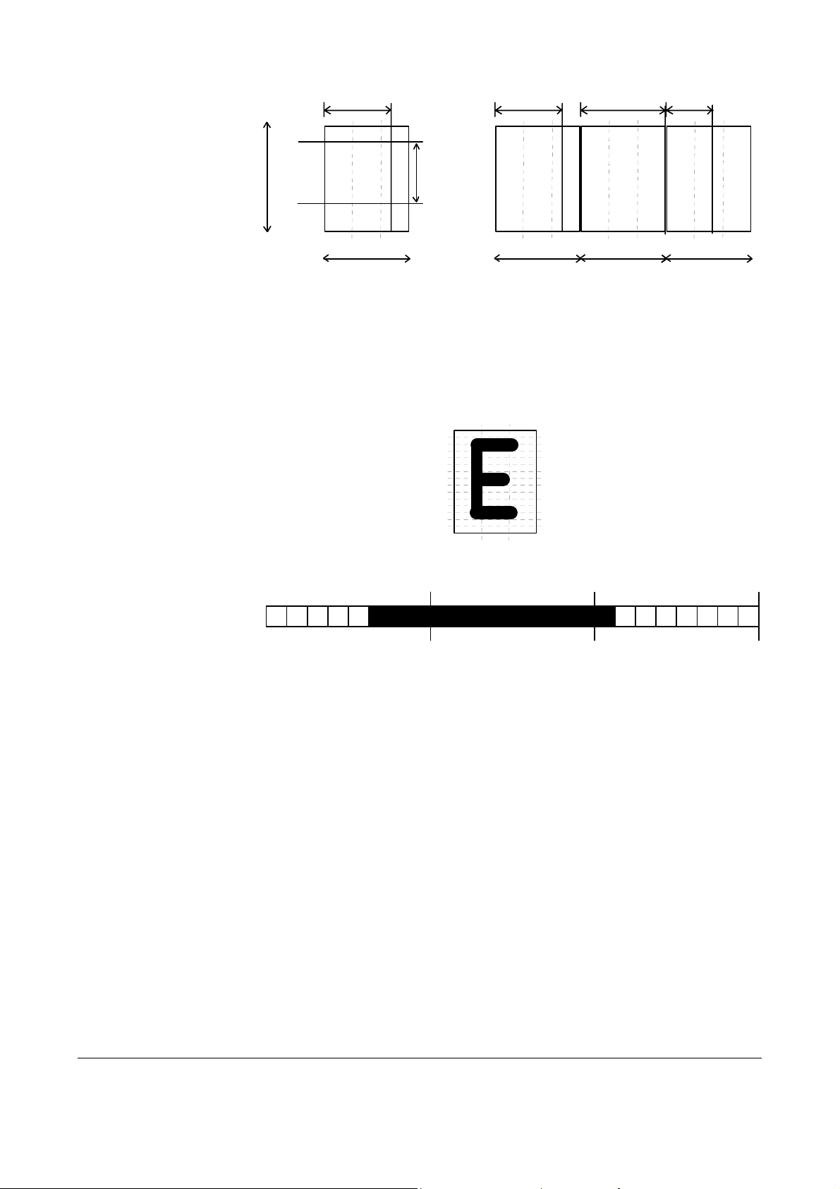
ESC C n1 n2
1B 43 n1 n2 hex
027 067 n1 n2 decimal
NOTE! — Use this command only when you want a fixed page
length. Shorter tickets will automatically be extended, while longer
tickets will be divided into several tickets of the desired length.
Set fixed page length
Top margin (Distance between cut and print line, 17 mm)
Page length
(minimum 75 mm)
Page width =
applicable print
window width
TEXT
Text text
Paper transport
direction
TEXT
Text text
SW97063-R2
Figure 16. Definition of page size
Sets the fixed page length expressed as a number of 0.125-mm pixel line-feeds. Form
feed is effected with the FF command.
NOTE! — Do not use fixed page length less than 75 mm (n1 = 2, n2 = 88)
• The ESC C n1 n2 setting applies unless superseded by command ESC c n that
enables the variable page length.
• Fixed page length settings, shorter than the minimum page length as defined by
default parameter settings, will automatically be adjusted to the default value.
NOTE! — To enable fixed page length you must also use ESC c 0,
see next page
0308 TTP 7000 Kiosk Printer – Technical Manual 21
Page 22

Example:
Length Command n1 n2 Length Command n1 n2
ESC c n
1B 63 n hex
027 099 n decimal
n = 0 OFF. Automatic form feed if the printed page length exceeds the
75 mm ESC C <002> <088>
80 mm ESC C <002> <128>
85 mm ESC C <002> <168>
90 mm ESC C <002> <208>
95 mm ESC C <002> <248>
100 mm ESC C <003> <032>
105 mm ESC C <003> <072>
110 mm ESC C <003> <112>
115 mm ESC C <003> <152>
120 mm ESC C <003> <192>
125 mm ESC C <003> <232>
130 mm ESC C <004> <016>
135 mm ESC C <004> <056>
140 mm ESC C <004> <096>
145 mm ESC C <004> <136>
150 mm ESC C <004> <176>
Table 4. Example of page length commands
Variable page length ON /OFF
length set by
ESC C n1 n2.
155 mm ESC C <004> <216>
160 mm ESC C <005> <000>
165 mm ESC C <005> <040>
170 mm ESC C <005> <080>
175 mm ESC C <005> <120>
180 mm ESC C <005> <160>
185 mm ESC C <005> <200>
190 mm ESC C <005> <240>
195 mm ESC C <006> <024>
200 mm ESC C <006> <064>
205 mm ESC C <006> <104>
210 mm ESC C <006> <144>
215 mm ESC C <006> <184>
220 mm ESC C <006> <224>
225 mm ESC C <007> <008>
230 mm ESC C <007> <048>
n = 1 ON. Selects continuous print mode (no auto FF). See also “Default
parameter settings”.
22 TTP 7000 Kiosk Printer – Technical Manual 0308
Page 23

5.2.2 Black-mark (top-of-form) commands
See also Aligning preprint and thermal print on page 52.
ESC M n1 n2
1B 4D n1 n2 hex
027 077 n1 n2 decimal
This command specifies maximum (n1) and minimum (n2) length (in transport direction)
of the black mark printed on the reverse side of the paper. The black-mark identifies the
top of the next form (document). The length of the mark is expressed in pixel lines of
0.125-mm height.
Active transition is from ”black” to ”white” (trailing edge of black-mark)
n1 Maximum valid value is 160 pixel lines (20.0 mm). Marks longer than this
n2 Minimum valid value is 15 pixel lines (1.9 mm). Marks shorter than this value
ESC X n1 n2
1B 58 n1 n2 hex
027 088 n1 n2 decimal
Looks for a black mark within the distance (paper transport) specified by n1n2, starting at
the current position.
n1n2 Specifies the distance to be searched for black-mark. n1 is the higher-order
Black mark size
value is interpreted as paper out. Default value = 80 pixel lines (10.0 mm)
is interpreted as dirt. Default value = 24 pixel lines (3.0 mm)
Locate black mark
and n2 the lower-order byte. The distance is to be expressed as a number of
0.125-mm steps.
The printer adds an error code in the status report (error, top of form, byte 1,
bit 3) if no black-mark is found within the specified distance.
ESC x n1 n2
1B 78 n1 n2 hex
027 120 n1 n2 decimal
ESC Z
1B 5A hex
027 090 decimal
Delay cut after black mark detection
n1n2 Sets the number of 0.125-mm steps to feed between the black mark
detection and the cut. n1 is the higher-order and n2 the lower-order byte.
At completed printout, an
ESC Z command effects paper feed until a black mark is
detected, that is, when black-to-white transition is detected at the trailing edge of the
black mark. The paper feed then continues the number of steps specified by n1n2, at
which point the correct cut-position is assumed.
Go to next black mark
Executes the number of pixel line feeds as defined by command ESC x n1 n2 minus
such pixel line feeds that have been effected after detection of black-mark.
NOTE! — If the black-mark has not passed the paper-out/blackmark sensor when the ESC Z is received, additional paper feed
(maximum 128 mm) takes place until a black-mark is detected.
0308 TTP 7000 Kiosk Printer – Technical Manual 23
Page 24

5.2.3 Text commands
Text received by the printer is printed with the currently selected font and font attributes.
Text exceeding the page width is wrapped with the line spacing selected.
ESC o n
1B 6F n hex
027 111 n decimal
Changes the orientation of text and logotypes.
n = 0 Gives portrait orientation
n = 1 Gives landscape orientation
Portrait and landscape can be mixes on the same receipt. There are two cursors, one for
portrait and one for landscape. The cursor always starts at the top left corner of the
document. Looking at the paper when it exits the printer, the portrait cursor is at the top
left corner of the receipt, moving to the right as text is typed, while the landscape cursor is
at the top right corner, moving downwards.
NOTE! — Landscape only works if fixed page length is used. Start a
page by specifying page length for example <ESC>C<003><032>,
then turn off auto page length with <ESC>c<000>
NOTE! — ESC o <001> and ESC o <000> must be on separate lines
(separated by a linefeed <LF>).
ESC N n
1B 4E n hex
027 078 n decimal
Changes the alignment of text and logotypes.
Text and logotype orientation
Text alignment
ESC N 0= Left ESC N 1 = Center ESC N 2 = Right
ESC ! n
1B 21 n hex
027 033 n decimal
This command selects one of eight fonts. The font design depends on which fonts have
been loaded
1
into the printer. Make a test printout to see which fonts are available in your
printer.
ESC ! 0 selects normal font (font 0) ESC ! 4 selects font 4
ESC ! 1 selects font 1 ESC ! 5 selects font 5
ESC ! 2
ESC ! 3 selects font 3 ESC ! 7 selects font 7
selects font 2 ESC ! 6 selects font 6
Lines, too long to be printed in the selected font, are automatically wrapped around.
Different fonts can be used on the same line.
1
For font loading, see " " on page 36 System related commands
Select font
Table 5. Font selection commands
24 TTP 7000 Kiosk Printer – Technical Manual 0308
Page 25

Selection of an erased or for any other reason non-existent font, will set bit 4 of byte 1 in
the status enquiry response to ”1". See “Parameter setting data enquiry” on page 41.
NOTE! — If more than 256 characters are sent to the printer before an LF,
the first part of the buffer contents is printed-out automatically. The text is
formatted according to the already received formatting commands.
ESC B n
1B 42 n hex
027 66 n decimal
ESC i n
1B 69 n Hex
027 105 n decimal
ESC T n
1B 54 n hex
027 084 n decimal
ESC u n
1B 75 n hex
027 117 n decimal
Bold Normal Bold
n = 0 Turns OFF bold (Normal)
n = 1 Turns ON bold
Bold is designed for normal character width and shows less and less as the width
increases.
Italics Normal Italics
n = 0 Turns OFF Italics (Normal)
n = 1 Turns ON Italics
Reversed print ON/OFF
Selects normal or reversed print.
n = 0 Gives normal print, black on white
n = 1 Gives reversed print, white on black
Single words, characters, or complete text lines can be reversed.
Underline
n = 0 Turns OFF underline
n = 1 Turns ON a 1 pixel wide underline
n = 2 Turns ON a 2 pixel wide underline, etc. up to n=7.
Single words, characters, or complete text lines can be underlined.
0308 TTP 7000 Kiosk Printer – Technical Manual 25
Page 26

ESC h n
1B 68 n hex
027 104 n decimal
Applicable n values are 000 — 015.
n = 1 Increases the character height to 2 times the basic character height.
n = 2 Increases the character height to 3 times the basic character height etc.
n = 0 Resets the character height to the basic character height.
In combination with variable character width (
depending on the font to which the command has been applied.
Different fonts and heights can be mixed on the same print line.
ESC w n
1B 77 n hex
027 119 n decimal
Applicable n values are 000 — 007.
n = 1 Increases the character width to 2 times the basic character width.
n = 2 Increases the character width to 3 times the basic character width etc.
n = 0 Resets the character width to the basic character width.
In combination with variable character height (
depending on the font to which the command has been applied.
Set multiple-height print
ESC w n), give highly legible characters
Set multiple-width print
ESC h n), give highly legible characters
Different fonts and widths can be mixed on the same print line.
ESC t n1 n2 n3 n4 n5 data
1B 74 n1 n2 n3 n4 n5 data hex
027 116 n1 n2 n3 n4 n5 data decimal
Prints a text string at the specified X-Y position. The string will use the formatting set by
font, reversed, width, height, bold and underline commands.
n1n2 Two byte definition of the X print position (in pixels).
n3n4 Two byte definition of the Y print position (in pixels).
n5 The number of characters in the string.
data The text string. The length must be exactly the number of characters specified by
n5, otherwise the printer will stop, waiting for more characters.
After the string has been printed, the cursor will return to the position it had before the
string command was issued.
NOTE! — The Y print-position only works if fixed page length is used.
Start a page by specifying page length for example
<ESC>C<003><032>, then turn off auto page length with <ESC>c<000>
BS
05 hex
005 decimal
Moves the print-position one step to the left. Backspace can be used to combine
characters. For instance to print a Ø, send text commands O BS / to the printer, and the
slash will overprint the O.
Print text string
Back Space
Only one backspace can be used at a time. Excessive backspaces will be ignored.
26 TTP 7000 Kiosk Printer – Technical Manual 0308
Page 27

CAN
18 hex
024 decimal
CR
0D hex
013 decimal
LF
0A hex
010 decimal
Cancel
Cancels print data on the same line as the command itself. ESC commands, issued on
the same line as the CAN command, are not cancelled.
Carriage Return
Carriage return is ignored by default.
By changing the default settings, you can:
• Interpret is as
• Interpret
(see command
CR. This returns print position to beginning of line without line feed.
CR as CR/LF. This inserts line space as specified by the line spacing setting
ESC 3 n on page 27), and returns the print position to beginning of
the line.
See “Carriage return and line feed behavior ” on page 48.
Linefeed
Linefeed is interpreted as CR/LF by default. This inserts line spaces as specified by the
line spacing setting (see command
beginning of the line.
ESC 3 n on page 27), and returns the print position to
By changing the default settings, you can:
• Interpret
• Ignore
See “Carriage return and line feed behavior ” on page 48.
ESC d n
1B 64 n hex
027 100 n decimal
Executes the number of linefeeds as defined by variable n. The length of each line feed is
determined by.
• the default value for selected font (see command
• the line setting effected by command ESC 3 n, (n = ”0” gives no line feed)
The print position is returned to the beginning of the line. Any text on the line is lost. To
avoid loosing text, send an LF before sending ESC d n.
ESC 3 n
1B 33 n hex
027 051 n decimal
This command is used to increase the line spacing. The entered value n is the absolute
line spacing expressed as a number of pixel lines (0.125-mm increment). To increase the
line spacing to 5 mm, for example, enter value n = 40 (5 / 0.125 = 40).
LF as Linefeed. This inserts line space as specified by the line spacing
setting (see command
ESC 3 n on page 27), without returning the print position to
the beginning of the line.
LF.
Execute n linefeeds
ESC 3 n on page 27) or
Set line spacing
The command is ignored if “n” is less than the default line spacing of the selected font.
The default line spacing is directly related to the size of the selected font.
0308 TTP 7000 Kiosk Printer – Technical Manual 27
Page 28

Examples: 10 cpi 30 pixels = 3.75 mm 15 cpi 20 pixels = 2.5 mm
12 cpi 24 pixels = 3.0 mm 17 cpi 18 pixels = 2.25 mm
Double-height text on a line will double the line spacing for the entire line.
FF
0C hex
012 decimal
HT
09 hex
009 decimal
Form Feed
Prints data from the input buffer and feeds the paper to the top of the next page.
• In fixed document length (FORM-mode) this command prints data in the input buffer
and feeds the paper to the top of next page.
• In variable document length mode this command acts as
• In black-mark mode, the printer interprets incoming
CR/LF.
FF commands as ESC X 08 00
If Autocut at FF is set to 1 (in start-up parameter setting ESC & P n34), FF effect both
form-feed, cut, and eject.
NOTE! — Use
ESC C n1 n2 to define page length.
Horizontal Tabulation
Shifts the current print position to the next Tab position.
Set tab positions with the ESC F n1....nx command on page 28.
ESC F n1 ... nx NUL
1B 46 n1 ... nx 00 hex
027 70 n1 ... nx 000 decimal
This command defines the desired horizontal tab positions. Variables n1...nx represent
each tab position. Up to 16 tab positions are allowed. Minimum allowed value is “1”.
Tab position 255 sets a tab stop on the last position of the line. Use this if you want
underline or reversed text to extend across the full paper width.
Note that the tab positions are always expressed in number of 2.5-mm steps.
n = 1 Means 2.5 mm from the left-hand edge of the print window.
EXAMPLE
Send→ ESC F 005 010 015 020 025 000
Sets tab stops at 12.5, 25, 37.5, 50, and 62.5 mm.
NOTE! — Do not use value n = 0. The values must
be sorted from low to high numbers.
Set horizontal tabs
28 TTP 7000 Kiosk Printer – Technical Manual 0308
Page 29

5.2.4 Barcode commands1
ESC BC n
1B 42 43 n hex
027 067 068 n decimal
Clears the bar code field reserved by command ESC BS.
n Specifies which bar code field to clear. The range is 0 to 15. The fields may be
cleared in any order.
ESC BS n1 ... nx NUL
1B 42 53 n1 ... n11 00 hex
027 66 83 n1 ... n11 000 decimal
Bar codes can only be printed in portrait mode unless fixed page length is selected.
The command reserves an information field as a bar code field. The command also
identifies the type, number of digits, and the configuration of bars to be placed in the bar
code field.
n1 Specifies the bar code field No. (0—15). Bar code fields may be specified in any
order.
n2n3 Sets the X coordinate of the bar code field origin (n2 is the higher-order and n3
the lower-order byte).
n2 and n3 must be 1-byte hexadecimal or decimal numbers. The values must not
place the bar code outside the total pixel count that can be handled by the printer.
n4n5 Specifies the Y coordinate of the bar code field position, (n4 is the high, and n5
the lower-order byte).
Barcode Clear
Barcode field Specify
n4 and n5 must be 1-byte hexadecimal or decimal numbers.
n6 Specifies the number of bar code digits, but is ignored by the printer.
n7n8 Specifies the height of the bars.
n9 Specifies the type of bar code. The following types are supported.
n10 Specifies the thickness of the narrow bar 0=1 pixel, 1=2 pixel, and so on.
n11 Specifies the wide-bar-to-narrow-bar ratio. Only used in Code 39 and 2-of-5
ESC BW n1 nx
1B 42 57 n1 nx hex
027 066 087 n1 nx decimal
Writes data to the bar code field reserved by the ESC BS command.
1
Introduced in firmware version 2.31
n9 = 0 EAN 8 or 13 (auto detect). The printer calculates the necessary check
digit.
n9 = 1 UPC
b9 = 2 2/5 Interleaved (even number of characters must be sent)
n9 = 3 ISBN
n9 = 6 Code39
interleaved where different ratios are allowed.
Barcode Write
0308 TTP 7000 Kiosk Printer – Technical Manual 29
Page 30

n1 Specifies the field No. Range 0 to 15. Fields can be specified in any order
but other values than 0 to 15 are ignored.
n2 . . . nx Specifies bar code data bytes.
To create a bar code add-on, insert a space character and then the data for
the add-on.
NUL must be placed at the end of the bar code data.
Any invalid bar code character terminates the command.
5.2.5 Example:
<ESC>BS<h00><h00><h78><h00><h00><h0C><h00><h50><h00><h02><h00>«»
<ESC>BW<h00>733104000099<h00>«»
<RS>«»
Will print one barcode with height = 10 mm and moved 15 mm to the right
30 TTP 7000 Kiosk Printer – Technical Manual 0308
Page 31

5.2.6 Graphics commands
ESC S n1 n2 data
1B 53 n1 n2 data hex
027 083 n1 n2 data decimal
Sends bit image graphics data to the printer.
n1 and n2 High and low order byte. Determine the number of dot lines.
<data> If less data than specified is received, the printer may enter a wait state,
ESC s n
1B 73 n hex
027 115 n decimal
Sends one line of dot data. This command is used to build images, one dot line at a time.
n Determines the number of bytes.
<data> 1–72 bytes of data for 80 mm printer, 1–104 bytes for 112 mm printer
Send graphics data
expecting further data. The printer may handle subsequent character
code, or non-bit-image data, as bit-image data. The host computer must
therefore supply 72 x (n1n2) data bytes for the 80 mm printer, and
104 x (n1n2) data bytes for the 112 mm printer, that is, 72 alternatively
104 bytes per line times the number of dot lines to be printed.
Send dot line
• If less than 72 or 104 bytes are sent, the printer will fill the rest of the
dot line with spaces.
• If more than 72 or 104 bytes are received, the rest of the bytes are
ESC b n1 x1 x2 y1 y2 data
1B 62 n1 x1 x2 y1 y2 data hex
027 98 n1 x1 x2 y1 y2 data decimal
Prints a black & white Windows bitmap at the specified X-Y position. The bitmap must be
a complete Windows bitmap (BMP-file) where the data starts with BM.
n1 Always 0
x1x2 Two byte definition of the X print position (in pixels).
y1y2 Two byte definition of the Y print position (in pixels).
data Bitmap data.
After the bitmap has been printed, the cursor will return to the X-position that it had before
the bitmap command was issued.
Selecting horizontal mode (with ESC o 0) prints the image in portrait orientation, while
selecting the vertical mode (with ESC o 1) prints the image in landscape orientation.
NOTE! — The Y print-position and horizontal/vertical orientation only
works if fixed page length is used.
Start a page by specifying page length for example
<ESC>C<003><032>, then turn off auto page length with <ESC>c<000>
discarded.
Print bitmap image
0308 TTP 7000 Kiosk Printer – Technical Manual 31
Page 32

5.2.7 Print commands
ESC p
1B 70 hex
027 112 decimal
This command makes the printer print the contents of the line buffer.
Text is converted from text to pixel lines and stored in the line buffer when an LF is
received. If the line buffer is empty when ESC p is received, nothing is printed.
Text to be printed <LF><esc>p prints "Text to be printed" on the paper.
Printout is effected automatically at:
Cut (
Clear presenter (
Run presenter (
Print buffer full When print data for approximately 0.75 m receipt length has been
ESC J n
1B 4A n hex
027 074 n decimal
The value n represents the number of dot lines (0.125 mm) the paper is to be transported
forwards. Maximum value for n = 255, equal to approximately 32 mm.
Print
RS and ESC RS)
ENQ)
ESC FF n)
received (0.5 m for TTP 7000/112)
Paper advance
ESC j n
1B 6A n hex
027 106 n decimal
The value n represents the number of dot lines (0.125 mm) the paper is to be transported
backwards. Maximum value for n = 255, equal to approximately 32 mm.
ESC V n
1B 56 n hex
027 086 n decimal
n specifies the printing speed. The main reason to decrease the print speed
NOTE! — Some settings result in printer chassis resonance
causing excessive noise and deteriorated print quality.
mm/s
Paper reverse
Print speed adjustment
is to enhance print quality, and to reduce the peak current consumption.
n = 17 is default value (maximum speed)
0 1 2 3 4 5 6 7 8 9 10 11 12 13 14 15 16 17
n
13 21 27 32 37 41 45 48 52 55 57 60 63 66 68 71 73
Table 6. Print speed settings
75
32 TTP 7000 Kiosk Printer – Technical Manual 0308
Page 33

ESC q n
1B 71 n hex
027 113 n decimal
n = 0–15
This command adjusts the burn time to obtain the optimal print contrast with the paper
quality in use.
Each step n represents a pulse width adjustment of 5%. The actual burn time depends
on ambient temperature and heat built up in the head.
Example:
ESC q 0: 75% pulse width
ESC q 5: 100% pulse width (default)
ESC q 15: 150% pulse width
At power ON, the contrast is set to the value stored as default parameter. See page 47.
ESC L n
1B 4C n Hex
027 076 n Decimal
Prints a customized logotype1 stored in the flash PROM at the position of the cursor. The
bottom line of the logotype is positioned at the baseline of the text on the line. If the
logotype is higher than the text, the line spacing is increased.
Print contrast adjustment
Print logotype at current cursor position
See also Logotypes on page 45.
n One-byte logotype identification No. (0—15)
ESC g n1 ... N
1B 67 n1 ... N5 hex
027 103 n1 ... N5 decimal
5
Prints a customized logotype1 stored in the flash PROM. See also Logotypes on page 45.
n1 One-byte logotype identification No. (0—15)
n2n3 Two-byte definition of desired print position in X-direction (expressed in
n4n5 Two-byte definition of desired print position in Y-direction expressed in pixels
Print logotype at specified X–Y
pixels) measured from left-hand edge of the page (see page 21 regarding
definition of ”page”). X-direction is perpendicular to the paper transport
direction.
from top of the page.
These bytes must always be inserted but they are ignored in variable-
page-length mode where logotypes are always printed at the current Yposition.
1
For logotype loading, see " " on page 36 System related commands
0308 TTP 7000 Kiosk Printer – Technical Manual 33
Page 34

5.2.8 Cut and present commands
RS
1E hex
030 decimal
Effects a paper cut-off and a default-length eject through the presenter module.
If the receipt length is too short, paper-feed is added until the 75-mm minimum receipt
length is reached, before execution of the Cut command.
ESC RS
1B 1E hex
027 030 decimal
Effects paper cut-off only.
Eject can be effected with the
If the receipt length is too short, paper-feed is added until the 75-mm minimum receipt
length is reached, before execution of the Cut command.
ESC FF n
1B 0C n hex
027 012 n decimal
ESC FF ejects the document through the presenter module. Variable n represents the
number of eject-steps.
One step is approximately 2 mm
The maximum number of steps is 255
Normally, this command is placed after a cut command (
receipt to the customer. Set the number of eject steps so that a small part of the receipt is
retained in the presenter module, avoiding that the receipt drops to the floor.
Cut and eject receipt (record separate)
Cut only, no eject
ESC FF n command (see page 34).
Eject (run presenter)
ESC RS) to partially eject the
ENQ
05 hex
005 decimal
EM
19 Hex
025 Decimal
Another use of the command is to eject a part of a long document without preceding cut.
The reason to do this is to limit the size of the loop build-up in the presenter.
NOTE! – The loop is limited to the value set by
ESC f n to avoid paper
jam. The default setting of n=18, gives a loop of just above 0.5 m. When
this length has been looped, the printer presents that part of the receipt.
Then, without cutting the paper, it continues to print the rest of the
receipt.
Clear presenter
Clears the paper path in the presenter, for example, to eject a document not removed
during the previous print/cut/eject operation.
Enforced Clear Presenter
Same function as ENQ but overrides the Retract and Retain parameter (p45) with another
presenter behavior. The function of n can be 0 or 100 (se the description of parameter
45). The command will clear the presenter immediately (with printing synchronization).
34 TTP 7000 Kiosk Printer – Technical Manual 0308
Page 35

ESC f n
1B 66 n hex
027 102 n decimal
Presenter loop ON/OFF/max length
n = 0 Presenter sensor is ignored. The paper is fed straight through the presenter.
range 0 and 3 to 255. n = the loop length limit in 3.2 cm steps.
If the receipt length exceeds the max loop limit, it is partially ejected before the
printer continues.
n = 18 Default setting which gives a loop of just above 0.5 m.
Can be turned ON/OFF at any time during an operation.
0308 TTP 7000 Kiosk Printer – Technical Manual 35
Page 36

5.2.9 System related commands
ESC ?
1B 3F hex
027 063 decimal
ESC @
1B 40 hex
027 064 decimal
ESC & 1
1B 26 01 hex
027 038 001 decimal
ESC & L
1B 26 4C hex
027 038 076 decimal
Reset (full)
Restarts the printer with a complete reset.
Reset (initialize)
Terminates the processing and initializes the control board. The control board is reset to
default-values (same as after power ON). Do not use this command as part of a print data
command string.
Load logotype
Stores a logotype bitmap in the flash PROM. The logotype is printed with the ESC g
command, see page 32. Also see Logotypes on page 45.
Erase all logotypes
Erases all logotypes stored in the flash PROM.
NOTE! — This command is only executed if all these conditions are met:
• At least one logotype has been loaded
• Status inquiry response byte 1, bit 5, ”Power has been OFF” is set to ”1”
• No
ESC & 4
1B 26 04 hex
027 038 004 decimal
Stores all parameter values, currently in use in the printer, as permanent default
parameter values in the flash PROM. This takes approximately 15 seconds. The printer
then resets automatically and activates the presenter motor temporarily.
See also
ESC & NUL
1B 26 00 hex
027 038 000 decimal
This command is used to load a font to the printer flash PROM. The font is placed in the
first free address position in the order of load sequence.
A Swecoin font-file consists of a header containing data describing the font as well as
data for each individual character in the font.
ESC ENQ 6 command has been received
Store current parameter values in flash PROM
ESC & P (Set temporary default parameters) on page 37.
Load font
1
1
When parallel cable is connected, both printer and host computer must have
been off to set this bit. This is because the interface powers the RAM in the
printer.
36 TTP 7000 Kiosk Printer – Technical Manual 0308
Page 37

Fonts can be designed with the font editor and loaded or deleted with the software
available for free on the Swecoin web site. The font loading and deleting commands
described here should only be used if you do not work in the Windows environment.
For complete specification of the font format, see Font loading on page 43.
NOTE! 256 Kbytes are available for font storage. A maximum of 8 fonts can be
addressed. Exceeding any of these limits will cause this command to fail.
ESC & C
1B 26 43 hex
027 038 067 decimal
Erases all fonts stored in the flash PROM.
NOTE! — This command is only executed if all these conditions are met:
• At least one font has been loaded
• Status inquiry response byte 1, bit 5, ”Power has been OFF” is set to ”1”
• No
ESC & D
1B 26 44 hex
027 038 068 decimal
Erases fonts number 4–7. Fonts 0–3 are not affected by this command.
The operation is complete when the printer resets automatically and activates the
presenter motor temporarily. Takes approximately 15 seconds.
ESC & P n v
1B 26 50 n v hex
027 038 080 n v decimal
A number of bytes in the flash PROM hold various parameter values called default
parameters. One or several of them can be overridden temporarily with this command.
Erase all fonts
ESC ENQ 6 command has been received
Erase fonts 4–7
Set temporary default parameters
n Parameter number
v Parameter value.
See Default parameter setting on page 47.
The permanently stored parameters will be used again after a printer-reset command or
at power ON.
The temporary values can, however, be stored in the flash PROM as permanent values
with command
ESC & 4.
ESC NUL
1B 00 hex
027 000 decimal
Load firmware
This command should only be used when loading new firmware into the printer. See also
Firmware on page 67.
0308 TTP 7000 Kiosk Printer – Technical Manual 37
Page 38

5.2.10 Status reporting commands
See also Status reporting on page 41.
NOTE! – The status commands are immediate, that is they are executed exactly when
they are received. This means they pass the print queue in the printer and may be
executed before other commands.
ESC ENQ 1
1B 05 01 hex
027 005 001 decimal
A status enquiry results in response ACK (06 decimal) if all sensors are clear, but NAK (15
decimal) + code if one or more sensors report fault condition.
Status enquiry
Error code Meaning
ACK OK (printer is operable)
NAK 01 Paper left in presenter module. Attempt to clear the paper path failed.1
NAK 02 Cutter not in home position
NAK 03 Out of paper
NAK 04 Printhead lifted
NAK 05 Paper-feed error. No paper detected in presenter although 10 cm has been
printed. Paper might be wound around the platen or, in some way, has been
forced above the presenter module.
NAK 06 Temperature error. The printhead temperature has exceeded the 80 °C
maximum limit.
Table 7. Error codes
NOTE! — Errors 2, 5, and 6 are terminal faults that require you to reset
the printer before it will be operable again. The printer automatically
recovers from the other error conditions as soon as the error is corrected.
A status enquiry command can only return one status code at a time. If there are two or
more simultaneous errors, each error condition should be cleared and the status enquiry
repeated in order to get a complete report of all status codes.
The host computer cannot be certain that all error conditions have been cleared until an
ACK is received.
The possible error conditions are reported in the above order.
1
The printer will answer ACK even if paper is present in the presenter unless you send a clear presenter command first, and
that command fails. To get an immediate sensor status reply, use ESC ENQ 6 instead and look at bit 3 in the second byte.
38 TTP 7000 Kiosk Printer – Technical Manual 0308
Page 39

ESC ENQ 2
1B 05 02 hex
027 005 002 decimal
This command requests a paper-near-end sensor (paper low) status from the printer in a
1-byte format.
Value = (01H) indicates ”No paper”
Value = (00H) indicates ”Paper present” at the sensor position
NOTE! – The status of the sensor is sampled every time the receipt is cut. If three
succeeding samples show "no paper", the status reply changes to 00. This is to
prevent false alarm if the side of the paper roll is not clean. If you want the
momentary status of the sensor, use
ESC ENQ 4
1B 05 04 hex
027 005 004 decimal
Requests multiple bytes of information regarding loaded fonts and logotypes.
EXAMPLE (↵ = CR LF)
Send→ ESC ENQ 004
Read←
0:9632 Courier 13↵
1:12612 Ariel 12
2: ↵
3: ↵
4: ↵
5: ↵
6: ↵
7:
Free font memory:246122↵
00: ↵
01: ↵
02: ↵
03:14 110 Recycle↵
04:
05:103 65 Warning
06:
07: ↵
08:
09: ↵
10:
11: ↵
12:
13:
14: ↵
15: ↵
16:
Free logotype memory:189512↵
↵
↵
↵
↵
↵
↵
↵
↵
↵
↵
Paper-near-end enquiry
ESC ENQ 6 and extract the paper-near-end bit.
Font and logotype enquiry
The response begins with 8 lines of
font data containing font numbers,
font sizes in bytes, font names, and
font height in pixels.
Remaining font memory in bytes.
16 lines of logotype data containing
logotype number, with and height of
the logotype in pixels, and logotype
name.
Remaining logotype memory in bytes
0308 TTP 7000 Kiosk Printer – Technical Manual 39
Page 40

ESC ENQ 6
1B 05 06 hex
027 005 006 decimal
Results in a 2-byte response, reflecting the status of each sensor. This command is
intended as a go/no go indication. When everything is OK, this status report returns 0.
NOTE! – If no weekend sensor is installed, 64 is returned when everything is OK. If
no weekend or paper-near-end sensors are installed, 64+2=66 is returned when OK.
Status report
First byte, bit No.: Second byte, bit No.:
7 6 5 4 3 2 1 0 7 6 5 4 3 2 1 0
Weekend sensor
Head lifted
Cutter not home
FF button pressed
Paper at presenter
-
-
-
Print data exists**
Pending error code*
Power has been OFF***
Error Black Mark
Software error****
Table 8. Sensor status
Retract unit fitted
Out of paper
Paper-near-end*****
* This bit indicates that an error code is available. Use ESC ENQ 1 to fetch it.
** This bit tells you that there are data in the printer that have not yet been printed. There
*** When parallel cable is connected, both printer and host computer must have
**** Trying to select non existing font or other error
***** This paper-near-end bit differs from the ESC ENQ 2 response, see page 39.
Bits 3 to 5 in the first byte are reset when they are read.
ESC ENQ 7
1B 05 07 hex
027 005 007 decimal
Results in a 2-byte response representing the version of the installed firmware.
The first byte represents major versions, and the second byte minor versions.
EXAMPLE
are two possible reasons for that:
1. The last command received by the printer was not a command that triggers a printout.
2. The printer is printing
been off to set this bit. This is because the interface powers the RAM in the
printer.
Firmware version enquiry
Send→ ESC ENQ 007
Read←
<001><020>
That is, a response with the value <001><020> indicates version 1.20.
40 TTP 7000 Kiosk Printer – Technical Manual 0308
Page 41

ESC ENQ 9
1B 05 09 hex
027 005 009 decimal
Results in a 6-byte response representing the serial number.
EXAMPLE
Send→ ESC ENQ 009
Read←
00h 00h 02h 2Bh C6h 28h (hex), or 000 000 002 043 198 040 (dec)
ESC ENQ 10
1B 05 10 hex
027 005 010 decimal
Results in a 1-byte response representing the control board revision. A minus sign
indicates that no revision has been made, while A indicates the first revision, and so on.
EXAMPLE
Send→ ESC ENQ 010
Read←
n Where n can be ‘A’ (ASCII) or41h (hex) or 065 (dec)
ESC ENQ c
1B 05 63 hex
027 005 099 decimal
Results in a string containing the device ID in the Windows Plug and Play string format.
The two first bytes represent the string length.
Serial number enquiry
Control board revision enquiry
Request device ID
EXAMPLE
Send→ ESC ENQ 099
Read←
000 106 This indicates that the string is 104 characters (plus two characters indicating
Read← ”MANUFACTURER:Swecoin AB;COMMAND SET:None;MODEL:TTP7000;CLASS:PRINTER;
DESCRIPTION:Ticket Printer TTP7000;”
NOTE! – The read string above is just an example.
Read out the actual string from your printer.
ESC ENQ P n
1B 05 50 n hex
027 005 080 n decimal
This command requests information about the setting of parameter n, that is, the
parameter value stored in flash PROM or any parameter value temporarily set by other
ESC commands. Parameter names (n) are listed on page 48.
the string length)
Parameter setting data enquiry
0308 TTP 7000 Kiosk Printer – Technical Manual 41
Page 42

ESC ACK n
1B 06 n hex
027 006 n decimal
n = One-byte marker. Range 0 to 255
The "acknowledge marker" n is placed in the command queue and when the execution of
commands reaches the marker it is sent back to the host computer. This is an addition to
the status commands that pass the queue and are answered immediately when received.
EXAMPLE:
"Print data" <ESC><ACK><001>"Cut & Eject" <ESC><ACK><002>
The printer will send
has been performed.
NOTE! — Acknowledge marker cannot be used for events that write to the flash PROM,
for instance font loading. This is because the writing procedure erases the buffer,
including the markers, and uses all RAM in the printer.
Set acknowledge marker1
<001> when <print data> has executed and <002> when the ejecting
1
Added in firmware version 2.29b
42 TTP 7000 Kiosk Printer – Technical Manual 0308
Page 43

5.3 Font loading
The printer can store 8 fonts in its flash PROM. 256 kB are available for font storage. The
font size is fixed1, so you must load one font file for each character size you require. The
fonts are given font numbers when they are loaded into the printer. The first font is
assigned number 0 and the next font 1 etc. up to font 7. The font number parameter
number14 of the default parameter setting will be used when no font selection command
has been received (see page 47).
You cannot erase a single font, but must erase font 4-7 with command
ESC & D, or all
eight fonts with ESC & C, then reload the fonts you wanted to keep.
Windows software for font generation and management is available on the Swecoin web
site. If you need to load fonts in a non-Windows environment, use the
ESC & NUL
command.
The time required for processing the font data that is loaded is typically 15–20 seconds
per font, excluding transfer time. During this time, any data sent to the printer will be lost.
NOTE! — The font processing is ends with a reset. The presenter motor runs
momentarily to indicate that the printer is ready to be used.
CAUTION! — Loading to the flash PROM will erase the RAM completely since the RAM
is used during the loading process. Any print data residing in RAM will thus be lost.
5.3.1 File format
A font consists of a header describing the font, then data for every character in the font.
The header has to be downloaded even if the font consists of a single character only.
Below is a description of the font header.
1 byte Reserved Should always be 0 (zero)
1 byte Reserved Should always be 0 (zero)
1 byte Char. width (X) The number of bytes required for the width of one character,
usually 2 or 3. Range 1 to 8.
1 byte Character pitch The maximum width of one character in the set. This value is
used for tab position calculation. Range 1 to 255.
1 byte Char. height (Y) The maximum height of one character matrix measured in
pixels. This is also the minimum line spacing for this
character set.
27 byte Font name String of characters used to identify the character set.
This will be printed on status receipts. (E.g. Swiss 10 cpi.)
Char_matrix table: 256 records, each containing 3 bytes.
3 byte Char_width (pixels) + Char_Ystart(pixels) + Char_Yheight(pixels)
Char_bitmap data: Bitmap data for all characters that are to be defined.
1
Multiple height, and width commands can be used on all fonts.
0308 TTP 7000 Kiosk Printer – Technical Manual 43
Page 44
Char_width
Char_Ystart
Char_width
Char_width
Char_width
Char_sizeY
Baseline
Character bitmap data:
A character is made up of a bitmap the size of which is:
Char. width (X) * Char. Height (Y) bytes.
MSB LSB MSB LSB
A
Char_sizeX
Col 0 Col 1
Char_Yheight
A
Char_pitch
COLUMN
012
0
4
ROW
W
Char_pitch
Col 2
MSB LSB
g
Char_pitch
Row 1
=03H =FFH =80H
The bitmap data consists of bitmap patterns for each character in a character set for
which the parameter Char_width in the Char_matrix table is set to a value between 1 and
24. A character that has its Char_width set to zero, is not included in the bitmap data.
The bitmap for one character is then defined according to the following table:
(COL 0, ROW Ystart) , (COL 1, ROW Ystart) , (COL 2, ROW Ystart)
(COL 0, ROW Ystart+1) , (COL 1, ROW Ystart+1) , (COL 2, Ystart+1)
.
.
.
(COL 0, ROW Ystart+Yheight), (COL 1, ROW Ystart+Yheight ), (COL 2, ROW
Ystart+Yheight)
In this example, each row consists of 3 columns equal to 3 bytes.
In order to minimize the required storage space, only rows between Ystart and
Ystart+Yheight are included in the character bitmap.
44 TTP 7000 Kiosk Printer – Technical Manual 0308
Page 45

5.4 Logotypes
Up to 16 logotypes can be stored in the flash PROM of the printer. The logotypes can be
positioned and printed out with commands
The exact number of logotypes and their sizes is determined by the total amount of
memory used for fonts, logotypes and loaded firmware. Make a test printout to see how
much memory is available.
5.4.1 Loading
Windows software that convert black and white BMP bitmap files to logotypes and load
them into the printer is available on the Swecoin web site. If you need to load logotypes in
a non-Windows environment, use the
The time required by the printer to process logotype data, excluding transfer time from the
PC, is typically 15 to 20 seconds, per logotype. During this time, any data sent to the
printer will be lost.
5.4.2 File format
ESC g or ESC L.
ESC & 1 command.
A header containing information about the logotype number, size and logotype name
shall define each loaded logotype. Immediately after the header follows the actual bitmap
of the logotype.
ESC & 01H <Header><Bitmap>
Header:
Byte 0 Logotype number used to identify the logotype when printing.
Byte 1 X size measured in bytes.
Byte 2 Y size measured in pixels.
Byte 3—15 A logotype name that will be printed on test printouts.
Bitmap:
The bitmap must have exactly (X size * Y size) number of bytes. 1=black, 0=white dot.
Bit No. 7 in byte 0 represents the top left corner of the logotype.
X size
7
Byte 0
0
Y size
0308 TTP 7000 Kiosk Printer – Technical Manual 45
Page 46

5.4.3 Printing
To print a logotype you can use two commands,
current cursor position, just like any character.
ESC L n1, prints the logotype at the
ESC g n1 n2n3 n4n5 prints the logotype
at a specified X-Y position.
n1 One byte logotype number, (0—15)
n2n3 Two byte X position measured in pixels from the left hand edge of the print
window.
n4n5 Two byte Y position in pixels from top of the page.
These bytes must always be inserted but they are ignored in variable-pagelength mode where logotypes are always printed at the current Y-position.
5.4.4 Erasing
All logotypes are erased with the
ESC & L command.
CAUTION! — Loading to the flash PROM will erase the RAM completely since the RAM
is used during the loading process. Any print data residing in RAM will thus be lost.
5.5 Status reporting
The printer is equipped with a number of sensors that report the printer status and various
error conditions such as out-of-paper, previous printout not removed, etc.
A good practice in unattended printer applications is to check for errors and paper
availability before printing.
1. Send a Status Report Query (
ESC ENQ 6, page 40) and check that the answer is "No
errors"
2. If an error is indicated, read out the error message with Status Request (
ESC ENQ 1,
page 38), and take appropriate actions. Repeat this step until no more error code is
available. If weekend sensor signals “level passed” check again after next document
is printed. If the sensor still signals “level passed” after three successive print/check
cycles, report the condition to the systems supervisor so that he can schedule a
service visit to the printer. This three cycle check is to ensure that dirt on the side of
the roll does not cause the alarm.
3. Send a paper-near-end query (
ESC ENQ 2, page 39) to see if the sensor reports low
paper level.
4. If paper-near-end is indicated, report the condition to the systems supervisor so that
he can schedule a service visit to the printer.
5. Print the receipt.
46 TTP 7000 Kiosk Printer – Technical Manual 0308
Page 47

5.6 Default parameter setting
Some of the printer settings can be stored in the flash PROM so that they will be used
also after power OFF. When the printer is set up the way you like it to be, you send
<ESC>&<004>, and the following settings will be stored.
1 Baud
2 Data bits
3 Parity
4 Flow control
5 Disable parallel port signaling
7 Burn time
8 Max print speed
9 Loop ON/OFF
10 Printhead pulse control
13 Line spacing
14 Font
15-30 Tab positions
33 CR/LF
34 Autocut at FF
35 Black-mark synchronization
36 Variable document length
39 Max. black-mark length
40 Min. black-mark length
41 Byte 1, feed between the black mark detection and cut (see ESC x)
42 Byte 2, feed between the black mark detection and cut
43 Byte 1, black-mark to first text line (see ESC Y)
44 Byte 2, black-mark to first text line
45 Wastebasket mode (Retract and retain mode)
47 Eject calibration constant
The number in front of the stored function is the parameter number (n) used when setting
the parameter with the command
ESC & P n v.
Parameters and values for ESC & P n v
1
Baud
(n1)
24 48
96
19 38 57 11
v
2 400 4 800 9 600 19 200 38 400 57 600 115 200
v
Data bits
7
1
(n2) Parity1 (n3) Flow control1 (n4)
8 0
1 2 0 1
2
7-bits 8-bits None Odd Even None Xon/Xoff Hardware
1
New setting is not activated until stored in flash PROM.
0308 TTP 7000 Kiosk Printer – Technical Manual 47
Page 48

Disable parallel port signaling (n5)
0
1
No (paper out is indicated on pin 12 of the parallel port) Yes
Burn time (n7)
0 1 2 3 4 5 6 7 8 9 10 11 12 13 14 15
v
75 80 85 90 95
%
105 110 115 120 125 130 135 140 145 150
100
Max speed (n8)
v
mm/s
0 1 2 3 4 5 6 7 8 9 10 11 12 13 14 15 16 17
13 21 27 32 37 41 45 48 52 55 57 60 63 66 68 71 73
Presenter Loop length (n9)
0 3-255(18) 0
v
ON Max loop length in
3.2cm steps
1 burn +
history
Printhead pulse control
1
1 burn 2 burn +
1
(n10)
2 3
2 burn
history
Line spacing (n13) Font (n14) Tab positions (n15-n30)
v
0
Font
height
height, whichever is
30 See page 29. See page 28.
30 pixels or font
the largest
75
Carriage return and line feed behavior
v 0
LF
CR
CR/LF CR/LF LF LF Ignored
Ignored CR CR CR/LF CR/LF
1 2 3 4
2
(n33)
OFF ON Normal Black-
v
Autocut
at FF
(n34)
1
0
Black-mark
sync. (n35)
0
1 0
Variable page
length (n36)
Max. black-
mark size
3
Min. black-
mark size4
(n39)
1
016-160(80) 015-159(24)
OFF ON 80=10 mm 24=3 mm
mark
1
One burn pulse means that all dots of the printhead are burned (heated up) at once.
Two burn pulses mean that 50% of the dots are burned at a time, decreasing the top current and print speed.
History pulses enhance print quality, settings without history pulses can be considered as draft-mode settings.
2
v=1 is suitable for UNIX, v=2 for DOS, and v=4 for Macintosh
(n40)
3
Must be larger than n39.
4
Must be smaller than n40.
48 TTP 7000 Kiosk Printer – Technical Manual 0308
Page 49

Feed between the black mark
Black-mark to first text line
detection and cut
n n41 n42 n43 n44
v
High byte Low byte High byte Low byte
000-255 000-255 000-255 000-255
Wastebasket mode1 (n45) (option)
v
0
Disabled
(Eject when
new receipt is
printed)
1-30 100 101-130
Eject when new receipt is
printed, but receipt not
collected after 1–30 x 10s
will be retracted.
Retracts when
new receipt is
printed
As 100, but receipt not
collected after
1–30 x 10s will be
retracted.
Eject length calibration2 (n47)
v 22-39
Sets the eject length of the receipt, that is the length of paper that protrudes outside the
printer after a cut-and-eject command. Normal eject length is in the range 40-63 mm.
Shorter eject Default value Longer eject
40
41-255
Table 9. Default parameter settings. Bold = factory setting.
1
Added to firmware version 2.01
2
Added to firmware version 2.24
0308 TTP 7000 Kiosk Printer – Technical Manual 49
Page 50

5.7 Windows WIN32 API calls
When using Microsoft Windows™, you use API-calls to communicate with the printer.
These API-calls separate the hardware from your application program. This way you don't
have to bother with handshaking, reverse channel modes, or other things that depend on
what kind of hardware are used in a specific PC. There are two ways to communicate
with the printer; directly to the port, or through the Windows printer driver.
The API-calls used to communicate directly with the parallel port from Windows 9x
CreateFile("LPT1",...) Open the port for communication
SetCommTimeouts(..) Set the timeout (in milliseconds) used to close the
communication link if the communication session is not
terminated correctly
WriteFile(..) Send command to printer
ReadFile(..) Read information from printer
CloseHandle(..) End the communication session
NOTE! – These API-calls communicate directly with the parallel port, meaning that you
do not have to have a printer driver installed to use the API-calls.
However, if a printer driver is used, the parallel port will be busy when printing, and free to
use through the API-calls when the printer is idling. The CreateFile locks the port so that
other devices cannot use it, while CloseHandle releases it again.
1
are:
Example:
This example reads the program (firmware) version from the printer.
If the function is successful it returns a ONE and the VersionBuffer will contain two
bytes representing the firmware version number.
Should a communication error occur, the function fails and returns a zero.
int GetProgramVersion(BYTE VersionBuffer[])
{
DWORD NumberOfBytes;
BYTE TraBuffer[3];
COMMTIMEOUTS CommTimeouts;
TraBuffer[0]= 0x1B; //ESC
TraBuffer[1]= 0x05; //ENQ
TraBuffer[2]= 7;
// Open Parallelport
HANDLE hPort= CreateFile("LPT1", // pointer to name of the file
GENERIC_READ | GENERIC_WRITE, // access (read-write) mode
0, // share mode
NULL, // pointer to security attributes
OPEN_EXISTING, // how to create
1
These API calls are only valid in Windows 9x. To accomplish the same result in any NT OS (NT4 and Windows 2000) you
need to communicate with a Language Monitor, which is an additional driver layer in the NT driver system.
50 TTP 7000 Kiosk Printer – Technical Manual 0308
Page 51

FILE_ATTRIBUTE_NORMAL, // file attributes
NULL // handle to file with attributes to copy
);
// check if success
if(hPort == INVALID_HANDLE_VALUE)
{
ShowSystemError("Error open Port");
return 0;
}
// set communication timeouts
CommTimeouts.WriteTotalTimeoutMultiplier= 1000;
CommTimeouts.WriteTotalTimeoutConstant= 5000;
CommTimeouts.ReadIntervalTimeout= 250;
CommTimeouts.ReadTotalTimeoutMultiplier= 5;
CommTimeouts.ReadTotalTimeoutConstant= 3000;
if(SetCommTimeouts(hPort,&CommTimeouts)==0)
{
ShowSystemError(" Error SetCommTimeouts");
CloseHandle(hPort);
return 0;
}
// send request for program version
if(WriteFile(hPort,TraBuffer,3,&NumberOfBytes,NULL)==0)
{
ShowSystemError("Error writing to port");
CloseHandle(hPort);
return 0;
}
if(3 != NumberOfBytes)
{
ShowApplError("Didn't write all 3 bytes");
CloseHandle(hPort);
return 0;
}
// Read response
if(ReadFile(hPort,VersionBuffer,2,&NumberOfBytes,NULL)==0)
{
ShowSystemError("Error reading from Port");
CloseHandle(hPort);
return 0;
}
if(2 != NumberOfBytes)
{
ShowApplError("Didn't read 2 bytes");
CloseHandle(hPort);
return 0;
}
CloseHandle(hPort);
return 1;
}
API-calls used to communicate with the printer through the Windows printer driver are
available from Microsoft.
0308 TTP 7000 Kiosk Printer – Technical Manual 51
Page 52

6 ALIGNING PREPRINT AND THERMAL PRINT
The printer can synchronize the cutting of the receipt with black-marks printed on the
back of the paper. You use this function when you have preprint on the receipt and you
don't want a cut in the middle of that preprint, or text printed on top of the preprint.
The sensor used to detect the black-marks is the same sensor as used for paper end
detection. It is positioned 9 mm from the edge of the paper entry on the side of the blue
release arm, and 25 mm behind the cutter (as seen from the presenter [output] side of the
printer). The sensor accuracy is about ±0.5 mm so avoid designing receipts with too high
demands for synchronization.
Paper with
black marks
Paper entry
Paper viewed from
inner side (opposite
to thermal-coating side)
70 mm
≥
Preprinting not recommended
within this zone
Figure 17. Recommended black mark size and position
Cut line
25 mm
9.1 mm
Cut line
25 mm
Black mark size 5 x 9 mm
Punched hole 5 mm
Paper
feed
direction
∅
SW01012
SW95001B
The sensor triggers on the black-to-white transition of the black-mark, which is when the
black print ends (trailing edge).
Since the same sensor is used for both paper end and black-mark detection, the printer
must know the length of the black-mark to avoid signaling end-of-paper when it detects a
black-mark. The default setting accepts black-marks in the range 3 –16 mm, and works
52 TTP 7000 Kiosk Printer – Technical Manual 0308
Page 53

perfect with the recommended black-mark length of 5 mm. Marks shorter than 3 mm are
interpreted as dirt, and marks longer than 16 mm as out-of-paper. You can change both
these values with a printer command, or by changing the printer default settings in the
flash PROM.
6.1 Commands used with the black-mark
ESC M sets the black-mark size acceptable to the printer
ESC X triggers the printer to start looking for a black-mark
ESC Z feeds the receipt to the next black-mark + the additional feed specified by the
ESC x command
ESC x sets the length of paper to feed between the black-mark detection, and the cut
Parameter setting No. 35
With this parameter set to 1 (in the startup parameter settings) the printer
automatically synchronizes the cut with the black-mark when you install a new
paper roll, press the paper feed button etc.
6.1.1 Example
The commands are used together in the following way:
The following examples are not made for a specific programming language or editor, but
can be implemented with the tools of your choice. The data sent to the printer are
marked with “Send→”.
When setting up the printer:
Set parameter No. 35 in the startup parameter settings to "1" to synchronize the cut with
the black mark at power on.
Send→
ESC M <max><min> Where max is the max black-mark length in dots (1/8 mm).
Omit this command if you use 5-mm black-mark size.
Send→
ESC x <n1><n2> Where n1 and n2 is MSB and LSB of to feed between the black
mark detection and the cut (in 1/8 mm steps).
Send→
ESC & 4 Stores the above parameters as default parameters.
Document:
Send→ the text and graphics
At the end of the document:
Send→
ESC Z Feeds the receipt to the next black-mark + the additional feed
specified by the
ESC x command.
Send→ RS Cuts and ejects the receipt.
0308 TTP 7000 Kiosk Printer – Technical Manual 53
Page 54

or
Send→
Send→
ESC X <n1><n2> Where n1 and n2 is MSB and LSB of the search length in
dots (in 1/8 mm steps). This search length should be at least twice
the distance from the end of one black-mark to the end of the next.
RS Cuts and ejects the receipt.
6.2 Black-mark sensing
from within "Windows"
In Windows, the printer driver
controls when the paper is cut and
ejected. Settings in the driver take
over form the default parameter
settings in the printer.
The settings are available in the
Windows Printing Preferences
Menu, in the Advanced Options
window. The names of the options
box differ between Windows
versions, but the same settings are
available:
You set n35 to 1 by setting
Black Mark Check: True
You set n37, n38 by setting
Paper Size. If no standard paper size is corresponds to the page length you have, create
a new form with that length in the Windows "Printer Server Properties".
You set n39 by setting
Maximum Blackmark: to the length of the blackmark on your paper
You set n40 by setting
Minimum Blackmark: to the value you want for scrap filter
You set n41, n42 by setting
Cut Position: to the length of transport that you want between blackmark and cut.
54 TTP 7000 Kiosk Printer – Technical Manual 0308
Page 55

7 INTERFACE
The printer has two standard interfaces, the parallel, and the USB interface and an
optional serial interface. There are no selections to be made, but only one interface can
be used at a time. The printer will not function properly if data is received on more than
one interface at a time.
CAUTION! – If you connect both parallel and USB cables, the voltage that the host
computer outputs on the parallel port may be enough to give signals out on the USBinterface even if the power of the printer is turned OFF!
These signals can result in the operating system of the host computer detecting the
printer as on and available when it's not.
Another effect of these false signals is that after turning the printer on and off to clear an
error condition, the printer is dead to Windows.
Always disconnect the parallel interface cable when using USB!
NOTE! — If you use the printer through a Windows driver, you need not read the rest of
this chapter.
7.1 Parallel
The IEEE-1284 standards define 5 modes of operation:
1. Compatibility Mode.
2. Nibble Mode.
3. Byte Mode (protocol not implemented in TTP 7000).
4. EPP Mode, Enhanced Parallel Port.
5. ECP Mode, Extended Capabilities Port.
NOTE! – If you intend to use any other mode than Compatibility Mode, we recommend
you to get the documents for the IEEE-1284 standards, and study them thoroughly.
7.1.1 Differences between the modes
The Compatibility, Nibble and Byte modes use the standard hardware available in the
original Centronics parallel port, while EPP and ECP modes require additional hardware;
hardware that can run at higher speeds while still being downward compatible with the
standard parallel port.
Compatibility Mode, or "Centronics Mode" as it is commonly known, can only send data in
the forward direction.
0308 TTP 7000 Kiosk Printer – Technical Manual 55
Page 56

_
_
_
_
_
_
Pin (Host) Direction Pin (printer) SPP Signal
1
2–9
10
11
12
13
14
15
16
17
18–25 GND 19–30 Ground
Table 10. Signal names for Centronics parallel port.
Signal names starting with a "_" are active LOW signals
1
2–9 Data 0-7
10
11 Busy
12 Paper Out/ End
13 Select
14
32
31
36
Strobe
Ack
Auto Linefeed
Error/ _Fault
Initialize
Select Printer
To output a byte to a printer using Compatibility Mode, the software must:
1. Write the byte to the Data Port.
2. Check to see if the printer is busy. If the printer is busy, it will not accept any data.
Thus any written data will be lost.
3. Take the Strobe (Pin 1) low. This tells the printer that the correct data is present on
the data lines (pins 2–9).
4. Put the strobe high again after waiting approximately 5 microseconds after putting the
strobe low (step 3).
This limits the speed at which the port can run to about 50 Kbytes per second.
In order to receive data, you must change the mode to either Nibble or Byte Mode.
NIBBLE MODE
Nibble Mode can input a nibble (4 bits) in the reverse direction (from the printer to the
computer).
BYTE MODE
Byte Mode uses the bi-directional feature of the parallel port (found on some ports only)
to input a byte (8 bits) of data in the reverse direction.
EPP MODE
EPP and ECP use additional hardware to generate and manage handshaking. The
hardware checks to see if the printer is busy, and generate a strobe signal and
appropriate handshaking. This means that only one I/O instruction needs to be
performed, thus increasing the speed to 1–2 megabytes per second.
When using EPP-mode, a different set of tasks and labels are assigned to each line as
listed in the following table.
56 TTP 7000 Kiosk Printer – Technical Manual 0308
Page 57

Pin
(Host)
1
2–9
10
11
12
13
14
15
16
17
18–25 GND 19–30 Ground Signal ground
Table 11. Signal names for EPP parallel port. Signal names starting with a "_" are active LOW signals.
Direction
EPP Signal Function
Pin
(printer)
1 _Write LOW indicates a write. HIGH indicates a read.
2–9 Data 0-7 Data bus, bi-directional
10 Interrupt1 Interrupt line. Interrupt occurs on positive edge.
11 Wait
12 Spare User defined 1 - Paper in presenter
13 Spare User defined 3 - Not used by Swecoin
14 _Data Strobe When LOW, indicates data transfer
32 Spare User defined 2 - Not used by Swecoin
31 _Reset Reset – Active LOW
36 _Address Strobe When low, indicates address transfer
Used for handshaking. An EPP cycle can be started
when LOW, and finished when HIGH.
The signal timing follows the IEEE-1284 parallel printer interface specification.
ECP MODE
The ECP port has the advantage of using DMA channels and FIFO buffers in the
computer so that data can be shifted around without using I/O instructions. The ECP port
also supports run-length data compression, minimizing the No. of bytes that has to be
transferred to the printer.
The ECP-mode tasks and labels assigned to the interface lines are listed in the following
table.
1
Interrupt is generated for paper out, cutter-not-home, printhead lifted, presenter
jam, temperature too high.
0308 TTP 7000 Kiosk Printer – Technical Manual 57
Page 58

Pin
1
2–9
10
11
12
13
14
(Host)
Direction
ECP Signal Function
Pin
(printer)
A LOW on this line indicates that there is valid data
HostCLK
1
2–9 Data 0-7 Data bus, bi-directional
10 PeriphCLK
11 PeriphAck
12 _AckReverse When Low, Device acknowledges Reverse Request.
13 X-Flag Extensibility Flag
14 Host Ack
at the host. When this pin is de-asserted, the +ve
clock edge should be used to shift the data into the
device.
A LOW on this line indicates that there is valid data
at the Device. When this pin is de-asserted, the +ve
clock edge should be used to shift the data into the
Host.
When in reverse direction a HIGH indicates Data,
while a LOW indicates a Command Cycle.
In forward direction, functions as PeriphAck.
When in forward direction a HIGH indicates Data,
while a LOW indicates a Command Cycle.
In reverse direction, functions as HostAck.
15
16
17
18–25 GND 19–30 Ground Signal ground
Table 12. Signal names for ECP parallel port. Signal names starting with a "_" are active LOW signals.
32 PeriphRequest
31 _ReverseRequest A LOW indicates data is in reverse direction
36 1284 Active
A LOW set by the device indicates reverse data is
available
A HIGH indicates Host is in 1284 Transfer Mode.
Taken LOW to terminate.
The HostAck and PeriphAck lines indicate whether the signals on the data line are data or
a command. If these lines are HIGH then data is placed on the data lines (Pins 2-7). If a
command cycle is taking place then the appropriate line will be LOW, i.e. if the host is
sending a command, then HostAck will be LOW or if the device/peripheral is sending a
command the PeriphAck line will be LOW.
A command cycle can be one of two things, either a RLE count or an address. This is
determined by the bit 7 (MSB) of the data lines, i.e. Pin 9. If bit 7 is a 0, then the rest of
the data (bits 0-6) is a run length count, which is used with the data compression scheme.
However if bit 7 is a 1, then the data present on bits 0 to 6 is a channel address. With one
bit missing this can only be a value from 0 to 127(DEC).
58 TTP 7000 Kiosk Printer – Technical Manual 0308
Page 59

7.1.2 Negotiation
V
Peripherals are not required to implement all of the modes (Nibble Mode, EPP, and ECP
Modes are implemented in TTP 7000). Because of this, the host platform needs a method
to determine what mode the attached peripheral supports, and to have a controlled
method to set the interface to one of the supported modes.
The concept of negotiation was developed to fill this need. Negotiation is a sequence of
events on the parallel port interface that would not effect an older device but would
provide identification of a 1284 peripheral. An older device will not respond to the
negotiation sequence. Therefore the host would remain in Compatibility Mode. An IEEE1284 peripheral responds to the sequence, and could then be set to any of the modes
supported by both peripheral and host.
During the negotiation phase, the host places a request on the data lines and then
initiates the negotiation sequence. The request can be to put the interface into a
particular mode, or request a device ID from the peripheral. Figure 18 shows the basic
negotiation sequence.
A byte called the extensibility byte is used during negotiation to request that. The
peripheral enters a specific transfer mode, or to request that the peripheral sends a
device ID. This ID will allow the host to identify the type of attached peripheral. The
device ID can be returned in any reverse channel mode other than EPP. Table 13
describes the extensibility byte and allowed values.
Bit Description
8 Request Extensibility Link 1000 0000
7 Request EPP Mode 0100 0000
6 Request ECP Mode with RLE 0011 0000
5 Request ECP Mode without RLE 0001 0000
4 Reserved 0000 1000
3
Return data using ECP Mode without RLE: 0001 0100
Return data using ECP Mode with RLE: 0011 0100
2 Reserved 0000 0010
1 Byte Mode 0000 0001
Return data using Nibble Mode: 0000 0100Request device ID
Return data using Byte Mode: 0000 0101
alid bit values: 8765 4321
none Nibble Mode 0000 0000
Table 13. The extensibility byte and allowed values
0308 TTP 7000 Kiosk Printer – Technical Manual 59
Page 60

The peripheral uses the XFlag to acknowledge that the requested mode is available. The
XFlag will always be set to one as a positive acknowledgment for all requests except for
Nibble Mode reverse channel. All 1284-compliant devices are required to support Nibble
Mode for reverse channel operation. The Extensibility Link request bit is used to provide a
mechanism for future expansion and addition of new operational modes and features.
Negotiation and device ID are key features for the future ability of host platforms to
determine system configuration and to include parallel port attached peripherals in this
determination.
Figure 18. Basic Negotiation sequence
1. The host places the requested extensibility byte on the data lines
2. The host then sets _SelectIn high and _AutoFeed low to indicate a negotiation
sequence.
3. A 1284 peripheral will respond by setting _Ack low, and _Error, PE, and Select high.
A non-1284 peripheral will not respond.
4. The host sets _Strobe low. This is used to strobe the Extensibility byte in to the
peripheral.
5. The host then sets _Strobe and _AutoFeed high to signal to the peripheral that it
recognizes it as a 1284 device.
6. The peripheral responds by setting PE low, _Error low if the peripheral has reverse
channel data available, and Select high if the requested mode is available, or Select
low if the requested mode is not available.
7. The peripheral now sets _Ack high to signal that the negotiation sequence is over
and the signal lines are in a state compatible with the request mode.
This was just an introduction to the use of IEEE-1284 parallel ports. How to select and
use the different modes is explained further in the IEEE-1284 standards.
60 TTP 7000 Kiosk Printer – Technical Manual 0308
Page 61

7.2 USB
The USB (Universal Serial Bus) is an interface designed to handle peripherals daisy
chained to a single connector. The transfer speed is up to 12 Mbits/s, which is quite
adequate for the printer. Use this interface in operating systems with USB support, for
instance Windows 2000. USB devices are Plug and Play compatible and hot swappable,
which means that they can be connected and disconnected without turning off the power,
or rebooting the computer.
Contact Number Signal Name Comment
1 VCC Cable power
2 – Data
3 + Data
Table 14. USB connector (J13) pin assignment
4 Ground Cable ground
7.3 Serial (option)
The printer has a 10-pin connector on the control board. This connector can be used to
connect to an external RS-232 adapter. See page 10 for installation instructions.
The transfer speed of the serial interface can be set to between 2 400 and 115 200 bits/s.
This low transfer speed limits the printing speed. Printing full-width graphics with 115 200
bits/s result in printing speeds of about 24 mm/s for the 80-mm version of the printer, and
16 mm/s for the 112-mm version.
Applications where text-only receipts are to be printed are suitable for serial interface
because of its easy to use bidirectional capability.
Printer (9 pole Dsub)
PC (9 pole D-sub) 3 (TXD) 2 (RXD) 6 (DSR) 5 (GND) 4 (DTR) 8 (CTS) 7 (RTS)
PC (25 pole D-sub) 2 (TXD) 3 (RXD) 6 (DSR) 7 (GND) 20 (DTR) 5 (CTS) 4 (RTS)
2
(RXD) 3 (TXD) 4 (DTR) 5 (GND) 6 (DSR) 7 (RTS) 8 (CTS)
Table 15. Serial connector pin assignment
Setup options
Baud: 2 400, 4 800, 9 600, 19 200, 38 400, 57 600, 115 200 bits/s
Flow control: None, Xon / Xoff, or Hardware
Data bits: 7/8
Stop bits: 1 (fixed)
Parity: None, Odd, or Even
Default settings: 9600 bits/s, 8-bits, No parity, 1 stop bit, and hardware flow control.
See also: Default parameter setting on page 47
0308 TTP 7000 Kiosk Printer – Technical Manual 61
Page 62

8 MAINTENANCE
8.1 Fault finding
In connection with service of the printer it is good practice to remove paper dust and lint
from the paper path, cutter and sensor areas. Paper dust, when accumulated, may
interfere with printer functions such as optical sensors.
To avoid smudging the paper, do not apply oil on the cutting knife.
Symptom Suggested actions
Nothing is printed when you press
the feed-forward button in self-test
mode, but the document is
transported, cut and ejected.
Paper jam
Printer does not work at all
Self-test prints OK, but the printer
works strangely in normal operation.
No cutting
Bad cutting (uneven top and bottom
document edges).
Inconsistent cutter operation
Paper is fed straight through the
printer. Paper does not loop.
• Check that the paper roll is turned the correct way with
thermal sensitive layer facing up.
• Check that the paper used meets the paper
specification. See "Paper specification" on page 75.
• Check that the printhead ribbon cable is fully inserted
into the connectors at each end.
• Check cutter-home switch.
• Check that the paper release lever is lowered
(printhead presses against the paper).
• Check that power is supplied to the printer.
• Check the function of the paper-out sensor.
• Check that both ends of the interface cable are
properly connected.
• Application program might be incorrect. Contact system
manager.
• Check that the connectors for the cutting motor/home-
position switch are fully seated on the control board.
• Switch OFF printer and remove any obstructing paper
particles in cutter and presenter modules.
• Check cutter-home switch.
• Check presenter sensor.
Missing print or irregular spots.
White longitudinal lines in the printout.
Faint print.
Strange characters or graphics
printed, or any kind of strange
printer behavior.
62 TTP 7000 Kiosk Printer – Technical Manual 0308
• Paper may be too humid. Let it adapt to ambient
temperature and humidity for approximately 24 hours
before use.
• The paper used might not meet the paper specification.
See "Paper specification" on page 75.
• Faulty printhead, replace print module.
• The paper used might not meet the paper specification.
See "Paper specification" on page 75.
• Clean printhead with ethyl or isopropyl alcohol.
• Adjust print contrast, see page 33.
• Might be caused by erroneous data sent from the host.
Check validity of transferred data.
Table 16. Fault finding
Page 63

8.2 Cleaning the printhead
The printhead can be cleaned without removal.
1. Tilt the print module backwards.
2. Lift the printhead with the printhead release lever.
3. Clean the heat elements with a cotton swab immersed in ethyl or isopropyl alcohol.
8.3 Removing the printhead
1. Tilt the print module backwards.
2. Remove the plastic lock from the printhead pressure shaft.
3. Pull the printhead shaft out so that it disengages from the inner bushing. Then turn it
so that you can lift the lever end of the shaft up, and remove the shaft.
Figure 19. Loosening the printhead
4. Remove the leaf spring pressurizing the printhead.
5. Lift the printhead.
6. Gently loosen the printhead cable from the printhead, making sure not to damage the
flexible board of the printhead.
7. Remove the printhead.
8.4 Installing the printhead
Install the printhead in the reverse order.
NOTE! Make sure the spring on the printhead pressure shaft is seated correctly.
0308 TTP 7000 Kiosk Printer – Technical Manual 63
Page 64

8.5 Printer disassembly
CAUTION! Use standard procedures for handling of ESD sensitive components.
Dismantling the printer will expose the control board with its sensitive electronics.
WARNING! The print module tilt mechanism can close like a mousetrap over your
fingers. Make it a rule to always unhook the two springs from the print module when
disassembling the printer.
8.5.1 Tools required
Phillips screwdrivers No. 1
Hexagonal (Allen) key, 2 mm
Nutdriver 5.5 mm
Spring hook
Unhook springs and remove screws to remove print module
Plastic cover retaining nuts
Presenter module
fastening screws
Only TTP 7000/112
Figure 20. Screws for removing the different modules of the printer
Cutter module
fastening screws
Sw98070
8.5.2 Print module
REMOVAL
1. Remove the plastic cover by removing the two nuts holding it.
2. Disconnect the flat cable that interconnects the control board and the print module.
3. Flip the print module fully backward.
4. Unhook the two springs from the print module using a spring hook or a pair of pliers.
5. Remove the two Allen screws from the hinges of the print-module tilt-mechanism and
remove the print module.
64 TTP 7000 Kiosk Printer – Technical Manual 0308
Page 65

REPLACEMENT
Install the print module in the reverse order.
8.5.3 Control board
REMOVAL
1. Loosen the four screws holding the control board module to the printer.
2. Remove the module and disconnect all cables from the control board.
3. Remove the four screws holding the board, and remove it.
REPLACEMENT
Install the control board in the reverse order.
NOTE! – When the printer is assembled, load new firmware to the printer. See page 67.
8.5.4 Cutter module
1. Loosen the four screws holding the control board module to the printer.
2. Remove the module and disconnect the cutter cable from J2 on the control board.
3. Remove the two screws holding the cutter module to the chassis.
4. Flip the print module back and lift the cutter module out of the printer chassis.
REPLACEMENT
Install the cutter module in the reverse order.
8.5.5 Presenter module
REMOVAL
1. Loosen the four screws holding the control board module to the printer.
2. Remove the module and disconnect the presenter module cable from J3 on the
control board.
3. Remove the cutter module.
4. Remove the two screws and the plate holding the presenter module to the front of the
printer chassis.
5. Remove the two screws (three screws for TTP 7000/112) holding the presenter
module to the bottom of the printer chassis.
6. Slide the presenter backwards and lift it out of the printer chassis.
REPLACEMENT
Install the presenter module in the reverse order.
0308 TTP 7000 Kiosk Printer – Technical Manual 65
Page 66
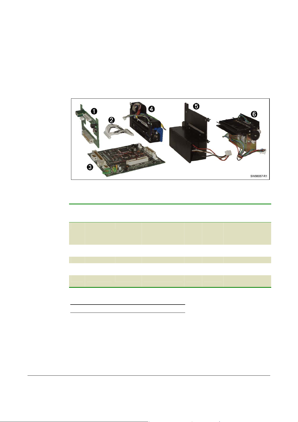
8.6 Replacement parts
Not all parts are replacement parts:
1. Screws, washers, nuts etc. are available in a common hardware store, and are thus
not replacement parts.
2. Parts that are considered as not being worn by normal printer use are not
replacement parts, for example the printer chassis.
Should you require any of these non-replacement parts, contact Swecoin for advice.
Figure 21. Replacement part modules
Item Ordering No. Designation Quantity Note
80 mm 112 mm 80 mm 112 mm
1 01122-080 01122-112 Print module 1 1 Complete with
printhead, connection
board, and printhead
cable
2 01125-000 01125-000 Printhead cable 1 1 Included in print
module
3 01119-901 01119-901 Control board 1 1
4 01121-080 01121-112 Cutter module 1 1 With motor, sensor,
cable, and connector
5 01120-080 01120-112 Presenter module 1 1 With motor, sensor,
cable, and connector
Table 17. Replacement parts, 80 mm printer
NOTE! See also Ordering numbers on page 77.
66 TTP 7000 Kiosk Printer – Technical Manual 0308
Page 67

8.7 Firmware
The firmware is stored in flash-PROM on the control board. A replacement control board
just contains a bootstrap program that is used to communicate through the parallel
interface to make it possible to load the firmware.
8.7.1 Loading
Fetch the firmware from the Swecoin web site http://www.swecoin.se. There you will also
find a loader program (Windows™ software) facilitating the loading of the firmware into
the printer.
The loader program contains a help file with detailed instructions on how to load the
firmware into the printer.
In non-Windows environments, use the following procedure to load the firmware:
1. Send ESC NUL (1BH 00H) to the printer.
2. Wait 0.5 seconds.
3. Send the firmware file to the printer.
4. Wait until the printer buzzes to confirm that the loading is complete (the presenter
motor runs for a second).
CAUTION! The loading and burning can take up to one minute. Do not abort before one
minute by turning OFF the power to the printer. Doing so may leave the printer in a state
where new firmware cannot be loaded.
0308 TTP 7000 Kiosk Printer – Technical Manual 67
Page 68

8.7.2 Firmware history
Functions and features are being added from time to time affecting the firmware in the
printer. The following table lists the changes of general interest.
Notice that the list may not contain the latest firmware versions. Please visit our web site
http://www.swecoin.se for current information.
FW version Change
1.00 First version released to customer, primary as Windows printer.
2.00 Added text mode support
2.10 Support for 112 mm paper width (Auto detect of width)
2.20 Support for retract and retain unit, and for new USB circuit on the PCB
2.30 New features
New command for printing logotypes added.
Added eject length calibration, parameter 47
Hex mode added. Activate by lifting head, paper at head and switch pressed at
power on.
Added Load Factory Defaults command (ESC & F)
Max Font height increased from 128 to 255 pixels.
Bug
Bugs removed from landscape mode printing on 112-mm printers.
Removed Serial number in the USB Descriptor. This is to avoid that each
TTP7000 unit connected to the USB get their own port and driver instead of
sharing the same driver with USB enumeration.
A bug that randomly caused the printer to freeze when erasing all fonts has
been removed. (Even loading new firmware did not help remove this state).
68 TTP 7000 Kiosk Printer – Technical Manual 0308
Page 69

2.35
2.37 Changed default value for N10 (pulse control), from 0 to 1.
New Features
Barcode commands added (EAN, UPC, I25, ISBN, Code39).
Bugs
Redesigned USB handling
Cutter, better sensing of cutter home sensor.
Fixed parameter handling.
Printer will now start in normal text mode (was bold).
Fixed so that paper reverse command (ESC 'j' n) no longer causes USB
chip to reset.
Auto-load timeout longer. Auto-load errors will now be reset at head lift.
Table 18. Firmware history
0308 TTP 7000 Kiosk Printer – Technical Manual 69
Page 70

9 SPECIFICATIONS
Specification subject to changes without notice.
9.1 Print data
Printer control Windows 95/98/ME and NT 4/2000/XP drivers.
Direct addressing through ESC sequences
Plug and Play Yes
Print method Direct thermal line printing
Resolution 8 dots/mm (203 dpi)
Feed pitch 1/8 mm (203 lpi)
Print speed Up to 75 mm/s
Print width
80-mm version 72 mm, 576 dots
112-mm version 104 mm, 832 dots
Interfaces Parallel IEEE-1284 and USB. Optional external RS-232 serial
interface adapter.
Serial interface settings Baud: 2 400, 4 800, 9 600, 19 200, 38 400,
57 600, 115 200 bits/s
Data bits: 7 or 8
Parity: None, Odd or Even
Stop bits: 1 (fixed)
Flow control: None, Xon / Xoff, or Hardware
Default settings: 9600 bits/s, 8 data bits ,no parity, 1 stop bit,
no flow control.
9.2 Text modes (non-Windows applications)
Orientation Horizontal (portrait mode) only
Number of possible fonts: 8
Font memory 256 kB
Font technology Bitmap fonts, non scaleable
Font format Swecoin proprietary
Standard fonts TTP Mono 9, Ariel 6p, 10p and 16p, Wingdings, Code 39
Text attributes Bold, underline, reverse print, multiple-width, multiple height.
Attributes can be combined on the same text line.
70 TTP 7000 Kiosk Printer – Technical Manual 0308
Page 71

9.3 Basic character set
The printer uses the ISO 8859-1 (ANSI) character set used in Windows. Other character
sets can be used, by creating and loading appropriate font files.
Characters 0 to 31 are control codes that cannot be changed, but 32 to 255 can be
custom designed.
The table below shows the characters stored in flash PROM on the printer control board.
Table 19. ISO 8859-1 (ANSI) character table
0308 TTP 7000 Kiosk Printer – Technical Manual 71
Page 72

Table 20. Symbol character table
72 TTP 7000 Kiosk Printer – Technical Manual 0308
Page 73

9.4 Paper handling
Paper width 80 mm or 112 mm depending on model
Receipt length 75–500 mm before partially ejecting receipt, no upper limit for
receipt length.
Cutting Guillotine cutter
Presenter operation Holds receipt until printed then cuts and presents the complete
receipt. Extremely long receipts can be partially ejected to limit
loop buildup.
Eject length after cut Programmable, full eject, or receipt held until the customer
removes it. Eject of uncollected receipts.
Receipt retraction Optional retract and retain function pulls pack uncollected
receipts and throws them in a wastebasket inside the kiosk.
Paper loading Automatic feed, cut, and eject when paper is detected.
Automatic "on-line" after successful paper load.
Sensors Optical sensors: Out of paper, paper left in presenter, paper
near end (optional) and weekend level sensor (optional).
Switch sensors: Cutter not in home position and printhead lifted.
0308 TTP 7000 Kiosk Printer – Technical Manual 73
Page 74

9.5 Printer dimensions
NOTE! – Additional space is required for paper roll and handling.
12.0 86.0
M4 (4x)
141.4
Roll holder
fastening
Roll
IEEE-1284C
holder
26.1
21.8
80.3 (112.3) Paper in
90.0 (122.0) Paper out
128.5 (160.5)
3.1 (4.1 with serial adapter)
Shutter
USB
Power
3.1
Bottom
76.0
85.5 (Paper out)
4
1.7
view
144.8
Cutter module
Delivery module
160.8 with optional serial adapter
104.0
12.5
Print module
Paper in 96.4
Card module
All measurements are in mm
Measurements in parenthesis are for TTP 7000/112
SW98050
Figure 22. Measurements drawing
9.6 Environmental conditions
Temperature Operating: 0 to +50 °C
Storage and transportation: –20 to +60 °C
Relative humidity Operating: 35 to 75%, non-condensing
Storage and transportation: 10 to 90%, non-condensing
74 TTP 7000 Kiosk Printer – Technical Manual 0308
Page 75

9.7 Miscellaneous
Weight 2.4 kg (80 mm), 2.85 kg (112 mm)
Typical throughput 1.5 s/receipt (length 75 mm, print, cut, and present)
Power requirements
80 mm version 24Vdc ±10%, idle 150 mA, average 2.5A, peak 8.5A
112 mm version 24Vdc ±10%, idle 150 mA, average 3.5A, peak 11A
Life expectancy Printhead: more than 50 km paper, more than100 million
pulse lines (typically)
Cutter: 500 000 cuts (typically)
Control board: 40 000 hours (typically)
1
MTBF
250 000 receipts (typically)
9.8 Paper specification
9.8.1 General
Paper supply Roll paper with heat sensitive coating (thermal paper)
Type of paper TF50KS-E2C, AF50KS-E, Mitsubishi TG7065, or equivalent is
recommended
Number of layers One
Paper weight 55—110 g/m²
Paper thickness 0.054—0.10 mm
Surface smoothness 450-s minimum according to Bekk TAPPI T 479
Reflection 80% minimum according to SCAN P3
Core Paper or plastic
Core inner diameter Minimum 25 mm
Paper end Must not be glued to the core
Paper width 80 +0/–0.3 mm, or 112 +0/–0.3 mm depending on model
Paper length Approx. 150 m (with 110-mm roll diameter and 65 g/m²)
Approx. 250 m (with 150-mm roll diameter and 65 g/m²)
Approx. 450 m (with 200-mm roll diameter and 65 g/m²)
9.8.2 Thermal coating
Thermal coating Outer side
Sensitivity Activated at approx. 68 °C saturated at approx. 75 °C.
Dynamic sensitivity 1.14 ±0.04 OD
1
MTBF figures does not include paper jam
0308 TTP 7000 Kiosk Printer – Technical Manual 75
Page 76

Top coating Standard, semi or UV (if applicable)
9.8.3 Perforation
Tear-off perforation Punching must be done from outer side (thermal coating side)
with a sharp perforation tool.
9.8.4 Preprinting
General To endure the heat developed during printing, the preprint must
meet the requirements applicable for preprinting on paper
intended for laser printing. OCR-blind ink must be used for
preprint on the inner side of the roll.
Ink used for preprinting on the thermal side must be non-
abrasive.
The ink must not smear while wound up on the supply roll or
during the printing process.
Print side One side or both sides.
9.8.5 Black mark size and position
See also Aligning preprint and thermal print on page 52.
Print side Inner side (opposite to thermal coating side)
Sensor position 25 mm before cutter, and 9.1 mm from left edge of ticket entry
when seen from the front of the printer (on the side of the blue
release arm).
Mark length range 3 to 18 mm, default 5 mm
Mark width Minimum 5 mm centered on the sensor position, recommended
width is 9 mm
Print density Standard wet offset mode is recommended for printing of the
black-marks. The full mark area must be printed. Screenprinting is not allowed. Measurement of print density must be
performed relative to the white paper background.
Using a MacBeth densitometer, the print density must be
greater than 1.3. Anti-gloss filter is not allowed. Using a Gretag
densitometer, the print density must be greater than 1.5. The
reflection from the black-mark must be less than 10%. The
reflection from the paper must exceed 80%.
Preprinting Preprinting in the zone passing over the black-mark sensor is
not recommended. If required, OCR blind type of ink must be
used, (outside the 700-1100 nm range).
Punched holes
Punching must be done from the thermally coated side. Distorted
print can be expected within a zone of approximately 2-mm around
the edges of the hole. The function must be tested.
76 TTP 7000 Kiosk Printer – Technical Manual 0308
Page 77

9.9 Ordering numbers
9.9.1 Printer assembly
Print Width: 80 mm 112 mm
Basic printer (no roll holder) 01100-080 01100-112
Evaluation kit containing one basic printer with 150 mm roll
01578-080 01578-112
holder and one each of the options marked with * in the
options list. (Only one evaluation kit/customer.)
9.9.2 Options
Print Width: 80 mm 112 mm
75 W Power supply unit (see figure 23) with 0.5 m PSU-to-
01776-000
printer cable
150 W Power supply unit (see figure 24) with 0.5 m PSU-to-
01035-014
printer cable, on/off switch, and fuse*
One sensor (paper-near-end) with 150 mm cable 01483-000
Two sensors (paper-near-end + weekend) with 200 mm cable 01579-000
IEEE-1284 cable, straight 1.8 m* 01366-000
IEEE-1284 cable, 90° angled 1.8 m 01366-090
USB cable, 1.8 m 01542-000
Serial adapter 01437-000
Serial cable, 1.8 m 01659-000
Paper roll, no preprint, for ∅110 mm roll holders, 65g/m²* 04767-000 04768-000
Paper roll, no preprint, for ∅150 mm roll holders, 65g/m² 01139-080 01139-112
Paper roll, no preprint, for ∅200 mm roll holders, 65g/m² 01543-080 01543-112
Technical manual* 01536-000
Printer driver package, Windows 9x and NT4/2000/XP* 01628-xxx
Retract and retain (Wastebasket) accessory1 (see figure 25) 01439-080* 01439-112
1
The retract and retain option must be ordered together with the printer and they are assembled together at delivery.
0308 TTP 7000 Kiosk Printer – Technical Manual 77
Page 78
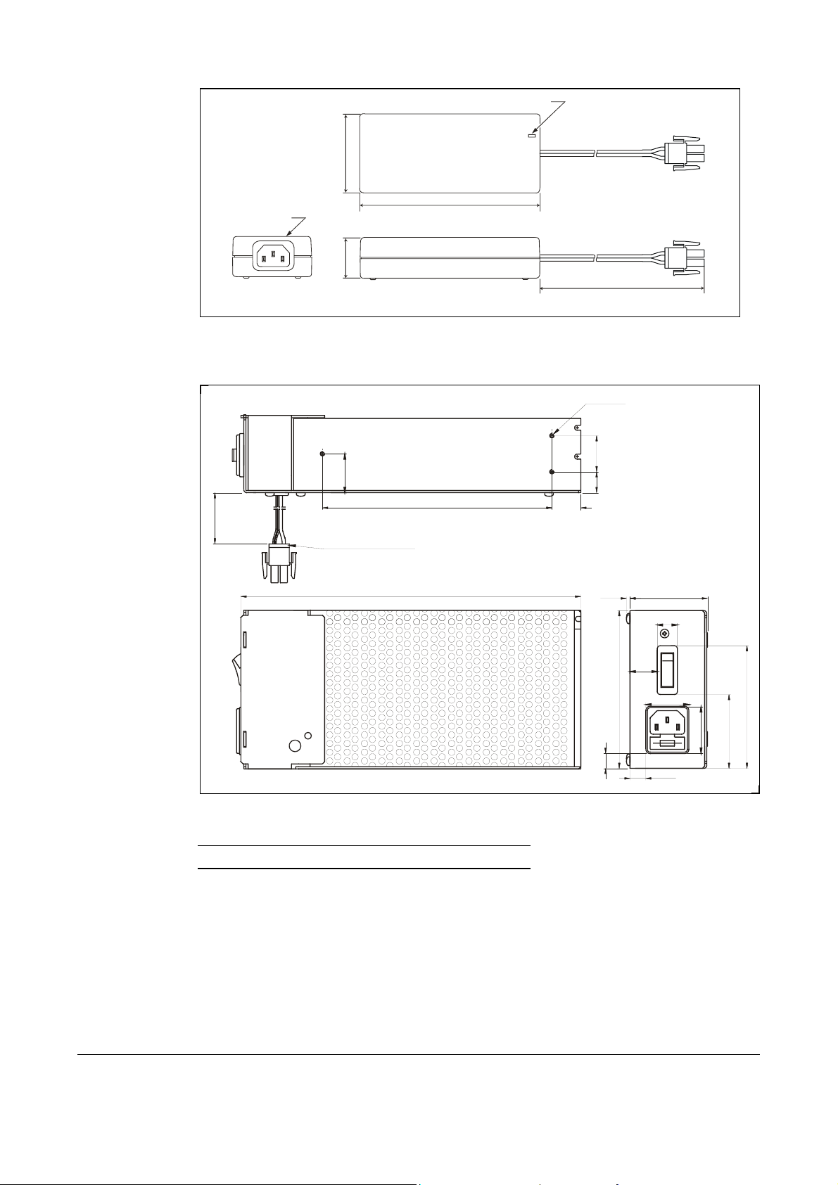
Power ON indicator
58
IEC320/C14
0
.
0
0
5
30
0
.
7
2
Cable 01370-000
132
Figure 23. 75W Power supply unit.
Bottom view
159.0
235.5
20.0
500mm
M3 (3x)
0
.
5
2
5
.
4
1
54.02.5
14.0
01776-000
19.0
0
.
0
1
1
5
.
0
1
30.0
11. 0
5
5
.
1
5
SW99013
5
.
5
8
.
2
3
Figure 24. 150W Power supply unit.
NOTE! – Mains cord is not included in the PSU's.
78 TTP 7000 Kiosk Printer – Technical Manual 0308
Page 79
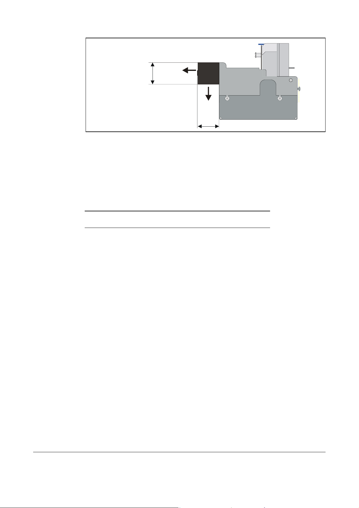
Receipt exit
on same height
36.5
as normal printer
Exit to
wastebasket
38
All measurements are in mm
Figure 25. Retract and retain option.
Choose between four modes in the default parameter setup:
1. Retract when new receipt is printed
2. Retract after a preset time
3. Eject to customer when new receipt is printed (wastebasket off)
4. Eject to customer when new receipt is printed, but retract if not collected within a preset time
No additional commands are required
NOTE! – Use paper rolls with an inner diameter of 40 mm or more
when using the "retract and retain" option.
SW00009
0308 TTP 7000 Kiosk Printer – Technical Manual 79
Page 80

9.9.3 Roll holders
Print Width: 80 mm 112 mm
Paper roll holder for up to 110 mm roll diameter.
With paper-near-end sensor.
140.5
Figure 26. Roll holder for paper rolls up to 110-mm
01148-080 01148-112
SENSOR
OUT
GND
+5V
All measurements are in mm
273.5
20.7
SW98045
Paper roll holder for up to 150 mm roll diameter.
With paper-near-end sensor.
182.0
Figure 27. Roll holder for paper rolls up to 150-mm
Print Width: 80 mm 112 mm
01123-080 01123-112
20.7
SENSOR
OUT
GND
+5V
All measurements are in mm
277.1
306.8
SW98046
80 TTP 7000 Kiosk Printer – Technical Manual 0308
Page 81

Print Width: 80 mm 112 mm
Paper roll holder for up to 200 mm roll diameter.
With paper-near-end and weekend sensors.
232.0
201.5
341.0
408.5
01149-080 01149-112
SENSOR
+5V
OUT
GND
SENS
+5V
OR
OUT
GND
25.7
324.3
23.8
M4 (2x)
72.4 (104.4)
All measurements are in mm
SW98048A
Figure 28. Roll holder for paper rolls up to 200-mm
0308 TTP 7000 Kiosk Printer – Technical Manual 81
Page 82

Print Width: 80 mm 112 mm
Paper roll holder for up to 250-mm roll mm roll placed below
printer. With paper-near-end and weekend sensors.
01754-080 01754-112
Figure 29. Roll holder for paper placed under printer. The roll can be fitted on two different levels, one for
150-mm roll, and one for 250-mm roll. This way, minimal space is required under the printer.
82 TTP 7000 Kiosk Printer – Technical Manual 0308
Page 83

Index
A
ACK...............................38
Aligning preprint and
thermal print ........52, 76
Ambient light....................9
API-calls ........................50
B
Barcode ...................29, 70
Baud ..............................70
Bi-directional port ..........56
Bit image graphics.........31
Black-mark ....................52
Blinking yellow indicator ..7
BMP-file.........................31
Burn time ............ See Print
contrast
Byte Mode .....................55
C
Centronics Mode ........ See
Compatibility Mode
Cleaning the printhead ..63
CloseHandle..................50
Coating..........................76
Compatibility Mode........55
Connecting to the
computer ...............9, 10
Connector, parallel ..........9
Connector, USB ............10
Contrast adjustment ......33
Control board...................6
ordering No................66
replacement...............65
Core diameter................75
CreateFile......................50
Current consumption .....32
Cutter module
ordering No................66
replacement...............65
Cutter not in home position
..................................38
Cutting ...........................73
D
Data bits ........................70
Data, send graphics ......31
Decimal codes...............19
Default settings..............47
Serial interface ..........61
Disassembly ..................64
Dismantling....................64
Drawing
printer mechanism.....74
roll holder 110 mm.....80
roll holder 150 mm.....80
roll holder 200 mm.....81
shelf.............................8
Driver installation.......6, 12
E
Earth currents..................9
ECP Mode..................... 55
Eject length after cut .....73
Enclosure ........................8
Environmental conditions
..................................74
EPP Mode ..................... 55
Error
codes ........................46
indication..................... 7
ESD........................... 9, 64
Evaluation kit.................77
F
Fault finding...................62
Feed paper...................... 7
FF button................... 7, 17
Firmware
history .......................68
loading ......................67
Flashing yellow indicator . 7
Flow control................... 70
G
Graphics data................ 31
Green indicator................7
Ground ............. See Earth
H
Heat, adjustment ........... 33
Hex codes .....................19
Humidity ........................74
I
IEEE-1284 6, 9, 10, 11, 55,
70
cable .........................77
Image data .................... 31
Indicators.........................7
Installation....................... 8
paper roll ...................14
paper-near-end sensor
..............................12
printer driver .......... 6, 12
Interface ........................70
Interface cable.................9
K
Kiosk ...............................8
L
Light ................................9
Loading firmware........... 67
M
Maintenance.................. 62
Minimum receipt length . 34
Mounting shelf.................8
MTBF ............................75
N
NAK .............................. 38
Negotiation.............. 59, 60
Nibble Mode............ 55, 59
Noise, excessive........... 32
O
Operation ...................... 14
Orientation ....................70
Out of paper.................. 73
P
Paper
dimensions................ 75
end............................ 73
feed............................. 7
left in presenter ... 38, 73
length ........................ 75
loading ...................... 73
near end.............. 12, 73
near end enquiry....... 39
near end sensor ........ 77
specification .............. 75
supply ....................... 75
surface smoothness.. 75
thickness................... 75
type ........................... 75
weight ....................... 75
width ................... 73, 75
Paper roll
holder............ 80, 81, 82
installation................. 14
ordering number........ 77
specifications ............ 75
Paper-feed error............ 38
Paper-lowSee Paper-near-
end
Parallel
connector .................... 9
port........................ 9, 50
Parity............................. 70
Perforation ....................76
Pin assignment
Parallel port............... 55
Serial port ................. 61
USB port ...................61
Pitch.............................. 70
Plug and Play...... 6, 41, 70
Power connection ......... 11
Power requirements...... 75
Power supply ................11
Preprint ......................... 76
Presenter module
ordering No. .............. 66
replacement .............. 65
Presenter principle ........ 73
Print
contrast ..................... 33
method...................... 70
quality ....................... 32
side ........................... 76
0308 TTP 7000 Kiosk Printer – Technical Manual 83
Page 84

speed.....................6, 70
width..........................70
Print module
ordering No................66
replacement...............64
Printer
control........................70
driver ...............6, 12, 50
opening......................16
operable ....................38
out of paper ...............38
Printhead
cleaning .....................63
lifted.....................38, 73
Printout, self-test ...........17
Product presentation .......6
Programming.................19
Protective earth ...............9
Punching .......................76
R
ReadFile ........................50
Receipt length .........34, 73
Red indicator ...................7
Reflection, paper ...........75
Relative humidity ...........74
Replacement parts ........66
Request device ID .........59
Request ECP Mode.......59
Request EPP Mode.......59
Reset printer...... 19, 36, 38
Resolution .....................70
Retract and retain... 47, 49,
68, 73, 77
Reverse direction
communication ..........56
RS-232............................ 6
RS-232 adapter............. 61
S
Self-service kiosk ............ 8
Self-test printout ...... 11, 17
Sensitivity ...................... 75
Sensor, paper-near-end 12
Sensors......................... 73
Serial interface ................6
SetCommTimeouts .......50
Shelf................................ 8
Smoothness, paper ....... 75
Spare parts................. See
Replacement parts
Status
code ..........................38
indicator ......................7
Stop bits ........................70
Summary of control codes
& escape sequences . 19
T
Tear-off perforation .......76
Temperature ................. 74
Temperature error......... 38
Terminal faults .............. 38
Test printout............ 11, 17
Thermal coating ............ 75
Throughput ................... 75
TOF mark. See Black-mark
Tools ............................. 64
U
USB .............................. 61
connector .................. 10
port............................ 10
V,W
Wastebasket option ....See
Retract and retain
Weight........................... 75
Win32............................ 50
Windows .. 2, 6, 12, 41, 50,
67
WriteFile........................ 50
X
Xon / Xoff ...................... 70
Y
Yellow indicator............... 7
84 TTP 7000 Kiosk Printer – Technical Manual 0308
 Loading...