

P1003640-004 Rev. A
Zebra® TTP 2100
Kiosk Ticket Printer
Technical Manual

© 2012 ZIH Corp. The copyrights in this manual and the software and/or firmware in the printer described
therein are owned by ZIH Corp. and Zebra’s licensors. Unauthorized reproduction of this manual or the software
and/or firmware in the printer may result in imprisonment of up to one year and fines of up to $10,000
(17 U.S.C.506). Copyright violators may be subject to civil liability.
This product may contain ZPL®, ZPL II®, and ZebraLink™ programs; Element Energy Equalizer™ Circuit; E3™;
and Monotype Imaging fonts. Software © ZIH Corp. All rights reserved worldwide.
ZebraLink, Element Energy Equalizer, E3 and all product names and numbers are trademarks, and Zebra, the Zebra
head graphic, ZPL and ZPL II are registered trademarks of ZIH Corp. All rights reserved worldwide.
All other brand names, product names, or trademarks belong to their respective holders. For additional trademark
information, please see “Trademarks” on the product CD.
Proprietary Statement This manual contains proprietary information of Zebra Technologies Corporation and its
subsidiaries (“Zebra Technologies”). It is intended solely for the information and use of parties operating and
maintaining the equipment described herein. Such proprietary information may not be used, reproduced, or disclosed
to any other parties for any other purpose without the express, written permission of Zebra Technologies Corporation.
Product Improvements Continuous improvement of products is a policy of Zebra Technologies Corporation.
All specifications and designs are subject to change without notice.
Liability Disclaimer Zebra Technologies Corporation takes steps to ensure that its published Engineering
specifications and manuals are correct; however, errors do occur. Zebra Technologies Corporation reserves the right
to correct any such errors and disclaims liability resulting therefrom.
Limitation of Liability In no event shall Zebra Technologies Corporation or anyone else involved in the creation,
production, or delivery of the accompanying product (including hardware and software) be liable for any damages
whatsoever (including, without limitation, consequential damages including loss of business profits, business
interruption, or loss of business information) arising out of the use of, the results of use of, or inability to use such
product, even if Zebra Technologies Corporation has been advised of the possibility of such damages. Some
jurisdictions do not allow the exclusion or limitation of incidental or consequential damages, so the above limitation
or exclusion may not apply to you.

Contents
1 • Introduction .................................................... 7
About this Manual ....................................................... 7
2 • Product Presentation ............................................ 9
TTP 2100 Series ........................................................ 9
Presenter ............................................................. 12
Eject Mode ......................................................... 12
Hold Mode ......................................................... 12
Controls .............................................................. 13
Feed Button ....................................................... 13
Power Indicator ..................................................... 14
Status Indicator ..................................................... 14
3 • Installation .................................................... 15
Installing a Paper Guide .................................................. 15
Top of Form (TOF) Sensor ................................................ 19
Selecting Fork (Transmissive) or Reflex (Black Mark) TOF Sensor .............. 19
Calibrating the TOF Sensor ............................................ 20
Positioning the TOF Sensor ............................................ 20
Installation Considerations ................................................ 21
Orientation ......................................................... 22
Quick-Fit Hubs ...................................................... 23
Design Your Own Mounting ............................................ 24
Electrostatic Discharges and Earth Currents ............................... 25
Ambient Light ....................................................... 25
Installing a Paper-low Sensor (Optional) ..................................... 26
Connecting to the Computer .............................................. 27
TTP 2110 .......................................................... 28
TTP 2130 .......................................................... 28
09/18/2014 TTP 2100™ Technical Manual P1003640-004

Contents
4
Connecting the Power ................................................... 29
Making a Self-Test Printout ............................................... 31
Customizing the Self-Test Printout ...................................... 33
Installing a Printer Driver ................................................. 33
4 • Operation ..................................................... 35
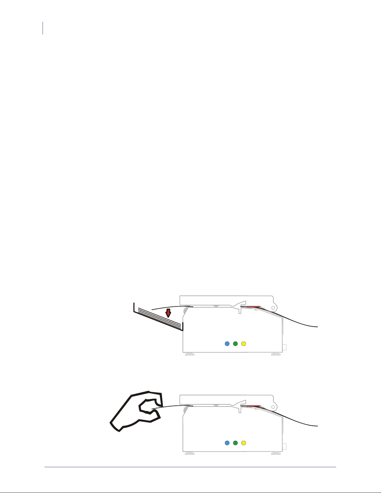
Loading Fanfold Ticket Stock .............................................. 36
Installing a Paper Roll ................................................... 37
Clearing Paper Jams .................................................... 39
5 • Programming .................................................. 41
Programming Overview .................................................. 42
How the Commands are Described ......................................... 43
Summary of Control Codes and Escape Sequences ........................... 45
Software Command Syntax ............................................... 48
Black Mark (Top-of-Form) Commands .................................... 48
Text Commands ..................................................... 49
Barcode Commands ................................................. 56
Graphics Commands ................................................. 62
Print Commands .................................................... 65
Cut and Present Commands ........................................... 67
System Related Commands ........................................... 70
Status Reporting Commands .......................................... 74
Font Loading .......................................................... 85
File Format ......................................................... 85
Character Bitmap Data ............................................... 86
Logotypes ............................................................ 87
Loading ........................................................... 87
File Format ......................................................... 87
Printing ............................................................ 88
Erasing ............................................................ 88
Status Reporting ....................................................... 89
6 • Default Parameter Settings ....................................... 91
Parameter Settings ..................................................... 91
How the Parameters are Described ......................................... 92
Default Value ....................................................... 92
Examples .......................................................... 92
Summary of Parameter Settings ........................................... 92
Serial Interface Set-up ................................................... 94
Print Setup ............................................................ 95
Fixed Document Mode ............................................... 100
P1003640-004 TTP 2100™ Technical Manual 09/18/2014

Contents
7 • Page Setup ................................................... 109
Printable Area ........................................................ 109
Aligning Preprint and Thermal Print ........................................ 110
Simple Calibration Process ........................................... 112
FF (Form Feed) ....................................................... 113
Black Mark Sensing from within Windows ................................... 113
8 • Interface ..................................................... 115
Printer Interface ....................................................... 115
Serial: TTP 2110 ...................................................... 115
Setup Options ..................................................... 116
USB: TTP 2130 ....................................................... 117
9 • Maintenance ................................................. 119
Fault Finding / Troubleshooting ........................................... 119
Cleaning the Printhead ................................................. 121
Cleaning the Presenter and Platen Rollers .................................. 121
Firmware ............................................................ 121
Loading .......................................................... 122
Firmware Identification ............................................... 126
5
10 • Specifications ...............................................127
Ticket Specifications ................................................... 128
TOF Detection ........................................................ 129
Features .......................................................... 129
Print Module .......................................................... 129
Ticket Separation ...................................................... 129
Presenter ............................................................ 130
Electronics ........................................................... 130
Firmware ............................................................ 130
Text Mode ............................................................ 131
Miscellaneous ........................................................ 131
Basic Character Set .................................................... 131
Part Number List ...................................................... 133
Printers .......................................................... 133
Accessories ....................................................... 133
Dimensions .......................................................... 134
Printer ........................................................... 134
Media Holder ...................................................... 135
Power Supply ...................................................... 136
Output Tray ........................................................ 136
09/18/2014 TTP 2100™ Technical Manual P1003640-004

Contents
6
A•₼⦌ 5R+6 㧟㠨⭿㢝
(China RoHS Material Declaration) .................. 137
Index ........................................................... 139
P1003640-004 TTP 2100™ Technical Manual 09/18/2014

1
Introduction
Contents
About this Manual ....................................................... 7
Contacts ............................................................... 8
About this Manual
This manual is updated from time to time when printer functions and features are added or
amended. You can find the latest edition on our website at
functions not found in this manual edition, please contact
the Zebra partner from which you purchased the printer.
www.zebra.com. If you require
Technical Support for your region or
09/18/2014 TTP 2100™ Technical Manual P1003640-004

Introduction
8
About this Manual
P1003640-004 TTP 2100™ Technical Manual 09/18/2014

2
Product Presentation
Contents
TTP 2100 Series ........................................................ 9
Presenter ............................................................. 12
Controls .............................................................. 13
TTP 2100 Series
The TTP 2100 series of ticket printers are available both for Kiosk integration and Desktop
use. These printers are Common Use Self-Service (CUSS) capable.
These ticket printers print on most ticket media from 50 mm to 82.5 mm wide using direct
thermal printing. The ticket media can be up to 0.25 mm thick, fanfold, roll, or single cut
handfed.
09/18/2014 TTP 2100™ Technical Manual P1003640-004

Product Presentation
10
TTP 2100 Series
The printers have an integrated guillotine cutter, straight presenter, and control board. The
print speed is up to 150 mm/s and the eject speed 300 mm/s to ensure high throughput.
The cut can be synchronized with:
• Gaps between tickets, or punched holes
• Black marks on the non thermal side of the ticket stock
• Ticket corner radius
• Label gaps (for adhesive labels on backing/liner)
You can also print fixed-length or variable-length tickets without synchronization. The
presenter can be set to eject the ticket into a tray or hold it by the back edge until the customer
takes it. The top can easily be opened to give the operator access to the paper path and
printhead for maintenance purposes.
P1003640-004 TTP 2100™ Technical Manual 09/18/2014

Figure 1 • Principle of Operation
Product Presentation
TTP 2100 Series
9
11
5
4
3
2
1
Control panel on both sides
1
Cutter
2
Tickets fall (into tray)
3
Ticket sensor (taken/fallen)
4
Straight presenter
5
Ticket load sensor
6
Printhead
7
Upper media sensor (IR light source), adjustable sideways
8
Top release lever
9
Paper entry
10
Lower media sensor (IR light receiver), adjustable sideways
11
Control board
12
6
7
8
10
11
12
The upper media sensor is an IR light source that illuminates the media. The lower media
sensor is an IR light receiver. These sensors must work together to sense media gaps or out-ofmedia conditions.
The printer is available with two different control boards; the TTP 2110 with serial interface
and the TTP 2130 with USB interface.
A printer driver for Microsoft Windows™ is available, and the TTP 2130 interface is
compatible with the Plug and Play standard.
09/18/2014 TTP 2100™ Technical Manual P1003640-004
Product Presentation
12
Presenter
Presenter
Eject Mode
Hold Mode
The KPL control command language makes it easy to print directly from the ticket software
without using a driver. This is especially useful for the serial interface version with its limited
data transfer rate.
The TTP 2100 does not loop the media. The presenter carries the media through the printer for
presentation to the user.
The ticket is ejected after being cut. The printer is designed so that the ticket always drops
down. A sensor is located at the exit of the presenter to ensure that the printer can verify that
the ticket drops down. To enable this functionality, in the Properties dialog, click the Device
Settings tab, and under Presenter Settings set the Clear presenter value to Ye s .
When presented, only the very end of the printout is held by the printer so the customer can
easily take the printout no matter how long or short it is. If a customer is printing more than
one ticket, the printer can detect when the first is taken and automatically print the next and
hold that ticket until taken, continuing this process until all tickets have been printed.
Figure 2 • The Presenter
Print and drop
Print and take
P1003640-004 TTP 2100™ Technical Manual 09/18/2014
Controls
Cover lock
Feed Button
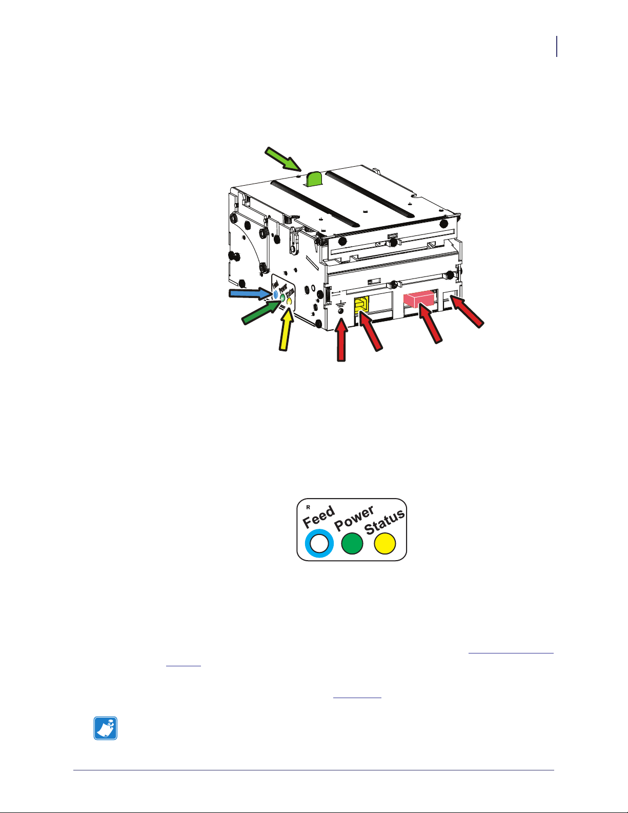
Figure 3 • Rear View
Product Presentation
Controls
13
The buttons and indicators are duplicated on both sides of the printer so that they are easily
accessible regardless of how the printer is installed.
Feed Button
The Blue Feed button has several functions:
• Press and release will feed, cut, and present a complete page.
• Any data in the print buffer will be printed.
If the buffer is empty the page will be blank.
In black mark mode, the page will be synchronized with the black mark.
Power Indicator
Status Indicator
Earth
Screw
Interface
Connector
Paper low
Connector
Power
Connector
• Press and hold Feed for three seconds to print a self-test printout (See
Making a Self-Test
Printout).
• With no paper in the printer, hold the Feed button pressed while closing the printhead to
enter TOF mark calibration mode (see
Note • If the printer has firmware version 3.82 or lower, press and hold the Feed button
Print Setup).
while turning on the printer to print a self-test printout.
09/18/2014 TTP 2100™ Technical Manual P1003640-004

Product Presentation
14
Controls
Power Indicator
Status Indicator
● When the green power indicator is illuminated, a 24V supply is connected to the printer.
● The status indicator has several functions:
• ON constantly — the printer is operational
• Flash, flash, pause, flash, flash — is the warning-code for paper low.
The warning-code is reset automatically when the condition causing it is removed.
This behavior is disabled by default but can be enabled by setting parameter 52
(Warning Level) to 1.
• Flashes rapidly — indicates error. Hold down the Feed button and the number of flashes
will reflect the status-code.
Table 1 • Status Indicator Flash Codes
Number of
Flashes
1 Presenter jam, paper cannot be ejected
2 Cutter cannot return to home position
3 Out of paper
4 Printhead lifted
5 Paper did not reach presenter sensor in time
6 Temp error, printhead is above 60
7 Paper jam during present
10 TOF mark not found (on media load)
11 TOF mark calibration error
Fast flashes Checksum error at firmware loading
Steady light Wrong firmware type
Constantly off Waiting for paper in TOF mark calibration mode
Status codes are reset:
Description
°C
• When the conditions causing them are removed.
• When the printer is power cycled (turned off and then on).
• For all paper jam conditions, after the jam is cleared, lifting and lowering the printhead.
P1003640-004 TTP 2100™ Technical Manual 09/18/2014

3
Installation
Contents
Installing a Paper Guide .................................................. 15
Top of Form (TOF) Sensor ................................................ 19
Installation Considerations ................................................ 21
Installing a Paper-low Sensor (Optional) ..................................... 26
Connecting to the Computer .............................................. 27
Connecting the Power ................................................... 29
Making a Self-Test Printout ............................................... 31
Installing a Printer Driver ................................................. 33
Installing a Paper Guide
Caution • Before proceeding, always disconnect the printer from power to avoid the
guide installation short circuiting the electronics in the printer. If the printer is installed in
a Kiosk, then all Kiosk power should be turned off to prevent the screw or media guide
bracket from accidentally falling into powered up Kiosk components (e.g., the screw or
bracket may fall and bounce into the Kiosk components mounted adjacent to or
mounted below the printer).
TTP 2100 printers are delivered without the paper guide fitted. TTP 2100 paper guides are
available in widths ranging from 51 mm to 82.5 mm. A dual paper guide is available with a
54 mm and 82.5 mm paper path.
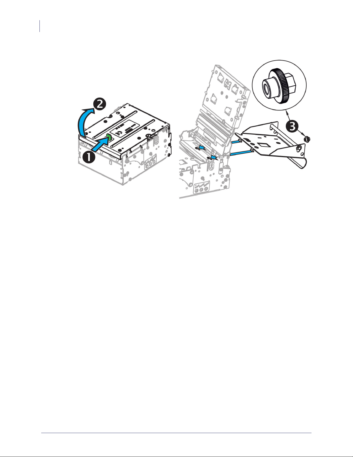
1. Push the green printhead open lever backwards.
2. Lift up the printhead. See Clearing Paper Jams.
3. Insert the T-shaped tabs of the paper guide into the “T”-holes, press the rear of the guide
down, and using your fingers or a 5 mm wrench tighten the knurled nut.
4. Close the printhead.
09/18/2014 TTP 2100™ Technical Manual P1003640-004
Installation
16
Installing a Paper Guide
Figure 4 • Fitting the TTP 2100 Paper Guide
When a guide is fitted, make an auto calibration (see Calibrating the TOF Sensor
on page 20) with the ticket media that you are going to use in the printer. Most ticket
media auto calibrate perfectly, and the printer is ready to use.
P1003640-004 TTP 2100™ Technical Manual 09/18/2014
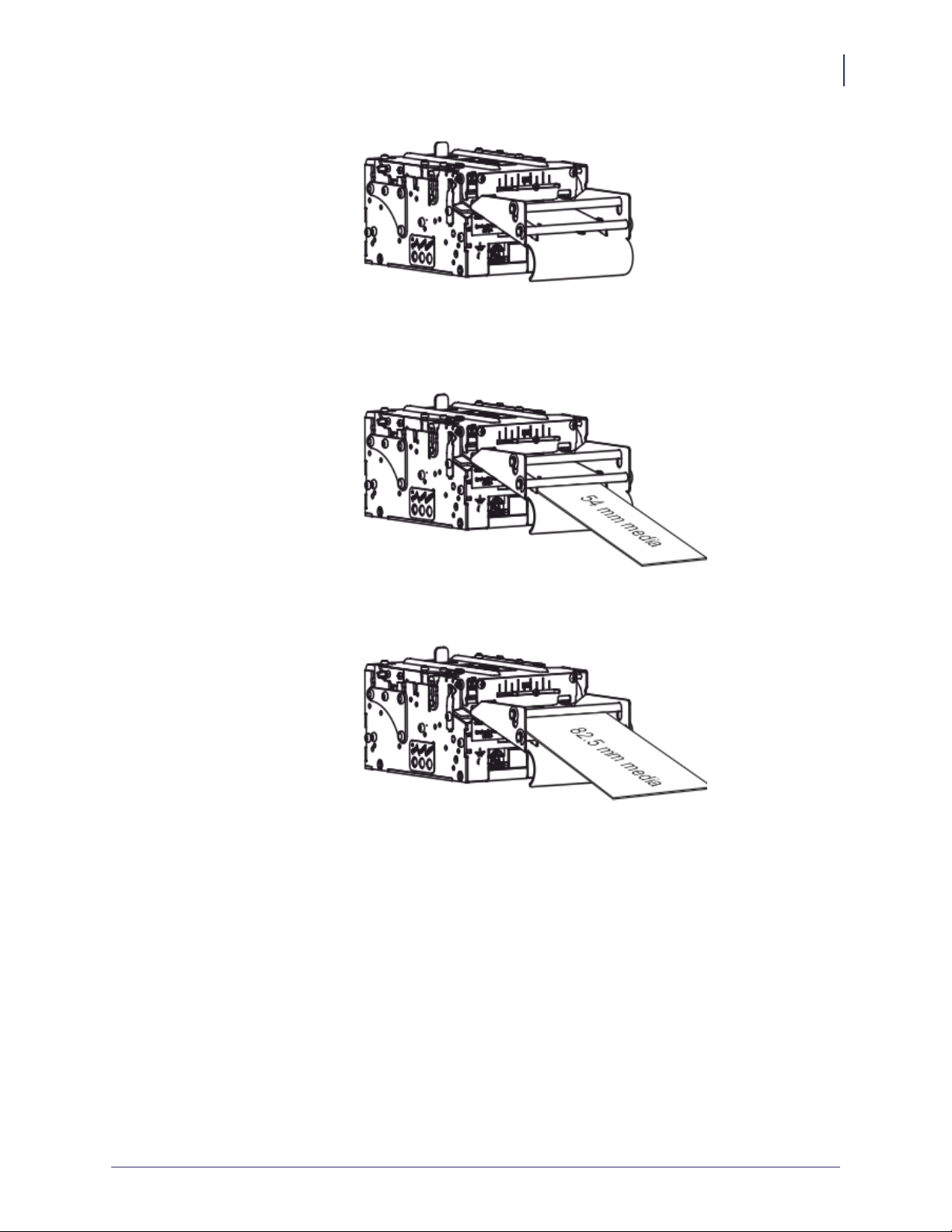
Figure 5 • TTP 2100 Dual Paper Guide
Installation
Installing a Paper Guide
17
If you use the TTP 2100 Dual Paper Guide 01990-400 on your printer, you must calibrate
twice (once in the wide paper path and once in the narrow paper path). The printer chooses
the appropriate set of parameters based on which paper path contains ticket stock.
If auto calibration fails on your media, set up paper width parameter n48, and sensor
selected parameter n63 to reflect your media. Then redo the auto calibration.
09/18/2014 TTP 2100™ Technical Manual P1003640-004
Installation
18
Installing a Paper Guide
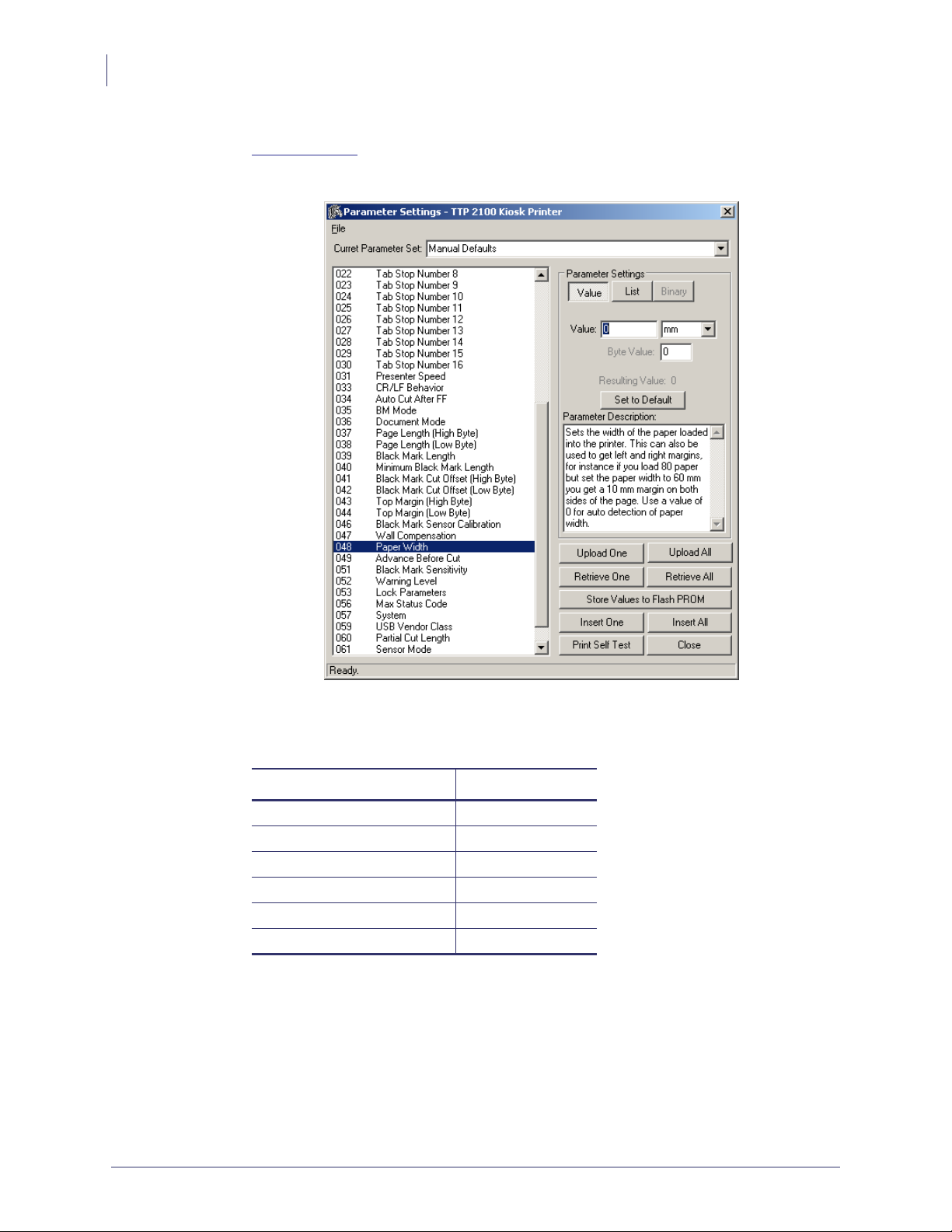
5. Start the utility program Zebra Toolbox. This application is available from
www.zebra.com.
6. On the Tools menu, click Parameter Settings.
7. Select 048 Paper Width, click Value, and enter the value in millimeters of the desired
print width.
Paper Width Setting
82.5 mm n48=80
80 mm n48=72
76 mm n48=70
60 mm n48=54
54 mm n48=50
51 mm n48=46
8. Click Upload One.
P1003640-004 TTP 2100™ Technical Manual 09/18/2014

Installation
Top of Form (TOF) Sensor
9. Select 063 BM Sensor and enter the desired value. Recommended values are:
Value When Used
0 Auto selects between 1, 2, 3, and 4 based on width of media loaded
1 (edge sensor) for ATB tickets without hole in the perforation
2 (center sensor) for ISO tickets, most other ticket types, and adhesive labels
3 17.5 mm from center sensor
4 12.5 mm from center sensor (for baggage tags according to IATA 740)
10. Click Upload One.
11. Click Store Values to Flash PROM.
12. Wait for the printer to buzz as a confirmation that the new value is stored.
Note • It is recommended that you run the auto calibration routine when the printer is
taken out of the box and whenever you change the media. Running auto calibration after
a head open event is recommended but is only necessary to insure proper first ticket
registration.
19
Top of Form (TOF) Sensor
The TTP 2100 has a flexible top of form detection system. When delivered the printer is
configured with fork (transmissive) sensor to detect holes/gaps between tickets. The
holes/gaps should be in the paper center, 12.5 mm to the right of the center (Bag tags
according to IATA resolution 740), 17.5 mm to the right of the center, or at the edge of
82.5 mm wide tickets (Boarding cards).
If the Top Of Form (TOF) mark is at a suitable position, an auto calibration routine configures
everything for you.
You can force the printer to use a specific sensor. If you switch to reflex sensor for black mark
detection by setting up the parameters in the printer to enable the use of non-standard sensor
positions, you can physically move the sensor to other positions.
Selecting Fork (Transmissive) or Reflex (Black Mark) TOF Sensor
The TTP 2100 can use a fork (transmissive) sensor that looks for holes between tickets, or a
reflex (black mark) sensor that looks for black marks on the back of the ticket stock. Sensor
mode is selected with parameter n61, see
Summary of Parameter Settings.
09/18/2014 TTP 2100™ Technical Manual P1003640-004

Installation
20
Top of Form (TOF) Sensor
Calibrating the TOF Sensor
1. Open the printhead.
2. Remove the ticket stock.
3. Press and hold the Feed button, and then close the printhead (keeping the button pressed
the entire time).
4. Release the button.
The Status LED should be off.
5. Load ticket stock (slide it into the paper guide and let the printer auto load the paper).
Note • To ensure good calibration conditions, lightly press the ticket stock towards the
bottom of the input guide during calibration.
The printer will forward the paper until it finds two TOF marks and then stop and save all
TOF-mark parameters.
6. Open the printhead and remove the ticket stock.
7. Close the printhead and feed the tickets in through the paper guide again.
The printer is ready for use.
Repeat this procedure if the calibration fails or if the printer is used with tickets that differ
from the original specification.
Note • If you use the Dual guide 01990-400 on your printer, you must calibrate twice (once
in the wide paper path and once in the narrow). The printer will choose the appropriate set of
parameters based on which paper path contains ticket stock.
Positioning the TOF Sensor
Note • Moving the sensor and IR source require customized paper guides with holes for the
new sensor position. Please contact Zebra Development Services (CAG) if your application
requires a non-standard sensor position.
The sensor board containing the lower media sensor sits on a bracket that can slide left and
right in a groove (see Figure 32, Sensor Positioning, on page 110). This bracket is located
below the ticket entry. The IR light source (upper media sensor) sits on a similar bracket above
the ticket entry. When delivered, the bracket is positioned to the far right. In this position
Sensor 1 is at the right side ready to detect the corner radius of Boarding cards, Sensor 2 is at
the center of the page, and Sensor 4 is 12.5 mm to the right of the center at the position
determined for baggage tags in IATA resolution 740. To configure the printer for other papers
that do not fall into any of the three categories, complete the following steps:
1. Loosen the screw holding the sensor 1 ½ turns.
2. Press the screw in with the screwdriver and carefully slide it to the new position making
sure the cables to the sensor do not obstruct the movement.
P1003640-004 TTP 2100™ Technical Manual 09/18/2014

3. Tighten the screw.
4. Move the IR light source (upper media sensor) to the same position, directly above the
sensor.
Installation Considerations
The TTP 2100 Kiosk printer is for embedded applications and should be installed in an
enclosure such as a self-service Kiosk.
Installation
Installation Considerations
a3
21
Upper sensor
adjuster
Lower sensor
adjuster
Caution • NEVER use screws that go into the printer more than 4 mm! Longer screws will
destroy the electronics inside.
The TTP 2100 Desktop printer is a stand alone printer in a housing. The housings can be
stacked so two or more printers can reside on top of each other to save space.
09/18/2014 TTP 2100™ Technical Manual P1003640-004

Installation
22
Installation Considerations
Orientation
The TTP 2100 printer can be installed horizontally or vertically. Horizontal is the most
common use but vertical with the ticket presenting upwards can be used if you want the ticket
to come up from the desk surface. Vertical with the ticket presented downwards can be used if
you want to stack many tickets before picking them up.
Figure 6 • Printer Installation Orientation Options
P1003640-004 TTP 2100™ Technical Manual 09/18/2014

Quick-Fit Hubs
The printers attach to the Kiosk in two ways:
• Using two screws
• Using slides with leaf spring retainers and the quick-fit hubs
Ticket exit
Figure7•Front, Bottom View
Push down
Installation
Installation Considerations
Quick-fit hubs
23
Optional
quick-fit
hubs
Keyholes
Lock spring
Push
forward
Fitted
09/18/2014 TTP 2100™ Technical Manual P1003640-004

Installation
24
Installation Considerations
Design Your Own Mounting
The illustration below gives an example of a printer-mounting shelf. See Dimensions, and the
3D solid models and outline drawings for CAD that are available on
www.zebra.com.
Figure 8 • Example of a Simple Shelf for Fastening a Standard Printer Using
Quick-Fit Hubs and a Leaf Spring Retainer (Order No. 01473-000)
m
m
5
.
1
Leaf spring
01473-000
Inner corner of bend
134 mm
110 m m
90.8 m m
10 mm
∅12 mm
Center
10 mm
Min. 100 mm
∅6.5 mm
+ 10 mm
Paper width
8 mm
44 mm
10 mm
Add material for corner radius
Additional space is required for paper loading and paper jam removal, Consider mounting the
printer on a movable platform so that the printer can be maintained outside the printer
enclosure.
We recommend that you make the output slot 97 mm wide. This way you will be able to use
all paper widths that the TTP 2100 series of printers can handle.
P1003640-004 TTP 2100™ Technical Manual 09/18/2014

Caution • NEVER use screws that go into the printer more than 4 mm! This will destroy the
electronics inside.
Electrostatic Discharges and Earth Currents
Preventing ESD and earth currents from affecting the printer operation requires proper
connection of the printer chassis to protective earth through a mounting platform or through a
separate earth conductor. A threaded hole for an M4 earth screw is provided on the back of the
printer. Use an M4 x 10 screw and two lock washers when fastening the ground cable.
Figure 9 • Location of Earth Grounding Screw
Installation
Installation Considerations
25
Earth
Screw
Note • An optional antistatic brush can be fitted to the front of the printer if required.
Ambient Light
There is an optical sensor at the paper exit at the front of the printer.
To ensure proper printer operation, design the Kiosk so that it prevents direct sunlight or light
from indoor lamps from reaching the sensor through the paper exit.
09/18/2014 TTP 2100™ Technical Manual P1003640-004
Installation
26
Installing a Paper-low Sensor (Optional)
Installing a Paper-low Sensor (Optional)
A paper-low sensor alerts the system that the media stock level is running low. The paper-low
sensor works with paper rolls and fanfold media.The purpose of this sensor is to get an early
alert so that you can replace the ticket stock in time in remotely located Kiosks.
The paper-low sensor operates by reflecting a light against the side of a media roll to detect it.
When the media is low, no light is reflected.
The printer automatically reads the paper-low sensor to check media status every time a
printout is cut. After three successive readings show that no paper is present at the sensor, the
status is set to paper low which alerts the system that the media needs to be replaced. Three
successive readings are required to prevent false paper low readings if the side of the media
roll is not clean. When a new roll of media is installed, the printer reads the sensor when the
printout is cut and the paper-low status is changed to paper present or paper not low.
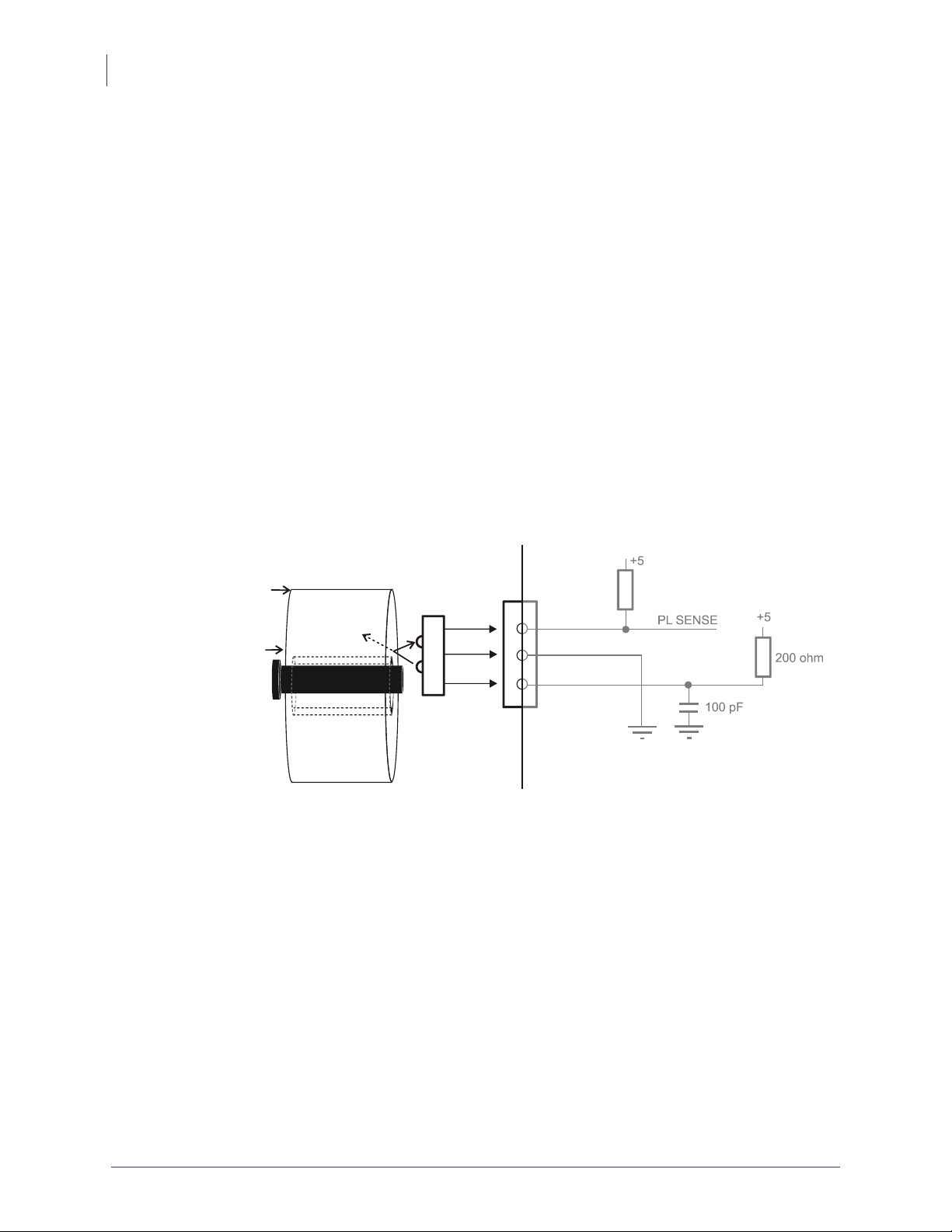
Roll holders supplied by Zebra can be equipped with paper-low sensors. Attach the sensor and
connect the cable to the paper low connector at the back of the printer.
Paper roll
New
Near
end
Figure 10 • Paper-low Sensor Connection
Roll holder shaft
Paper-low
sensor
J10
+5
3
2
1
PL SENSE
Gray = Connection
inside printe r
+5
200 ohm
100 pF
SW97081F
P1003640-004 TTP 2100™ Technical Manual 09/18/2014
Installation
Connecting to the Computer
27
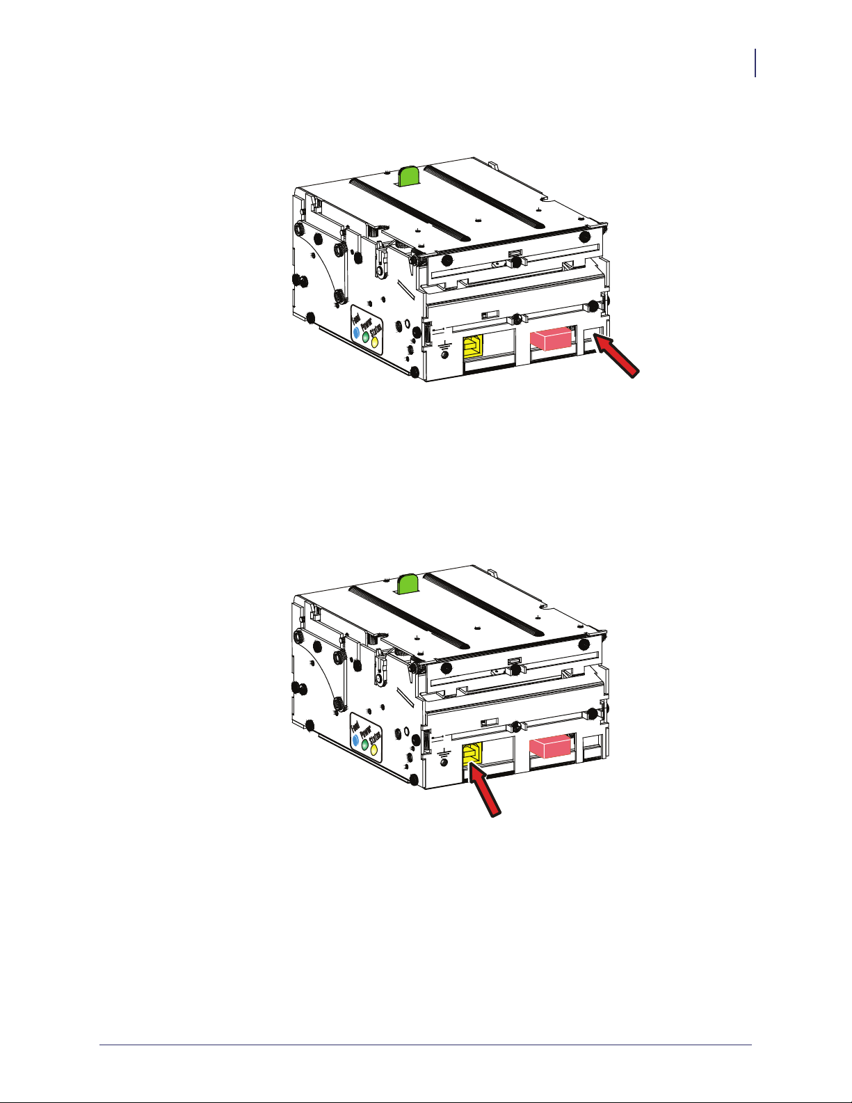
Figure 11 • Location of Paper-low Connector
Paper Low
Connector
Connecting to the Computer
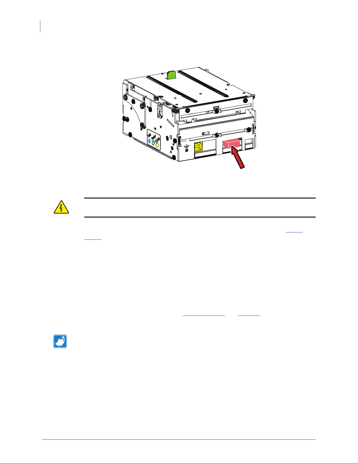
Figure 12 • Location of Interface Connector
Interface
Connector
09/18/2014 TTP 2100™ Technical Manual P1003640-004
Installation
28
Connecting to the Computer
TTP 2110
Connect a Zebra serial cable (part No. 10825-000) between the printer and the computer to be
used. We strongly recommend using the Zebra cable because many incompatible cables are
available, which may cause communication problems.
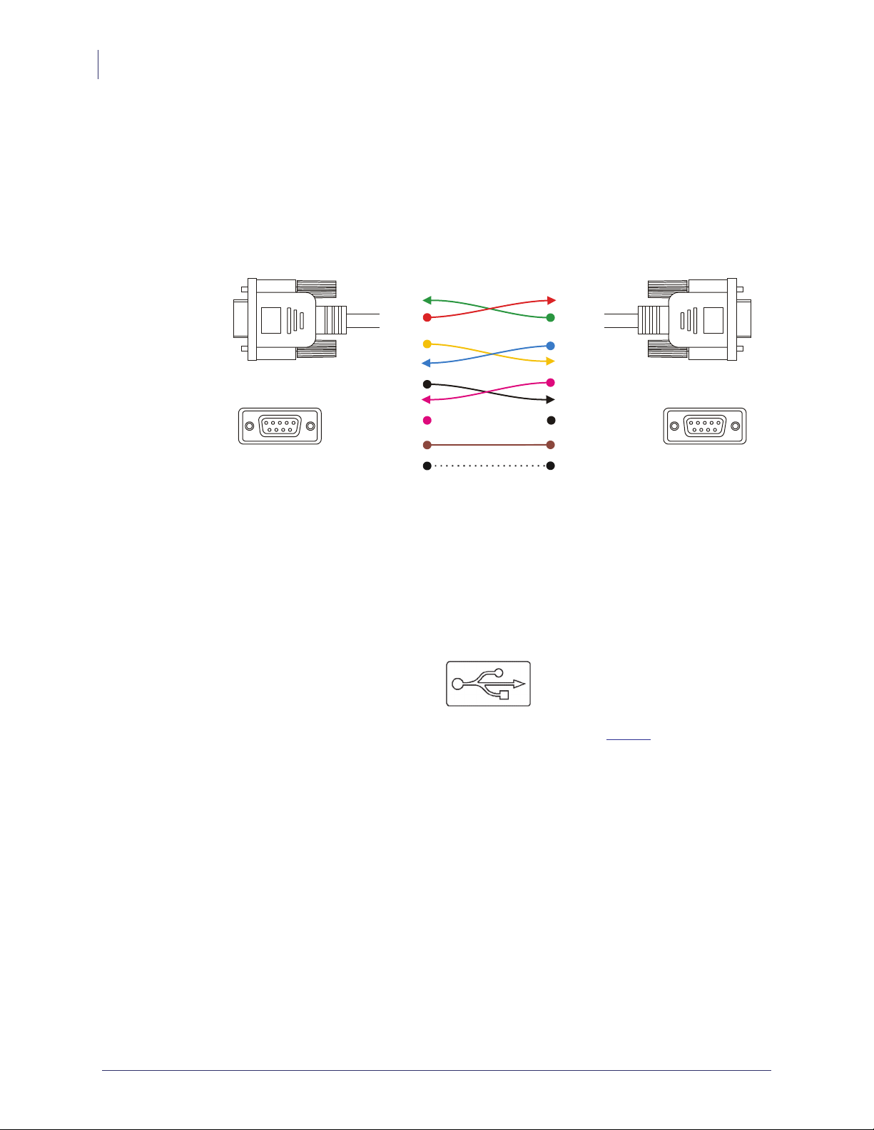
Figure 13 • Serial Interface Cable 10825-000.
2RxDRxD2
3TxDTxD3
4DTRDTR4
PC
594837261
Female
Serial Cable 10825-000
6DSRDS R6
7RTSRTS7
8CTSCTS8
1DCDDCD1
5GNDGND5
9RIRI9
Printer
594837261
Female
TTP 2130
Dotted leads are not connected in the printer. To be able to connect the cable in any direction,
make symmetrical cables.
Connect the printer to the USB port of the computer or the USB hub to be used. USB
connectors can be recognized by the following symbol:
.
The connector on the printer is a 4-pin USB type B connector. See Table 4 for pin assignment.
A suitable cable is available from Zebra, part number 105850-028.
P1003640-004 TTP 2100™ Technical Manual 09/18/2014
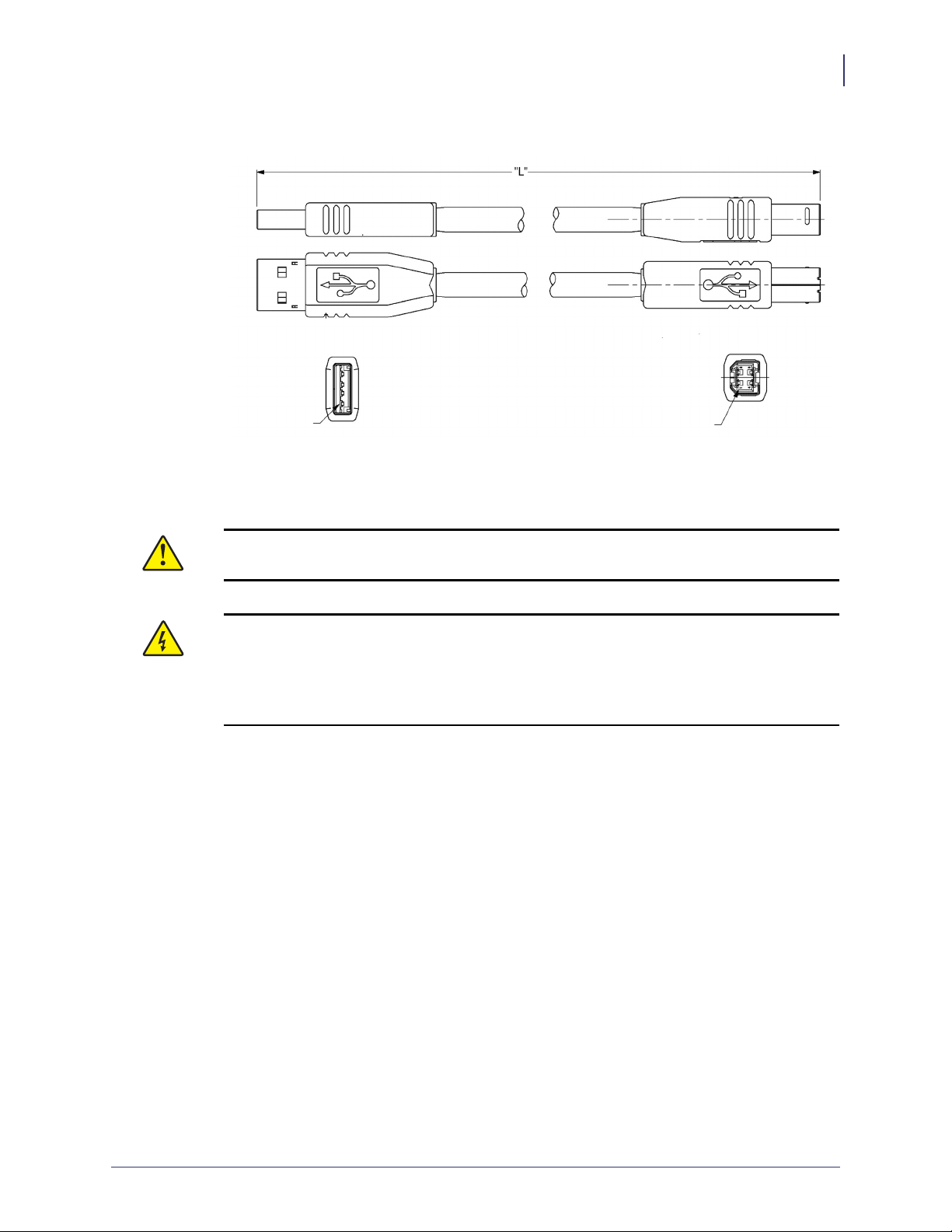
Figure 14 • USB Cable with Type A and Type B Connectors
PC Printer
Position 1 Position 1
Connecting the Power
Installation
Connecting the Power
29
Caution • Using a non-Zebra power supply may cause excessive EMC interferences and
void the EMC certifications of the printer.
Caution • To avoid electrical shock and printer damage, wiring of a non-Zebra power
supply should only be done by qualified service personnel. Use ONLY a power supply
which meets the following minimum requirements:
• 24 VDC ±5%
• 70W (2.92A)
09/18/2014 TTP 2100™ Technical Manual P1003640-004
Installation
30
Connecting the Power
Figure 15 • Location of Power Connector
Power
Connector
Caution • On power supplies with line voltage selector, make sure it is set to your local line
voltage.
Using the appropriate Zebra power supply for TTP 2100 Desktop, or Embedded (
Power
Supply):
1. Connect the cable from the power supply to the power connector on the back of the
printer.
2. Connect the power cable to the line outlet.
3. Turn ON the power.
In Kiosk applications you may draw power from a common PSU in the Kiosk if the
characteristics are suitable. In such a case, cables that fit the connector on the back of the
TTP 2100 are available from Zebra (see
Part Number List on page 133). If you make cables of
your own, connect the voltages according to the following illustration.
Note • Protective ground and minus output should not be interconnected in the power supply.
A 600 mm power cable is available from Zebra. Use this if you have a common power supply
for the entire Kiosk and power the printer from there. Use the connector shown below if you
want to make cables of other lengths. At the printer end of the cable, use a TE Connectivity
Mate-N-Lok connector housing and two contact-sockets.
P1003640-004 TTP 2100™ Technical Manual 09/18/2014
 Loading...