

Page 1
TLP2746
Mid-Range
Thermal Printers
Service Manual
980023-005 Rev.B
©2001 Zebra Technologies Corporation
Page 2

ii 980023-005 Rev.B
Page 3

CONTENTS
INTRODUCTION . . . . . . . . . . . . . . . . . . . . . . . . . . . . . . . . . . . 1
TROUBLESHOOTING GUIDE . . . . . . . . . . . . . . . . . . . . . . . . . . . . 5
REQUIRED TOOLS . . . . . . . . . . . . . . . . . . . . . . . . . . . . . . . . . . 9
REPLACING PARTS . . . . . . . . . . . . . . . . . . . . . . . . . . . . . . . . . 11
Exterior Cover . . . . . . . . . . . . . . . . . . . . . . . . . . . . . . . . . . . . . . 12
Print Head . . . . . . . . . . . . . . . . . . . . . . . . . . . . . . . . . . . . . . . .13
Power & Main PCBA Access . . . . . . . . . . . . . . . . . . . . . . . . . . . . . . . 14
Set AC Voltage . . . . . . . . . . . . . . . . . . . . . . . . . . . . . . . . . . . . . . 15
Power Supply . . . . . . . . . . . . . . . . . . . . . . . . . . . . . . . . . . . . . . . 16
AC Power Module & Switch . . . . . . . . . . . . . . . . . . . . . . . . . . . . . . . 17
Main PCBA Configuration . . . . . . . . . . . . . . . . . . . . . . . . . . . . . . . . 18
IC Installation . . . . . . . . . . . . . . . . . . . . . . . . . . . . . . . . . . . . . . . 19
Main Cable Harness . . . . . . . . . . . . . . . . . . . . . . . . . . . . . . . . . . . 21
DC Power Cable . . . . . . . . . . . . . . . . . . . . . . . . . . . . . . . . . . . . . 22
Main PCBA . . . . . . . . . . . . . . . . . . . . . . . . . . . . . . . . . . . . . . . . 23
Print Head Cable . . . . . . . . . . . . . . . . . . . . . . . . . . . . . . . . . . . . . 24
Label Guide & Sensor . . . . . . . . . . . . . . . . . . . . . . . . . . . . . . . . . . 26
Label Sensor PCBAs . . . . . . . . . . . . . . . . . . . . . . . . . . . . . . . . . . . 29
Control Panel . . . . . . . . . . . . . . . . . . . . . . . . . . . . . . . . . . . . . . .32
Head-up Sensor . . . . . . . . . . . . . . . . . . . . . . . . . . . . . . . . . . . . . 34
Label Taken Sensor. . . . . . . . . . . . . . . . . . . . . . . . . . . . . . . . . . . . 36
Door . . . . . . . . . . . . . . . . . . . . . . . . . . . . . . . . . . . . . . . . . . . 38
Peel Mechanism. . . . . . . . . . . . . . . . . . . . . . . . . . . . . . . . . . . . . . 40
Label Guide Tab . . . . . . . . . . . . . . . . . . . . . . . . . . . . . . . . . . . . . 41
Motor . . . . . . . . . . . . . . . . . . . . . . . . . . . . . . . . . . . . . . . . . . . 42
Ribbon Pulley (60 tooth) . . . . . . . . . . . . . . . . . . . . . . . . . . . . . . . . . 43
Ribbon Drive Belt . . . . . . . . . . . . . . . . . . . . . . . . . . . . . . . . . . . . . 44
Rewind Drive Pulley . . . . . . . . . . . . . . . . . . . . . . . . . . . . . . . . . . . 45
Platen Belt (120 tooth) . . . . . . . . . . . . . . . . . . . . . . . . . . . . . . . . . . 46
Platen Clutch & 42 Tooth Pulley . . . . . . . . . . . . . . . . . . . . . . . . . . . . . 47
Ribbon Collar & Spring . . . . . . . . . . . . . . . . . . . . . . . . . . . . . . . . . . 49
Ribbon Tubes & Shaft Support . . . . . . . . . . . . . . . . . . . . . . . . . . . . . . 50
Rewind Tube & Shaft Support . . . . . . . . . . . . . . . . . . . . . . . . . . . . . . 51
Platen Bearing & Replacement Kit . . . . . . . . . . . . . . . . . . . . . . . . . . . . 52
Lower Print Mechanism . . . . . . . . . . . . . . . . . . . . . . . . . . . . . . . . . . 54
Print Head Carriage. . . . . . . . . . . . . . . . . . . . . . . . . . . . . . . . . . . . 56
Cutter Cable . . . . . . . . . . . . . . . . . . . . . . . . . . . . . . . . . . . . . . . 58
Securing the Main Harness . . . . . . . . . . . . . . . . . . . . . . . . . . . . . . . . 60
Printer Configuration Check . . . . . . . . . . . . . . . . . . . . . . . . . . . . . . . 63
DC Power Verification & Adjustment . . . . . . . . . . . . . . . . . . . . . . . . . . . 64
Platen Belt and Motor Adjustment . . . . . . . . . . . . . . . . . . . . . . . . . . . . 65
Tube Tension Verify & Adjust. . . . . . . . . . . . . . . . . . . . . . . . . . . . . . . 66
Ribbon Path Adjustment . . . . . . . . . . . . . . . . . . . . . . . . . . . . . . . . . 68
Packaging for Shipment. . . . . . . . . . . . . . . . . . . . . . . . . . . . . . . . . . 70
CLEANING AND MAINTENANCE . . . . . . . . . . . . . . . . . . . . . . . . . . 71
980023-005 Rev.B iii
Page 4

FOREWORD
This manual provides maintenance, diagnosis, service and repair information for the TLP2746
printer models manufactured by Zebra Technologies Corporation, Camarillo, California.
TECHNICAL SUPPORT
If for any reason you require product technical support, please contact the Distributor where you first
purchased your equipment. If they cannot help you or at their direction, contact Zebra Repair
Administration.
RETURN MATERIALS AUTHORIZATION
Before returning any equipment to Zebra for in warranty or out of warranty repair, contact Repair
Administration for a Return Materials Authorization (RMA) number. Repack the equipment in the
original packing material and mark the RMA number clearly on the outside. Ship the equipment,
freight prepaid, to the address listed below:
Zebra Repair Administration, USA
1001 Flynn Road
Camarillo, CA 93012
Phone: +1 (805) 579-1800
FAX: +1 (805) 579-1808
Label Printers: Card Printers:
Zebra International, Europe Zebra International, Europe
Zebra House, The Valley Centre Zone Indutrielle, Rue d'Amsterdam
Gordon Road, High Wycombe 44370 Varades, France
Buckinghamshire HP13 6EQ, United Kingdom Phone: +33 (0) 240 097 070
Phone: +44 (0) 1494 472872 FAX: +33 (0) 240 834 745
FAX: +44 (0) 1494 450103
COPYRIGHT NOTICE
This document contains information proprietary to Zebra Technologies Corporation. This document
and the information contained within is copyrighted by Zebra Technologies Corporation and may
not be duplicated in full or in part by any person without written approval from Zebra. While every
effort has been made to keep the information contained within current and accurate as of the date of
publication, no guarantee is given or implied that the document is error-free or that it is accurate
with regard to any specification. Zebra reserves the right to make changes, for the purpose of
product improvement, at any time.
TRADEMARKS
TLP2746 is service mark and Zebra Technologies is a trademark of Zebra Technologies
Corporation. Windows and MS-DOS are registered trademarks of Microsoft Corp. All other marks
are trademarks or registered trademarks of their respective holders.
OPERATOR CAUTIONS AND WARNINGS
These pages describe general safety and maintenance procedures that an operator must follow.
They are referenced throughout the service manual. The manual may include other warnings and
cautions not displayed here.
iv 980023-005 Rev.B
Page 5
Warning - Shock Hazard
The printer should never be operated in a location where it can get wet.
Personal injury could result.
Warnung - Stromschlaggefahr - Der Drucker sollte nie an feuchten
Standorten in Betrieb genommen werden. Es besteht erhöhte Verletzungs
und Unfallgefahr.
Warning - Static Discharge
The discharge of electrostatic energy that accumulates on the surface of
the human body or other surfaces can damage or destroy the print head or
electronic components used in this device. DO NOT TOUCH the print
head or the electronic components under the print head assembly.
Caution - Printer Setup & Handling
1)When installing or modifying the printer setup or configuration,
ALWAYS TURN POWER OFF Before
A) Connecting any cables.
B) Performing any cleaning or maintenance operations.
C) Moving the printer.
:
2) Damage to the printer interface connector, accessories or enclosure
may result from placing the printer on it’s front bezel or backside during
unpacking or handling.
980023-005 v
Page 6
Media Cautions & Tips
1) Always use high quality Zebra approved labels and tags. Zebra approved
supplies can be ordered from your Zebra dealer. For the name of a dealer
in your area, call Zebra Customer Service at one of the numbers listed on
the back page of this manual.
2) If poor quality, adhesive backed labels are used, that DO NOT lay flat on
the backing liner, the exposed edges may stick to the label guides and
rollers inside the printer, causing the label to peel off from the liner and
jam the printer.
3) DO NOT use non-Zebra transfer ribbon. Permanent damage to the print
head may result if a non-Zebra ribbon is used. Non-Zebra ribbons maybe
wound incorrectly for the printer or contain chemicals that may damage
the print head.
4) IMPORTANT - If a transfer ribbon is installed incorrectly by the
operator, damage to the print head may result.
5) DO NOT use a ribbon when printing with direct thermal media.
Media Reload Tip
If you should run out of labels or ribbon while printing, DO NOT turn the
power switch OFF (0) while reloading or data loss may occur. The printer
will automatically resume printing when a new label or ribbon roll is
loaded.
Print Mode Control
The printer is reconfigured for direct thermal (or thermal transfer) printing
with the “O” command. See the EPL2 programmer's manual for details.
Print Quality Tip
Print density (darkness) is affected by the heat energy (density setting)
applied and by the print speed. Changing both Print Speed and Density
may be required to achieve the desired results.
vi 980023-005
Page 7

INTRODUCTION
This service manual is intended for the field service engineer or technician. It's scope covers routine
maintenance, troubleshooting and repair procedures for the printer.
Follow the parts replacement procedures as closely as possible. If you are unsure of any procedure,
please contact your service representative or call the Zebra Technologies technical support group at
(805) 579-1800. See our web site at www.zebra.com
options: printer drivers, software, firmware, FAQ's, contacts, supplies, etc..
Zebra Technologies stocks all Zebra replacement parts for the printer. Be sure your facility stocks
sufficient parts so that scheduled maintenance can take place in a timely manner.
Unpacking the Printer
Printers are carton shipped and wrapped inside a protective bag. Keep all packing materials in case
you need to reship the printer later or store the printer for any length of time.
Preparing a Static-Safe Work Area
Prepare a static-safe work area before opening the printer for repair. The area must include a
properly grounded conductive cushioned mat to hold the printer and a conductive wrist strap for the
technician. ESD protective devices are available from most electronic supply stores or by contacting
3M corporation at (800) 328-1368.
for a complete list of international support
Environmental and Shock Protection
Extreme temperature and humidity fluctuations or mishandling can damage the printer and power
supply. Allow 30 minutes or more before opening the printer's plastic bag. This time allows the
printer to stabilize temperature especially after storage in a cool, dry location and then placement in
a warmer, more humid location. Warm, humid air condenses on the cool components of the printer
and this condensation may damage the components.
Move the printer carefully. While the printer has sturdy construction, mechanical
damage can certainly result from falls or rough handling.
980023-005 Rev.A 1
Page 8
Models
Many of the earlier model Zebra printers are similar in appearance to the Zebra TLP2746 thermal
printer. The printer features that identify the TLP2746 printer from similar Zebra printers are:
Printer Color - Light Grey
•
Flash Programmed Printer Memory - No Memory Cartridge (see the rear panel of printer)
•
Carbon Fiber (Black) 1 inch (inner diameter) Media Roll Holder
•
Label Dispense (Peel) and Batch Mode Switch (see the rear panel of printer)
•
A High Tension Label Dispense (Peel) Mechanism
•
Head-Up Sensor (small sensor slot in the center panel)
•
300 Watt Power Supply
•
Expanded Language Support (14 MS DOS™ and 7 Windows™ code pages)
•
Industry Standard Bar Code including PDF417 and Maxicode two dimensional bar codes
•
Memory Expansion up to 1 MByte (Flash) and 512 SRAM (Image Buffer)
•
Optional Asian Language Support - Today, including Japanese, Chinese and Korean
•
Optional Cutter
•
Optional Real Time Clock (RTC) with a ten year battery life
•
TLP2746
Printers with thermal transfer printing have ribbon
tubes above the print head mechanism and can
print in Direct Thermal or Thermal Transfer print
modes.
See service procedure 980023-150 to help you identify installed printer features and modes.
2 980023-005 Rev.A
Page 9
Conventions
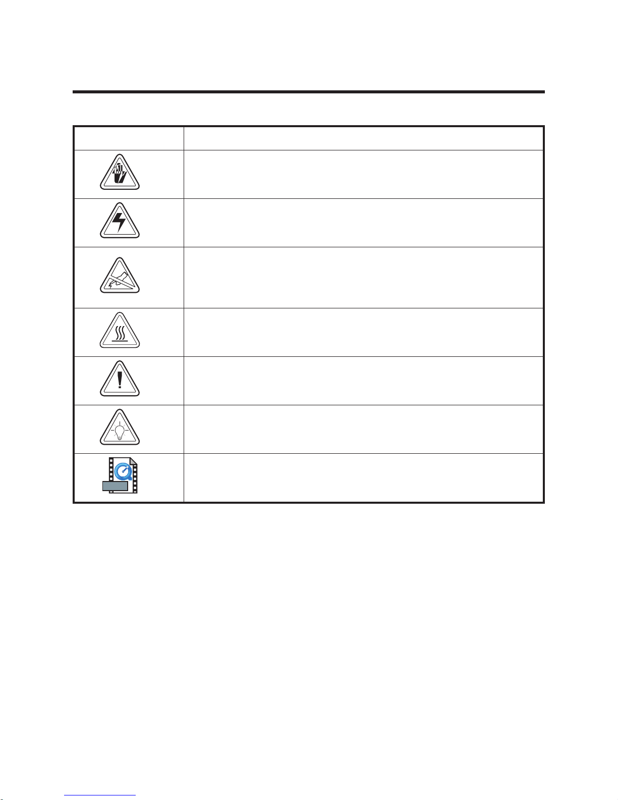
This manual uses the following notations to call attention to important information.
ICON / SYMBOL MEANING
WARNING - critical safety information.
CAUTION - problem avoidance messages.
STATIC SENSITIVE - follow procedures that protect against the discharge
of electrostatic energy that accumulates on the surface of the human body
or other objects as this discharge can damage or destroy the print head
and other electronic components.
HEAT - The print head becomes hot while printing. Protect against
personal injury. DO NOT touch the print head. Use only the cleaning
pen to perform maintenance.
MOVIE
NOTE - important instructions and reminders.
HINT - helpful information.
Quicktime Movie - Click on this Icon in the electronic version of this
manual for an instruction video.
980023-005 Rev.A 3
Page 10

4 980023-005 Rev.A
Page 11

TROUBLESHOOTING GUIDE
PROBLEMS SOLUTIONS
With the STATUS
indicator light GREEN,
the printer appears to
be working, but nothing
is printed.
Status indicators do
not light when power
switch is on (I)
Printer appears to be
working with the
indicator light
GREEN, but nothing
is printed.
1. Verify the labels are the correct type.
2. Check the roll and verify that the print surface faces up for printing.
3. Check the transfer ribbon is correctly routed and has the ink side out
for thermal transfer printing, only.
1. Check power connections from the printer to the outlet.
2. Remove power supply and check fuse. If blown, replace the power
supply.
3. Verify power supply voltage settings, AC input voltage (110VAC or
220VAC), and DC voltage (980023-152).
4. Printer works, but no indicator light. Replace the control panel.
1. Check the connections between the printer and the cable as well as
the cable and the computer.
2. Verify the labels are the correct type.
3. Check the roll and verify that the print surface faces up for direct
thermal printing.
4. Check the transfer ribbon is correctly routed and has the ink side
down.
5. Check print head wire bundle connections at main PCBA.
980023-005 Rev.A 5
Page 12

PROBLEMS SOLUTIONS
1. Wipe the print head with the cleaning pen.
2. Adjust print speed/darkness in software or with programming.
Printing is uniformly
faded or poor quality.
3. Check the roll and verify that the media print surface is facing up.
4. Verify the correct combination thermal transfer ribbon and media are
in use.
Printing has streaks,
white (non printing)
lines, uneven printing
(a side or sides), or
faded print areas.
Printing stops and the
STATUS indicator
lights RED.
1. Wipe the print head with the cleaning pen.
2. Use the "SAVE-A-PRINTHEAD" cleaning film (P/N 44902)
contamination build-up.
3. The head may be worn out and needs to be replaced.
4. Static damage from touching the head has blown out pixels or the
electronic logic circuitry in the print head assembly. Replace the head
or secondarily the main board.
5. The main board has failed components.
6. The print head cable is loose or damaged.
1. Possible problem sensing labels with transmissive (gap) sensor.
Perform AutoSense adjustment. Align the transmissive (gap) sensor
position, see the user’ manual.
2. Possible problem with label media.
a) Gap between the bottom of a label and the top of the next label
should be at least 1/16" (1.6mm).
b) For tags, see Tag Media Sensing, page .
c) Use only Zebra approved labels and tags.
3. Possible label jam.
4. Check that the media is correctly routed.
5. Possible software/programming problem.
a) Check the printer memory configuration.
b) Refer to the EPL2 Programming manual for the correct data
syntax.
6. Transmissive sensor is dirty. Clean the media path.
Printer is in dump
mode but nothing
1. File does not contain a form feed code that will advance sheet. Press
prints after sending
file.
ASCII characters print
1. Printer may be in dump mode. Press the Feed button to reset to
in place of expected
label art and bar
2. Check serial port configuration using the Y command. See the EPL2
codes.
6 980023-005 Rev.A
the Feed button to print data in the printer’s buffer.
normal operation.
programmer’s manual.
Page 13

PROBLEMS SOLUTIONS
1. Align the transmissive (gap) sensor near the narrowest gap between
labels.
2. Perform the AutoSense adjustment.
Printing stops and
status indicator lights
red
3. Check that gap between labels is at least 1/16 inch (1.6mm)
4. For tags, see the discussion of Tag Media Sensing.
5. Check for media jam.
6. Check media is correctly routed.
7. Check printer memory configuration and correct data syntax.
8. Transmissive (gap) is dirty. Clean media path.
1. Check for out-of-media condition or missing labels in the middle of a
roll.
2. Check for out-of-ribbon condition or damage or previous use of
ribbon in middle of roll.
Status indicator
remains red.
3. Check the ribbon and label stock or correctly routed
4. If using direct thermal printing, check that programmed mode or
printer driver is set for direct thermal printing. See the programmer’s
book for details.
5. Transmissive (gap) sensor may be dirty. Clean media path.
6. Check the printer carriage is closed and latched.
Rubbing noise when
pressing Feed button.
Cutter makes
incomplete cuts or
cuts in the wrong spot.
1. Media is not loaded and the platen is rubbing against the print head.
Insert media (and load ribbon if necessary) between carriage and
platen.
1. Printer is set for dispense/peel mode. Move switch to batch position.
2. Form length is set wrong. Change length through printer driver or
programming language. See the EPL2 programming manual.
The printer firmware is updated by way of the parallel port.
1. Use the download utility to send firmware to the printer.
Printer firmware must
be updated.
2. Optionally, you can download from the c:\ prompt by typing
copy/b filename lpt1: from the directory holding the update file.
The printer's light should start flashing green-orange, and then every few
seconds will flash red a couple of seconds. Once the update is done, the
light goes dark then comes on green.
Print Head Life
The print head has a limited life and is considered a consumable item. The media rubs across the
print head print elements and wears away the surface. This process is affected by many factors
relating to the media material, operational settings and environment. To maximize your print head
life, use the "SAVE-A-PRINTHEAD" cleaning film (P/N 44902) contamination build-up after every
roll.
980023-005 Rev.A 7
Page 14

Identifying Print Head Problems
The print head wears with printer use. If the print quality does not improve after cleaning, the print
head may require replacement. Printing with worn damaged print elements may create unreadable
bar codes. Print head damage can be caused by improper cleaning (unapproved fluids or
implements), electro static discharge (ESD), and touching the print head (contaminates, ESD and
body oil acids). The following are examples of print head wear or damage.
Weak or Damaged Print Elements
(Full-On Print Pattern)
Weak or Damaged Print Elements or Print Logic
(Rotating Print Element Pattern)
8 980023-005 Rev.A
Page 15

REQUIRED TOOLS
Make use of the following tools while performing replacement procedures:
Torque wrench with 1/4" hex receptacle)
•
Phillips driver #1 (tip for 1/4" hex receptacle)
•
Phillips driver #2 (tip for 1/4" hex receptacle)
•
•
Allen key socket tip drivers (tip for 1/4" hex receptacle);
sizes: 1/16", 5/64", 3/32", 1/8", 4mm
•
Nut driver, sizes: 7mm, 8mm, 1/4"
•
Flat Blade screwdriver (small)
•
needle-nose pliers
•
pliers for E-ring retainers (12R)
•
pliers for axial retainers
•
pliers for integrated chips
•
tweezers
•
Clutch torque bit (and torque gauge are spare 105902-060)
•
.005" shim
•
Loctite 222 thread locker or equivalent
980023-005 Rev.A 9
Page 16

10 980023-005 Rev.A
Page 17

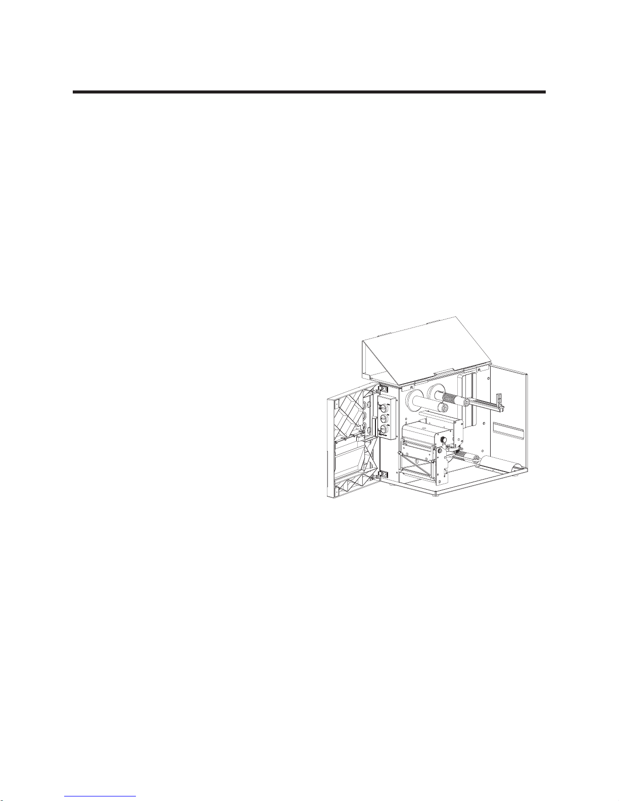
REPLACING PARTS
To access some parts, you need to dissemble other parts; therefore, other procedures must be
followed before and after performing a particular replacement.
MOVIE
980023-005 Rev.A 11
Page 18
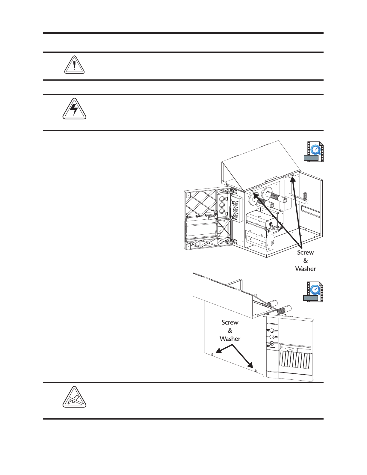
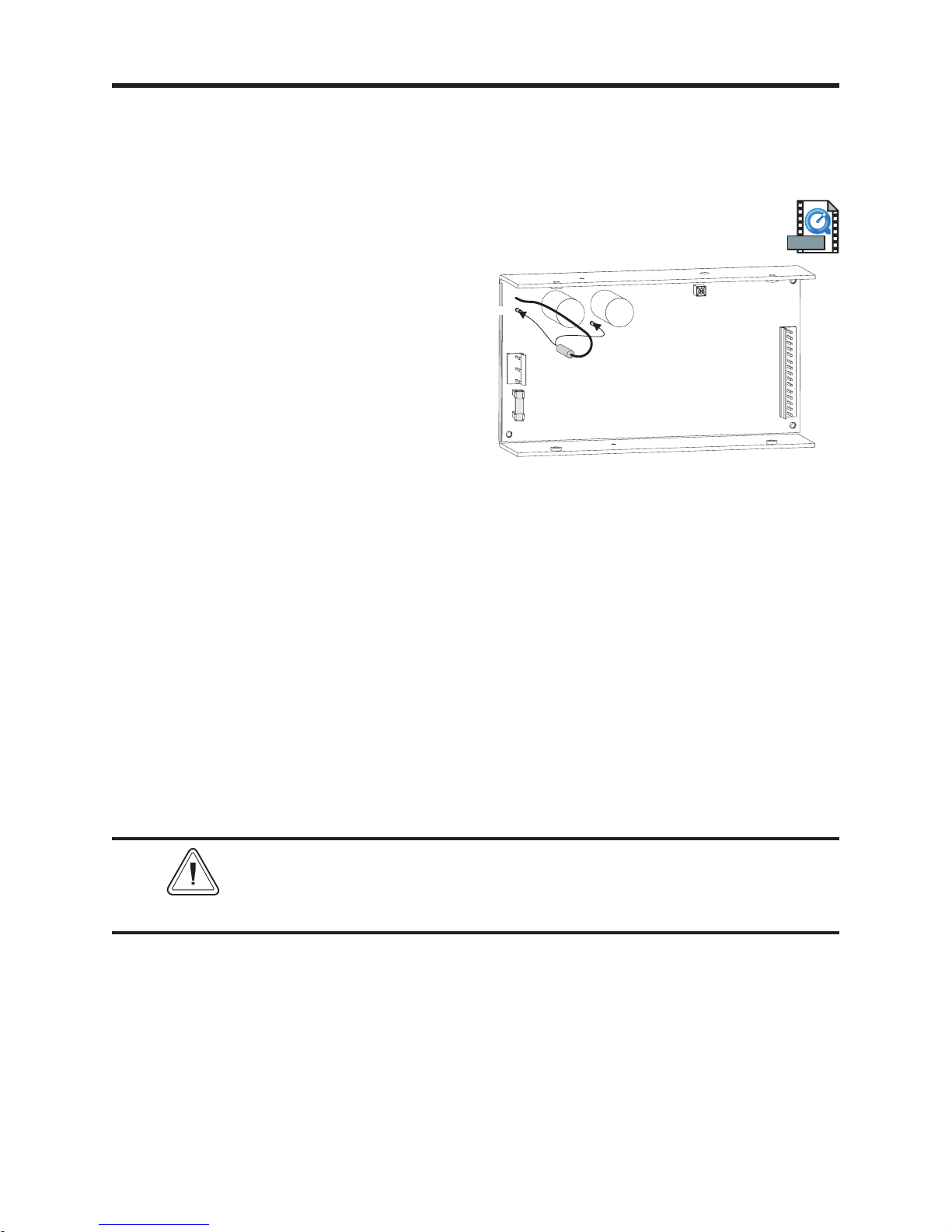
Exterior Cover
Preparations
The printer's exterior cover needs to be removed to perform most of
the disassembly and replacement procedures for the printer.
NOTE
Before starting the procedure, open the printer, then remove media and any ribbon from the printer.
Shock Hazard
Always turn off the printer before performing any maintenance or
repair operations. Wait for the indicator light to be dark, then unplug
the power cord.
Tools:
#2 Philips screw driver
Removal
1. Remove the two (2) upper screws and two
(2) lower screws shown. Lift the cover off.
Installation
1. Place the cover in position. Secure the cover
with the two (2) upper screws (and washers)
and the two (2) lower screws (and washers)
shown
MOVIE
MOVIE
Protect against static discharge when handling the printer with the
cover removed. Your work area must be static-safe and should
include a properly grounded conductive cushioned mat to hold the
printer and a conductive wrist strap for yourself.
12 980023-101 Rev.B
Page 19
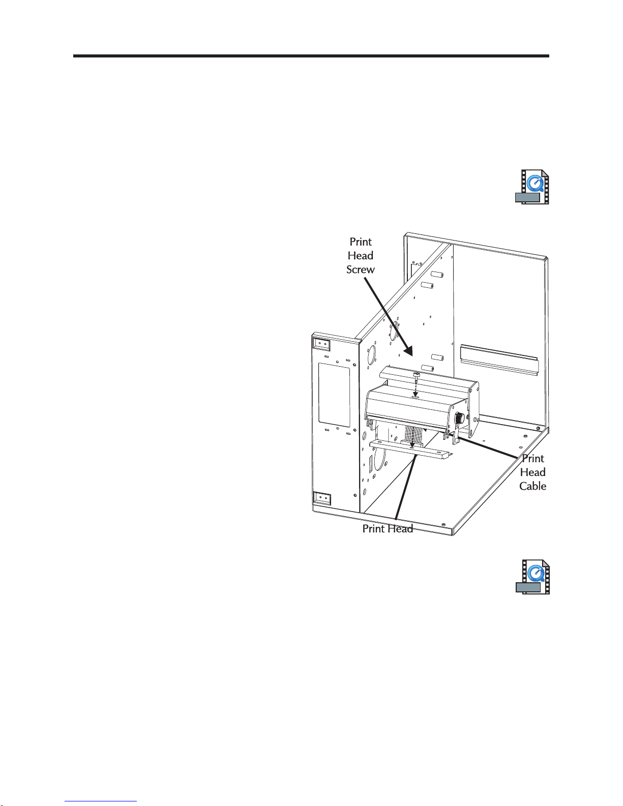
Print Head
Preparations
Before starting the procedure, open the printer, then remove media and any ribbon from the printer.
Tools:
Flat blade screw driver
Removal
1. Open the print head assembly.
2. Lower the print head by loosening the
mounting screw accessed through a hole in
the top of the print head assembly.
3. Detach the print head (ribbon) cable.
Installation
1. Connect the replacement print head. Pin 1
on the print head and cable is toward the
center panel of the printer.
2. Align the print head with the two bracket
alignment pins.
3. Secure print head to print head bracket by
tightening the print head bracket screw.
Tighten the screw to 4.7 ±1 in. lb.
MOVIE
4. Close and open the print head and recheck
that the print head cable still secure and
connected to the print head.
5. Clean the print head after completing
installation.
980023-102 Rev.B 13
MOVIE
Page 20
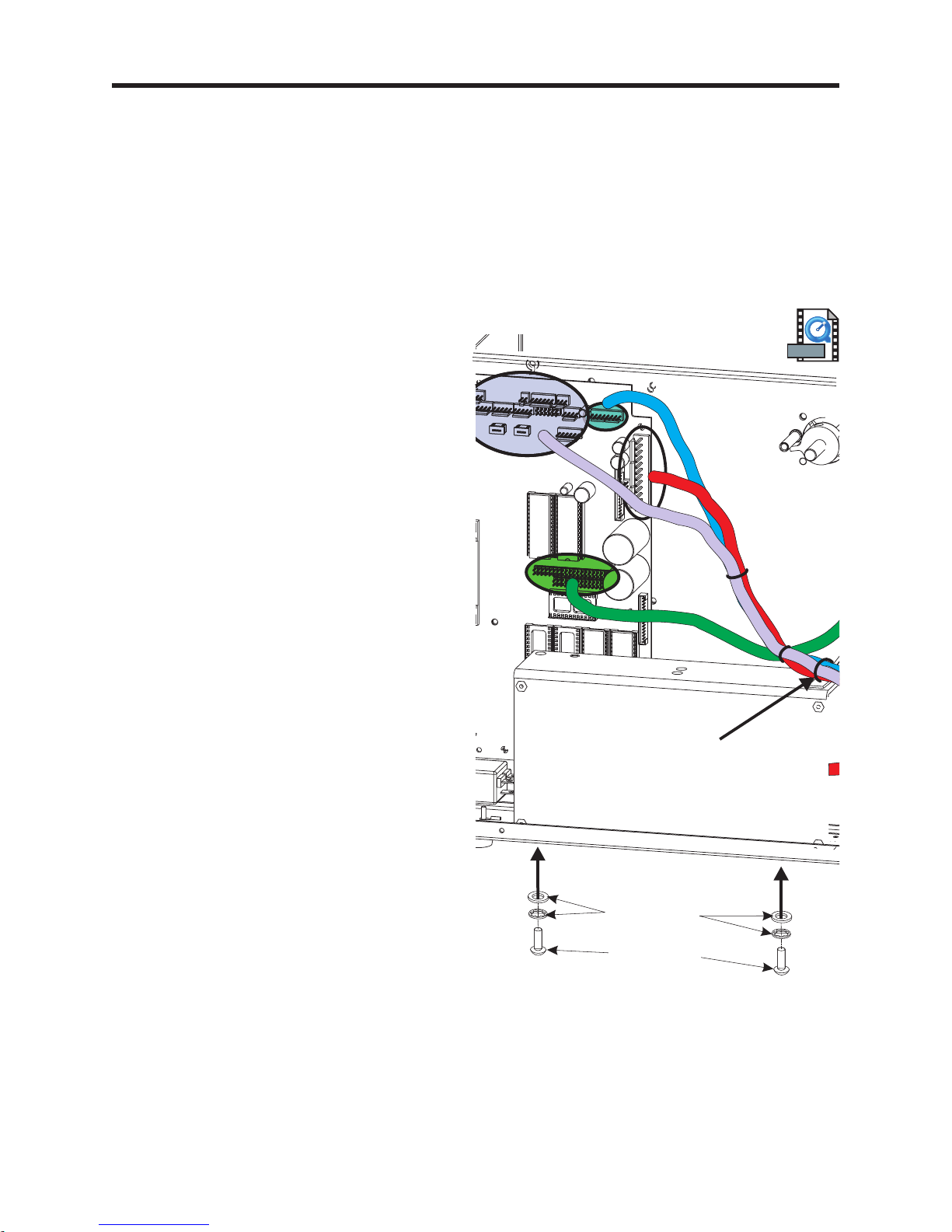
Power & Main PCBA Access
Preparations
The exterior cover must be removed prior to proceeding. (980023-101)
Tools:
#2 Philips screw driver
1. For easier access to the power supply and
Main PCBA, remove the two (2) screws
securing it to the bottom of the printer
chassis.
With the printer on it's right side, hold the
power supply while removing the two (2)
screws (and washers) that secure it to
bottom panel.
2. Disconnect the AC input power connector
plug from the power supply. This allows
easier access to the power supply without
disassembling the cabling and cable ties.
3. Swing the power supply out to gain access
to the voltage setting jumper.
MOVIE
WASHERS
SCREWS
Set the power supply down gently on the
printer base to keep the supply from
swinging into the Main PCBA and
damaging components.
Caution - The connectors or the cable's tie
down may come loose or inadvertently
disconnected if special care is not taken.
14 980023-103 Rev.B
Page 21
Set AC Voltage
Preparations
The exterior cover must be removed prior to proceeding. (980023-101)
The power supply must be detached from the bottom panel for access. (980023-103)
Set Voltage
1. Move the voltage selection jumper wire to
the appropriate voltage pin. Verify the
correct voltage is marked next to the
jumpers pin.
Re-assemble Printer
2. Remount the power supply using the screws
and washers. Keep the power supply from
swinging into the Main PCBA and
damaging components.
3. Verify that the cables and ties have not
become loose or damaged. Verify that the
cable tie points have not moved, allowing
the cables to touch belts or gears.
230VAC
AC
Input
110VAC
MOVIE
1
DC
Supply
Voltage
to PCBA
4. Re-attach the exterior cover.
Fuse Warning
If the power supply's fuse has blown, the power supply most likely has
NOTE
a critical component failure. Most cases require power supply
replacement.
980023-104 Rev.B 15
Page 22
Power Supply
Preparations
The exterior cover must be removed prior to proceeding. (980023-101)
The AC input power voltage (jumper) should be set prior to installing the power supply.
(980023-104)
Some power supplies come with DC power cables and may also require changing. (980023-113)
Tools:
#2 Philips screw driver
Removal
1. Cut the tie-wrap securing the cables to the
top of the power supply. Caution - Do not
cut the cables!
2. With the printer on it's right side, hold the
power supply while removing the two (2)
screws (and washers) that secure it to
bottom panel. Set the power supply down
gently on the printer base to keep the supply
from swinging into the Main PCBA and
damaging components.
3. With printer upright, tilt the power supply
outward to rest on it's side.
4. Disconnect the two (2) cables and remove
the power supply.
Installation
1. Verify the power supply voltage setting.
Reconfigure the power setting as necessary.
MOVIE
Cut
2. Set the replacement power supply in
position. Reconnect power cables.
3. Remount the power supply the screws and
washers.
5. Attach a new cable tie to the anchor on the
power supply (top front outside corner).
Loop a new cable tie through the cable
anchor and re-attach the cable bundle to
the power supply chassis.
16 980023-105 Rev.B
WASHERS
SCREWS
Page 23
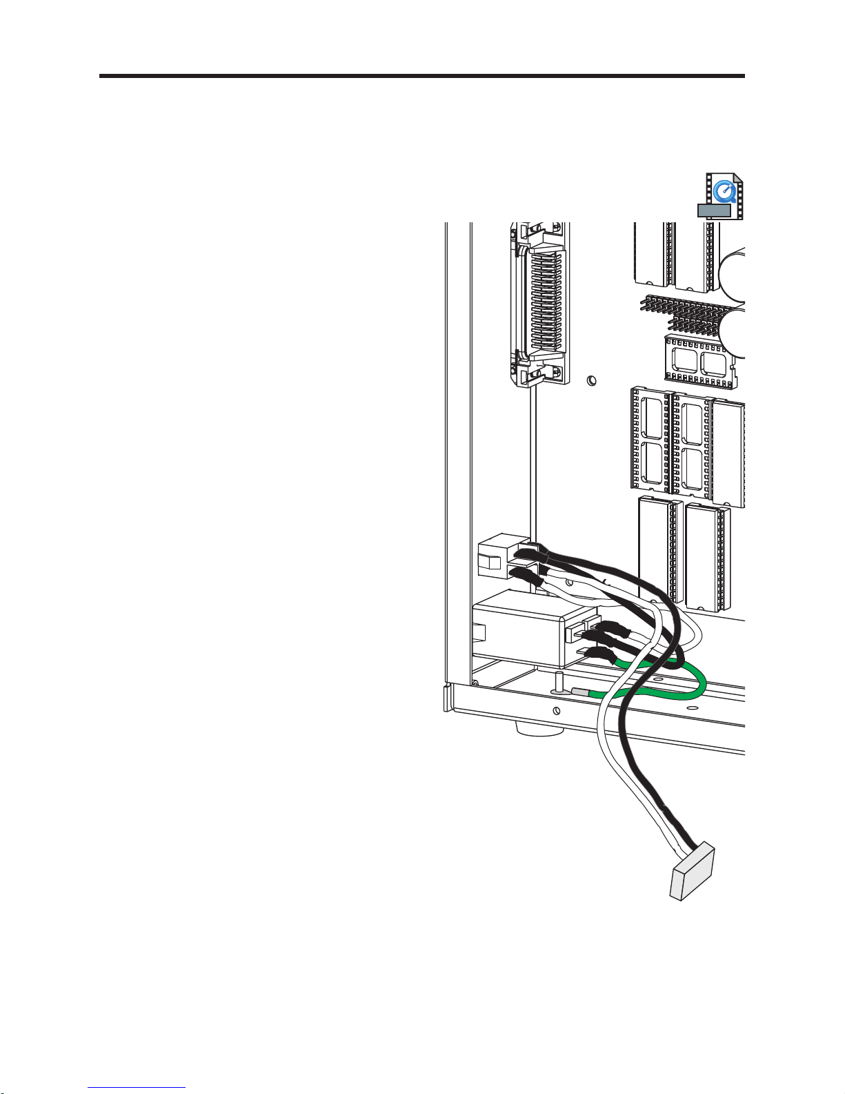
AC Power Module & Switch
Preparations
The exterior cover must be removed prior to proceeding. (Procedure 980023-101)
The power supply must be unscrewed from the printer's bottom plate. (Procedure 980023-103)
Power Switch Removal
1. Push the retaining tabs into the side of the
power switch or AC power filter module
and slide the switch out of the back panel.
Power Switch Installation
1. Disconnect the old switch's wires, one at a
time, and reconnect them to the new switch
in the same position. Note the switch's
orientation, 1 (one) to the outside and 0
(zero) towards the center panel.
MOVIE
2. Push the new switch into the back panel
until flush with the back panel. Wiggle it
from the inside to very that it has locked in
place.
AC Module Removal
1. Push the retaining tabs into the side of the
AC power filter module and slide the
module out of the back panel.
AC Module Installation
1. Disconnect the old module's wires, one at a
time, and reconnect them to the new switch
in the same position. Note the module's
orientation, ground towards the bottom
plate.
2. Push the new module into the back panel
until flush with the back panel. Wiggle it
from the inside to very that it has locked in
place.
980023-106 Rev.B 17
Page 24
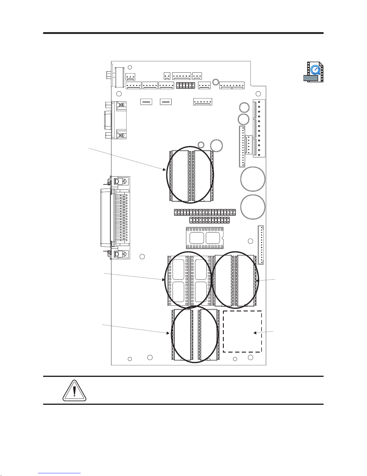
Main PCBA Configuration
The following diagrams the printer's physical location for the memory and real time clock (RTC)
chips.
Print Engine
Firmware
MOVIE
Extended Image
Printer SRAM
(in Spare PCBA's also)
Image Engine
Firmware
U14
U31
U24
U13
U2
U18
U25
U26
U34
&
U33
U27
Standard Image
Printer SRAM
(Spare PCBA's also)
Asian Language
Flash Firmware
(in Spare PCBA's also)
To identify the printer's Main PCBA configuration without opening
the printer, use the printer's AutoSense procedure.
18 980023-109 Rev.B
Page 25

IC Installation
Preparations
The exterior cover must be removed prior to proceeding. (Procedure 980023-101)
The power supply must be unscrewed from the printer's bottom plate. (Procedure 980023-103)
Tools:
IC Chip Removal Tool
Replacing the Integrated Circuit Chips
To replace a chip, use the following procedure:
1. Use I.C. chip pliers to pull the chip out of its socket on the main PCBA.
2. Carefully align each chip and insert it into the main PCBA. Check that all pins are in their
holes.
IE Flash 1MB Upgrade
Replace the image engine flash chips at
locations U25 and U24.
IE Flash stores pre-designed elements
(fonts, forms and graphics) that go into a
print job plus some operation code for the
printer.
Print Engine Upgrade
MOVIE
Replace the print engine flash chips at
locations U13 and U14.
IE Flash stores pre-designed elements
(fonts, forms and graphics) that go into a
print job plus some operation code for the
printer.
980023-110 Rev.B 19
Page 26

SRAM 512KB Upgrade
You add two RAM chips into empty sockets,
U18 and U31.
SRAM provides image buffer for the printer.
A larger SRAM capacity allows for larger
and longer images.
Real Time Clock Option
Add the real time clock option chip into the
socket at location U2.
The real time clock option stores the time of
day and date. The chip's battery has a life
of up to ten years.
MOVIE
See the EPL2 Programmer's Manual
for information about setting the real time
clock, and formatting the layout of the date
and time.
Re-assembling the Printer
1. Reattach the power supply.
2. Reconnect the AC power input plug.
3. Reattach the printer cover.
4. Attach the power cord and interface cable.
20 980023-110 Rev.B
Page 27

Main Cable Harness
The following diagrams the physical location of the printer's primary cable groups and cable tie
points.
Controls and
Sensors
Motor
DC Power
Print Head Cable Ties Cable Tie
980023-112 Rev.B 21
and
Anchor
Page 28

DC Power Cable
Preparations
The exterior cover must be removed prior to proceeding. (980023-101)
Note the main cable harness routing and cable tie positions. (980023-112)
Removal
1. Cut the three (3) tie-wraps securing the
main cable harness. Caution - Do not cut
the cables!
MOVIEMOVIE
2. Disconnect the power cable (JP6) from
main PCBA.
3. Disconnect the power cable from the power
supply.
Installation
1. Connect the power cable (JP6) to the main
PCBA.
2. Connect the power cable to the power
supply.
3. Re-tie the main PCBA harness. Use the
"Securing the Harness" procedure.
DC Power
JP6
22 980023-113 Rev.B
Page 29

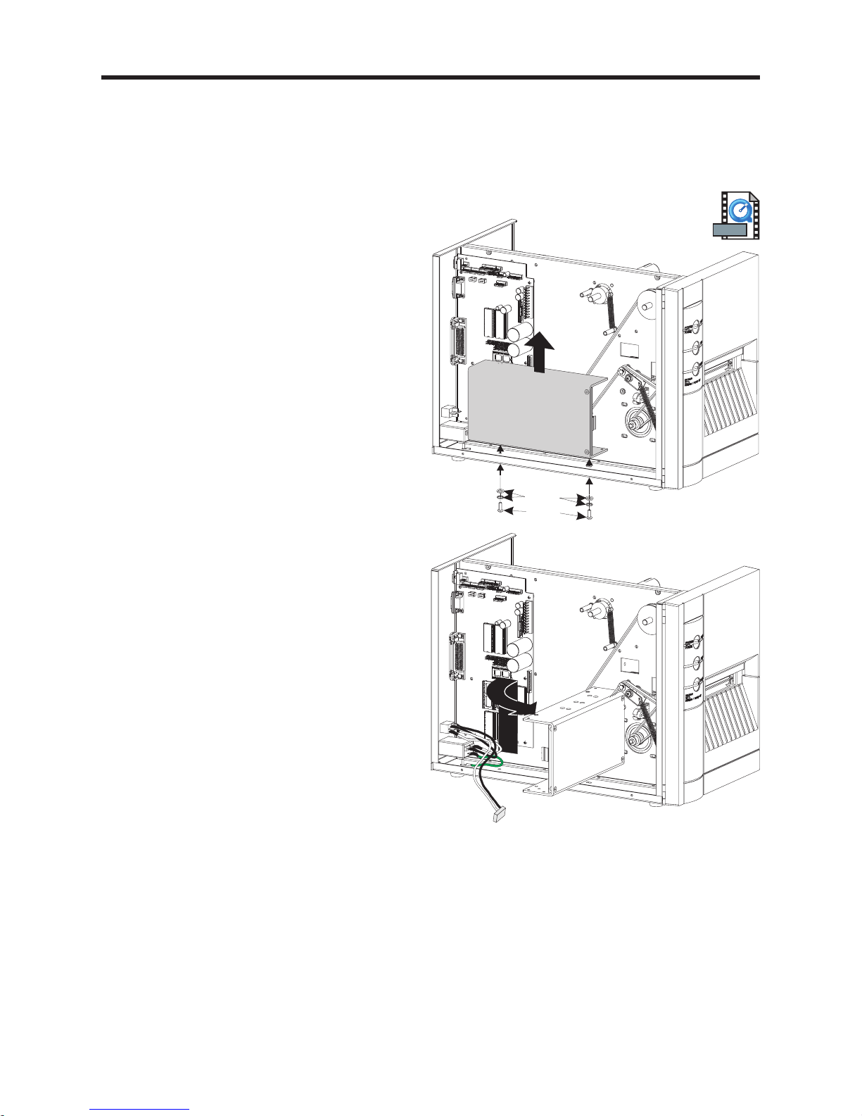
Main PCBA
Preparations
The exterior cover must be removed prior to proceeding. (980023-101)
The power supply must be loosened from the printer's bottom plate. (Procedure 980023-103)
Tools:
#1 Philips screw driver
Removal
1. Disconnect the cables from the main PCBA.
2. Disconnect the motor, DC power, and the
print head cables from the main PCBA.
3. Remove the two (2) mounting screws
holding the main PCBA to the center panel.
4. With the sensor and control cables still
attached to the main PCBA, gently lift the
main PCBA off the stand-offs.
5. Set the old main PCBA gently aside, next to
the power supply. Have care not to
disconnect the sensor and control cables.
Installation
1. Mount the main PCBA on the stand-offs.
2. Secure the main PCBA to the center panel
with the two (2) mounting screws.
MOVIE
Screws
3. Swing the old main PCBA next to with both
board sensor and control connectors and
cables accessible.
4. From right to left and one at a time,
disconnect the sensor and control cables
from the old board to the new main PCBA.
5. Remount the power supply the screws and
washers. Reconnect the AC power plug to
the power supply.
6. Connect the motor, DC power, and the
print head cables to the new main PCBA.
7. Re-install the case.
980023-115 Rev.B 23
Page 30

Print Head Cable
Preparations
The exterior cover must be removed prior to proceeding. (980023-101)
Removal
1. Cut the center tie-wrap securing the main
cable harness. Caution - Do not cut the
cables!
2. Disconnect the print head cable (JP21) from
main PCBA.
MOVIE
24 980023-116 Rev.B
Pin 1 of JP21
Print Head
Connector
Page 31

3. Open the print head assembly.
4. Lower the print head by loosening the
mounting screw accessed through a hole in
the top of the print head assembly.
5. Detach the print head (ribbon) cable. Set
the loose print head on a clean, soft and
static safe surface (mat).
6. Pull the cable out through the center panel.
7. Remove the cable's spiral wrap.
Installation
1. Place the spiral wrap on the new cable.
2. Connect the cable to the JP21 on the main
PCBA. Note pin 1 on the connector and
cable. Slide the spiral wrap 2" from the print
head end of the cable.
3. Route the cable through the center panel.
Lower the print head for easier access.
4. Connect the print head. Pin 1 on the print
head and cable is toward the center panel.
5. Align the print head with the two bracket
alignment pins.
6. Secure print head to print head bracket by
tightening the print head bracket screw.
Tighten the screw to 4.7 ±1 in. lb.
7. Close and open the print head and recheck
that the print head cable still secure and
connected to the print head. Verify that 1/4
is inside and 3/4 of the spiral wrap is outside
of the center panel. This protects the cable
from rubbing on the belt and print head
carriage.
8. Re-tie the main PCBA harness. Use the
"Securing the Harness" procedure.
MOVIE
9. Clean the print head after completing
installation.
980023-116 Rev.B 25
Page 32

Label Guide & Sensor
Preparations
The exterior cover must be removed prior to proceeding. (980023-101)
Note the main cable harness routing and cable tie positions. (980023-112)
The Label Guide & Sensor assembly is mounted below the print head assembly. The sensor slide
and cables pass through the center panel of the printer chassis and plug into the main PCBA.
Tools:
#2 Philips screw driver
Removal
1. Cut the three (3) tie-wraps securing the
main cable harness. Caution - Do not cut
the cables!
2. Disconnect the label guide and sensor
cables (JP27, JP28, JP4 and JP5) from
main PCBA.
3. From the user’s access area (right side of
printer), open the print head with the print
head's release latch.
Adjust the sensor slide to the outside
position, away from the center panel of the
printer chassis.
4. Remove the pan head screw securing the
label guide and sensor assembly to center
panel of the printer chassis (user access
side).
JP27
JP5
JP4
JP28
MOVIE
26 980023-117 Rev.B
Screw
Release Latch
Page 33

5. Slide the label guide and sensor assembly
toward the front of the printer, (approx. 1/4"
parallel to the center panel) and pull the
assembly out away from the center panel
when it clears the panel.
Pull the sensor cables out through the center
panel.
980023-117 Rev.B 27
Page 34

Installation
1. Slide the sensor guide's four (4) cables
through the sensor slide’s hole.
2. Insert and hook the label guide’s tab onto
the center panel’s cut-out.
3. Secure the label guide and sensor assembly
to the center panel with the pan head screw.
4. Close the print head.
Hook guide to center panel
5. Re-connect the cables (JP27, JP28, JP4 and
JP5) to the Main PCBA. The five (5)
conductor cable exiting the bottom of the
sensor slide gets connected to JP5.
5 conductor - JP4
(middle set)
6. Re-tie the main PCBA harness. Use the
"Securing the Harness" procedure.
3 conductor - JP27
2 conductor - JP28
5 conductor - JP5
(bottom set)
28 980023-117 Rev.B
Page 35

Label Sensor PCBAs
Preparations
The exterior cover must be removed prior to proceeding. (Procedure 980023-101)
Note the main cable harness routing and cable tie positions. (980023-112)
Remove the Label Sensor and Guide Assembly from the printer. (980023-117)
Tools:
#2 Philips screw driver
Removal
1. Slide the sensor adjustment slide into the
sensor housing.
MOVIE
2. Remove the three (3) screws attaching the
lower housing to the upper.
3. Gently rock the lower housing while slowly
pulling lower housing and slide parallel to
the upper housing.
980023-118 Rev.B 29
Page 36

4. Completely slide the lower and upper
housings from the slide.
5. Remove the adhesive securing the cables at
the end of the slide. Caution - Do not
damage the slide or good cables or
good PCBAs.
6. Slide the appropriate cable out of the cable
clips. Note how the cables are attached and
routed.
7. While holding the slide to keep it from
spreading apart, gently pull the appropriate
PCBA from the slide.
Installation
Gap Receiver / Ribbon Out PCBA
Cable Clips
Cable Clips
Gap Emitter / Black Mark PCBA
1. Press the new PCBA onto the slide with the
components and cables facing up.
2. Route the cables flat against the slides
without twists and under the cable clips.
Cable Routed
Under Clips
30 980023-118 Rev.B
Page 37

3. Add adhesive (hot melt glue or RTV) to the
end of the slide to secure the cables to the
slide. Remove excess adhesive immediately.
let the adhesive set before continuing.
4. Slide the sensor adjustment slide half way
into the lower housing.
5. Insert the cables into the slide access in the
upper housing.
6. Finish sliding the two housings together.
Gently rock the lower housing while slowly
pushing the lower housing into the upper
housing.
7. Re-attach the lower housing to the upper
with the three (3) screws.
8. Install the label guide and sensor assembly
using the "Label Guide & Sensor"
procedure.
980023-118 Rev.B 31
Page 38

Control Panel
Preparations
The exterior cover must be removed prior to proceeding. (980023-101)
Note the main cable harness routing and cable tie positions. (980023-112)
Tools:
#1 Philips screw driver
Removal
1. Cut the three (3) tie-wraps securing the
main cable harness. Caution - Do not cut
the cables!
2. Disconnect the control panel cables (JP35)
from main PCBA.
3. Cut the tie wrap holding the three (3)
ribbon cables to the back of the control
panel's PCBA. Caution - Do not cut the
cables!
JP35
MOVIE
4. Remove the two (2) screws retaining the
control panel assembly.
5. Open the front door and pull the control
panel assembly straight out the front panel
of the printer.
32 980023-119 Rev.B
Cut Cable Tie
Screws
Page 39

Installation
1. Insert the control panel cable into the
control panel's access hole.
2. Slide the control panel's four (4) guide posts
into the front panel.
3. Attach the control panel assembly to the
inside of the front panel with the two (2)
retaining screws. Tighten to
4.7±1inch-pounds of torque.
4. Place the adhesive backed tie anchor on the
back of the control panel PCBA, as shown.
5. Group the three cables (control panel,
head-up, and label taken sensor) into a
harness bundle and lock the them to the
anchor with a cable tie.
MOVIE
Control
Panel
Cable
Verify the head-up sensor cable is not
twisted and easily clears the ribbon drive
belt.
6. Connect the control panel cable to the main
PCBA at header JP35.
7. Re-tie the main PCBA harness. Use the
"Securing the Harness" procedure.
Place Tie
Anchor & Tie
Cables
980023-119 Rev.B 33
Page 40

Head-up Sensor
Preparations
The exterior cover must be removed prior to proceeding. (980023-101)
Note the main cable harness routing and cable tie positions. (980023-112)
Removal
1. Cut the three (3) tie-wraps securing the
main cable harness. Caution - Do not cut
the cables!
2. Disconnect the head-up cable (JP14) from
main PCBA.
3. Cut the tie wrap holding the three (3)
ribbon cables to the back of the control
panel's PCBA. Caution - Do not cut the
cables!
JP14
MOVIE
4. Pull the head-up sensor PCBA stand-offs.
34 980023-121 Rev.B
Cut Cable Tie
Head-Up
Sensor
PCBA
Page 41

Installation
1. Insert the head-up sensor PCBA onto the
stand-offs with the cable facing out and
toward the front of the printer.
2. Group the three cables (head-up, control
panel, and label taken sensor) into a
harness bundle and lock the them to the
anchor with a cable tie.
Verify the head-up sensor cable is not
twisted and easily clears the ribbon drive
belt.
3. Connect the control panel cable to the main
PCBA at header JP14.
4. Re-tie the main PCBA harness. Use the
"Securing the Harness" procedure.
Place Tie
Anchor & Tie
Cables
980023-121 Rev.B 35
Page 42

Label Taken Sensor
Preparations
The exterior cover must be removed prior to proceeding. (980023-101)
Note the main cable harness routing and cable tie positions. (980023-112)
Tools:
#1 Philips screw driver
Removal
1. Cut the three (3) tie-wraps securing the
main cable harness. Caution - Do not cut
the cables!
2. Disconnect the label taken cable (JP26)
from main PCBA.
3. Cut the tie wrap holding the three (3)
ribbon cables to the back of the control
panel's PCBA. Caution - Do not cut the
cables!
4. Open the printer's front door.
JP26
MOVIE
4. Remove the three (3) screws holding the
cable cover. Note the cable routing for
installation.
5. Pull the sensor's cable out through the side
of the control panel housing. The control
panel retaining screws can be loosened to
allow the plug to pass through easier.
6. Pull the label taken sensor out of the
shroud. Gently pull the shroud to get the
PCBA past the snap locks to remove.
36 980023-123 Rev.B
Label Taken
Sensor
Cut Cable Tie
Cable Cover
Page 43

Installation
Stand-off Columns
1. Insert the label taken sensor PCBA into the
shroud. Orient the LED block out and the
cable towards the inside. The PCBA will
snap in place.
2. Insert the sensor's connector plug through
the hole in the side of the control panel
housing. Tighten control panel screws.
3. Route the cable with the label taken sensor
gate down. The cable goes through a notch
in the adjacent wall and then between the
stand-offs and flat against the wall in the
wire trap. The cable exits the wire trap
between the stand-off and wall nearest the
control panel.
4. Remount the cable cover with the three (3)
screws.
Notch
5. With the front door opened wide, group the
three cables (label taken sensor, control
panel, and head-up) into a harness bundle
and lock them to the anchor with a cable
tie.
Verify the head-up sensor cable is not
twisted and easily clears the ribbon drive
belt.
6. Open and close the door to verify that the
wires are not pinching or binding and the
door closes properly. Pull any excess cable
through the anchored tie.
7. Connect the control panel cable to the main
PCBA at header JP26.
8. Re-tie the main PCBA harness. Use the
"Securing the Harness" procedure.
Place Tie
Anchor & Tie
Cables
980023-123 Rev.B 37
Page 44

Door
Preparations
The exterior cover must be removed prior to proceeding. (980023-101)
Note the main cable harness routing and cable tie positions. (980023-112)
Tools:
#1 Philips screw driver
Removal
1. Cut the three (3) tie-wraps securing the
main cable harness. Caution - Do not cut
the cables!
2. Disconnect the label taken cable (JP26)
from main PCBA.
3. Cut the tie wrap holding the three (3)
ribbon cables to the back of the control
panel's PCBA. Caution - Do not cut the
cables!
4. Open the printer's front door.
JP26
MOVIE
4. Pull the label taken sensor's cable out
through the side of the control panel
housing. The control panel retaining screws
can be loosened to allow the plug to pass
through easier.
5. Remove the four (4) screws retaining the
door hinges to the front panel of the printer.
(See following illustration).
38 980023-124 Rev.B
Cut Cable Tie
Label Taken
Sensor Cable
Page 45

Installation
1. Mount the new door to the front panel with
the four (4) retaining screws.
2. Insert the sensor's connector plug through
the hole in the side of the control panel
housing. Tighten control panel screws.
MOVIE
3. With the front door opened wide, group the
three cables (label taken sensor, control
panel, and head-up) into a harness bundle
and lock the them to the anchor with a
cable tie.
Verify the head-up sensor cable is not
twisted and easily clears the ribbon drive
belt.
4. Open and close the door to verify that the
wires are not pinching or binding and the
door closes properly. Pull any excess cable
through the anchored tie.
5. Connect the control panel cable to the main
PCBA at header JP26.
6. Re-tie the main PCBA harness. Use the
"Securing the Harness" procedure.
Place Tie
Anchor & Tie
Cables
980023-124 Rev.B 39
Page 46

Peel Mechanism
Tools:
#1 Philips screw driver
Removal
1. Remove the two (2) screws holding the peeler mechanism to the lower print mechanism. The
peeler spacer plate will also become loose.
Note - Earlier model printers have a peel bar instead of the peel mechanism and can be
upgraded.
Installation
1. Place the peeler spacer plate against the lower print mechanism with the cutout facing down.
Align the plate up with the mounting two (2) holes.
2. Place the peel mechanism against the spacer plate and insert the two (2) flat head screws.
Tighten the screws to 4.7 inch-pounds torque.
3. Verify the label rewind tube torque setting is set to 17 ±1 inch-pounds.
Note - Earlier printer models with a peel bar instead of the peel mechanism require a label
rewind tube torque setting of 26±2 inch-pounds. Upgrading early model printers require that
the peeler mechanism be adjusted to operate properly.
MOVIE
40 980023-105 Rev.B
Page 47

Label Guide Tab
Tools:
Pliers and a scribe
Removal
1. Push the tab stop pin out of the guide tab's
slide on the label guide and sensor
assembly.
2. Rotate the guide tab down and slide the tab
off the slide.
Tab Stop Pin
Guide Tab
MOVIE
Installation
1. Slide the guide tab on the slide.
2. Insert the tab stop pin until it is flush with
the bottom.
3. Pull the guide tab to the outside of the slide
and verify the guide tab can rotate up.
R
O
T
O
M
R
E
P
P
E
T
S
980023-126 Rev.B 41
Page 48

Motor
C
Preparations
The exterior cover must be removed prior to proceeding. (980023-101)
Tools:
TORX tool with #T25 tip or 4mm allen head
Removal
1. Remove the four (4) M5x14 socket head mounting screws securing the motor to the center
panel. (Use Torx tip #T25 or 4mm allen head socket - 1/4 inch hex shank for use with torque
gauge).
2. With the motor loose, disconnect the motor cable from the motor's connector.
Reference - Do Not Disconnect Pulley
CENTER PANEL
PULLEY
STEPPING
MOTOR
0.070 inch
Gap
Pulley
TORX OR SOCKET
HEAD SCREWS
MOVIE
LOCK WASHER
FLAT WASHER
HEX NUT
Installation
1. Attach the motor to the motor cable's connector.
2. Insert new motor, but leave the mounting screws loose.
3. Re-install the belt around the 42-tooth pulley on the platen and the motor pulley.
4. Tighten the belt by sliding the motor toward the rear panel. Secure the motor in place. Refer to
Adjusting Belt Tension for setting the recommended belt tension.
42 980023-129 Rev.B
MOTOR
CABLE
TO
MAIN P
B
CABLE
CONNECTOR
Page 49

Ribbon Pulley (60 tooth)
Preparations
The exterior cover must be removed prior to proceeding. (980023-101)
Tools:
11/32 Allen driver
Removal
1. Loosen the ribbon belt by rotating the belt
tensioner idler counter-clockwise. Lift the
ribbon belt off the ribbon pulley.
2. Rotate ribbon pulley to view set screw from
the top of the center panel. Loosen set
screw.
3. Remove ribbon pulley from shaft.
REWIND
PULLEY
PLATEN
PULLEY CLUTCH
ASSEMBLY
LOCATION OF
POWER SUPPLY
MOVIE
RIBBON
PULLEY
(60-TOOTH)
RIBBON
DRIVE BELT
(324-TOOTH)
MOVIE
BELT
TENSION
IDELER
Installation
1. Slide a nylon washer and then the ribbon
pulley onto the tube shaft. The pulley's set
screw faces the center panel.
2. Hold ribbon take-up tube against shaft
support housing and center panel. Use a
.005 inch shim to space pulley from shaft
support housing. Tighten set screw to 11
inch-pounds torque. Use a thread lock
(Loctite) on the set screw.
3. Place the belt on rewind pulley behind the
power supply.
4. Place the belt over the belt tension idler and
around the outside gear of the pulley clutch.
Rotate the tensioner counter-clockwise to
provide slack. Pull the belt over the ribbon
pulley. Release the tensioner.
MOVIE
980023-131 Rev.B 43
Page 50

Ribbon Drive Belt
Preparations
The exterior cover must be removed prior to proceeding. (980023-101)
Removal
1. Cut the center tie-wrap securing the main
cable harness. Caution - Do not cut the
cables!
2. Disconnect the print head cable (JP21) from
main PCBA.
MOVIE
3. Loosen the belt by rotating the belt
tensioner idler counter-clockwise. Lift the
ribbon belt off the ribbon pulley and out.
Installation
1. Slide belt into position with the print head
ribbon cable passing through the belt.
2. Place the belt on rewind pulley behind the
power supply.
3. Place the ribbon belt over the belt tension
idler and around the outside gear of the
pulley clutch assembly. Rotate the tensioner
counter-clockwise to provide slack. Pull the
belt over the ribbon pulley. Release the
tensioner.
Pin 1
Print Head
JP21
RIBBON
PULLEY
RIBBON
BELT
(324-TOOTH)
PLATEN
PULLEY CLUTCH
ASSEMBLY
BELT
TENSION
IDELER
4. Reconnect the print head cable to the main
PCBA .
5. Re-tie the main PCBA harness. Use the
"Securing the Harness" procedure.
44 980023-132 Rev.B
REWIND
PULLEY
LOCATION OF
POWER SUPPLY
MOVIE
Page 51

Rewind Drive Pulley
Preparations
The exterior cover must be removed prior to proceeding. (980023-101)
The power supply must be loosened from the printer's bottom plate. (Procedure 980023-103)
Tools:
11/32 Allen driver
RIBBON
PULLEY
MOVIE
Removal
1. Loosen the ribbon belt by rotating the belt
tensioner idler counter-clockwise. Lift the
ribbon belt off the ribbon pulley.
2. Rotate rewind pulley to view set screw from
the top of the center panel. Loosen set
screw.
3. Remove rewind pulley from the shaft.
Installation
1. Slide a nylon washer and then the ribbon
pulley onto the tube shaft. The pulley's set
screw faces the center panel.
REWIND
PULLEY
RIBBON
BELT
(324-TOOTH)
PLATEN
PULLEY CLUTCH
ASSEMBLY
BELT
TENSION
IDELER
LOCATION OF
POWER SUPPLY
MOVIE
2. Hold rewind tube against shaft support
housing and center panel. Use a .005 inch
shim to space the rewind pulley from shaft
support housing. Tighten set screw to 11
inch-pounds torque. Use a thread lock
(Loctite) on the set screw.
3. Place the ribbon belt around the rewind
pulley, over the belt tension idler and
around the outside gear of the pulley clutch
assembly. Rotate the tensioner
counter-clockwise to provide slack. Pull the
belt over the ribbon pulley. Release the
tensioner.
980023-133 Rev.B 45
Page 52

Platen Belt (120 tooth)
Preparations
The exterior cover must be removed prior to proceeding. (980023-101)
Tools:
TORX tool with #T25 tip or 4mm allen head
Removal
1. Loosen the ribbon belt by rotating the belt
tensioner counter clockwise. Lift the ribbon
belt off the ribbon and clutch pulleys. Do
not disconnect the print head cable.
2. Loosen the four (4) M5x14 socket head
mounting screws securing the motor to the
center panel. Manually walk the platen belt
off the pulley.
MOVIE
RIBBON
PULLEY
BELT
TENSION
IDELER
PLATEN
PULLEY CLUTCH
ASSEMBLY
Installation
1. Slide platen belt on the motor gear and then
onto the 42 tooth pulley inside of the pulley
clutch.
2. Place the belt on rewind pulley (behind the
power supply).
3. Place the ribbon belt around the belt tension
idler and lower pulley. Rotate the tensioner
counter-clockwise to provide slack. Pull the
belt over the ribbon pulley. Release the
tensioner.
4. Tighten the platen belt by sliding the motor
toward the rear panel. Secure the motor in
place. Refer to Adjusting Belt Tension for
setting the recommended belt tension.
REWIND
PULLEY
PLATEN
BELT
(120-TOOTH)
LOCATION OF
POWER SUPPLY
46 980023-136 Rev.B
Page 53

Platen Clutch & 42 Tooth Pulley
H
Preparations
The exterior cover must be removed prior to proceeding. (980023-101)
Tools:
TORX tool with #T25 tip or 4mm allen head
Pliers for E-ring retainers (12R)
11/32 Allen driver
Removal
1. Loosen the ribbon belt by rotating the belt
tensioner counter clockwise. Lift the ribbon
belt off the ribbon pulley.
2. Loosen the four (4) M5x14 socket head
mounting screws securing the motor to the
center panel. Manually walk the platen belt
off the pulley.
3. Remove the E-ring from the end of the
clutch on the platen shaft.
4. Rotate pulley clutch to view set screw.
Loosen set screw. Remove the 42 tooth
pulley from shaft.
REWIND
PULLEY
MOVIE
RIBBON
PULLEY
BELT
TENSION
IDELER
PLATEN
PULLEY CLUTC
ASSEMBLY
PLATEN
BELT
(120-TOOTH)
LOCATION OF
POWER SUPPLY
PLATEN
SHAFT
SHIM
PULLEY
CLUTCH
E-RING
42 TOOTH
PULLEY
SET SCREWS
980023-137 Rev.B 47
Page 54

Installation
1. Slide the small nylon washer and then the
42 tooth pulley on platen shaft. The brass
platen sleeve and flange bearing should still
be on the shaft and through the center
panel.
2. Use a .005 inch shim to space the 42 tooth
pulley from nylon washer (and against the
flange bearing). Tighten the two (2) set
screws to 11 inch-pounds torque. Use a
thread lock (Loctite) on the set screws.
3. Slide platen belt on the motor gear and then
onto the 42 tooth pulley.
4. Slide the large nylon washer, the clutch
pulley and a small nylon washer onto the
platen shaft.
5. Lock the clutch and washers onto the platen
shaft by snapping the E-ring into the grove
on the end of the platen shaft.
PLATEN SLEEVE
FLANGE-TYPE BEARING
42-TOOTH PULLEY
32-TOOTH
CLUCH PULLEY
GRIP RING
NYLON WASHERS
6. Place the ribbon belt around the pulley
clutch, the belt tension idler and rewind
pulley. Rotate the tensioner
counter-clockwise to provide slack. Pull the
belt over the ribbon pulley. Release the
tensioner.
7. Tighten the platen belt by sliding the motor
toward the rear panel. Secure the motor in
place. Refer to Adjusting Belt Tension for
setting the recommended belt tension.
48 980023-137 Rev.B
Page 55

Ribbon Collar & Spring
Preparations
The exterior cover must be removed prior to proceeding. (980023-101)
Tools:
Pliers for E-ring retainers (12R)
11/32 Allen driver
Removal
1. Loosen supply ribbon tube's collar set screw.
2. Slide the collar off the tube shaft and spring
off the post.
Installation
MOVIE
1. Slide the nylon washer and then the collar
onto the tube shaft.
2. Slide the end of the collar's spring on the
post below the collar.
3. Rotate the shaft of the supply ribbon tube
has the set screw and slot facing up. The set
screw needs to face up to allow access to
adjust tube tension.
4. Hold the ribbon tube against the center
panel. Use a .005 inch shim to space the
collar from the shaft support housing.
Tighten set screw to 11 inch-pounds torque.
Use a thread lock (Loctite) on the set screw.
980023-138 Rev.B 49
Page 56

Ribbon Tubes & Shaft Support
Preparations
The exterior cover must be removed prior to proceeding. (980023-101)
Take-Up Ribbon Tube Or Shaft Support Housing - The ribbon belt and pulley must be
removed from the tube shaft prior to preceding. (980023-132)
Supply Ribbon Tube Or Shaft Support Housing - The ribbon belt and pulley must be
removed from the tube shaft prior to preceding. (980023-132)
Take-Up
Ribbon
Tubes
MOVIE
Supply
MOVIE
Tools:
#2 Philips screwdriver
Removal
1. With the collar or pulley removed, slide the ribbon tube out of the shaft support housing.
2. Shaft Support Housing only - Remove the two (2) mounting screws securing the shaft support
housing to the center panel.
Installation
1. Place the nylon washer on the shaft and push it against the tube assembly.
If both the tube and shaft housing are replaced - Lightly lube the shaft with silicon
grease while leaving the last 3/4 of an inch clear of grease.
2. Shaft Support Housing only - Insert the housing into the center panel. Rotate the housing to
align the two (2) molded posts. Attach the housing to the center panel with two (2) screws.
3. Slide the tube assembly into the shaft support housing and re-install the collar (supply) or
ribbon belt and pulley (take-up).
50 980023-148 Rev.B
Page 57

Rewind Tube & Shaft Support
Preparations
The exterior cover must be removed prior to proceeding. (980023-101)
The power supply must be loosened from the printer's bottom plate. (980023-103)
The ribbon belt and pulley must be removed from the tube shaft prior to preceding. (980023-132)
MOVIE
Tools:
#2 Philips screwdriver
11/32 Allen driver
Removal
1. With the power supply rotated out of the
way, loosen the two (2) screws retaining
the label rewind tube assembly (shaft
support housing) to the center panel. Do not
remove the screws.
2. Slide the rewind belt off the rewind pulley
by rotating the pulley. Use your hands, only.
3. Pulley Only - Rotate rewind pulley to view
set screw from the top of the center panel.
Loosen set screw. Slide the pulley off.
Installation
1. Pulley only - Slide rewind pulley on shaft.
Use a .005 inch shim to space pulley from
shaft support housing.
2. Tighten set screw to 11 inch-pounds torque.
Use a thread lock (Loctite) on the set screw.
3. Pulley & Belt - Slide the rewind belt into
pulley clutch and then the rewind pulley.
Rotate the rewind pulley while pressing the
belt on by hand.
4. Tighten the two (2) screws retaining the
label rewind tube assembly to 11
inch-pounds torque.
980023-140 Rev.B 51
Page 58

Platen Bearing & Replacement Kit
S
Preparations
The exterior cover must be removed prior to proceeding. (980023-101)
The platen belt, clutch pulley and 42 tooth pulley must be removed prior to proceeding.
(980023-137)
Tools:
Pliers for E-ring retainers (12R)
11/32 Allen driver
Removal
MOVIE
1. Remove the E-ring from the end of the platen shaft on the outside of the lower print
mechanism.
2. Remove nylon washers and flange bearings.
3. Slide the platen right (from front) and remove the brass platen sleeve and then left and remove
the other sleeve from the other side of the center panel.
4. With platen pushed into the center panel, lift the other side up and out of the lower print
mechanism.
PLATEN SLEEVE
PLATEN SHAFT
PLATEN SLEEVE
GRIP RING
PLATEN
FLANGE-TYPE BEARING
42-TOOTH PULLEY
32-TOOTH
CLUCH PULLEY
GRIP RING
NYLON WASHER
NYLON WASHER
FLANGE-TYPE
BEARING
REAR PANEL
52 980023-143 Rev.B
Page 59

Installation
1. Slide the long shaft end of the platen roller into the printer's center panel.
MOVIE
2. With the platen roller's shaft perpendicular to the center panel, slide the short end of the platen
shaft into the lower print mechanism's side bracket.
3. Place, in sequence, the following on the outside platen shaft: a platen sleeve, flange bearing
(flange outside), and a nylon washer. Lock the them on the shaft with the E-ring.
4. From inside the center panel, pull the platen shaft tight against the lower print mechanism's
side plate. Verify the bearing is through the side plate and resting on the flange of the bearing.
5. Place, in sequence, the following on the inside platen shaft: a platen sleeve, flange bearing
(flange outside), and a nylon washer.
6. The platen kits parts will be secured when the 42 tooth platen pulley is mounted. See the
980023-137 procedure to complete installation.
980023-143 Rev.B 53
Page 60

Lower Print Mechanism
Preparations
The exterior cover must be removed prior to proceeding. (980023-101)
The peel mechanism must be removed prior to proceeding. (980023-125)
Tools:
#1 & #2 Philips Screw drivers
11/32 Allen driver
Removal
MOVIE
1. Remove the peel mechanism from the lower print mechanism.
2. Remove the E-ring from the end of the platen shaft on the outside of the lower print
mechanism. Remove the nylon washer and flange bearing.
3. Remove the two (2) screws securing the (curved) label rewind plate from the lower mechanism.
4. Remove the three screws securing the side plate to the lower print mechanism. Slide the plate
off the platen shaft and latch assembly. Note the washer on the outside of the latch pivot shaft.
54 980023-144 Rev.B
Page 61

5. Remove the lower print mechanisms extrusion bracket that the peel mechanism and label
rewind plate were mounted to.
6. Slide the latch assembly out of the assembly's shaft pivot in the center panel and the spring off
the post.
Latch Assembly
Post
Spring
Washers
Installation
1. Loosely attach the extrusion to the center panel with a single screw in the bottom screw hole.
Let the extrusion swing down to the outside of the printer.
2. Slide a metal washer on each end, two (2) total, of the latch assembly's shaft. Insert the latch
assembly's shaft into the center panel.
2. Hook the spring to the post on the center panel and the latch assembly's prong.
3. Swing the extrusion up and attach it to the center panel with the other two screws to finish
mounting the extrusion. Be careful, do not knock the latch assembly out of the center panel.
Tighten the all three (3) screws to 11 inch-pounds torque.
4. Place the side plate on the latch assembly and attach the plate to the extrusion with three (3)
screws and washers. Tighten the three (3) screws to 11 inch-pounds torque.
5. Place, in sequence, the following on the outside platen shaft: a platen sleeve, flange bearing
(flange outside), and a nylon washer. Lock the them on the shaft with the E-ring.
6. Attach the (curved) label rewind plate with the two (2) flat head screws to the lower print
mechanism. Tighten the screws to 4.7 inch-pounds torque.
7. Attach the peel mechanism onto the lower print mechanism with two (2) flat head screws and
washers. Tighten the screws to 4.7 inch-pounds torque.
980023-144 Rev.B 55
Page 62

Print Head Carriage
S
Preparations
Before starting the procedure, open the printer, then remove media and any ribbon from the printer.
The exterior cover must be removed prior to proceeding. (980023-101)
Remove the print head and set it on a clean, soft and static safe surface (mat). (980023-102)
Tools:
#2 Philips & a flat blade screwdrivers
Removal
MOVIE
1. Remove the bottom left print head side plate screw. Pull the ribbon adjustment rod out.
2. Open the print head and unhook the print head carriage spring from the other side of the
center panel. Push down on the spring while holding the print head up to release the spring.
3. Remove the three (3) remaining screws retaining the print head side plate to the center panel
of the printer. Lift the print head carriage out. Note the carriage pivot and cable routing.
CENTER
PANEL
PRINTHEAD
CARRIAGE
Print Head Spring on Inside of Center
Panel
ASSEMBLY
PRINTHEAD
SIDE PLATE
ACCESS HOLE
PRINT HEAD
RIBBON
CABLE
PRINTHEAD
56 980023-146 Rev.B
WASHERS
SCREW
LOCK WASHERS
RIBBON
ADJUSTMENT ROD
Page 63

Installation
1. Slide the print head cable through the print head carriage assembly.
2. Place the print head carriage's pivot shaft into the pivot hole in the center panel.
2. Place the print head side plate on the carriage print head pivot hole on the opposite side.
Loosely secure the carriage and side plate to the extrusion bracket with three (3) screws and
washers.
3. Push the side plate to match the upper print mechanism's extrusion profile (rear and top).
Tighten the three (3) screws to 15.8 inch-pounds of torque.
4. Reposition the print head spring to the carriage. Lift the print head carriage up and push the
spring arm down and then into the carriage to engage.
5. Insert the ribbon adjustment rod in the "D" slot in the center panel. Attach the rod to the side
plate with a screw and washer and loosely tighten.
6. Adjust ribbon adjustment shaft to be in the center of slot on the side plate. Tighten the screw to
15.8 inch-pounds of torque.
7. Re-attach the print head.
8. Verify the print head's cable does not extend into the ribbon path.
9. With media and ribbon, adjust to remove ribbon wrinkle. See the Ribbon Adjustment
procedure for details.
Print Head
Cable
Check for cable routing interference with ribbon path
Ribbon
980023-146 Rev.B 57
Page 64

Cutter Cable
Preparations
The exterior cover must be removed prior to proceeding. (980023-101)
Note the main cable harness routing and cable tie positions. (980023-112)
Removal
1. Cut the three (3) tie-wraps securing the
main cable harness. Caution - Do not cut
the cables!
2. Disconnect the cutter cable (JP15) from
main PCBA if the cutter cable is being
replaced.
3. Remove the spiral wrap from the motor
(and cutter) cable for re-use. If the cable is
being replaced, disconnect the cable from
the cutter assembly under the print
mechanism.
Installation
1. Connect the cutter cable (JP15) to the main
PCBA.
2. Insert the cutter through the center panel
next toth e motor cable.
3. Re-tie the main PCBA harness.
2746 Cutter
JP15
MOVIE
4. Add the spiral wrap to the cutter and motor
cable.
4. Spiral wrap should extend as far from the
center panel as the tension idler spring in
TLP2746 printer.
5. Use the "Securing the Harness" procedure to
dress the wiring to clear moving parts and
provide service loops.
58 980023-147 Rev.B
Spring
Spiral
Wrap
Page 65

See the user's manual or cutter mounting
instruction to mount and use the cutter.
Cutter Cable
Exits Here
980023-147 Rev.B 59
Cable
Ties
Cutter &
Motor Cables
Page 66

Securing the Main Harness
The printer was designed to meet or exceed all regulatory agency (CE, FCC, UL, CSA, etc.) safety
and electro-magnetic requirements. The positioning and anchoring of the cables and connectors are
critical to meet these requirements.
The following diagrams the physical location of the printer's primary cable groups and cable tie
points.
Controls and
Sensors
Motor
DC Power
MOVIE
Print Head Cable Ties Cable Tie
Verify all cables are connected prior to proceeding.
Verify the Main PCBA is pressed into the center panel's circuit board standoffs. They
may have come loose when pulling on cables and connectors.
60 980023-149 Rev.B
and
Anchor
Page 67

Cable Clearance Check Procedure
The printer cables and connectors must not interfere (touch) with any
moving components (belts, gears or springs).
Placement of cable tie points, tie anchors, and cable tension and slack areas are outline in the
following steps.:
Control Panel Tie Point
1. Pull the control panel cable until minimum
1/8" service loop (slack) is present.
2. Open the front door to maximum range.
Pull the label taken sensor cable until
minimum 1/8" service loop (slack) is present
in front.
3. Very the head-up sensor cable is not twisted
and easily clears the ribbon drive belt.
4. Secure the cable tie.
Power Supply Cable Tie Point
1. Loosely connect the DC power cable,
control panel cable tie group, label sensor,
and motor cables with a cable tie through
the anchor on top of the power supply.
2. Push the label sensor slide the maximum
distance into the user side of the printer.
Pull the sensor cables through the power
supply anchor tie towards the main PCBA,
taught but not strained. Tighten the tie.
3. Pull the control panel cable through the
power supply anchor tie towards the main
PCBA, taught but not strained.
4. Push the plastic spiral wrap towards the
motor. While holding the spiral wrapped
motor cable portion parallel to the printer
base and equal distant between the platen
belt and belt tension spring, pull the motor
cable towards the main PCBA.
5. Pull the DC power cable until no more than
2 inches and no less than 1 inch of service
loop away from the front side of the power
supply.
980023-149 Rev.B 61
Cable Tie
Page 68

Print head Tie Point
1. Tie the print head cable to the main harness
1 1/2 inches up from the power supply
cable tie. Do not tie wrap the plastic spiral
wrap. Push the spiral wrap through the hole
in the center panel 1/2 inch.
The print head cable should be center
between the ribbon belt.
Prin Head
Cable
Cable Tie
Power Supply Cable Tie Point
1. Loosely connect by hand the DC power
cable, control panel cable tie group, label
sensor, and motor cables into a cable
bundle 1 to 2 inches from the DC power
connector on the main board. Fold the
excess cable form the sensors and controls
into the bundle.
2. Tie the bundle with a cable tie
approximately 1 1/2 inches from the DC
power connector on the main board. Finish
tightening the tie wrap.
3. Verify there is approximately 1/8 inch
service loop on all the cable going into the
main PCBA.
Final Check
1. Verify the printer cables and connectors are
not interfering (touch) with any moving
components (belts, gears or springs).
DC Power
Comnnector
2. Verify all ties are snug.
3. Cut excess cable tie tails off. Do not cut the
cables!
62 980023-149 Rev.B
Cable Bundle
& Tie Point
Print Head
Tie Point
Page 69

Printer Configuration Check
Checking the Installation
1. Turn on the printer and run your printer's AutoSense routine to get a dump mode printout.
MOVIE
FEED
POWER
PAUSE
ERROR
RIBBON/PAPEROUT
PAUSE
FEED
CANCEL
PAUSE & CANCEL
1 sec.
4 MO3257 3.18.01
Serial port : 96,N,8,1
Image buffer size:245K
Fmem:000,0K,019.9K avl
Gmem:000K,0241K avl
E
mem:000K,0241K avl
I8,0,001 rY
S8 D12 R032,000 ZT UN
q0784 Q1227,034
Option:D
11 12 13
now in DUMP
POWER
PAUSE
ERROR
RIBBON/PAPEROUT
CANCEL
PAUSE
PAUSE
FEED
3 sec.
POWER
PAUSE
ERROR
RIBBON/PAPEROUT
PAUSE
FEED
CANCEL
FEED
POWER
PAUSE
PAUSE
FEED
CANCEL
ERROR
RIBBON/PAPEROUT
This action tests the printer's media drive and
printing capabilities.
You can also check the printout for the upgrade
or option you loaded.
4” UKQ1837 V4.03
Serial port : 96,N,8,1
Image buffer size:0507K
Fmem:000.5K,060.9K avl
Gmem:024K,0045K avl
Firmware version number
E
mem:000K,0045K avl
I8,0,001 rN
Memory (available bytes)
S4 D10 R064,000 ZT UN
q1600 Q1209,026
Real time clock option (if installed)
Option:
17 21 25
Date: 02-19-00
Time: 12:44:00
now in DUMP
If you replaced the IE flash and the version number on the dump mode printout is wrong, download
current firmware to the printer. The latest firmware version and the firmware downloading software
for your Zebra printer can be found at Zebra web site at: http://www.zebra.com
Also, you will need to reload your specific soft fonts, forms or graphics before you start any new
print jobs.
980023-150 Rev.B 63
Page 70

DC Power Verification & Adjustment
Preparations
The exterior cover must be removed prior to proceeding. (980023-101)
Shock Hazard
Always turn off the printer before removing the exterior cover.
The printer must be turned on after the cover is removed to perform
this procedure. See the following procedure
DC Voltage Verification
1. Disconnect the DC power cable (JP6) from
main PCBA.
2. Insert the positive voltage probe of a digital
voltmeter into one of the cable's connector
plug's socket pins with a red wire connected
to it. Insert the other probe into a socket pin
that has a black wire attached to it.
3. Turn the printer on. Measure the voltage.
The voltage should be 25 ±1 VDC. Turn off
the power.
If the voltage is out of range, the voltage
needs to be adjusted.
4. Re-attach the DC power cable to the main
PCBA.
DC Voltage adjustment
1. Un-mount the power supply as if you were
to replacing it, see procedure 980023-105.
Leave the AC power connector plugged in.
2. Connect the voltmeter to the DC power
cable as described above.
3. Turn the power on and adjust the voltage to
25 VDC. Turn the power off.
230VAC
AC
Input
110VAC
DC Power
JP6
MOVIE
1
DC
Supply
Voltage
to PCBA
4. Re-attach the power supply and re-tie the
main PCBA harness. Use the "Securing the
Harness" procedure.
64 980023-151 Rev.B
Page 71

Platen Belt and Motor Adjustment
Preparations
The exterior cover must be removed prior to proceeding. (980023-101)
Tools:
TORX tool with #T25 tip or 4mm allen head
1/4" nut driver
Adjustment
1. While applying 6-8 lbs. pressure on the motor, towards the rear of the printer, tighten the
motor mounting screws to 23.7±2 inch-pounds of torque. (This step sets belt tension).
2. Verify the belt teeth have aligned with pulley cogs. Rotate belt one revolution. Do a rough check
of belt tension by applying light to moderate pressure on the belt as shown.
Max. Allowable
Deflection = .125"
980023-153 Rev.B 65
Page 72

Tube Tension Verify & Adjust
Preparations
Before starting the procedure, open the printer, then remove media and any ribbon from the printer.
The exterior cover must be removed prior to proceeding. (980023-101)
Tools:
3/32" Allen driver
Torque Tube Tool and Torque Wrench
Measuring Tension
The ribbon and label rewind tube have unique tube tension settings for their internal clutches. Spare
ribbon and label rewind tubes have had a run-in period and are preset to nominal torque settings for
your printer. The run-in period is critical to guaranteeing a long and consistent tube tension setting.
Models Tube Type Torque Setting (inch-pounds)
ALL Ribbon Tube 16-18
TLP2746 Label Rewind Tube 16-18
TLP2044 & TLP2046 Label Rewind Tube 24-28
LP2348 with peel bar Label Rewind Tube 24-28
LP2348 with peel mechanism Label Rewind Tube 16-18
Similar printer models are included for reference only.
Verify Tension
1. Insert the torque tool into the end of the tube to be measured.
2. Hold the appropriate tube's pulley or collar and rotate the tool and watch the tube and torque
reading. Note when the tube slips. The reading just prior to the slip is the torque setting.
MOVIE
66 980023-154 Rev.B
Page 73

Tension Adjustment
1. Hold the appropriate tube's pulley or collar and rotate the outside of the tube until the slot on
the end of the tube aligns with the inside set screw of the tube assembly.
2. Loosen the set screw.
3. Push the tube's clutch spring into the tube with the torque tools tip. The tool's prongs touch the
clutch spring's stop collar. Pushing the clutch stop collar in increases torque and out decreases
torque. Tighten the stop collars set screw to 11 inch-pounds torque.
4. Measure tube tension.
5. Repeat until adjusted properly.
Do not disassemble the tube!
Do not replace parts in the tube assembly.
980023-154 Rev.B 67
Page 74

Ribbon Path Adjustment
Preparations
Load 4 inch wide ribbon and media in the printer.
Presetting
1. Loosen the three (3) horizontal adjustment
screws and push the side plate to align with
the upper print mechanism's extrusion
bracket profile (rear and top). Tighten the
three (3) screws to 15.8 inch-pounds of
torque.
2. Loosen the vertical adjustment screw and
adjust ribbon adjustment shaft to be in the
center of the vertical slot on the side plate.
Tighten the screw to 15.8 inch-pounds of
torque.
Adjusting the Ribbon Path
1. Close the print head and print or feed
several labels.
2. Note the direction of the ribbon stress lines.
Stress lines slanted to left side of printer
indicate that the side bracket needs to be
adjusted horizontally back towards rear of
printer until stress lines run vertically on
ribbon.
MOVIE
Horizontal
Adjust Screws
Vertical Adjust
Screw
Take-Up
Ribbon Tube
(Front View)
Stress lines slanted to right of printer
indicate that side bracket needs to be
adjusted horizontally forward towards front
of printer until stress lines run vertically on
ribbon.
3. Loosen the three (3) horizontal adjustment
screws and adjust. Tighten the three (3)
screws to 15.8 inch-pounds of torque when
the stress lines are vertical and barely
visible.
68 980023-156 Rev.B
Take-Up
Ribbon Tube
(Front View)
Page 75

4. Loosen the vertical adjustment screw and
adjust the ribbon adjustment shaft to correct
stress lines in ribbon behind print head
assembly while feeding media. Move the
shaft in the vertical slot up or down.
Position should be set so stress lines run
vertically from ribbon supply roll.
Take-Up Ribbon
Tube
Supply
Ribbon
Tube
5. Note the ribbon stress line in the front of the
printer while feeding or printing labels.
Steps 3 and 4 should be repeated until the
front (take-up) and rear (supply) ribbon
wrinkle and stress lines are vertical and
minimized.
6. Verify the print head's cable does not
extend into the ribbon path.
Print Head
Cable
Vertical Slot Adjustment
Ribbon
980023-156 Rev.B 69
Check for cable routing interference with ribbon path
Page 76

Packaging for Shipment
To ship or store the printer, make sure all components are packed as shown in the figure below.
Printer in plastic bag
Bubble Wrap Envelope
for power cord,
CD-ROM, cleaning pen
and documentation
Before placing the printer in the plastic bag:
•
Tape (masking tape) the rewind clip to the rewind tube.
•
Place the empty ribbon core on the ribbon take-up tube.
•
With the door insert mounted in place on the door, tape (masking tape) it to the door at the
sides.
Move the printer carefully. While the printer has sturdy construction, mechanical damage can
certainly result from falls or rough handling.
70 980023-157 Rev.B
Seal Carton with
reinforced packing tape
Page 77

CLEANING AND MAINTENANCE
The printers are manufactured and tested under a strict quality management program. Zebra
Technologies uses only high quality components and materials in its Zebra printers. Although only
minimal routine maintenance is required, following these simple maintenance guidelines will ensure
longer life with quality printing performance.
Shock Hazard
Always turn off the printer before performing any maintenance or
repair operations. Wait for the indicator light to be dark, then unplug
the power cord.
Extending The Life Of Your Printhead
The printhead is the most critical component in your printer, and possibly the most delicate. It is a
consumable item just like the brakes on your car, which will eventually wear over time. However,
with ongoing careful attention and maintenance, you can extend the life of the printhead!
Below are photographs of three printheads. The first printhead is brand new. The second has
printed over 1 million linear inches of thermal transfer labels and has been properly maintained.
The third printhead has printed far fewer labels, but without proper care and maintenance, signs of
abrasion and contamination build-up are evident.
New Over 1 Million Inches Less Than 1 Million Inches
980023-005 Rev.B 71
(Properly Maintained) (Without Proper Care)
Page 78

Preventive Maintenance
For optimum performance, clean the printhead regularly after every roll of thermal transfer ribbon or
after every roll of direct thermal labels.
To start, only use the cleaning pen or pre-soaked (isopropyl alcohol) cleaning swabs provided.
Lightly blow or brush away any loose dust and lint particles within the print mechanism (i.e. rollers,
media/ribbon sensors, and printhead). NEVER use any hard, metallic, or abrasive objects—such as
a screwdriver—to remove adhesives or other contaminants that may have built up on the printhead.
Avoid the Contributing Factors to Premature Printhead Failure
Abrasion- Over time, the movement of media/ribbon across the printhead will wear through the
protective ceramic coating, exposing and eventually damaging the print elements (dots).
In order to avoid abrasion:
Clean your printhead frequently and use well-lubricated thermal transfer ribbons with
•
backcoatings optimized to reduce friction.
Minimize burn temperature settings.
•
Ensure that the thermal transfer ribbon is as wide or wider than the label media to prevent
•
exposing the elements to the more abrasive label material.
Ribbon Backcoating and Buildup- Printhead contamination from direct thermal media or
thermal transfer ribbon may occur in applications requiring high burn settings, high head pressure,
high speed, or high volume. This contamination will build up on the printhead elements, creating a
barrier to the heat transformation required to produce high quality images. Contaminant buildup
occurs gradually and results in poor print quality that may look like faded print or failed print
element(s). This build up is very resistant to cleaning with the pre-soaked swabs and is difficult to
remove.
In order to avoid ribbon backcoating and buildup:
•
Use thermal transfer ribbons that have been specially cured to provide backcoat protection for
high demand applications. These ribbons—sometimes referred to as anti-stick ribbons—also
dissipate static and provide more lubrication.
•
Follow the recommended Printhead Preventive Maintenance procedures.
•
Use our Save-a-Printhead cleaning film (P/N 44902) to remove printhead contamination
buildup quickly and easily.
Basic Cleaning
The printer’s media path allows for cleaning and clearing of media jams. The user can clean the
print head, platen roller and areas adjacent to the media path surfaces.
Keep your printer clean by periodically wiping it with a soft, lint free cloth dampened with 95% or
higher isopropyl alcohol. Do not use abrasive cleaners as they will damage the surfaces.
The cleaning pen is for cleaning the print head only!
Do not use the cleaning pen for general cleaning.
72 980023-005 Rev.B
Page 79

Cleaning the Media Path
Use a brush or vacuum to clean the media path (except the print head).
If a label jams inside the printer, remove the label and any adhesive residue immediately. Adhesive
may spread throughout the printer's media path if not completely removed. Many adhesives are
permanent and have short "set" times.
Cleaning the Print Head
As you use your printer, the print head may become contaminated resulting in poor print quality.
Whenever new labels are loaded into the printer, the print head should be cleaned with a cleaning
pen.
Never touch the print head. Always clean the print head with a
cleaning pen or a cotton swab moistened with 95% or higher
isopropyl alcohol to gently remove dirt and dust.
1. Open the printer and the print head
carriage.
2. Gently rub the cleaning pen across the
amber area of the print head.
Allow the print head to dry for 1 minute
before loading labels.
Do Not Clean the Print Head with sharp
objects! Only used approved cleaning
materials.
MOVIE
980023-005 Rev.B 73
Page 80

Save-a-Printhead Cleaning Film - Kit P/N 44902
What is Save-a-Printhead cleaning film?
A specially coated film that removes contamination buildup without damaging the printhead.
•
What are the benefits of Save-a-Printhead cleaning film?
Extends the life of your printhead.
•
Reduces maintenance downtime and the cost of replacing a printhead.
•
An inexpensive, easy and quick way to remove contaminants without having to remove the
•
printhead.
When should you use Save-a-Printhead cleaning film?
When you see degrading print quality that looks like faded print or a failed print element(s)
•
that cannot be corrected by cleaning with the pre-soaked cleaning swabs.
Save-a-Printhead Cleaning Film Maintenance Procedure
1. Remove power from the printer.
2. Open the printhead, remove media and ribbon from the print mechanism.
3. Clean the printhead.
4. Position the Save-a-Printhead film in the print path, placing the glossy side down away from
the printhead (matte side up).
5. Close and latch the printhead.
6. Slowly pull the full length of the film through the print mechanism.
7. Again, clean the printhead.
8. Reload media and ribbon, close and latch the printhead.
9. Print labels and inspect for improved print quality. If quality has not improved, contact our
Technical Support staff.
Cleaning Film Usage Issues
•
Only one pass is required to remove contamination buildup.
•
Each strip of film can be used up to 10 times.
•
Discard the strip when residue buildup or other contamination is apparent.
74 980023-005 Rev.B
 Loading...