

Page 1
___________________________________________________________________________
User Guide
WhereCall IV User’s Guide
WhereCall IV Part Number TFF-2220-00AA
WhereCall IV PLC Part Number TFF-2221-00AA
___________________________________________________________________________ 1
TFF-2220-00AA and TFF-2221-00AA User’s Guide D1436 Rev B
©2008 Zebra Enterprise Solutions. WhereCall IV and all product names and numbers are Zebra Enterprise Solutions trademarks. All other trademarks are the property of their respective owners.
Page 2

___________________________________________________________________________
User Guide
User Guide Special Notices
Warnings call attention to a procedure or practice that could result in personal injury
if not correctly performed. Do not proceed until you fully understand and meet the
required conditions.
________
Cautions call attention to an operation procedure or practice that could damage the
CAUTION
________
product if not correctly performed. Do not proceed until understanding and meeting
these required conditions.
Notes provide information that can be helpful in understanding the operation of the
product.
___________________________________________________________________________ 2
TFF-2220-00AA and TFF-2221-00AA User’s Guide D1436 Rev B
©2008 Zebra Enterprise Solutions. WhereCall IV and all product names and numbers are Zebra Enterprise Solutions trademarks. All other trademarks are the property of their respective
owners.
Page 3

___________________________________________________________________________
User Guide
FCC Requirements
Zebra Enterprise Solutions is a division of Zebra Technologies Corporation. The following
regulatory agency information is for Model TFF-2220 devices, which includes part numbers
TFF-2220-00AA and TFF-2221-00AA.
FCC Compliance Statement
This device complies with Part 15 rules. Operation is subject to the following two conditions:
(1) This device may not cause harmful interference
(2) this device must accept any interference which may cause undesired operation
FCC ID: I28TFF-2000-00AA
This equipment has been tested and found to comply with the limits for both Class A and Class
B devices, pursuant to Part 15 of the FCC Rules & Regulations.
Canadian DOC Compliance Statement
This Class B digital apparatus complies with Canadian ICES-003.
Cet appareil numérique de la classe B est conforme à la norme NMB-003 du Canada.
Radio Type Approval Number: 3798B-TFF2000
RF Notice
Any changes or modifications to Zebra Enterprise Solutions (ZES) equipment not expressly
approved by ZES could void the user’s authority to operate the equipment.
___________________________________________________________________________ 3
TFF-2220-00AA and TFF-2221-00AA User’s Guide D1436 Rev B
©2008 Zebra Enterprise Solutions. WhereCall IV and all product names and numbers are Zebra Enterprise Solutions trademarks. All other trademarks are the property of their respective owners.
Page 4
___________________________________________________________________________
User Guide
Document Revision History
Revision Change Change Description Date Author
A Initial Release 2/3/09 DCB
B C01769 Update mounting bracket photos and
6/10/09 DCB
change WhereNet to ZES
___________________________________________________________________________ 4
TFF-2220-00AA and TFF-2221-00AA User’s Guide D1436 Rev B
©2008 Zebra Enterprise Solutions. WhereCall IV and all product names and numbers are Zebra Enterprise Solutions trademarks. All other trademarks are the property of their respective owners.
Page 5

___________________________________________________________________________
User Guide
Table of Contents Page
1 Overview 7
2 Components 9
2.1 ISO 24730 System 9
2.1 CCX System 10
3 Installation & Mounting 11
3.1 Poly-Lock 11
3.2 Mounting WhereCall IV with Poly-Lock 12
3.3 WhereTag Foam Tape Squares 13
3.4 Mounting WhereCall IV with Foam Tape Squares 14
3.5 Cable Hanging Mounting Bracket 15
3.6 Installing WhereCall IV with Cable Hanging Bracket 16
3.7 Screw Mounting Bracket 17
3.8 Installing WhereCall IV with Screw Mounting Bracket 18
4 Operation of the WhereCall IV 19
4.1 Call Mode 20
4.2 Switch Mode 21
4.3 Turning WhereCall IV Off 22
4.4 Switching WhereTag IV Modes 22
4.5 Changing System Protocols 23
4.6 WhereCall IV Soft Messages 24
4.7 Changing the WhereCall IV Batteries 25
5 WhereCall IV LCD Display Messages 28
6 Specifications: WhereCall IV Device 31
7 Configurable Parameters 33
8 WhereCall IV PLC 34
___________________________________________________________________________ 5
TFF-2220-00AA and TFF-2221-00AA User’s Guide D1436 Rev B
©2008 Zebra Enterprise Solutions. WhereCall IV and all product names and numbers are Zebra Enterprise Solutions trademarks. All other trademarks are the property of their respective owners.
Page 6

___________________________________________________________________________
User Guide
8.1 WhereCall IV PLC FCC Requirements 35
8.2 WhereCall IV PLC Overview 36
8.3 WhereCall IV PLC Installation & Mounting 37
8.4 Connecting the WhereCall IV PLC 38
List of Figures Page
Figure 1: The WhereCall IV 8
Figure 2: Poly-Lock fastener with adhesive backing 11
Figure 3: Poly-Lock positions 12
Figure 4: Foam tape squares 13
Figure 5: Foam tape squares 14
Figure 6: Cable Hanging Mounting Bracket 25798 15
Figure 7: Attaching WhereCall IV to Mounting Bracket 16
Figure 8: Cable Hanging Bracket Installed 17
Figure 9: Screw Mounting Bracket 25798 17
Figure 10: Screw Mounting Bracket Installed 18
Figure 11: Battery Replacement 27
Figure 12: WhereCall IV PLC Electrical Connection 39
Figure 13: WhereCall IV PLC Electrical Block Diagram 40
___________________________________________________________________________ 6
TFF-2220-00AA and TFF-2221-00AA User’s Guide D1436 Rev B
©2008 Zebra Enterprise Solutions. WhereCall IV and all product names and numbers are Zebra Enterprise Solutions trademarks. All other trademarks are the property of their respective owners.
Page 7

___________________________________________________________________________
User Guide
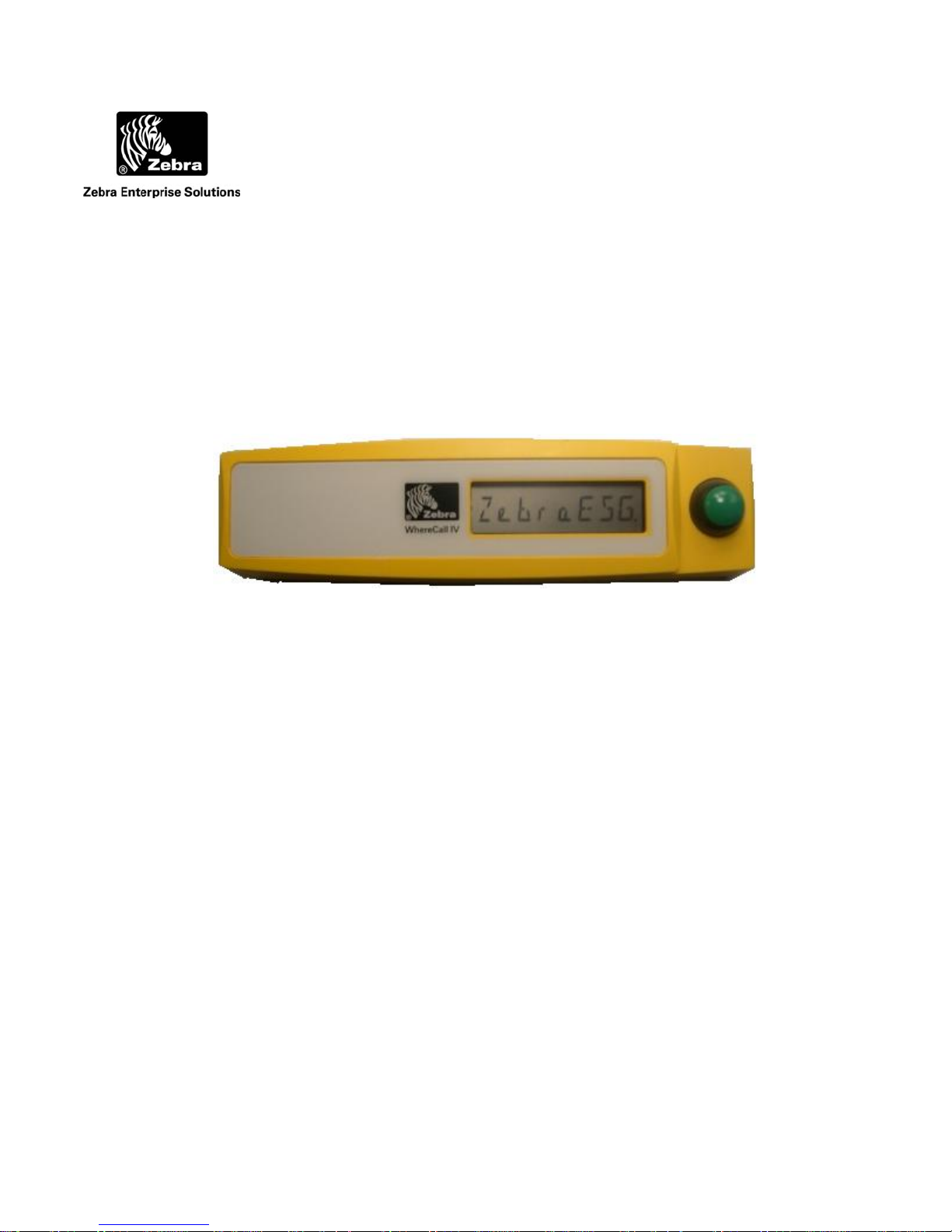
1 OVERVIEW
The Zebra Enterprise Solutions (ZES) WhereCall System allows users in manufacturing and
assembly operations to request service or specific parts without leaving their workstations.
Specific parts or service requests may be assigned to individual WhereCall IV devices so that
users may indicate which item is needed. For example, an assembly worker using several parts:
Each part is associated with a separate WhereCall IV device located in the workstation. By
pressing the green button on the WhereCall IV device, a radio signal is sent by the WhereCall
System to the computer system in the supply area, indicating which workstation requires the
specified part or service. The display will first blink CALL , and then alternate between CALL
and the time since the button press. This message can be customized to site preferences.
The WhereCall IV also operates in an optional SWITCH mode. This mode can be used to
indicate a status; the display will blink either -- ON -- or - OFF -- to indicate a functional status.
The status will toggle each time the button is pressed. These messages can also be customized
to site preferences. Each status can display a multi-word message on up to two different screen
buffers.
To insure that the WhereCall system is in constant operation, real-time monitoring using an “I’m
Still Alive” blinking transmission advises the system supervisor of the status of each WhereCall
IV device. Battery status is also included in these “I’m still alive” messages as well as in the
switch blinks, as well as in the button initiated blinks.
The WhereCall IV may be mounted in a work area with removable fasteners, double-sided foam
tape or with mounting brackets and screws (Refer to Section 2.1, Installation and Mounting).
___________________________________________________________________________ 7
TFF-2220-00AA and TFF-2221-00AA User’s Guide D1436 Rev B
©2008 Zebra Enterprise Solutions. WhereCall IV and all product names and numbers are Zebra Enterprise Solutions trademarks. All other trademarks are the property of their respective owners.
Page 8
___________________________________________________________________________
User Guide
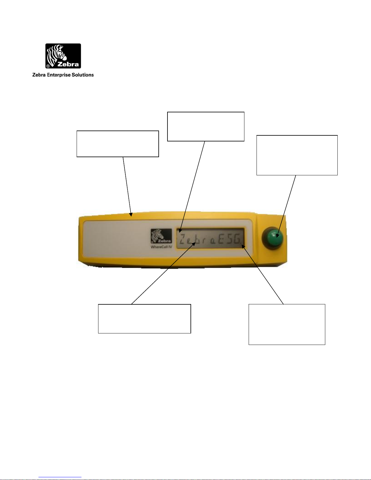
Flashing apostrophe
Durable high visibility
yellow plastic case
indicates CCX mode
is enabled
Large pushbutton to
activate WhereCall IV
blinks or to advance
through menu options
Easy to read 8-character,
14-segment LCD display
Flashing decimal
indicates ISO 24730
transmission
Figure 1: The WhereCall IV
___________________________________________________________________________ 8
TFF-2220-00AA and TFF-2221-00AA User’s Guide D1436 Rev B
©2008 Zebra Enterprise Solutions. WhereCall IV and all product names and numbers are Zebra Enterprise Solutions trademarks. All other trademarks are the property of their respective owners.
Page 9

___________________________________________________________________________
User Guide
2 COMPONENTS
2.1 ISO 24730 System
The WhereCall ISO 24730 System consists of four major components: the WhereCall IV
device; a location antenna; a location processor and a ZES computer server. This document
details only the WhereCall IV device.
The WhereCall IV is a palm-sized device approximately 6.3 inches by 1.7 inches, 1.2 inch thick,
in a yellow case. A green colored actuator button is on the right side of the device. A liquid
crystal display (LCD) screen is located next to the button, near the center of the device.
The ZES Location Sensor (LOS) or Locating Access Point (LAP) receives radio signals from
the WhereCall IV device when the work station user sends a call requesting parts by pressing the
green button on the WhereCall IV. These signals are transferred from the LOS/LAP by
Ethernet or wireless backhaul to the VSS server. A message is generated by the server and sent
to the user’s computer system indicating that a part is needed at workstation initiating the
replenishment request..
If necessary, a WhereWand hand-held programming device allows the ZES technician to
configure the WhereCall IV device for custom applications. The WhereWand is not required
for most applications.
___________________________________________________________________________ 9
TFF-2220-00AA and TFF-2221-00AA User’s Guide D1436 Rev B
©2008 Zebra Enterprise Solutions. WhereCall IV and all product names and numbers are Zebra Enterprise Solutions trademarks. All other trademarks are the property of their respective owners.
Page 10

___________________________________________________________________________
User Guide
2.1 CCX System
The CCX System consists of four major components: the WhereCall IV device; CCX access
points; a wireless LAN controller and a location processor. This document details only the
WhereCall IV device.
The WhereCall IV is a palm-sized device approximately 6.3 inches by 1.7 inches, 1.2 inch thick,
in a yellow case. A green colored actuator button is on the right side of the device. A liquid
crystal display (LCD) screen is located next to the button, near the center of the device.
The CCX access points receives radio signals from the WhereCall IV device when the work
station user sends a call requesting parts by pressing the green button on the WhereCall IV.
These signals are transferred by cable to the wireless LAN controller.
The wireless LAN controller converts signals from the antenna(s) and sends them to the
location processor. The location processor passes the message through a VSS bridge to the
VSS server which send an alert to the user’s computer system indicating that a part is needed at
the location of the WhereCall IV device.
If necessary, the WhereWand hand-held communicator allows the ZES technician to configure
the WhereCall IV device. The WhereWand is not required for most applications.
___________________________________________________________________________ 10
TFF-2220-00AA and TFF-2221-00AA User’s Guide D1436 Rev B
©2008 Zebra Enterprise Solutions. WhereCall IV and all product names and numbers are Zebra Enterprise Solutions trademarks. All other trademarks are the property of their respective owners.
Page 11
___________________________________________________________________________
User Guide
3 INSTALLATION & MOUNTING
The WhereCall IV may be mounted in a work area with removable fasteners, double-coated
foam tape, hanging brackets, or with mounting screws. . The WhereCall IV display is optimized
for viewing at an angle perpendicular from the operator or from above. Mounting the WhereCall
IV above an operator’s eyelevel does not provide maximum contrast for the LCD display.
Each WhereCall IV must be mounted in a location to provide an unobstructed view in at least
one direction. To maintain communication with the Location Antennas, do not install the
WhereCall IV inside a metal enclosure such as a metal cabinet.
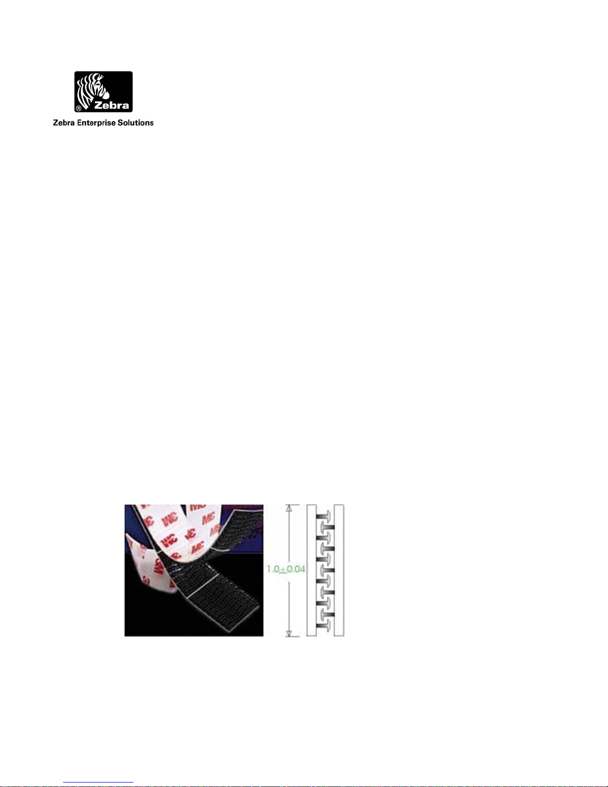
3.1 Poly-Lock
A plastic, adhesive-backed fastener, Poly-Lock uses mushroom-shaped contact points that
overlap and snap together, forming a strong attachment that can be separated by a forceful pull.
Poly-Lock is not included with the WhereCall IV, but is available from ZES in precut squares.
Contact your ZES account manager for information, reference part number TM-204-00.
Figure 2: Poly-Lock fastener with adhesive backing
___________________________________________________________________________ 11
TFF-2220-00AA and TFF-2221-00AA User’s Guide D1436 Rev B
©2008 Zebra Enterprise Solutions. WhereCall IV and all product names and numbers are Zebra Enterprise Solutions trademarks. All other trademarks are the property of their respective owners.
Page 12
___________________________________________________________________________
_
_
_
User Guide
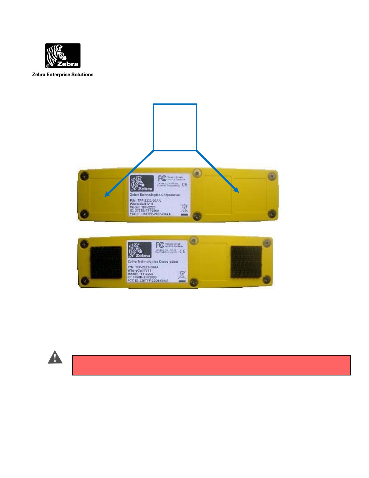
Apply the
Poly-Lock
squares to
these two
locations
Figure 3: Poly-Lock positions
_____
CAUTION
_________
3.2 Mounting WhereCall IV with Poly-Lock
_
Do not apply the poly-lock when the temperature is below 60°F (15°C) or above 90°F
(32°C).
1. Select the desired location in the workstation to mount the WhereCall IV.
2. Clean the mounting surface and the back cover of the WhereCall IV with isopropyl alcohol.
___________________________________________________________________________ 12
TFF-2220-00AA and TFF-2221-00AA User’s Guide D1436 Rev B
©2008 Zebra Enterprise Solutions. WhereCall IV and all product names and numbers are Zebra Enterprise Solutions trademarks. All other trademarks are the property of their respective owners.
Page 13
___________________________________________________________________________
_
User Guide
3. Select two pairs (they are shipped in attached pairs)of Poly-Lock squares, remove the
adhesive backing on one side of each pair, and then press them to the tag case, sticky side
down as shown in Figure 3.
4. You should now have two pairs of Poly-Lock attached to the back of the WhereCall IV.
Remove the adhesive backing from both squares.
5. While holding the WhereCall IV, gently press the unit against the mounting surface to assure
that the adhesive on the squares is bonded to the surface.
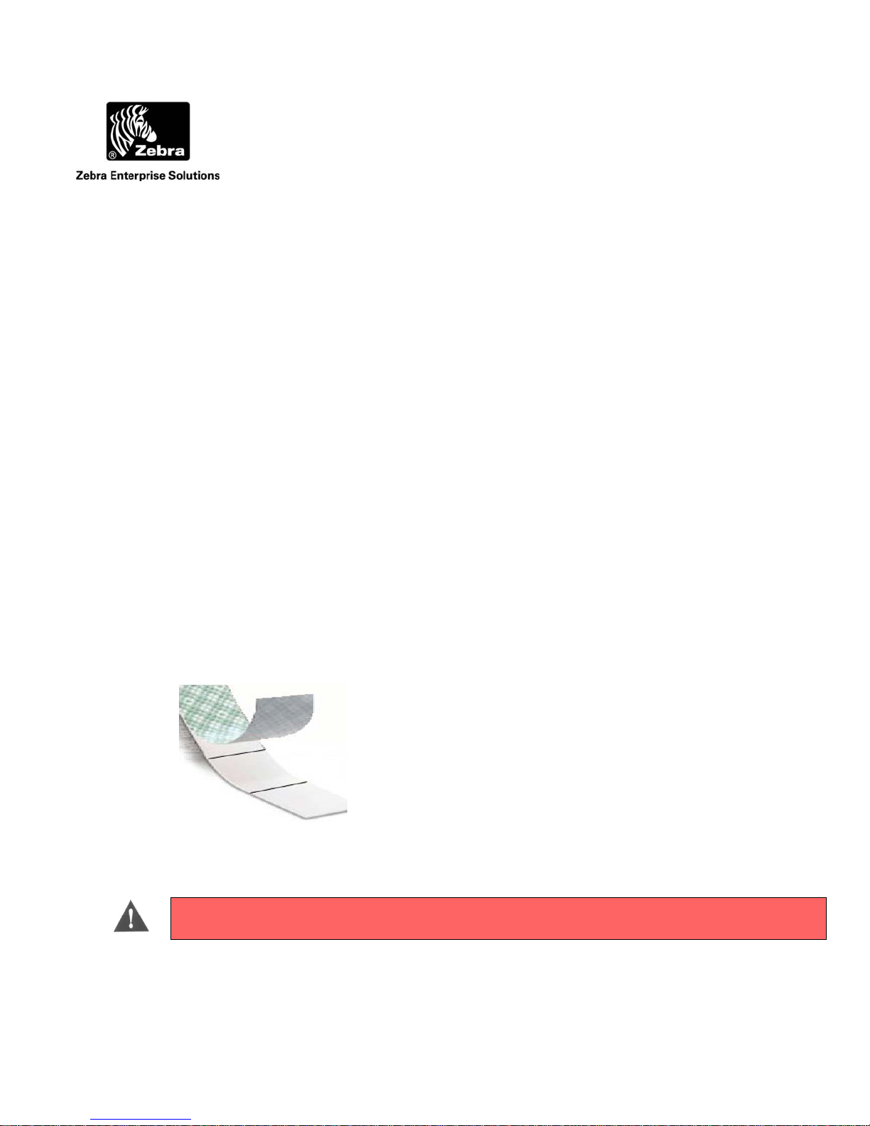
3.3 WhereTag Foam Tape Squares
WhereTag foam tape, both sides adhesive, provides a secure, semi-permanent mounting method
for the WhereCall IV device. Foam tape is not included with the WhereCall IV. Contact your
ZES Account Manager for information, reference part number TM-202-00.
Figure 4: Foam tape squares
________
The foam tape applies a layer of permanent adhesive film to both surfaces. Care should
be taken in the application of foam tape because once applied it is difficult to remove.
CAUTION
_________
___________________________________________________________________________ 13
TFF-2220-00AA and TFF-2221-00AA User’s Guide D1436 Rev B
©2008 Zebra Enterprise Solutions. WhereCall IV and all product names and numbers are Zebra Enterprise Solutions trademarks. All other trademarks are the property of their respective owners.
Page 14

___________________________________________________________________________
_
User Guide
Apply the
Foam Tape
squares to
these two
locations
Figure 5: Foam tape squares
3.4 Mounting WhereCall IV with Foam Tape Squares
_______
Do not apply the foam tape when the temperature is below 60°F (15°C) or above 90°F
CAUTION
________
___________________________________________________________________________ 14
TFF-2220-00AA and TFF-2221-00AA User’s Guide D1436 Rev B
©2008 Zebra Enterprise Solutions. WhereCall IV and all product names and numbers are Zebra Enterprise Solutions trademarks. All other trademarks are the property of their respective owners.
(32°C).
1. Select the desired location to mount the WhereCall IV.
2. Clean the mounting surface and the back plate of the WhereCall IV with isopropyl alcohol.
3. Select two foam tape squares, remove the adhesive backing from one side only and apply
them to the back cover of the WhereCall IV as shown in Figure 5.
Page 15

___________________________________________________________________________
User Guide
4. Remove the adhesive backing from the exposed surface of the tape squares.
5. While holding the WhereCall IV, aligned to the desired position. Gently press the unit onto
the mounting surface.
3.5 Cable Hanging Mounting Bracket
The WhereCall IV may also be installed from an overhead cable for ease of use in a workstation
where mounting on flat surfaces is unsafe or inconvenient. Hanging cable brackets are not
included with the WhereCall IV but are available from ZES. Contact your ZES Account
Manager for information, reference part number TM-241-00.
Figure 6: Cable Hanging Mounting Bracket
___________________________________________________________________________ 15
TFF-2220-00AA and TFF-2221-00AA User’s Guide D1436 Rev B
©2008 Zebra Enterprise Solutions. WhereCall IV and all product names and numbers are Zebra Enterprise Solutions trademarks. All other trademarks are the property of their respective owners.
Page 16

___________________________________________________________________________
User Guide
Remove and save these
4 screws
Figure 7: Attaching WhereCall IV to Mounting Bracket
3.6 Installing WhereCall IV with Cable Hanging Bracket
1. Using a 5/64 inch hex drive bit, remove 4 screws from the bottom cover as shown in
Figure 7.
2. Align the mounting bracket so the 4 screw holes align with the 4 screw holes in the
WhereCall IV bottom cover. Be sure the four counter sunk holes in the mounting
bracket are visible and not against the WhereCall IV bottom cover. Reinsert the screws
through the bracket and into the bottom cover of WhereCall IV, with torque set to
.6 inch-pounds [0.68 + 0.07 Newton-meters]. See figure 8.
6.0 +
3. Hang the mounting bracket in the desired location by threading the cable into the slot on
the end of the bracket.
___________________________________________________________________________ 16
TFF-2220-00AA and TFF-2221-00AA User’s Guide D1436 Rev B
©2008 Zebra Enterprise Solutions. WhereCall IV and all product names and numbers are Zebra Enterprise Solutions trademarks. All other trademarks are the property of their respective owners.
Page 17

___________________________________________________________________________
User Guide
Figure 8: Cable Hanging Bracket Installed
3.7 Screw Mounting Bracket
The WhereCall IV may be installed using screw by utilizing the screw mounting bracket. Screw
mounting brackets are not included with the WhereCall IV but are available from ZES. Contact
your ZES Account Manager for information, reference part number TM-240-00.
Figure 9: Screw Mounting Bracket
___________________________________________________________________________ 17
TFF-2220-00AA and TFF-2221-00AA User’s Guide D1436 Rev B
©2008 Zebra Enterprise Solutions. WhereCall IV and all product names and numbers are Zebra Enterprise Solutions trademarks. All other trademarks are the property of their respective owners.
Page 18

___________________________________________________________________________
User Guide
3.8 Installing WhereCall IV with Screw Mounting Bracket
1. Using a 5/64 inch hex drive bit, remove 4 screws from the bottom cover as shown in
Figure 7.
2. Align the mounting bracket so the 4 screw holes align with the 4 screw holes in the
WhereCall IV bottom cover. Be sure the four counter sunk holes in the mounting bracket
are visible and not against the WhereCall IV bottom cover. Reinsert the screws through the
bracket and into the bottom cover of WhereCall IV, with torque set to 6.0 + .6 inch-
pounds [0.68 + 0.07 Newton-meters]. See figure 10.
3. Attach mounting bracket in the desired location using two screws or rivets through the
counter sunk holes at the ends of the mounting bracket. The 0.188 inch [4.78 mm]
diameter holes are spaced 7.0 inches apart.
Figure 10: Screw Mounting Bracket Installed
___________________________________________________________________________ 18
TFF-2220-00AA and TFF-2221-00AA User’s Guide D1436 Rev B
©2008 Zebra Enterprise Solutions. WhereCall IV and all product names and numbers are Zebra Enterprise Solutions trademarks. All other trademarks are the property of their respective owners.
7.0 inch [177.8 mm]
Page 19

___________________________________________________________________________
User Guide
4 OPERATION OF THE WHERECALL IV
The WhereCall IV is a wireless messaging device that is capable of transmitting simple
messages to the ZES Infrastructure. These messages can range from a call for parts for line
side material replenishment to a request for supervisor assistance. There are three modes of
operation:
• Button or CALL Tag Mode
• Messaging or SWITCH Tag Mode
• OFF Mode
The WhereCall IV is shipped in the “OFF” mode. There is also a battery change mode that
is used to condition the tag to for installation of replacement batteries.
When the WhereCall IV is on the OFF mode, the display shows
PWR OFF . To turn the
WhereCall IV on when it is in the OFF mode, press the button once and the tag will resume
operation in either the CALL mode or the SWITCH mode depending on the mode it was in
when the OFF mode was selected.
___________________________________________________________________________ 19
TFF-2220-00AA and TFF-2221-00AA User’s Guide D1436 Rev B
©2008 Zebra Enterprise Solutions. WhereCall IV and all product names and numbers are Zebra Enterprise Solutions trademarks. All other trademarks are the property of their respective owners.
Page 20

___________________________________________________________________________
User Guide
4.1 Call Mode
In CALL mode the WhereCall IV can be used for parts call and other operations that do not
require an indication as to whether the request was fulfilled. In this mode, the operator
presses the button to send the request message, and the WhereCall IV will transmit blinks
with “Switch ID 0” which has status 2. The display on the WhereCall IV will flash CALL
for one minute and then start to count up in minutes since the call was made. This lets the
operator easily verify how long it has been since they made their request. The display is
capable of counting up to 9 days, 23 hours, and 59 minutes shown as 9d23h59m after which it
will continue to alternate between CALL and 9d23h59m but the elapsed time will not
increment any further.
The displayed CALL can be replaced with any other 8-character custom message. The
custom message will blink for one minute after each button push, and then the custom
message will alternate with the elapsed time.
___________________________________________________________________________ 20
TFF-2220-00AA and TFF-2221-00AA User’s Guide D1436 Rev B
©2008 Zebra Enterprise Solutions. WhereCall IV and all product names and numbers are Zebra Enterprise Solutions trademarks. All other trademarks are the property of their respective owners.
Page 21

___________________________________________________________________________
User Guide
4.2 Switch Mode
In switch mode, the display toggles between -- ON -- and -- OFF --. The normal starting state
is OFF. If the operator presses the button, then the WhereCall will send a message signaling
the change in state and the display will change to -- ON --. The resulting transmission blink
includes “Switch ID 0” which has status 2. The next button press will cause a new message
to be transmitted with “Switch ID 1” which has status 4. This signals the change of state and
the display will change back to - OFF --. In the SWITCH mode the WhereCall IV will send
multiple transmissions at increasing intervals after each button press. The first set of blinks
occurs as soon as the button is pressed, then repeats at 1 minute after the button press. The
message is then repeated at the following periods after the initial button press: 5 minutes, 10
minutes, 15 minutes, and then 30 minutes.. After completing that sequences, the WhereCall
IV then continue sending a set of blinks every 60 minutes.
The displayed -- ON -- and - OFF – messages can be replaced to show any one or a pair of 8-
character custom messages. If the message is replaced with a pair of custom messages, then
the display will not flash, but instead alternate between the pair of custom messages. When
the button is pressed, the display will alternate between the other pair of messages
___________________________________________________________________________ 21
TFF-2220-00AA and TFF-2221-00AA User’s Guide D1436 Rev B
©2008 Zebra Enterprise Solutions. WhereCall IV and all product names and numbers are Zebra Enterprise Solutions trademarks. All other trademarks are the property of their respective owners.
Page 22

___________________________________________________________________________
User Guide
4.3 Turning WhereCall IV Off
The WhereCall IV can be switched to the Power OFF mode from either CALL mode or
SWITCH mode. In order to do this, press and hold the button until the display shows
******** and then release the button. The display will show the tag firmware version TAG
2109 for a few seconds and then show the PIC Microcontroller firmware PIC 1017 version
for a few seconds, the show PWR OFF . Note that the displayed version number may differ
than those shown above. The WhereCall IV is now OFF and all transmissions are disabled.
The magnetic receiver in the tag is also disabled.
4.4 Switching WhereTag IV Modes
To change modes between CALL mode and Switch mode or visa versa, press and hold the
button. After about 5 seconds, the display will show ********. DO NOT release the button
while the display shows ********, but continue to keep the button depressed until the display
shows:
CALL ? if the WhereCall IV is currently in SWITCH mode
-
- SWITCH ? if the WhereCall IV is currently is CALL mode.
When either of these is displayed, release the button , and then press and release the button
again within five seconds. This will change the operational mode.
If the WhereCall IV has been changed from CALL mode to SWITCH mode, the tag will send
SW ID 1 with status 4 and the display will show - OFF --.
If the WhereCall IV has been changed from SWITCH mode to CALL mode, the tag will send
SW ID 0 with status 2 and the display will show CALL .
___________________________________________________________________________ 22
TFF-2220-00AA and TFF-2221-00AA User’s Guide D1436 Rev B
©2008 Zebra Enterprise Solutions. WhereCall IV and all product names and numbers are Zebra Enterprise Solutions trademarks. All other trademarks are the property of their respective owners.
Page 23

___________________________________________________________________________
User Guide
4.5 Changing System Protocols
To change the WhereCall IV mode between ISO 24730, CCX, and dual mode, the WhereCall IV
must be in OFF mode and display PWR OFF . Press and hold the button for several seconds
until the display starts to cycle between these options…ISO MODE, CCX MODE, DUALMODE,
and CNG BATT.
To switch to ISO 24730 mode, keep the button pressed until the display is showing ISO MODE,
then release the button, then click the button again to activate the mode. This mode will disable
all CCX blinks and the WhereCall IV will only send ISO 24730 blinks. In ISO 24730 mode, the
decimal point in the lower right most corner of the LCD will flash.
To switch to CCX mode, keep the button pressed until the display is showing CCX MODE, then
release the button, then click the button again to activate the mode. This mode will disable all
ISO 24730 blinks and the WhereCall IV will only send CCX blinks. In CCX mode, the
apostrophe in the upper left most corner of the LCD will flash.
To switch to dual protocol mode, keep the button pressed until the display is showing
DUALMODE, then release the button, then click the button again to activate the mode. In this
mode, the WhereCall IV send both ISO 24730 and CCX blinks. In dual protocol mode, both
the decimal in the lower right most corner and the apostrophe in the upper left most corner of
the LCD will flash.
If the user has inadvertently released the button at the wrong time and the WhereCall IV is
displaying the wrong mode, do not click the button again. The tag will timeout and return to
OFF mode and the display will show PWR OFF . The user can now start the changing protocol
sequence again.
___________________________________________________________________________ 23
TFF-2220-00AA and TFF-2221-00AA User’s Guide D1436 Rev B
©2008 Zebra Enterprise Solutions. WhereCall IV and all product names and numbers are Zebra Enterprise Solutions trademarks. All other trademarks are the property of their respective owners.
Page 24

___________________________________________________________________________
User Guide
4.6 WhereCall IV Soft Messages
The WhereCall IV supports soft messaging which allows the user to replace the displayed
messages CALL , --—ON -- and/or -—OFF -- with custom messages. Setting or changing the
soft message will require a WhereWand to enter and program the messages to the WhereCall IV
magnetically.
If a custom message is configured in CALL mode, then the custom message will be displayed. ,
instead of CALL blinking or alternating with elapsed time, There is no change to the air
protocol blink content .
In SWITCH mode, each of the two messages can be replaced with a single message or a pair of
messages.
If custom messages are configured and the WhereCall IV is in the SWITCH mode ON state,
instead of --—ON -- blinking, the display will either blink the custom ON mode single message
or alternate between the pair of custom ON mode messages.
If custom messages are configured and the WhereCall IV is in the SWITCH mode OFF state,
instead of -—OFF -- blinking, the display will blink either the custom OFF mode single message
or alternate between the pair of custom OFF mode messages.
___________________________________________________________________________ 24
TFF-2220-00AA and TFF-2221-00AA User’s Guide D1436 Rev B
©2008 Zebra Enterprise Solutions. WhereCall IV and all product names and numbers are Zebra Enterprise Solutions trademarks. All other trademarks are the property of their respective owners.
Page 25

___________________________________________________________________________
User Guide
4.7 Changing the WhereCall IV Batteries
____________
CAUTION
____________
Caution: Personnel changing batteries must use an ESD wrist strap to prevent damage of the
tag circuit board due to static discharge. Follow the manufacturer’s instructions for proper use
of the static prevention device.
4.7.1 Description
WhereCall IV Tags have a nominal battery life of 5 years. After that nominal battery life, it is
possible to replace the batteries to extend the life of the tag itself; however, ZES does not
provide personnel or Services for this process.
To avoid damaging the WhereCall IV tags, the proper screwdrivers with the correct torque
settings must be used. This procedure must be followed or the WhereCall IV may become non-
operational. There is no field recovery method if this event occurs. Batteries should be replaced
before they are completely dead.
ZES assumes no responsibility for damage to or failure of the WhereCall Tags resulting
from this battery replacement procedure.
4.7.2 Materials
Qty. 2 per tag 3.6V Lithium battery
NOTE: Use only the exact battery and manufacturer specified above.
___________________________________________________________________________ 25
TFF-2220-00AA and TFF-2221-00AA User’s Guide D1436 Rev B
©2008 Zebra Enterprise Solutions. WhereCall IV and all product names and numbers are Zebra Enterprise Solutions trademarks. All other trademarks are the property of their respective owners.
(ZES P/N 20057, SAFT P/N LS 14500).
SAFT address - 12 rue Sadi Carnot 93170 BAGNOLET - France
Tel.: +33 (0)1 49 93 19 18 Fax: +33 (0)1 49 93 19 50
Page 26

___________________________________________________________________________
User Guide
4.7.3 Tools
ZES does not provide the required materials and tools for changing batteries with the WhereCall
IV Tags. The following tools will be required to change the WhereCall IV batteries.
• One, torque wrench with a 5/64 inch hex drive bit and the torque set to 6.0 + .6 inch-
pounds [0.68 +
0.07 Newton-meters] for the six screws on the bottom cover of the tag.
• One, “small, pocket size” flat blade screw driver use to remove batteries from the battery
holder.
• One, ESD wrist strap or equivalent static protection device.
4.7.4 Procedure
To change the WhereCall IV batteries, the WhereCall IV must be in OFF mode and display
PWR OFF . See section 4.3 for instructions on turning the WhereCall IV off.
Step 1: Enter battery change mode as follows
Press and hold the button for several seconds until the display starts to cycle between
these options…ISO MODE, CCX MODE, DUALMODE, and CNG BATT. Release the
button when the display shows CNG BATT, then click the button again to activate the
mode. The WhereCall IV is now in a mode that draws more current in bursts to ensure
the circuitry fully discharges when the batteries are removed. This mode will expire in 5
minutes, so the batteries should be replaced within 5 minutes to ensure proper restart of
the internal processors.
Step 2: Remove the 6 screws from the bottom cover of the WhereCall IV and remove the
bottom cover and sealing gasket.
___________________________________________________________________________ 26
TFF-2220-00AA and TFF-2221-00AA User’s Guide D1436 Rev B
©2008 Zebra Enterprise Solutions. WhereCall IV and all product names and numbers are Zebra Enterprise Solutions trademarks. All other trademarks are the property of their respective owners.
Page 27

___________________________________________________________________________
_
User Guide
Step 3: Remove both of the old batteries and dispose of properly.
Step 4: Install two new batteries, being careful to orient the batteries correctly and not to install
either battery backwards. Refer to figure 11 for proper battery orientation.
Note battery orientation. The arrows
point to the + side of the 2 batteries
Figure 11: Battery Replacement
________
Caution: Inserting a battery with the wrong orientation may damage the tag. ZES assumes no
CAUTION
_________
responsibility for damage to or failure of the WhereCall Tags resulting from this battery
replacement procedure.
Step 5: Reattach the sealing gasket and the bottom cover with the 6 screws, and torque screws
to 6.0 + .6 inch-pounds [0.68 + 0.07 Newton-meters].
___________________________________________________________________________ 27
TFF-2220-00AA and TFF-2221-00AA User’s Guide D1436 Rev B
©2008 Zebra Enterprise Solutions. WhereCall IV and all product names and numbers are Zebra Enterprise Solutions trademarks. All other trademarks are the property of their respective owners.
Page 28

___________________________________________________________________________
(
(
g
)
(
(
g)
(
g
)
(
g
)
(
g
)
(
g
)
User Guide
5 WHERECALL IV LCD DISPLAY MESSAGES
Display
Message
“CALL ”
flashing)
CustCall
flashin
“CALL ”
10h 42m
(alternating)
CustCall
10h 42m
Display Meaning Comments Action required
CALL mode button blinks are
being transmitted.
This display follows the Call”
display and indicates the
elapsed time from the last
button press.
This mode will continue for 60
seconds following a button press.
The time advances from
1m until it reaches
9d23h59m then holds until the
button is pressed again.
None
None
(alternating)
--“ON --
flashing)
Cust ON1
flashin
Cust ON1
Cust ON2
alternatin
- “OFF --
flashin
CustOFF1
flashin
CustOFF1
CustOFF2
alternatin
********
SWITCH mode where the tag
will transmit Switch ID 0 with
tag status 2.
SWITCH mode where the tag
will transmit Switch ID 0 with
tag status 4.
Indicates that the user has held
the button for several seconds
and the unit will turn off when
released
In SWITCH mode, each button
press will toggle between
-- ON -- and - OFF --.
In SWITCH mode, each button
press will toggle between
-- ON -- and - OFF --.
After the button is release, the
unit will display its firmware
versions before turning off.
None
None
Release the button
to turn the
WhereCall IV off.
Pressing the button will turn the
PWR OFF
Indicates that the WhereCall
IV is in PWR OFF mode
unit on again into the mode
(CALL or SWITCH) that the
unit was in prior to being turned
None
off.
___________________________________________________________________________ 28
TFF-2220-00AA and TFF-2221-00AA User’s Guide D1436 Rev B
©2008 Zebra Enterprise Solutions. WhereCall IV and all product names and numbers are Zebra Enterprise Solutions trademarks. All other trademarks are the property of their respective owners.
Page 29

___________________________________________________________________________
User Guide
Display
Message
CALL ?
SWITCH ?
ISO MODE
CCX MODE
DUALMOD
E
CNG BATT
(cycling)
CCX MODE
DUALMOD
E
CNG BATT
ISO MODE
(cycling)
Display Meaning Comments Action required
To change modes release the
button and then press the button
Indicates that the user has held
the button for several seconds
and can now change mode
from SWITCH mode to CALL
mode if desired.
again within 5 seconds. Pressing
the button again will initiate
CALL mode and issue Call
blinks. Releasing the button
without pressing it again will
Release the button,
then press the
button again to
initiate “CALL”
operation.
cause the WhereCall IV to enter
OFF mode.
To change modes release the
button and then press the button
Indicates that the user has held
the button for several seconds
and can now change mode
from CALL mode to SWITCH
mode if desired.
again within 5 seconds. Pressing
the button again will initiate
SWITCH mode and issue Switch
ID 0 blinks. Releasing the button
without pressing it again will
Release the button,
then press the
button again to
initiate “SWITCH”
operation.
cause the WhereCall IV to enter
OFF mode.
ISO MODE indicates the user
has pressed and held the
button for several seconds
while in PWR OFF state and
can now put the tag into ISO
24730 transmit mode
CCX MODE indicates the user
has pressed and held the
button for several seconds
while in PWR OFF state and
can now put the tag into an
unsupported mode
The display will cycle between
the various protocol modes and
the change battery mode. The
user must release the button
when the 24730 mode is shown
then click the button again to
activate the mode.
The display will cycle between
the various protocol modes and
the change battery mode. The
user must release the button
when the desire mode is shown
then click the button again to
activate the mode.
Release the button,
then press the
button again to turn
the WhereCall IV
on in ISO 24730
mode.
Release the button,
then wait until the
WhereCall IV
returns to POWER
OFF mode
___________________________________________________________________________ 29
TFF-2220-00AA and TFF-2221-00AA User’s Guide D1436 Rev B
©2008 Zebra Enterprise Solutions. WhereCall IV and all product names and numbers are Zebra Enterprise Solutions trademarks. All other trademarks are the property of their respective owners.
Page 30

___________________________________________________________________________
g
User Guide
Display
Messa
DUALMOD
E
CNG BATT
ISO MODE
CCX MODE
e
(cycling)
CNG BATT
ISO MODE
CCX MODE
DUALMOD
E
(cycling)
CHANGE
BATTERY
(alternating)
LOW BATT
(alternating)
Display Meaning Comments Action required
DUALMODE indicates the user
has pressed and held the
button for several seconds
while in PWR OFF state and
can now put the tag into an
unsupported mode
CNG BATT indicates the user
has pressed and held the
button for several seconds
while in PWR OFF state and
can now put the tag into
battery change mode
The display will cycle between
the various protocol modes and
the change battery mode. The
user must release the button
when the desire mode is shown
then click the button again to
activate the mode.
The display will cycle between
the various protocol modes and
the change battery mode. The
user must release the button
when CNG BATT is shown then
click the button again to activate
the mode.
Release the button,
then wait until the
WhereCall IV
returns to POWER
OFF mode.
Release the button,
then press the
button again to put
the WhereCall IV
into battery change
mode.
The user should remove the
Indicates that the WhereCall
IV is in battery change mode.
bottom cover and replace the
batteries within 5 minutes of
starting the mode. To exit the
Replace batteries or
click the button to
exit the mode.
mode, click the button again.
Indicates that the WhereCall
IV has detected a low battery.
The user should enter battery
change mode and change the
batteries.
This message will alternate or
cycle with the existing messages
in either CALL or SWITCH
mode.
Enter battery
change mode and
replace the
batteries.
___________________________________________________________________________ 30
TFF-2220-00AA and TFF-2221-00AA User’s Guide D1436 Rev B
©2008 Zebra Enterprise Solutions. WhereCall IV and all product names and numbers are Zebra Enterprise Solutions trademarks. All other trademarks are the property of their respective owners.
Page 31

___________________________________________________________________________
User Guide
6 SPECIFICATIONS: WHERECALL IV DEVICE
Specifications are subject to change without notice.
Mechanical
Dimensions 6.45 x 1.74 x 1.27 inches [163.8 x 44.2 x 32.3 mm] nominal
Weight 6.3 ounces [180 grams] nominal
Color High Visibility Yellow and Light Gray
Attachments Mounting Brackets, Poly-Lock, or Foam Tape
Form Factor Wall Mounted-Rugged Aesthetics
Durability
Drop 4 feet [1.22 meters] to concrete
Temperature
+0°F to +130°F, [ -20° to +55°C ] Operating
-10°F to +140°F, [ -25° to +65°C ] Storage
Humidity 0% to 95% condensing
Dust and Water
Resistant
IP54 per IEC 60529 (dust and water spray tight)
Button Functional for 1 million cycles
ESD
Battery
Battery Type Two “AA” Lithium Thionyl Chloride Cells
Battery Life Typical 5 years (Batteries are customer replaceable)
___________________________________________________________________________ 31
TFF-2220-00AA and TFF-2221-00AA User’s Guide D1436 Rev B
©2008 Zebra Enterprise Solutions. WhereCall IV and all product names and numbers are Zebra Enterprise Solutions trademarks. All other trademarks are the property of their respective owners.
Functional per IEC-1000-4-2 Level 4
Operation not disrupted up to 8kV
Unit not permanently damaged up to 15kV
Page 32

___________________________________________________________________________
User Guide
Connector (used with WhereCall IV PLC)
Mating Connector Waterproof, 4 pin, mates with Turck RS-4.41T-X (where X is the
cable length) or equivalent
Display Characteristics
Number of
8
Characers
Format 14-Segment with apostrophe and decimal for each character
Function Check previous page
Digit Size .28 inch [7 mm] high
Back Lit No
Status Word
Length 4 bits
Battery low bit Bit 0 (---l)
0 = battery is OK
l = low battery
CALL mode
Button Push or
SWITCH mode =
Bit 1 (--1-)
0 = blink is not a switch blink, but a keep alive blink
1 = blink is CALL blink or SWITCH = ON blink
“ON” state
SWITCH mode =
“OFF” state
Bit 2 (-1--)
0 = blink is not a switch blink, but a keep alive blink
1 = blink is SWITCH = OFF blink
___________________________________________________________________________ 32
TFF-2220-00AA and TFF-2221-00AA User’s Guide D1436 Rev B
©2008 Zebra Enterprise Solutions. WhereCall IV and all product names and numbers are Zebra Enterprise Solutions trademarks. All other trademarks are the property of their respective owners.
Page 33

___________________________________________________________________________
User Guide
7 CONFIGURABLE PARAMETERS
The WhereCall IV is configured with a default configuration suitable for most applications
during the manufacturing process. If desired, the WhereCall IV can be reconfigured using a
WhereWand. The following table identifies the configurable parameters. Valid ranges for each
parameter are determined by the WhereWand.
Configurable ISO 24730 Parameters
Parameter Group Parameter Factory Defaults
Interval 1 hour
Keep Alive Blinks
Long Message Blinks
WherePort Blinks
Switch Blinks
Alternate Interval OFF
Alternate Duration OFF
Sub-blinks 4
Interval OFF
Alternate Interval OFF
Alternate Duration OFF
Message Mask 0001 (only message 1 enabled)
Sub-blinks 4
Number of Blinks 0 (no blinks)
Interval 10 seconds
Retrigger Time 10 seconds
Retrigger Mode sL
Sub-blinks 4
Number of Blinks 3
Interval 5 seconds
Retrigger Time 1 second
Misc RF TX Power 12 dBm
___________________________________________________________________________ 33
TFF-2220-00AA and TFF-2221-00AA User’s Guide D1436 Rev B
©2008 Zebra Enterprise Solutions. WhereCall IV and all product names and numbers are Zebra Enterprise Solutions trademarks. All other trademarks are the property of their respective owners.
Sub-blinks 8
Page 34

___________________________________________________________________________
User Guide
8 WHERECALL IV PLC
WhereCall IV PLC User & Interface Guide
___________________________________________________________________________ 34
TFF-2220-00AA and TFF-2221-00AA User’s Guide D1436 Rev B
©2008 Zebra Enterprise Solutions. WhereCall IV and all product names and numbers are Zebra Enterprise Solutions trademarks. All other trademarks are the property of their respective owners.
Page 35

___________________________________________________________________________
User Guide
8.1 WhereCall IV PLC FCC Requirements
This device must operate in compliance with Federal Communications Commission (FCC)
Rules and Regulations Parts 15. See FCC registration label, located on the bottom of the
equipment, for the FCC registration.
This equipment has been tested and found to comply with the limits for both Class A and Class
B devices, pursuant to Part 15 of the FCC Rules.
This device complies with FCC ID: Approval TBD
This ISM device complies with Canadian ICES-001
Cet appareil ISM est conforme à la norme pendant du Canada.
Radio Type Approval No………Approval TBD
RF Notice
Any changes or modifications to ZES equipment not expressly approved by ZES could void the
user’s authority to operate the equipment.
___________________________________________________________________________ 35
TFF-2220-00AA and TFF-2221-00AA User’s Guide D1436 Rev B
©2008 Zebra Enterprise Solutions. WhereCall IV and all product names and numbers are Zebra Enterprise Solutions trademarks. All other trademarks are the property of their respective owners.
Page 36

___________________________________________________________________________
User Guide
8.2 WhereCall IV PLC Overview
This document describes how to mount and interface the WhereCall IV PLC to your equipment
via the external industrial connector.
The WhereCall IV PLC is a variation of the standard WhereCall IV. It allows the call tag to be
used with a remote switch in external equipment. The external equipment can “press the
button” to initiate a call. This enables the WhereCall IV PLC and the user equipment to operate
unattended and to send a call message via the ZES system.
For more information regarding the operation and installation of the
WhereCall IV PLC please refer to the WhereCall IV User Guide.
In this document the Terms WhereCall IV PLC and TFF-2221 are used interchangeably
and will have the same meaning.
___________________________________________________________________________ 36
TFF-2220-00AA and TFF-2221-00AA User’s Guide D1436 Rev B
©2008 Zebra Enterprise Solutions. WhereCall IV and all product names and numbers are Zebra Enterprise Solutions trademarks. All other trademarks are the property of their respective owners.
Page 37

___________________________________________________________________________
User Guide
8.3 WhereCall IV PLC Installation & Mounting
The WhereCall IV PLC may be mounted in a work area with removable fasteners, double-
coated foam tape, hanging brackets.
Each WhereCall IV PLC must be mounted in a location to provide an unobstructed view to a
location antenna in at least one direction. To maintain communication with the Location
Antennas, do not install the WhereCall IV PLC inside a metal enclosure such as a metal cabinet.
____________
Note
____________
In selecting the mounting location keep in mind that the cable from the equipment to the
WhereCall IV PLC must not exceed 3 meters (10 feet).
___________________________________________________________________________ 37
TFF-2220-00AA and TFF-2221-00AA User’s Guide D1436 Rev B
©2008 Zebra Enterprise Solutions. WhereCall IV and all product names and numbers are Zebra Enterprise Solutions trademarks. All other trademarks are the property of their respective owners.
Page 38

___________________________________________________________________________
User Guide
8.4 Connecting the WhereCall IV PLC
The WhereCall IV PLC can be connected to a remotely mounted switch that is used to initiate a
“button blink”. This product works very much like the WhereCall IV except that “button”
actuation is provided from another device.
8.4.1 WhereCall IV PLC Cable and Connector.
The TFF-2221 is to be connected using a Turck, RS 4.41T-X cord-set. The length of the cable
is limited to 3.0M (10 feet). When this cord set is used the connection will be watertight.
This cord-set can be purchased from:
Turck USA
3000 Campus Drive
Minneapolis, MN 55441
1-800-588-8725
WWW.TURCK.COM
Other Turck locations are listed on the web site.
_________
___________
____________
Note
The cable length between the TFF-2221 and the remote device must not
exceed 3.0 Meters (10 feet).
ZES does not supply the cord sets and connectors for the WhereCall IV PLC.
___________________________________________________________________________ 38
TFF-2220-00AA and TFF-2221-00AA User’s Guide D1436 Rev B
©2008 Zebra Enterprise Solutions. WhereCall IV and all product names and numbers are Zebra Enterprise Solutions trademarks. All other trademarks are the property of their respective owners.
Page 39

___________________________________________________________________________
User Guide
8.4.2 WhereCall IV PLC Electrical Connection.
Pins one (1) and three (3) are to be connected to the remote switch.
The external switch is connected across pins 1 and 3 as
indicated
Figure 12: WhereCall IV PLC Connector
____________
Note
Use the reference detail on the connector to identify the pin numbers. The
connector may not be oriented the same on all units.
___________________________________________________________________________ 39
TFF-2220-00AA and TFF-2221-00AA User’s Guide D1436 Rev B
©2008 Zebra Enterprise Solutions. WhereCall IV and all product names and numbers are Zebra Enterprise Solutions trademarks. All other trademarks are the property of their respective owners.
Page 40

___________________________________________________________________________
User Guide
WhereTag IV PLC Interface Cable Electrical Block Diagram
The momentary switch will initiate blinks
when it is closed for 100 milliseconds and
then released. The switch must not
remain closed for more than 3.0 seconds
to avoid switching to power off mode.
____________
Turck RS 4.41T-X
(Connect to WhereCall IV PLC)
The cable should be connected and routed to prevent large voltage spikes and static
_______________
CAUTION
discharges from being carried into the tag via the switch cable. This may result in false
“Button Calls” being generated or in extreme cases the TFF-2221 could be damaged.
Figure 13: WhereCall IV PLC Electrical Interface
___________________________________________________________________________ 40
TFF-2220-00AA and TFF-2221-00AA User’s Guide D1436 Rev B
©2008 Zebra Enterprise Solutions. WhereCall IV and all product names and numbers are Zebra Enterprise Solutions trademarks. All other trademarks are the property of their respective owners.
Page 41

___________________________________________________________________________
User Guide
8.4.3 WhereCall IV PLC Switch Operation
The switch used to operate the TFF-2221 must be a momentary type. The TFF-2221 will
initiate a “Button Blink” sequence when the switch breaks after having been closed for at least
100ms and less than 5 s. It the switch is closed for less than 100 ms the unit will not react. See
Table 1 for more information.
____________
Note
____________
If the switch remains closed for three (3 seconds or more the unit will change to the “OFF”
mode.
___________________________________________________________________________ 41
TFF-2220-00AA and TFF-2221-00AA User’s Guide D1436 Rev B
©2008 Zebra Enterprise Solutions. WhereCall IV and all product names and numbers are Zebra Enterprise Solutions trademarks. All other trademarks are the property of their respective owners.
 Loading...