

Page 1
TC8300
Touch Computer
Integrator Guide
for Android ™ 8.1 Oreo
MN-003403-03 Rev A
Page 2

Copyright
ZEBRA and the stylized Zebra head are trademarks of Zebra Technologies Corporation, registered in many
jurisdictions worldwide. Google, Android, Google Play and other marks are trademarks of Google LLC; Oreo is
a trademark of Mondelez International, Inc. group. All other trademarks are the property of their respective
owners. ©2019 Zebra Technologies Corporation and/or its affiliates. All rights reserved.
COPYRIGHTS & TRADEMARKS: For complete copyright and trademark information, go to
www.zebra.com/copyright
.
WARRANTY: For complete warranty information, go to www.zebra.com/warranty
END USER LICENSE AGREEMENT: For complete EULA information, go to www.zebra.com/eula
Terms of Use
• Proprietary Statement
This manual contains proprietary information of Zebra Technologies Corporation and its subsidiaries
(“Zebra Technologies”). It is intended solely for the information and use of parties operating and maintaining
the equipment described herein. Such proprietary information may not be used, reproduced, or disclosed to
any other parties for any other purpose without the express, written permission of Zebra Technologies.
• Product Improvements
Continuous improvement of products is a policy of Zebra Technologies. All specifications and designs are
subject to change without notice.
• Liability Disclaimer
Zebra Technologies takes steps to ensure that its published Engineering specifications and manuals are
correct; however, errors do occur. Zebra Technologies reserves the right to correct any such errors and
disclaims liability resulting therefrom.
• Limitation of Liability
In no event shall Zebra Technologies or anyone else involved in the creation, production, or delivery of the
accompanying product (including hardware and software) be liable for any damages whatsoever (including,
without limitation, consequential damages including loss of business profits, business interruption, or loss of
business information) arising out of the use of, the results of use of, or inability to use such product, even if
Zebra Technologies has been advised of the possibility of such damages. Some jurisdictions do not allow
the exclusion or limitation of incidental or consequential damages, so the above limitation or exclusion may
not apply to you.
.
.
Revision History
Changes to the original guide are listed below:
Change Date Description
-01 Rev A 04/2019 Initial release.
-02 Rev A 09/2019 Updated to include the DPM configuration, DPM accessories, and SE4770-SR.
-03 Rev A 11/2019 Updated the Decode Range distances.
2
Page 3

Table of Contents
Copyright ......................................................................................................................... 2
Terms of Use ..................................................................................................................2
Revision History ..............................................................................................................2
About This Guide........................................................................................................ 11
Introduction ................................................................................................................... 11
Configurations ............................................................................................................... 11
Software Versions ......................................................................................................... 13
Notational Conventions ................................................................................................. 13
Service Information ....................................................................................................... 14
Getting Started............................................................................................................ 16
Introduction ................................................................................................................... 16
Unpacking ............................................................................................................. 16
Removing the Screen Protection Film ................................................................... 16
Features ........................................................................................................................ 17
Setup ............................................................................................................................. 19
Installing the microSD Card ................................................................................... 19
Installing the Battery .............................................................................................. 22
Charging the Battery ............................................................................................. 23
Powering on the Device ................................................................................................ 24
Resetting the TC8300 ................................................................................................... 25
Performing a Soft Reset ........................................................................................ 25
Performing a Hard Reset ....................................................................................... 25
Performing an Enterprise Reset ............................................................................ 26
Performing a Factory Reset .................................................................................. 26
Accessories................................................................................................................. 28
Introduction ................................................................................................................... 28
3
Page 4

Table of Contents
2-Slot USB Charge Cradle ............................................................................................ 30
Setup ..................................................................................................................... 32
Charging the Device .............................................................................................. 33
Charging the Spare Battery ................................................................................... 34
Battery Charging ................................................................................................... 34
Main Battery Charging .................................................................................... 34
Spare Battery Charging .................................................................................. 34
Charging Temperature .......................................................................................... 34
5-Slot Charge Only Cradle ............................................................................................ 34
Setup ..................................................................................................................... 35
Charging the Device .............................................................................................. 35
Battery Charging ................................................................................................... 36
Main Battery Charging .................................................................................... 36
Charging Temperature .................................................................................... 36
5-Slot Charge Only Cradle with Battery Charger .......................................................... 36
Setup ..................................................................................................................... 37
Charging the Device .............................................................................................. 37
Battery Charging ................................................................................................... 38
Main Battery Charging .................................................................................... 38
Spare Battery Charging .................................................................................. 38
Charging Temperature .................................................................................... 38
5-Slot Ethernet Cradle .................................................................................................. 39
Charging the Device .............................................................................................. 40
Battery Charging ................................................................................................... 41
Main Battery Charging .................................................................................... 41
Charging Temperature .................................................................................... 41
Daisy-chaining Ethernet Cradles ........................................................................... 41
Ethernet Settings ................................................................................................... 42
Configuring for a Proxy Server .............................................................................. 42
Configuring Ethernet Static IP Address ................................................................. 43
LED Indicators ....................................................................................................... 44
Establishing Ethernet Connection ......................................................................... 44
5-Slot Ethernet Cradle with Battery Charger ................................................................. 45
Setup ..................................................................................................................... 46
Charging the Device .............................................................................................. 46
Battery Charging ................................................................................................... 47
Main Battery Charging .................................................................................... 47
Spare Battery Charging .................................................................................. 47
Charging Temperature .................................................................................... 47
Daisy-chaining Ethernet Cradles ........................................................................... 48
Ethernet Settings ................................................................................................... 48
Establishing Ethernet Connection ......................................................................... 48
4-Slot Battery Charger .................................................................................................. 48
4
Page 5

Table of Contents
Setup ..................................................................................................................... 49
Charging Spare Batteries ................................................................................ 49
Charging Temperature .................................................................................... 50
2-Slot Desk Bracket ...................................................................................................... 50
Assembly ............................................................................................................... 50
Mounting Cradle .................................................................................................... 51
5-Slot Desktop Bracket ................................................................................................. 52
Assembly ............................................................................................................... 52
Mount Cradle ......................................................................................................... 53
Cart Mount ....................................................................................................................54
Installation ............................................................................................................. 55
5-Slot Cradle Rack Installation ...................................................................................... 56
4-Slot Battery Chargers Rack Installation ..................................................................... 60
Rack Mount Installation ................................................................................................. 63
5-Slot Cradle Wall Installation ....................................................................................... 66
Bottom Tray Assembly .......................................................................................... 66
Bracket Wall Mounting .......................................................................................... 66
4-Slot Battery Charger Wall Installation ........................................................................ 69
Bottom Tray Assembly .......................................................................................... 69
Bracket Wall Mounting .......................................................................................... 69
Condensation Resistant Rear Bezel Replacement ....................................................... 71
USB Communication .................................................................................................. 75
Introduction ................................................................................................................... 75
Transferring Files with a Host Computer via USB ........................................................ 75
Transferring Files ................................................................................................. 75
Connecting to the TC8300 as a Media Device ...................................................... 76
Connecting to the TC8300 as a Camera ............................................................... 76
Disconnect from the Host Computer ............................................................................. 76
DataWedge .................................................................................................................. 77
Introduction ................................................................................................................... 77
Accessing DataWedge .................................................................................................. 77
Basic Scanning ............................................................................................................. 77
Profiles .......................................................................................................................... 77
Profile0 .......................................................................................................................... 78
Plug-ins ......................................................................................................................... 78
Input Plug-ins ........................................................................................................ 78
Process Plug-ins ................................................................................................... 78
Output Plug-ins ...................................................................................................... 79
5
Page 6

Table of Contents
Profiles Screen .............................................................................................................. 79
Profile Context Menu .................................................................................................... 79
Options Menu ........................................................................................................ 80
Disabling DataWedge ............................................................................................ 80
Creating a New Profile .................................................................................................. 80
Profile Configuration ..................................................................................................... 81
Associating Applications ........................................................................................ 82
Data Capture Plus ................................................................................................. 83
Barcode Input ................................................................................................................ 85
Enabled ........................................................................................................... 85
Scanner Selection ........................................................................................... 85
Hardware Trigger ............................................................................................ 86
Auto Switch to Default on Event ..................................................................... 86
Configure Scanner Settings ............................................................................ 86
Select Scanner to Set Parameters .................................................................. 87
Decoders ......................................................................................................... 87
Decoder Params ............................................................................................. 90
UPC EAN Params ........................................................................................... 95
Reader Params ............................................................................................... 98
Scan Params ................................................................................................ 101
UDI Params .................................................................................................. 102
Multibarcode params .................................................................................... 103
Keep enabled on suspend ............................................................................ 103
Voice Input .......................................................................................................... 103
Keystroke Output ................................................................................................. 104
Intent Output ........................................................................................................ 105
Intent Overview ................................................................................................... 106
IP Output ............................................................................................................. 107
Usage ............................................................................................................ 108
Using IP Output with IPWedge ............................................................................ 108
Using IP Output without IPWedge ................................................................ 109
Generating Advanced Data Formatting Rules .............................................. 111
Configuring ADF Plug-in ...................................................................................... 111
Creating a Rule ................................................................................................... 111
Defining a Rule ............................................................................................. 112
Defining Criteria ............................................................................................ 112
Defining an Action ......................................................................................... 114
Deleting a Rule ............................................................................................. 114
Order Rules List ............................................................................................ 115
Deleting an Action ......................................................................................... 116
ADF Example ................................................................................................ 116
DataWedge Settings ................................................................................................... 119
Importing a Configuration File ....................................................................... 120
Exporting a Configuration File ....................................................................... 120
Importing a Profile File ........................................................................................ 120
6
Page 7

Table of Contents
Exporting a Profile ............................................................................................... 121
Restoring DataWedge ......................................................................................... 121
Configuration and Profile File Management ................................................................ 121
Enterprise Folder ........................................................................................................ 121
Auto Import .......................................................................................................... 122
Reporting ............................................................................................................. 122
Programming Notes ............................................................................................ 122
Overriding Trigger Key in an Application ............................................................. 122
Capture Data and Taking a Photo in the Same Application ................................ 122
Disable DataWedge on Device and Mass Deploy ............................................... 123
DataWedge APIs ................................................................................................. 123
Soft Scan Trigger ................................................................................................ 123
Function Prototype ........................................................................................ 123
Parameters ................................................................................................... 123
Scanner Input Plugin ........................................................................................... 123
Function Prototype ........................................................................................ 124
Parameters ................................................................................................... 124
Return Values ............................................................................................... 124
Example ........................................................................................................ 125
Comments ..................................................................................................... 125
Enumerate Scanners ........................................................................................... 125
Function Prototype ........................................................................................ 125
Parameters ................................................................................................... 125
Return Values ............................................................................................... 126
Example ........................................................................................................ 127
Comments ..................................................................................................... 127
Set Default Profile ............................................................................................... 128
Default Profile Recap .................................................................................... 128
Usage Scenario ............................................................................................ 128
Function Prototype ........................................................................................ 128
Parameters ................................................................................................... 128
Return Values ............................................................................................... 128
Example ........................................................................................................ 129
Comments ..................................................................................................... 129
Reset Default Profile ........................................................................................... 129
Function Prototype ........................................................................................ 130
Parameters ................................................................................................... 130
Return Values ............................................................................................... 130
Example ........................................................................................................ 130
Comments ..................................................................................................... 130
Switch To Profile ................................................................................................. 131
Profiles Recap ............................................................................................... 131
Usage Scenario ............................................................................................ 131
Function Prototype ........................................................................................ 131
Parameters ................................................................................................... 131
7
Page 8

Table of Contents
Return Values ............................................................................................... 132
Example ........................................................................................................ 132
Comments ..................................................................................................... 132
Notes ............................................................................................................. 133
Settings...................................................................................................................... 134
Introduction ................................................................................................................. 134
Setting Screen Lock .................................................................................................... 134
Setting Screen Lock Using PIN ........................................................................... 135
Setting Screen Unlock Using Password .............................................................. 135
Setting Screen Unlock Using Pattern .................................................................. 136
Showing Passwords ............................................................................................ 137
Language Usage ......................................................................................................... 137
Changing the Language Setting .......................................................................... 137
Adding Words to the Dictionary ........................................................................... 138
Keyboard Settings ............................................................................................... 138
Button Remapping ............................................................................................... 138
Remapping a Button ............................................................................................ 138
PTT Express Configuration ......................................................................................... 139
Importing a PTT Express Configuration File ....................................................... 139
RxLogger .................................................................................................................... 139
RxLogger Settings ............................................................................................... 140
RxLogger Configuration ...................................................................................... 140
ANR Module ........................................................................................................ 141
Kernal Module ..................................................................................................... 141
Logcat Module ..................................................................................................... 142
LTS Module ......................................................................................................... 143
Ramoops Module ................................................................................................ 143
Qxdm Module ...................................................................................................... 143
Resource Module ................................................................................................ 144
Snapshot Module ................................................................................................ 144
TCPDump Module ............................................................................................... 145
Tombstone Module .............................................................................................. 145
Configuration File ................................................................................................ 145
Enabling Logging ................................................................................................. 145
Disabling Logging ................................................................................................ 146
Extracting Log Files ............................................................................................. 146
RxLogger Utility .......................................................................................................... 147
App View ............................................................................................................. 147
Viewing Logs ................................................................................................. 147
Backup ................................................................................................................ 149
8
Page 9

Table of Contents
Archive Data ................................................................................................. 149
Overlay View ....................................................................................................... 149
Initiating the Main Chat Head ........................................................................ 150
Removing the Main Chat Head ..................................................................... 150
Viewing Logs ................................................................................................. 150
Removing a Sub Chat Head Icon ................................................................. 151
Backing Up In Overlay View ......................................................................... 151
About Phone ............................................................................................................... 151
Application Deployment........................................................................................... 153
Introduction ................................................................................................................. 153
Security ....................................................................................................................... 153
Secure Certificates ...................................................................................................... 153
Installing a Secure Certificate ..................................................................................... 153
Configuring Credential Storage Settings ............................................................. 154
Development Tools ..................................................................................................... 154
Android ................................................................................................................ 154
GMS Restricted ........................................................................................................... 155
ADB USB Setup .......................................................................................................... 155
Application Installation ................................................................................................ 155
Installing Applications Using the USB Connection ...................................................... 156
Installing Applications Using the Android Debug Bridge ..................................... 157
Installing Applications Using a microSD Card ..................................................... 158
Uninstalling an Application .................................................................................. 159
System Update .................................................................................................... 160
Storage ....................................................................................................................... 161
Random Access Memory .................................................................................... 162
External Storage .................................................................................................. 162
Internal Storage ................................................................................................... 163
Enterprise Folder ................................................................................................. 164
App Management ........................................................................................................ 164
Viewing App Details .................................................................................................... 165
Managing Downloads ................................................................................................. 166
Maintenance and Troubleshooting ........................................................................ 167
Introduction ................................................................................................................. 167
Maintaining the Device ................................................................................................ 167
Battery Safety Guidelines ........................................................................................... 167
Long Term Storage ..................................................................................................... 168
Cleaning Instructions .................................................................................................. 168
Approved Cleanser Active Ingredients ................................................................ 168
9
Page 10

Table of Contents
Harmful Ingredients ............................................................................................. 168
Device Cleaning Instructions ............................................................................... 169
Special Cleaning Notes ....................................................................................... 169
Cleaning Materials Required ............................................................................... 169
Cleaning Frequency ............................................................................................ 169
Cleaning the Device ............................................................................................ 169
Housing ......................................................................................................... 169
Display .......................................................................................................... 170
Exit Window .................................................................................................. 170
Cleaning Battery Connectors .............................................................................. 170
Cleaning Cradle Connectors ............................................................................... 170
Troubleshooting .......................................................................................................... 171
TC8300 ................................................................................................................ 171
Cradles ................................................................................................................ 172
Specifications............................................................................................................ 173
Technical Specifications ............................................................................................. 173
TC8300 ................................................................................................................ 173
SE965 Standard Range Laser Decode Zones .................................................... 176
SE4750-MR Decode Zones ................................................................................ 177
SE4750-DP Decode Zones ................................................................................. 178
SE4750-DPW Decode Zones .............................................................................. 179
SE4770-SR Decode Zones ................................................................................. 180
SE4850 Decode Zones ....................................................................................... 181
I/O Connector Pin-Outs ....................................................................................... 182
2-Slot USB Charge Cradle Technical Specifications ........................................... 183
2-Slot DPM USB Charge Cradle Technical Specifications .................................. 184
5-Slot Charge Only Cradle Technical Specifications ........................................... 184
5-Slot Charge Only Cradle with Battery Charger Technical Specifications ......... 185
5-Slot Ethernet Cradle Technical Specifications ................................................. 185
5-Slot Ethernet Cradle with Battery Charger Technical Specifications ............... 186
4-Slot Battery Charger Technical Specifications ................................................. 186
USB and Charging Cable Technical Specifications ............................................ 187
Quick Disconnect Audio Cable Technical Specifications .................................... 187
3.5 mm Audio Cable Technical Specifications .................................................... 187
Index
10
Page 11

About This Guide
Introduction
This guide provides information about using the device and accessories.
NOTE
:
Screens and windows pictured in this guide are samples and can differ from actual screens.
Configurations
The TC8300 includes standard, condensation resistant, and premium configurations.
Table 1 Configurations
Radios Data Capture Memory OS Sensors
Configuration
NFC
Bluetooth 5.0
802.11 a/b/g/n/ac
Base
TC83B0-A005A510NA x x x x x x x x x x
TC83B0-2005A510NA x x x x x x x x x x
TC83B0-3005A510NA x x x x x x x x x x
TC83B0-6005A510NA x x x x x x x x x x
TC83B0-A005A510RW x x x x x x x x x x
TC83B0-2005A510RW x x x x x x x x x x
TC83B0-3005A510RW x x x x x x x x x x
TC83B0-6005A510RW x x x x x x x x x x
TC83B0-2005A510CN x x x x x x x x x x
TC83B0-3005A510CN x x x x x x x x x x
TC83B0-6005A510CN x x x x x x x x x x
TC83B0-2005A510IN x x x x x x x x x x
TC83B0-3005A510IN x x x x x x x x x x
TC83B0-6005A510IN x x x x x x x x x x
Condensation Resistant
TC83B0-2005A61CNA x x x x x x x x x x x
TC83B0-3005A61CNA x x x x x x x x x x x
TC83B0-6005A61CNA x x x x x x x x x x x
TC83B0-2005A61CRW x x x x x x x x x x x
SE965 Laser Engine
SE4750-MR Imager
SE4750-DP Imager
SE4750-DPA Imager
SE4770-SR Imager
SE4850 Imager
13 MP Camera
4” WVGA Color
4G RAM/32 GB Flash
V8.1.0
AndroidGMS
8G RAM/128 GB Flash
Accelerometer
Gyroscope
Proximity Sensor
Apps
Vibration
ATTE
Magnet
Scan
Touchscreen
11
Page 12

About This Guide
Table 1 Configurations
Magnet
Apps
Vibration
ATTE
Touchscreen
Radios Data Capture Memory OS Sensors
Configuration
NFC
Bluetooth 5.0
802.11 a/b/g/n/ac
SE965 Laser Engine
SE4750-MR Imager
SE4750-DP Imager
SE4770-SR Imager
SE4750-DPA Imager
SE4850 Imager
13 MP Camera
4” WVGA Color
4G RAM/32 GB Flash
V8.1.0
AndroidGMS
8G RAM/128 GB Flash
Accelerometer
Gyroscope
Proximity Sensor
TC83B0-3005A61CRW x x x x x x x x x x x
TC83B0-6005A61CRW x x x x x x x x x x x
TC83B0-2005A61CCN x x x x x x x x x x x
TC83B0-3005A61CCN x x x x x x x x x x x
TC83B0-2005A61CIN x x x x x x x x x x x
TC83B0-3005A61CIN x x x x x x x x x x x
Package 1
TC83BH-2205A710NA x x x x x x x xxxxxx xx
TC83BH-3205A710NA x x x xxxx xxxxxx xx
TC83BH-6205A710NA x x x x x x x xxxxxx xx
TC83BH-2205A710RW x x x x x x x xxxxxx xx
TC83BH-3205A710RW x x x xxxx xxxxxx xx
TC83BH-6205A710RW x x x x x x x xxxxxx xx
TC83BH-2205A710CN x x x x x x x xxxxxx xx
TC83BH-3205A710CN x x x xxxx xxxxxx xx
TC83BH-2205A710IN x x x x x x x xxxxxx xx
TC83BH-3205A710IN x x x xxxx xxxxxx xx
Package 2 High Memory
TC83BH-2206A710NA x x x x x x xxxxxxx xx
TC83BH-3206A710NA x x x x x x xxxxxxx xx
TC83BH-6206A710NA x x x x x x xxxxxxx xx
TC83BH-6206A710RW x x x x x x xxxxxxx xx
TC83BH-2206A710RW x x x x x x xxxxxxx xx
TC83BH-3206A710RW x x x x x x xxxxxxx xx
DPM
TC83B0-4005A610NA x x x x x x x x x x x
TC83B0-4005A610RW x x x x x x x x x x x
TC83B0-4005A610CN x x x x x x x x x x x
TC83B0-5005A610NA x x x x x x x x x x x
TC83B0-5005A610RW x x x x x x x x x x x
TC83B0-5005A610CN x x x x x x x x x x x
TC83B0-4005A610IN x x x x x x x x x x x
TC83B0-5005A610IN x x x x x x x x x x x
TAA
TC83B0-2005A510TA x x x x x x x x x x
TC83B0-3005A510TA x x x x x x x x x x
TC83B0-6005A510TA x x x x x x x x x x
TC83BH-6205A710TA x x x x x x x xxxxxx xx
TC83BH-2205A710TA x x x x x x x xxxxxx xx
TC83BH-3205A710TA x x x xxxx xxxxxx xx
Scan
12
Page 13

Software Versions
To determine the current software versions:
1. Swipe down from the Status bar to open the Quick Settings bar.
2. Touch > System.
3. Touch About phone.
4. Scroll to view the following information:
•Status
• Battery information
• SW components
• Legal information
•Model
• Android version
• Android security patch level
•Kernel version
• Build Fingerprint
• Build number.
About This Guide
To determine the device serial number, touch About phone > Status.
• Serial number
Chapter Descriptions
Topics covered in this guide are as follows:
• Getting Started, provides information on getting the mobile computer up and running for the first time.
• Accessories, describes the accessories available for the mobile computer and how to use the accessories
with the mobile computer.
• USB Communication,
• DataWedge, describes how to use and configure the DataWedge application.
• Settings, provides the settings for configuring the TC8300.
• Application Deployment, provides information for developing and managing applications.
• Maintenance and Troubleshooting, includes instructions on cleaning and storing the mobile computer, and
provides troubleshooting solutions for potential problems during TC8300 operation.
• Specifications, includes a table listing the technical specifications for the TC8300.
explains how to perform Bluetooth functionality on the mobile computer.
Notational Conventions
The following conventions are used in this document:
13
Page 14

About This Guide
• Bold text is used to highlight the following:
• Dialog box, window and screen names
• Drop-down list and list box names
• Check box and radio button names
• Icons on a screen
• Key names on a keypad
• Button names on a screen.
• Bullets (•) indicate:
• Action items
• Lists of alternatives
• Lists of required steps that are not necessarily sequential.
• Sequential lists (for example, those that describe step-by-step procedures) appear as numbered lists.
Related Documents and Software
The following documents provide more information about the TC8300.
• TC8300 Quick Start Guide, p/n MN-003365-xx
• TC8300 Regulatory Guide, p/n MN-003364-xx
• TC8300 Accessory Regulatory Guide, p/n MN002282Axx
• TC8300 User Guide for Android Version 8.1, p/n MN-003402-xx
• Rack/Wall Mount Bracket Installation Guide, p/n MN002412Axx
• Desk Mount Installation Guide, p/n MN002413Axx
• Hand Strap Installation Guide, p/n MN002417Axx
For the latest version of this guide and all guides, go to: http://www.zebra.com/support
Service Information
If you have a problem with your equipment, contact Customer Support for your region. Contact information is
available at: www.zebra.com/support
When contacting support, please have the following information available:
• Serial number of the unit (found on manufacturing label)
• Model number or product name (found on manufacturing label)
• Software type and version number
Customer Support responds to calls by email or telephone within the time limits set forth in support
agreements.
.
.
If the problem cannot be solved by Customer Support, you may need to return the equipment for servicing and
will be given specific directions. We are not responsible for any damages incurred during shipment if the
approved shipping container is not used. Shipping the units improperly can possibly void the warranty.
Remove the microSD card from the device before shipping for service.
If the device was purchased from a business partner, contact that business partner for support.
14
Page 15

About This Guide
Provide Documentation Feedback
If you have comments, questions, or suggestions about this guide, send an email to
EVM-Techdocs@zebra.com
.
15
Page 16

Getting Started
Introduction
This chapter describes the features of the TC8300 and explains how to install and charge the battery and how
to reset the TC8300.
Unpacking
Carefully remove all protective material from the TC8300 and save the shipping container for later storage and
shipping.
Verify that box contains all the equipment listed below:
• TC8300
• Battery
• Regulatory Guide.
Inspect the equipment for damage. If you are missing any equipment or if you find any damaged equipment,
contact Support immediately. See Service Information on page 14 for contact information.
Removing the Screen Protection Film
A screen protection film is applied to the TC8300 screen to protect the screen during shipping. To remove the
screen protector, carefully lift the thin film off the display.
16
Page 17
Features
5
7
4
9
1
3
8
6
2
121110
7
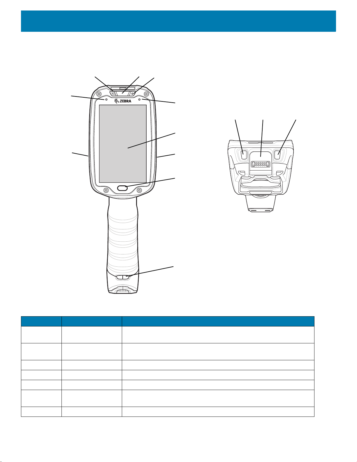
Figure 1 Front View
Getting Started
Table 1 Front View Descriptions
Number Item Function
1 Charging/Scan LED Indicates battery charging status while charging, good decode indication
during data capture and application generated notifications.
2 Power Button Turns the display on and off. Press and hold to reset the device and
power off.
3 Blue Indication LED User programmable LED.
4 Display Displays all information needed to operate the TC8300.
5 Touch Button Press to select items.
6 Hand Strap
Use for installing the optional hand strap.
Mounting Point
7 Speakers Provides audio output for video and music playback.
17
Page 18
Getting Started
1
2
4
5
7
8
9
6
3
3
8
10
4
3
3
8
8
5
7
6
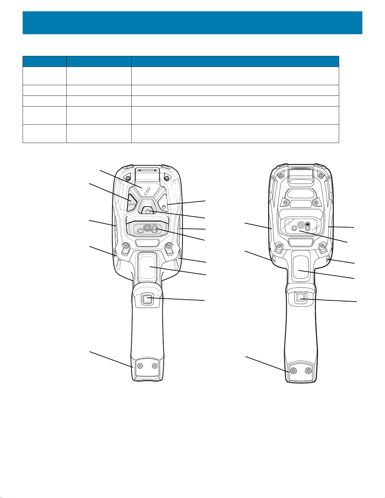
Standard DPM
Table 1 Front View Descriptions (Continued)
Number Item Function
8 Ambient Light
Sensor
9 Microphone Use for communication in Headset mode.
10 Volume Up Button Increases audio volume (programmable).
11 Interface Connector Provides USB host and client communication, audio and device charging
12 Volume Down
Button
Figure 2 Back View
Determines ambient light for controlling display backlight intensity
(optional).
via cables and accessories.
Decreases audio volume (programmable).
18
Page 19

Getting Started
Table 2 Back View Descriptions
Number Item Function
1 Camera Flash Provides illumination for the camera (optional).
2 Camera Takes photos and videos (optional).
3 Speaker Provides audio output.
4 Scanner Provides data capture using the imager or laser scanner.
5 Trigger Initiates data capture (programmable).
6 Push-To-Talk (PTT)
Button
7 Battery Pack Provides power to the device.
8 Hand Strap Mounting
Point
9 Proximity Sensor Long range proximity sensor (optional).
Initiates Push-To-Talk communication (programmable).
Use for installing the optional hand strap.
Setup
Perform these procedures to start using the TC8300 for the first time.
1. Install a micro secure digital (SD) card (optional).
2. Install the battery.
3. Charge the TC8300.
4. Power on the TC8300.
Installing the microSD Card
The microSD card slot provides secondary non-volatile storage. The slot is located under the back bezel of the
unit. Refer to the documentation provided with the card for more information, and follow the manufacturer's
recommendations for use.
WARNING
precautions include, but are not limited to, working on an ESD mat and ensuring that the operator is properly grounded.
Remove back bezel only in a dry location.
NOTE
When installing a microSD card on Condensation Resistant configurations, replace the Back Bezel with desiccant pack. See
Condensation Resistant Rear Bezel Replacement on page 71
absorbs ambient moisture and can lessen the life of the desiccant pack.
:
Follow proper electrostatic discharge (ESD) precautions to avoid damaging the microSD card. Proper ESD
:
The Condensation Resistant configuration has six screws securing the back bezel.
. Once the Rear Bezel is removed, the desiccant pack
1. Remove the Torx T8 screws holding the back bezel in place.
19
Page 20
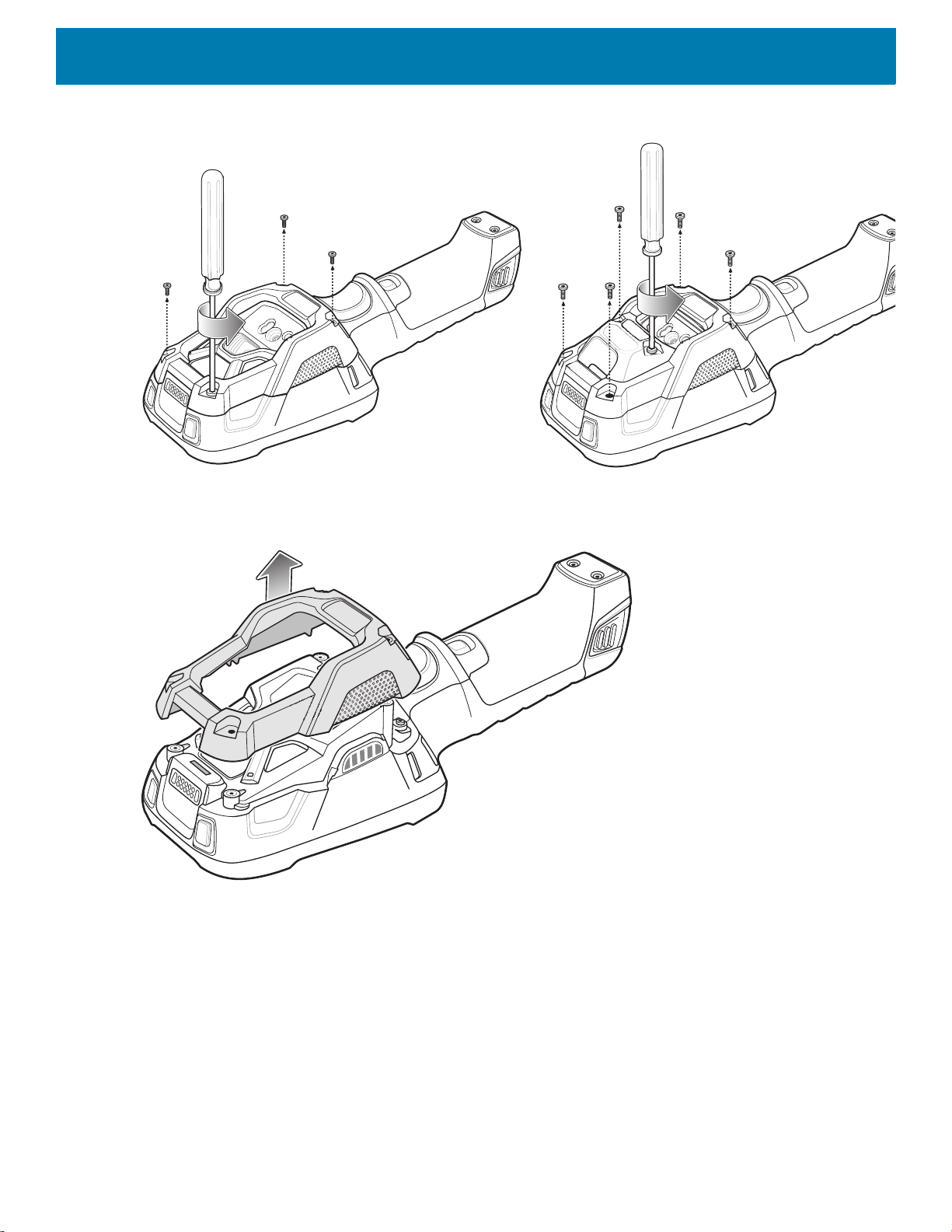
Figure 3 Remove Screws
2. Lift the bezel to expose the SD slot.
Getting Started
Figure 4 Remove Bezel
3. Insert the microSD card into the slot with contacts facing the bottom of the device.
20
Page 21

Figure 5 Insert microSD Card
5. Align the back bezel onto the device.
Getting Started
Figure 6 Align Back Bezel
4. Tighten the four screws using T8 hex screwdriver.
5. Torque to 4.5 kg-cm.
21
Page 22
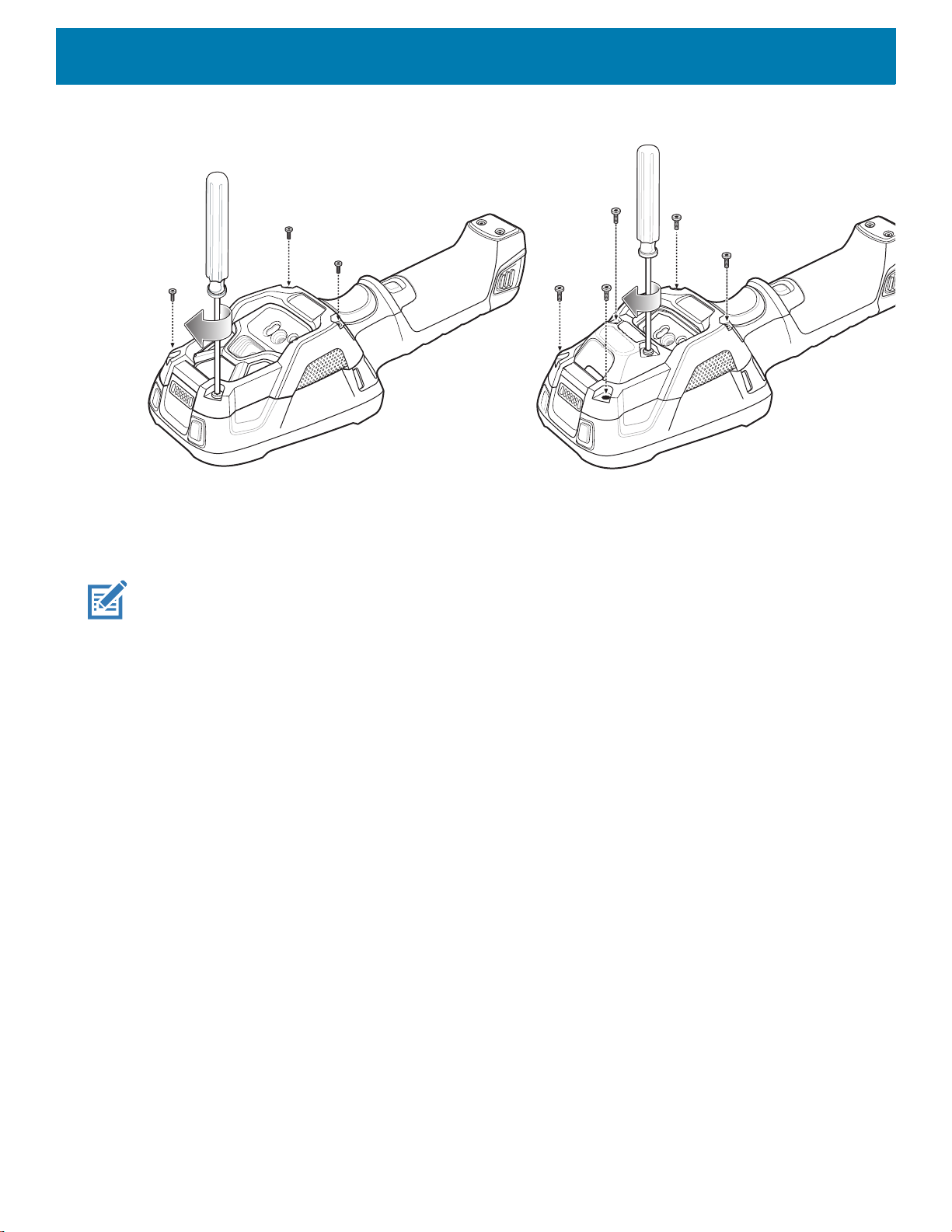
Figure 7 Secure Bezel
Getting Started
Installing the Battery
To install the battery:
NOTE
:
The battery is keyed to ensure that the battery is inserted properly. The notch in the battery must face the back of
the device.
1. Align the battery with the notch facing the back of the device.
2. Slide the battery into the handle of the device.
22
Page 23
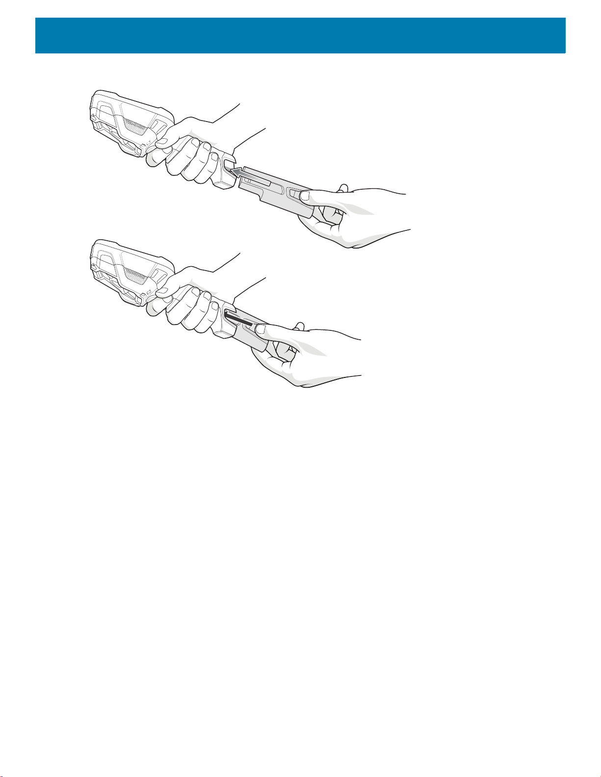
Figure 8 Battery Installation
Getting Started
3. Snap battery into place.
Charging the Battery
Before using the TC8300 for the first time, charge the battery using a cable or a cradle with the appropriate
power supply. For information about the accessories available for the TC8300, see Accessories.
The TC8300 is equipped with a supercapacitor (supercap) which automatically charges from the fully-charged
main battery. The supercap requires approximately 10 minutes to fully charge. The supercap retains random
access memory (RAM) data in memory and WLAN connection for at least 30 seconds when the main battery is
removed during Hot Swap. After 30 seconds, the WLAN connection is dropped and the RAM data is retained
for 20 minutes.
• 4-Slot Battery Charger
• 2-Slot USB Charge Cradle
• 5-Slot Charge Only Cradle
• 5-Slot Ethernet Cradle
• 5-Slot Charge Only Cradle with 4-Slot Battery Charger
• 5-Slot Charge Only Cradle with 4-Slot Battery Charger.
The 6,700 mAh battery charges from 0 - 90% in less than four hours at room temperature.
The 7,000 mAh battery charges from 0 - 90% in less than five hours at room temperature.
Charge batteries in temperatures from 0 °C to 40 °C (32 °F to 104 °F). The device or accessory always
performs battery charging in a safe and intelligent manner. At higher temperatures (e.g. approximately +37 °C
23
Page 24

Getting Started
(+98 °F)) the device or accessory may for small periods of time alternately enable and disable battery charging
to keep the battery at acceptable temperatures. The device or accessory indicates when charging is disabled
due to abnormal temperatures via its LED.
1. To charge the main battery, connect the charging accessory to the appropriate power source.
2. Insert the TC8300 into a cradle or attach to a cable. The device turns on and begins charging. The
Charging/Notification LED blinks amber while charging, then turns solid green when fully charged.
Table 3 Charging/Scan LED Charging Indicators
State Indication
Off TC8300 is not charging. TC8300 is not inserted correctly in the cradle or
connected to a power source. Charger/cradle is not powered.
Solid Amber Healthy battery is charging.
Solid Green Healthy battery charging is complete.
Fast Blinking Red
(2 blinks/second)
Solid Red Unhealthy battery is charging or fully charged.
IMPORTANT
battery power to turn on. You will need to charge the battery or replace it.
:
.When trying to power on the device, a quick blink of the charging LED indicates that it does not have enough
Charging error, e.g.:
- Temperature is too low or too high.
- Charging has gone on too long without completion (typically eight hours).
Powering on the Device
The device starts automatically as soon as power is applied; either with a charged battery installed or when
inserted into the cradle.
If a charged battery is installed and the device is turned off, press the Power button to turn on.
When the device is powered on for the first time, it initializes its system. The splash
period of time.
Figure 9 Splash Screen
screen appears for a short
24
Page 25

Getting Started
GMS AOSP
The splash screen is followed by the boot animation screen and then the Home Screen.
Figure 10 Home Screen
Resetting the TC8300
There are four reset functions:
• Soft reset
• Hard reset
• Enterprise reset
• Factory reset.
Performing a Soft Reset
Perform a soft reset if applications stop responding.
1. Press the power button until the menu appears.
2. Touch Restart.
3. The device reboots.
Performing a Hard Reset
CAUTION
:
Perform a hard reset only if the TC8300 stops responding.
To perform a hard reset, simultaneously press and hold the power button, trigger and PTT button for five
seconds. When the device reboots, release the buttons and trigger.
25
Page 26

Performing an Enterprise Reset
An Enterprise Reset erases all data in the /cache and /data partitions and clears all device settings, except
those in the /enterprise partition.
Before performing an Enterprise Reset, copy all applications and the key remap configuration file that you want
to persist after the reset into the /enterprise/usr/persist folder.
1. Download the Enterprise Reset file from the Zebra Support & Downloads web site.
2. Copy the Enterprise Reset zip file to the root of the microSD card. See USB Communication.
3. Press and hold the Power button until the menu appears.
4. Touch Power off.
The device turns off.
5. Press and release the Power button. Then press and hold the Power button and the Scan trigger.
6. When the Zebra splash screen appears, release the button and trigger.
The System Recovery Screen appears.
Getting Started
Figure 11 System Recovery Screen
7. Press the Up and Down Volume buttons to navigate to the apply update from SD card option.
8. Press the Power button.
9. Press the Up and Down Volume buttons to navigate to the Enterprise Reset zip file.
10.Press the Power button.
The Enterprise Reset occurs and then the device resets.
Performing a Factory Reset
A Factory Reset erases all data in the /cache, /data and /enterprise partitions in internal storage and
clears all device settings. A Factory Reset returns the device to the last installed operating system image. To
revert to a previous operating system version, re-install that operating system image. See System Update on
page 160 for more information.
1. Download the Factory Reset file from the Zebra Support & Downloads web site.
2. Copy the Factory Reset zip file to the root of the microSD card. See USB Communication.
3. Press and hold the Power button until the menu appears.
4. Touch Power off.
The device turns off.
26
Page 27

Getting Started
5. Press and release the Power button. Then press and hold the Power button and the Scan trigger.
6. When the Zebra splash screen appears, release the button and trigger.
The System Recovery Screen appears.
Figure 12 System Recovery Screen
7. Press the Up and Down volume buttons to navigate to the apply update from SD card option.
8. Press the Power button.
9. Press the Up and Down Volume buttons to navigate to the Factory Reset zip file.
10.Press the Power button.
The Factory Reset occurs and then the device resets.
27
Page 28

Accessories
Introduction
The TC8300 accessories provide a variety of product support capabilities.
Table 4 Accessories
Accessory Part Number Description
Cradles
2-Slot USB Charge
Cradle
2-Slot USB Charge
Cradle (for DPM only)
5-Slot Charge Only
Cradle
5-Slot Ethernet Cradle CRD-TC8X-5SETH-01 Provides device charging and provides Ethernet
5-Slot Charge Only
Cradle with Battery
Charger
5-Slot Ethernet Cradle
with Battery Charger
CRD-TC8X-2SUCHG-01 Provides device and spare battery charging and USB
communication with a host computer. Use with power
supply, p/n PWR-BGA12V50W0WW and country
specific grounded AC line cord.
CRD-TC8D-2SUCHG-01 Provides device and spare battery charging and USB
communication with a host computer. Use with power
supply, p/n PWR-BGA12V50W0WW and country
specific grounded AC line cord.
CRD-TC8X-5SCHG-01 Charges up to five devices. Use with power supply, p/n
PWR-BGA12V108W0WW, DC line cord, p/n
50-16002-029R and country specific grounded AC line
cord.
communication for up to five devices. Use with power
supply, p/n PWR-BGA12V108W0WW, DC line cord,
p/n 50-16002-029R and country specific grounded AC
line cord.
CRD-TC8X-5SC4BC-01 Charges up to four devices and four spare batteries.
Use with power supply, p/n PWR-BGA12V108W0WW,
DC line cord, p/n 50-16002-029R and country specific
grounded AC line cord.
CRD-TC8X-5SE4BC-01 Provides device charging and provides Ethernet
communication for up to four devices. Provides
charging for four spare batteries. Use with power
supply, p/n PWR-BGA12V108W0WW, DC line cord,
p/n 50-16002-029R and country specific grounded AC
line cord.
28
Page 29

Accessories
Table 4 Accessories (Continued)
Accessory Part Number Description
Batteries and Chargers
Battery BTRY-TC8X-67MA1-01
BTRY-TC8X-67MA1-10
BTRY-TC8X-70MA1-01
BTRY-TC8X-70MA1-01
4-Slot Battery Charger SAC-TC8X-4SCHG-01 Charges up to four spare batteries. Requires power
USB and Charging Cable CBL-TC8X-USBCHG-01 Provides USB communication and power to the device.
Audio Accessories
Quick Disconnect Audio
Cable
3.5 mm Audio Cable CBL-TC8X-AUDBJ-01 Snaps onto the device and provides audio to a wired
Mounting Brackets
2-Slot Cradle Desktop
Stand
CBL-TC8X-AUDQD-01 Snaps onto the device and provides audio to a wired
BRKT-SCRD-SSDK-01 Use for mounting a 2-Slot cradle on a desk.
Replacement battery (single pack).
Replacement battery (10–pack).
Replacement battery (single pack).
Replacement battery (10–pack).
supply, p/n PWR-BGA12V50W0WW and country
specific grounded AC line cord.
Requires power supply PWR-BUA5V16W0WW and
country specific un-grounded AC line cord.
headset with Quick Disconnect connector.
headset with 3.5 mm plug.
5-Slot Cradle Desktop
Stand
Rack Mount Bracket BRKT-SCRD-SMRK-01 Use for mounting a 5-Slot cradle or four 4-Slot Battery
Desktop Stand MNT-TC8X-DKPH-01 Un-powered desktop presentation stand. Allows to use
Cart Mount MNT-TC8X-CMKT-01 Un-powered cart mount. Allows to use the device on
Forklift Mount MNT-TC8X-FMKT-01 Un-powered forklift mount. Allows to install the device
Forklift Mount MNT-TC8X-FHKT-01 Un-powered forklift mount. Allows to install the device
Carrying Solutions
Hand Strap SG-TC8X-HDSTP-01 Replacement hand strap.
Wrist Lanyard 50-12500-006 Optional lanyard for holding the device.
Quick Draw Soft Holster SG-TC8X-QDHLST-01 Use to hold the device. Requires the Universal Belt.
Quick Draw Soft Holster
(for DPM only)
BRKT-SCRD-MSDK-01 Use for mounting a 5-Slot cradle on a desk or rack.
Chargers on a rack.
the device on a flat surface (i.e. desktop) for hands-free
scanning.
carts with up to 2” diameter rail/bar and allows to use
the device on hands-free scanning mode. Includes
RAM Mount required for installation.
on a roll bar or square surface of a forklift and allows to
use the device on landscape or portrait mode.
on a roll bar or square surface of a forklift and allows to
use the device on landscape or portrait mode.
SG-TC8D-QDHLST-01 Use to hold the device. Requires the Universal Belt.
29
Page 30

Accessories
Table 4 Accessories (Continued)
Accessory Part Number Description
Presentation Soft Holster SG-TC8X-PMHLST-01 Use to hold the device and for hands-free scanning.
Requires the Universal Shoulder Strap or Universal
Belt.
Universal Belt 11-08062-02R Use to hold the Quick Draw Soft Holster or the
Presentation Soft Holster.
Universal Shoulder Strap WA6010 Use to hold the Presentation Soft Holster.
Power Supplies
Power Supply PWR-BUA5V16W0WW Provides power to the device using the USB and
Charging Cable. Requires country specific
un-grounded AC line cord.
Power Supply PWR-BGA12V50W0WW Provides power to the 2–Slot cradles and 4-Slot Spare
Battery Charger. Requires country specific grounded
AC line cord.
Power Supply PWR-BGA12V108W0WW Provides power to the 5-Slot Charge Only Cradle,
5-Slot Ethernet Cradle, 5-Slot Charge Only Cradle with
Battery Charger and the 5-Slot Ethernet Cradle with
Battery Charger. Requires DC Line Cord, p/n
50-16002–029R and country specific grounded AC line
cord.
DC Y Cable 25-85993-01R Provides power from the PWR-BGA12V108W0WW
power supply to two 4-Slot Battery Chargers.
DC Line Cord 50-16002-029R Provides power from the power supply to the 5-Slot
Charge Only Cradle, 5-Slot Ethernet Cradle, 5-Slot
Charge Only Cradle with Battery Charge and 5-Slot
Ethernet Cradle with Battery Charger.
Miscellaneous
Stylus SG-TC7X-STYLUS-03 Stylus for use with the device (3-pack).
Screen Protectors MISC-TC8X-SCRN-01 Provides additional protection for display (5-pack).
Replacement
Condensation Resistant
Back Housing
MISC-TC8X-DSCNT-01 Field replaceable desiccant cartridge for condensation
resistant TC8300 models.
2-Slot USB Charge Cradle
CAUTION
The 2-Slot USB Charge Cradle:
• Provides 5 VDC (nominal) power for operating the device.
• Provide USB communication with a host computer.
• Charges the device’s battery.
• Charges a spare battery.
:
Ensure that you follow the guidelines for battery safety described in
30
Battery Safety Guidelines on page 167
.
Page 31

Accessories
Spare Battery Charging LED
Power LED
Standard
Spare Battery Charging LED
Power LED
DPM
Figure 13 2-Slot Charge Only Cradle (Shown on Optional Desk Mount)
31
Page 32

Setup
AC Line Cord
Power Supply
USB Cable
Standard
Accessories
Figure 14 Setup (Shown on Optional Desk Mount)
32
Page 33

Accessories
Power Supply
USB Cable
DPM
Charging the Device
To charge a device:
1. Insert the device into the slot to begin charging.
Figure 15 Insert Device into Cradle
2. Ensure the device is seated properly.
33
Page 34

Charging the Spare Battery
To charge a spare battery:
1. Insert the battery into the right slot to begin charging.
2. Ensure the battery is seated properly.
Battery Charging
Main Battery Charging
The device’s Charging/Notification LED indicates the status of the battery charging in the device. The 6,700
mAh battery charges from 0 - 90% in less than four hours at room temperature. The 7,000 mAh battery
charges from 0 - 90% in less than five hours at room temperature.
Spare Battery Charging
The Spare battery Charging LED on the cup indicates the status of the spare battery charging. The 6,700 mAh
battery charges from 0 - 90% in less than four hours at room temperature. The 7,000 mAh battery charges
from 0 - 90% in less than five hours at room temperature.
Accessories
Table 5 Spare Battery Charging LED Indicators
State Indication
Off The battery is not charging. The battery is not inserted correctly in the cradle or
connected to a power source. Cradle is not powered.
Solid Amber Healthy battery is charging.
Solid Green Healthy battery charging is complete.
Fast Blinking Red
(2 blinks/second)
Solid Red Unhealthy battery is charging or fully charged.
Charging error, e.g.:
- Temperature is too low or too high.
- Charging has gone on too long without completion (typically eight hours).
Charging Temperature
Charge batteries in temperatures from 0 °C to 40 °C (32 °F to 104 °F). The device or cradle always performs
battery charging in a safe and intelligent manner. At higher temperatures (e.g. approximately +37 °C (+98 °F))
the device or cradle may for small periods of time alternately enable and disable battery charging to keep the
battery at acceptable temperatures. The device and cradle indicates when charging is disabled due to
abnormal temperatures via its LED.
5-Slot Charge Only Cradle
CAUTION
The 5-Slot Charge Only Cradle:
• Provides 5 VDC (nominal) power for operating the device.
• Simultaneously charges up to five devices.
:
Ensure that you follow the guidelines for battery safety described in
34
Battery Safety Guidelines on page 167
.
Page 35
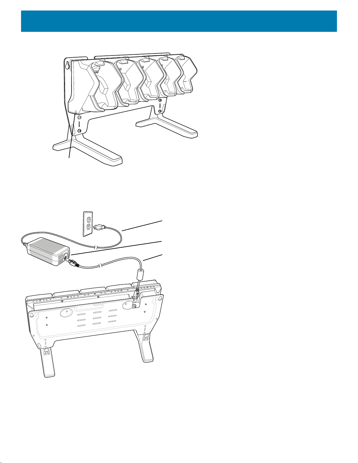
Setup
Power LED
DC Line Cord
Power Supply
AC Line Cord
Accessories
Figure 16 5-Slot Charge Only Cradle (Shown on Optional Desk Mount)
Figure 17 5-Slot Charge Only Cradle Setup (Shown on Optional Desk Mount)
Charging the Device
1. Insert the device into a slot to begin charging.
35
Page 36

Figure 18 Insert Device into Cradle
2. Ensure the device is seated properly.
Battery Charging
Accessories
Main Battery Charging
The device’s Charging/Notification LED indicates the status of the battery charging in the device. The 6,700
mAh battery charges from 0 - 90% in less than four hours at room temperature. The 7,000 mAh battery
charges from 0 - 90% in less than five hours at room temperature.
Charging Temperature
Charge batteries in temperatures from 0 °C to 40 °C (32 °F to 104 °F). The device always performs battery
charging in a safe and intelligent manner. At higher temperatures (e.g. approximately +37 °C (+98 °F)) the
device may for small periods of time alternately enable and disable battery charging to keep the battery at
acceptable temperatures.
5-Slot Charge Only Cradle with Battery Charger
CAUTION
The 4-Slot Charge Only Cradle with Battery Charger:
• Provides 5 VDC (nominal) power for operating the device.
• Simultaneously charges up to four devices.
• Charges up to four spare batteries.
:
Ensure that you follow the guidelines for battery safety described in
Battery Safety Guidelines on page 167
.
36
Page 37

Setup
Spare Battery Charging LED (4)
Power LED
DC Line Cord
Power Supply
AC Line Cord
Accessories
Figure 19 5-Slot Charge Only Cradle with Battery Charger (Shown on Optional Desk Mount)
Figure 20 5-Slot Charge Only Cradle with Battery Charger Setup (Shown on Optional Desk Mount)
Charging the Device
1. Insert the device into a slot to begin charging.
37
Page 38

Figure 21 Insert Device into Cradle
2. Ensure the device is seated properly.
Battery Charging
Accessories
Main Battery Charging
The device’s Charging/Notification LED indicates the status of the battery charging in the device. The 6,700
mAh battery charges from 0 - 90% in less than four hours at room temperature. The 7,000 mAh battery
charges from 0 - 90% in less than five hours at room temperature.
Spare Battery Charging
The Spare battery Charging LED on the cup indicates the status of the spare battery charging. The 6,700 mAh
battery charges from 0 - 90% in less than four hours at room temperature. The 7,000 mAh battery charges
from 0 - 90% in less than five hours at room temperature.
Table 6 Spare Battery Charging LED Indicators
State Indication
Off The battery is not charging. The battery is not inserted correctly in the cradle or
connected to a power source. Cradle is not powered.
Solid Amber Healthy battery is charging.
Solid Green Healthy battery charging is complete.
Fast Blinking Red
(2 blinks/second)
Charging error, e.g.:
- Temperature is too low or too high.
- Charging has gone on too long without completion (typically eight hours).
Solid Red Unhealthy battery is charging or fully charged.
Charging Temperature
Charge batteries in temperatures from 0 °C to 40 °C (32 °F to 104 °F). The device always performs battery
charging in a safe and intelligent manner. At higher temperatures (e.g. approximately +37 °C (+98 °F)) the
38
Page 39

device may for small periods of time alternately enable and disable battery charging to keep the battery at
100/10 LED
1000 LED
acceptable temperatures.
5-Slot Ethernet Cradle
Accessories
CAUTION
:
Ensure that you follow the guidelines for battery safety described in
The 5-Slot Ethernet Cradle:
• Provides 5.0 VDC (nominal) power for operating the device.
• Connects the device (up to five) to an Ethernet network.
• Simultaneously charges up to five devices.
Figure 22 5-Slot Ethernet Cradle (Shown on Optional Desk Mount)
Battery Safety Guidelines on page 167
.
To setup the 5-Slot Ethernet cradle:
39
Page 40

Accessories
DC Line Cord
Power Supply
AC Line Cord
Router
Ethernet Cable
Primary Port
Figure 23 5-Slot Ethernet Cradle with Battery Charger Setup (Shown on Optional Desk Mount)
1. Connect the DC line cord to power supply.
2. Connect DC line cord to power input on cradle.
3. Connect Ethernet cable to Ethernet port 1 on cradle.
4. Connect other end of Ethernet cable to router port.
5. Connect the AC line cord to the power supply.
6. Plug the AC line cord into an AC outlet.
Charging the Device
To charge the device:
1. Insert the device into a slot to begin charging.
40
Page 41

Figure 24 Insert Device into Cradle
2. Ensure the device is seated properly.
Battery Charging
Accessories
Main Battery Charging
The device’s Charging/Notification LED indicates the status of the battery charging in the device. The 6,700
mAh battery charges from 0 - 90% in less than four hours at room temperature. The 7,000 mAh battery
charges from 0 - 90% in less than five hours at room temperature.
Charging Temperature
Charge batteries in temperatures from 0 °C to 40 °C (32 °F to 104 °F). The device or cradle always performs
battery charging in a safe and intelligent manner. At higher temperatures (e.g. approximately +37 °C (+98 °F))
the device or cradle may for small periods of time alternately enable and disable battery charging to keep the
battery at acceptable temperatures. The device and cradle indicates when charging is disabled due to
abnormal temperatures via its LED.
Daisy-chaining Ethernet Cradles
Daisy-chain up to ten 5-Slot Ethernet cradles to connect several cradles to an Ethernet network. Use either a
straight or crossover cable. Daisy-chaining should not be attempted when the main Ethernet connection to the
first cradle is 10 Mbps as throughput issues will almost certainly result.
To daisy-chain 5-Slot Ethernet cradles:
1. Connect power to each 5-Slot Ethernet Cradle with Battery Charger.
2. Connect an Ethernet cable to port 1 on the back of the first cradle and to the Ethernet switch.
3. Connect an Ethernet cable to port 2 on the back of the first cradle to port 1 on the back of the second
cradle.
41
Page 42

Accessories
DC Line Cord
(to Power Supply)
DC Line Cord
(to Power Supply)
Ethernet Cable
(to Next Cradle)
Primary Port Secondary Port
Primary Port
Secondary Port
Figure 25 Daisy-Chaining 5-Slot Ethernet Cradles (Shown on Optional Desk Mount)
4. Connect additional cradles as described in step 2 and 3.
Ethernet Settings
The following settings can be configured when using Ethernet communication:
• Proxy Settings
• Static IP.
Configuring for a Proxy Server
A proxy server is a server that acts as an intermediary for requests from clients seeking resources from other
servers. A client connects to the proxy server and requests some service, such as a file, connection, web
page, or other resource, available from a different server. The proxy server evaluates the request according to
its filtering rules. For example, it may filter traffic by IP address or protocol. If the request is validated by the
filter, the proxy provides the resource by connecting to the relevant server and requesting the service on behalf
of the client.
It is important for enterprise customers to be able to set up secure computing environments within their
companies, making proxy configuration essential. Proxy configuration acts as a security barrier ensuring that
the proxy server monitors all traffic between the Internet and the intranet. This is normally an integral part of
security enforcement in corporate firewalls within intranets.
To configure the device for a proxy server:
1. Swipe down from the Status bar to open the Quick Access panel and then touch .
2. Touch Network & Internet > Ethernet.
42
Page 43

Accessories
3. Place the device into the Ethernet cradle slot.
4. Slide the switch to the On position.
5. Touch and hold eth0 until the menu appears.
6. Touch Modify proxy.
7. Touch the Proxy drop-down list and select Manual.
Figure 26 Ethernet Proxy Settings
8. In the Proxy hostname text box, enter the address of the proxy server.
9. In the Proxy port text box, enter the port number for the proxy server.
10.In the Bypass proxy for text box, enter addresses for web sites that are not required to go through the
proxy server. Use the separator “|” between addresses. Do not use spaces or carriage returns between
addresses.
11.Touch Modify.
12.Touch .
Configuring Ethernet Static IP Address
The device includes Ethernet cradle drivers. After inserting the device, configure Ethernet connection:
1. Swipe down from the Status bar to open the Quick Access panel and then touch .
2. Touch Network & Internet > Ethernet.
3. Place the device into the Ethernet cradle slot.
4. Slide the switch to the On position.
5. Touch Eth0.
6. Touch Disconnect.
7. Touch Eth0.
8. Touch and hold the IP Settings drop-down list and select Static.
43
Page 44

Figure 27 Static IP Settings
Accessories
9. In the IP address field, enter the proxy server address.
10.If required, in the Gateway text box, enter a gateway address for the device.
11.If required, in the Netmask field, enter the network mask address.
12.If required, in the DNS address fields, enter a Domain Name System (DNS) address.
13.Touch Connect.
14.Touch .
LED Indicators
There are two green LEDs on the side of the cradle and on each Ethernet port. These green LEDs light and
blink to indicate the data transfer rate.
Table 7 LED Data Rate Indicators
Data Rate 1000 LED 100/10 LED
1 Gbps On/Blink Off
100 Mbps Off On/Blink
10 Mbps Off On/Blink
Establishing Ethernet Connection
1. Swipe down from the status bar to open the quick access panel and then touch > Network & Internet >
Ethernet.
2. Slide the Ethernet switch to the ON position.
44
Page 45

Accessories
Spare Battery Charging LED (4)
100/10 LED
1000 LED
3. Insert the device into a slot.
4. The icon appears in the Status bar.
5. Touch Eth0 to view Ethernet connection details.
5-Slot Ethernet Cradle with Battery Charger
CAUTION
:
Ensure that you follow the guidelines for battery safety described in
Battery Safety Guidelines on page 167
The 5-Slot Ethernet Cradle with Battery Charger:
• Provides 5.0 VDC (nominal) power for operating the device.
• Connects the device (up to five) to an Ethernet network.
• Simultaneously charges up to four devices.
• Simultaneously charges up to four spare batteries.
Figure 28 5-Slot Ethernet Cradle with Battery Charger (Shown on Optional Desk Mount)
.
45
Page 46

Setup
DC Line Cord
Power Supply
AC Line Cord
Router
Ethernet Cable
Primary Port
Accessories
To setup the 5-Slot Ethernet cradle:
Figure 29 5-Slot Ethernet Cradle with Battery Charger Setup (Shown on Optional Desk Mount)
Charging the Device
1. Connect the DC line cord to power supply.
2. Connect DC line cord to power input on cradle.
3. Connect Ethernet cable to Ethernet port 1 on cradle.
4. Connect other end of Ethernet cable to router port.
5. Connect the AC line cord to the power supply.
6. Plug the AC line cord into an AC outlet.
To charge the device:
1. Insert the device into a slot to begin charging.
46
Page 47

Figure 30 Insert Device into Cradle
2. Ensure the device is seated properly.
Battery Charging
Accessories
Main Battery Charging
The device’s Charging/Notification LED indicates the status of the battery charging in the device. The 6,700
mAh battery charges from 0 - 90% in less than four hours at room temperature. The 7,000 mAh battery
charges from 0 - 90% in less than five hours at room temperature.
Spare Battery Charging
The Spare battery Charging LED on the cup indicates the status of the spare battery charging. The 6,700 mAh
battery charges from 0 - 90% in less than four hours at room temperature. The 7,000 mAh battery charges
from 0 - 90% in less than five hours at room temperature.
Table 8 Spare Battery Charging LED Indicators
State Indication
Off The battery is not charging. The battery is not inserted correctly in the cradle or
connected to a power source. Cradle is not powered.
Solid Amber Healthy battery is charging.
Solid Green Healthy battery charging is complete.
Fast Blinking Red
(2 blinks/second)
Charging error, e.g.:
- Temperature is too low or too high.
- Charging has gone on too long without completion (typically eight hours).
Solid Red Unhealthy battery is charging or fully charged.
Charging Temperature
Charge batteries in temperatures from 0 °C to 40 °C (32 °F to 104 °F). The device or cradle always performs
battery charging in a safe and intelligent manner. At higher temperatures (e.g. approximately +37 °C (+98 °F))
the device or cradle may for small periods of time alternately enable and disable battery charging to keep the
47
Page 48

battery at acceptable temperatures. The device and cradle indicates when charging is disabled due to
Spare Battery Charging LED (4)
abnormal temperatures via its LED.
Daisy-chaining Ethernet Cradles
See Daisy-chaining Ethernet Cradles on page 41.
Ethernet Settings
See Ethernet Settings on page 42.
Establishing Ethernet Connection
1. Swipe down from the status bar to open the quick access panel and then touch > Network & Internet >
Ethernet.
2. Slide the Ethernet switch to the ON position.
3. Insert the device into a slot.
Accessories
4. The icon appears in the Status bar.
5. Touch Eth0 to view Ethernet connection details.
4-Slot Battery Charger
This section describes how to use the 4-Slot Battery Charger to charge up to four device batteries.
Figure 31 4-Slot Battery Charger
48
Page 49

Setup
Power Supply
AC Line Cord
Accessories
Figure 32 Four Slot Battery Charger Power Setup
Charging Spare Batteries
1. Connect the charger to a power source.
2. Insert the battery into a battery charging well and gently press down on the battery to ensure proper
contact.
The Spare Battery Charging LED on the cup indicates the status of the spare battery charging. The 6,700 mAh
battery charges from 0 - 90% in less than four hours at room temperature. The 7,000 mAh battery charges
from 0 - 90% in less than five hours at room temperature.
Table 9 Spare Battery Charging LED Indicators
State Indication
Off The battery is not charging. The battery is not inserted correctly in the cradle or
connected to a power source. Cradle is not powered.
Solid Amber Healthy battery is charging.
Solid Green Healthy battery charging is complete.
Fast Blinking Red
(2 blinks/second)
Solid Red Unhealthy battery is charging or fully charged.
Charging error, e.g.:
- Temperature is too low or too high.
- Charging has gone on too long without completion (typically eight hours).
49
Page 50

Charging Temperature
Charge batteries in temperatures from 0 °C to 40 °C (32 °F to 104 °F). The device or cradle always performs
battery charging in a safe and intelligent manner. At higher temperatures (e.g. approximately +37 °C (+98 °F))
the device or cradle may for small periods of time alternately enable and disable battery charging to keep the
battery at acceptable temperatures. The device and cradle indicates when charging is disabled due to
abnormal temperatures via its LED.
2-Slot Desk Bracket
Use the 2-Slot Desk Mount to mount the 2-Slot USB Charging cradle in a vertical position.
Figure 33 2-Slot Desk Mount
Accessories
Assembly
To assemble the 2-Slot Desk Mount:
1. Align plate mounting holes with holes in feet.
50
Page 51

Accessories
Screws (4)
Plate
Feet (2)
Studs (3)
Figure 34 Install Feet
2. Secure plate to feet with four screws and four washers.
Mounting Cradle
To mount the cradle:
1. Align mounting slots on bottom of cradle with studs on plate.
Figure 35 Install Cradle onto Desk Mount
2. Secure cradle to plate using safety screw.
51
Page 52

Figure 36 Install Safety Screw
Safety Screw
Accessories
5-Slot Desktop Bracket
Use the 5-Slot Desk Mount to mount the 5-Slot Charge Only cradles or the 5-Slot Ethernet cradles in a vertical
position.
Figure 37 5-Slot Desk Mount
Assembly
To assemble the 5-Slot Desk Mount:
1. Align plate mounting holes with holes in feet.
52
Page 53

Figure 38 Install Feet
Screws (4)
Plate
Feet (2)
Studs (4)
Accessories
2. Secure plate to feet with four screws and four washers.
Mount Cradle
To mount the cradle:
1. Align mounting slots on bottom of cradle with studs on plate.
Figure 39 Install Cradle onto Desk Mount
53
Page 54

Accessories
Safety Screws (2)
2. Secure cradle to plate using two safety screws.
Figure 40 Install Safety Screws
Cart Mount
Use the Cart Mount to hold the device and perform hands-free scanning in Presentation Mode.
Figure 41 Cart Mount
54
Page 55

Installation
RAM Mount Ball Base
RAM Mount Socket Arm
RAM Mount Claw Base
RAM Mount Ball Base
To assemble the Cart Mount and RAM Mount:
1. Secure the RAM Mount ball base to the bottom of the Cart Mount using four screws and four washers
(provided).
2. Insert the socket arm to the ball base and claw base.
3. Slightly tighten the knob on the socket arm.
Figure 42 Cart Mount Assembly
Accessories
4. Squeeze the claw base and install on a cart rail.
55
Page 56

Accessories
Claw Knob
Socket Arm Knob
Figure 43 Cart Mount Installation on Cart Rail
5. Position the Cart Mount and tighten the claw knob and socket arm knob.
6. Insert the device handle into the Cart Mount cradle and rotate into the cradle.
5-Slot Cradle Rack Installation
Use the Rack/Wall Mount Bracket to mount a 5-slot cradle on a rack. When installing on a rack, first assemble
the bracket and cradles/chargers and then install the assembly on the rack.
1. Place the power supply in bottom tray.
2. Connect AC line cord to power supply.
3. Connect DC line cord to power supply.
4. Secure power supply and cables to bottom tray with tie wraps.
NOTE
:
Ensure tie wrap buckle is on side of power supply. Tie wrap buckle on top of power supply interferes with top tray.
5. Route cables through cable slots.
56
Page 57

Accessories
DC line Cord AC line CordPower Supply
Studs (4)
Figure 44 Power Supply in Bottom Tray
6. Secure four M2.5 studs to top tray as shown.
Figure 45 Install Studs
7. Align and install 5-Slot cradle onto studs of top tray.
57
Page 58

Accessories
Safety Screws(2)
Figure 46 Align Cradle on Studs
8. Secure cradle to top tray with two M2.5 safety screws.
Figure 47 Secure Cradle
9. Slide top tray onto bottom tray.
58
Page 59

Accessories
Figure 48 Slide Top Trap onto Bottom Tray
10.Connect cables to cradle.
Figure 49 Connect Cables
11.Secure top tray to bottom tray with 4 M5 screws (two on each side).
59
Page 60

Accessories
Figure 50 Secure Top and Bottom Tray
See Rack Mount Installation on page 63 for installing the bracket assembly onto a rack.
4-Slot Battery Chargers Rack Installation
Use the Rack/Wall Mount Bracket to mount four 4-Slot Battery Chargers on a rack. When installing on a rack,
first assemble the bracket and chargers and then install the assembly on the rack.
1. Place one power supply horizontally in bottom tray.
2. Place one power supply vertically in bottom tray.
3. Connect AC line cords to power supplies.
4. Connect DC line cords to power supplies.
5. Secure power supplies and cables to bottom tray with tie wraps.
6. Route cables through cable slots.
60
Page 61

Accessories
DC Y Cable 2
AC line Cord 2
Power Supply 1
Power Supply 2
AC line Cord 1
DC Y Cable 1
Figure 51 Power Supplies in Bottom Tray
7. Slide top tray onto bottom tray until top tray touches vertical power supply.
Figure 52 Slide top Tray onto Bottom Tray
8. Install 16 M2.5 studs onto top tray as shown below.
61
Page 62

Accessories
Studs (16)
Figure 53 Install Studs
9. Align and install 4-Slot Battery Charger onto four studs.
Figure 54 Align Chargers on Studs
10.Connect DC Y cables to four 4-Slot Battery Chargers.
62
Page 63

Figure 55 Connect Cables
Accessories
11.Secure top tray to bottom tray with four M5 screws (two on each side).
Figure 56 Secure Top Tray to Bottom Tray
See Rack Mount Installation on page 63 for installing the bracket onto a rack.
Rack Mount Installation
63
Page 64

Accessories
Top Screw Hole
Flange
Fourth Screw Hole
Flange
NOTE
:
Use screws provided with rack system. Refer to rack user documentation for instructions.
1. Secure mounting brackets to both sides of top tray with four M5 screws (two on each side). For 5-Slot
cradles, position the flange for vertical installation. For 4-Slot Battery Chargers, position the flange for 25°
installation.
Figure 57 Flange Vertical Position (5-Slot Cradles)
Figure 58 Flange 25° Position (4-Slot Battery Chargers)
2. Install two rack system screws for top of mounting brackets. The screw heads should protrude half way
from the rail.
64
Page 65

Figure 59 Install Rack System Screws
Rack Screws
Accessories
3. Align the mounting bracket’s top mounting key holes with the screws.
4. Place the brackets on the screws.
Figure 60 Secure Bracket to Rack (Vertical Position Shown)
5. Secure the top screws.
6. Install bottom screws and tighten screws.
7. Route cables and connect to power source.
CAUTION
:
Installer should ensure that all building codes are followed when connecting the power supplies to an AC power
65
Page 66

source.
While installing the brackets, power supplies and cables:
• Use tie wraps to secure cables to the bracket and rails.
• Coil cables wherever possible.
• Route power cables along the rails.
• Route inter-cradle cables to the side rails and then from the rails to the bracket.
5-Slot Cradle Wall Installation
Use the Rack/Wall Mount Bracket to mount a cradle on a wall. When installing on a wall, first assemble the
bottom tray, install the bottom tray on the wall and then assemble the top tray.
Use mounting hardware (screws and/or anchors) appropriate for the type of wall mounting the bracket onto.
The Mount Bracket mounting slots dimensions are 5 mm (0.2 in.). Fasteners must be able to hold a minimum
of 20 Kg (44 lbs.)
For proper installation consult a professional installer. Failure to install the bracket properly can possibly result
in damage to the hardware.
Accessories
Bottom Tray Assembly
See steps 1 through 5 in 5-Slot Cradle Rack Installation on page 56.
Bracket Wall Mounting
1. Drill holes and install anchors according to the template supplied with the bracket.
2. Install two screws for bottom of bracket. The screw heads should protrude 2.5 mm (0.01”) from the wall.
66
Page 67

Accessories
406 mm
137.8 mm
Figure 61 Vertical Wall Mounting Dimensions
3. Align the mounting bracket’s bottom mounting key holes with the screws.
4. Hang the bracket on the screws.
67
Page 68

Figure 62 Vertical Installation
Accessories
5. Install two top screws.
6. Tighten all screws.
Figure 63 Horizontal Installation - Tighten Screws
7. Assemble the top tray. See steps 6 through 8 in 5-Slot Cradle Rack Installation on page 56.
8. Slide the assembled top tray onto bottom tray.
68
Page 69

Accessories
9. Connect cables to cradle.
10.Secure top tray to bottom tray with four M5 screws (two on each side).
11.Route cables and connect to power source.
CAUTION
source.
:
Installer should ensure that all building codes are followed when connecting the power supplies to an AC power
While installing the brackets, power supplies and cables:
• Use tie wraps to secure cables to the bracket.
• Coil cables wherever possible.
• Route power cables along wall and secure.
4-Slot Battery Charger Wall Installation
Use the Rack/Wall Mount Bracket to mount four 4-Slot Battery Chargers a cradle on a wall. When installing on
a wall, first assemble the bottom tray, install the bottom tray on the wall and then assemble the top tray.
Use mounting hardware (screws and/or anchors) appropriate for the type of wall mounting the bracket onto.
The Mount Bracket mounting slots dimensions are 5 mm (0.2 in.). Fasteners must be able to hold a minimum
of 20 Kg (44 lbs.)
For proper installation consult a professional installer. Failure to install the bracket properly can possibly result
in damage to the hardware.
Bottom Tray Assembly
See steps 1 through 5 in 4-Slot Battery Chargers Rack Installation on page 60.
Bracket Wall Mounting
1. Drill holes and install anchors according to the template supplied with the bracket.
2. Install two screws for bottom of bracket. The screw heads should protrude 2.5 mm (0.01”) from the wall.
69
Page 70

Accessories
22.85 mm
398 mm
Figure 64 Horizontal Mounting Template
3. Align the mounting bracket’s bottom mounting key holes with the screws.
4. Hang the bracket on the screws.
Figure 65 Horizontal Installation
5. Install two top screws.
6. Tighten all screws.
70
Page 71

Accessories
Figure 66 Horizontal Installation - Tighten Screws
7. Assemble the four 4-Slot Battery Chargers onto the bracket. See steps 7 through 11 in 4-Slot Battery
Chargers Rack Installation on page 60.
8. Route cables and connect to power source.
CAUTION
source.
:
Installer should ensure that all building codes are followed when connecting the power supplies to an AC power
While installing the brackets, power supplies and cables:
• Use tie wraps to secure cables to the bracket and rails.
• Coil cables wherever possible.
• Route power cables along the rails.
• Route inter-cradle cables to the side rails and then from the rails to the bracket.
Condensation Resistant Rear Bezel Replacement
The Condensation Resistant configurations contain a desiccant pack that must be replaced every five months.
The desiccant pack is part of the Back Bezel. Replacement Back Bezel with desiccant pack comes in a
vacuum sealed package. Do not open the package until instructed in the steps below. Install immediately after
opening.
To replace the Back Bezel:
1. Remove six screws securing the Back Bezel.
71
Page 72

Figure 67 Remove Screws
2. Lift Rear Bezel.
Accessories
Figure 68 Lift Rear Bezel
3. Cut the package open with scissors.
72
Page 73

Figure 69 Open Vacuum Bag
Accessories
4. Remove Rear Bezel from package.
5. Align Rear Bezel with device.
Figure 70 Align Back Bezel
6. Secure Rear Bezel using six screws with a torque requirement of 4.5±0.2 kgf.cm.
73
Page 74

Figure 71 Secure Back Bezel
1
6
4
3
5
2
Accessories
74
Page 75

USB Communication
Introduction
This chapter provides information for transferring files between the device and a host computer.
Transferring Files with a Host Computer via USB
Connect the device to a host computer using a USB cable to transfer files between the device and the host
computer.
When connecting the device to a host computer, follow the host computer’s instructions for connecting and
disconnecting USB devices, to avoid damaging or corrupting files.
Transferring Files
NOTE
:
Use Transfer files to copy files between the device (internal memory) and the host computer.
1. Connect a USB cable to the device.
2. Pull down the Notification panel and touch USB charging this device.
By default, Charge this device is selected.
Figure 1 Use USB to Dialog Box
3. Touch Transfer files.
4. On the host computer, open a file explorer application.
5. Locate the device as a portable device.
75
Page 76

USB Communication
6. Open the Internal storage folder.
7. Copy files to and from the device or delete files as required.
Connecting to the TC8300 as a Media Device
NOTE
:
Using Media Device, you can copy files to either the microUSB card or internal memory.
1. Connect the USB Charge cable to the device and then to the host computer.
2. Connected as a media device or Connected as a camera appears on the Status bar.
3. If Connected as a camera appears, pull down the Notification shade and touch Connected as a camera
and then touch Media device (MTP).
4. On the host computer, open a file explorer application.
5. Locate the TC8300 as a portable device.
6. Open the SD card, Internal storage or Enterprise storage folder.
7. Copy or delete files as required.
Connecting to the TC8300 as a Camera
NOTE
:
Using Camera, you can copy files to internal memory.
1. Connect the USB and Charging cable to the device and then to the host computer.
2. Connected as a media device or Connected as a camera or appears on the Status bar.
3. If Connected as a media device appears, pull down the Notification shade and touch Connected as a
media device and then touch Camera (PTP).
4. On the host computer, open a file explorer application.
5. Locate the TC8300 as a portable device.
6. Open the Internal storage folder.
7. Copy or delete photos as required.
Disconnect from the Host Computer
To disconnect the device from the host computer:
CAUTION
1. On the host computer, unmount the device.
2. Remove the USB from the device.
:
Carefully follow the host computer’s instructions to disconnect USB devices correctly to avoid losing information.
76
Page 77

DataWedge
Introduction
This chapter applies to DataWedge on Android devices. DataWedge is an application that reads data,
processes the data and sends the data to an application.
Accessing DataWedge
To access DataWedge:
1. Swipe up from the bottom of the Home screen and touch .
Basic Scanning
Scanning can be performed using the following:
Profiles
DataWedge is based on profiles and plug-ins. A profile contains information on how DataWedge
should behave with different applications.
Profile information consists of:
• Associated application
• Input plug-in configurations
• Output plug-in configurations
• Process plug-in configurations.
Using profiles, each application can have a specific DataWedge configuration. For example, each user
application can have a profile which outputs scanned data in the required format when that application
comes to the foreground. DataWedge can be configured to process the same set of captured data
differently based on the requirements of each application.
DataWedge includes the following pre-configured profiles which support specific built-in applications:
77
Page 78

Profile0
DataWedge
• Visible profiles:
• Profile0 - created automatically the first time DataWedge runs. Generic profile used when there are no
user created profiles associated with an application.
• Launcher - enables scanning when the Launcher is in foreground.
• DWDemo - provides support for the DWDemo application.
Some Zebra applications are capable of capturing data by scanning. DataWedge is pre-loaded with private
and hidden profiles for this purpose. There is no option to modify the private profiles.
Profile0 can be edited but cannot be associated with an application. That is, DataWedge allows manipulation
of plug-in settings for Profile0 but it does not allow assignment of a foreground application. This configuration
allows DataWedge to send output data to any foreground application other than applications associated with
user-defined profiles when Profile0 is enabled.
Profile0 can be disabled to allow DataWedge to only send output data to those applications which are
associated in user-defined profiles. For example, create a profile associating a specific application, disable
Profile0 and then scan. DataWedge only sends data to the application specified in the user-created profile.
This adds additional security to DataWedge enabling the sending of data only to specified applications.
Plug-ins
A plug-in is a software module utilized in DataWedge to extend its functionality to encompass technologies
such as barcode scanning. The plug-ins can be categorized into three types based on their operations:
• Input Plug-ins
• Output Plug-ins
• Process Plug-ins.
Input Plug-ins
An Input Plug-in supports an input device, such as a barcode scanner contained in, or attached to the device.
DataWedge contains base plug-ins for these input devices.
Barcode Scanner Input Plug-in – The Barcode Scanner Input Plug-in is responsible for reading data from the
integrated barcode scanner and supports different types of barcode readers including laser, imager and
internal camera. Raw data read from the barcode scanner can be processed or formatted using Process
Plug-ins as required. DataWedge has built-in feedback functionality for the barcode scanner to issue user
alerts. The feedback settings can be configured according to user requirement.
Process Plug-ins
Process Plug-ins are used in DataWedge to manipulate the received data according to the requirement,
before sending to the foreground application via the Output Plug-in.
• Basic Data Formatting Process Plug-in – The Basic Data Formatting Plug-in allows DataWedge to add a
prefix and/or a suffix to the captured data before passing it to an Output Plug-in.
• Advanced Data Formatting Process Plug-in – The Advanced Data Formatting Plug-in allows
DataWedge to apply rules (actions to be performed based on defined criteria) to the data received via an
input plug-in before passing it to an Output Plug-in.
78
Page 79

Output Plug-ins
Output Plug-ins are responsible for sending the data from Input Plug-ins to a foreground application on the
device.
• Keystroke Output Plug-in – The Keystroke Output Plug-in collects and sends data received from the Input
Plug-in to the foreground applications by emulating keystrokes.
• Intent Output Plug-in – The Intent Output Plug-in collects and sends data received from the Input Plug-ins
to foreground applications using the Android Intent mechanism.
• IP Output Plug-in – The IP Output Plug-in collects and sends data received from the Input Plug-ins to a
host computer via a network connection. Captured data can be sent over an IP network to a specified IP
address and port using either TCP or UDP transport protocols.
Profiles Screen
To launch DataWedge, swipe up from the bottom of the screen and touch . By default, three profiles appear:
•Profile0
• Launcher
•DWDemo
DataWedge
Profile0 is the default profile and is used when no other profile can be applied.
Figure 1 DataWedge Profiles Screen
Profile names are color coded. Enabled profiles are white and disabled profiles are gray.
To configure a profile touch the profile name.
Profile Context Menu
Touch and hold a profile to open a context menu that allows additional actions to be performed on the selected
profile.
79
Page 80

Figure 2 Profile Context Menu
The profile context menu allows the profile to be edited (same as just tapping on a profile), renamed or deleted.
Options Menu
Touch to open the options menu.
Figure 3 DataWedge Options Menu
DataWedge
The menu provides options to create a new profile, access to general DataWedge settings and DataWedge
version information.
Disabling DataWedge
1. Swipe up from the bottom of the screen and touch .
2. Touch .
3. Touch Settings.
4. Touch DataWedge enabled.
The blue check disappears from the checkbox indicating that DataWedge is disabled.
Creating a New Profile
To create a new profile:
1. Swipe up from the bottom of the screen and touch .
2. Touch .
3. Touch New profile.
4. In the New profile dialog box, enter a name for the new profile. It is recommended that profile names be
unique and made up of only alpha-numeric characters (A-Z, a-z, 0-9).
80
Page 81

Figure 4 New Profile Name Dialog Box
5. Touch OK.
The new profile name appears in the DataWedge profile screen.
Profile Configuration
To configure the Profile0 or a user-created profile, touch the profile name.
Figure 5 Profile Configuration Screen
DataWedge
The configuration screen lists the following sections:
• Profile enabled
• Applications
• Data Capture Plus (DCP)
• Barcode Input
• Keystroke output
• Intent Output
•IP Output.
81
Page 82

Associating Applications
Use Applications option to associate applications with this profile. User created profiles should be associated
with one or more applications and its activities.
1. Touch Associated apps. A list of applications/activities associated with the profile displays. Initially the list
does not contain any applications/activities.
Figure 6 Associated Apps Screen
DataWedge
2. Touch .
3. Touch New app/activity.
Figure 7 Select Application Menu
82
Page 83

DataWedge
4. In the Select application screen, select the desired application from the list.
5. In the Select activity menu, selecting the activity adds that application/activity combination to the
associated application list for that profile. Selecting * as the activity results in all activities within that
application being associated to the profile. During operation, DataWedge tries to match the specific
application/activity combinations with the foreground application/activity before trying to match the general
application/* combinations.
6. Touch .
Figure 8 Selected Application/Activity
Data Capture Plus
Data Capture Plus (DCP) is a DataWedge feature that enables the user to initiate data capture by touching a
designated part of the screen. A variable screen overlay acts like a scan button.
83
Page 84

Figure 9 Minimized Data Capture Panel
DCP Button
DataWedge
The DataWedge profile configuration screen allows the user to configure how the DCP appears on the screen
once the particular profile is enabled. The DCP is hidden by default. Enabling DCP option displays seven
additional configuration parameters.
Figure 10 Data Capture Panel Settings
• Enable - Select to enable Data Capture Plus (default - disabled).
• Dock button on - Select position of the button.
• Left or right - Allows user to place the button on either the right or left edge of the screen.
• Left only - Places the button on left edge of the screen.
• Right only - Places the button on the right edge of the screen.
84
Page 85

DataWedge
• Start in - Select the initial DCP state.
• Fullscreen mode - DCP covers the whole screen.
• Button mode - DCP displays as a circular button on the screen and can be switched to fullscreen mode.
• Button only mode - DCP displays as a circular button on the screen and cannot be switched to
fullscreen mode.
• Button highest position - Select the top of the range the user is allowed to move the DCP, given as a
percent of the screen height (default - 0).
• Button lowest position - Select the bottom of the range the user is allowed to move the DCP, given as a
percent of the screen height (default - 100).
• Drag detect time - Select the time in milliseconds that the scanner waits before activating scanner. This
allows the user to drag the button without initiating scanner (default - 100 ms, maximum 1000 ms).
NOTE
:
The DCP does not appear if the scanner is disabled in the profile even though the
In Button mode, the user can place DCP in full screen mode by dragging the button over Fullscreen mode.
The overlay covers the screen.
Figure 11 Maximized DCP
Enabled
option is set.
Swipe down to return to button mode.
Barcode Input
Use the Barcode Input options to configure the Barcode Scanner Input Plug-in for the profile.
Enabled
Enables or disables this plug-in. A check in the checkbox indicates that the plug-in is enabled.
Scanner Selection
Configures which scanning device to use for barcode data capture when the profile is active.
85
Page 86

DataWedge
• Auto ( 2D Barcode Imager)
• 2D Barcode Imager
• Auto (Serial SSI Scanner)
• Serial SSI Scanner
• Camera Scanner
• Bluetooth Scanner
• RS6000 Bluetooth Scanner
• DS3678 Bluetooth Scanner
• LI3678 Bluetooth Scanner
• DS2278 Bluetooth Scanner
• DS8178 Bluetooth Scanner
Hardware Trigger
Enables or disables the hardware trigger for scanning (Default - enabled). If disabled, pressing the hardware
trigger will not scan a barcode. When the hardware trigger is disabled, it cannot be used for starting the
scanning beam, but if scanning is started by a soft scan trigger intent, then a hardware trigger press cancels
the scan.
Auto Switch to Default on Event
This feature configures DataWedge to select an external scanner as the default scanning device immediately
upon connection and revert to a built-in scanner when the external scanner is disconnected. External scanners
include those connecting by Bluetooth, serial cable or snap-on module. Disabled by default. This is only
available when Scanner Selection is set to Auto.
This helps reduce scanning workflow interruptions when a Bluetooth scanner is introduced and/or it becomes
disconnected due to losing power or moving out of range.
For Bluetooth scanners, if the device was not previously paired, a pairing barcode displays prior to automatic
connection.
• Disabled - No scanner switching occurs when an external scanner is connected or disconnected (default).
• On connect - Selects the external scanner as the default scanning device immediately upon connection.
• On disconnect - Reverts to a built-in scanner based on its position in an internally managed scanner list
(which varies by host device). This is usually the scanner most recently used prior to the external
connection (see notes below).
• On connect/disconnect - Selects an external scanner as the default scanning device immediately upon
connection. Upon disconnection, reverts to the scanner set as the default prior to the external connection.
NOTE
:
The system selects the default scanner based on the connection state and the scanner's position in an internally
managed scanner list. If the newly connected scanner is lower in the scanner list than the one currently selected as the de
fault scanner, the newly connected scanner becomes the default scanner.
-
On devices with only one built-in scanner or imager, On disconnect reverts to that built-in scanner or imager.
Configure Scanner Settings
Select Configure Scanner Settings to set the following:
• Select scanner to set parameters
• Decoders
86
Page 87

DataWedge
• Decoder params
• UPC/EAN params
• Reader params
• Scan params
• UDI params
• Multibarcode params
• Keep enabled on suspend
Select Scanner to Set Parameters
Select a scanner from the available options to set the parameters for or select All Scanners.
Decoders
Configures which barcode decoders are enabled or disabled. For best performance disable all unnecessary
decoders.
Touch Decoders. The Barcode input screen appears. A check in the checkbox indicates that the decoder is
enabled. By default the most commonly used decoders are enabled (shown below with an asterisk). The
supported decoders are:
NOTE
:
DataWedge supports the decoders listed below but not all are validated on this device.
87
Page 88

Table 1 Supported Decoders
DataWedge
Decoders
Camera
Australian
Postal
Aztec X--XXXXX--X
Canadian
Postal
Chinese 2 of 5OOOOOOOOO
Codabar XXXXXXXXX
Code 11 OOOOOOOOO
Code 128 XXXXXXXXX
Code 39 XXXXXXXXX
Code 93 OOOOOOOOO
Composite ABO-- OOOOO-- O
O--OOOOO-- O
O--OOO-- -- -- --
Internal Imager
965
Internal Imager
Internal Imager
SE4750-DP/SE4750-DPA
SE4850-ER, SE4770-SR, SE4750-MR
RS6000
DS2278
DS3678
LI3678
DS8178
Composite CO--OOOOO-- O
Discrete 2 of 5OOOOOOOOO
DatamatrixX--XXXXX--X
Dutch PostalO--OOOOO-- O
DotCode XOXOOOOOO
EAN13 XXXXXXXXX
EAN8 XXXXXXXXX
Grid MatrixOOOOOOOOO
GS1 DataBarXXXXXXXXX
GS1 DataBar
Expanded
GS1 DataBar
Limited
GS1
Datamatrix
GS1 QRCodeO--OOOOO-- O
XXXXXXXXX
OOOOOOOOO
O--OOOOO-- O
88
Page 89

Table 1 Supported Decoders (Continued)
DataWedge
Decoders
Camera
HAN XIN O-- OOOOO--O
Interleaved 2
of 5
Japanese
Postal
Korean 3 of 5OOOOOOOOO
MAIL MARKX--XXXXX--X
Matrix 2 of 5OOOOOOOOO
Maxicode X--XXXXX--X
MicroPDF O-- OOOOO--O
MicroQR O--OOOOO-- O
MSI OOOOOOOOO
OOOOOOOOO
O--OOOOO-- O
Internal Imager
965
Internal Imager
Internal Imager
SE4750-DP/SE4750-DPA
SE4850-ER, SE4770-SR, SE4750-MR
RS6000
DS2278
DS3678
LI3678
DS8178
PDF417 X--XXXXX--X
QR Code X--XXXXX--X
Decoder
Signature
TLC 39 OOOOOOOOO
Trioptic 39 OOOOOOOOO
UK Postal O-- OOOOO--O
UPCA XXXXXXXXX
UPCE0 XXXXXXXXX
UPCE1 ODOOOOOOO
US4state O--OOOOO-- O
US4state FICSO--OOOOO-- O
US Planet O--OOOOO-- O
US PostnetO--OOOOO-- O
Touch to return to the previous screen.
O--OOOO-- -- --
89
Page 90

DataWedge
Decoder Params
Use Decode Params to configure individual decoder parameters.
NOTE
:
Not all parameter options are available with all scanners. See the DataWedge app on each device for the available
scanners and parameter options.
Codabar
• CLSI Editing - Enable this parameter to strip the start and stop characters and insert a space after the first,
fifth, and tenth characters of a 14-character Codabar symbol. Enable this feature if the host system requires
this data format (default - disabled).
• Length1 - Use to set decode lengths (default - 6). See Decode Lengths for more information.
• Length2 - Use to set decode lengths (default - 55). See Decode Lengths for more information.
• NOTIS Editing - Enable this parameter to strip the start and stop characters from a decoded Codabar
symbol. Enable this feature if the host system requires this data format (default - disabled).
• Redundancy - Sets the reader to read the barcode twice before accepting data. A check in the checkbox
indicates that redundancy is enabled (default - enabled).
Code 11
• Length1 - Use to set decode lengths (default - 4). See Decode Lengths for more information.
• Length2 - Use to set decode lengths (default - 55). See Decode Lengths for more information.
• Redundancy - Sets the reader to read the barcode twice before accepting data. A check in the checkbox
indicates that redundancy is enabled (default - enabled).
• Report Check Digit - Transmit Code 11 data with or without the check digit. A check in the checkbox
indicates to send Code 11 data with check digit (default - disabled).
• Verify Check Digit - Check the integrity of all Code 11 symbols to verify that the data complies with the
specified check digit algorithm. This selects the check digit mechanism for the decoded Code 11 barcode.
• No Check Digit - Do not verify check digit.
• 1 Check Digit - Barcode contains one check digit (default).
• 2 Check Digits - Barcode contains two check digits.
Code128
• Code128 Reduced Quiet Zone - Enables decoding of margin-less Code 128 barcodes (default - disabled).
• Ignore Code128 FCN4 - When enabled, and a Code 128 barcode has an embedded FNC4 character, it will
be removed from the data and the following characters will not be changed. When the feature is disabled,
the FNC4 character will not be transmitted but the following character will have 128 added to it (default disabled).
• Check ISBT Table - The ISBT specification includes a table that lists several types of ISBT barcodes that
are commonly used in pairs. If ISBT128 Concat Mode is set, enable Check ISBT Table to concatenate only
those pairs found in this table. Other types of ISBT codes are not concatenated. A check in the checkbox
indicates that redundancy is enabled (default - disabled).
• Enable GS1-128 - Set the GS1 128 subtype. A check in the checkbox indicates that the option is enabled
(default - enabled).
• Enable ISBT128 - Set the ISBT128 subtype. A check in the checkbox indicates that the option is enabled
(default - enabled).
•
Enable Plain Code128 - Set the Plain Code128 subtype. Enables other (non-EAN or ISBT) Code 128
subtypes. A check in the checkbox indicates that the option is enabled (default - enabled).
90
Page 91

DataWedge
• ISBT128 Concatenation Mode - Select an option for concatenating pairs of ISBT code types:
• Concat Mode Never - Do not concatenate pairs of ISBT codes encountered (default).
• Concat Mode Always - There must be two ISBT codes in order to decode and perform concatenation.
Does not decode single ISBT symbols.
• Concat Mode Auto - Decodes and concatenates pairs of ISBT codes immediately. If only a single ISBT
symbol is present, the device must decode the symbol the number of times set via DataWedge
Configuration 4 - 11 Redundancy - Code128 before transmitting its data to confirm that there is no
additional ISBT symbol.
• Length1 - Use to set decode lengths (default - 0). See Decode Lengths for more information.
• Length2 - Use to set decode lengths (default - 55). See Decode Lengths for more information.
• Redundancy - Sets the reader to read the barcode twice before accepting data. A check in the checkbox
indicates that redundancy is enabled (default - disabled).
• Security Level - The scanner offers four levels of decode security for Code 128 barcodes. Select
increasing levels of security for decreasing levels of barcode quality. There is an inverse relationship
between security and scanner aggressiveness, so choose only that level of security necessary for any
given application.
• Security Level 0 - This setting allows the scanner to operate in its most aggressive state, while
providing sufficient security in decoding most “in-spec” barcodes.
• Security Level 1 - This setting eliminates most misdecodes (default).
• Security Level 2 - Select this option if Security level 1 fails to eliminate misdecodes.
• Security Level 3 - If Security Level 2 is selected and misdecodes still occur, select this security level.
Be advised, selecting this option is an extreme measure against mis-decoding severely out of spec
barcodes. Selecting this level of security significantly impairs the decoding ability of the scanner. If this
level of security is needed, try to improve the quality of the barcodes.
Code39
• Code39 Reduced Quiet Zone - Enables decoding of margin-less Code 39 barcodes (default - disabled).
• Convert Code39 To Code32 - Code 32 is a variant of Code 39 used by the Italian pharmaceutical industry.
Scan the appropriate barcode below to enable or disable converting Code 39 to Code 32 (default disabled).
• Full ASCII- Code 39 Full ASCII is a variant of Code 39 that pairs characters to encode the full ASCII
character set. To enable or disable Code 39 Full ASCII (default - disabled),
• Length1 - Use to set decode lengths (default - 0). See Decode Lengths for more information.
• Length2 - Use to set decode lengths 4 (default - 55). See Decode Lengths for more information.
• Redundancy - Sets the reader to read the barcode twice before accepting data. A check in the checkbox
indicates that redundancy is enabled (default - disabled).
• Report Check Digit - Transmit Code 39 data with or without the check digit. A check in the checkbox
indicates to send Code 39 data with check digit (default - disabled).
• Report Code32 Prefix - Scan the appropriate barcode to enable or disable adding the prefix character “A”
to all Code 32 barcodes (default - disabled).
91
Page 92

DataWedge
• Security Level - Options: Security level 0, Security Level 1, Security Level 2 and Security Level 3
(default - Security level 1).
• Security Level 0 - This setting allows the scanner to operate in its most aggressive state, while
providing sufficient security in decoding most “in-spec” barcodes.
• Security Level 1 - This setting eliminates most misdecodes (default).
• Security Level 2 - Select this option if Security level 1 fails to eliminate misdecodes.
• Security Level 3 - If Security Level 2 is selected and misdecodes still occur, select this security level.
Be advised, selecting this option is an extreme measure against mis-decoding severely out of spec
barcodes. Selecting this level of security significantly impairs the decoding ability of the scanner. If this
level of security is needed, try to improve the quality of the barcodes.
• Verify Check Digit - Enable this feature to check the integrity of all Code 39 symbols to verify that the data
complies with a specified check digit algorithm. The digital scanner decodes only those Code 39 symbols
that include a modulo 43 check digit. Enable this feature only if the Code 39 symbols contain a modulo 43
check digit (default - disabled).
Code93
• Length1 - Use to set decode lengths (default - 0). See Decode Lengths for more information.
• Length2 - Use to set decode lengths (default - 55). See Decode Lengths for more information.
• Redundancy - Sets the reader to read the barcode twice before accepting data. A check in the checkbox
indicates that redundancy is enabled (default - disabled).
Composite AB
• UCC Link Mode
• Link Flag ignored - 1D component is transmitted regardless of whether a 2D component is detected.
• Always Linked - 1D and the 2D components are transmitted. If 2D is not present, the 1D component is
not transmitted.
• Auto Discriminate - the digital scanner determines if there is a 2D portion, then transmits the 1D
component, as well as the 2D portion if present. (default).
Discrete 2 of 5
• Length1 - Use to set decode lengths (default - 0). See Decode Lengths for more information.
• Length2 - Use to set decode lengths (default - 14). See Decode Lengths for more information.
• Redundancy - Sets the reader to read the barcode twice before accepting data. A check in the checkbox
indicates that redundancy is enabled (default - enabled).
Grid Matrix
• Inverse - Specify the reflectance for decoding Grid Matrix barcodes.
• Disabled (0) - Decode Grid Matrix barcodes with normal reflectance only.
• Enabled (1) - Decode Grid Matrix barcodes with inverse reflectance only.
• Auto (2)
• Mirror - Specify whether mirrored Grid Matrix barcodes are decoded.
• Disabled (0) - Decode non-mirrored Grid Matrix barcodes only.
• Enabled (1) - Decode mirrored Grid Matrix barcodes only.
• Auto (2) - Decodes both mirrored and non-mirrored Grid Matrix barcodes. (default - enabled).
- Decodes both normal and inverse reflectance Grid Matrix barcodes. (default - enabled).
92
Page 93

DataWedge
GS1 DataBar Limited
• GS1 Limited Security Level
• GS1 Security Level 1 - This setting allows the scanner to operate in its most aggressive state, while
providing sufficient security in decoding most “in-spec” barcodes.
• GS1 Security Level 2 - This setting eliminates most misdecodes (default).
• GS1 Security Level 3 - Select this option if Security level 2 fails to eliminate misdecodes.
• GS1 Security Level 4 - If Security Level 3 is selected and misdecodes still occur, select this security
level. Be advised, selecting this option is an extreme measure against mis-decoding severely out of
spec barcodes. Selecting this level of security significantly impairs the decoding ability of the scanner. If
this level of security is needed, try to improve the quality of the barcodes.
HAN XIN
• HAN XIN Inverse
• Disable - Disables decoding of HAN XIN inverse barcodes (default).
• Enable - Enables decoding of HAN XIN inverse barcodes.
• Auto - Decodes both HAN XIN regular and inverse barcodes.
Interleaved 2 of 5
• Check Digit
• No Check Digit - A check digit is not used. (default)
• USS Check Digit - Select to check the integrity of all Interleaved 2 of 5 symbols to verify the data
complies with either the Uniform Symbology Specification (USS) check digit algorithm.
• OPCC Check Digit - Select to check the integrity of all Interleaved 2 of 5 symbols to verify the data
complies with either the Optical Product Code Council (OPCC) check digit algorithm.
• Length1 - Use to set decode lengths (default - 14). See Decode Lengths for more information.
• Length2 - Use to set decode lengths (default - 10). See Decode Lengths for more information.
• Redundancy - Sets the reader to read the barcode twice before accepting data. A check in the checkbox
indicates that redundancy is enabled (default - enabled).
• Report Check Digit - Transmit Interleaved 2 of 5 data with or without the check digit. A check in the
checkbox indicates to send Interleaved 2 of 5 data with check digit (default - disabled).
• I2of5 Security Level - Options: I2of5 Security level 0, I2of5 Security Level 1, I2of5 Security Level 2
and I2of5 Security Level 3 (default - I2of5 Security level 1).
• Convert ITF-14 To EAN13 - Convert 14-character Interleaved 2 of 5 barcodes to EAN-13, and transmit as
EAN-13. The Interleaved 2 of 5 barcode must be enabled and must have a leading zero and a valid EAN-13
check digit. A check in the checkbox indicates that the option is enabled (default - disabled).
• I2of5 Reduced Quiet Zone - Enables decoding of margin-less I2of5 barcodes (default - disabled).
Matrix 2 of 5
• Length1 - Use to set decode lengths (default - 10). See Decode Lengths for more information.
• Length2 - Use to set decode lengths (default - 0). See Decode Lengths for more information.
• Redundancy - Sets the reader to read the barcode twice before accepting data. A check in the checkbox
indicates that redundancy is enabled (default - disabled).
• Report Check Digit - Transmit Matrix 2 of 5 data with or without the check digit. A check in the checkbox
indicates to send Matrix 2 of 5 data with check digit (default - enabled).
• Verify Check Digit - Enable this feature to check the integrity of all Matrix 2 of 5 symbols to verify that the
data complies with a specified check digit algorithm (default - enabled).
93
Page 94

DataWedge
MSI
• Check Digit - With MSI symbols, one check digit is mandatory and always verified by the reader. The
second check digit is optional.
• One Check Digit - Verify one check digit (default).
• Two Check Digits - Verify two check digits.
• Check Digit Scheme - Two algorithms are possible for the verification of the second MSI check digit.
Select the algorithm used to encode the check digit.
• Mod-11-10 - First check digit is MOD 11 and second check digit is MOD 10 (default).
• Mod-10-10 - Both check digits are MOD 10.
• Length 1 - Use to set decode lengths (default - 4). See Decode Lengths for more information.
• Length 2 - Use to set decode lengths (default - 55). See Decode Lengths for more information.
• Redundancy - Sets the reader to read the barcode twice before accepting data. A check in the checkbox
indicates that redundancy is enabled (default - enabled).
• Report Check Digit - Transmit MSI data with or without the check digit. A check in the checkbox indicates
to send MSI data with check digit (default - disabled).
Trioptic 39
• Redundancy - Sets the reader to read the bar code twice before accepting data. A check in the checkbox
indicates that redundancy is enabled (default - disabled).
UK Postal
• Report Check Digit - Transmit UK Postal data with or without the check digit. A check in the checkbox
indicates to send UK Postal data with check digit (default - disabled).
UPCA
• Preamble - Preamble characters are part of the UPC symbol consisting of Country Code and System
Character. Select the appropriate option to match the host system.
There are three options for transmitting a UPCA preamble:
• Preamble None - Transmit no preamble.
• Preamble Sys Char - Transmit System Character only (default).
• Preamble Country and Sys Char - Transmit System Character and Country Code (“0” for USA). Select
the appropriate option to match the host system.
• Report Check Digit - The check digit is the last character of the symbol used to verify the integrity of the
data. Enables or disables this option. A check in the checkbox indicates that the option is enabled (default enabled).
UPCE0
• Convert UPCE0 To UPCA - Enable to convert UPCE0 (zero suppressed) decoded data to UPC-A format
before transmission. After conversion, the data follows UPC-A format and is affected by UPC-A
programming selections. Disable to transmit UPCE0 decoded data as UPCE0 data, without conversion
(default - disabled).
94
Page 95

DataWedge
• Preamble - Preamble characters are part of the UPC symbol consisting of Country Code and System
Character. Select the appropriate option to match the host system.
There are three options for transmitting a UPCE0 preamble:
• Preamble None - Transmit no preamble (default).
• Preamble Sys Char - Transmit System Character only.
• Preamble Country and Sys Char - Transmit System Character and Country Code (“0” for USA).
• Report Check Digit - The check digit is the last character of the symbol used to verify the integrity of the
data. Enables or disables this option. A check in the checkbox indicates that the option is enabled (default disabled).
UPCE1
• Convert UPCE1 To UPCA - Enable this to convert UPCE1 decoded data to UPC-A format before
transmission. After conversion, the data follows UPC-A format and is affected by UPC-A programming
selections. Disable this to transmit UPCE1 decoded data as UPCE1 data, without conversion (default disabled).
• Preamble - Preamble characters are part of the UPC symbol consisting of Country Code and System
Character. Select the appropriate option to match the host system.
There are three options for transmitting a UPCE1 preamble:
• Preamble None - Transmit no preamble (default).
• Preamble Sys Char - Transmit System Character only.
• Preamble Country and Sys Char - Transmit System Character and Country Code (“0” for USA).
• Report Check Digit - The check digit is the last character of the symbol used to verify the integrity of the
data. Enables or disables this option. A check in the checkbox indicates that the option is enabled (default disabled).
US Planet
• Report Check Digit - The check digit is the last character of the symbol used to verify the integrity of the
data. Enables or disables this option. A check in the checkbox indicates that the option is enabled (default disabled).
Decode Lengths
The allowable decode lengths are specified by options Length1 and Length2 as follows:
• Variable length: Decode symbols containing any number of characters.
• Set both Length1 and Length2 to 0.
• Range: Decode a symbol with a specific length range (from
•Set Length1 to
• Two Discrete Lengths: Decode only symbols containing either of two selected lengths.
• Set both Length1 or Length2 to the specific lengths. Length1 must be greater than Length2.
• One Discrete Length: Decode only symbols containing a specific length.
• Set both Length1 and Length2 to the specific length.
a
and set Length2 to b.
a
to b, including a and b).
UPC EAN Params
Allows the configuration of the parameters that apply to more than one UPC or EAN decoder.
NOTE
:
Not all parameter options are available with all scanners. See the DataWedge app on each device for the available
scanners and parameter options.
95
Page 96

DataWedge
• Convert DataBar To UPC EAN - If this is set it converts DataBar barcodes to UPC/EAN format. For this
setting to work UPC/EAN symbologies must be enabled. A check in the checkbox indicates that the option
is enabled. (default - disabled).
• UPC Reduced Quiet Zone - Enables decoding of margin-less UPC barcodes. (default - disabled)
• Bookland - Enable Bookland decoding. A check in the checkbox indicates that the option is enabled.
(default - disabled).
• Bookland Format - If Bookland EAN is enabled, select one of the following formats for Bookland data:
• Format ISBN-10 - The decoder reports Bookland data starting with 978 in traditional 10-digit format with
the special Bookland check digit for backward-compatibility. Data starting with 979 is not considered
Bookland in this mode. (default)
• Format ISBN-13 - The decoder reports Bookland data (starting with either 978 or 979) as EAN-13 in
13-digit format to meet the 2007 ISBN-13 protocol.
• Coupon - Enables Coupon code decoding. Note that in order to successfully decode Coupon codes, all of
the correct decoders must be enabled. A check in the checkbox indicates that the option is enabled.
(default - disabled).
• Coupon Report Mode - Traditional coupon symbols are composed of two barcode: UPC/EAN and Code
128. A new coupon symbol is composed of a single Data Expanded barcode. The new format offers more
options for purchase values (up to $999.999) and supports complex discount offers as a second purchase
requirement. An interim coupon symbol also exists that contain both types of barcodes: UPC/EAN and
Databar Expanded. This format accommodates both retailers that do not recognize or use the additional
information included in the new coupon symbol, as well as those who can process new coupon symbols.
• Old Coupon Report Mode - Scanning an old coupon symbol reports both UPC and Code 128,
scanning is interim coupon symbol reports UPC, and scanning a new coupon symbol reports nothing
(no decode).
• New Coupon Report Mode - Scanning an old coupon symbol reports either UPC or Code 128, and
scanning an interim coupon symbol or a new coupon symbol reports Databar Expanded.
• Both Coupon Report Modes - Scanning an old coupon symbol reports both UPC and Code 128, and
scanning an interim coupon symbol or a new coupon symbol reports Databar Expanded. (default)
• Ean Zero Extend – Enable this parameter to add five leading zeros to decoded EAN-8 symbols to make
them compatible in format to EAN-13 symbols. Disable this to transmit EAN-8 symbols as is. Default –
disabled.
• Linear Decode - This option applies to code types containing two adjacent blocks, for example, UPC-A,
EAN-8, EAN-13. Enable this parameter to transmit a bar code only when both the left and right blocks are
successfully decoded within one laser scan. Enable this option when bar codes are in proximity to each
other (default - enabled).
• Retry Count - Retry count for auto-discriminating for supplementals. Possible values are 2 to 20 inclusive.
Note that this flag is only considered if Supplemental Mode - UPC EAN is set to one of the following values:
Supplementals Auto, Supplementals Smart, Supplementals 378-379, Supplementals 978-979
Supplementals 977 or Supplementals 414-419-434-439 (2 to 20, default 10).
,
96
Page 97

DataWedge
• Security Level - The scanner offers four levels of decode security for UPC/EAN barcodes. Select higher
security levels for lower quality barcodes. There is an inverse relationship between security and decode
speed, so be sure to choose only that level of security necessary for the application.
• Level 0 - This default setting allows the scanner to operate fastest, while providing sufficient security in
decoding “in-spec” UPC/EAN barcodes.
• Level 1 - As barcode quality levels diminish, certain characters become prone to misdecodes before
others (i.e., 1, 2, 7, 8). If the scanner is misdecoding poorly printed barcodes, and the misdecodes are
limited to these characters, select this security level. (default).
• Level 2 - If the scanner is misdecoding poorly printed barcodes, and the misdecodes are not limited to
characters 1, 2, 7, and 8, select this security level.
• Level 3 - If the scanner is still misdecoding, select this security level. Be advised, selecting this option is
an extreme measure against misdecoding severely out of spec barcodes. Selecting this level of security
can significantly impair the decoding ability of the scanner. If this level of security is necessary, try to
improve the quality of the barcodes.
• Supplemental2 - Enables or disables this option. A check in the checkbox indicates that the option is
enabled.
• Supplemental5 - Enables or disables this option. A check in the checkbox indicates that the option is
enabled.
• Supplemental Mode
• No Supplementals - the scanner is presented with a UPC/EAN plus supplemental symbol, the scanner
decodes UPC/EAN and ignores the supplemental characters (default).
• Supplemental Always - the scanner only decodes UPC/EAN symbols with supplemental characters,
and ignores symbols without supplementals.
• Supplements Auto - the scanner decodes UPC/EAN symbols with supplemental characters
immediately. If the symbol does not have a supplemental, the scanner must decode the barcode the
number of times set via UPC/EAN Supplemental Redundancy before transmitting its data to confirm that
there is no supplemental.
• Supplemental Smart - Enables smart supplementals. In this mode the decoder returns the decoded
value of the main block right away if it does not belong to one of the following supplemental types: 378,
379, 977, 978, 979, 414, 419, 434 or 439. If the barcode starts with one of the prefixes it searches the
image more aggressively for a supplemental. Tries to scan the supplemental if it is present. If the
supplemental scanning failed, then the main barcode is returned.
• Supplemental 378-379 - Enables (auto-discriminate) supplemental for UPC/EAN codes starting with
378 or 379. Disables reading of supplementals for any other UPC/EAN barcode not starting with 378 or
379. Tries to scan the supplemental if it is present. If the supplemental scanning failed, then the main
barcode is returned.
• Supplemental 978-979 - Enables (auto-discriminate) supplemental for UPC/EAN codes starting with
978 or 979. Disables reading of supplementals for another UPC/EAN barcode not starting with 978 or
979. Tries to scan the supplemental if it is present. If the supplemental scanning failed, then the main
barcode is returned.
• Supplemental 414-419-434-439 - Enables (auto-discriminate) supplemental for UPC/EAN codes
starting with 414, 419, 434 or 439. Disables reading of supplementals for another UPC/EAN barcode 4 16 not starting with 414, 419, 434 or 439. Tries to scan the supplemental if it is present. If the
supplemental scanning failed, then the main barcode is returned.
• Supplemental 977 - Enables (auto-discriminate) supplemental for UPC/EAN codes starting with 977.
Disables reading of supplementals for another UPC/EAN barcode not starting with 977. Tries to scan
the supplemental if it is present. If the supplemental scanning failed, then the main barcode is returned.
97
Page 98

DataWedge
Reader Params
Allows the configuration of parameters specific to the selected barcode reader.
NOTE
:
Not all parameter options are available with all scanners. See the DataWedge app on each device for the available
scanners and parameter options.
• Character Set Configuration - Used to support the GB2312 Chinese characters encoding.
• Character Set Selection - Allows the user to convert the barcode data if different from default encoding
type.
• Auto Character Set Selection (Best Effort) - Automatic character convert option. Tries to decode
data from the Preferred selection. The first correct decodable character set is used to convert the
data and is sent.
• ISO-8859-1 - Part of the ISO/IEC 8859 series of ASCII-based standard character encodings. It is
generally intended for Western European languages.
• Shift_JIS - Shift Japanese Industrial Standards (JIS) is a character encoding for the Japanese
language.
• GB18030 - Chinese coded character set that defines the required language and character support
necessary for software in China.
• UTF-8 - A character encoding capable of encoding all possible characters, or code points, defined by
Unicode (default).
• Auto Character Set Preferred Order - In Auto Character Set Selection mode, the system will try to
decode the data in a preference order of character sets. The algorithm used is a best effort one. That is,
there could be cases where the data can be decoded from more than one character set. The first
character set from the preferred list which can decode the data successfully will be chosen to decode
the data and sent to the user. Any other character set that is in the list but lower in the preferred order,
would not be considered, even if the data could be successfully decoded using such character set.
The preferred character set and its preference order is configurable to the user through the Auto
Character Set Preferred Order menu. Users can change the order by dragging the icon for that menu
item. To delete an item, long press on an item and the Delete option will appear. To add a new item, tap
the menu icon at top right corner and options to add UTF-8 and GB2312 will appear.
•UTF-8 - A character encoding capable of encoding all possible characters, or code points, defined by
Unicode (default).
• GB2312 - Character set of the People's Republic of China, used for simplified Chinese characters.
• Auto Character Set Failure Option - If the system cannot find a character set from the preferred list
that can be used to successfully decode the data, the character set selected in Auto Character Set
Failure Option is used to decode the data and send to the user. If NONE is used, Null data is returned
as string data.
•NONE
•UTF-8 - A character encoding capable of encoding all possible characters, or code points, defined by
Unicode (default).
• ISO-8859-1 - Part of the ISO/IEC 8859 series of ASCII-based standard character encodings. It is
generally intended for Western European languages.
• Shift_JIS - ended for Western European languages.
•Shift_JIS - Shift Japanese Industrial Standards (JIS) is a character encoding for the Japanese
language.
• GB18030 - Chinese coded character set that defines the required language and character support
necessary for software in China.
• 1D Quiet Zone Level - Sets the level of aggressiveness in decoding barcodes with a reduced quiet zone
(the area in front of and at the end of a barcode), and applies to symbologies enabled by a Reduced Quiet
98
Page 99

DataWedge
Zone parameter. Because higher levels increase the decoding time and risk of misdecodes, Zebra strongly
recommends enabling only the symbologies which require higher quiet zone levels, and leaving Reduced
Quiet Zone disabled for all other symbologies.
Options are:
• 0 - The scanner performs normally in terms of quiet zone.
• 1 - The scanner performs more aggressively in terms of quiet zone (default).
• 2 - The scanner only requires one side EB (end of barcode) for decoding.
• 3 - The scanner decodes anything in terms of quiet zone or end of barcode.
• Adaptive Scanning - When adaptive scanning is enabled, the scan engine toggles between wide and
narrow, allowing the scan engine to decode barcodes based on the distance.
• Disable
• Enable (default).
• Beam Width - Beam Width is applicable only with linear scanners.
•Narrow
• Normal (default)
•Wide
• Aim mode - Turns the scanner cross-hairs on or off.
• On - Cross-hair is on (default).
• Off - Cross-hair is off.
• Aim Timer - Sets the maximum amount of time that aiming remains on (0 - 60,000 ms in increments of 100
ms). A value of 0 sets the aim to stay on indefinitely (default - 500).
• Aim Type - Set the aiming usage.
• Trigger - A trigger event activates decode processing, which continues until the trigger event ends or a
valid decode occurs (default).
• Timed Hold - A trigger pull and hold activates the laser for aiming, which continues until the trigger is
released, a valid decode, or the decode session time-out is expired.
• Timed Release - A trigger pull activates the laser for aiming, which continues until a valid decode or the
remaining decode session time has expired.
• Press and Release - A trigger pull and release activates the laser for aiming, which continues until a
trigger is pressed again, a valid decode, or the decode session time-out is expired.
• Presentation - Automatically activates the scanner and starts scanning immediately when a barcode is
presented in its field of view, without any trigger press.
• Continuous Read - When the imager detects an object in its field of view, it triggers and attempt to
decode.
• Press and Sustain - Starts the scan beam when the trigger is pressed and continues the decode
session until the Beam Timer is expired, barcode is decoded or read is canceled. Scan beam is not
stopped when the trigger is released. This avoids unexpected cancellations of a read by subsequently
pressing the trigger button of the device; subsequent trigger p
effect.
• Beam Timer - Sets the maximum amount of time that the reader remains on (0 - 60,000 ms in increments
of 100 ms). A value of 0 sets the reader to stay on indefinitely (default -5000).
• Time Delay to Low Power - Sets the time the decoder remains active after decoding. After a scan session,
the decoder waits this amount of time before entering Low Power Mode. Options: 1 Second (default), 30
Seconds, 1 Minute or 5 Minutes.
• Different Symbol Timeout - Controls the time the scanner is inactive between decoding different symbols.
Programmable in 500 msec increments from 0 to 5 seconds. The default is 500 msec.
resses while the beam is ON have no
99
Page 100

DataWedge
• DPM External Illumination - Controls illumination for DPM barcodes.
• Direct - Scanner uses only direct (white) illumination. Recommended for use with dot peen barcodes - tilt
the part 30 degrees for optimal decoding.
• Indirect - Scanner uses only red illumination. Recommended for use with laser etched barcodes on
cylinders or curved, rough, grainy, highly reflective, or visibly machined surfaces.
• Cycle (default)- Scanner cycles alternately between direct and indirect illumination. The scanner starts with
the illumination used during the last successful decode.
• DPM Mode - Mode to optimize DPM barcode decoding performance based on barcode size (Default value
is Mode 2).
• Disabled - No special processing.
• Mode 1- Optimizes decoding performance for smaller DPM barcodes, typically found on electronics and
medical instruments, especially on smooth surfaces. These barcodes tend to be laser etched or direct
printed.
• Mode 2 (default) - Optimizes decoding performance for larger DPM barcodes, typically found on industrial
parts, especially on rough, grainy or visibly machined surface. These barcodes tend to be dot peen or laser
etched.
• DPM Illumination Control - Controls illumination for DPM barcodes: (default - Cycle Illumination).
• Direct Illumination - Scanner uses only direct (white) illumination. Recommended for use with dot peen
barcodes - tilt the part 30 degrees for optimal decoding.
• Indirect Illumination - Scanner uses only red illumination. Recommended for use with laser etched
barcodes on cylinders or curved, rough, grainy, highly reflective, or visibly machined surfaces.
• Cycle Illumination - Scanner cycles alternately between direct and indirect illumination. The scanner
starts with the illumination used during the last successful decode.
• DMP Mode - Mode to optimize DPM barcode decoding performance based on barcode size (default - DPM
Mode 2).
• Disabled - No special processing.
• DPM Mode 1 - Optimizes decoding performance for smaller DPM barcodes, typically found on
electronics and medical instruments, especially on smooth surfaces. These barcodes tend to be laser
etched or direct printed.
• DPM Mode 2 - Optimizes decoding performance for larger DPM barcodes, typically found on inductrial
parts, especially on rough, grainy or visibly machined surface. These barcodes tend to be dot peen or
laser etched.
• Digimarc Decoding - Enables/disables support for Digimarc, which encodes and invisibly integrates
traditional barcode data onto product packaging. Supported with internal imager only. (default - Enabled).
• Illumination Brightness - Sets the brightness of the illumination by altering LED power. The default is 10,
which is maximum LED brightness. For values from 1 to 10, LED brightness varies from lowest to highest
level of brightness.
• Illumination mode - Turns imager illumination on and off. This option is only available when Bluetooth
Scanner is selected in the Barcode input, Scanner selection option.
• Off - Illumination is off.
• On - Illumination is on (default).
• Inverse 1D Mode - This parameter allows the user to select decoding on inverse 1D barcodes.
• Disable - Disables decoding of inverse 1D barcodes (default).
• Enable - Enables decoding of only inverse 1D barcodes.
• Auto - Allows decoding of both twice positive and inverse 1D barcodes.
100
 Loading...