

Page 1
TC8000
MN-002899-04
Touch Computer
Integrator Guide for Android™
Version 5.1.1
Page 2

Page 3

TC8000
INTEGRATOR GUIDE
MN-002899-04
Rev . A
December 2017
Page 4

ii TC8000 Integrator Guide
Page 5

Revision History
Changes to the original guide are listed below:
Change Date Description
01 Rev A 12/2016 Initial release.
02 Rev A 02/2017 Updated.
03 Rev A 6/2017 In Specifications, add SD card format.
04 Rev A 12/2017 In Specifications, updates to decode zone for SE4850.
iii
Page 6

iv TC8000 Integrator Guide
Page 7

TABLE OF CONTENTS
Revision History................................................................................................................................. iii
About This Guide
Introduction....................................................................................................................................... xi
Documentation Set ........................................................................................................................... xi
Configurations .........................................................................................................................................xii
Software Versions ..................................................................................................................................xiv
Chapter Descriptions ....................................................................................................................... xiv
Notational Conventions .......................................................................................................................... xv
Related Documents and Software................................................................................................... xv
Service Information.......................................................................................................................... xvi
Provide Documentation Feedback.............. ..................................................................................... xvi
Chapter 1: Getting Started
Introduction .................................................................................................................................... 1-1
Unpacking ................................................................................................................................ 1-1
Removing the Screen Protection Film ...................................................................................... 1-1
Features ......................................................................................................................................... 1-2
Setup .............................................................................................................................................. 1-4
Installing the microSD Card ..................................................................................................... 1-4
Installing the Battery ................................................................................................................. 1-7
Charging the Battery ................................................................................................................ 1-8
Starting the TC8000 ................................................................................................................. 1-9
Resetting the TC8000 .................................................................................................................. 1-10
Performing a Soft Reset ......................................................................................................... 1-10
Performing a Hard Reset ....................................................................................................... 1-10
Performing an Enterprise Reset ............................................................................................. 1-11
Performing a Factory Reset ................................................................................................... 1-11
Chapter 2: Accessories
Introduction .................................................................................................................................... 2-1
Page 8

vi TC8000 Integrator Guide
2-Slot USB Charge Cradle ............................................................................................................. 2-4
Setup ........................................................................................................................................ 2-5
Charging the Device ................................................................................................................. 2-5
Charging the Spare Battery ...................................................................................................... 2-6
Battery Charging ...................................................................................................................... 2-6
Main Battery Charging ....................................................................................................... 2-6
Spare Battery Charging ...................................................................................................... 2-6
Charging Temperature ............................................................................................................. 2-6
5-Slot Charge Only Cradle ............................................................................................................. 2-7
Setup ........................................................................................................................................ 2-8
Charging the TC8000 ............................................................................................................... 2-8
Battery Charging ...................................................................................................................... 2-9
Main Battery Charging ....................................................................................................... 2-9
Charging Temperature ....................................................................................................... 2-9
5-Slot Charge Only Cradle with Battery Charger ......................................................................... 2-10
Setup ...................................................................................................................................... 2-11
Charging the TC8000 ............................................................................................................. 2-11
Battery Charging .................................................................................................................... 2-12
Main Battery Charging ..................................................................................................... 2-12
Spare Battery Charging .................................................................................................... 2-12
Charging Temperature ..................................................................................................... 2-12
5-Slot Ethernet Cradle ................................................................................................................. 2-13
Charging the TC8000 ............................................................................................................. 2-14
Battery Charging .................................................................................................................... 2-15
Main Battery Charging ..................................................................................................... 2-15
Charging Temperature ..................................................................................................... 2-15
Daisy-chaining Ethernet Cradles ............................................................................................ 2-15
Ethernet Settings .................................................................................................................... 2-16
Configuring Ethernet Proxy Settings ...................................................................................... 2-16
Configuring the Device to Use a Static IP Address ................................................................ 2-17
LED Indicators ........................................................................................................................ 2-18
Establishing Ethernet Connection .......................................................................................... 2-19
5-Slot Ethernet Cradle with Battery Charger ................................................................................ 2-20
Setup ...................................................................................................................................... 2-21
Charging the TC8000 ............................................................................................................. 2-21
Battery Charging .................................................................................................................... 2-22
Main Battery Charging ..................................................................................................... 2-22
Spare Battery Charging .................................................................................................... 2-22
Charging Temperature ..................................................................................................... 2-22
Daisy-chaining Ethernet Cradles ............................................................................................ 2-23
Ethernet Settings .................................................................................................................... 2-23
Establishing Ethernet Connection .......................................................................................... 2-23
4-Slot Battery Charger ................................................................................................................. 2-24
Setup ...................................................................................................................................... 2-24
Charging Spare Batteries ....................................................................................................... 2-25
Charging Temperature ..................................................................................................... 2-25
2-Slot Desk Bracket ..................................................................................................................... 2-26
Assembly ................................................................................................................................ 2-26
Mounting Cradle ..................................................................................................................... 2-26
5-Slot Desktop Bracket ................................................................................................................ 2-28
Page 9

Table of Contents vii
Assembly ................................................................................................................................ 2-28
Mount Cradle .......................................................................................................................... 2-29
Cart Mount ................................................................................................................................... 2-31
Installation .............................................................................................................................. 2-31
5-Slot Cradle Rack Installation ..................................................................................................... 2-34
4-Slot Battery Chargers Rack Installation .................................................................................... 2-37
Rack Mount Installation ................................................................................................................ 2-41
5-Slot Cradle Wall Installation ...................................................................................................... 2-44
Bottom Tray Assembly ........................................................................................................... 2-44
Bracket Wall Mounting ........................................................................................................... 2-44
4-Slot Battery Charger Wall Installation ....................................................................................... 2-47
Bottom Tray Assembly ........................................................................................................... 2-47
Bracket Wall Mounting ........................................................................................................... 2-47
Condensation Resistant Rear Bezel Replacement ...................................................................... 2-49
Chapter 3: USB Communication
Connecting to a Host Computer via USB ....................................................................................... 3-1
Connecting to the TC8000 as a Media Device .............................................................................. 3-1
Connecting to the TC8000 as a Camera ....................................................................................... 3-2
Disconnect from the Host Computer .............................................................................................. 3-2
Chapter 4: DataWedge Configuration
DataWedge Configuration .............................................................................................................. 4-1
Basic Scanning .............................................................................................................................. 4-1
Profiles ........................................................................................................................................... 4-1
Profile0 ..................................................................................................................................... 4-2
Plug-ins .................................................................................................................................... 4-2
Input Plug-ins ........................................................................................................................... 4-2
Output Plug-ins ........................................................................................................................ 4-2
Process Plug-ins ...................................................................................................................... 4-3
Profiles Screen ......................................................................................................................... 4-3
Profile Context Menu ................................................................................................................ 4-4
Options Menu ........................................................................................................................... 4-4
Disabling DataWedge .............................................................................................................. 4-4
Creating a New Profile ............................................................................................................. 4-5
Profile Configuration ...................................................................................................................... 4-5
Associating Applications .......................................................................................................... 4-6
Data Capture Plus ..................................................................................... ........... .......... .......... 4-9
Bar Code Input ....................................................................................................................... 4-12
Enabled ............................................................................................................................ 4-12
Scanner Selection ............................................................................................................ 4-12
Decoders .......................................................................................................................... 4-12
Decoder Params .............................................................................................................. 4-14
Decode Lengths ............................................................................................................... 4-20
UPC EAN Params ............................................................................................................ 4-20
Reader Params ................................................................................................................ 4-22
Scan Params .................................................................................................................... 4-25
Keep enabled on suspend ............................................................................................... 4-26
Page 10

viii TC8000 Integrator Guide
Simulscan Input ...................................................................................................................... 4-26
Keystroke Output ................................................................................................................... 4-27
Intent Output .......................................................................................................................... 4-28
Intent Overview ................................................................................................................ 4-29
IP Output ................................................................................................................................ 4-30
Usage ............................................................................................................................... 4-31
Using IP Output with IPWedge ......................................................................................... 4-32
Using IP Output without IPWedge .................................................................................... 4-33
Generating Advanced Data Formatting Rules ............................................................................. 4-34
Configuring ADF Plug-in ........................................................................................................ 4-35
Creating a Rule ................................................................................................................ 4-35
Defining a Rule ................................................................................................................. 4-36
Defining Criteria ............................................................................................................... 4-37
Defining an Action ............................................................................................................ 4-39
Deleting a Rule ................................................................................................................. 4-39
Order Rules List ............................................................................................................... 4-40
Deleting an Action ............................................................................................................ 4-41
ADF Example ......................................................................................................................... 4-41
DataWedge Settings .............................................................................................................. 4-44
Importing a Configuration File ................................................................................................ 4-45
Exporting a Configuration File ................................................................................................ 4-45
Importing a Profile File ........................................................................................................... 4-45
Exporting a Profile .................................................................................................................. 4-45
Restoring DataWedge ............................................................................................................ 4-46
Configuration and Profile File Management ................................................................................. 4-46
Enterprise Folder .................................................................................................................... 4-46
Auto Import ............................................................................................................................. 4-46
Programming Notes ..................................................................................................................... 4-47
Overriding Trigger Key in an Application ................................................................................ 4-47
Capture Data and Taking a Photo in the Same Application ................................................... 4-47
Disable DataWedge on TC8000 and Mass Deploy ................................................................ 4-47
Soft Scan Feature .................................................................................................................. 4-47
Sample ............................................................................................................................. 4-47
Chapter 5: Settings
Screen Unlock Settings .................................................................................................................. 5-1
Single User Mode .......................................................................................................................... 5-1
Set Screen Unlock Using Pattern ............................................................................................. 5-2
Set Screen Unlock Using PIN .................................................................................................. 5-2
Set Screen Unlock Using Password ........................................................................................ 5-3
Multiple User Mode .................................................................................................................. 5-4
Passwords ..................................................................................................................................... 5-4
Button Remapping ......................................................................................................................... 5-4
Remapping a Button ................................................................................................................ 5-4
Accounts ........................................................................................................................................ 5-5
Language Usage ............................................................................................................................ 5-5
Changing the Language Setting ............................................................................................... 5-5
Adding Words to the Dictionary ................................................................................................ 5-6
Keyboard Settings .......................................................................................................................... 5-6
Page 11

Table of Contents ix
PTT Express Configuration ............................................................................................................ 5-6
Importing a PTT Express Configuration File ............................................................................ 5-6
About Device .................................................................................................................................. 5-7
Chapter 6: Application Deployment
Introduction .................................................................................................................................... 6-1
Security .......................................................................................................................................... 6-1
Secure Certificates ......................................................................................................................... 6-1
Installing a Secure Certificate ........................................................................................................ 6-1
Configuring Credential Storage Settings .................................................................................. 6-2
Development Tools ............................................................................................................. ........... 6-2
ADB USB Setup ............................................................................................................................. 6-3
Application Installation ................................................................................................................... 6-3
Installing Applications Using the USB Connection ................................................................... 6-3
Installing Applications Using the Android Debug Bridge .......................................................... 6-4
Installing Applications Using a microSD Card .......................................................................... 6-5
Uninstalling an Application ............................................................................................................. 6-5
System Update .............................................................................................................................. 6-6
Storage .......................................................................................................................................... 6-8
Random Access Memory ......................................................................................................... 6-8
Internal Storage ........................................................................................................................ 6-8
External Storage ...................................................................................................................... 6-9
Enterprise Folder .................................................................................................................... 6-10
Application Management ............................................................................................................. 6-10
Viewing Application Details .................................................................................................... 6-11
Stopping an Application ............................................................................................................... 6-11
Changing Application Location ............................................................................................... 6-12
Managing Downloads .................................................................................................................. 6-13
RxLogger ..................................................................................................................................... 6-14
RxLogger Configuration ......................................................................................................... 6-14
Main Log Plug-in .............................................................................................................. 6-15
PushPullClient Plug-in ...................................................................................................... 6-16
KernelLog Plug-in ............................................................................................................. 6-16
ANR Plug-in ..................................................................................................................... 6-17
LTS Plug-in ...................................................................................................................... 6-17
Logcat Plug-in ........................................................................... .......... ........... .......... ........ 6-17
Tombstone Plug-in ........................................................................................................... 6-19
QxdmLog Plug-in ............................................................................................................. 6-19
RamOops Plug-in ............................................................................................................. 6-19
Snapshot Plug-in .............................................................................................................. 6-19
TCPDump Plug-in ............................................................................................................ 6-20
Configuration File ............................................................................................................. 6-20
Enabling Logging ................................................................................................................... 6-20
Disabling Logging ................................................................................................................... 6-21
Extracting Log Files ................................................................................................................ 6-21
Chapter 7: Maintenance and Troubleshooting
Introduction .................................................................................................................................... 7-1
Page 12

x TC8000 Integrator Guide
Maintaining the TC8000 ................................................................................................................. 7-1
Battery Safety Guidelines .............................................................................................................. 7-1
Cleaning ......................................................................................................................................... 7-2
Materials Required ................................................................................................................... 7-2
Cleaning the Device ................................................................................................................. 7-3
Housing .............................................................................................................................. 7-3
Display ............................................................................................................................... 7-3
Scan Exit Window .............................................................................................................. 7-3
Power Connector ............................................................................................................... 7-3
Cleaning Cradle Connectors .................................................................................................... 7-3
Cleaning Frequency ................................................................................................................. 7-4
Troubleshooting ............................................................................................................................. 7-5
Device ...................................................................................................................................... 7-5
Cradles ..................................................................................................................................... 7-6
Appendix A: Specifications
Technical Specifications ............................................................................................................... A-1
TC8000 ................................................................................................................................... A-1
SE965 Standard Range Laser Decode Zones ........................................................................ A-6
SE4750-SR Decode Distances ............................................................................................... A-7
SE4750-MR Decode Zones .................................................................................................... A-8
SE4850 Decode Zones ........................................................................................................... A-9
I/O Connector Pin-Outs ......................................................................................................... A-10
2-Slot USB Charge Cradle Technical Specifications ............................................................ A-11
5-Slot Charge Only Cradle Technical Specifications ............................................................ A-11
5-Slot Charge Only Cradle with Battery Charger Technical Specifications ........................... A-12
5-Slot Ethernet Cradle Technical Specifications ................................................................... A-13
5-Slot Ethernet Cradle with Battery Charger Technical Specifications ................................. A-13
4-Slot Battery Charger Technical Specifications ................................................................... A-14
USB and Charging Cable Technical Specifications .............................................................. A-14
Quick Disconnect Audio Cable Technical Specifications ...................................................... A-15
3.5 mm Audio Cable Technical Specifications ...................................................................... A-15
Index
Page 13

ABOUT THIS GUIDE
Introduction
This guide provides information about us ing the TC8000 touc h co mp u ter and accessories.
NOTE Screens and windows pictured in this guide are samples and can differ from actual screens.
Documentation Set
The documentation set for the TC8000 is divided into guides that provide information for specific user needs.
TC8000 documentation includes:
•
TC8000 Quick Reference Guide - describes basic set up and operation of the TC8000.
•
TC8000 User Guide - describes how to set up, operate and program the TC8000 with Android operating
system and it’s accessories.
•
TC8000 Integrator Guide (this guide) - describes how to setup and configure TC8000 and accessories.
Page 14

xii TC8000 Integrator Guide
Configurations
The TC8000 includes standard, condensation resistant, and premium configurations.
Radios Data Capture Display Memory OS Sensors
Configuration
NFC
SE965
802.11 abgn
Bluetooth 4.0
Standard
TC80N0-A000K110NA X X X X X X X X
TC80N0-1000K210NA X X X X X X X X X
TC80N0-2000K210NA X X X X X X X X X
TC80N0-3000K210NA X X X X X X X X X
TC80N0-A000K110IN X X X X X X X X
TC80N0-1000K210IN X X X X X X X X X
TC80N0-2000K210IN X X X X X X X X X
TC80N0-3000K210IN X X X X X X X X X
Condensation Resistant
TC80N0-A001K31CNA X X X X X X X X X X X
TC80N0-1001K31CNA X X X X X X X X X X X
TC80N0-2001K31CNA X X X X X X X X X X X
TC80N0-3001K31CNA X X X X X X X X X X X
TC80N0-A001K31CIN X X X X X X X X X X X
TC80N0-1001K31CIN X X X X X X X X X X X
TC80N0-2001K31CIN X X X X X X X X X X X
TC80N0-3001K31CIN X X X X X X X X X X X
Premium
TC80NH-A101K320NA X X X X X X X X X X X X
TC80NH-1101K420NA X X X X X X X X X X X X X
TC80NH-2101K420NA X X X X X X X X X X X X X
TC80NH-3101K420NA X X X X X X X X X X X X X
TC80NH-A101K320IN X X X X X X X X X X X X
TC80NH-1101K420IN X X X X X X X X X X X X X
TC80NH-2101K420IN X X X X X X X X X X X X X
TC80NH-3101K420IN X X X X X X X X X X X X X
TC80NH-1102K420NA X X X X X X X X X X X X X
Laser Engine
Imager
SE4750-SR
Imager
SE4750-MR
SE4850 Imager
8 MP Camera
4” WVGA Color
1G RAM/4 GB Flash
1G RAM/8 GB Flash
V5.1.1
Android AOSP/GMS
2G RAM/16 GB Flash
Accelerometer
Gyroscope
Proximity Sensor
Ambient Light
Digital Compass
Resistant
Condensation
Page 15

About This Guide xiii
Radios Data Capture Display Memory OS Sensors
Configuration
NFC
SE965
802.11 abgn
Bluetooth 4.0
TC80NH-3102K420NA X X X X X X X X X X X X X
TC80NH-1102K420IN X X X X X X X X X X X X X
TC80NH-3102K420IN X X X X X X X X X X X X X
Premium + Expansion
TC80NH-2101K42ENA X X X X X X X X X X X X X
TC80NH-2101K42EIN X X X X X X X X X X X X X
TC80NH-1101K42ENA X X X X X X X X X X X X X
TC80NH-1101K42EIN X X X X X X X X X X X X X
Imager
SE4750-SR
Laser Engine
SE4750-MR
Imager
SE4850 Imager
8 MP Camera
4” WVGA Color
1G RAM/4 GB Flash
1G RAM/8 GB Flash
V5.1.1
Accelerometer
Android AOSP/GMS
2G RAM/16 GB Flash
Gyroscope
Proximity Sensor
Digital Compass
Resistant
Condensation
Ambient Light
Page 16

xiv TC8000 Integrator Guide
Software Versions
To determine the current software versions, touch > > About device.
•
Model number - Displays the model number.
•
Android version - Displays the operating system version.
•
Kernel version - Displays the kernel version number.
•
Build number - Displays the software build number.
To determine the device serial numb
•
Serial number - Displays the serial number.
Chapter Descriptions
Topics covered in this guide are as follows:
•
Chapter 1, Getting Started, provides information on getting the mobile computer up and running for the first
time.
•
Chapter 2, Accessories, describes the accessories available for the mobile computer and how to use the
accessories with the mobile computer.
•
Chapter 3, USB Communication, explains how to perform Bluetooth functionality on the mobile computer.
•
Chapter 4, DataWedge Configuration, describes how to use and configure the DataWedge application.
•
Chapter 5, Settings, provides the settings for configuring the TC8000.
•
Chapter 6, Application Deployment, provides information for developing and managing applications.
•
Chapter 7, Maintenance and Troubleshooting, includes instructions on cleaning and storing the mobile
computer, and provides troubleshooting solutions for potential problems during TC8000 operation.
•
Appendix A, Specifications, includes a table listing the technical specifications for the TC8000.
er, touch > > About device > Status.
Page 17

Notational Conventions
The following conventions are used in this document:
•
“touch computer” refers to the Zebra TC8000 touch computer.
•
Italics are used to highlight the following:
• Chapters and sections in this guide
• Related documents
•
Bold text is used to highlight the following:
• Dialog box, window and screen names
• Drop-down list and list box names
• Check box and radio button names
• Icons on a
• Key names on a keypad
• Button
•
Bullets (•) indicate:
• Action items
• Lists of alternatives
• Lists of required steps that are not necessarily sequential.
names on a screen.
scree
n
About This Guide xv
•
Sequential lists (e.g., those that describe step-by-step procedures) appear as numbered lists.
Related Documents and Software
The following documents provide more information about the TC8000.
•
TC8000 Quick Start Guide, p/n MN002271Axx
•
TC8000 Regulatory Guide, p/n MN002270Axx
•
TC8000 User Guide for Android Version 5.1.1, p/n MN-002898-xx
•
Rack/Wall Mount Bracket Installation Guide, p/n MN002412Axx
•
Desk Mount Installation Guide, p/n MN002413Axx
•
Hand Strap Installation Guide, p/n MN002417Axx
For the latest version of this guide and all guides, go to:
http://www.zebra.com/support.
Page 18

xvi TC8000 Integrator Guide
Service Information
If you have a problem with your equipment, contact Zebra Global Customer Support for your region. Contact
information is available at:
http://www.zebra.com/support.
When contacting support, please have the following
•
Serial number of the unit
•
Model number or product name
•
Software type and version number.
Zebra responds to calls by email, telephone or fax within the time limits set forth
If your problem cannot be solved by Zebra Customer Support, you may need
and will be given specific directions. Zebra is not responsible for any damages incurred during shipment if the
approved shipping container is not used. Shipping the un its improperly can possibly void the warranty.
If you purchased your Zebra business product from a Zebra business partner, contact that business partner for
support.
Provide Documentation Feedback
If you have comments, questions, or suggestions about this guide, send an email to EVM-Techdocs@zebra.com.
information available:
in support agreements.
to return your equipment for servicing
Page 19

CHAPTER 1 GETTING STARTED
Introduction
This chapter describes the features of the TC8000 and explains how to install and charge the battery and how to
reset the TC8000.
Unpacking
Carefully remove all protective material from the TC8000 and save the shipping contai ner for later storage and
shipping.
Verify that box contains all the equipment listed below:
•
TC8000
•
Hand strap
•
Battery
•
Regulatory Guide.
Inspect the equipment for damage. If you are missing any equip
contact Support immediately. See Service Information on page xvi for contact information.
ment or if you find any damaged equipment,
Removing the Screen Protection Film
A screen protection film is applied to the TC8000 screen to protect the screen during shipping. To remove the
screen protector, carefully lift the thin film off the display.
Page 20
1 - 2 TC8000 Integrator Guide
5
7
4
9
1
3
8
6
2
121110
7
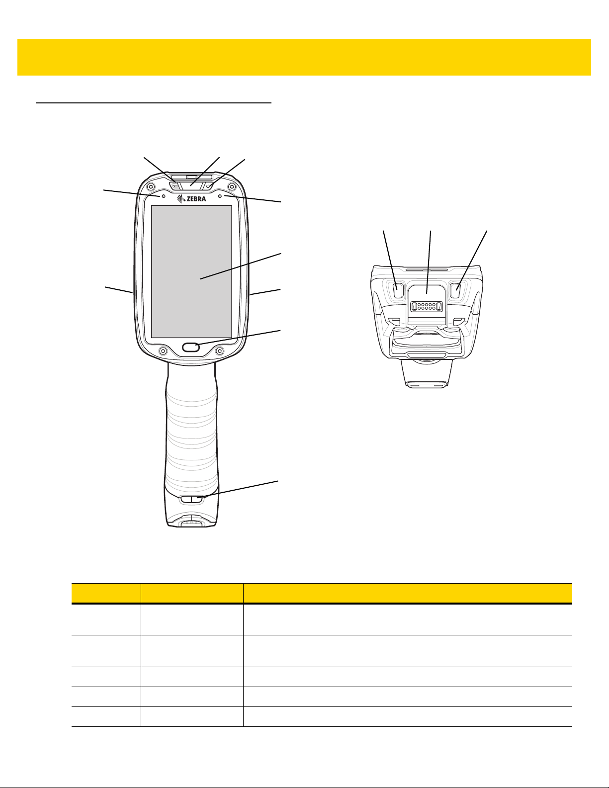
Features
Figure 1-1 Front View
Table 1-1 Front Vi
Number Item Function
ew Descriptions
1 Charging/Scan LED Indicates battery charging status while charging, good decode indication
during data capture and application generated notifications.
2 Power Button Turns the display on and off. Press and hold to reset the device an d power
off.
3 Blue Indication
LED User programmable LED.
4 Display Displays all information needed to operate the TC8000.
5 Touch Button Press to select items.
Page 21
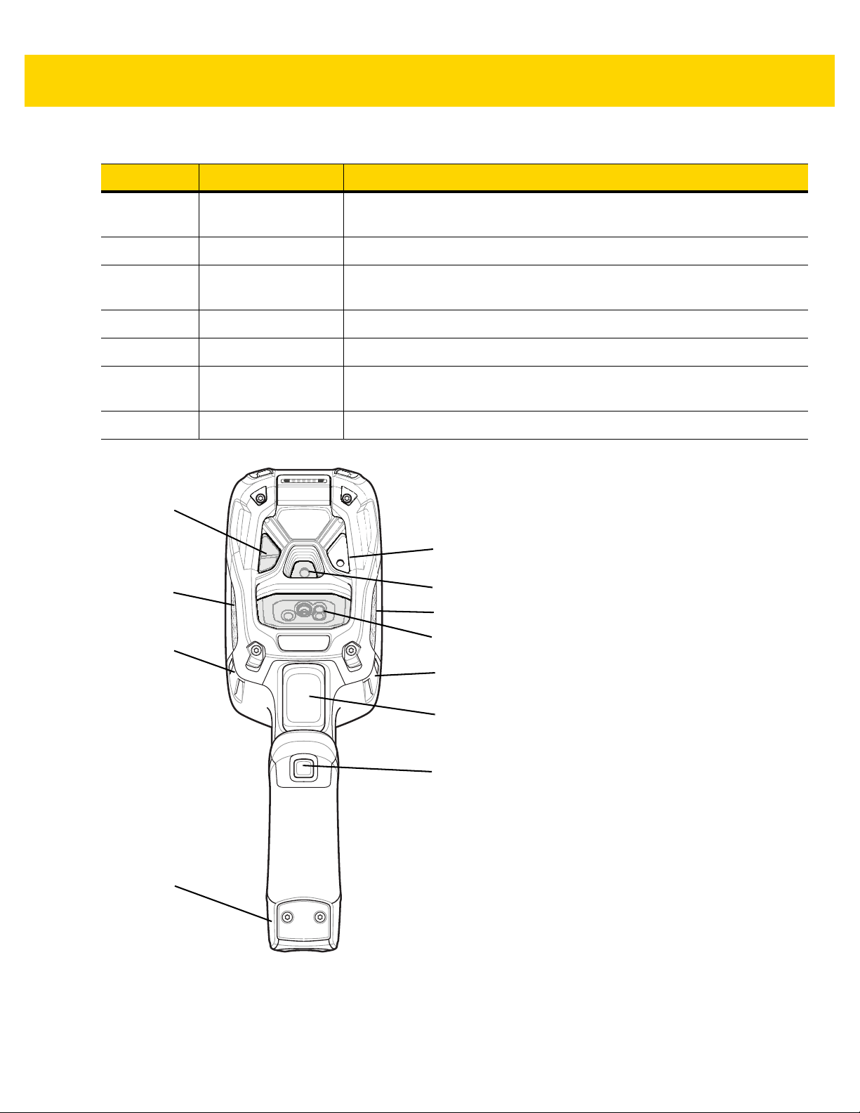
Table 1-1 Front View Descriptions (Continued)
1
2
4
5
7
8
9
6
3
3
8
Number Item Function
Getting Started 1 - 3
6 Hand Strap Mounting
Use for installing the optional hand strap.
Point
7 Speakers Provides audio output for video and music playback.
8 Ambient Light Sensor Determines ambient light for controlling display backlight intensity
(optional).
9 Micr
ophone Use for communication in Headset mode.
10 Volume Up Button Increases audio volume (programmable).
11 Interface Connector Provides USB host and client communication, audio and device charging
via cables
and accessories.
12 Volume Down Button Decreases audio volume (programmable).
Figure 1-2 Back View
Page 22

1 - 4 TC8000 Integrator Guide
Table 1-2 Back View Descriptions
Number Item Function
1 Camera Flash Provides illumination for the camera (optional).
2 Camera Takes photos and videos (optional).
3 Speaker Provides audio output.
4 Scanner Provides data capture using the imager or laser scanner.
5 Trigger Initiates data capture (programmable).
6 Push-To-Talk (PTT)
Button
7 Battery Pack Provides power to the device.
8 Hand Strap Mounting
Point
9 Proximity Sensor Long range proximity sensor (optional).
Setup
Perform these procedures to start using the TC8000 for the first time.
1. Install a micro secure digital (SD) card (optional).
2. Install the battery.
3. Charge the TC80 00.
4. Power on the TC8000.
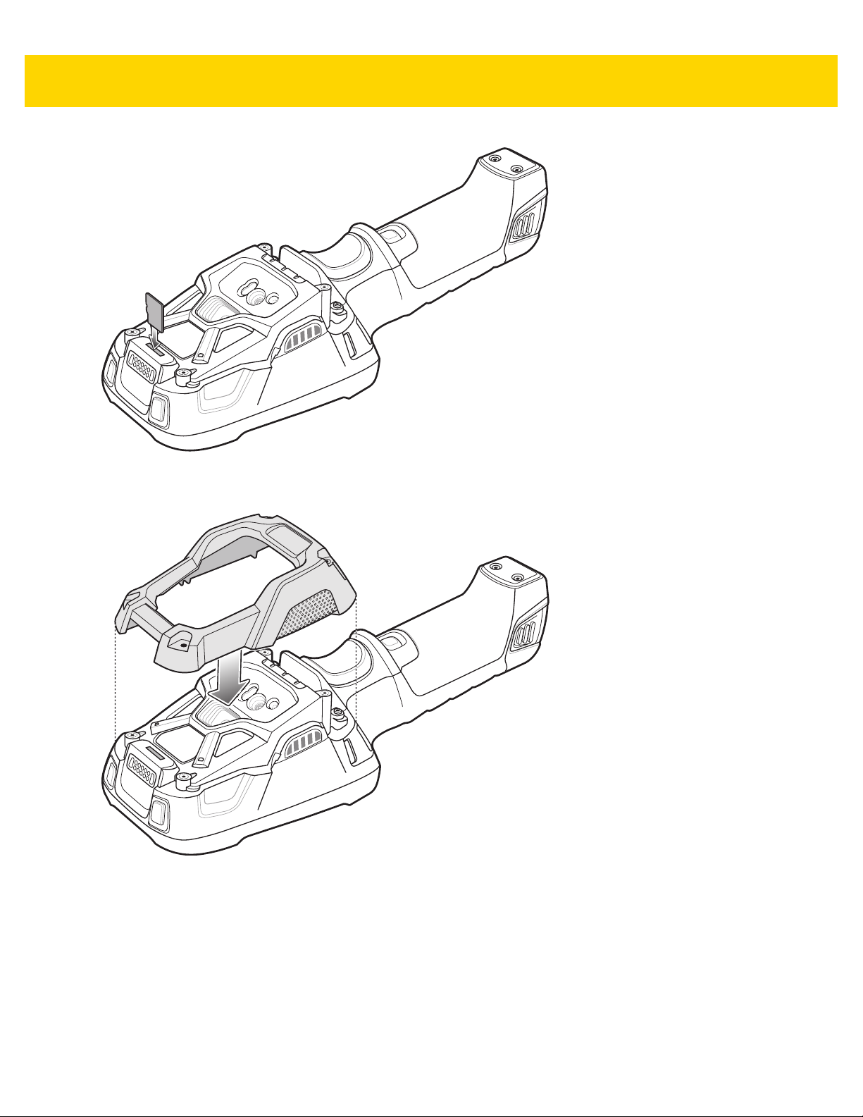
Installing the microSD Card
The microSD card slot provides secondary non-volatile storage. The slot is located under the back bezel of the
unit. Refer to the documentation provided with the card for more infor m at ion , an d fo llo w th e ma n ufa ct ur er 's
recommendations for use.
Initiates Push-To-Talk communication (programmable).
Use for installing the optional hand strap.
WARNING
NOTE
1. Remove the Torx T8 screws holding the back bezel in place.
!
Follow proper electrostatic discharge (ESD) precautions to avoid damaging the microSD card.
Proper ESD precautions include, but are not limite d to, working on an ESD mat and ens uring that
the operator is properly grounded.
Remove back bezel only in a dry location.
The Condensation Resistant configuration has six screws securing the back bezel.
When installing a microSD card on Condensation Resistant configurations, replac
desiccant pack. See Condensation Resistant Rear Bezel Replacement on page 2-49. Once the Rear Bezel is
removed, the desiccant pack absorbs ambient moisture and can lessen the life of the desiccant pack.
e the Back Bezel with
Page 23
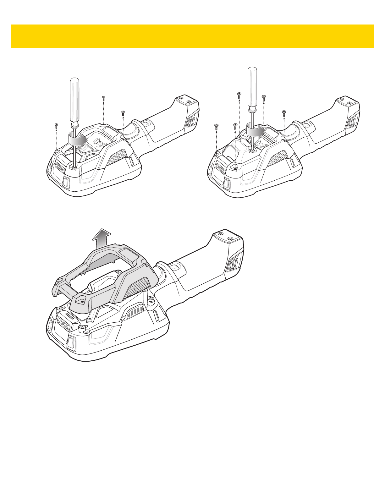
Figure 1-3 Remove Screws
2. Lift the bezel to expose the SD slot.
Getting Started 1 - 5
Figure 1-4 Remove Bezel
3. Insert the microSD card into the slot with contacts facing the bottom of the device.
Page 24
1 - 6 TC8000 Integrator Guide
Figure 1-5 Insert microSD Card
5. Align the back bezel onto the device.
Figure 1-6 Align Back Bezel
4. Tighten the four screws using T8 hex screwdriver.
5. Torque to 4.5 kg-cm.
Page 25
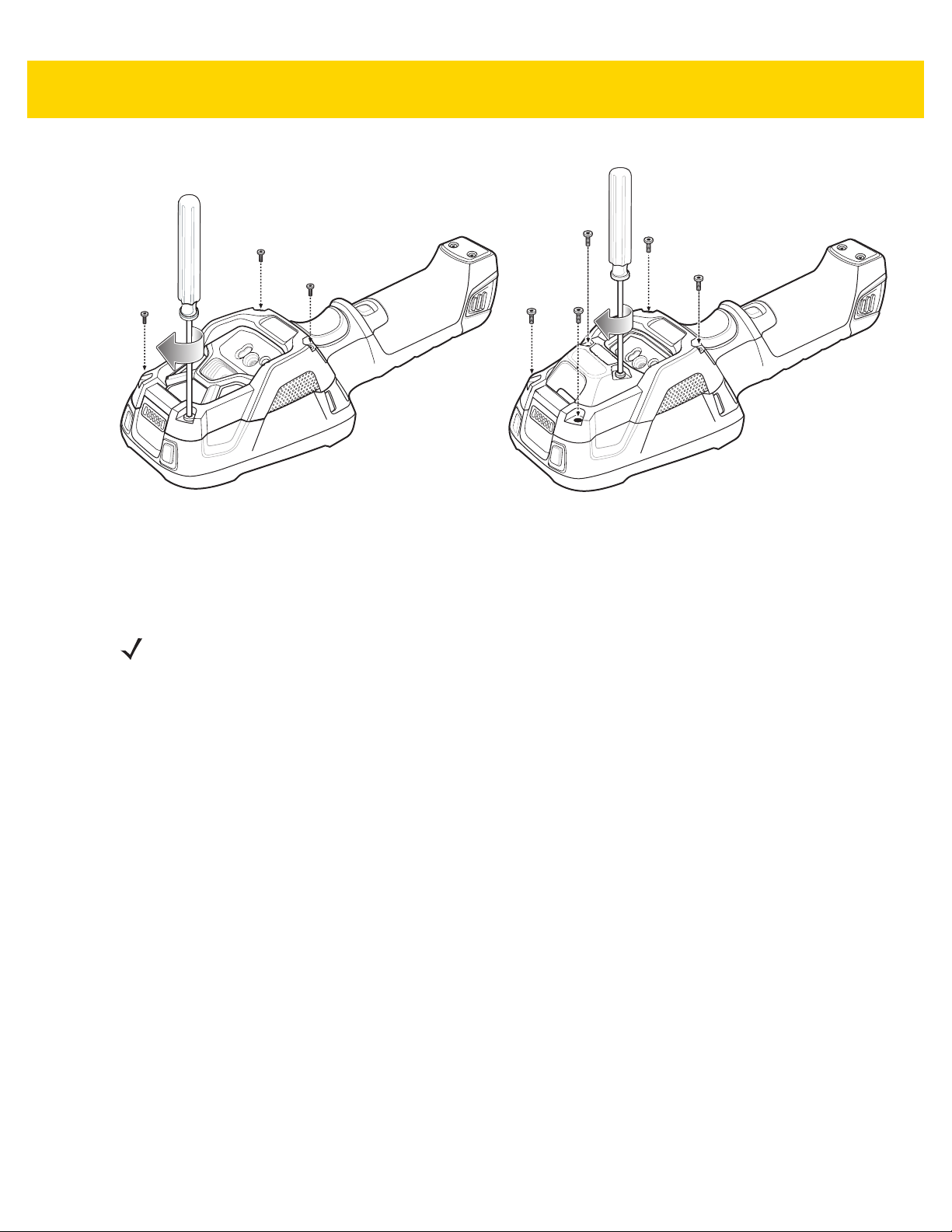
Figure 1-7 Secure Bezel
Getting Started 1 - 7
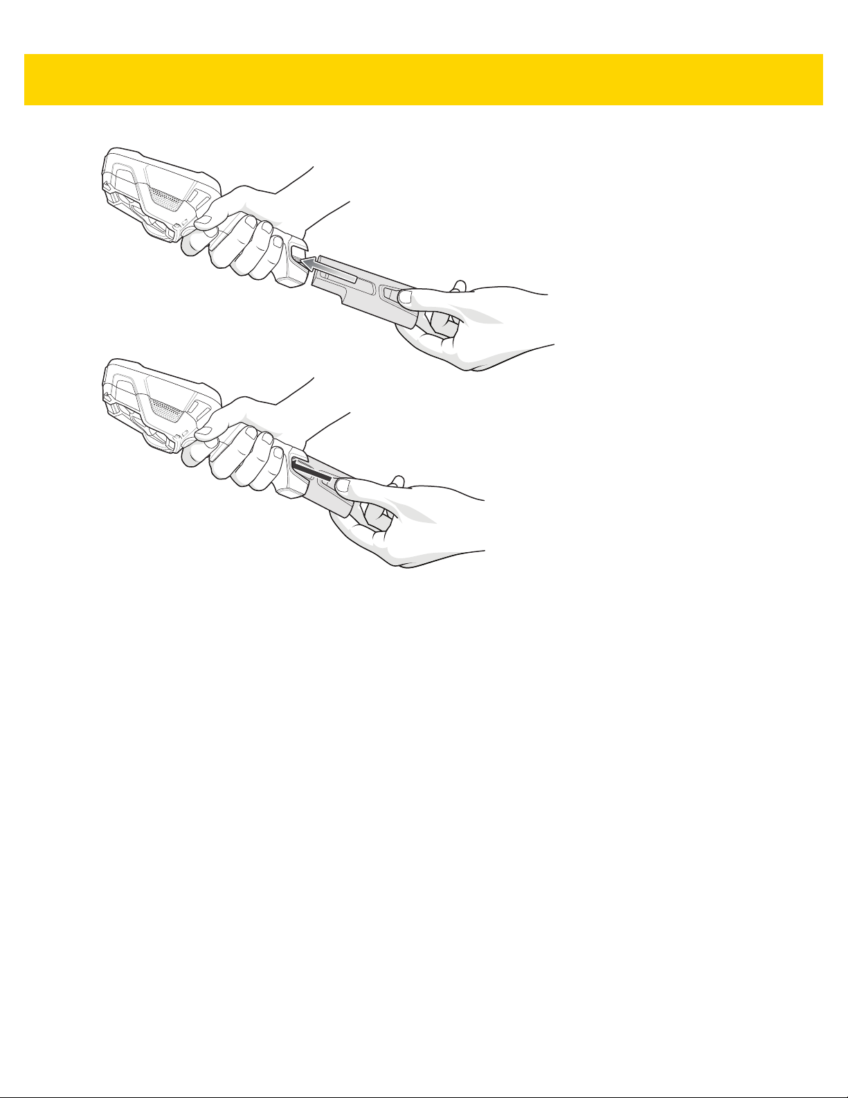
Installing the Battery
To install the battery:
NOTE
The battery is keyed to ensure that the battery is inserted properly. The notch in the battery must face the
back of the device.
1. Align the battery with the notch facing the back of the device.
2. Slide the battery into the handle of the device.
Page 26
1 - 8 TC8000 Integrator Guide
Figure 1-8 Battery Installation
3. Snap battery into place.
Charging the Battery
Before using the TC8000 for the first time, charge the battery using a cable or a cradle with the appropriate power
supply. For information about the accessories available for the TC8000 , see Chapter 2, Accessories.
The TC8000 is equipped with a supercapacitor (supercap) which automatically char
main battery. The supercap requires approximately 10 minutes to fully charge. The supercap retains random
access memory (RAM) data in memory and WLAN connection for at least 30 seconds when the main battery is
removed during Hot Swap. After 30 seconds, the WLAN connection is dropped and the RAM da ta is retained for 20
minutes.
•
4-Slot Battery Charger
•
2-Slot USB Charge Cradle
•
5-Slot Charge Only Cradle
•
5-Slot Ethernet Cradle
•
5-Slot Charge Only Cradle with 4-Slot Battery Charger
•
5-Slot Charge Only Cradle with 4-Slot Battery Charger.
ges from the fully-charged
The 6,700 mAh battery fully charges in approximately six h ours at room temperature.
Charge batteries in temperatures from 0 °C to 40 °C (32 °F to 104 °
battery charging in a safe and intelligent manner. At higher temperatures (e.g. approximately +37 °C (+98 °F)) the
F). The TC8000 or accessory alwa ys pe rfor ms
Page 27

Getting Started 1 - 9
TC8000 or accessory may for small periods of time alternately enable and disable battery charging to keep the
battery at acceptable temperatures. The TC8000 or accessory indicates when charging is disabled due to
abnormal temperatures via its LED.
1. To charge the main battery, connect the charging accessory to the appropriate power source.
2. Insert the TC8000 into a cradle or attach to a cable. The TC8000 turns on and begins charging. The
Charging/Notification LED blinks amber while charging, then turns solid green when fully charged.
Table 1-3 Charging/Scan LED Charging Indicators
State Indication
Off TC8000 is not charging. TC8000 is not inserted correctly in the cr adle or connec ted
to a power source. Charger/cradle is not powered.
Solid Amber Healthy battery is charging.
Solid Green Healthy battery charging is complete.
Fast Blinking Red
(2 blinks/second)
Charging error, e.g.:
- Temperature is too low or too high.
- Charging has gone on too long without completion (typically eight hours).
Solid Red Unhealthy battery is charging or fully charged.
IMPORTANT
When trying to power on the device, a quick blink of the charging LED indicates that it does not have
enough battery power to turn on. You will need to charge the battery or replace it.
Starting the TC8000
When installed in a cradle, the TC8000 starts automatically as soon as power is applied.
When a charged battery is installed and the TC8000 is turned off, press the Power button to turn on.
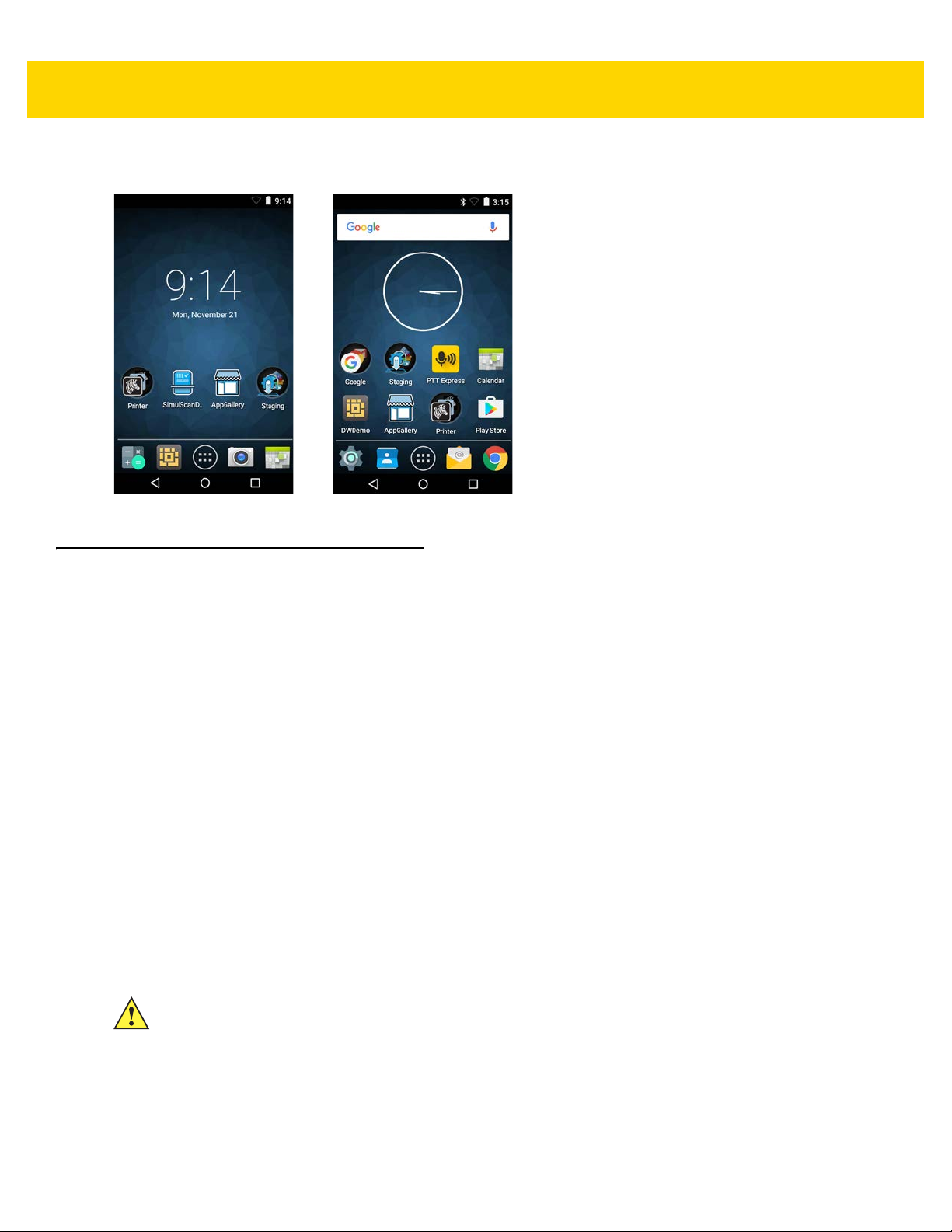
When the TC8000 is powered on for the first time, it initializes its system. The splas
period of time.
h screen appears for a short
Figure 1-9 Splash Screen
Page 28
1 - 10 TC8000 Integrator Guide
The splash screen is followed by the boot animation screen and then the Home Screen.
Figure 1-10 Home Screen - Non-GMS and GMS
Resetting the TC8000
There are four reset functions:
•
Soft reset
•
Hard reset
•
Enterprise reset
•
Factory reset.
Performing a Soft Reset
Perform a soft reset if applications stop responding.
1. Pre ss the po we r bu tt on unt il the m en u app ea rs .
2. Touch Reboot.
3. The device reboots.
Performing a Hard Reset
CAUTION
Perform a hard reset only if the TC8000 stops responding.
To perform a hard reset, simultaneously press and hold the power button, trigger and PTT button for five seconds.
When the device reboots, release the buttons and trigger.
Page 29

Getting Started 1 - 11
Performing an Enterprise Reset
An Enterprise Reset erases all data in the /cache and /data partitions and clears all device settings, except
those in the /enterprise partition.
Before performing an Enterprise Reset, copy all application
s and the key remap configuration file that you want to
persist after the reset into the /enterprise/usr/persist folder.
1. Download the Enterprise Reset file from the Zebra Support & Downloads web site.
2. Copy the Enterprise Reset zip file (T8KN0LXXVREXX02206.zip for AOSP or
T8KN0LXXAREXX02206.zip for GMS
) file to the root of the microSD card or the root of the Internal
Storage. See Chapter 3, USB Communication.
3. Press and hold the Power button until the menu appears.
4. Touch Power off.
5. Touch OK. The device turns off.
6. Press and hold the Power button and the trigger.
7. When the Zebra splash screen appears, release the button and trigger.
The System Recovery Screen appears.
Figure 1-11 System Recovery Screen
8. Press the Up and Down Volume buttons to navigate to the apply update from SD card or apply update from
internal storage option.
9. Press the trigger.
10. Press the Up and Down Volume buttons to navigate to the Enterprise Reset zip file
(
T8KN0LXXVREXX02206.zip for AOSP or T8KN0LXXAREXX02206.zip for GMS).
11. Press the trigger. The Enterprise Reset occurs and then the device resets.
Performing a Factory Reset
A Factor y Re se t er ases all da ta in the /cache, /data and /enterprise partitions in internal storage and clears
all device settings. A Factory Reset returns the device to the last installed operating system image. To revert to a
Page 30

1 - 12 TC8000 Integrator Guide
previous operating system version, re-install that operating system image. See System Update on page 6-6 for
more information.
1. Download the Factor y Reset file from the Zebra Support & Downloads web site.
2. Copy the Factory Reset zip file (T8KN0LXXVRFXX02206.zip for AOSP or
T8KN0LXXARFXX02206.zip for GMS)
Chapter 3, USB Communication.
3. Press and hold the Power button until the menu appears.
4. Touch Power off.
5. Touch OK. The device turns off.
6. Press and hold the Power button and the trigger.
7. When the Zebra splash screen appears, release the button and trigger.
The System Recovery Screen appears.
to the root of the microSD card or the root of Internal Storage. See
Figure 1-12 System Recovery Screen
8. Press the Up and Down volume buttons to navigate to the apply update from SD card or apply update from
internal storage option.
9. Press the trigger.
10. Press the Up and Down Volume buttons to navigate to the Factory Reset zip file
(
T8KN0LXXVRFXX02206.zip for AOSP or T8KN0LXXARFXX02206.zip for GMS).
11. Press the trigger. The Factory Reset occurs and then the device resets.
Page 31

CHAPTER 2 ACCESSORIES
Introduction
The TC8000 accessories provide a variety of product support capabilities. Table 2-1 lists the accessories available.
er
ies
communication with a host computer. Use with power
supply, p/n PWRS-14000-148R and country specific
grounded AC line cord.
ply
/
sup
50-16002-029R and country specific grounded AC line
cord.
commu
supply, p/n PWRS-14000-241R, DC line cord, p/n
50-16002-029R and country specific grounded AC line
cord.
CRD-TC8X-5SC4BC-01 Charges up to four TC8000 devices and four spare
batteries. Use with power supply, p/n
PWRS-14000-241R, DC line cord, p/n 50-16002-029R
and country specific grounded AC line cord.
n PWRS-14000-241R, DC line cord, p/n
, p
nication for
up to five devices. Use with power
Table 2-1 Accessor
Accessory Part Number Description
Cradles
2-Slot USB Charge Cradle CRD-TC8X-2SUCHG-01 Provides device and spare battery charging and USB
5-Slot Charge Only Cradle CRD-TC8X-5SCHG-01 Charges up to five TC8000 devices. Use with power
5-Slot Ethernet Cradle CRD-TC8X-5SETH-01 Provides device charging and provides Ethernet
5-Slot Charge Only Cradle
h Battery Charg
wit
5-Slot Ethernet Cradle
h Battery Charg
wit
er
CRD-TC8X-5SE4BC-01 Provides device charging and provides Ethernet
communication for up to four devices. Provides charging
for four spare batteries. Use with power supply, p/n
PWRS-14000-241R, DC line cord, p/n 50-16002-029R
and country specific grounded AC line cord.
Page 32

2 - 2 TC8000 Integrator Guide
Table 2-1 Accessories (Continued)
Accessory Part Number Description
Batteries and Chargers
Battery BTRY-TC8X-67MA1-01
BTRY-TC8X-67MA1-10
4-Slot Battery Charger SAC-TC8X-4SCHG-01 Charges up to four spare batteries. Requires power
USB and Charging Cable CBL-TC8X-USBCHG-01 Provides USB communication and power to the device.
Audio Accessories
Quick Disconnect Audio
Cable
3.5 mm Audio Cable CBL-TC8X-AUDBJ-01 Snaps onto the device and provides audio to a wired
Mounting Brackets
2-Slot Cradle Desktop
Stand
5-Slot Cradle Desktop
Stand
CBL-TC8X-AUDQD-01 Snaps onto the device and provides audio to a wired
BRKT-SCRD-SSDK-01 Use for mounting a 2-Slot cradle on a desk.
-SCRD-MSDK-01 Use for mounting a 5-Slot cradle on a desk or rack.
BRKT
Replacement battery (single pack).
Replacement battery (10–pack).
supply, p/
grounded AC line cord.
Requires power supply
specific un-grounded AC line cord.
headset with Quick Disconnect connector.
headset with 3.5 mm plu
n PWRS-14000-148R and country specific
PWRS-14000-249R and country
g.
Rack Mount Bracket BRKT-SCRD-SMRK-01 Use for mounting a 5-Slot cradle or four 4-Slot Battery
Chargers on a rac
Desktop Stand MNT-TC8X-DKPH-01 Un-powered desktop presentation stand. Allows to use
the device on a flat s
scanning.
Cart Mount MNT-TC8X-CMKT-01 Un-powered cart mount. Allows to install the device on
carts with up to 2”
device on hands-free scanning mode. Includes: Includes
RAM Mount required for installation.
Forklift Mount MNT-TC8X-FMKT-01 Un-powered forklift mount. Allows to install the de vice on
oll bar or square
a r
the device on landscape or portrait mode.
Carrying Solutions
Hand Strap SG-TC8X-HDSTP-01 Replacement hand strap.
Wrist Lanyard 50-12500-066 Optional lanyard for holding the device.
Quick Draw Soft Holster SG-TC8X-QDHLST-01 Use to hold the device. Requires the Universal Belt.
Presentation Soft Holster SG-TC8X-PMHLST-01 Use to hold the device and for hands-free scanning.
Requires the Univ
k.
urface (i.e. desktop) for hands-free
diameter rail/bar and allows to use the
surface of a forklift and allows to use
ersal Shoulder Strap or Universal Belt.
Page 33

Accessories 2 - 3
Table 2-1 Accessories (Continued)
Accessory Part Number Description
Universal Belt 11-08062-02R Use to hold the Quick Draw Soft Holster or the
Presentation Soft Holster.
Universal Shoulder Strap WA6010 Use to hold the Presentation Soft Holster.
Power Supplies
Power Supply PWRS-14000-249R Provides power to the device using the USB and
Charging Cable. Requires country specific un-grounded
AC line cord.
Power Supply PWRS-14000-148R Provides power to the 2–Slot cradles and 4-Slot Spare
Battery Charge
line cord.
Power Supply PWRS-14000-241R Provides power to the 5-Slot Charge Only Cradle, 5-Slot
Ethernet Cradle, 5Charger and the 5-Slot Ethernet Cradle with Battery
Charger. Requires DC Line Cord, p/n 50-16002–029R
and country specific grounded AC line cord.
r. Requires country specific grounded AC
Slot Charge Only Cradle with Battery
DC Y Cable 25-85993-01R Provides power from the PWRS-14000-241R power
supply to two
DC Line Cord 5
Miscellaneous
Stylus SG-TC7X-STYLUS-03 Stylus for use with the device (3-pack).
Screen Protectors MISC-TC8X-SCRN-01 Provides additional protection for display (5-pack).
Replacement
Condensation Resistant
Back Housing
0-16002-029R Provides power from the power supply to the 5-Slot
Charge Only Crad
Charge Only Cradle with Battery Charge and 5-Slot
Ethernet Cradle with Battery Charger.
MISC-TC8X-DSCNT-01 Field replaceable desiccant cartridge for condensation
resistant TC8000 models.
4-Slot Battery Chargers.
le, 5-Slot Ethernet Cradle, 5-Slot
Page 34

2 - 4 TC8000 Integrator Guide
Spare Battery Charging LED
Power LED
2-Slot USB Charge Cradle
CAUTION Ensure that you follow the guidelines for battery safety described in Battery Safety Guidelines on page 7-1.
The 2-Slot USB Charge Cradle:
•
Provides 5 VDC (nominal) power for operating the TC8000.
•
Provide USB communication with a host computer.
•
Charges the TC8000’s battery.
•
Charges a spare battery.
Figure 2-1 2-Slot Charge Only Cradle (Shown on Optional Desk Mount)
Page 35

Setup
AC Line Cord
Power Supply
USB Cable
Accessories 2 - 5
Figure 2-2 Setup (Shown on Optional Desk Mount)
Charging the Device
To charge a device:
1. Insert the TC8000 into the slot to begin charging.
Figure 2-3 Insert TC8000 into Cradle
2. Ensure the TC8000 is seated properly.
Page 36

2 - 6 TC8000 Integrator Guide
Charging the Spare Battery
To charge a spare battery:
1. Insert the battery into the right slot to begin charging.
2. Ensure the battery is seated properly.
Battery Charging
Main Battery Charging
The TC8000’s Charging/Notification LED indicates the status of the battery charging in the TC8000. The 6,700
mAh battery fully charges in less than four hours at room temperature.
Spare Battery Charging
The Spare battery Charging LED on the cup indicates the status of the spare battery charging. The 6,700 mAh
battery fully charges in less than four hours at room temperature.
Table 2-2 Spare Batter
State Indication
Off The battery is not charging. The battery is not inserted correctly in the cradle or
Solid Amber Healthy battery is charging.
Solid Green Healthy battery charging is complete.
Fast Blinking Red
(2 blinks/second)
Solid Red Unhealthy battery is charging or fully charged.
y Charging LED Indicators
connected to a power source. Cradle is not powered.
Charging error, e.g.:
- Temperature is too low or too high.
- Charging has gone on too long without completion (typically eight hours).
Charging Temperature
Charge batteries in temperatures from 0 °C to 40 °C (32 °F to 104 °F). The TC8000 or cradle always performs
battery charging in a safe and intelligent manner. At higher temperatures (e.g. approximately +37 °C (+98 °F)) the
TC8000 or cradle may for small periods of time alternately en able and disable battery charging to keep the battery
at acceptable temperatures. The TC8000 and cradle indicates when charging is disabled due to abnormal
temperatures via its LED.
Page 37

Accessories 2 - 7
Power LED
5-Slot Charge Only Cradle
CAUTION Ensure that you follow the guidelines for battery safety described in Battery Safety Guidelines on page 7-1.
The 5-Slot Charge Only Cradle:
•
Provides 5 VDC (nominal) power for operating the TC8000.
•
Simultaneously charges up to five TC8000s.
Figure 2-4 5-Slot Charge Only Cradle (Shown on Optional Desk Mount)
Page 38

2 - 8 TC8000 Integrator Guide
DC Line Cord
Power Supply
AC Line Cord
Setup
Figure 2-5 5-Slot Charge Only Cradle Setup (Shown on Optional Desk Mount)
Charging the TC8000
1. Insert the TC8000 into a slot to begin charging.
Figure 2-6 Insert TC8000 into Cradle
2. Ensure the TC8000 is seated properly.
Page 39

Accessories 2 - 9
Battery Charging
Main Battery Charging
The TC8000’s Charging/Notification LED indicates the status of the battery charging in the TC8000. The
6,700 mAh battery fully charges in less than four hours at room temperature.
Charging Temperature
Charge batteries in temperatures from 0 °C to 40 °C (32 °F to 104 °F). The TC8000 always performs battery
charging in a safe and intelligent manner . At higher temperatures (e.g. approximately +37 °C (+98 °F)) the TC8000
may for small periods of time alternately enable and disable battery charging to keep the battery at acceptable
temperatures.
Page 40

2 - 10 TC8000 Integrator Guide
Spare Battery Charging LED (4)
Power LED
5-Slot Charge Only Cradle with Battery Charger
CAUTION Ensure that you follow the guidelines for battery safety described in Battery Safety Guidelines on page 7-1.
The 4-Slot Charge Only Cradle with Battery Charger:
•
Provides 5 VDC (nominal) power for operating the TC8000.
•
Simultaneously charges up to four TC8000s.
•
Charges up to four spare batteries.
Figure 2-7 5-Slot Charge Only Cradle with Battery Charger (Shown on Optional Desk Mount)
Page 41

Setup
DC Line Cord
Power Supply
AC Line Cord
Accessories 2 - 11
Figure 2-8 5-Slot Charge Only Cradle with Battery Charger Setup (Shown on Optional Desk Mount)
Charging the TC8000
1. Insert the TC8000 into a slot to begin charging.
Figure 2-9 Insert TC8000 into Cradle
2. Ensure the TC8000 is seated properly.
Page 42

2 - 12 TC8000 Integrator Guide
Battery Charging
Main Battery Charging
The TC8000’s Charging/Notification LED indicates the status of the battery charging in the TC8000. The 6,700
mAh battery fully charges in less than four hours at room temperature.
Spare Battery Charging
The Spare battery Charging LED on the cup indicates the status of the spare battery charging. The 6,700 mAh
battery fully charges in less than four hours at room temperature.
Table 2-3 Spare Batter
State Indication
Off The battery is not charging. The battery is not inserted correctly in the cradle or
Solid Amber Healthy battery is charging.
Solid Green Healthy battery charging is complete.
Fast Blinking Red
(2 blinks/second)
Solid Red Unhealthy battery is charging or fully charged.
y Charging LED Indicators
connected to a power source. Cradle is not powered.
Charging error, e.g.:
- Temperature is too low or too high.
- Charging has gone on too long without completion (typically eight hours).
Charging Temperature
Charge batteries in temperatures from 0 °C to 40 °C (32 °F to 104 °F). The TC8000 always performs battery
charging in a safe and intelligent manner . At higher temperatures (e.g. approximately +37 °C (+98 °F)) the TC8000
may for small periods of time alternately enable and disable battery charging to keep the battery at acceptable
temperatures.
Page 43

5-Slot Ethernet Cradle
100/10 LED
1000 LED
CAUTION Ensure that you follow the guidelines for battery safety described in Battery Safety Guidelines on page 7-1.
The 5-Slot Ethernet Cradle:
•
Provides 5.0 VDC (nominal) power for operating the TC8000.
•
Connects the TC8000 (up to five) to an Ethernet network.
•
Simultaneously charges up to five TC8000s.
Accessories 2 - 13
Figure 2-10 5-Slot Ethernet Cradle (Shown on Optional Desk Mount)
To setup the 5-Slot Ethernet cradle:
Page 44

DC Line Cord
Power Supply
AC Line Cord
Router
Ethernet Cable
Primary Port
2 - 14 TC8000 Integrator Guide
Figure 2-11 5-Slot Ethernet Cradle with Battery Charger Setup (Shown on Optional Desk Mount)
1. Connect the DC line cord to power supply.
2. Connect DC line cord to power input on cradle.
3. Connect Ethernet cable to Ethernet port 1 on cradle.
4. Connect other end of Ethernet cable to router port.
5. Connect the AC line cord to the power supply.
6. Plug the AC line cord into an AC outlet.
Charging the TC8000
To charge the TC8000:
1. Insert the TC8000 into a slot to begin charging.
Page 45

Figure 2-12 Insert TC8000 into Cradle
2. Ensure the TC8000 is seated properly.
Accessories 2 - 15
Battery Charging
Main Battery Charging
The TC8000’s Charging/Notification LED indicates the status of the battery charging in the TC8000. The
6,700 mAh battery fully charges in less than four hours at room temperature.
Charging Temperature
Charge batteries in temperatures from 0 °C to 40 °C (32 °F to 104 °F). The TC8000 or cradle always performs
battery charging in a safe and intelligent manner. At higher temperatures (e.g. approximately +37 °C (+98 °F)) the
TC8000 or cradle may for small periods of time alternately en able and disable battery charging to keep the battery
at acceptable temperatures. The TC8000 and cradle indicates when charging is disabled due to abnormal
temperatures via its LED.
Daisy-chaining Ethernet Cradles
Daisy-chain up to ten 5-Slot Ethernet cradles to connect several cradles to an Ethernet network. Use either a
straight or crossover cable. Daisy-chaining should not be attempted when the main Ethernet con nection to the first
cradle is 10 Mbps as throughput issues will almost certainly result.
To daisy-chain 5-Slot Ethernet cradles:
1. Connect power to each 5-Slot Ethernet Cradle with Battery Charger.
2. Connect an Ethernet cable to port 1 on the back of the first cradle and to the Ethernet switch.
3. Connect an Ethernet cable to port 2 on the back of the first cradle to port 1 on the back of the second cradle.
Page 46

DC Line Cord
(to Power Supply)
DC Line Cord
(to Power Supply)
Ethernet Cable
(to Next Cradle)
Primary Port Secondary Port
Primary Port
Secondary Port
2 - 16 TC8000 Integrator Guide
Figure 2-13 Daisy-Chaining 5-Slot Ethernet Cradles (Shown on Optional Desk Mount)
4. Connect additional cradles as described in step 2 and 3.
Ethernet Settings
The following settings can be configured when using Ethernet communication:
•
Proxy Settings
•
Static IP.
Configuring Ethernet Proxy Settings
A proxy server is a server that acts as an intermediary for requests from clients seeking resources from other
servers. A client connects to the proxy server, requesting some service, such as a file, connection, web page, or
other resource, available from a different server. The proxy server evaluates the request according to its filter ing
rules. For example, it may filter traffic by IP address or protocol. If the request is validated by the filter, the proxy
provides the resource by connecting to the relevant server and requesting the service on behalf of the client.
It is important for enterprise customers to be ab le to set up secu re computing environm ents within their companies,
nd proxy configur
a
ation is an essential part of doing that. Proxy configuration acts as a secur ity barrier ensuring
that the proxy server monitors all traffic between the Internet and the intranet. This is normally an integral part of
security enforcement in corporate firewalls within intranets.
1. Touch > > Ethernet.
2. Slide the switch to the ON position.
3. Touch > Advanced.
Page 47

Figure 2-14 Ethernet Proxy Settings
Accessories 2 - 17
4. Touch Enable HTTP Proxy.
5. In the Proxy hostname field, enter the proxy server address.
6. In the Proxy port field, enter the proxy server port number.
NOTE When entering proxy addresses in the Bypass proxy for field, do not use spaces or carriage returns
between addresses.
7. In the Bypass proxy for text box, enter addresses for web sites that do not require to go through the proxy
server. Use the separator “|” between addresses.
8. Touch Save.
9. Touch .
Configuring the Device to Use a Static IP Address
By default, the device is configured to use Dynamic Host Configuration Protocol (DHCP) to assign an Internet
protocol (IP) address when connecting to a wireless network. To configure the device to connect to a network using
a static IP address:
1. Touch > > Ethernet.
2. Slide the switch to the ON position.
3. Touch Config.
Page 48

2 - 18 TC8000 Integrator Guide
Figure 2-15 Configure Ethernet Device Settings
4. Under Connection Type, touch the Static IP radio button.
DHCP is the default Connection T
5. In the IP address field, enter the proxy server address.
6. If required, in the Netmask text box, enter the network mask addre ss.
7. If required, in the Gateway address text box, enter a gateway address for the device.
8. If required, in the DNS 1 address text box, enter a Domain Na me System (DNS) address.
9. Touch Save.
10. Touch .
ype.
LED Indicators
There are two green LEDs on the side of the cradle and o n each Ethernet port. These green L EDs light and blink to
indicate the data transfer rate.
Table 2-4 LED Data Rate Indicators
Data Rate 1000 LED 100/10 LED
1 Gbps On/Blink Off
100 Mbps Off On/Blink
10 Mbps Off On/Blink
Page 49

Establishing Ethernet Connection
1. Touch > > Ethernet.
2. Slide the Ethernet switch to the ON position.
3. Insert the device into a slot.
Accessories 2 - 19
The
4. Touch Eth0 to view Ethernet connection details.
icon appears in the Status bar.
Page 50

2 - 20 TC8000 Integrator Guide
Spare Battery Charging LED (4)
100/10 LED
1000 LED
5-Slot Ethernet Cradle with Battery Charger
CAUTION Ensure that you follow the guidelines for battery safety described in Battery Safety Guidelines on page 7-1.
The 5-Slot Ethernet Cradle with Battery Charger:
•
Provides 5.0 VDC (nominal) power for operating the TC8000.
•
Connects the TC8000 (up to five) to an Ethernet network.
•
Simultaneously charges up to four TC8000s.
•
Simultaneously charges up to four spare batteries.
Figure 2-16 5-Slot Ethernet Cradle with Battery Charger (Shown on Optional Desk Mount)
Page 51

Setup
DC Line Cord
Power Supply
AC Line Cord
Router
Ethernet Cable
Primary Port
To setup the 5-Slot Ethernet cradle:
Accessories 2 - 21
Charging the TC8000
Figure 2-17 5-Slot Ethernet Cradle with Battery Charger Setup (Shown on Optional Desk Mount)
1. Connect the DC line cord to power supply.
2. Connect DC line cord to power input on cradle.
3. Connect Ethernet cable to Ethernet port 1 on cradle.
4. Connect other end of Ethernet cable to router port.
5. Connect the AC line cord to the power supply.
6. Plug the AC line cord into an AC outlet.
To charge the TC8000:
1. Insert the TC8000 into a slot to begin charging.
Page 52

2 - 22 TC8000 Integrator Guide
Figure 2-18 Insert TC8000 into Cradle
2. Ensure the TC8000 is seated properly.
Battery Charging
Main Battery Charging
The TC8000’s Charging/Notification LED indicates the status of the battery charging in the TC8000. The
6,700 mAh battery fully charges in less than four hours at room temperature.
Spare Battery Charging
The Spare battery Charging LED on the cup indicates the status of the spare battery charging. The 6,700 mAh
battery fully charges in less than four hours at room temperature.
Table 2-5 Spare Battery Charging LED Indicators
State Indication
Off The battery is not charging. The battery is not inserted correctly in the cradle or
connected to a power source. Cradle is not powered.
Solid Amber Healthy battery is charging.
Solid Green Healthy battery charging is complete.
Fast Blinking Red
(2 blinks/second)
Charging error, e.g.:
- Temperature is too low or too high.
- Charging has gone on too long without completion (typically eight hours).
Solid Red Unhealthy battery is charging or fully charged.
Charging Temperature
Charge batteries in temperatures from 0 °C to 40 °C (32 °F to 104 °F). The TC8000 or cradle always performs
battery charging in a safe and intelligent manner. At higher temperatures (e.g. approximately +37 °C (+98 °F)) the
TC8000 or cradle may for small periods of time alternately en able and disable battery charging to keep the battery
Page 53

Accessories 2 - 23
at acceptable temperatures. The TC8000 and cradle indicates when charging is disabled due to abnormal
temperatures via its LED.
Daisy-chaining Ethernet Cradles
See Daisy-chaining Ethernet Cradles on page 2-15.
Ethernet Settings
See Ethernet Settings on page 2-16.
Establishing Ethernet Connection
1. Touch > > Ethernet.
2. Slide the Ethernet switch to the ON position.
3. Insert the device into a slot.
The
4. Touch Eth0 to view Ethernet connection details.
icon appears in the Status bar.
Page 54

2 - 24 TC8000 Integrator Guide
Spare Battery Charging LED (4)
Power Supply
AC Line Cord
4-Slot Battery Charger
This section describes how to use the 4-Slot Battery Charger to charge up to four TC8000 batteries.
Figure 2-19 4-Slot Battery Charger
Setup
Figure 2-20 Four Slot Battery Charger Power Setup
Page 55

Accessories 2 - 25
Charging Spare Batteries
1. Connect the charger to a power source.
2. Insert the battery into a battery charging well and gently press down on the battery to ensure proper contact.
The Spare Battery Charging LED on the cup indicates the status of the spare battery charging. The 6,700 mAh
battery fu
lly charges in less than four hours at room temperature.
Table 2-6 Spare Batter
State Indication
Off The battery is not charging. The battery is not inserted correctly in the cradle or
Solid Amber Healthy battery is charging.
Solid Green Healthy battery charging is complete.
Fast Blinking Red
(2 blinks/second)
Solid Red Unhealthy battery is charging or fully charged.
y Charging LED Indicators
connected to a power source. Cradle is not powered.
Charging error, e.g.:
- Temperature is too low or too high.
- Charging has gone on too long without completion (typically eight hours).
Charging Temperature
Charge batteries in temperatures from 0 °C to 40 °C (32 °F to 104 °F). The TC8000 or cradle always performs
battery charging in a safe and intelligent manner. At higher temperatures (e.g. approximately +37 °C (+98 °F)) the
TC8000 or cradle may for small periods of time alternately en able and disable battery charging to keep the battery
at acceptable temperatures. The TC8000 and cradle indicates when charging is disabled due to abnormal
temperatures via its LED.
Page 56

2 - 26 TC8000 Integrator Guide
Screws (4)
Plate
Feet (2)
2-Slot Desk Bracket
Use the 2-Slot Desk Mount to mount the 2-Slot USB Charging cradle in a vertical position.
Figure 2-21 2-Slot Desk Mount
Assembly
To assemble the 2-Slot Desk Mount:
1. Align plate mounting holes with holes in feet.
Figure 2-22 Install Feet
2. Secure plate to feet with four screws and four washers.
Mounting Cradle
To mount the cradle:
Page 57

1. Align mounting slots on bottom of cradle with studs on plate.
Studs (3)
Safety Screw
Figure 2-23 Install Cradle onto Desk Mount
Accessories 2 - 27
2. Secure cradle to plate using safety screw.
Figure 2-24 Install Safety Screw
Page 58
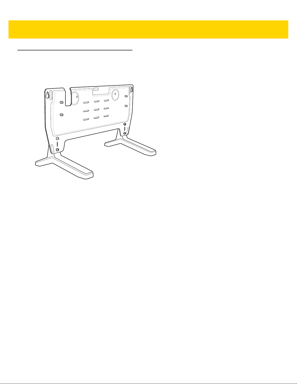
2 - 28 TC8000 Integrator Guide
5-Slot Desktop Bracket
Use the 5-Slot Desk Mount to mount the 5-Slot Charge Only cradles or the 5-Slot Ethernet cradles in a vertical
position.
Figure 2-25 5-Slot Desk Mount
Assembly
To assemble the 5-Slot Desk Mount:
1. Align plate mounting holes with holes in feet.
Page 59

Screws (4)
Plate
Feet (2)
Accessories 2 - 29
Studs (4)
Figure 2-26 Install Feet
2. Secure plate to feet with four screws and four washers.
Mount Cradle
To mount the cradle:
1. Align mounting slots on bottom of cradle with studs on plate.
Figure 2-27 Install Cradle onto Desk Mount
Page 60

2 - 30 TC8000 Integrator Guide
Safety Screws (2)
2. Secure cradle to plate using two safety screws.
Figure 2-28 Install Safety Screws
Page 61

Cart Mount
Use the Cart Mount to hold the TC8000 and perform hands-free scanning in Presentation Mode.
Accessories 2 - 31
Figure 2-29 Cart Mount
Installation
To assemble the Cart Mount and RAM Mount:
1. Secure the RAM Mount ball base to the bottom of the Cart Mount using four screws and four washers
(provided).
2. In se rt the so cke t arm to th e ba ll base an d cla w bas e.
3. Slightly tighten the knob on the socket arm.
Page 62

RAM Mount Ball Base
RAM Mount Socket Arm
RAM Mount Claw Base
RAM Mount Ball Base
2 - 32 TC8000 Integrator Guide
Figure 2-30 Cart Mount Assembly
4. Squeeze the claw base and install on a cart rail.
Page 63

Claw Knob
Socket Arm Knob
Accessories 2 - 33
Figure 2-31 Cart Mount Installation on Cart Rail
5. Position the Cart Mount and tighten the claw knob and socket arm knob.
6. Insert the TC8000 handle into the Cart Mount cradle and rotate into the cradle.
Page 64

2 - 34 TC8000 Integrator Guide
DC line Cord AC line CordPower Supply
Studs (4)
5-Slot Cradle Rack Installation
Use the Rack/Wall Mount Bracket to mount a 5-slot cradle on a rack. When installing on a rack, first assemble the
bracket and cradles/chargers and then install the assembly on the rack.
1. Place the power supply in bottom tray.
2. Connect AC line cord to power supply.
3. Connect DC line cord to power supply.
4. Secure power supply and cables to bottom tray with tie wraps.
NOTE Ensure tie wrap buckle is on side of power supply. Tie wrap buckle on top of power supply interferes with
top tray.
5. Route cables through cable slots.
Figure 2-32 Power Supply in Bottom Tray
6. Secure four M2.5 studs to top tray as shown.
Figure 2-33 Install Studs
7. Align and install 5-Slot cradle onto studs of top tray.
Page 65

Figure 2-34 Align Cradle on Studs
Safety Screws(2)
8. Secure cradle to top tray with two M2.5 safety screws.
Accessories 2 - 35
Figure 2-35 Secure Cradle
9. Slide top tray onto bottom tray.
Figure 2-36 Slide Top Trap onto Bottom Tray
Page 66

2 - 36 TC8000 Integrator Guide
10. Connect cables to cradle.
Figure 2-37 Connect Cables
11. Secure top tray to bottom tray with 4 M5 screws (two on each side).
Figure 2-38 Secure Top and Bottom Tray
See Rack Mount Installation on page 2-41 for installing the bracket assembly onto a rack.
Page 67

4-Slot Battery Chargers Rack Installation
DC Y Cable 2
AC line Cord 2
Power Supply 1
Power Supply 2
AC line Cord 1
DC Y Cable 1
Use the Rack/Wall Mount Bracket to mount four 4-Slot Battery Chargers on a rack. When installing on a rack, first
assemble the bracket and chargers and then install the assembly on the rack.
1. Place one power supply horizontally in bottom tray.
2. Place one power supply vertically in bottom tray.
3. Connect AC line cords to power supplies.
4. Connect DC line cords to power supplies.
5. Secure power supplies and cables to bottom tray with tie wraps.
6. Route cables through cable slots.
Accessories 2 - 37
Figure 2-39 Power Supplies in Bottom Tray
7. Slide top tray onto bottom tray until top tray touches vertical power supply.
Page 68

2 - 38 TC8000 Integrator Guide
Studs (16)
Figure 2-40 Slide top Tray onto Bottom Tray
8. Install 16 M2.5 studs onto top tray as shown below.
Figure 2-41 Install Studs
9. Align and install 4-Slot Battery Charger onto four studs.
Page 69

Figure 2-42 Align Chargers on Studs
10. Connect DC Y cables to four 4-Slot Battery Chargers.
Accessories 2 - 39
Figure 2-43 Connect Cables
11. Secure top tray to bottom tray with four M5 screws (two on each side).
Page 70

2 - 40 TC8000 Integrator Guide
Figure 2-44 Secure Top Tray to Bottom Tray
See Rack Mount Installation on page 2-41 for installing the bracket onto a rack.
Page 71
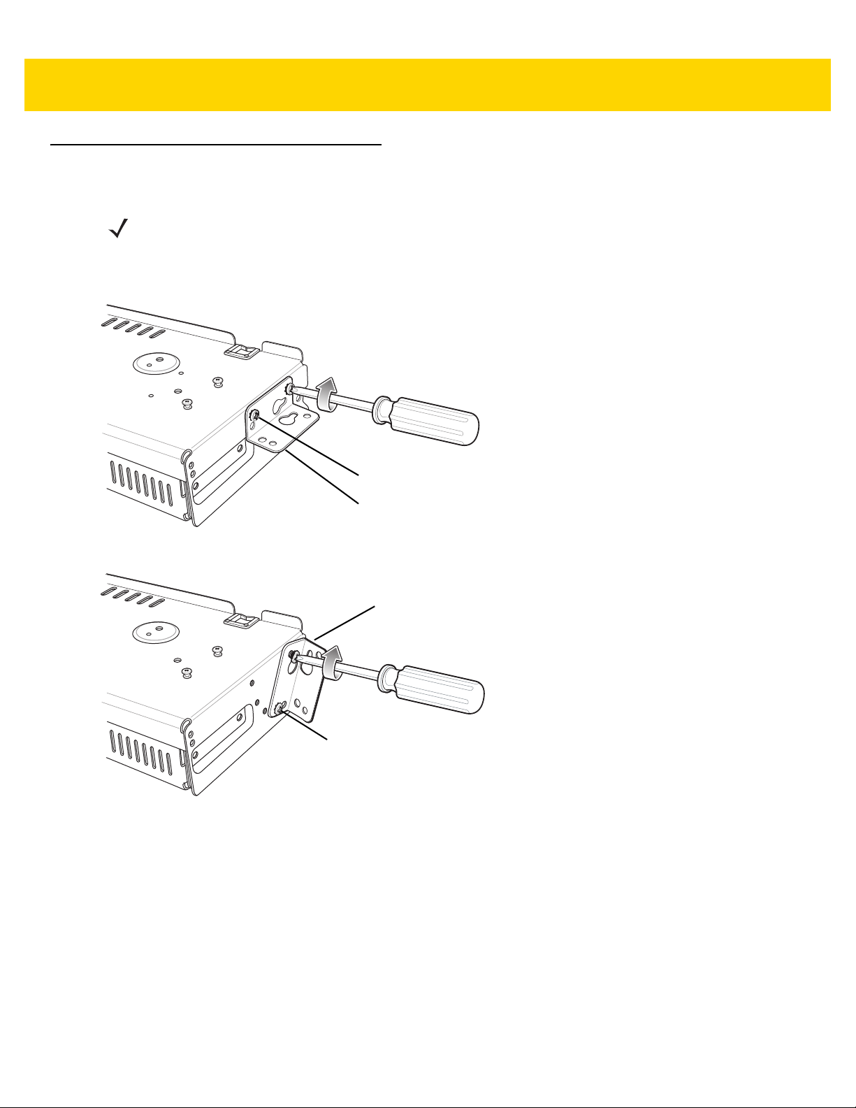
Rack Mount Installation
Top Screw Hole
Flange
Fourth Screw Hole
Flange
NOTE Use screws provided with rack system. Refer to rack user documentation for instructions.
1. Secure mounting brackets to both sides of top tray with four M5 screws (two on each side). For 5-Slot cradles,
position the flange for vertical installation. For 4-Slot Battery Chargers, position the flange for 25° installation.
Accessories 2 - 41
Figure 2-45 Flange Vertical Position (5-Slot Cradles)
Figure 2-46 Flange 25° Position (4-Slot Battery Chargers)
2. Install two rack sys tem screw s for top of mounting brackets. The screw heads should protrude half way from
the rail.
Page 72

Rack Screws
2 - 42 TC8000 Integrator Guide
Figure 2-47 Install Rack System Screws
3. Align the mounting bracket’s top mounting key holes with the screws.
4. Place the brackets on the screws.
Figure 2-48 Secure Bracket to Rack (Vertical Position Shown)
5. Secure the top screws.
6. Install bottom screws and tighten screws.
7. Route cables and connect to power source.
CAUTION Installer should ensure that all building codes are followed when connecting the power supplies to an
AC power source.
While installing the brackets, power supplies and cables:
Page 73

•
Use tie wraps to secure cables to the bracket and rails.
•
Coil cables wherever possible.
•
Route power cables along the rails.
•
Route inter-cradle cables to the side rails and then from the rails to the bracket.
Accessories 2 - 43
Page 74

2 - 44 TC8000 Integrator Guide
406 mm
137.8 mm
5-Slot Cradle Wall Installation
Use the Rack/Wall Mount Bracket to mount a cradle on a wall. When installing on a wall, first assemble the bottom
tray, install the bottom tray on the wall and then assemble the top tray.
Use mounting hardware (screws and/or anchors) appropriate for the type of wall mounting the bracket onto. The
Mount Bracke
(44 lbs.)
t mounting slots dimensions are 5 mm (0.2 in.). Fasteners must be able to hold a minimum of 20 Kg
For proper installation consult a professional installer. Failure to install the bracket
damage to the hardware.
properly can possibly result in
Bottom Tray Assembly
See steps 1 through 5 on page 34 for instructions.
Bracket Wall Mounting
1. Drill holes and install anchors according to the template supplied with the bracket.
2. Install two screws for bottom of bracket. The screw heads should protrude 2.5 mm (0.01”) from the wall.
Figure 2-49 Vertical Wall Mounting Dimensions
3. Align the mounting bracket’s bottom mounting key holes with the screws.
4. Hang the bracket on the screws.
Page 75
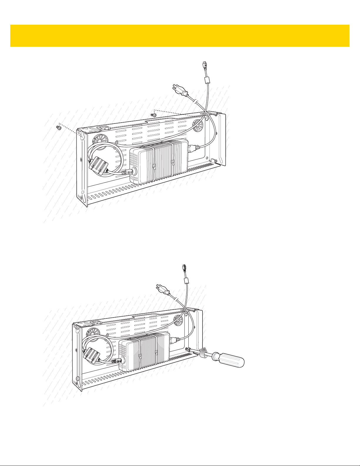
Accessories 2 - 45
Figure 2-50 Vertical Installation
5. Install two top screw s.
6. Tighten all screws.
Figure 2-51 Horizontal Installation - Tighten Screws
7. Assembly the top tray. See steps 6 through 8 on page 34.
8. Slide the assembled top tray onto bottom tray.
Page 76

2 - 46 TC8000 Integrator Guide
9. Connect cables to cradle.
10. Secure top tray to bottom tray with four M5 screws (two on each side).
11. Route cables and connect to power source.
CAUTION Installer should ensure that all building codes are followed when connecting the power supplies to an
AC power source.
While installing the brackets, power supplies and cables:
•
Use tie wraps to secure cables to the bracket.
•
Coil cables wherever possible.
•
Route power cables along wall and secure.
Page 77

4-Slot Battery Charger Wall Installation
22.85 mm
398 mm
Use the Rack/Wall Mount Bracket to mount four 4-Slot Battery Chargers a cradle on a wall. When installing on a
wall, first assemble the bottom tray, install the bottom tray on the wall and then assemble the top tray.
Use mounting hardware (screws and/or anchors) appropriate for the type of wall mounting the bracket onto. The
Mount Bracke
(44 lbs.)
t mounting slots dimensions are 5 mm (0.2 in.). Fasteners must be able to hold a minimum of 20 Kg
Accessories 2 - 47
For proper installation consult a professional installer. Failure to install the bracket
damage to the hardware.
properly can possibly result in
Bottom Tray Assembly
See steps 1 through 5 on page 37 for instructions.
Bracket Wall Mounting
1. Drill holes and install anchors according to the template supplied with the bracket.
2. Install two screws for bottom of bracket. The screw heads should protrude 2.5 mm (0.01”) from the wall.
Figure 2-52 Horizontal Mounting Template
3. Align the mounting bracket’s bottom mounting key holes with the screws.
4. Hang the bracket on the screws.
Page 78

2 - 48 TC8000 Integrator Guide
Figure 2-53 Horizontal Installation
5. Install two top screw s.
6. Tighten all screws.
Figure 2-54 Horizontal Installation - Tighten Screws
7. Assembly the four 4-Slot Battery Chargers onto the bracket. See steps 7 through 11 on page 37.
8. Route cables and connect to power source.
CAUTION Installer should ensure that all building codes are followed when connecting the power supplies to an
AC power source.
While installing the brackets, power supplies and cables:
•
Use tie wraps to secure cables to the bracket and rails.
•
Coil cables wherever possible.
•
Route power cables along the rails.
•
Route inter-cradle cables to the side rails and then from the rails to the bracket.
Page 79

Condensation Resistant Rear Bezel Replacement
The Condensation Resistant configurations contain a de siccant pack that must be replaced every five months. The
desiccant pack is part of the Back Bezel. Replacement Back Bezel with desiccant pack comes in a vacuum sealed
package. Do not open the package until instructed in the steps below. Install immediately after opening.
To replace the Back Bezel:
1. Remove six screws securing the Back Bezel.
Accessories 2 - 49
Figure 2-55 Remove Screws
2. Lift Rear Bezel.
Figure 2-56 Lift Rear Bezel
3. Cut the package open with scissors.
Page 80

2 - 50 TC8000 Integrator Guide
Figure 2-57 Open Vacuum Bag
4. Remove Rear Bezel from package.
5. Align Rear Bezel with device.
Figure 2-58 Align Back Bezel
6. Secure Rear Bezel using six screws with a torque requirement of 4.5±0.2 kgf.cm.
Page 81

1
6
4
3
5
2
Figure 2-59 Secure Back Bezel
Accessories 2 - 51
Page 82

2 - 52 TC8000 Integrator Guide
Page 83

CHAPTER 3 USB COMMUNICATION
This chapter provides information for transferring files between the device and a host computer.
Connecting to a Host Computer via USB
Connect the TC8000 to a host computer using the USB and Charging Cable to transfer files between the TC8000
and the host computer.
CAUTION
When connecting the TC8000 to a host computer, follow the host computer’s instructions for
connecting and disconnecting USB devices, to avoid damaging or corrupting files.
Connecting to the TC8000 as a Media Device
NOTE
Using Media Device, you can copy files to either the microUSB card or internal memory.
1. Connect the USB Charge cable to the TC8000 and then to the host computer.
Connected as a media device or Conn
2. If Connected as a camera appears, pull down the Notification shade and touch Connected as a camera and
then touch Media device (MTP).
3. On the host computer, open a file explorer application.
4. Locate the TC8000 as a portable device.
5. Open the SD card, Internal storage or Enterprise storage folder.
6. Copy or delete files as required.
ected as a camera appears on the Status bar.
Page 84

3 - 2 TC8000 Integrator Guide
Connecting to the TC8000 as a Camera
NOTE
Using Camera, you can copy files to internal memory.
1. Connect the USB and Charging cable to the TC8000 and then to the host computer.
Connected as a media device or Conn
2. If Connected as a media device appears, pull down the Notification shade and touch Connected as a media
ected as a camera or appears on the Status bar.
device and then touch Camera (PTP).
3. On the host computer, open a file explorer application.
4. Locate the TC8000 as a portable device.
5. Open the Internal storage folder.
6. Copy or delete photos as required.
Disconnect from the Host Computer
CAUTION
7. On the host computer, unmount the device.
8. Remove the USB and Charging Cable from the device.
Carefully follow the host computer’s instructions to unmount the device and disconnect USB devices
correctly to avoid losing information.
Page 85

CHAPTER 4 DATAWEDGE
CONFIGURATION
DataWedge Configuration
This chapter applies to DataWedge on Android devices. DataWedge is an application that reads data, processes
the data and sends the data to an application.
Basic Scanning
Scanning can be performed using either the laser scanner or imager.
To capture bar code data:
1. Ensure that an application is open on the TC8000 and a text field is in focus (text cursor in text field).
2. Aim the exit window at a bar code.
3. Pre ss the tr igg er butto n. Ensu re the re d sca n beam cove rs th e en tir e ba r cod e . The Charging/ Sca n LED
Indicators illuminate green and a beep sounds to indicate a successful decode.
Profiles
DataWedge is based on profiles and plug-ins. A profile contains information on how DataWedge should behave
with different applications.
Profile information consists of:
•
•
•
•
Using profiles, each application can have a specific DataWedge configurat
can have a profile which outputs scanned data in the required format when that application comes to the
Associated application
Input plug-in configurations
Output plug-in configurations
Process plug-in configurations.
ion. For example, each user application
Page 86

4 - 2 TC8000 Integrator Guide
foreground. DataWedge can be configured to process the same set of captured data differently based on the
requirements of each application.
DataWedge includes the following visible and hidden pre-configured
applications:
•
Visible profiles:
•Profile0 - created automatically the first
user created profiles associated with an application.
• Launcher - di
this profile when not required.
•DWDemo - provides supp
•
DataWedge has built-in configurations for RD Client, MSP Agent, MspUserAttributes, and RhoElements.
•
DataWedge disables scanning when the default camera application is i the foreground.
sables scanning when the Launcher is in foreground. Note: to save battery power, disable
ort for the DWDemo application.
time DataWedge runs. Generic profile used when ther e are no
profiles which support specific built-in
Profile0
Profile0 can be edited but cannot be associated with an application. That is, DataWedge allows manipulation of
plug-in settings for Profile0 but it does not allow assignment of a foreground application. This configuration allows
DataWedge to send output data to any foreground application ot her than applications associated with user-defined
profiles when Profile0 is enabled.
Profile0 can be disabled to allow DataWedge to only send output data to those applications which are associated
in user-defined profiles. For example, create a profile associating a specific application, disable Profile0 and then
scan. DataWedge only sends data to the application specified in the user-created profile. This adds additional
security to DataWedge enabling the sending of data only to specified applications.
Plug-ins
A plug-in is a software module utilized in DataWedge to extend its functionality to encompass technologies such as
bar code scanning. The plug-ins can be categorized into three types based on their operations:
•
Input Plug-ins
•
Output Plug-ins
•
Process Plug-ins.
Input Plug-ins
An Input Plug-in supports an input device, such as a bar code scanner contained in, or attached to the device.
DataWedge contains base plug-ins for these input devices.
•
Bar Code Scanner Input Plug-in – The Bar Code Scanner Input Plug-in is resp onsible for reading data from
the integrated bar code scanner and supports diff erent types of bar code reade rs including laser, imager and
internal camera. Raw data read from the bar code scanner can be processed or formatted using Process
Plug-ins as required. DataWedge has built-in feedback functionality for the bar code scanner to issue user
alerts. The feedback settings can be configured according to user requirement.
Output Plug-ins
Output Plug-ins are responsible for sending the data from Input Plug-ins to a foreground application on the device.
Page 87

DataWedge Configuration 4 - 3
•
Keystroke Output Plug-in – The Keystroke Output Plug-in collects and sends data received from the Input
Plug-in to the foreground applications by emulating keystrokes.
•
Intent Output Plug-in – The Intent Output Plug-in collects and sends data received from the Input Plug-ins
to foreground applications using the Android Intent mechanism.
•
IP Output Plug-in – The IP Output Plug-in collects and sends data received fr om the Input Plug-ins to a host
computer via a network connection. Captured data can be sent over an IP network to a specified IP address
and port using either TCP or UDP transport protocols.
Process Plug-ins
Process Plug-ins are used in DataWedge to manipulate the received data according to the requirement, befo r e
sending to the foreground application via the Output Plug-in.
•
Basic Data Formatting Process Plug-in– The Basic Data Formatting Plug-in allows DataWedge to add a
prefix and/or a suffix to the captured data before passing it to an Output Plug-in.
•
Advanced Data Formatting Process Plug-in – The Advanced Data Formatting Plug-in allows DataWedge
to apply rules (actions to be performed based on defined criteria) to the data received via an input plug-in
before passing it to an Output Plug-in.
Profiles Screen
To launch DataWedge, touch > DataWedge. By default, three profiles appear:
•
Profile0
•
Launcher
•
DWDemo.
Profile0 is the default profile and is used when no other profile can be applied.
Figure 4-1 DataWedge Profiles Screen
Profile names are color coded. Enabled profiles are white and disabled profiles are gray.
To configure a profile touch the profile name.
Page 88

4 - 4 TC8000 Integrator Guide
Profile Context Menu
Touch and hold a profile to open a context menu that allows additional actions to be performed on the selected
profile.
Figure 4-2 Profile Context Menu
The profile context menu allows the profile to be edited (same as just tapping on a profile), renamed or deleted.
Options Menu
Touch to open the options menu.
Figure 4-3 DataWedge Options Menu
The menu provides options to create a new profiles, access to general DataWedge settings and DataWedge
version information.
Disabling DataWedge
1. Touch > .
2. Touch > Settings.
3. Touch DataWedge enabled.
The blue check disappears from the checkbox indicating that DataWedge is disabled.
Page 89

DataWedge Configuration 4 - 5
Creating a New Profile
To create a profile:
1. Touch > .
2. Touch > New profile.
3. In the New profile dialog box, enter a name for the new profile. It is recommended that profile names be
unique and made up of only alpha-numeric characters (A-Z, a-z, 0-9) .
Figure 4-4 New Profile Name Dialog Box
4. Touch OK.
The new profile name appears in the DataWedge profile screen.
Profile Configuration
To configure the Profile0 or a user-created profile, touch the profile name.
Figure 4-5 Profile Configuration Screen
The configuration screen lists the following sections:
•
Profile enabled
Page 90

4 - 6 TC8000 Integrator Guide
•
Applications
•
Data Capture panel (DCP)
•
Barcode Input
•
Simulscan Input
•
Keystroke output
•
Intent Output
•
IP Output.
Associating Applications
Use Applications option to associate applications with this profile. User created profiles should be associated with
one or more applications and its activities.
1. Touch Associated apps. A list of applications/activities associated with the profile displays. Initially the list
does not contain any applications/activities.
Figure 4-6 Associated Apps Screen
2. Touch > New app/activity.
3. In the Select application screen, select the desired application from the list.
Page 91

DataWedge Configuration 4 - 7
Figure 4-7 Select Application Menu
4. In the Select activity menu, selecting the activity adds that application/activity combination to the associated
application list for that profile. Selecting * as the activity results in all activities within that application being
associated to the profile. During opera tion , Da taWedge tries to match the specific application/activity
combinations with the foreground application/activity before trying to match the general application/*
combinations.
Page 92

4 - 8 TC8000 Integrator Guide
Figure 4-8 Select Activity Menu
5. The selected applications/activites display for the profile.
Page 93

DataWedge Configuration 4 - 9
Figure 4-9 Selected Application/Activity
6. Touch .
Data Capture Plus
The Data Capture Plus (DCP) is a DataWedge feature that enab les the user to initiate data capture by touching an
area on the screen. A button or screen overlay acts like a scan button.
Page 94

DCP Button
4 - 10 TC8000 Integrator Guide
Figure 4-10 Data Capture Plus Dock Button
The DataWedge profile configuration screen allows the user to configure ho
the particular profile is enabled. The DCP is hidden by default. Enabling DCP option displays additional
configuration parameters.
w the DCP appears on the screen once
Page 95

DataWedge Configuration 4 - 11
Figure 4-11 Data Capture Plus Settings
•
Enable - Select to enable Data Capture Plus (default - disabled).
•
Dock button on - Select position of the button.
• Left or right - Allows user to
• Left only - Places the button o
• Right only - Places the button o
•
Start in - Select the initial DCP state.
• Fullscreen mode - DCP covers
• Button mode - DCP displays as a circular bu
• Button only mode - DCP displays as
mode.
•
Button highest position - Select the top of the range the user is allowed to move th e DCP, given as a
percent of the screen height (default - 0).
•
Button lowest position - Select the bottom of the range the user is allowed to move the DCP, given as a
percent of the screen height (default - 100).
•
Drag detect time - Select the time in milliseconds that the scanner waits before activating scanner. This
allows the user to drag the button without initiating scanner (default - 100 ms, maximum 1000 ms).
NOTE
The DCP does not appear if the scanner is disabled in the profile even though the Enabled option is set.
place the button on either the right or left edge of the screen.
n left edge of the screen.
n the right edge of the screen.
the whole screen.
tton on the screen and can be switched to fullscreen mode.
a circular button on the screen and cannot be switched to fullscr een
In Button mode, the user can place DCP in full screen mode by dragging the button over Fullscreen mode. The
overlay covers the screen.
Page 96

4 - 12 TC8000 Integrator Guide
Figure 4-12 Fullscreen Mode
Swipe down to return to button mode.
Bar Code Input
Use the Bar Code Input options to configure the Bar Code Scanner Input Plug-in for the profile.
Enabled
Enables or disables this plug-in. A check in the checkbox indicates that the plug-in is enabled.
Scanner Selection
Configures which scanning device to use for bar code data capture when the profile is active.
•
Auto - The software automatically selects the 2D Imager.
•
Camera Scanner - Scanning is performed using the camera.
•
2D Barcode Imager - Scanning is performed using the 2D Imager.
•
Bluetooth Scanner - Scanning is performed using the optional RS507 Hands-free Bluetooth scanner.
Decoders
Configures which bar code decoders are en ab le d or disa ble d. For bes t perfo rm a nc e dis ab l e all unne ce ssary
decoders.
Touch Decoders. The Barcode input screen appears.
enabled. By default the most commonly used decoders are enabled. The supported decoders are:
A check in the checkbox indicates th at the decoder is
Page 97

NOTE
DataWedge supports the decoders listed below but not all are validated on this device.
Touch to return to the previous screen.
DataWedge Configuration 4 - 13
Table 4-1 Supported De
coders
Symbology Bar Code Imager Camera RS507
Australian Postal Disabled
Aztec Enabled
Canadian Postal Disabled
Chinese 2 of 5 Disabled
Codabar Enabled
Code 11 Disabled
Code 128 Enabled
Code 39 Enabled
Code 93 Disabled
Composite AB Disabled
Composite C Disabled
Discrete 2 of 5 Disabled
Datamatrix Enabled
Disabled Disabled
Enabled Enabled
Disabled N/A
Disabled Disabled
Enabled Enabled
Disabled Disabled
Enabled Enabled
Enabled Enabled
Disabled Disabled
Disabled Disabled
Disabled Disabled
Disabled Disabled
Enabled Enabled
Dutch Postal Disabled
EAN13 Enabled
EAN8 Enabled
GS1 DataBar Enabled
GS1 DataBar Expanded Enabled
GS1 DataBar Limited Disabled
HAN XIN Disabled
Interleaved 2 of 5 Disabled
Japanese Postal Disabled
Korean 3of 5 Disabled
MAIL MARK Enabled
Matrix 2 of 5 Disabled
Maxicode Enabled
Disabled Disabled
Enabled Enabled
Enabled Enabled
Enabled Enabled
Enabled Enabled
Disabled Disabled
Disabled N/A
Disabled Disabled
Disabled Disabled
Disabled Disabled
Enabled N/A
Disabled Disabled
Enabled Enabled
Page 98

4 - 14 TC8000 Integrator Guide
Table 4-1 Supported Decoders (Continued )
Symbology Bar Code Imager Camera RS507
MicroPDF Disabled
MicroQR Disabled
MSI Disabled
PDF417 Enabled
QRCode Enabled
Decoder Signature Disabled
TLC39 Disabled
Trioptic 39 Disabled
UK Postal Disabled
UPCA Enabled
UPCE0 Enabled
UPCE1 Disabled
US4state Disabled
US4state FICS Disabled
US Planet Disabled
Disabled Disabled
Disabled Disabled
Disabled Disabled
Enabled Enabled
Enabled Enabled
Disabled Disabled
Disabled Disabled
Disabled Disabled
Disabled Disabled
Enabled Enabled
Enabled Enabled
Disabled Disabled
Disabled Disabled
Disabled Disabled
Disabled Disabled
US Postnet Disabled
Disabled Disabled
Decoder Params
Use Decode Params to configure individual decoder parameters.
Codabar
•
CLSI Editing - Enable this parameter to strip the start and stop characters and insert a space after the first,
fifth, and tenth characters of a 14-character Codabar symbol. Enable this feature if the host system requires
this data format (default - disabled).
•
Length1 - Use to set decode lengths (default - 6). See Decode Lengths on page 4-20 for more information.
•
Length2 - Use to set decode lengths (default - 55). See Decode Lengths on page 4-20 for more information.
•
NOTIS Editing - Enable this parameter to strip the start and stop characters from a decoded Codabar
symbol. Enable this feature if the host system requires this data format (default - disabled).
•
Redundancy - Sets the reader to read the bar code twice before accepting data. A check in the checkbox
indicates that redundancy is enabled (default - enabled).
Code 11
•
Length1 - Use to set decode lengths (default - 4). See Decode Lengths on page 4-20 for more information.
•
Length2 - Use to set decode lengths (default - 55). See Decode Lengths on page 4-20 for more information.
•
Redundancy - Sets the reader to read the bar code twice before accepting data. A check in the checkbox
indicates that redundancy is enabled (default - enabled).
Page 99

DataWedge Configuration 4 - 15
•
Report Check Digit - Transmit Code 11 data with or without the check digit. A check in the checkbox
indicates to send Code 11 data with check digit (default - disabled).
•
Verify Check Digit - Check the integrity of all Code 11 symbols to verify that the data complies with the
specified check digit algorithm. This selects the check digit mechanism for the decoded Code 11 bar code.
• No Check Digit - Do not verify check digit.
•
1 Check Digit - Bar code
• 2 Check Digits - Bar code
Code128
•
Code128 Reduced Quiet Zone - Enables decoding of margin-less Code 128 bar codes. (Available on Bar
Code Imager and Camera Scanner)
•
Ignore Code128 FCN4 - When enabled, and a Code 128 bar code has an embedded FNC4 character, it will
be removed from the data and the following characters will not be changed. When the feature is disabled, the
FNC4 character will not be transmitted but the following character will have 128 added to it. (Available on Bar
Code Imager and Camera Scanner)
•
Check ISBT Table - The ISBT specification includes a table that lists several types of ISBT bar codes that
are commonly used in pairs. If ISBT128 Concat Mode is set, enable Check ISBT Table to concatenate only
those pairs found in this table. Other types of ISBT codes are not concatenated. A check in the checkbox
indicates that redundancy is enabled (default - disabled).
•
Enable GS1-128 - Set the GS1 128 subtype. A check in the checkbox indicates that the option is enabled
(default - enabled).
•
Enable ISBT128 - Set the ISBT128 subtype. A check in the checkbox indicates that the option is enabled
(default - enabled).
•
Enable Plain Code128 - Set the Plain Code128 subtype used for backward compatibility. A check in the
checkbox indicates that the option is enabled (default - enabled) (Available o n Bar Code Imager).
contains one check digit (default).
contains two check digits.
•
ISBT128 Concatenation Mode - Select an option for concatenating pairs of ISBT code types:
• Concat Mode Never - Do not concate
• Concat Mode Always - There must
Does not decode single ISBT symbols.
• Concat Mode Auto - Decodes and concat
symbol is present, the device must decode the symbol the number of times set via DataWedge
Configuration 4 - 11 Redundancy - Code128 before transmitting its data to confirm that there is no
additional ISBT symbol.
•
Length1 - Use to set decode lengths (default - 0). See Decode Lengths on page 4-20 for more information.
•
Length2- Use to set decode lengths (default - 55). See Decode Lengths on page 4-20 for more information.
•
Redundancy - Sets the reader to read the bar code twice before accepting data. A check in the checkbox
indicates that redundancy is enabled (default - disabled).
nate pairs of ISBT codes encountered (default).
be two ISBT codes in order to decode and perform concatenation.
enates pairs of ISBT codes immediately. If only a single ISBT
Page 100

4 - 16 TC8000 Integrator Guide
•
Security Level - The scanner offers four levels of decode security for Code 128 bar co des. Select increasing
levels of security for decreasing levels of bar code quality. There is an inverse relationship between security
and scanner aggressiveness, so choose only that level of security necessary for any given application.
• Security Le vel 0 - Th
sufficient security in decoding most “in-spec” bar codes.
• Security Level 1 - This se
• Security Level 2 - Select
• Security Level 3 - If Security Level 2 is se
advised, selecting this option is an extreme measure against mis-decoding severely out of spec bar
codes. Selecting this level of security significantly impairs the decoding ability of the scanner. If this level
of security is needed, try to improve the quality of the bar codes.
Code39
•
Code39 Reduced Quiet Zone - Enables decoding of margin-less Code 39 bar codes. (Available on Bar
Code Imager and Camera Scanner)
•
Convert Code39 To Code32 - Code 32 is a variant of Code 39 used by the Italian pharmaceutical industry.
Scan the appropriate bar code below to enable or disable conver ting Code 39 to Code 32 (defau lt - disabled).
•
Full ASCII- Code 39 Full ASCII is a variant of Code 39 that pairs chara cters to encode the full ASCII
character set. To enable or disable Code 39 Full ASCII (default - disabled),
•
Length1 - Use to set decode lengths (default - 0). See Decode Lengths on page 4-20 for more information.
is setting allows the scanner to operate in its most aggressive state, while providing
tting eliminates most misdecodes (default).
this option if Security level 1 fails to eliminate misdecodes.
lected and misdecodes still occur, select this security level. Be
•
Length2 - Use to set decode lengths 4 (default - 55). See Decode Lengths on page 4-20 for more
information.
•
Redundancy - Sets the reader to read the bar code twice before accepting data. A check in the checkbox
indicates that redundancy is enabled (default - disabled).
•
Report Check Digit - Transmit Code 39 data with or without the check digit. A check in the checkbox
indicates to send Code 39 data with check digit (default - disabled).
•
Report Code32 Prefix - Scan the appropriate bar code to enable or disable adding the prefix character “A”
to all Code 32 bar codes (default - disabled).
•
Security Level - Options: Security level 0, Security Level 1, Security Level 2 and Security Level 3
(default - Security level 1).
• Security Le vel 0 - Th
sufficient security in decoding most “in-spec” bar codes.
• Security Level 1 - This se
• Security Level 2 - Select
• Security Level 3 - If Security Level 2 is se
advised, selecting this option is an extreme measure against mis-decoding severely out of spec bar
codes. Selecting this level of security significantly impairs the decoding ability of the scanner. If this level
of security is needed, try to improve the quality of the bar codes.
•
Verify Check Digit - Enable this feature to check the integrity of all Code 39 symbols to verify that the data
complies with a specified check digit algorithm. The digital scanne r de co d es only th ose C ode 39 sym bo ls
that include a modulo 43 check digit. Enable this feature only if the Code 39 symbols contain a modulo 43
check digit (default - disabled).
is setting allows the scanner to operate in its most aggressive state, while providing
tting eliminates most misdecodes (default).
this option if Security level 1 fails to eliminate misdecodes.
lected and misdecodes still occur, select this security level. Be
Code93
•
Length1 - Use to set decode lengths (default - 0). See Decode Lengths on page 4-20 for more information.
•
Length2 - Use to set decode lengths (default - 55). See Decode Lengths on page 4-20 for more information.
 Loading...