


TC72/TC77
Touch Computer
Integrator Guide
for Android ™ 8.1 Oreo
MN-003371-08EN

Copyright
ZEBRA and the stylized Zebra head are trademarks of Zebra Technologies Corporation, registered in many
jurisdictions worldwide. Google, Android, Google Play and other marks are trademarks of Google LLC; Oreo is
a trademark of Mondelez International, Inc. group. All other trademarks are the property of their respective
owners. ©2020 Zebra Technologies Corporation and/or its affiliates. All rights reserved.
COPYRIGHTS & TRADEMARKS: For complete copyright and trademark information, go to www.zebra.com/
copyright.
WARRANTY: For complete warranty information, go to www.zebra.com/warranty
END USER LICENSE AGREEMENT: For complete EULA information, go to www.zebra.com/eula
Terms of Use
• Proprietary Statement
This manual contains proprietary information of Zebra Technologies Corporation and its subsidiaries
(“Zebra Technologies”). It is intended solely for the information and use of parties operating and maintaining
the equipment described herein. Such proprietary information may not be used, reproduced, or disclosed to
any other parties for any other purpose without the express, written permission of Zebra Technologies.
• Product Improvements
Continuous improvement of products is a policy of Zebra Technologies. All specifications and designs are
subject to change without notice.
• Liability Disclaimer
Zebra Technologies takes steps to ensure that its published Engineering specifications and manuals are
correct; however, errors do occur. Zebra Technologies reserves the right to correct any such errors and
disclaims liability resulting therefrom.
• Limitation of Liability
In no event shall Zebra Technologies or anyone else involved in the creation, production, or delivery of the
accompanying product (including hardware and software) be liable for any damages whatsoever (including,
without limitation, consequential damages including loss of business profits, business interruption, or loss of
business information) arising out of the use of, the results of use of, or inability to use such product, even if
Zebra Technologies has been advised of the possibility of such damages. Some jurisdictions do not allow
the exclusion or limitation of incidental or consequential damages, so the above limitation or exclusion may
not apply to you.
.
.
Revision History
Changes to the original guide are listed below:
Change Date Description
-01 Rev A 10/2018 Initial release.
-02 Rev A 12/2018 Add TC77 information.
-03 Rev A 2/2019 Fix to supported decoders in Table 9. Changed SE4780-ER to SE4750-MR.
-04 Rev A 3/2019 Add SAM card information.
-05 Rev A 5/2019 Add note to battery installation sections; do not put sticker under the battery.
Remove information about Imager as Camera because it is not supported.
2

Change Date Description
-06 Rev A 9/2019 Add information for SE4770 scan engine.
-07 Rev A 10/2019 Update the dual SIM slot configuration section in Settings chapter.
-08EN Rev A 10/2020 Add best practices for hot environments information to maintenance chapter.
3

Table of Contents
Copyright ......................................................................................................................... 2
Terms of Use ..................................................................................................................2
Revision History ..............................................................................................................2
About This Guide........................................................................................................ 13
Introduction ................................................................................................................... 13
Documentation Set ....................................................................................................... 13
Configurations .............................................................................................................. 14
Software Versions ......................................................................................................... 14
Chapter Descriptions .................................................................................................... 14
Notational Conventions ................................................................................................. 15
Related Documents ...................................................................................................... 15
Service Information ....................................................................................................... 15
Provide Documentation Feedback ................................................................................ 16
Getting Started............................................................................................................ 17
Introduction ................................................................................................................... 17
Setup ............................................................................................................................. 17
Removing the SIM Lock Access Cover ................................................................. 18
Installing the SIM Card .......................................................................................... 18
Installing the SAM Card ......................................................................................... 20
Installing a microSD Card ...................................................................................... 21
Installing the Hand Strap and Battery .................................................................... 24
Installing the Battery .............................................................................................. 25
Charging the Battery ............................................................................................. 26
Charging Indicators ............................................................................................... 27
Replacing the Battery .................................................................................................... 27
Replacing the SIM or SAM Card ................................................................................... 29
Replacing the microSD Card ................................................................................. 31
Resetting the Device ..................................................................................................... 33
4

Table of Contents
Performing a Soft Reset ........................................................................................ 33
Performing a Hard Reset ....................................................................................... 34
Accessories................................................................................................................. 35
Introduction ................................................................................................................... 35
Accessories ...................................................................................................................35
2-Slot Charge Only Cradle ............................................................................................ 38
Setup ..................................................................................................................... 39
Charging the Device .............................................................................................. 40
Charging the Spare Battery ................................................................................... 40
Battery Charging ................................................................................................... 41
Main Battery Charging .................................................................................... 41
Spare Battery Charging .................................................................................. 41
Charging Temperature .......................................................................................... 42
2-Slot USB/Ethernet Cradle .......................................................................................... 42
Setup ..................................................................................................................... 43
Charging the Device .............................................................................................. 44
Charging the Spare Battery ................................................................................... 45
Battery Charging ................................................................................................... 45
Main Battery Charging .................................................................................... 45
Spare Battery Charging .................................................................................. 45
Charging Temperature .......................................................................................... 46
USB/Ethernet Communication .............................................................................. 46
Ethernet LED Indicators .................................................................................. 47
Ethernet Settings ............................................................................................ 47
Configuring Ethernet Proxy Settings ............................................................... 47
Configuring Ethernet Static IP Address .......................................................... 48
5-Slot Charge Only Cradle ............................................................................................ 49
Setup ..................................................................................................................... 50
Charging the Device .............................................................................................. 51
Battery Charging ................................................................................................... 52
Main Battery Charging .................................................................................... 52
Charging Temperature .......................................................................................... 52
Installing the Four Slot Battery Charger ................................................................ 53
Removing the 4-Slot Battery Charger ................................................................... 57
5-Slot Ethernet Cradle .................................................................................................. 57
Setup ..................................................................................................................... 59
Daisy-chaining Ethernet Cradles ........................................................................... 59
Ethernet Settings ............................................................................................ 60
Configuring Ethernet Proxy Settings ............................................................... 60
Configuring Ethernet Static IP Address .......................................................... 61
LED Indicators ....................................................................................................... 62
5

Table of Contents
Charging the Device .............................................................................................. 63
Battery Charging ................................................................................................... 64
Main Battery Charging .................................................................................... 64
Spare Battery Charging .................................................................................. 64
Charging Temperature .......................................................................................... 65
Establishing Ethernet Connection ......................................................................... 65
Installing the 4-Slot Battery Charger ..................................................................... 65
Removing the 4-Slot Battery Charger ................................................................... 70
4-Slot Battery Charger .................................................................................................. 70
Setup ..................................................................................................................... 71
Charging Spare Batteries ...................................................................................... 71
Battery Charging ................................................................................................... 72
Spare Battery Charging .................................................................................. 72
Charging Temperature .......................................................................................... 72
Trigger Handle ............................................................................................................. 73
Installing the Attachment Plate to Trigger Handle ................................................. 73
Installing the Trigger Handle Plate ........................................................................ 74
Inserting the Device into the Trigger Handle ......................................................... 75
Removing the Device from the Trigger Handle ..................................................... 77
Hand Strap Replacement .............................................................................................. 78
Settings........................................................................................................................ 82
Introduction ................................................................................................................... 82
WWAN Configuration .................................................................................................... 82
Default SIM Slot Configuration .............................................................................. 82
Dual SIM Dual Standby ......................................................................................... 82
WLAN Configuration ..................................................................................................... 83
Configuring a Secure Wi-Fi Network ..................................................................... 83
Manually Adding a Wi-Fi Network ......................................................................... 85
Configuring for a Proxy Server .............................................................................. 86
Configuring the Device to Use a Static IP Address ............................................... 87
Wi-Fi Preferences .................................................................................................. 88
Additional Wi-Fi Settings ....................................................................................... 89
Wi-Fi Direct ............................................................................................................ 89
WPS Push Button .................................................................................................. 90
WPS Pin Entry ....................................................................................................... 91
Setting Screen Lock .............................................................................................. 91
Setting Screen Lock Using PIN ............................................................................. 92
Setting Screen Unlock Using Password ................................................................ 93
Setting Screen Unlock Using Pattern .................................................................... 93
Showing Passwords .............................................................................................. 94
6

Table of Contents
Remapping a Button ..................................................................................................... 94
Accounts ....................................................................................................................... 95
Language Usage ........................................................................................................... 95
Changing the Language Setting ............................................................................ 95
Adding Words to the Dictionary ............................................................................. 95
Keyboard Settings ................................................................................................. 96
PTT Express Configuration ........................................................................................... 96
RxLogger ......................................................................................................................96
RxLogger Configuration ........................................................................................ 96
RxLogger Settings .......................................................................................... 97
ANR Module .......................................................................................................... 97
Kernel Module ................................................................................................. 97
Logcat Module ................................................................................................ 98
LTS Module ..................................................................................................... 99
Qxdm Module .................................................................................................. 99
Ramoops Module .......................................................................................... 100
Resource Module .......................................................................................... 100
Snapshot Module .......................................................................................... 100
TCPDump Module ........................................................................................ 101
Tombstone Module ....................................................................................... 101
Configuration File ................................................................................................ 101
Enabling Logging ................................................................................................. 101
Disabling Logging ................................................................................................ 102
Extracting Log Files ............................................................................................. 102
RxLogger Utility ........................................................................................................... 102
App View ............................................................................................................. 102
Viewing Logs ................................................................................................. 103
Backup .......................................................................................................... 104
Archive Data ................................................................................................. 105
Overlay View ....................................................................................................... 105
Initiating the Main Chat Head ........................................................................ 105
Removing the Main Chat Head ..................................................................... 105
Viewing Logs ................................................................................................. 106
Removing a Sub Chat Head Icon ................................................................. 107
Backing Up In Overlay View ......................................................................... 107
About Phone ............................................................................................................... 107
USB Communication ................................................................................................ 109
Introduction ................................................................................................................. 109
Transferring Files with a Host Computer via USB ...................................................... 109
Transferring Files ................................................................................................ 109
Transferring Photos ............................................................................................. 110
Disconnect from the Host Computer ................................................................... 110
7

Table of Contents
DataWedge ................................................................................................................ 111
Introduction ................................................................................................................. 111
Basic Scanning ........................................................................................................... 111
Barcode Capture with Imager .............................................................................. 111
Profiles ........................................................................................................................ 112
Profile0 ................................................................................................................ 113
Plug-ins ....................................................................................................................... 113
Input Plug-ins ...................................................................................................... 113
Process Plug-ins ................................................................................................. 113
Output Plug-ins .................................................................................................... 113
Profiles Screen ............................................................................................................ 114
Profile Context Menu ........................................................................................... 115
Options Menu ...................................................................................................... 115
Disabling DataWedge .......................................................................................... 115
Creating a New Profile ................................................................................................ 115
Profile Configuration ................................................................................................... 116
Associating Applications ...................................................................................... 117
Data Capture Plus ............................................................................................... 119
Barcode Input ...................................................................................................... 120
Enabled ......................................................................................................... 121
Scanner Selection ......................................................................................... 121
Auto Switch to Default on Event ................................................................... 121
Configure Scanner Settings .......................................................................... 121
Decoders ....................................................................................................... 122
Decoder Params ................................................................................................. 124
UPC EAN Params ......................................................................................... 130
Scan Params ................................................................................................ 135
UDI Params .................................................................................................. 136
Basic Multibarcode params ........................................................................... 137
Keep enabled on suspend ............................................................................ 137
SimulScan Input .................................................................................................. 137
Voice Input .......................................................................................................... 138
Keystroke Output ................................................................................................. 139
Intent Output ........................................................................................................ 140
Intent Overview ............................................................................................. 141
IP Output ............................................................................................................. 142
Usage ............................................................................................................ 144
Using IP Output with IPWedge ..................................................................... 144
Using IP Output without IPWedge ................................................................ 145
Generating Advanced Data Formatting Rules ............................................................ 146
Configuring ADF Plug-in ...................................................................................... 146
Creating a Rule ............................................................................................. 147
Defining a Rule ............................................................................................. 148
8

Table of Contents
Defining Criteria ............................................................................................ 148
Defining an Action ......................................................................................... 150
Deleting a Rule ............................................................................................. 150
Order Rules List ............................................................................................ 150
Deleting an Action ......................................................................................... 151
ADF Example ................................................................................................ 151
DataWedge Settings ................................................................................................... 155
Importing a Configuration File ............................................................................. 155
Exporting a Configuration File ............................................................................. 156
Importing a Profile File ........................................................................................ 156
Exporting a Profile ............................................................................................... 156
Restoring DataWedge ......................................................................................... 156
Configuration and Profile File Management .................................................. 157
Enterprise Folder .......................................................................................... 157
Auto Import .......................................................................................................... 157
Programming Notes ............................................................................................ 157
Overriding Trigger Key in an Application ............................................................. 157
Capture Data and Taking a Photo in the Same Application ................................ 157
Disable DataWedge on Device ........................................................................... 158
DataWedge APIs ................................................................................................. 158
Reporting ............................................................................................................. 158
Soft Scan Trigger ................................................................................................ 158
Function Prototype ........................................................................................ 159
Scanner Input Plugin ........................................................................................... 159
Function Prototype ........................................................................................ 159
Parameters ................................................................................................... 159
Return Values ............................................................................................... 159
Example ........................................................................................................ 160
Comments ..................................................................................................... 160
Enumerate Scanners ........................................................................................... 160
Function Prototype ........................................................................................ 160
Parameters ................................................................................................... 161
Return Values ............................................................................................... 161
Example ........................................................................................................ 162
Comments ..................................................................................................... 162
Set Default Profile ............................................................................................... 163
Default Profile Recap .................................................................................... 163
Usage Scenario ............................................................................................ 163
Function Prototype ........................................................................................ 163
Parameters ................................................................................................... 163
Return Values ............................................................................................... 163
Example ........................................................................................................ 164
Comments ..................................................................................................... 164
Reset Default Profile ........................................................................................... 164
Function Prototype ........................................................................................ 165
9

Table of Contents
Parameters ................................................................................................... 165
Return Values ............................................................................................... 165
Example ........................................................................................................ 165
Comments ..................................................................................................... 165
Switch To Profile ................................................................................................. 166
Profiles Recap ............................................................................................... 166
Usage Scenario ................................................................................................... 166
Function Prototype ........................................................................................ 166
Parameters ................................................................................................... 166
Return Values ............................................................................................... 167
Example ........................................................................................................ 167
Comments ..................................................................................................... 167
Notes ............................................................................................................. 168
Application Deployment........................................................................................... 169
Introduction ................................................................................................................. 169
Security ....................................................................................................................... 169
Secure Certificates ...................................................................................................... 169
Installing a Secure Certificate ..................................................................................... 169
Configuring Credential Storage Settings ............................................................. 170
Development Tools ..................................................................................................... 170
Android Application Development ....................................................................... 170
Development Workstation ............................................................................. 170
Target Device ................................................................................................ 171
EMDK for Android ............................................................................................... 171
StageNow ............................................................................................................ 171
ADB USB Setup .......................................................................................................... 171
Enabling USB Debugging ........................................................................................... 172
Application Installation ................................................................................................ 172
Installing Applications Using the USB Connection .............................................. 172
Installing Applications Using the Android Debug Bridge ..................................... 174
Installing Applications Using a microSD Card ..................................................... 175
Uninstalling an Application .................................................................................. 176
Performing a System Update ...................................................................................... 177
Downloading the System Update Package ......................................................... 177
Using microSD Card ............................................................................................ 177
Using ADB ........................................................................................................... 178
Verify System Update Installation ....................................................................... 179
Performing an Enterprise Reset .................................................................................. 179
Downloading the Enterprise Reset Package ....................................................... 179
Using microSD Card ............................................................................................ 179
Using ADB ........................................................................................................... 180
10

Table of Contents
Performing a Factory Reset ........................................................................................ 181
Downloading the Factory Reset Package ........................................................... 181
Using microSD Card ............................................................................................ 181
Using ADB ........................................................................................................... 181
Storage .......................................................................................................................182
Random Access Memory .................................................................................... 182
Internal Storage ................................................................................................... 183
External Storage .................................................................................................. 184
Formatting a microSD Card or USB Drive as Portable Storage ................... 185
Formatting a microSD Card as Internal Memory .......................................... 187
Enterprise Folder ................................................................................................. 188
App Management ........................................................................................................ 188
Viewing App Details ............................................................................................ 189
Managing Downloads ................................................................................................. 189
Maintenance and Troubleshooting ......................................................................... 191
Introduction ................................................................................................................. 191
Maintaining the Device ................................................................................................ 191
Battery Safety Guidelines ........................................................................................... 191
Best Practices for Enterprise Mobile Computing Devices Operating in Hot Environments and
Direct Sunlight ............................................................................................................. 192
Cleaning Instructions .................................................................................................. 192
Approved Cleanser Active Ingredients ................................................................ 192
Harmful Ingredients ............................................................................................. 193
Device Cleaning Instructions ............................................................................... 193
Special Cleaning Notes ....................................................................................... 193
Cleaning Materials Required ............................................................................... 193
Cleaning Frequency ............................................................................................ 194
Cleaning the Device ............................................................................................ 194
Housing ......................................................................................................... 194
Display .......................................................................................................... 194
Camera and Exit Window ............................................................................. 194
Cleaning Battery Connectors ........................................................................ 194
Cleaning Cradle Connectors ............................................................................... 194
Troubleshooting .......................................................................................................... 195
TC72/TC77 .......................................................................................................... 195
2-Slot Charge Only Cradle .................................................................................. 198
2-Slot USB/Ethernet Cradle ................................................................................ 199
5-Slot Charge Only Cradle .................................................................................. 200
5-Slot Ethernet Cradle ......................................................................................... 201
4-Slot Battery Charger ......................................................................................... 201
11

Table of Contents
Technical Specifications.......................................................................................... 203
Introduction ................................................................................................................. 203
SE4750-SR and SE4770-SR Decode Distances ................................................ 206
I/O Connector Pin-Outs ....................................................................................... 206
2-Slot Charge Only Cradle Technical Specifications ........................................... 207
2-Slot USB/Ethernet Cradle Technical Specifications ......................................... 208
5-Slot Charge Only Cradle Technical Specifications ........................................... 208
5-Slot Ethernet Cradle Technical Specifications ................................................. 209
4-Slot Battery Charger Technical Specifications ................................................. 209
Charge Only Vehicle Cradle Technical Specifications ........................................ 210
Trigger Handle Technical Specifications ............................................................. 210
Charging Cable Cup Technical Specifications .................................................... 211
Snap-On USB Cable Technical Specifications .................................................... 211
DEX Cable Technical Specifications ................................................................... 211
12

About This Guide
Introduction
This guide provides information about using the TC72 and TC77 touch computers and accessories.
NOTE: Screens and windows pictured in this guide are samples and can differ from actual screens.
Documentation Set
The documentation set provides information for specific user needs, and includes:
• TC72/TC77 Quick Start Guide for Android Version 8.1 - describes how to get the device up and
running.
• TC72/TC77 User Guide for Android Version 8.1 - describes how to use the device.
• TC72/TC77 Integrator Guide for Android Version 8.1 - describes how to set up the device and
accessories.
13

Configurations
This guide covers the following configurations:
About This Guide
Configuration Radios Display Memory
TC720L WLAN: 802.11
TC77HL WWAN:
Software Versions
To determine the current software versions:
a/b/g/n/ac/d/h/i/
3
r/k/v
/w
WPAN:
Bluetooth v5.0
Low Energy
HSPA+/LTE/
CDMA
WLAN: 802.11
a/b/g/n/ac/d/h/i/
3
r/k/v
/w
WPAN:
Bluetooth v5.0
Low Energy
4.7” High
Definition (1280
x 720) LCD
4.7” High
Definition (1280
x 720) LCD
4 GB RAM/32
GB Flash
4 GB RAM/32
GB Flash (SLC
High Reliability
Flash)
Data Capture
Options
2D imager,
camera, or
integrated NFC
2D imager,
camera, or
integrated NFC
Operating
System
Android 8.1
Android 8.1
1. Swipe down from the Status bar to open the Quick Settings bar.
2. Touch > System.
3. Touch About phone.
4. Scroll to view the following information:
•Model
• Android version
•Kernel version
• Build number.
To determine the device serial number, touch About phone > Status.
• Serial number
Chapter Descriptions
Topics covered in this guide are as follows:
• Getting Started provides information on getting the device up and running for the first time.
• Accessories describes the available accessories and how to use them with the device.
• USB Communication describes how to connect the device to a host computer using USB.
• DataWedge describes how to use and configure the DataWedge application.
• Settings provides the settings for configuring the device.
14

• USB Communication provides information for transferring files between the device and a host computer.
• Application Deployment provides information for developing and managing applications.
• Maintenance and Troubleshooting includes instructions on cleaning and storing the device, and provides
troubleshooting solutions for potential problems during device operation.
• Technical Specifications provides the technical specifications for the device.
Notational Conventions
The following conventions are used in this document:
• Bold text is used to highlight the following:
• Dialog box, window and screen names
• Drop-down list and list box names
• Check box and radio button names
• Icons on a screen
• Key names on a keypad
• Button names on a screen.
• Bullets (•) indicate:
• Action items
• Lists of alternatives
• Lists of required steps that are not necessarily sequential.
• Sequential lists (for example, those that describe step-by-step procedures) appear as numbered lists.
About This Guide
Related Documents
• TC72/TC77 Quick Start Guide for Android Version 8.1, p/n MN-002879-xx.
• TC72 Regulatory Guide, MN-003329-xx.
• TC77 Regulatory Guide, p/n MN-003330-xx.
• TC72/TC77 User Guide for Android Version 8.1, p/n MN-002881-xx.
For the latest version of this guide and all guides, go to: www.zebra.com/support
Service Information
If you have a problem with your equipment, contact Customer Support for your region. Contact information is
available at: www.zebra.com/support
When contacting support, please have the following information available:
• Serial number of the unit (found on manufacturing label)
• Model number or product name (found on manufacturing label)
• Software type and version number
• IMEI number.
Customer Support responds to calls by email or telephone within the time limits set forth in support
agreements.
.
15

About This Guide
If the problem cannot be solved by Customer Support, you may need to return the equipment for servicing and
will be given specific directions. We are not responsible for any damages incurred during shipment if the
approved shipping container is not used. Shipping the units improperly can possibly void the warranty.
Remove the SIM card and/or microSD card from the device before shipping for service.
If the device was purchased from a business partner, contact that business partner for support.
Provide Documentation Feedback
If you have comments, questions, or suggestions about this guide, send an email to
EVM-Techdocs@zebra.com
.
16

Getting Started
Introduction
This chapter provides information for getting the device up and running for the first time.
Setup
Perform this procedure to start using the device for the first time.
• Removing the SIM Lock Access Cover (TC77 with SIM Lock only).
• Install a SIM card (TC77 only).
• Install a SAM card.
• Install a micro secure digital (SD) card (optional).
• Install hand strap (optional).
• Install the battery.
• Charge the device.
• Power on the device.
17

Getting Started
Removing the SIM Lock Access Cover
NOTE: TC77 with SIM Lock only.
TC77 models with the SIM Lock feature include an access door that is secured using a Microstix 3ULR-0
screw. To remove the access cover, use a Microstix TD-54(3ULR-0) screwdriver to remove the screw from the
access panel.
Figure 1 Remove Secure Access Cover Screw
After re-installing the access cover, make sure to use a Microstix TD-54(3ULR-0) screwdriver to re-install the
screw.
Installing the SIM Card
NOTE: TC77 only.
NOTE: Only use a nano SIM card.
CAUTION: Follow proper electrostatic discharge (ESD) precautions to avoid damaging the SIM card. Proper ESD precau-
tions include, but not limited to, working on an ESD mat and ensuring that the user is properly grounded.
18

Getting Started
nano SIM
Slot 1 (default)
nano SIM
Slot 2
1. Remove access cover.
Figure 2 TC77 SIM Slot Locations
2. Slide the SIM card holder to the unlock position.
Figure 3 Unlock SIM Card Holder
3. Lift the SIM card holder door.
Figure 4 Lift the SIM Card Holder
19

Getting Started
4. Place the nano SIM card into the card holder with contacts facing down.
Figure 5 Place SIM Card in Holder
5. Close the SIM card holder door and slide to the lock position.
Figure 6 Close and Lock SIM Card Holder Door
CAUTION: Access door must be replaced and securely seated to ensure proper device sealing.
6. Re-install the access door.
Figure 7 Replace Access Door
Installing the SAM Card
CAUTION: Follow proper electrostatic discharge (ESD) precautions to avoid damaging the Secure Access Module (SAM)
20

Getting Started
Mini SAM Slot
card. Proper ESD precautions include, but not limited to, working on an ESD mat and ensuring that the user is properly
grounded.
NOTE: If using a micro SAM card, a third-party adapter is required.
1. Lift the access door.
Figure 8 Remove Access Door
2. Insert a SAM card into the SAM slot with the cut edge toward the middle of the device and the contacts
facing down.
Figure 9 SAM Card Installation
3. Ensure that the SAM card is seated properly.
4. Replace the access door.
Figure 10 Replace Access Door
5. Press the access door down and ensure that it is properly seated.
CAUTION: Access door must be replaced and securely seated to ensure proper device sealing.
Installing a microSD Card
The microSD card slot provides secondary non-volatile storage. The slot is located under the battery pack.
Refer to the documentation provided with the card for more information, and follow the manufacturer’s
recommendations for use.
CAUTION: Follow proper electrostatic discharge (ESD) precautions to avoid damaging the microSD card. Proper ESD pre-
21

Getting Started
cautions include, but are not limited to, working on an ESD mat and ensuring that the operator is properly grounded.
1. Remove the hand strap, if installed.
2. Lift the access door.
Figure 11 Remove Access Door
3. Slide the microSD card holder to the Open position.
Figure 12 Open microSD Card Holder
4. Lift the microSD card holder.
Figure 13 Lift microSD Card Holder
22

Getting Started
5. Insert the microSD card into the card holder door ensuring that the card slides into the holding tabs on each
side of the door.
Figure 14 Insert microSD Card into Holder
6. Close the microSD card holder door and slide the door to the Lock position.
Figure 15 Close and Lock microSD Card in Holder
7. Replace the access door.
Figure 16 Replace Access Door
8. Press the access door down and ensure that it is properly seated.
CAUTION: Access door must be replaced and securely seated to ensure proper device sealing.
23

Getting Started
Installing the Hand Strap and Battery
NOTE: User modification of the device, particularly in the battery well, such as labels, asset tags, engravings, stickers, etc.,
may compromise the intended performance of the device or accessories. Performance levels such as sealing (Ingress Protection (IP)), impact performance (drop and tumble), functionality, temperature resistance, etc. could be effected. DO NOT
put any labels, asset tags, engravings, stickers, etc. in the battery well.
NOTE: Installation of the hand strap is optional. Skip this section if not installing the hand strap.
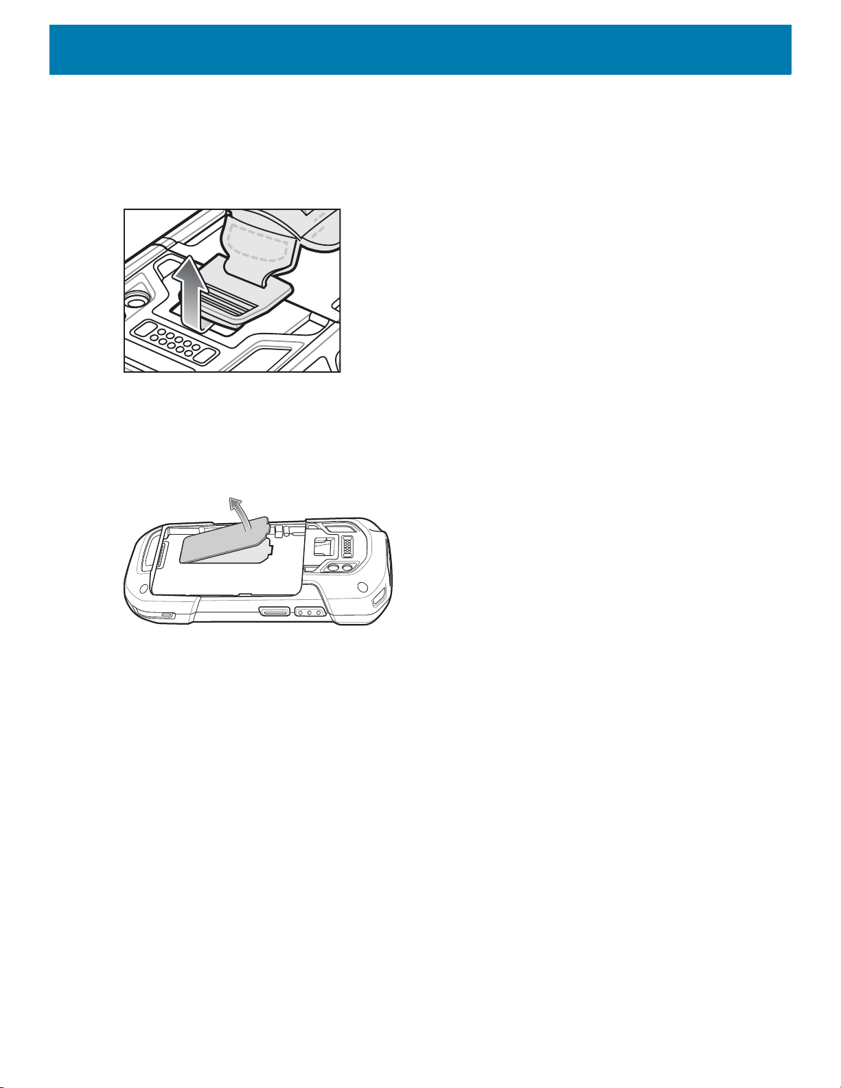
1. Remove the hand strap filler from the hand strap slot. Store the hand strap filler in a safe place for future
replacement.
Figure 17 Remove Filler
2. Insert the hand strap plate into the hand strap slot.
Figure 18 Insert Hand Strap
24

Getting Started
3. Insert the battery, bottom first, into the battery compartment in the back of the device.
Figure 19 Insert Bottom of Battery into Battery Compartment
4. Press the battery down into the battery compartment until the battery release latches snap into place.
Figure 20 Press Down on Battery
5. Place hand strap clip into hand strap mounting slot and pull down until it snaps into place.
Figure 21 Secure Hand Strap Clip
Installing the Battery
NOTE: User modification of the device, particularly in the battery well, such as labels, asset tags, engravings, stickers, etc.,
may compromise the intended performance of the device or accessories. Performance levels such as sealing (Ingress Protection (IP)), impact performance (drop and tumble), functionality, temperature resistance, etc. could be effected. DO NOT
put any labels, asset tags, engravings, stickers, etc. in the battery well.
25

Getting Started
1. Insert the battery, bottom first, into the battery compartment in the back of the device.
Figure 22 Insert Bottom of Battery into Battery Compartment
2. Press the battery down into the battery compartment until the battery release latches snap into place.
Figure 23 Press Down on Battery
Charging the Battery
Before using the device for the first time, charge the main battery until the green Charging/Notification light
emitting diode (LED) remains lit. To charge the device, use a cable or a cradle with the appropriate power
supply. For information about the accessories available for the device, see Accessories for more information.
The 4,620 mAh battery fully charges in less than five hours at room temperature.
Charge batteries in temperatures from 0°C to 40°C (32°F to 104°F). The device or accessory always performs
battery charging in a safe and intelligent manner. At higher temperatures (approximately +37°C (+98°F)) the
device or accessory may, for small periods of time, alternately enable and disable battery charging to keep the
battery at acceptable temperatures. The device or accessory indicates when charging is disabled due to
abnormal temperatures via its LED.
To charge the main battery:
1. Connect the charging accessory to the appropriate power source.
2. Insert the device into a cradle or attach to a cable. The device turns on and begins charging. The
Charging/Notification LED blinks amber while charging, then turns solid green when fully charged.
26

Charging Indicators
Table 1 Charging/Notification LED Charging Indicators
State Indication
Off The device is not charging. The device is not inserted correctly in
Slow Blinking Amber (1 blink every 4
seconds)
Solid Green Charging complete.
Fast Blinking Amber (2 blinks/second) Charging error:
Getting Started
the cradle or connected to a power source. Charger/cradle is not
powered.
The device is charging.
• Temperature is too low or too high.
• Charging has gone on too long without completion (typically
eight hours).
Slow Blinking Red (1 blink every 4
seconds)
Solid Red Charging complete but the battery is at end of useful life.
Fast Blinking Red (2 blinks/second) Charging error but the battery is at end of useful life.
Replacing the Battery
NOTE: User modification of the device, particularly in the battery well, such as labels, asset tags, engravings, stickers, etc.,
may compromise the intended performance of the device or accessories. Performance levels such as sealing (Ingress Protection (IP)), impact performance (drop and tumble), functionality, temperature resistance, etc. could be effected. DO NOT
put any labels, asset tags, engravings, stickers, etc. in the battery well.
CAUTION: Do not add or remove SIM, SAM or microSD card during battery replacement.
1. Remove any accessory attached to the device.
2. Press the Power button until the menu appears.
3. Touch Battery Swap.
The device is charging but the battery is at end of useful life.
• Temperature is too low or too high.
• Charging has gone on too long without completion (typically
eight hours).
4. Follow the on-screen instructions.
5. Wait for the LED to turn off.
27

Getting Started
6. If hand strap is attached, slide the hand strap clip up toward the top of the device and then lift.
Figure 24 Remove Hand Strap Clip
7. Press the two battery latches in.
Figure 25 Press Battery Latches
28

8. Lift the battery from the device.
Figure 26 Lift the Battery
Getting Started
CAUTION: Replace the battery within two minutes. After two minutes the device reboots and data may be lost.
9. Insert the replacement battery, bottom first, into the battery compartment in the back of the device.
10.Press the battery down until the battery release latch snaps into place.
11.Replace the hand strap, if required.
12.Press and hold the Power button to turn on the device.
NOTE: After replacing the battery, wait 15 minutes before using Battery Swap again.
Replacing the SIM or SAM Card
NOTE: SIM replacement applies to TC77 only.
To replace the SIM or SAM card:
1. Press and hold the Power button until the menu appears.
2. Touch Power off.
3. Touch OK.
29

Getting Started
4. If hand strap is attached, slide the hand strap clip up toward the top of the device and then lift.
Figure 27 Remove Hand Strap Clip
5. Press the two battery latches in.
6. Lift the battery from the device.
7. Lift the access door.
Figure 28 Remove Access Door
8. Remove card from holder.
Figure 29 Remove SAM Card
Figure 30 Remove Nano SIM Card
30

9. Insert the replacement card.
Mini SAM Slot
Figure 31 Insert SAM Card
Figure 32 Insert Nano SIM Card
Getting Started
10.Replace the access door.
Figure 33 Replace Access Door
11.Press the access door down and ensure that it is properly seated.
12.Insert the battery, bottom first, into the battery compartment in the back of the device.
13.Press the battery down until the battery release latch snaps into place.
14.Replace the hand strap, if required.
15.Press and hold the Power button to turn on the device.
Replacing the microSD Card
To replace the microSD card:
1. Press the Power button until the menu appears.
31
Getting Started
2. Touch Power off.
3. Touch OK.
4. If hand strap is attached, slide the hand strap clip up toward the top of the device and then lift.
Figure 34 Remove Hand Strap Clip
5. Press the two battery latches in.
6. Lift the battery from the device.
7. Lift the access door.
Figure 35 Remove Access Door
8. Slide the microSD card holder to the Open position.
9. Lift the microSD card holder.
10.Remove microSD card from holder.
11.Insert the replacement microSD card into the card holder door ensuring that the card slides into the holding
tabs on each side of the door.
32

Getting Started
12.Close the microSD card holder door and slide the door to the Lock position.
Figure 36 Close and Lock microSD Card in Holder
13.Replace the access door.
Figure 37 Replace Access Door
14.Press the access door down and ensure that it is properly seated.
CAUTION: Access door must be replaced and securely seated to ensure proper device sealing.
15.Insert the battery, bottom first, into the battery compartment in the back of the device.
16.Press the battery down until the battery release latch snaps into place.
17.Replace the hand strap, if required.
18.Press and hold the Power button to turn on the device.
Resetting the Device
The reset functions include the following:
• Soft reset
• Hard reset
• Enterprise reset
• Factory reset
Performing a Soft Reset
Perform a soft reset if applications stop working.
33

1. Press and hold the Power button until the menu appears.
2. Touch Restart.
The device reboots.
Performing a Hard Reset
CAUTION: Performing a hard reset with a microSD card installed in the device may cause damage or data corruption to the
microSD card. All un-saved data is lost after performing a hard reset.
Perform a hard reset if the device stops responding.
1. Simultaneously press the Power, Scan and Volume Up buttons for at least four seconds.
2. When the screen turns off, release the buttons.
The device reboots.
Getting Started
34

Accessories
Introduction
This chapter provides information for using the accessories for the device.
Accessories
This table lists the accessories available for the device.
Table 2 Accessories
Accessory Part Number Description
Cradles
2-Slot Charge Only
Cradle
2-Slot USB/Ethernet
Cradle
5-Slot Charge Only
Cradle
5-Slot Ethernet Cradle CRD-TC7X-SE5EU1–01 Provides device charging and provides
CRD-TC7X-SE2CPP-01 Provides device and spare battery
CRD-TC7X-SE2EPP-01 Provides device and spare battery
CRD-TC7X-SE5C1-01 Charges up to five devices. Use with power
charging. Use with power supply, p/n
PWR-BGA12V50W0WW.
charging and USB communication with a
host computer and Ethernet
communication with a network. Use with
power supply, p/n
PWR-BGA12V50W0WW.
supply, p/n PWR-BGA12V108W0WW and
DC line cord, p/n CBL-DC-381A1-01. Can
accommodate one 4-Slot Battery Charger
using the Battery Adapter Cup.
Ethernet communication for up to five
devices. Use with power supply, p/n
PWR-BGA12V108W0WW and DC line
cord, p/n CBL-DC-381A1-01. Can
accommodate one 4-Slot Battery Charger
using the Battery Adapter Cup.
Cradle Mount BRKT-SCRD-SMRK-01 Mounts the 5-Slot Charge Only Cradle,
5-Slot Ethernet Cradle, and 4-Slot Battery
Charger to a wall or rack.
35

Table 2 Accessories (Continued)
Accessory Part Number Description
Batteries and Chargers
4,620 mAh
PowerPrecision+ battery
BTRY-TC7X-46MPP-01
BTRY-TC7X-46MPP-10
Accessories
Replacement battery (single pack).
Replacement battery (10–pack).
4-Slot Spare Battery
Charger
Battery Charger Adapter
Cup
Vehicle Solutions
Charging Cable Cup CHG-TC7X-CLA1-01 Provides power to the device from a
Charge Only Vehicle
Cradle
TC7X Data
Communication Enabled
Vehicle Cradle with Hub
Kit
Cigarette Light Adapter
Auto Charge Cable
Hard-wire Auto Charge
Cable
RAM Mount RAM-B-166U Provides window mounting option for the
RAM Mount Base RAM-B-238U RAM 2.43" x 1.31" Diamond Ball base with
SAC-TC7X-4BTYPP-01 Charges up to four battery packs. Use with
power supply, p/n
PWR-BGA12V50W0WW.
CUP-SE-BTYADP1-01 Allows for one 4-Slot Battery Charger to be
charged and docked on the left most slot of
the 5-Slot cradles (maximum one per
cradle).
cigarette lighter socket.
CRD-TC7X-CVCD1-01 Charges and securely holds the device.
Requires power cable
CHG-AUTO-CLA1-01 or
CHG-AUTO-HWIRE1-01, sold separately.
CRD-TC7X-VCD1-01 Contains the TC7X Vehicle
Communication Charging Cradle and the
USB I/O Hub.
CHG-AUTO-CLA1-01 Provides power to the Vehicle Cradle from
a cigarette lighter socket.
CHG-AUTO-HWIRE1-01 Provides power to the Vehicle Cradle from
the vehicle's power panel.
Vehicle Cradle. RAM Twist Lock Suction
Cup with Double Socket Arm and Diamond
Base Adapter. Overall Length: 6.75”.
1" ball.
Charge and Communication Cables
Charging Cable Cup CHG-TC7X-CBL1-01 Provides power to the device. Use with
power supply, p/n PWR-BUA5V16W0WW,
sold separately.
Snap-On USB Cable CBL-TC7X-USB1-01 Provides power to the device and USB
communication with a host computer. Use
with power supply, p/n
PWR-BUA5V16W0WW, sold separately.
MSR Adapter MSR-TC7X-SNP1-01 Provides power and USB communication
with a host computer. Use with USB-C
cable, sold separately.
Snap-On DEX Cable CBL-TC7X-DEX1-01 Provides electronic data exchange with
devices such as vending machines.
36

Accessories
Table 2 Accessories (Continued)
Accessory Part Number Description
Audio Accessories
Rugged Headset HS2100-OTH Rugged wired headset. Includes HS2100
Boom Module and HSX100 OTH
Headband Module.
Bluetooth Headset HS3100-OTH Rugged Bluetooth Headset. Includes
HS3100 Boom Module and HSX100 OTH
Headband Module.
3.5 mm Audio Adapter ADP-TC7X-AUD35-01 Snaps onto the device and provides audio
to a wired headset with 3.5 mm plug.
3.5 mm Headset HDST-35MM-PTVP-01 Use for PTT and VoIP calls.
3.5 mm Quick
Disconnect Adapter
Cable
Scanning
Trigger Handle TRG-TC7X-SNP1-02 Adds gun-style handle with a scanner
Carrying Solutions
ADP-35M-QDCBL1-01 Provides connection to the 3.5 mm
Headset.
trigger for comfortable and productive
scanning.
Soft Holster SG-TC7X-HLSTR1-02 TC7X soft holster.
Rigid Holster SG-TC7X-RHLSTR1-01 TC7X rigid holster.
Hand Strap SG-TC7X-HSTRP2-03 Replacement hand strap with hand strap
mounting clip (3–pack).
Stylus and Coiled Tether SG-TC7X-STYLUS-03 TC7X stylus with coiled tether (3-pack).
Screen Protector SG-TC7X-SCRNTMP-01 Provides additional protection for the
screen (1-pack).
Power Supplies
Power Supply PWR-BUA5V16W0WW Provides power to the device using the
Snap-On USB Cable, Snap-on Serial
Cable or Charging Cable Cup. Requires
DC Line Cord, p/n DC-383A1-01 and
country specific three wire grounded AC
line cord sold separately.
Power Supply PWR-BGA12V50W0WW Provides power to the 2–Slot cradles and
4-Slot Spare Battery Charger. Requires
DC Line Cord, p/n CBL-DC-388A1-01 and
country specific three wire grounded AC
line cord sold separately.
37
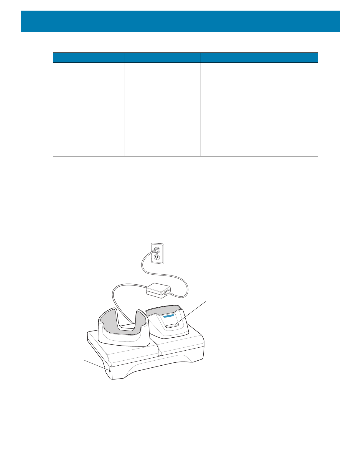
Table 2 Accessories (Continued)
Spare battery Charging LED
Power LED
Accessory Part Number Description
Power Supply PWR-BGA12V108W0WW Provides power to the 5-Slot Charge Only
DC Line Cord CBL-DC-388A1-01 Provides power from the power supply to
DC Line Cord CBL-DC-381A1-01 Provides power from the power supply to
2-Slot Charge Only Cradle
The 2-Slot Charge Only Cradle:
Accessories
cradle and the 5-Slot Ethernet Cradle.
Requires DC Line Cord, p/n
CBL-DC-381A1-01 and country specific
three wire grounded AC line cord sold
separately.
the 2-Slot cradles and 4-Slot Spare Battery
Charger.
the 5-Slot Charge Only Cradle and 5-Slot
Ethernet Cradle.
• Provides 5 VDC power for operating the device.
• Charges the device’s battery.
• Charges a spare battery.
Figure 38 2–Slot Charge Only Cradle
38
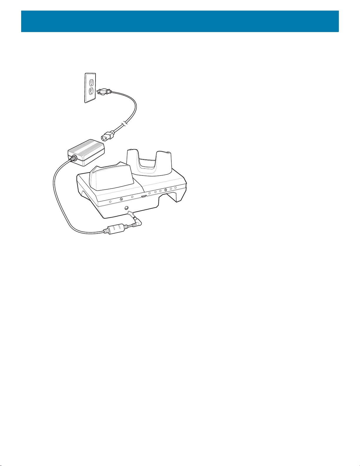
Setup
Accessories
Figure 39 2–Slot Charge Only Cradle
39
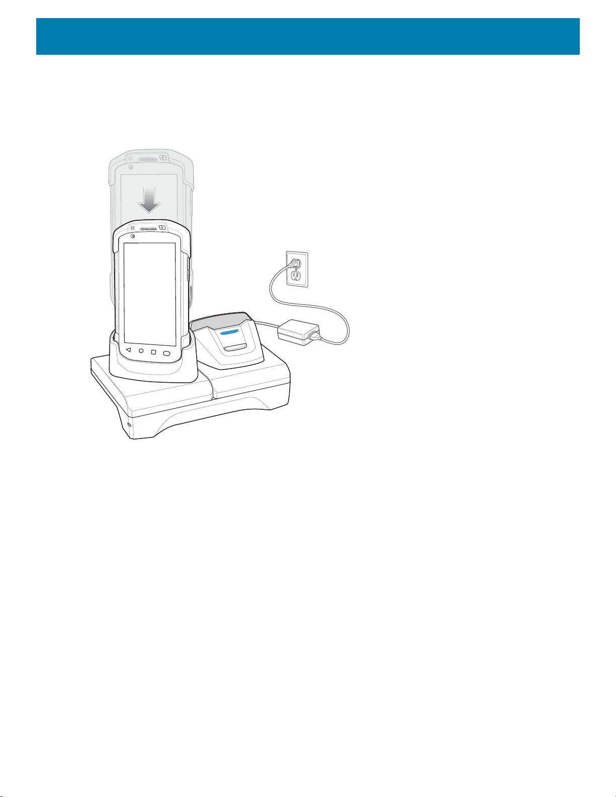
Charging the Device
1. Insert the device into the slot to begin charging.
Figure 40 Battery Charging
Accessories
2. Ensure the device is seated properly.
Charging the Spare Battery
1. Insert the battery into the right slot to begin charging.
40
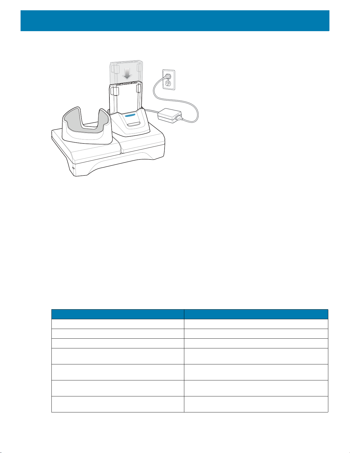
Figure 41 Spare Battery Charging
2. Ensure the battery is seated properly.
Accessories
Battery Charging
Main Battery Charging
The device’s Charging/Notification LED indicates the status of the battery charging in the device.
The 4,620 mAh battery fully charges in less than five hours at room temperature.
Spare Battery Charging
The Spare battery Charging LED on the cup indicates the status of the spare battery charging.
The 4,620 mAh battery fully charges in less than five hours at room temperature.
Table 3 Spare Battery Charging LED Indicators
Slow Blinking Amber Spare battery is charging.
Solid Green Charging complete.
Fast Blinking Amber Error in charging; check placement of spare battery.
Slow Blinking Red Spare battery is charging and battery is at the end of
LED Indication
useful life.
Solid Red Charging complete and battery is at the end of useful
life.
Fast Blinking Red Error in charging; check placement of spare battery and
battery is at the end of useful life.
Off No spare battery in slot; spare battery not placed
correctly; cradle is not powered.
41

Charging Temperature
Spare Battery Charging LED
Power LED
Charge batteries in temperatures from 0 °C to 40 °C (32 °F to 104 °F). The device or cradle always performs
battery charging in a safe and intelligent manner. At higher temperatures (e.g. approximately +37 °C (+98 °F))
the device or cradle may for small periods of time alternately enable and disable battery charging to keep the
battery at acceptable temperatures. The device and cradle indicates when charging is disabled due to
abnormal temperatures via its LED.
2-Slot USB/Ethernet Cradle
The 2-Slot USB/Ethernet Cradle:
• Provides 5.0 VDC power for operating the device.
• Charges the device’s battery.
• Charges a spare battery.
• Connects the device to an Ethernet network.
• Provides communication to a host computer using a USB cable.
NOTE: Remove all attachments on the device, except the hand strap, before place onto the cradle.
Accessories
Figure 42 2-Slot USB/Ethernet Cradle
42

Setup
Accessories
Figure 43 2–Slot USB/Ethernet Cradle
43

Charging the Device
1. Place the bottom of the device into the base.
Figure 44 Battery Charging
Accessories
2. Rotate the top of the device until the connector on the back of the device mates with the connector on the
cradle.
3. Ensure the device is connected properly. The charging Charging/Notification LED on the device begins
blinking amber indicating that the device is charging.
44

Charging the Spare Battery
1. Insert the battery into the right slot to begin charging.
Figure 45 Spare Battery Charging
Accessories
2. Ensure the battery is seated properly.
Battery Charging
Main Battery Charging
The device’s Charging/Notification LED indicates the status of the battery charging in the device.
The 4,620 mAh battery fully charges in less than five hours at room temperature.
Spare Battery Charging
The Spare battery Charging LED on the cup indicates the status of the spare battery charging.
The 4,620 mAh battery fully charges in less than five hours at room temperature.
Table 4 Spare Battery Charging LED Indicators
Slow Blinking Amber Spare battery is charging.
Solid Green Charging complete.
Fast Blinking Amber Error in charging; check placement of spare battery.
Slow Blinking Red Spare battery is charging and battery is at the end of
LED Indication
useful life.
45

Table 4 Spare Battery Charging LED Indicators (Continued)
LED Indication
Solid Red Charging complete and battery is at the end of useful
Fast Blinking Red Error in charging; check placement of spare battery and
Off No spare battery in slot; spare battery not placed
Charging Temperature
Charge batteries in temperatures from 0 °C to 40 °C (32 °F to 104 °F). The device or cradle always performs
battery charging in a safe and intelligent manner. At higher temperatures (e.g. approximately +37 °C (+98 °F))
the device or cradle may for small periods of time alternately enable and disable battery charging to keep the
battery at acceptable temperatures. The device and cradle indicates when charging is disabled due to
abnormal temperatures via its LED.
USB/Ethernet Communication
Accessories
life.
battery is at the end of useful life.
correctly; cradle is not powered.
The 2–Slot USB/Ethernet Cradle provides both Ethernet communication with a network and USB
communication with a host computer. Prior to using the cradle for Ethernet or USB communication. Ensure that
the switch on the USB/Ethernet module is set properly.
Turn the cradle over to view the module.
Figure 46 2–Slot USB/Ethernet Cradle Module Switch
For Ethernet communication, slide the switch to the position.
For USB communication, slide the switch to the position.
Place the switch in the center position to disable communications.
46

Accessories
1
2
Ethernet LED Indicators
There are two LEDs on the USB/Ethernet Module RJ-45 connector. The green LED lights to indicate that the
transfer rate is 100 Mbps. When the LED is not lit the transfer rate is 10 Mbps. The yellow LED blinks to
indicate activity, or stays lit to indicate that a link is established. When it is not lit it indicates that there is no link.
Figure 47 LED Indicators
Table 5 USB/Ethernet Module LED Data Rate Indicators
Data Rate (1) Amber LED (2) Green LED
100 Mbps On/Blink On
10 Mbps On/Blink Off
Ethernet Settings
The following settings can be configured when using Ethernet communication:
• Proxy Settings
• Static IP.
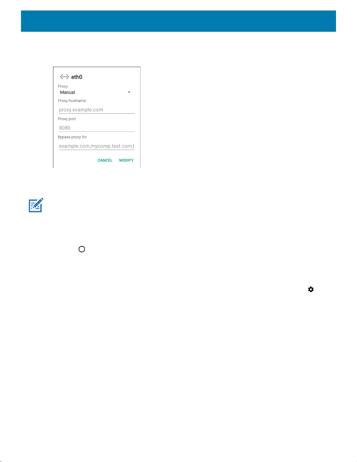
Configuring Ethernet Proxy Settings
The device includes Ethernet cradle drivers. After inserting the device, configure the Ethernet connection:
1. Swipe down with two fingers from the status bar to open the quick access panel and then touch .
2. Touch Network & Internet.
3. Touch Ethernet.
4. Place the device into the Ethernet cradle slot.
5. Slide the switch to the ON position.
6. Touch and hold Eth0 until the menu appears.
7. Touch Modify Proxy.
47
Accessories
8. Touch the Proxy drop-down list and select Manual.
Figure 48 Ethernet Proxy Settings
9. In the Proxy hostname field, enter the proxy server address.
10.In the Proxy port field, enter the proxy server port number.
NOTE: When entering proxy addresses in the Bypass proxy for field, do not use spaces or carriage returns between ad-
dresses.
11.In the Bypass proxy for text box, enter addresses for web sites that do not require to go through the proxy
server. Use the separator “|” between addresses.
12.Touch MODIFY.
13.Touch .
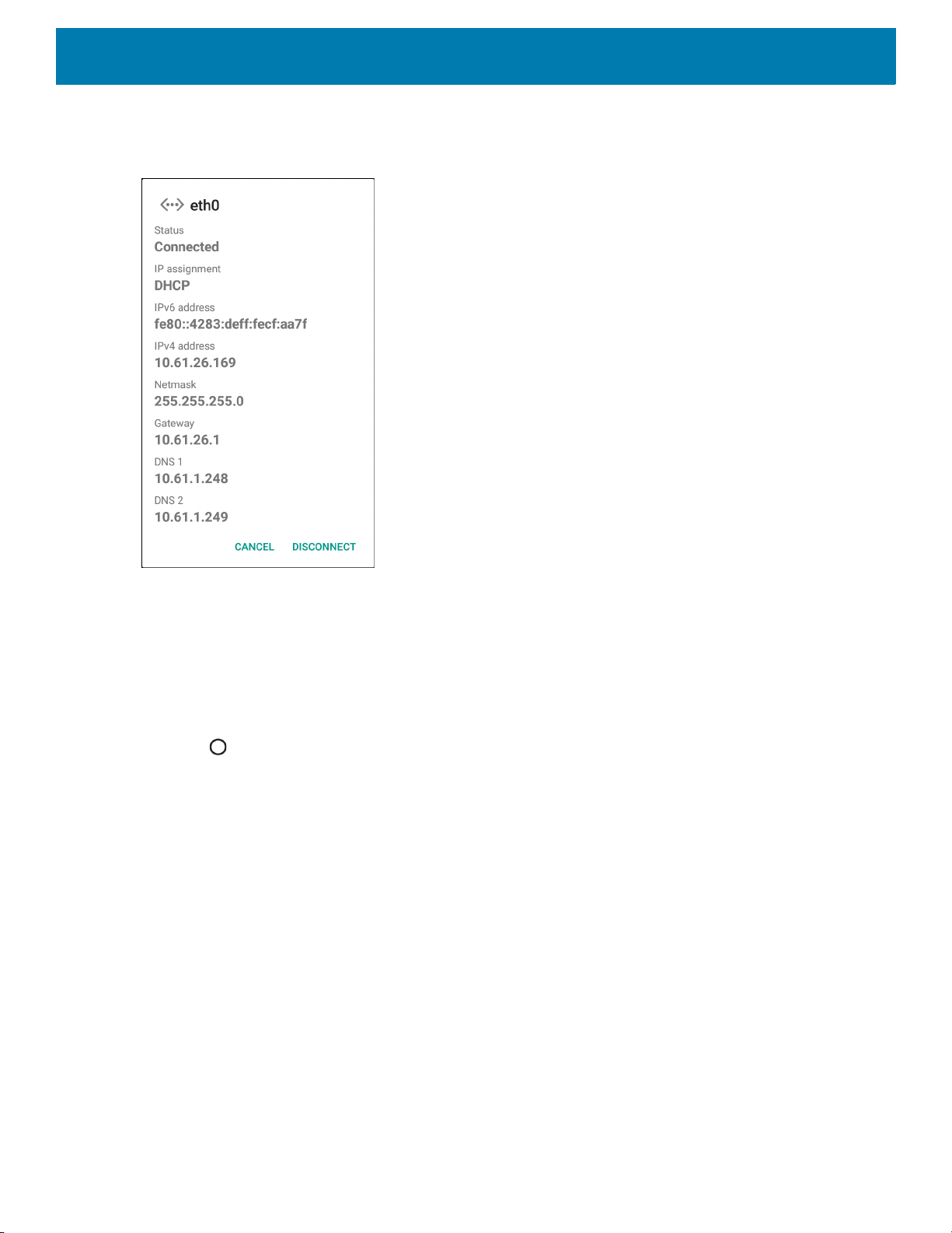
Configuring Ethernet Static IP Address
The device includes Ethernet cradle drivers. After inserting the device, configure the Ethernet connection:
1. Swipe down with two fingers from the status bar to open the quick access panel and then touch .
2. Touch Network & Internet.
3. Touch Ethernet.
4. Place the device into the Ethernet cradle slot.
5. Slide the switch to the ON position.
6. Touch Eth0.
7. Touch Disconnect.
8. Touch Eth0.
48
Accessories
9. Touch and hold the IP settings drop-down list and select Static.
Figure 49 Static IP Settings
10.In the IP address field, enter the proxy server address.
11.If required, in the Gateway field, enter a gateway address for the device.
12.If required, in the Netmask field, enter the network mask address
13.If required, in the DNS address fields, enter a Domain Name System (DNS) addresses.
14.Touch CONNECT.
15.Touch .
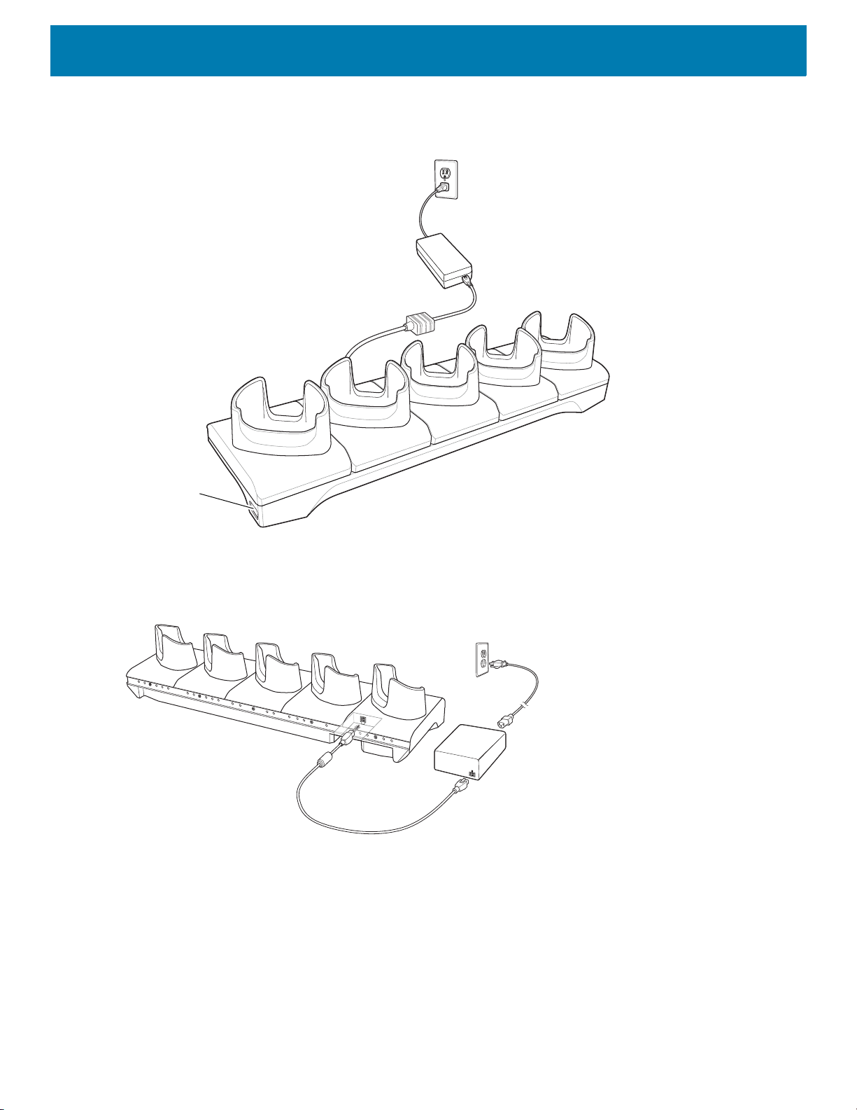
5-Slot Charge Only Cradle
The 5-Slot Charge Only Cradle:
• Provides 5 VDC power for operating the device.
• Simultaneously charges up to five devices and up to four devices and on 4-Slot Battery Charger using the
Battery Charger Adapter. See the TC70x Integrator Guide for information on installing the 4-Slot Battery
Charger onto the cradle.
49
Accessories
Power LED
• Consists of a cradle base and cups that can be configured for various charging requirements.
Figure 50 5-Slot Charge Only Cradle
Setup
Figure 51 5-Slot Charge Only Cradle
50
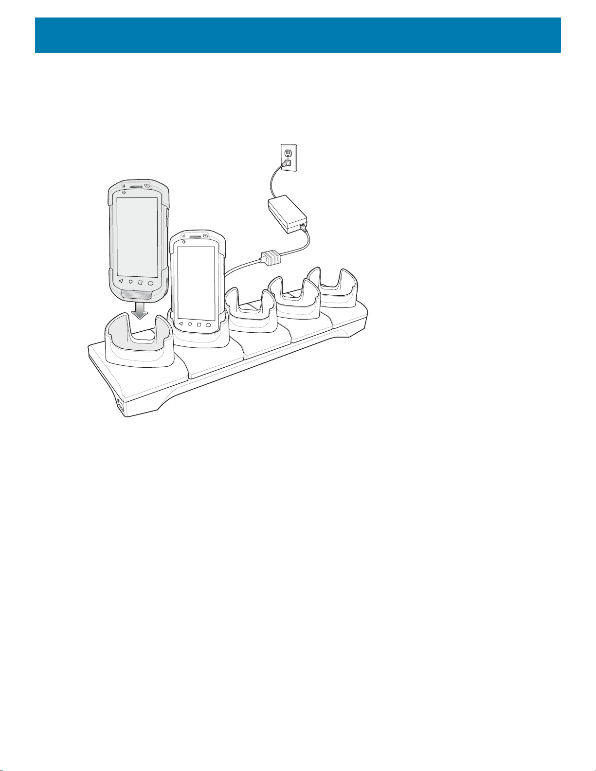
Charging the Device
1. Insert the device into a slot to begin charging.
Figure 52 Battery Charging
Accessories
51
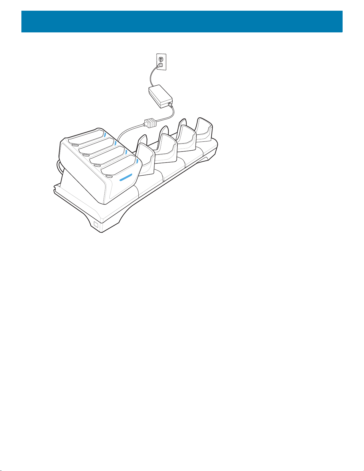
Accessories
Figure 53 5-Slot Charge Only Cradle with Four Slot Battery Charger
2. Ensure the device is seated properly.
Battery Charging
Main Battery Charging
The device’s Charging/Notification LED indicates the status of the battery charging in the device.
The 4,620 mAh battery fully charges in less than five hours at room temperature.
Charging Temperature
Charge batteries in temperatures from 0 °C to 40 °C (32 °F to 104 °F). The device always performs battery
charging in a safe and intelligent manner. At higher temperatures (e.g. approximately +37 °C (+98 °F)) the
device may for small periods of time alternately enable and disable battery charging to keep the battery at
acceptable temperatures. The device indicates when charging is disabled due to abnormal temperatures via its
LED.
52
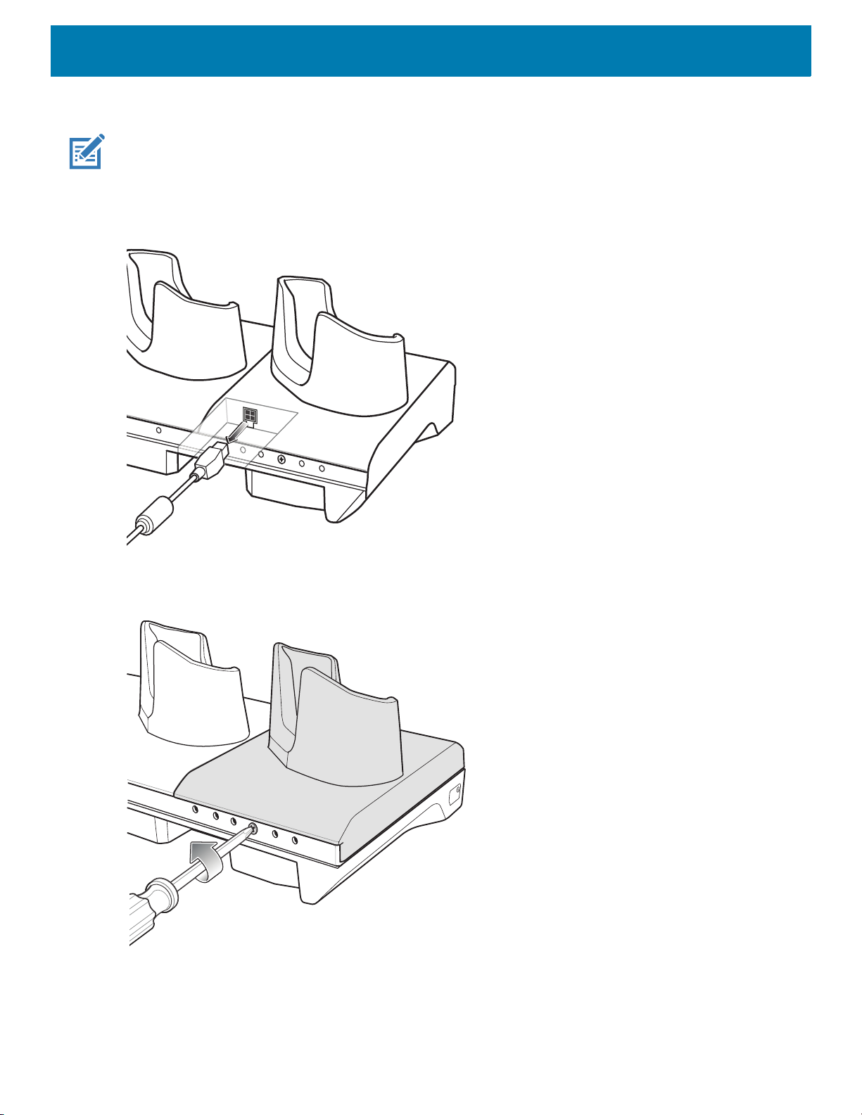
Accessories
Installing the Four Slot Battery Charger
NOTE: The Battery Charger must be installed in the first slot only.
1. Remove power from the cradle.
Figure 54 Remove Power from Cradle
2. Using a Phillips screwdriver, remove the screw securing the cup to the cradle base.
Figure 55 Remove Screw
53
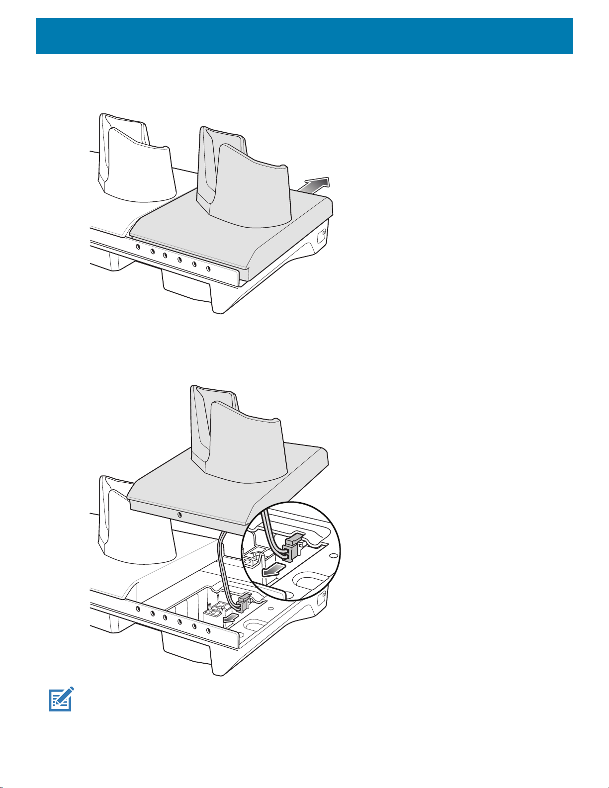
3. Slide the cup to the front of the cradle.
Figure 56 Remove Cup
Accessories
4. Carefully lift the cup up to expose the cup power cable.
5. Disconnect the cup power cable.
Figure 57 Disconnect Cup Power Cable
NOTE: Place power cable into adapter to avoid pinching cable.
54
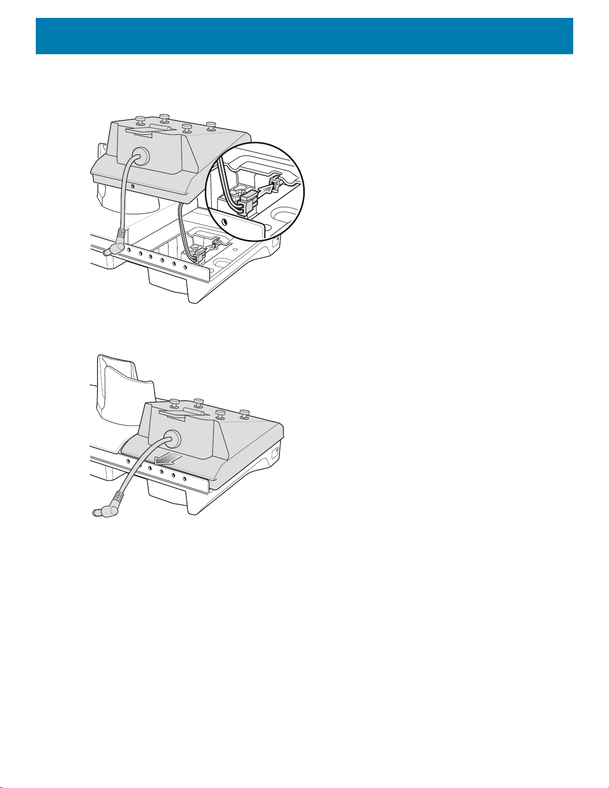
Accessories
6. Connect the Battery Adapter power cable to the connector on the cradle.
Figure 58 Connect Adapter Power Cable
7. Place adapter onto cradle base and slide toward rear of cradle.
Figure 59 Install Adapter
55
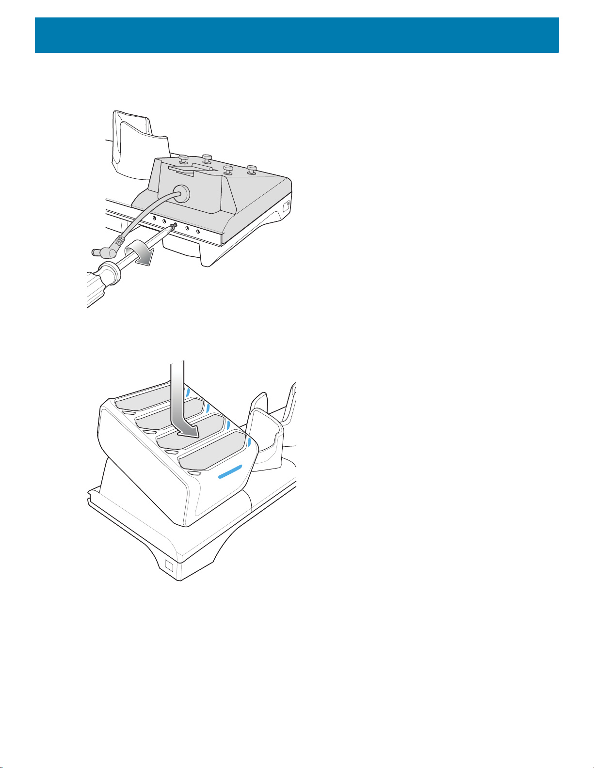
Accessories
8. Using a Phillips screwdriver, secure adapter to cradle base with screw.
Figure 60 Secure adapter to Cradle
9. Align mounting holes on the bottom of the Four Slot Battery Charger with the stubs on the Battery Adapter.
Figure 61 Install Four Slot Battery Charger
10.Slide the Four Slot battery Charger down toward the front of the cradle.
56
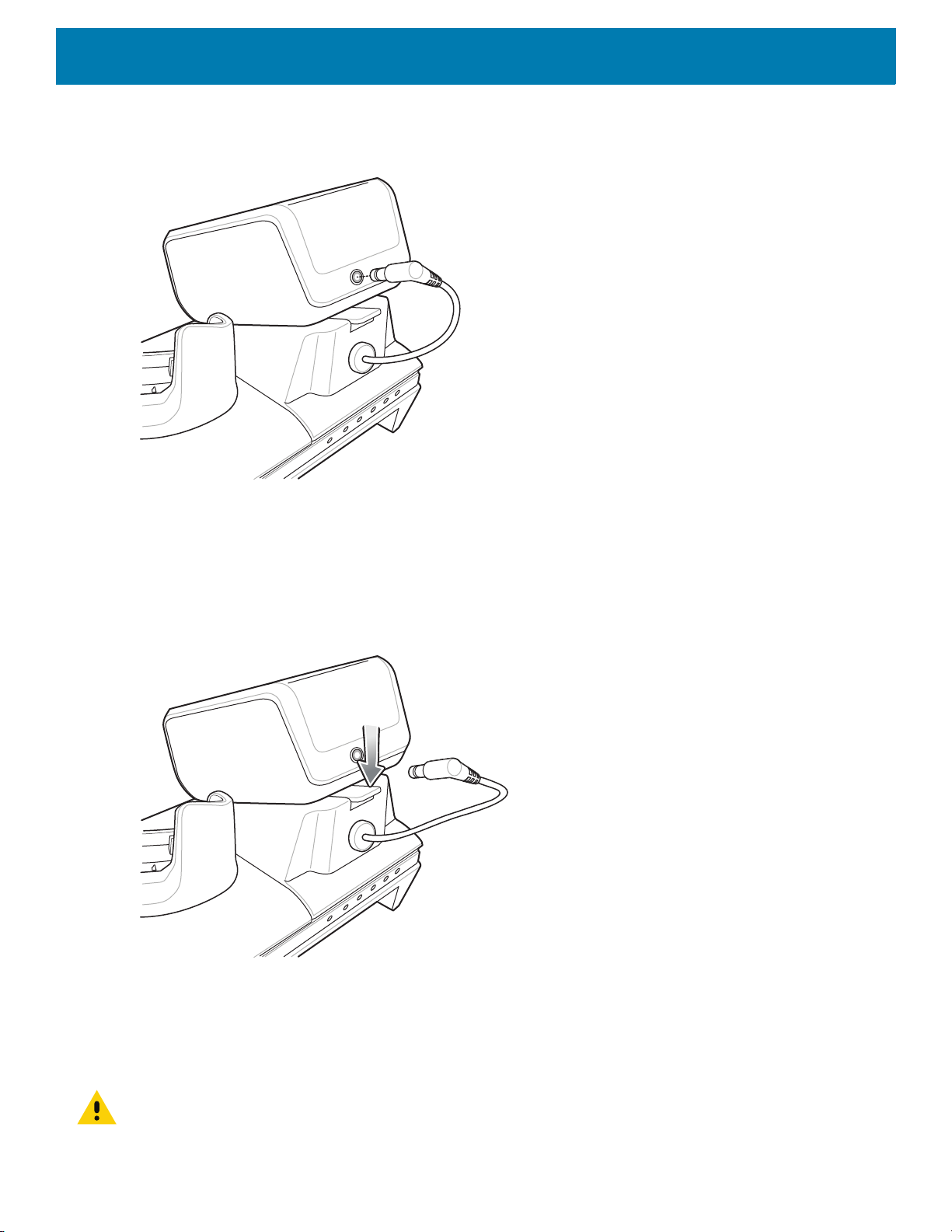
Accessories
11.Connect the output power plug into the power port on the Four Slot Battery Charger.
Figure 62 Connect Output Power Plug
Removing the 4-Slot Battery Charger
1. Disconnect the output power plug from the 4-Slot Battery Charger.
2. At the back of the cup, press down on the release latch.
Figure 63 Press Release Latch
3. Slide the 4-Slot Battery Charger toward the front of the cradle.
4. Lift the 4-Slot off the cradle cup.
5-Slot Ethernet Cradle
CAUTION: Ensure that you follow the guidelines for battery safety described in Battery Safety Guidelines on page 191.
57

Accessories
100/10 LED
1000 LED
The 5-Slot Ethernet Cradle:
• Provides 5.0 VDC power for operating the device.
• Connects the device (up to five) to an Ethernet network.
• Simultaneously charges up to five devices or up to four devices and one 4-Slot Battery Charger using the
Battery Charger Adapter.
Figure 64 5-Slot Ethernet Cradle
58
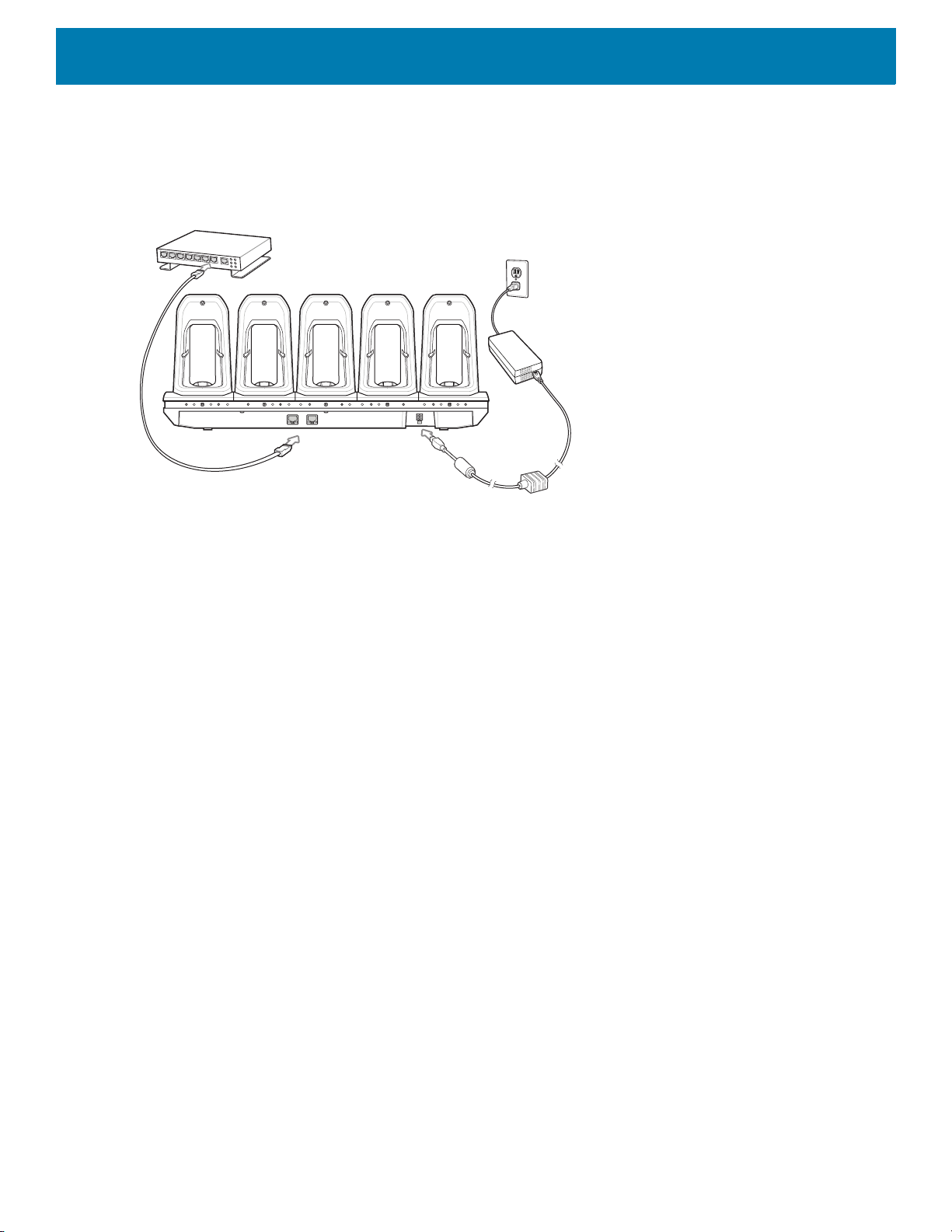
Setup
Accessories
Connect the 5-Slot Ethernet cradle to a power source.
Figure 65 5-Slot Ethernet Cradle Setup
Daisy-chaining Ethernet Cradles
Daisy-chain up to ten 5-Slot Ethernet cradles to connect several cradles to an Ethernet network. Use either a
straight or crossover cable. Daisy-chaining should not be attempted when the main Ethernet connection to the
first cradle is 10 Mbps as throughput issues will almost certainly result.
To daisy-chain 5-Slot Ethernet cradles:
1. Connect power to each 5-Slot Ethernet cradle.
2. Connect an Ethernet cable to the one of the ports on the back of the first cradle and to the Ethernet switch.
59

Accessories
To Switch To Power Supply
To Power SupplyTo Next
Cradle
3. Connect the other end of the Ethernet cable to one of the ports of the back of the second 5-Slot Ethernet
cradle.
Figure 66 Daisy-chaining 5-Slot Ethernet Cradles
4. Connect additional cradles as described in step 2 and 3.
Ethernet Settings
The following settings can be configured when using Ethernet communication:
• Proxy Settings
• Static IP.
Configuring Ethernet Proxy Settings
The device includes Ethernet cradle drivers. After inserting the device, configure the Ethernet connection:
1. Swipe down with two fingers from the status bar to open the quick access panel and then touch .
2. Touch Network & Internet.
3. Touch Ethernet.
4. Place the device into the Ethernet cradle slot.
5. Slide the switch to the ON position.
6. Touch and hold Eth0 until the menu appears.
7. Touch Modify Proxy.
60

Accessories
8. Touch the Proxy drop-down list and select Manual.
Figure 67 Ethernet Proxy Settings
9. In the Proxy hostname field, enter the proxy server address.
10.In the Proxy port field, enter the proxy server port number.
NOTE: When entering proxy addresses in the Bypass proxy for field, do not use spaces or carriage returns between ad-
dresses.
11.In the Bypass proxy for text box, enter addresses for web sites that do not require to go through the proxy
server. Use the separator “|” between addresses.
12.Touch MODIFY.
13.Touch .
Configuring Ethernet Static IP Address
The device includes Ethernet cradle drivers. After inserting the device, configure the Ethernet connection:
1. Swipe down with two fingers from the status bar to open the quick access panel and then touch .
2. Touch Network & Internet.
3. Touch Ethernet.
4. Place the device into the Ethernet cradle slot.
5. Slide the switch to the ON position.
6. Touch Eth0.
7. Touch Disconnect.
8. Touch Eth0.
61

Accessories
9. Touch and hold the IP settings drop-down list and select Static.
Figure 68 Static IP Settings
10.In the IP address field, enter the proxy server address.
11.If required, in the Gateway field, enter a gateway address for the device.
12.If required, in the Netmask field, enter the network mask address
13.If required, in the DNS address fields, enter a Domain Name System (DNS) addresses.
14.Touch CONNECT.
15.Touch .
LED Indicators
There are two green LEDs on the side of the cradle. These green LEDs light and blink to indicate the data
transfer rate.
Table 6 LED Data Rate Indicators
1 Gbps On/Blink Off
100 Mbps Off On/Blink
10 Mbps Off On/Blink
Data Rate 1000 LED 100/10 LED
62

Charging the Device
1. Insert the device into a slot to begin charging.
Figure 69 Battery Charging
Accessories
63
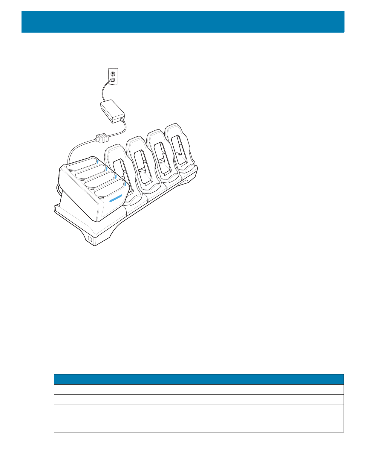
Accessories
2. Ensure the device is seated properly.
Figure 70 5-Slot Ethernet Cradle with 4-Slot Battery Charger
Battery Charging
Main Battery Charging
The device’s Charging/Notification LED indicates the status of the battery charging in the device.
The 4,620 mAh battery fully charges in less than sixfive hours at room temperature.
Spare Battery Charging
The Spare battery Charging LED on the cup indicates the status of the spare battery charging.
The 4,620 mAh battery fully charges in less than five hours at room temperature.
Table 7 Spare Battery Charging LED Indicators
Slow Blinking Amber Spare battery is charging.
Solid Green Charging complete.
Fast Blinking Amber Error in charging; check placement of spare battery.
Slow Blinking Red Spare battery is charging and battery is at the end of
LED Indication
useful life.
64

Table 7 Spare Battery Charging LED Indicators (Continued)
LED Indication
Solid Red Charging complete and battery is at the end of useful
Fast Blinking Red Error in charging; check placement of spare battery
Off No spare battery in slot; spare battery not placed
Charging Temperature
Charge batteries in temperatures from 0 °C to 40 °C (32 °F to 104 °F). The device or cradle always performs
battery charging in a safe and intelligent manner. At higher temperatures (e.g. approximately +37 °C (+98 °F))
the device or cradle may for small periods of time alternately enable and disable battery charging to keep the
battery at acceptable temperatures. The device and cradle indicates when charging is disabled due to
abnormal temperatures via its LED.
Establishing Ethernet Connection
Accessories
life.
and battery is at the end of useful life.
correctly; cradle is not powered.
1. Swipe down with two fingers from the status bar to open the quick access panel and then touch .
2. Touch Network & Internet.
3. Touch Ethernet.
4. Insert the device into a slot.
5. Slide the Ethernet switch to the ON position.
The icon appears in the Status bar.
6. Touch Eth0 to view Ethernet connection details.
Installing the 4-Slot Battery Charger
NOTE: The Battery Charger must be installed in the first slot only.
65
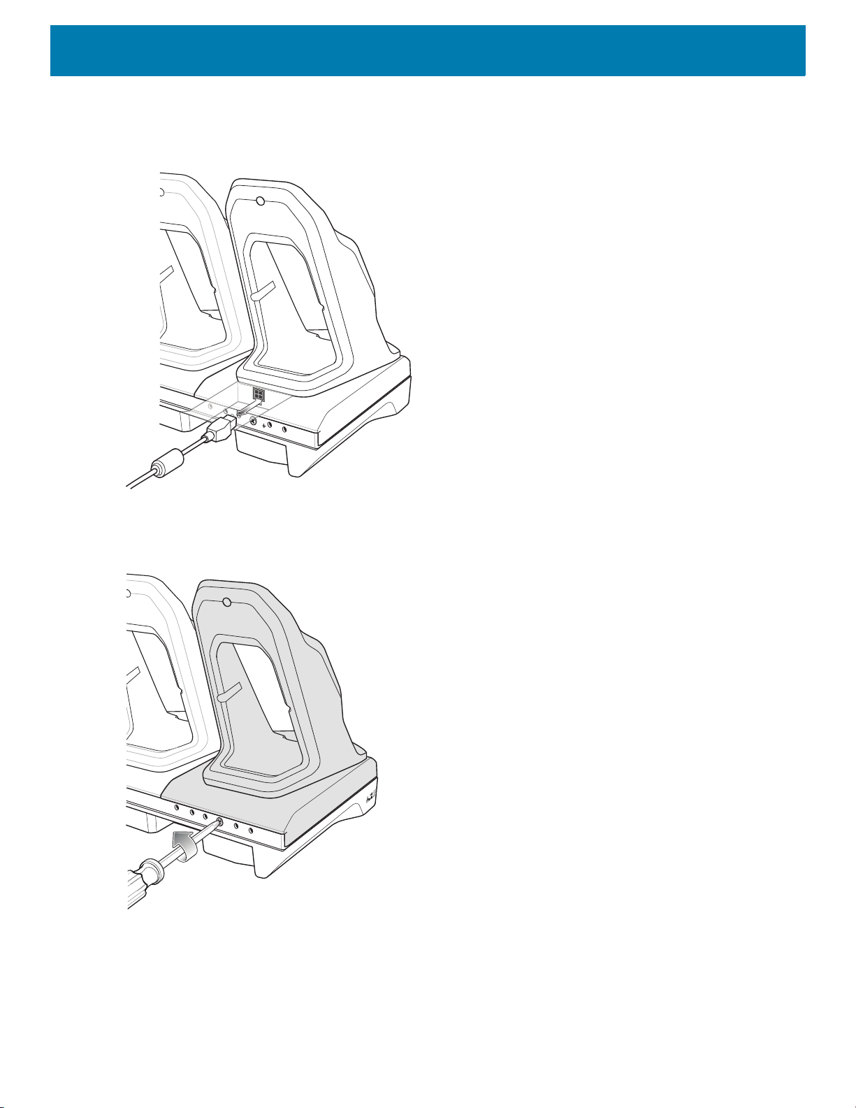
1. Remove power from the cradle.
Figure 71 Remove Power from Cradle
Accessories
2. Using a Phillips screwdriver, remove the screw securing the cup to the cradle base.
Figure 72 Remove Screw
66
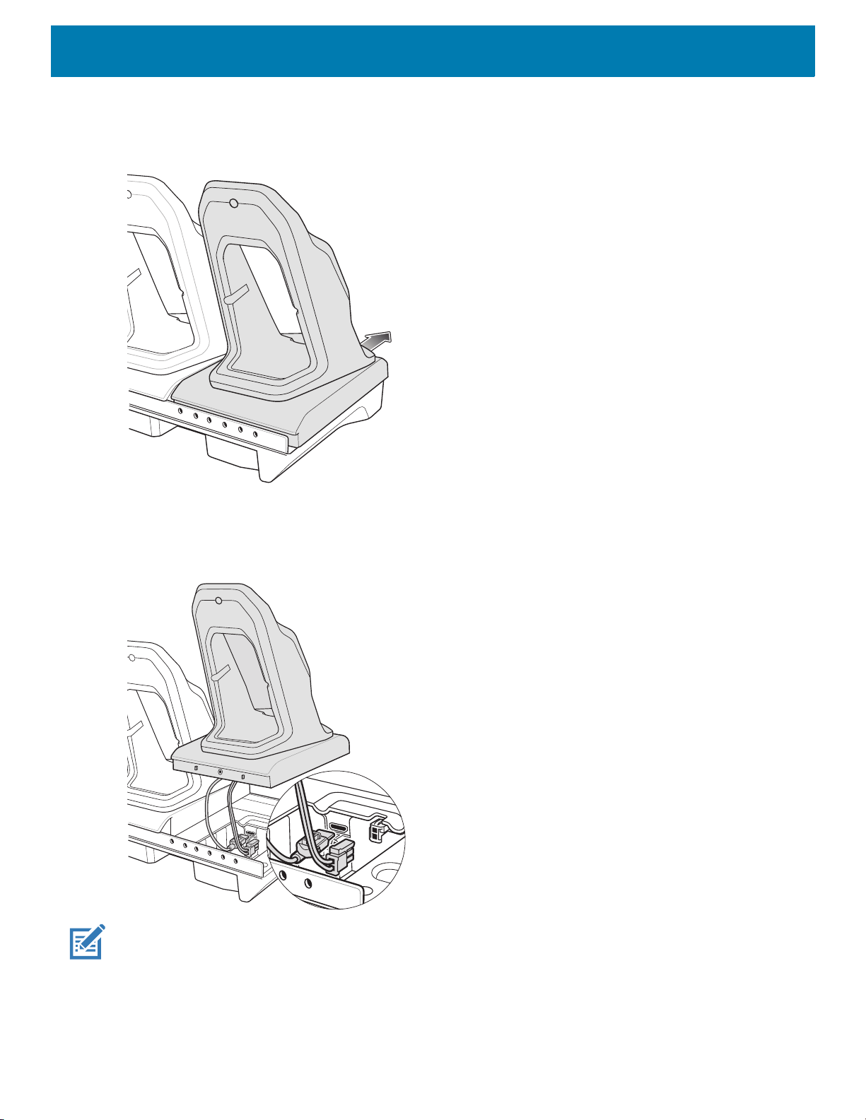
3. Slide the cup to the front of the cradle.
Figure 73 Remove Cup
Accessories
4. Carefully lift the cup up to expose the cup power cable.
5. Disconnect the cup power cable and USB cable.
Figure 74 Disconnect Cup Cables
NOTE: Place power cable into adapter to avoid pinching cable.
67
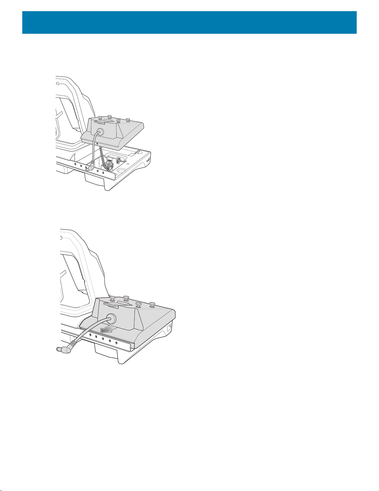
Accessories
6. Connect the Battery Adapter power cable to the connector on the cradle.
Figure 75 Connect Adapter Power Cable
7. Place adapter onto cradle base and slide toward rear of cradle.
Figure 76 Install Adapter
68
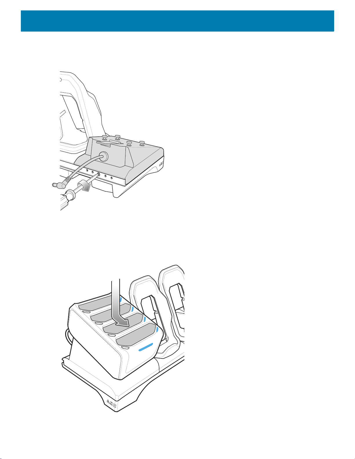
Accessories
8. Using a Phillips screwdriver, secure adapter to cradle base with screw.
Figure 77 Secure adapter to Cradle
9. Align mounting holes on the bottom of the 4-Slot Battery Charger with the stubs on the Battery Adapter.
Figure 78 Install 4-Slot Battery Charger
69
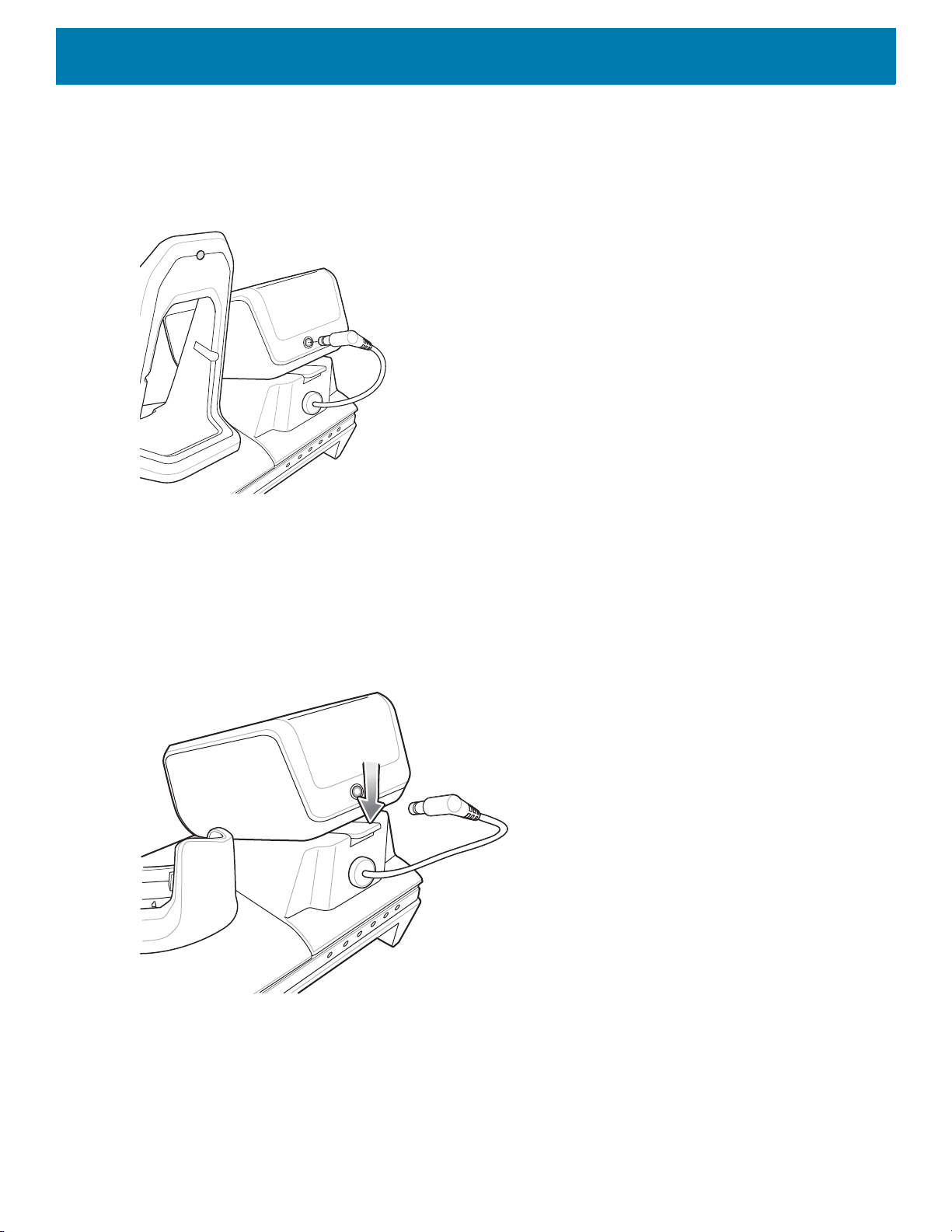
Accessories
10.Slide the 4-Slot battery Charger down toward the front of the cradle.
11.Connect the output power plug into the power port on the 4-Slot Battery Charger.
Figure 79 Connect Adapter Power Cable
Removing the 4-Slot Battery Charger
1. Disconnect the output power plug from the 4-Slot Battery Charger.
2. At the back of the cup, press down on the release latch.
Figure 80 Press Release Latch
3. Slide the 4-Slot Battery Charger toward the front of the cradle.
4. Lift the 4-Slot off the cradle cup.
4-Slot Battery Charger
This section describes how to use the 4-Slot Battery Charger to charge up to four device batteries.
70
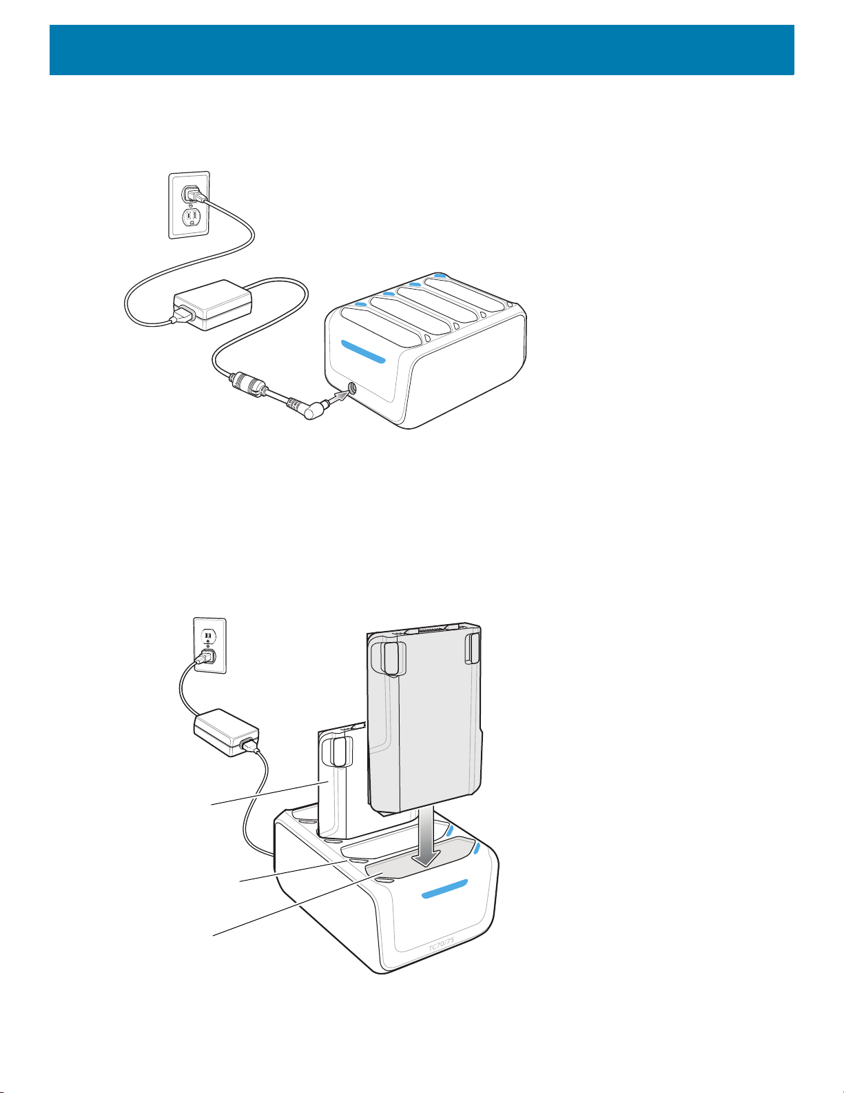
Setup
Battery
Battery Charge LED
Battery Slot
Accessories
Figure 81 Four Slot Battery Charger Power Setup
Charging Spare Batteries
1. Connect the charger to a power source.
2. Insert the battery into a battery charging well and gently press down on the battery to ensure proper
contact.
Figure 82 Four Slot Battery Charger
71

Battery Charging
Spare Battery Charging
Each Battery Charging LED indicates the status of the battery charging in each slot. The table below describes
the Battery Charging LED status.
The 4,620 mAh battery fully charges in less than five hours at room temperature.
Table 8 Battery LED Charging Indicators
LED Indication
Slow Blinking Amber Spare battery is charging.
Solid Green Charging complete.
Fast Blinking Amber Error in charging; check placement of spare battery.
Slow Blinking Red Spare battery is charging and battery is at the end of useful life.
Solid Red Charging complete and battery is at the end of useful life.
Fast Blinking Red Error in charging; check placement of spare battery and battery is at the
Accessories
end of useful life.
Off No spare battery in slot; spare battery not placed correctly; cradle is not
Charging Temperature
Charge batteries in temperatures from 0 °C to 40 °C (32 °F to 104 °F). The battery charger always performs
battery charging in a safe and intelligent manner. At higher temperatures (e.g. approximately +37 °C (+98 °F))
the battery charger may for small periods of time alternately enable and disable battery charging to keep the
battery at acceptable temperatures. The battery charger indicates when charging is disabled due to abnormal
temperatures via its LED.
powered.
72
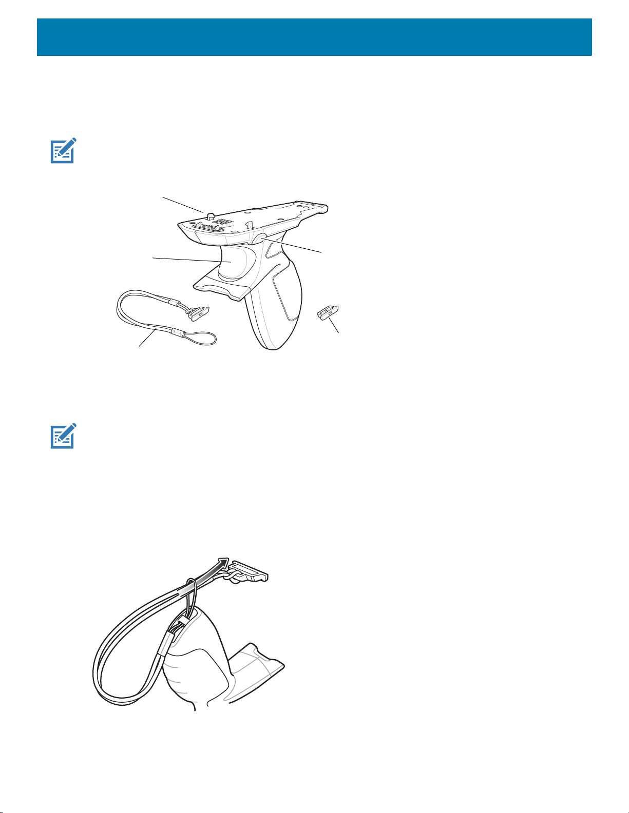
Trigger Handle
Trigger
Attachment Plate with
Tether
Latch
Release Button
Attachment Plate
without Tether
The Trigger Handle adds a gun-style handle with a scanning trigger to the device. It increases comfort when
using the device in scan-intensive applications for extended periods of time.
NOTE: The Attachment Plate with Tether can only be used with Charge Only cradles.
Figure 83 Trigger Handle
Accessories
Installing the Attachment Plate to Trigger Handle
NOTE: Attachment Plate with Tether only.
To install the attachment plate to the Trigger Handle:
1. Insert the loop end of the tether into the slot on the bottom of the handle.
2. Feed the attachment plate through the loop.
Figure 84 Install Attachment Plate to Handle
3. Pull the attachment plate until the loop tightens on the tether.
73

Installing the Trigger Handle Plate
1. Press and hold the Power button until the menu appears.
2. Touch Power off.
3. Touch OK.
4. Press in the two battery latches.
5. Lift the battery from the device.
6. Remove the hand strap filler plate from the hand strap slot. Store the hand strap filler plate in a safe place
for future replacement.
Figure 85 Remove Hand Strap Plate
Accessories
7. Insert the attachment plate into the hand strap slot.
Figure 86 Insert Trigger Handle Plate
8. Insert the battery, bottom first, into the battery compartment in the back of the device.
9. Rotate the top of the battery into the battery compartment.
10.Press the battery down into the battery compartment until the battery release latches snap into place.
74
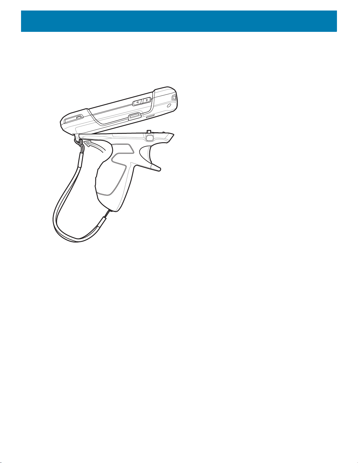
Accessories
Inserting the Device into the Trigger Handle
1. Align the back of the Trigger handle with the Trigger Mounting Plate.
Figure 87 Connect Device to Trigger Handle
2. Press the two release latches.
75

Accessories
3. Rotate the device down and press down until it snaps into place.
Figure 88 Rotate Device onto Trigger Handle
76

Accessories
Removing the Device from the Trigger Handle
1. Press both Trigger Handle release latches.
Figure 89 Press Release Latches
77

Accessories
2. Rotate the device up and remove from the Trigger handle.
Figure 90 Rotate Device onto Trigger Handle
Hand Strap Replacement
CAUTION: Close all running applications prior to replacing the hand strap.
1. Press and hold the Power button until the menu appears.
2. Touch Power Off.
3. Touch OK.
4. Remove the hand strap clip from the hand strap mounting slot.
Figure 91 Remove Hand Strap Clip
78

5. Press the two battery latches in.
Figure 92 Press Battery Latches
Accessories
6. Lift the battery from the device.
Figure 93 Lift the Battery
7. Remove the battery.
79
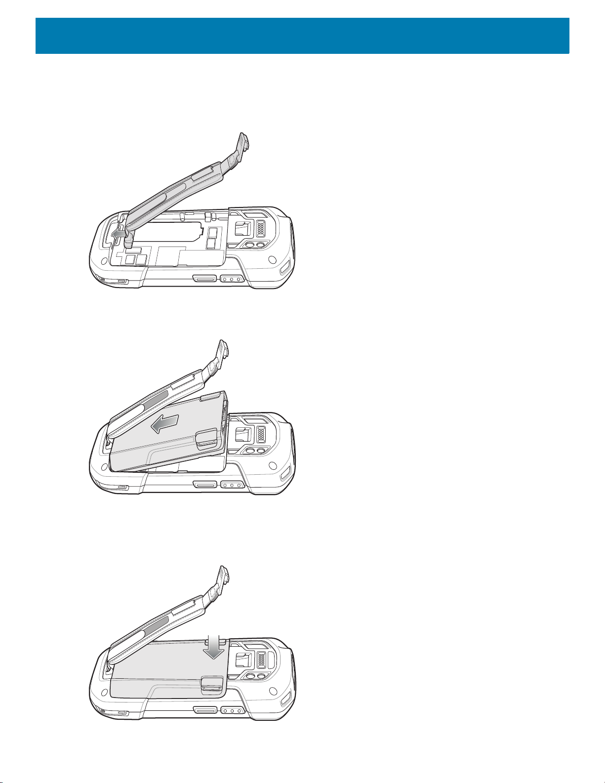
Accessories
8. Remove the hand strap plate from the hand strap slot.
9. Insert the replacement hand strap plate into the hand strap slot.
Figure 94 Insert Hand Strap
10.Insert the battery, bottom first, into the battery compartment.
Figure 95 Insert Bottom of Battery into Battery Compartment
11.Rotate the top of the battery into the battery compartment.
12.Press the battery down into the battery compartment until the battery release latches snap into place.
Figure 96 Press Down on Battery
80
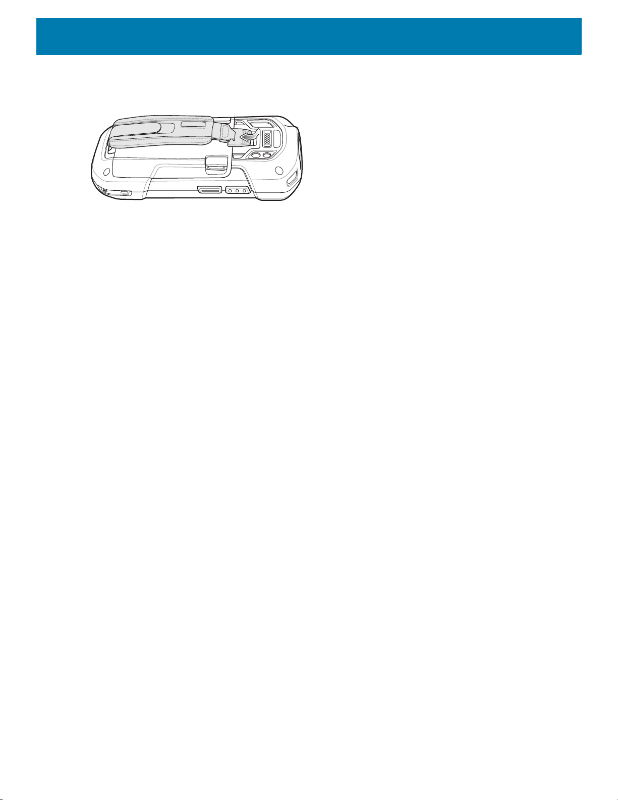
Accessories
13.Place hand strap clip into hand strap mounting slot and pull down until it snaps into place.
Figure 97 Secure Hand Strap Clip
81

Settings
Introduction
This chapter describes settings available for configuring the device.
WWAN Configuration
There are some WWAN configuration options that can be configured by the system administrator.
• Default SIM slot
• Dual SIM Dual Standby
• Network type
• Band preference.
Default SIM Slot Configuration
The device contains two SIM slots that can be used for installing up to two SIM cards. A system
administrator can set the default SIM slot for the device.
By default, SIM slot configuration is disabled. To allow SIM slot configuration on the device, use
Zebra’s staging solution, StageNow, to enable the SIM Socket Selection parameter. See
techdocs.zebra.com/stagenow
To set the default SIM slot on the device:
1. Swipe down from the Status bar to open the Quick Access panel and then touch .
2. Touch Network & Internet > SIM Cards.
3. Select the SIM slot to set as default.
Dual SIM Dual Standby
Dual SIM Dual Standby mode allows a device with two SIM cards to make or receive calls using either
SIM card. Both SIM cards remain active while not in use. When a call is initiated using one SIM card,
the other SIM card becomes inactive until the call ends.
Dual SIM Dual Standby mode is disabled by default. To activate Dual SIM Dual Standby mode, use
Zebra’s staging solution, StageNow. For more information, refer to: www.zebra.com/stagenow
.
.
82

WLAN Configuration
This section provides information on configuring Wi-Fi settings.
Configuring a Secure Wi-Fi Network
To set up a Wi-Fi network:
1. Swipe down from the Status bar to open the Quick Access panel, and then touch .
2. Touch Network & Internet > Wi-Fi.
3. Slide the switch to the ON position.
4. The device searches for WLANs in the area and lists them on the screen.
5. Scroll through the list and select the desired WLAN network.
Settings
83
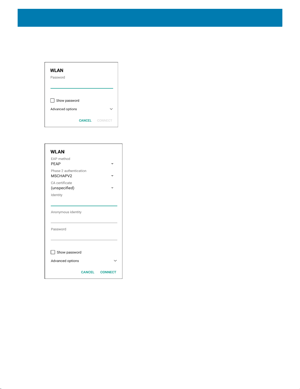
Settings
6. Touch the desired network. If the network security is Open, the device automatically connects to the
network. For all other network security a dialog box appears.
Figure 98 WLAN WEP Network Security Dialog Box
Figure 99 WLAN 802.11 EAP Network Security Dialog Box
7. If the network security is WEP or WPA/WPS2 PSK, enter the required password and then touch Connect.
84

8. If the network security is 802.1x EAP:
• Touch the EAP method drop-down list and select PEAP, TLS, TTLS, or LEAP.
• Touch the Phase 2 authentication drop-down list and select an authentication method.
• If required, touch CA certificate and select a Certification Authority (CA) certificate. Note: Certificates
are installed using the Security settings.
• If required, touch User certificate and select a user certificate. Note: User certificates are installed
using the Location & security settings.
• If required, in the Identity text box, enter the username credentials.
• If desired, in the Anonymous identity text box, enter an anonymous identity username.
• If required, in the Password text box, enter the password for then given identity.
NOTE: By default, the network Proxy is set to None and the IP settings is set to DHCP. See Configuring for a Proxy Server
for setting connection to a proxy server and see Configuring the Device to Use a Static IP Address for setting the device to
use a static IP address.
9. Touch Connect.
10.Touch .
Manually Adding a Wi-Fi Network
Settings
Manually add a Wi-Fi network if the network does not broadcast its name (SSID) or add a Wi-Fi network when
out of range.
1. Swipe down from the Status bar to open the Quick Access panel, and then touch .
2. Touch Network & Internet > Wi-Fi.
3. Slide the Wi-Fi switch to the On position.
4. Scroll to the bottom of the list and select Add network.
5. In the Network name text box, enter the name of the Wi-Fi network.
6. In the Security drop-down list, set the type of security to:
• None
•WEP
• WPA/WPA2 PSK
• 802.1x EAP.
7. If the network security is None, touch Save.
8. If the network security is WEP or WPA/WPA2 PSK, enter the required password, and then touch Save.
85

Settings
9. If the network security is 802.1x EAP:
• Touch the EAP method drop-down list and select PEAP, TLS, TTLS, or LEAP.
• Touch the Phase 2 authentication drop-down list and select an authentication method.
• If required, touch CA certificate and select a Certification Authority (CA) certificate. Note: Certificates
are installed using the Security settings.
• If required, touch User certificate and select a user certificate. Note: User certificates are installed
using the Security settings.
• If required, in the Identity text box, enter the username credentials.
• If desired, in the Anonymous identity text box, enter an anonymous identity username.
• If required, in the Password text box, enter the password for the given identity.
NOTE: By default, the network Proxy is set to None and the IP settings is set to DHCP. See Configuring for a Proxy Server
for setting connection to a proxy server and see Configuring the Device to Use a Static IP Address for setting the device to
use a static IP address.
10.Touch Save. To connect to the saved network, touch and hold on the saved network and select Connect to
network.
11.Touch .
Configuring for a Proxy Server
A proxy server is a server that acts as an intermediary for requests from clients seeking resources from other
servers. A client connects to the proxy server and requests some service, such as a file, connection, web
page, or other resource, available from a different server. The proxy server evaluates the request according to
its filtering rules. For example, it may filter traffic by IP address or protocol. If the request is validated by the
filter, the proxy provides the resource by connecting to the relevant server and requesting the service on behalf
of the client.
It is important for enterprise customers to be able to set up secure computing environments within their
companies, making proxy configuration essential. Proxy configuration acts as a security barrier ensuring that
the proxy server monitors all traffic between the Internet and the intranet. This is normally an integral part of
security enforcement in corporate firewalls within intranets.
To configure the device for a proxy server:
1. Swipe down from the Status bar to open the Quick Access panel, and then touch .
2. Touch Network & Internet > Wi-Fi.
3. Slide the Wi-Fi switch to the On position.
4. In the network dialog box, select and touch a network.
5. Touch Advanced options.
86
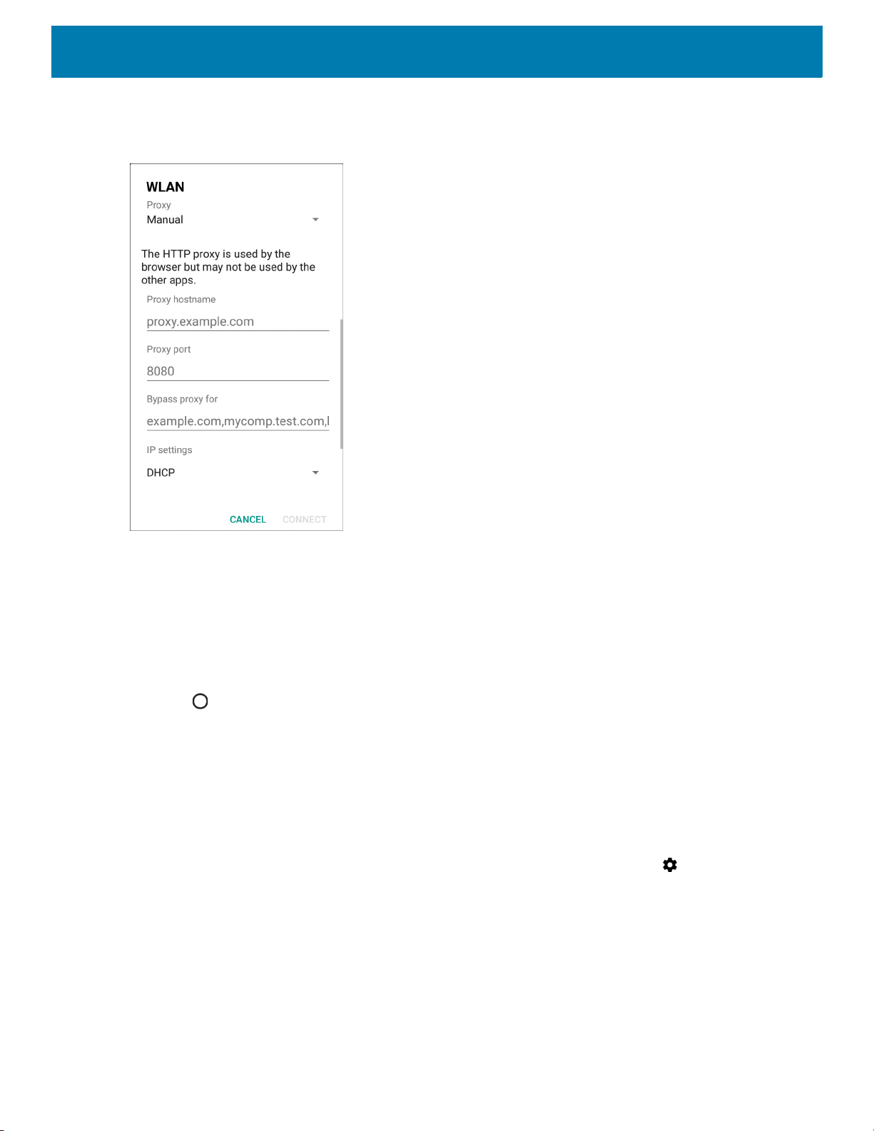
6. Touch Proxy and select Manual.
Figure 100 Proxy Settings
Settings
7. In the Proxy hostname text box, enter the address of the proxy server.
8. In the Proxy port text box, enter the port number for the proxy server.
9. In the Bypass proxy for text box, enter addresses for web sites that are not required to go through the
proxy server. Use a comma “,” between addresses. Do not use spaces or carriage returns between
addresses.
10.Touch Connect.
11.Touch .
Configuring the Device to Use a Static IP Address
By default, the device is configured to use Dynamic Host Configuration Protocol (DHCP) to assign an Internet
protocol (IP) address when connecting to a wireless network.
To configure the device to connect to a network using a static IP address:
1. Swipe down from the Status bar to open the Quick Access panel, and then touch .
2. Touch Network & Internet > Wi-Fi.
3. Slide the Wi-Fi switch to the On position.
4. In the network dialog box, select and touch a network.
5. Touch Advanced options.
87
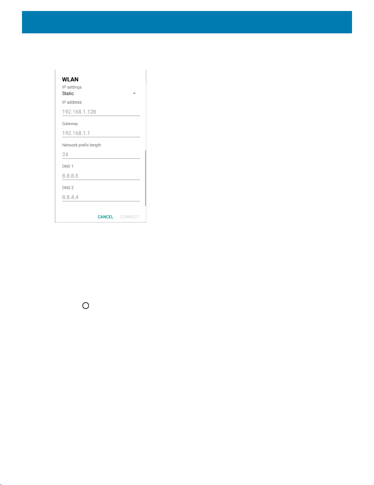
6. Touch IP settings and select Static.
Figure 101 Static IP Settings
Settings
7. In the IP address text box, enter an IP address for the device.
8. If required, in the Gateway text box, enter a gateway address for the device.
9. If required, in the Network prefix length text box, enter the prefix length.
10.If required, in the DNS 1 text box, enter a Domain Name System (DNS) address.
11.If required, in the DNS 2 text box, enter a DNS address.
12.Touch Connect.
13.Touch .
Wi-Fi Preferences
Use the Wi-Fi preferences to configure advanced Wi-Fi settings. From the Wi-Fi screen scroll down to the
bottom of the screen and touch Wi-Fi preferences.
• Open network notification - When enabled, notifies the user when an open network is available.
• Advanced - Touch to expand options.
• Additional settings - See Additional Settings.
• Install Certificates – Touch to install certificates.
• Network rating provider - Disabled (AOSP devices). To help determine what constitutes a good Wi-Fi
network, Android supports external Network rating providers that provide information about the quality of
88

open Wi-Fi networks. Select one of the providers listed or None. If none are available or selected, the
Connect to open networks feature is disabled.
• Wi-Fi Direct - Displays a list of devices available for a direct Wi-Fi connection.
• WPS Push Button - Touch to connect to a network using Wi-Fi Protected Setup (WPS) push button
method.
• WPS Pin Entry - Touch to connect to a network using Wi-Fi Protected Setup (WPS) pin entry method.
• MAC address - Displays the Media Access Control (MAC) address of the device when connecting to
Wi-Fi networks.
• IP address - Displays the IP address of the device when connecting to Wi-Fi networks.
Additional Wi-Fi Settings
NOTE: Additional Wi-Fi settings are for the device, not for a specific wireless network.
Use the Additional Settings to configure additional Wi-Fi settings. To view the additional Wi-Fi settings, scroll
to the bottom of the Wi-Fi screen and touch Wi-Fi Preferences > Advanced > Additional settings.
•Regulatory
• Country Selection - Displays the acquired country code if 802.11d is enabled, else it displays the
currently selected country code.
• Region code - Displays the current region code.
• Band and Channel Selection
• Wi-Fi frequency band - Set the frequency band to: Auto (default), 5 GHz only or 2.4 GHz only.
• Available channels (2.4 GHz) - Touch to display the Available channels menu. Select specific
channels and touch OK.
• Available channels (5 GHz) - Touch to display the Available channels menu. Select specific channels
and touch OK.
• Logging
• Advanced Logging – Touch to enable advanced logging or change the log directory.
• Wireless logs - Use to capture Wi-Fi log files.
• Fusion Logger - Touch to open the Fusion Logger application. This application maintains a history
of high level WLAN events which helps to understand the status of connectivity.
• Fusion Status - Touch to display live status of WLAN state. Also provides information about the
device and connected profile.
• About
• Version - Displays the current Fusion information.
Settings
Wi-Fi Direct
Wi-Fi Direct devices can connect to each other without having to go through an access point. Wi-Fi Direct
devices establish their own ad-hoc network when required, letting you see which devices are available and
choose which one you want to connect to.
1. Swipe down from the status bar and then touch .
89

Settings
2. Touch Wi-Fi > Wi-Fi preferences > Advanced > Wi-Fi Direct. The device begins searching for another
Wi-Fi Direct device.
Figure 102 Wi-Fi Direct Screen
3. Under Peer devices, touch the other device name.
4. On the other device, select Accept.
5. Connected appears on the device. On both devices, in their respective Wi-Fi Direct screens, the other
device name appears in the list.
WPS Push Button
Wi-Fi Protected Setup (WPS) is a feature allowing devices to easily connect to Wi-Fi access points without
typing a long password.
To use a wireless router WPS button:
1. On the device, swipe down from the status bar and then touch .
2. Touch Wi-Fi > Wi-Fi preferences > Advanced > WPS Push Button. A dialog box displays.
Figure 103 WPS Setup Dialog Box
90
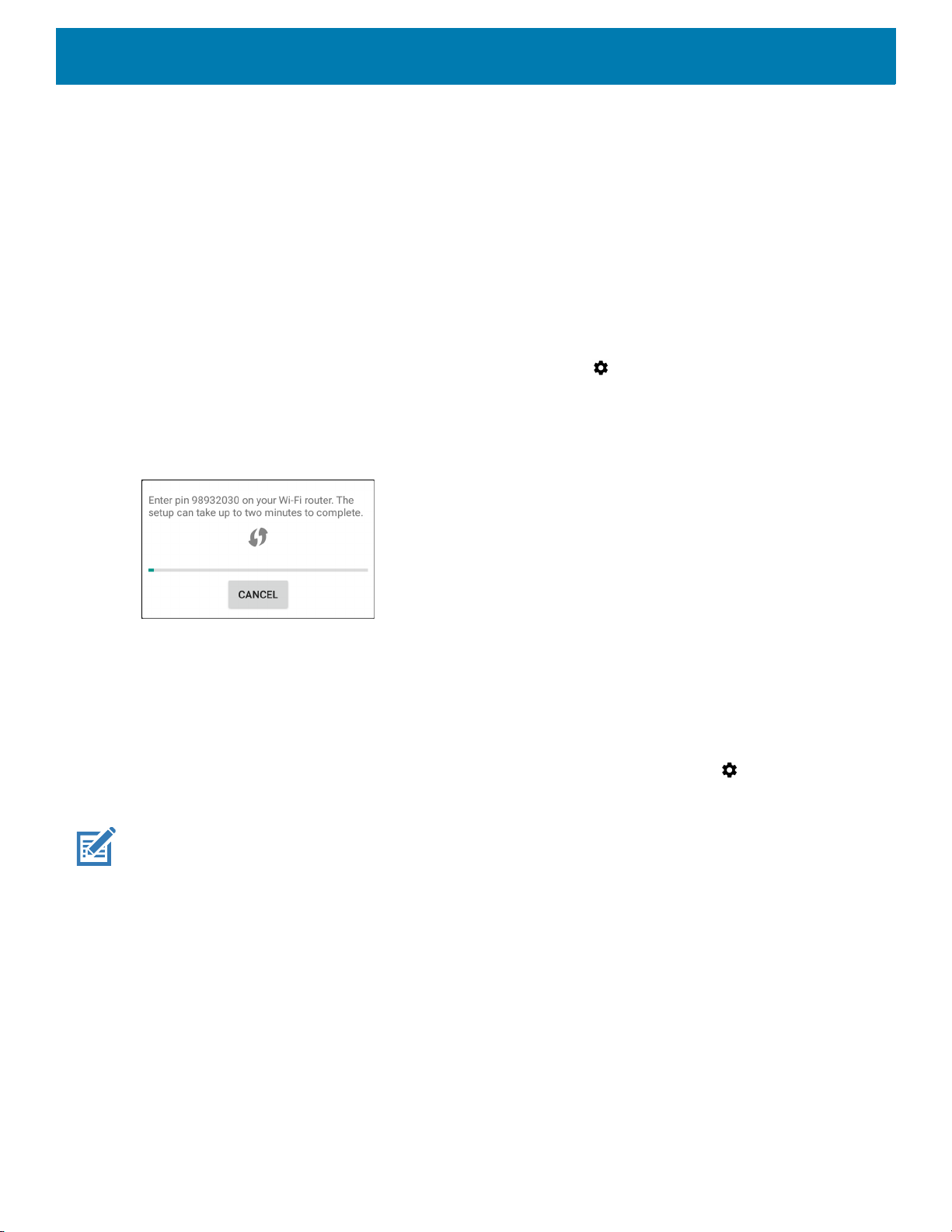
3. On the wireless router, locate the WPS button. The device connects to the wireless router.
WPS Pin Entry
Wi-Fi Protected Setup (WPS) is a feature allowing devices to easily connect to Wi-Fi access points without
typing a long password.
To use a PIN to connect to a wireless router:
1. Log in to the router.
2. Go to the Add WPS Client screen. Refer to the wireless router user documentation specific information.
3. On the device, swipe down from the status bar, and then touch .
4. Touch Wi-Fi > Wi-Fi preferences > Advanced > WPS Pin Entry. A dialog box displays with an Pin
number.
Figure 104 Pin Entry Dialog Box
Settings
5. On the router, enter the Pin number. The device connects to the wireless router.
Setting Screen Lock
Use the Device security settings to set preferences for locking the screen.
1. Swipe down from the Status bar to open the Quick Access panel, and then touch .
2. Touch Security & location.
NOTE: Options vary depending upon the policy of some apps, such as email.
• Screen lock - Touch to configure the device to require a slide, pattern, PIN, or password to unlock the
screen.
• None - Disable screen unlock security.
• Swipe - Slide the lock icon to unlock the screen.
• Pattern - Draw a pattern to unlock screen. See Setting Screen Unlock Using Pattern for more
information.
• PIN - Enter a numeric PIN to unlock screen. See Setting Screen Lock Using PIN for more information.
• Password - Enter a password to unlock screen. See Setting Screen Unlock Using Password for more
information.
Lock the screen to protect access to data on the device. Some email accounts require locking the screen. The
Locking feature functions differently in Single-user versus Multiple-user mode.
91

When locked, a slide, pattern, PIN or password is required to unlock the device. Press the Power button to lock
the screen. The device also locks after a pre-defined time-out.
Press and release the Power button to wake the device. The Lock screen displays.
Slide the screen up to unlock. If the Pattern screen unlock feature is enabled, the Pattern screen appears
instead of the Lock screen.
If the PIN or Password screen unlock feature is enabled, enter the PIN or password after unlocking the screen.
Setting Screen Lock Using PIN
1. Swipe down from the Status bar to open the Quick Access panel, and then touch .
2. Touch Security & location.
3. Touch Screen lock.
4. Touch PIN.
5. To require a PIN upon device start up select Yes, or select No not to require a PIN.
Settings
Figure 105 PIN Screen
6. Touch in the text field.
7. Enter a PIN (4 numbers), and then touch Next.
8. Re-enter PIN and then touch Next.
9. Select the type of notifications that appear when the screen is locked and then touch Done.
10.Touch . The next time the device goes into suspend mode a PIN is required upon waking.
92

Settings
Setting Screen Unlock Using Password
1. Swipe down from the Status bar to open the Quick Access panel, and then touch .
2. Touch Security & location.
3. Touch Screen lock.
4. Touch Password.
5. To require a password upon device start up select Yes, or select No not to require a password.
6. Touch in the text field.
7. Enter a password (between 4 and 16 characters), and then touch Next.
Figure 106 Password Screen
8. Re-enter the password and then touch Next.
9. Select the type of notifications that appear when the screen is locked and then touch Done.
10.Touch . The next time the device goes into suspend mode a password is required upon waking.
Setting Screen Unlock Using Pattern
1. Swipe down from the Status bar to open the Quick Access panel, and then touch .
2. Touch Security & location.
3. Touch Screen lock.
4. Touch Pattern.
93

Settings
5. To require a pattern upon device start up select Yes, or select No not to require a pattern.
Figure 107 Choose Your Pattern Screen
6. Draw a pattern connecting at least four dots.
7. Touch Continue.
8. Re-draw the pattern.
9. Touch Confirm.
10.Select the type of notifications that appear when the screen is locked, and then touch Done.
11.Touch . The next time the device goes into suspend mode a pattern is required upon waking.
Showing Passwords
To set the device to briefly show password characters as the user types:
1. Swipe down from the Status bar to open the Quick Access panel and then touch .
2. Touch Security & location.
3. Slide the Show passwords switch to the ON position.
Remapping a Button
Buttons on the device can be programmed to perform different functions or as shortcuts to installed apps.
NOTE: It is not recommended to remap the scan button.
1. Swipe down from the Status bar to open the Quick Access panel and then touch .
2. Touch Key Programmer. A list of programmable buttons displays.
94

3. Select the button to remap.
4. Touch the BUTTON REMAPPING tab or the SHORTCUT tab that lists the available functions and
5. Touch a function or application shortcut to map to the button.
NOTE: If you select an application shortcut, the application icon appears next to the button on the Key Programmer screen.
6. Touch .
7. If remapping the Back, Home, Search, or Menu button, perform a Soft Reset. See the device User Guide
Accounts
Use the Accounts settings to add, remove, and manage accounts. Use these settings to control how
applications send, receive, and sync data on their own schedules, and whether applications can synchronize
user data automatically.
Settings
applications.
for Android 8.1 Oreo.
Applications may also have their own settings to control how they synchronize data; see the documentation for
those applications for details.
Language Usage
Use the Language & input settings to change the device’s language, including words added to the dictionary.
Changing the Language Setting
1. Swipe down from the Status bar to open the Quick Access panel and then touch .
2. Touch System > Languages & input.
3. Touch Languages. A list of available languages displays.
4. If the desired language is not listed, touch Add a language and select a language from the list.
5. Touch and hold to the right of the desired language, then drag it to the top of the list.
6. The operating system text changes to the selected language.
Adding Words to the Dictionary
1. Swipe down from the Status bar to open the Quick Access panel and then touch .
2. Touch System > Languages & input > Advanced > Personal dictionary.
3. If prompted, select the language where this word or phase is stored.
4. Touch + to add a new word or phrase to the dictionary.
5. Enter the word or phrase.
6. In the Shortcut text box, enter a shortcut for the word or phrase.
95
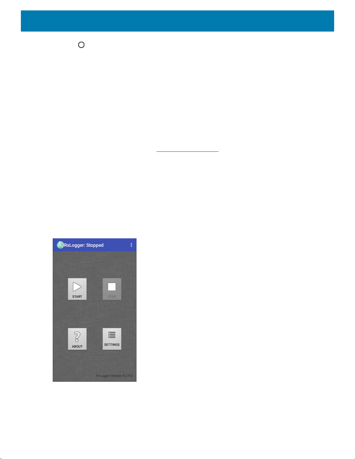
7. Touch .
Keyboard Settings
Use the Languages & input settings to configure the on-screen keyboards. The device contains the following
keyboard settings:
• Android Keyboard - AOSP devices only
• Enterprise Keyboard
• Gboard - GMS devices only.
PTT Express Configuration
Refer to the PTT Express User Guide at www.zebra.com/support for information on configuring the PTT
Express Client application.
RxLogger
RxLogger is a comprehensive diagnostic tool that provides application and system metrics, allows for the
creation of custom plug-ins, and diagnoses device and application issues. RxLogger logs the following
information: CPU load, memory load, memory snapshots, battery consumption, power states, wireless logging,
cellular logging, TCP dumps, Bluetooth logging, GPS logging, logcat, FTP push/pull, ANR dumps, etc. All
generated logs and files are saved onto flash storage on the device (internal or external).
Settings
Figure 108 RxLogger
RxLogger Configuration
RxLogger is built with an extensible plug-in architecture and comes packaged with a number of plug-ins
already built-in. The included plug-ins are described below.
96
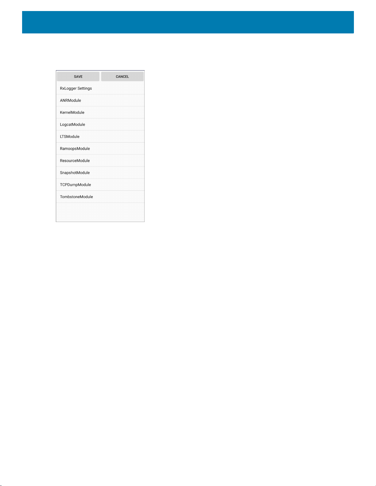
Settings
To open the configuration screen, from the RxLogger home screen touch Settings.
Figure 109 RxLogger Configuration Screen
RxLogger Settings
The RxLogger Settings module provides additional RxLogger settings.
• Enable notifications - Select to allow RxLogger notifications in the Status bar and Notification panel.
• Enable debug logs - Select to enable debug logs.
ANR Module
Application Not Responsive (ANR) indicates that a running application’s UI thread is not responding for a
specified time period. RxLogger is able to detect this condition and trigger a copy of the call stack trace of the
unresponsive application into the log directory. The event is also indicated in the high level CSV log.
• Enable Module - Enables logging for this module.
• Log path - Specifies the default log path to store the ANR log files.
• Collect Historic ANRs - Collects ANR trace files from the system.
Kernel Module
The Kernel Module captures kmsg from the system.
• Enable Module - Enables logging for this kernel module.
• Log path - Specifies the high level log path for storage of all kernel logs. This setting applies globally to all
kernel buffers.
• Kernel Log filename - Specifies the base log filename for this kernel buffer. The current file count is
appended to this name.
• Max Kernel log file size - Specifies the maximum size, in megabytes, of an individual log file.
• Kernel Log interval - Sets the interval, in seconds, on which to flush the log buffer to the file.
97

Settings
• Kernel Log file count - Specifies the number of log files to keep and rotate through. Each log file is subject
to the max log size option.
• Enable System Timestamp in Kernel Log - Enables system timestamps in kernel logs.
• System Timestamp Interval - Sets the interval, in seconds, between system timestamps.
• Enable Logcat Integration override - Enables logcat integration overrides.
Logcat Module
Logcat is an essential debugging tool on Android devices. RxLogger provides the ability to record data from all
four of the available logcat buffers. The Logcat plug-in can collect data from multiple logcat buffers provided by
the system, which are the main, event, radio, and system buffers. Each of the settings are available for each
buffer independently unless otherwise noted.
• Enable Module - Enables logging for this module.
• Log path - Specifies the high level log path for storage of all logcat logs. This setting applies globally to all
logcat buffers.
• Enable main logcat - Enables logging for this logcat buffer.
• Main Log interval (sec) - Sets the interval, in seconds, on which to flush the log buffer to the file.
• Main Log filename - Specifies the base log filename for this logcat buffer. The current file count is
appended to this name.
• Main Log file count - Specifies the number of log files to keep and rotate through. Each log file is
subject to the max log size option.
• Main log file size (MB) - Specifies the maximum size, in megabytes, of an individual log file.
• Main log filter - Custom logcat filter to run on the main buffer.
• Enable event logcat - Enables event logging for this logcat buffer.
• Event log interval (sec) - Sets the interval, in seconds, on which to flush the log buffer to the file.
• Event log filename - Specifies the base log filename for this logcat buffer. The current file count is
appended to this name.
• Event log file count - Specifies the number of log files to keep and rotate through. Each log file is
subject to the max log size option.
• Event log file size (MB) - Specifies the maximum size, in kilobytes, of an individual log file.
• Event log filter - Custom logcat filter to run on the event buffer.
• Enable radio logcat - Enables logging for this logcat buffer.
• Radio log interval (sec) - Sets the interval, in seconds, on which to flush the log buffer to the file.
• Radio log filename - Specifies the base log filename for this logcat buffer. The current file count is
appended to this name.
• Radio log file count - Specifies the number of log files to keep and rotate through
subject to the max log size option.
• Radio log file size (MB) - Specifies the maximum size, in kilobytes, of an individual log file.
• Radio log filter -Custom logcat filter to run on the radio buffer.
. Each log file is
98

Settings
• Enable system logcat - Enables logging for this logcat buffer.
• System log interval (sec) - Sets the interval, in seconds, on which to flush the log buffer to the file.
• System log filename - Specifies the base log filename for this logcat buffer. The current file count is
appended to this name.
• System log file count - Specifies the number of log files to keep and rotate through. Each log file is
subject to the max log size option.
• System log file size (MB) - Specifies the maximum size, in kilobytes, of an individual log file.
• System log filter - Custom logcat filter to run on the system buffer.
• Enable crash logcat- Enables logging for this crash logcat buffer.
• Crash log interval (sec) - Sets the interval, in seconds, on which to flush the log buffer to the file.
• Crash log filename - Specifies the base log filename for this logcat buffer. The current file count is
appended to this name.
• Crash log file count - Specifies the number of log files to keep and rotate through. Each log file is
subject to the max log size option.
• Crash log file size (MB) - Specifies the maximum size, in megabytes, of an individual log file.
• Crash log filter - Custom logcat filter to run on the crash buffer.
• Enable combined logcat - Enables logging for this logcat buffer.
• Enable main buffer - Enable or disable the addition of the main buffer into the combined logcat file.
• Enable event buffer - Enable or disable the addition of the event buffer into the combined logcat file.
• Enable radio buffer - Enable or disable the addition of the radio buffer into the combined logcat file.
• Enable system buffer - Enable or disable the addition of the system buffer into the combined logcat file.
• Enable crash buffer - Enable or disable the addition of the crash buffer into the combined logcat file.
• Combine log interval (sec) - Sets the interval, in seconds, on which to flush the log buffer to the file.
• Combined log filename - Specifies the base log filename for this logcat buffer. The current file count is
appended to this name.
• Combined log file count - Specifies the number of log files to keep and rotate through. Each log file is
subject to the max log size option.
• Combined log file size (MB) - Specifies the maximum size, in megabytes, of an individual log file.
• Combined log filter - Custom logcat filter to run on the combined buffer.
LTS Module
The LTS (Long Term Storage) Module captures data over a long duration of time without losing any data.
Whenever a file is done being written, LTS saves it as a GZ file in an organized path for later use.
• Enable Module - Enables logging for this module.
• Storage Directory - Specifies the high level log path for storage of all logcat logs. This setting applies
globally to all logcat buffers.
Qxdm Module
The Ramoops Module captures Qualcomm Modem Logs from the device.
• Enable Module - Enables logging for this module.
•Log path - Specifies the storage path for Qxdm files.
• Qxdm Log Size - Specifies the maximum size, in kilobytes, of an individual log file.
• Qxdm test sets to keep - Specifies the number of test sets to keep. One test set is a start and stop.
99

Settings
• Choose Log Filter - Select which filter Qxdm uses to process logs.
• Path for User Defined Filter - Specifies the path to a user-defined configuration file.
Ramoops Module
The Ramoops Module captures the last kmsg from the device.
• Enable Module - Enables logging for this module.
• Log path - Specifies the high level log path for storage of all ramoops logs. This setting applies globally to
all Ramoops buffers.
• Base filename - Specifies the base log filename for this kernal buffer. The current file count is appended to
this name.
• Ramoops file count - Specifies the number of log files to keep and rotate through. Each log file is subject
to the log size option.
Resource Module
The Resource Module captures device information and system statistics at specified intervals. The data is
used to determine the health of the device over a period of time.
• Enable Module - Enables logging for this module.
• Log Path - Specifies the high level log path for storage of all resource logs. This setting applies globally to
all resource buffers.
• Resource Log interval - Sets the interval, in seconds, on which to flush the log buffer to the file.
• Resource Log file size - Specifies the maximum size, in megabytes, of an individual log file.
• Resource Log file count - Specifies the number of log files to keep and rotate through. Each log file is
subject to the max log size option.
• Power - Enables or disables the collection of Battery statistics.
• System Resource- Enables or disables the collection of System Resource information.
• Network - Enables or disables the collection of Network status.
• Bluetooth - Enables or disables the collection of Bluetooth information.
• Light - Enables or disables the collection of ambient light level.
• Heater - Not supported.
Snapshot Module
The Snapshot Module collects detailed device statistics at an interval to see detailed device information.
• Enable Module - Enables logging for this module.
• Log Path - Specifies the base path to use to store the snapshot files
• Log filename - Specifies the base filename for all the snapshot files. The current file count is appended to
this name.
• Log Interval (sec) - Specifies the interval, in seconds, on which to invoke a detailed snapshot.
• Snapshot file count - The maximum number of Snapshot files to keep at any one time.
• Top - Enables or disables the running of the
• CPU Info - Enables detailed per process CPU logging in the snapshot.
• Memory Info - Enables logging of detailed per process memory usage in the snapshot.
• Battery Info - Enables logging of detailed power information including battery life, on time, charging, and
wake locks.
top command for data collection.
100
 Loading...