


TC72 / TC77
Touch Computer
Quick Start Guide
MN-003372-05EN

Copyright
ZEBRA and the stylized Zebra head are trademarks of Zebra Technologies Corporation, registered in many
jurisdictions worldwide. All other trademarks are the property of their respective owners.
©2019-2020 Zebra Technologies Corporation and/or its affiliates. All rights reserved.
COPYRIGHTS & TRADEMARKS: For complete copyright and trademark information, go to
www.zebra.com/copyright
TC72/TC77 Quick Start Guide
.
WARRANTY: For complete warranty information, go to www.zebra.com/warranty
END USER LICENSE AGREEMENT: For complete EULA information, go to www.zebra.com/eula
Terms of Use
• Proprietary Statement
This manual contains proprietary information of Zebra Technologies Corporation and its subsidiaries
(“Zebra Technologies”). It is intended solely for the information and use of parties operating and maintaining
the equipment described herein. Such proprietary information may not be used, reproduced, or disclosed to
any other parties for any other purpose without the express, written permission of Zebra Technologies.
• Product Improvements
Continuous improvement of products is a policy of Zebra Technologies. All specifications and designs are
subject to change without notice.
• Liability Disclaimer
Zebra Technologies takes steps to ensure that its published Engineering specifications and manuals are
correct; however, errors do occur. Zebra Technologies reserves the right to correct any such errors and
disclaims liability resulting therefrom.
• Limitation of Liability
In no event shall Zebra Technologies or anyone else involved in the creation, production, or delivery of the
accompanying product (including hardware and software) be liable for any damages whatsoever (including,
without limitation, consequential damages including loss of business profits, business interruption, or loss of
business information) arising out of the use of, the results of use of, or inability to use such product, even if
Zebra Technologies has been advised of the possibility of such damages. Some jurisdictions do not allow
the exclusion or limitation of incidental or consequential damages, so the above limitation or exclusion may
not apply to you.
.
.
2

Features
Menu Button
Touch Screen
Scan Button
PTT Button
Back Button
Home Button
Microphone
Charging Contacts
Speaker
Front Facing
Camera (optional)
Data Capture LED
Search Button
Light Sensor
Proximity Sensor
Power Button
Microphone
Receiver
Charging/Notification LED
Interface
Connector
Camera
Elastic Sleeve
Battery Release Latches
Volume Up/Down Button
Battery
Microphone
Camera Flash
Exit Window
Hand Strap Mounting Point
Battery Release Latches
Hand Strap
Scan Button
TC72/TC77 Quick Start Guide
3

TC72/TC77 Quick Start Guide
Removing the SIM Lock Access Cover
NOTE: TC77 with SIM Lock only.
TC77 models with the SIM Lock feature include an access door that is secured using a Microstix 3ULR-0
screw. To remove the access cover, use a Microstix TD-54(3ULR-0) screwdriver to remove the screw from the
access panel.
Figure 1 Remove Secure Access Cover Screw
After re-installing the access cover, make sure to use a Microstix TD-54(3ULR-0) screwdriver to re-install the
screw.
Installing the SIM Card
NOTE: A SIM card is only required on the TC77.
NOTE: Only use a nano SIM card.
CAUTION: For proper electrostatic discharge (ESD) precautions to avoid damaging the SIM card. Proper ESD precautions
include, but not limited to, working on an ESD mat and ensuring that the user is properly grounded.
4

TC72/TC77 Quick Start Guide
nano SIM
Slot 1 (default)
nano SIM
Slot 2
1. Lift the access door.
Figure 2 Remove Access Door
Figure 3 TC77 SIM Slot Locations
2. Slide the SIM card holder to the unlock position.
Figure 4 Unlock SIM Card Holder
5

TC72/TC77 Quick Start Guide
3. Lift the SIM card holder door.
Figure 5 Lift the SIM Card Holder
4. Place the nano SIM card into the card holder with contacts facing down.
Figure 6 Place SIM Card in Holder
5. Close the SIM card holder door and slide to the lock position.
Figure 7 Close and Lock SIM Card Holder Door
6

6. Replace the access door.
Mini SAM Slot
Figure 8 Replace Access Door
7. Press the access door down and ensure that it is properly seated.
CAUTION: Access door must be replaced and securely seated to ensure proper device sealing.
Installing the SAM Card
CAUTION: Follow proper electrostatic discharge (ESD) precautions to avoid damaging the Secure Access Module (SAM)
card. Proper ESD precautions include, but not limited to, working on an ESD mat and ensuring that the user is properly
grounded.
TC72/TC77 Quick Start Guide
NOTE: If using a micro SAM card, a third-party adapter is required.
1. Lift the access door.
Figure 9 Remove Access Door
2. Insert a SAM card into the SAM slot with the cut edge toward the middle of the device and the contacts
facing down.
Figure 10 SAM Card Installation
3. Ensure that the SAM card is seated properly.
7

4. Replace the access door.
Figure 11 Replace Access Door
5. Press the access door down and ensure that it is properly seated.
CAUTION: Access door must be replaced and securely seated to ensure proper device sealing.
Installing a microSD Card
The microSD card slot provides secondary non-volatile storage. The slot is located under the battery pack.
Refer to the documentation provided with the card for more information, and follow the manufacturer’s
recommendations for use.
TC72/TC77 Quick Start Guide
CAUTION: Follow proper electrostatic discharge (ESD) precautions to avoid damaging the microSD card. Proper ESD pre-
cautions include, but are not limited to, working on an ESD mat and ensuring that the operator is properly grounded.
1. Remove the hand strap, if installed.
2. Lift the access door.
Figure 12 Remove Access Door
3. Slide the microSD card holder to the Open position.
Figure 13 Open microSD Card Holder
8

TC72/TC77 Quick Start Guide
4. Lift the microSD card holder.
Figure 14 Lift microSD Card Holder
5. Insert the microSD card into the card holder door ensuring that the card slides into the holding tabs on each
side of the door.
Figure 15 Insert microSD Card into Holder
6. Close the microSD card holder door and slide the door to the Lock position.
Figure 16 Close and Lock microSD Card in Holder
9

TC72/TC77 Quick Start Guide
7. Replace the access door.
Figure 17 Replace Access Door
8. Press the access door down and ensure that it is properly seated.
CAUTION: Access door must be replaced and securely seated to ensure proper device sealing.
Installing the Hand Strap and Battery
NOTE: User modification of the device, particularly in the battery well, such as labels, asset tags, engravings, stickers, etc.,
may compromise the intended performance of the device or accessories. Performance levels such as sealing (Ingress Protection (IP)), impact performance (drop and tumble), functionality, temperature resistance, etc. could be effected. DO NOT
put any labels, asset tags, engravings, stickers, etc. in the battery well.
NOTE: Installation of the hand strap is optional. Skip this section if not installing the hand strap.
1. Remove the hand strap filler from the hand strap slot. Store the hand strap filler in a safe place for future
replacement.
Figure 18 Remove Filler
2. Insert the hand strap plate into the hand strap slot.
Figure 19 Insert Hand Strap
10

TC72/TC77 Quick Start Guide
3. Insert the battery, bottom first, into the battery compartment in the back of the device.
Figure 20 Insert Bottom of Battery into Battery Compartment
4. Press the battery down into the battery compartment until the battery release latches snap into place.
Figure 21 Press Down on Battery
5. Place hand strap clip into hand strap mounting slot and pull down until it snaps into place.
Figure 22 Secure Hand Strap Clip
11

Installing the Battery
NOTE: User modification of the device, particularly in the battery well, such as labels, asset tags, engravings, stickers, etc.,
may compromise the intended performance of the device or accessories. Performance levels such as sealing (Ingress Protection (IP)), impact performance (drop and tumble), functionality, temperature resistance, etc. could be effected. DO NOT
put any labels, asset tags, engravings, stickers, etc. in the battery well.
1. Insert the battery, bottom first, into the battery compartment in the back of the device.
Figure 23 Insert Bottom of Battery into Battery Compartment
2. Press the battery down into the battery compartment until the battery release latches snap into place.
Figure 24 Press Down on Battery
TC72/TC77 Quick Start Guide
12
Charging the Device
Use one of the following accessories to charge the device and/or spare battery.
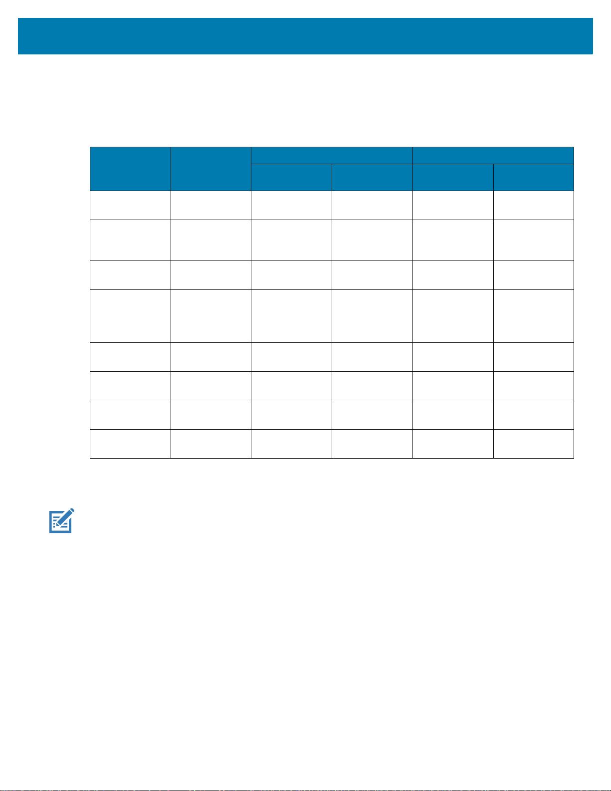
Table 1 Charging and Communication
Description Part Number
2-Slot Charge
Only Cradle
2-Slot
USB/Ethernet
Cradle
5-Slot Charge
Only Cradle
4-Slot Charge
Only Cradle
with Battery
Charger
5-Slot Ethernet
Cradle
CRD-TC7X-SE
2CPP-01
CRD-TC7X-SE
2EPP-01
CRD-TC7X-SE
5C1-01
CRD-TC7X-SE
5KPP-01
CRD-TC7X-SE
5EU1–01
TC72/TC77 Quick Start Guide
Charging Communication
Battery
(In Device)
Yes Yes No No
Yes Yes Yes Yes
YesNoNoNo
Yes Yes No No
Yes No No Yes
Spare Battery USB Ethernet
4-Slot Spare
Battery Charger
Snap-On USB
Cable
Charging Cable
Cup
SAC-TC7X-4B
TYPP-01
CBL-TC7X-CB
L1-01
CHG-TC7X-CL
A1-01
Charging the TC72/TC77
NOTE: Ensure that you follow the guidelines for battery safety described in the device User Guide.
1. Insert the device into the charging slot or connect the USB Charge cable to the device.
2. Ensure the device is seated properly.
The Notification/Charge LED lights amber while charging, then turns solid green when fully charged. See
Table 2 for charging indicators.
The 4,620 mAh battery fully charges in less than five hours at room temperature.
No Yes No No
Yes No Yes No
YesNoNoNo
13
TC72/TC77 Quick Start Guide
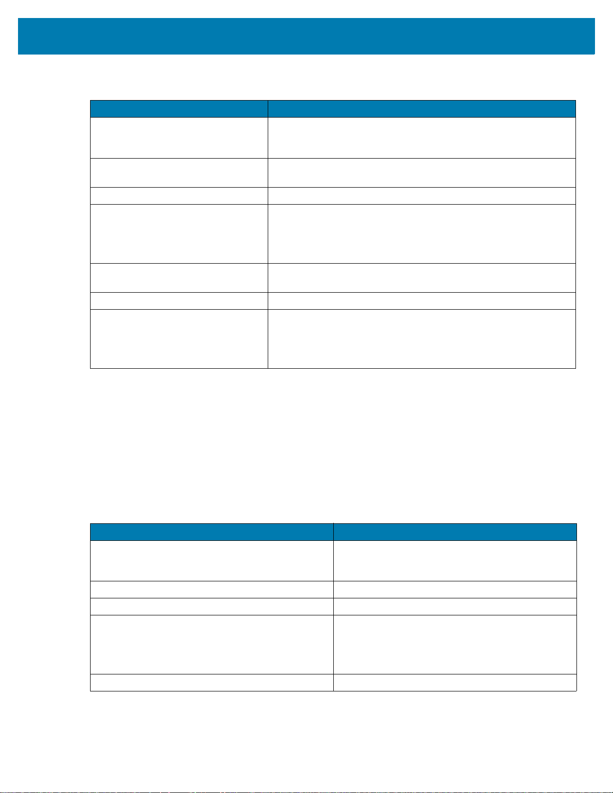
Table 2 Charging/Notification LED Charging Indicators
State Indication
Off The device is not charging. The device is not inserted correctly in
the cradle or connected to a power source. Charger/cradle is not
powered.
Slow Blinking Amber (1 blink every 4
seconds)
Solid Green Charging complete.
Fast Blinking Amber (2 blinks/second) Charging error, e.g.:
Slow Blinking Red (1 blink every 4
seconds)
Solid Red Charging complete but the battery is at end of useful life.
Fast Blinking Red (2 blinks/second) Charging error but the battery is at end of useful life., e.g.:
The device is charging.
Temperature is too low or too high.
Charging has gone on too long without completion (typically eight
hours).
The device is charging but the battery is at end of useful life.
Temperature is too low or too high.
Charging has gone on too long without completion (typically eight
hours).
Charging the Spare Battery
1. Insert a spare battery into the spare battery slot.
2. Ensure the battery is seated properly.
The Spare Battery Charging LED blinks indicating charging. See Table 3 for charging indicators.
The 4,620 mAh battery fully charges in less than five hours at room temperature.
Table 3 Spare Battery Charging LED Indicators
State Indication
Off The battery is not charging. The battery is not
Solid Amber Battery is charging.
Solid Green Battery charging is complete.
Fast Blinking Red
(2 blinks/second)
Solid Red Unhealthy battery is charging or fully charged.
inserted correctly in the cradle or connected to a
power source. Cradle is not powered.
Charging error, e.g.:
- Temperature is too low or too high.
- Charging has gone on too long without completion
(typically eight hours).
Charge batteries in temperatures from 0°C to 40°C (32°F to 104°F). The device or cradle always performs
battery charging in a safe and intelligent manner. At higher temperatures (e.g. approximately +37°C (+98°F))
the device or cradle may for small periods of time alternately enable and disable battery charging to keep the
14

TC72/TC77 Quick Start Guide
Spare Battery
Charging LED
Power LED
Power LED
Spare Battery
Charging LED
battery at acceptable temperatures. The device and cradle indicates when charging is disabled due to
abnormal temperatures via its LED.
2-Slot Charging Only Cradle
2-Slot USB/Ethernet Cradle
15

5-Slot Charge Only Cradle
Power LED
TC72/TC77 Quick Start Guide
16

5-Slot Ethernet Cradle
1000 LED
100/10 LED
TC72/TC77 Quick Start Guide
17

4-Slot Battery Charger
Battery
Battery
Charge LED
Battery Slot
TC72/TC77 Quick Start Guide
Snap-On USB Cable
18
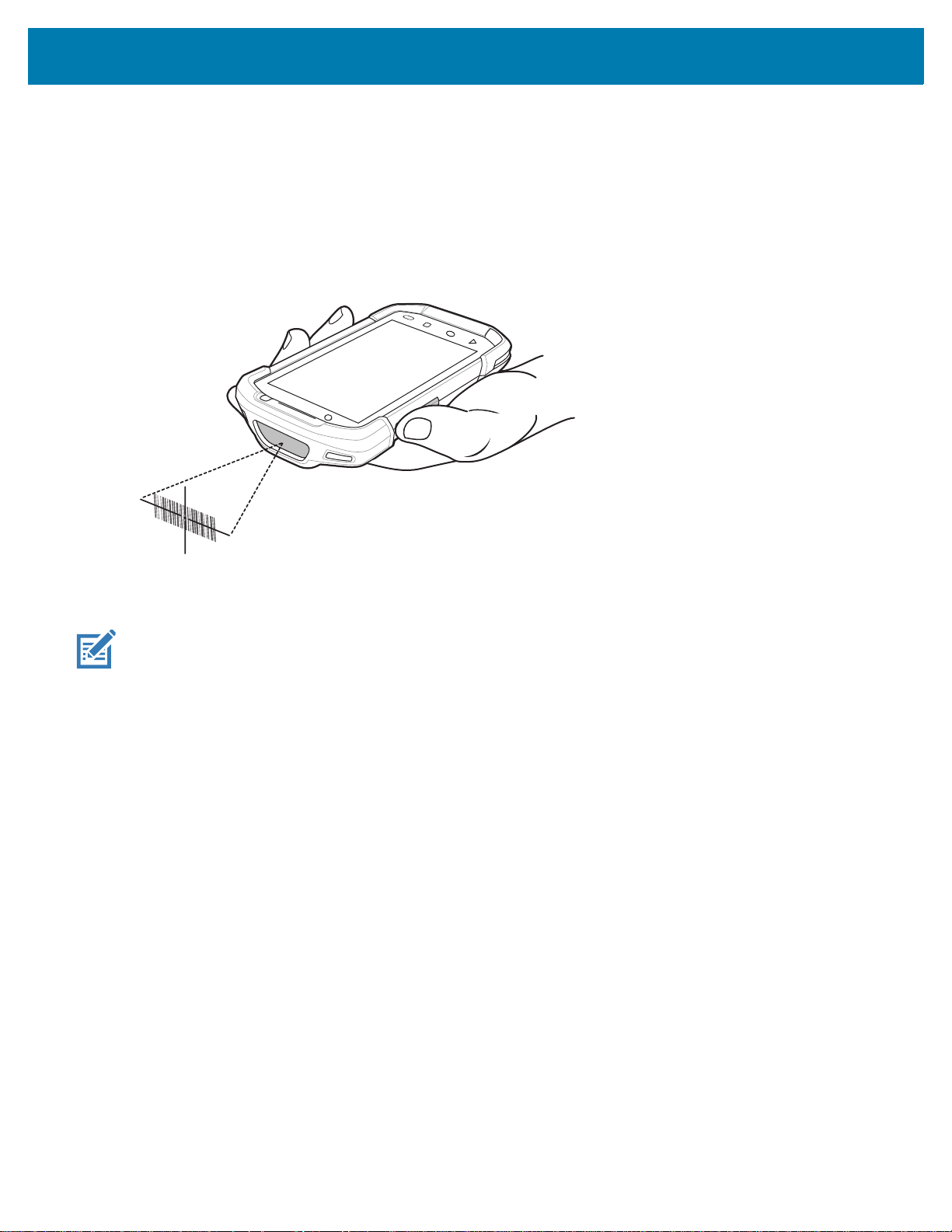
Imager Scanning
To read a bar code, a scan-enabled application is required. The device contains the DataWedge application
that allows the user to enable the imager, decode the bar code data and display the bar code content.
1. Ensure that an application is open on the device and a text field is in focus (text cursor in text field).
2. Point the exit window on the top of the device at a bar code.
Figure 25 Imager Scanning
TC72/TC77 Quick Start Guide
3. Press and hold the scan button.
The red laser aiming pattern turns on to assist in aiming.
NOTE: When the device is in Picklist mode, the imager does not decode the bar code until the crosshair or aiming dot touch-
es the bar code.
19

TC72/TC77 Quick Start Guide
4. Ensure the bar code is within the area formed by the crosshairs in the aiming pattern. The aiming dot is
used for increased visibility in bright lighting conditions.
Figure 26 Aiming Pattern
Figure 27 Pick List Mode with Multiple Barcodes
5. The Data Capture LED lights green and a beep sounds, by default, to indicate the bar code was decoded
successfully.
6. Release the scan button.
The bar code content data displays in the text field.
NOTE: Imager decoding usually occurs instantaneously. The device repeats the steps required to take a digital picture (im-
age) of a poor or difficult bar code as long as the scan button remains pressed.
20

www.zebra.com
 Loading...