

Page 1
TC70x/TC75x
MN-002882-03
Touch Computer
Integrator Guide
for Android™ Version 6.0.1
Page 2

Page 3

TC70X/TC75X INTEGRATOR GUIDE
FOR ANDROID VERSION 6.0.1
MN-002882-03
Rev A
May 2018
Page 4

ii TC70x/TC75x Integrator Guide
No part of this publication may be reproduced or used in any form, or by any electrical or mechanical means, without
permission in writing from Zebra. This includes electronic or mechanical means, such as photocopying, recording, or
information storage and retrieval systems. The material in this manual is subject to change without notice.
The software is provided strictly on an “as is” basis. All software, including firmware, furnished to the user is on a
licensed basis. Zebra grants to the user a non-transfer able and non-exclu sive license to use each software or firmware
program delivered hereunder (licensed program). Except as noted below, such license may not be assigned,
sublicensed, or otherwise transferred by the user without prior written consent of Zebra. No right to copy a licensed
program in whole or in part is granted, except as permitted under copyright law. The user shall not modify, merge, or
incorporate any form or portion of a licensed program with other program material, create a derivative work from a
licensed program, or use a licensed program in a network without written permission from Zebra. The user agrees to
maintain Zebra’s copyright notice on the licensed programs delivered hereunder, and to include the same on any
authorized copies it makes, in whole or in part. The user agrees not to decompile, disassemble, decode, or reverse
engineer any licensed program delivered to the user or any portion thereof.
Zebra reserves the right to make changes to any software or product to improve reliability, function, or design.
Zebra does not assume any product liability arising out of, or in connection with, the application or use of any product,
circuit, or application described herein.
No license is granted, either expressly or by implication, estoppel, or otherwise under any Zebra Technologies
Corporation, intellectual property rights. An implied license only exists for equipment, circuits, and subsystems
contained in Zebra products.
Page 5

Revision History
Changes to the original manual are listed below:
Change Date Description
Rev A 1/2017 Initial release.
-02 Rev. A 2/2017 Add TC70x support.
-03 Rev. A 5/2018 Update approved cleanser active ingredients.
iii
Page 6

iv TC70x/TC75x Integrator Guide
Page 7

TABLE OF CONTENTS
Revision History................................................................................................................................. iii
Table of Contents
About This Guide
Introduction..................................................................................................................................... xvii
Documentation Set ......................................................................................................................... xvii
Configurations................................................................................................................................. xvii
Software Versions.......................................................................................................................... xviii
Chapter Descriptions ..................................................................................................................... xviii
Notational Conventions.................................................................................................................... xix
Icon Conventions............................................................................................................................. xix
Related Documents ......................................................................................................................... xx
Service Information.......................................................................................................................... xx
Chapter 1: Getting Started
Introduction .................................................................................................................................... 1-1
Setup .............................................................................................................................................. 1-1
Installing the SIM Card ............................................................................................................. 1-1
Installing the SAM Card ........................................................................................................... 1-2
Installing a microSD Card ........................................................................................................ 1-3
Installing the Hand Strap and Battery ............................................................................................ 1-4
Installing the Battery ...................................................................................................................... 1-6
Charging the Battery ................................................................................................................ 1-6
Charging Indicators ............................................................................................................ 1-7
Replacing the Battery ..................................................................................................................... 1-7
Replacing the SIM or SAM Card .................................................................................................... 1-9
Replacing the microSD Card ....................................................................................................... 1-12
Resetting the Device .................................................................................................................... 1-13
Performing a Soft Reset ......................................................................................................... 1-13
Performing a Hard Reset ....................................................................................................... 1-13
Page 8

vi TC70x/TC75x Integrator Guide
Chapter 2: Accessories
Introduction .................................................................................................................................... 2-1
Accessories .................................................................................................................................... 2-1
2-Slot Charge Only Cradle ............................................................................................................. 2-4
Setup ........................................................................................................................................ 2-5
Charging the Device ................................................................................................................. 2-5
Charging the Spare Battery ...................................................................................................... 2-6
Battery Charging ...................................................................................................................... 2-7
Main Battery Charging ....................................................................................................... 2-7
Spare Battery Charging ...................................................................................................... 2-7
Charging Temperature ............................................................................................................. 2-7
2-Slot USB/Ethernet Cradle ........................................................................................................... 2-8
Setup ........................................................................................................................................ 2-9
Charging the Device ................................................................................................................. 2-9
Charging the Spare Battery .................................................................................................... 2-10
Battery Charging .................................................................................................................... 2-11
Main Battery Charging ..................................................................................................... 2-11
Spare Battery Charging .................................................................................................... 2-11
Charging Temperature ........................................................................................................... 2-12
USB/Ethernet Communication ............................................................................................... 2-12
Ethernet LED Indicators ................................................................................................... 2-12
Ethernet Settings .............................................................................................................. 2-13
Configuring Ethernet Proxy Settings ................................................................................ 2-13
Configuring Ethernet Static IP Address ............................................................................ 2-14
5-Slot Charge Only Cradle ........................................................................................................... 2-16
Setup ...................................................................................................................................... 2-16
Charging the Device ............................................................................................................... 2-17
Battery Charging .................................................................................................................... 2-18
Main Battery Charging ..................................................................................................... 2-18
Charging Temperature ........................................................................................................... 2-18
Installing the Four Slot Battery Charger ................................................................................. 2-19
Removing the 4-Slot Battery Charger .................................................................................... 2-23
5-Slot Ethernet Cradle ................................................................................................................. 2-24
Setup ...................................................................................................................................... 2-25
Daisy-chaining Ethernet Cradles ............................................................................................ 2-25
Ethernet Settings .............................................................................................................. 2-26
Configuring Ethernet Proxy Settings ................................................................................ 2-26
Configuring Ethernet Static IP Address ............................................................................ 2-27
LED Indicators ........................................................................................................................ 2-28
Charging the Device ............................................................................................................... 2-28
Battery Charging .................................................................................................................... 2-30
Main Battery Charging ..................................................................................................... 2-30
Spare Battery Charging .................................................................................................... 2-30
Charging Temperature ........................................................................................................... 2-31
Establishing Ethernet Connection .......................................................................................... 2-31
Installing the 4-Slot Battery Charger ...................................................................................... 2-31
Removing the 4-Slot Battery Charger .................................................................................... 2-36
4-Slot Battery Charger ................................................................................................................. 2-37
Setup ...................................................................................................................................... 2-37
Charging Spare Batteries ....................................................................................................... 2-37
Page 9

Table of Contents vii
Battery Charging .................................................................................................................... 2-38
Spare Battery Charging .................................................................................................... 2-38
Charging Temperature ........................................................................................................... 2-39
Trigger Handle ............................................................................................................................. 2-40
Installing the Attachment Plate to Trigger Handle .................................................................. 2-40
Installing the Trigger Handle Plate ......................................................................................... 2-40
Inserting the Device into the Trigger Handle .......................................................................... 2-41
Removing the Device from the Trigger Handle ...................................................................... 2-43
Hand Strap Replacement ............................................................................................................. 2-45
Chapter 3: USB Communication
Introduction .................................................................................................................................... 3-1
Connecting to a Host Computer via USB ....................................................................................... 3-1
Transferring Files using Media Transfer Protocol .................................................................... 3-1
Transferring Files using Photo Transfer Protocol ..................................................................... 3-2
Disconnect from the Host Computer ........................................................................................ 3-3
Chapter 4: DataWedge
Introduction .................................................................................................................................... 4-1
Basic Scanning .............................................................................................................................. 4-1
Profiles ........................................................................................................................................... 4-2
Profile0 ..................................................................................................................................... 4-2
Plug-ins .......................................................................................................................................... 4-2
Input Plug-ins ........................................................................................................................... 4-3
Process Plug-ins ...................................................................................................................... 4-3
Output Plug-ins ......................................................................................... ........... .......... .......... 4-3
Profiles Screen ............................................................................................................................... 4-4
Profile Context Menu ................................................................................................................ 4-4
Options Menu ........................................................................................................................... 4-5
Disabling DataWedge .............................................................................................................. 4-5
Creating a New Profile ................................................................................................................... 4-5
Profile Configuration ...................................................................................................................... 4-6
Associating Applications .......................................................................................................... 4-7
Data Capture Plus .................................................................................................................... 4-9
Bar Code Input ....................................................................................................................... 4-12
Enabled ............................................................................................................................ 4-12
Scanner Selection ............................................................................................................ 4-12
Decoders ................................................................................................................................ 4-12
Decoder Params .................................................................................................................... 4-14
Codabar ........................................................................................................................... 4-14
Code 11 ........................................................................................................................ .................................... 4-15
Code128 ........................................................................................................................... 4-15
Code39 ............................................................................................................................. 4-16
Code93 ............................................................................................................................. 4-16
Composite AB .................................................................................................................. 4-17
Discrete 2 of 5 .................................................................................................................. 4-17
GS1 DataBar Limited ....................................................................................................... 4-17
HAN XIN ..................................................................................................................................... ...................... 4-17
Page 10

viii TC70x/TC75x Integrator Guide
Interleaved 2 of 5 ............................................................................................................. 4-17
Matrix 2 of 5 ..................................................................................................................... 4-18
MSI ................................................................................................................................... 4-18
Trioptic 39 ........................................................................................................................ 4-18
UK Postal ......................................................................................................................... 4-18
UPCA ............................................................................................................................... 4-19
UPCE0 ............................................................................................................................. 4-19
UPCE1 ............................................................................................................................. 4-19
US Planet ......................................................................................................................... 4-19
Decode Lengths ............................................................................................................... 4-20
UPC EAN Params .................................................................................................................. 4-20
Reader Params ...................................................................................................................... 4-22
Scan Params .......................................................................................................................... 4-23
Keystroke Output ................................................................................................................... 4-24
Intent Output .......................................................................................................................... 4-25
Intent Overview ...................................................................................................................... 4-26
IP Output ................................................................................................................................ 4-27
Usage ..................................................................................................................................... 4-28
Using IP Output with IPWedge ............................................................................................... 4-29
Using IP Output without IPWedge .......................................................................................... 4-30
Generating Advanced Data Formatting Rules ............................................................................. 4-31
Configuring ADF Plug-in ........................................................................................................ 4-31
Creating a Rule ................................................................................................................ 4-32
Defining a Rule ................................................................................................................. 4-32
Defining Criteria ............................................................................................................... 4-33
Defining an Action .................................................................................................................. 4-34
Deleting a Rule ....................................................................................................................... 4-35
Order Rules List ..................................................................................................................... 4-35
Deleting an Action .................................................................................................................. 4-36
ADF Example ......................................................................................................................... 4-37
DataWedge Settings .............................................................................................................. 4-40
Importing a Configuration File ................................................................................................ 4-41
Exporting a Configuration File ................................................................................................ 4-42
Importing a Profile File ........................................................................................................... 4-42
Exporting a Profile .................................................................................................................. 4-42
Restoring DataWedge ............................................................................................................ 4-42
Configuration and Profile File Management ................................................................................. 4-43
Enterprise Folder .................................................................................................................... 4-43
Auto Import ............................................................................................................................. 4-43
Programming Notes ..................................................................................................................... 4-43
Overriding Trigger Key in an Application ................................................................................ 4-43
Capture Data and Taking a Photo in the Same Application ................................................... 4-44
Disable DataWedge on Device and Mass Deploy ................................................................. 4-44
Soft Scan Feature .................................................................................................................. 4-44
Sample ................................................................................................................................... 4-44
Scanner Input Plugin .............................................................................................................. 4-45
Function Prototype ........................................................................................................... 4-45
Parameters ....................................................................................................................... 4-45
Return Values .................................................................................................................. 4-45
Example ........................................................................................................................... 4-46
Page 11

Table of Contents ix
Comments ........................................................................................................................ 4-46
Enumerate Scanners ............................................................................................................. 4-46
Function Prototype ........................................................................................................... 4-46
Parameters ....................................................................................................................... 4-47
Return Values .................................................................................................................. 4-47
Example ........................................................................................................................... 4-48
Comments ........................................................................................................................ 4-48
Set Default Profile .................................................................................................................. 4-48
Default Profile Recap ....................................................................................................... 4-48
Usage Scenario ................................................................................................................ 4-49
Function Prototype ........................................................................................................... 4-49
Parameters ....................................................................................................................... 4-49
Return Values .................................................................................................................. 4-49
Example ........................................................................................................................... 4-50
Comments ........................................................................................................................ 4-50
Reset Default Profile .............................................................................................................. 4-51
Function Prototype ........................................................................................................... 4-51
Parameters ....................................................................................................................... 4-51
Return Values .................................................................................................................. 4-51
Example ........................................................................................................................... 4-51
Comments ........................................................................................................................ 4-51
Switch To Profile .................................................................................................................... 4-52
Profiles Recap .................................................................................................................. 4-52
Usage Scenario ................................................................................................................ 4-52
Function Prototype ........................................................................................................... 4-52
Parameters ....................................................................................................................... 4-52
Return Values .................................................................................................................. 4-53
Example ........................................................................................................................... 4-53
Comments ........................................................................................................................ 4-53
Notes ................................................................................................................................ 4-54
Chapter 5: Settings
Introduction .................................................................................................................................... 5-1
WWAN Configuration ..................................................................................................................... 5-1
Default SIM Slot Configuration ................................................................................................. 5-1
WLAN Configuration ...................................................................................................................... 5-2
Configuring a Secure Wi-Fi Network ........................................................................................ 5-2
Manually Adding a Wi-Fi Network ............................................................................................ 5-4
Configuring for a Proxy Server ................................................................................................. 5-5
Configuring the Device to Use a Static IP Address .................................................................. 5-6
Advanced Wi-Fi Settings .......................................................................................................... 5-6
Screen Unlock Settings .................................................................................................................. 5-9
Set Screen Unlock Using PIN ................................................................................................ 5-10
Set Screen Unlock Using Password ...................................................................................... 5-11
Set Screen Unlock Using Pattern ........................................................................................... 5-11
Passwords ................................................................................................................................... 5-13
Button Remapping ....................................................................................................................... 5-14
Remapping a Button .............................................................................................................. 5-14
Accounts ...................................................................................................................................... 5-15
Page 12

x TC70x/TC75x Integrator Guide
Language Usage .......................................................................................................................... 5-15
Changing the Language Setting ............................................................................................. 5-16
Adding Words to the Dictionary .............................................................................................. 5-16
Keyboard Settings ........................................................................................................................ 5-16
PTT Express Configuration .......................................................................................................... 5-16
About Phone ................................................................................................................................ 5-16
Chapter 6: Application Deployment
Introduction .................................................................................................................................... 6-1
Security .......................................................................................................................................... 6-1
Secure Certificates ......................................................................................................................... 6-1
Installing a Secure Certificate ........................................................................................................ 6-1
Configuring Credential Storage Settings .................................................................................. 6-2
Development Tools ............................................................................................................. ........... 6-2
Android ..................................................................................................................................... 6-2
EMDK for Android .................................................................................................................... 6-4
StageNow ................................................................................................................................. 6-4
ADB USB Setup ............................................................................................................................. 6-4
Enabling USB Debugging ........................................................................................................ 6-4
Application Installation ................................................................................................................... 6-5
Installing Applications Using the USB Connection ................................................................... 6-5
Installing Applications Using the Android Debug Bridge .......................................................... 6-7
Installing Applications Using a microSD Card .......................................................................... 6-8
Uninstalling an Application ....................................................................................................... 6-8
Performing a System Update ......................................................................................................... 6-9
Download the System Update Package ................................................................................... 6-9
Using microSD Card .............................................................................................................. 6-10
Using ADB .............................................................................................................................. 6-10
Verify System Update Installation .......................................................................................... 6-11
Performing an Enterprise Reset ................................................................................................... 6-11
Download the Enterprise Reset Package .............................................................................. 6-12
Using microSD Card .............................................................................................................. 6-12
Using ADB .............................................................................................................................. 6-12
Performing a Factory Reset ......................................................................................................... 6-13
Download the Factory Reset Package ................................................................................... 6-13
Using microSD Card .............................................................................................................. 6-13
Using ADB .............................................................................................................................. 6-14
Storage ........................................................................................................................................ 6-15
Random Access Memory ....................................................................................................... 6-15
Internal Storage ...................................................................................................................... 6-16
External Storage .................................................................................................................... 6-17
Formatting a microSD Card ............................................................................................. 6-19
Format as Internal Memory .............................................................................................. 6-21
Enterprise Folder .................................................................................................................... 6-23
Application Management ............................................................................................................. 6-23
Viewing Application Details .................................................................................................... 6-24
Managing Downloads .................................................................................................................. 6-25
RxLogger ..................................................................................................................................... 6-25
RxLogger Configuration ......................................................................................................... 6-26
Page 13

Table of Contents xi
Main Log Plug-in .............................................................................................................. 6-27
Snapshot Plug-in .............................................................................................................. 6-28
Logcat Plug-in .................................................................................................................. 6-28
PushPullClient Plug-in ...................................................................................................... 6-29
TCPDump Plug-in ............................................................................................................ 6-30
ANR Plugin ....................................................................................................................... 6-30
Kernal Plug-in ................................................................................................................... 6-30
Configuration File ................................................................................................................... 6-31
Enabling Logging ................................................................................................................... 6-31
Disabling Logging ................................................................................................................... 6-31
Extracting Log Files ................................................................................................................ 6-31
Chapter 7: Maintenance and Troubleshooting
Introduction .................................................................................................................................... 7-1
Maintaining the TC70x/TC75x ....................................................................................................... 7-1
Battery Safety Guidelines .............................................................................................................. 7-1
Cleaning Instructions ..................................................................................................................... 7-2
Approved Cleanser Active Ingredients ..................................................................................... 7-2
Harmful Ingredients .................................................................................................................. 7-3
Cleaning Instructions ................................................................................................................ 7-3
Special Cleaning Notes ............................................................................................................ 7-3
Cleaning Materials Required .................................................................................................... 7-3
Cleaning Frequency ................................................................................................................. 7-3
Cleaning the TC70x/TC75x ............................................................................................................ 7-4
Housing .................................................................................................................................... 7-4
Display ..................................................................................................................................... 7-4
Camera and Exit Window ......................................................................................................... 7-4
Connector Cleaning .................................................................................. ........... .......... .......... 7-5
Cleaning Cradle Connectors .................................................................................................... 7-5
Troubleshooting ............................................................................................................................. 7-5
TC70x/TC75x ........................................................................................................................... 7-6
2-Slot Charge Only Cradle ....................................................................................................... 7-9
2-Slot USB/Ethernet Cradle ................................................................................................... 7-10
5-Slot Charge Only Cradle Troubleshooting .......................................................................... 7-11
5-Slot Ethernet Cradle Troubleshooting ................................................................................. 7-12
4-Slot Battery Charger Troubleshooting ................................................................................. 7-12
Appendix A: Technical Specifications
Introduction ................................................................................................................................... A-1
TC70x/TC75x ................................................................................................................................ A-1
SE4750-SR Decode Distances ............................................................................................... A-4
I/O Connector Pin-Outs ........................................................................................................... A-5
2-Slot Charge Only Cradle Technical Specifications .............................................................. A-6
2-Slot USB/Ethernet Cradle Technical Specifications ............................................................. A-6
5-Slot Charge Only Cradle Technical Specifications .............................................................. A-7
5-Slot Ethernet Cradle Technical Specifications ..................................................................... A-8
4-Slot Battery Charger Technical Specifications ..................................................................... A-8
Charge Only Vehicle Cradle Technical Specifications ............................................................ A-9
Page 14

xii TC70x/TC75x Integrator Guide
Trigger Handle Technical Specifications ................................................................................. A-9
Charging Cable Cup Technical Specifications ...................................................................... A-10
Snap-On USB Cable Technical Specifications ..................................................................... A-10
Snap-On Serial Cable Technical Specifications .................................................................... A-11
DEX Cable Technical Specifications ..................................................................................... A-11
Index
Page 15

ABOUT THIS GUIDE
Introduction
This guide provides information about us ing the TC7 0x and TC75x touch comp u te rs an d ac ce sso rie s .
NOTE Screens and windows pictured in this guide are samples and can differ from actual screens.
Documentation Set
The documentation set provides information for specific user needs, and includes:
•
TC70x/TC75x Quick Start Guide for Android Version 6.0.1 - describes how to get the TC70x/TC75x up and
running.
•
TC70x/TC75x User Guide for Android Version 6.0.1 - describes how to use the TC70x and TC75x.
•
TC70x/TC75x Integrator Guide for Android Version 6.0.1 - describes how to set up the TC70x and TC75x
and accessories.
Configurations
This guide covers the following configurations:
Page 16

xviii TC70x/TC75x Integrator Guide
Configuration Radios Display Memory
TC700K WLAN: 802.11
a/b/g/n/d/h/i/r
WP AN: Bluetooth
v4.0 Low Energy
TC75EK WWAN:
HSPA+/LTE/
CDMA
WLAN: 802.11
a/b/g/n/d/h/i/r
WP AN: Bluetooth
v4.0 Low Energy
TC75FK WWAN:
HSPA+/LTE
WLAN: 802.11
a/b/g/n/d/h/i/r
WP AN: Bluetooth
v4.0 Low Energy
TC75GK WWAN:
HSPA+/LTE
WLAN: 802.11
a/b/g/n/d/h/i/r
WP AN: Bluetooth
v4.0 Low Energy
4.7” High
Definition (1280 x
720) LCD
4.7” High
Definition (1280 x
720) LCD
4.7” High
Definition (1280 x
720) LCD
4.7” High
Definition (1280 x
720) LCD
2 GB RAM/16 GB
Flash
2 GB RAM/16 GB
Flash (SLC High
Reliability Flash)
2 GB RAM/16 GB
Flash (SLC High
Reliability Flash)
2 GB RAM/16 GB
Flash (SLC High
Reliability Flash)
Data Capture
Options
2D imager,
camera, or
integrated NFC
2D imager,
camera, or
integrated NFC
2D imager,
camera and
integrated NFC
2D imager,
camera and
integrated NFC
Operating
System
Android 6.0.1
Android 6.0.1
Android 6.0.1
Android 6.0.1
Software Versions
To determine the current software versions touch > About phone.
•
Model number- Displays the model number.
•
Android version - Displays the operating system version.
•
Kernel version - Displays the kernel version number.
•
Build number - Displays the software build number.
To determine the device serial number touch > About phone > Status.
•
Serial number - Displays the serial number.
Chapter Descriptions
Topics covered in this guide are as follows:
•
Chapter 1, Getting Started provides information on getting the TC70x/TC75x up and running for the first time.
•
Chapter 2, Accessories describes the available accessories and how to use them with the TC70x/TC75x.
•
Chapter 3, USB Communication describes how to connect the TC70x/TC75x to a host computer using USB.
•
Chapter 4, DataWedge describes how to use and configure the DataWedge application.
Page 17

•
Chapter 5, Settings provides the settings for configuring the TC70x/TC75x.
•
Chapter 6, Application Deployment provides information for developing and managing applications.
•
Chapter 7, Maintenance and Troubleshooting includes instructions on cleaning and storing the
TC70x/TC75x, and provides troubleshooting solutions for potential problems during TC70x/TC75x operation.
•
Appendix A, Technical Specifications provides the technical specifications for the TC70x/TC75x.
Notational Conventions
The following conventions are used in this document:
•
Italics are used to highlight the following:
• Chapters and sections in this and related documents
•
Bold text is used to highlight the following:
• Dialog box, window, and screen names
• Drop-down list and list box names
• Check box and radio button names
• Button names on a screen.
• Icons on a screen.
About This Guide xix
•
Bullets (•) indicate:
• Action items
• Lists of alternatives
• Lists of required steps that are not necessarily seq ue nt ial
•
Sequential lists (for example, lists that describe step-by-step procedures) appear as numbered lists.
Icon Conventions
The documentation set is designed to give the reader more visual clues. The following graphic icons are us ed
throughout the documentation set. These icons and their associated meanings are described below.
NOTE NOTE contains information more important than the surrounding text, such as exceptions or
preconditions. They also refer the reader elsewhere for additional information, remind the reader how to
complete an action (when it is not part of the current procedure, for instance), or tell the reader where
something is located on the screen. There is no warning level associated with a note.
CAUTION The word CAUTION with the associated safety icon implies information that, if disregarded, may result
in minor or moderate injury, or serious product damage.
WARNING! The word WARNING with the associated safety icon implies information that, if disregarded,
could result in death or serious injury, or serious product damage.
Page 18
xx TC70x/TC75x Integrator Guide
Related Documents
•
TC70x/TC75x Quick Start Guide for Android Version 6.0.1, p/n MN-002879-xx.
•
TC70x Regulatory Guide, p/n MN-002960-xx.
•
TC75x Regulatory Guide, p/n MN-002880-xx.
•
TC70x/TC75x User Guide for Android Version 6.0.1, p/n MN-002881-xx.
For the latest version of this guide and all guides, go to: www.zebra.com/support
Service Information
If you have a problem with the equipment, contact Customer Support in the region. Co ntact information is available
at: http://www.zebra.com/support
When contacting support, please have the following information available:
•
Serial number of the unit (found on manufacturing label)
.
•
Model number or product name (found on manufacturing label)
•
Software type and version number
•
IMEI number
Customer Support responds to calls by email or telephone within the time limits set forth in support agreements.
If the problem cannot be solved by Customer Support, the user may need to return the equipment for servicing and
will be given specific directions. We are not responsible for any damages incurred during shipment if the approved
shipping container is not used. Shipping the units improperly can possibly void the warranty. Remove the SIM card
and/or microSD card from the device before shipping for service.
Page 19

About This Guide xxi
If the device was purchased from a business partner, contact that business partner for support.
Page 20

xxii TC70x/TC75x Integrator Guide
Page 21

CHAPTER 1 GETTING STARTED
Introduction
This chapter provides information for getting the device up and running for the first time.
Setup
Perform this procedure to start using the TC70x/TC75x for the first time.
• Install a SIM card (TC75x only).
• Install a SAM card.
• Install a micro secure digital (SD) card (optional).
• Install hand strap (optional).
• Install the battery.
• Charge the TC70x/TC75x.
• Power on the TC70x/TC75x.
Installing the SIM Card
NOTE TC75x only.
CAUTION For proper electrostatic discharge (ESD) precautions to avoid damaging the SIM card. Proper ESD
precautions include, but not limited to, working on an ESD mat and ensuring that the user is properly
grounded.
NOTE The TC75x may contain one mini SIM slot and two nano SIM slots. If using a micro SIM card, a third-party SIM
adapter is required. By default, use a nano SIM card in slot 1.
1. Remove access cover.
Page 22
1 - 2 TC70x/TC75x Integrator Guide
nano SIM Slot 2
nano SIM Slot 1
(default)
mini SIM/SAM
Slot
Figure 1-1 TC75x SIM Slot Locations
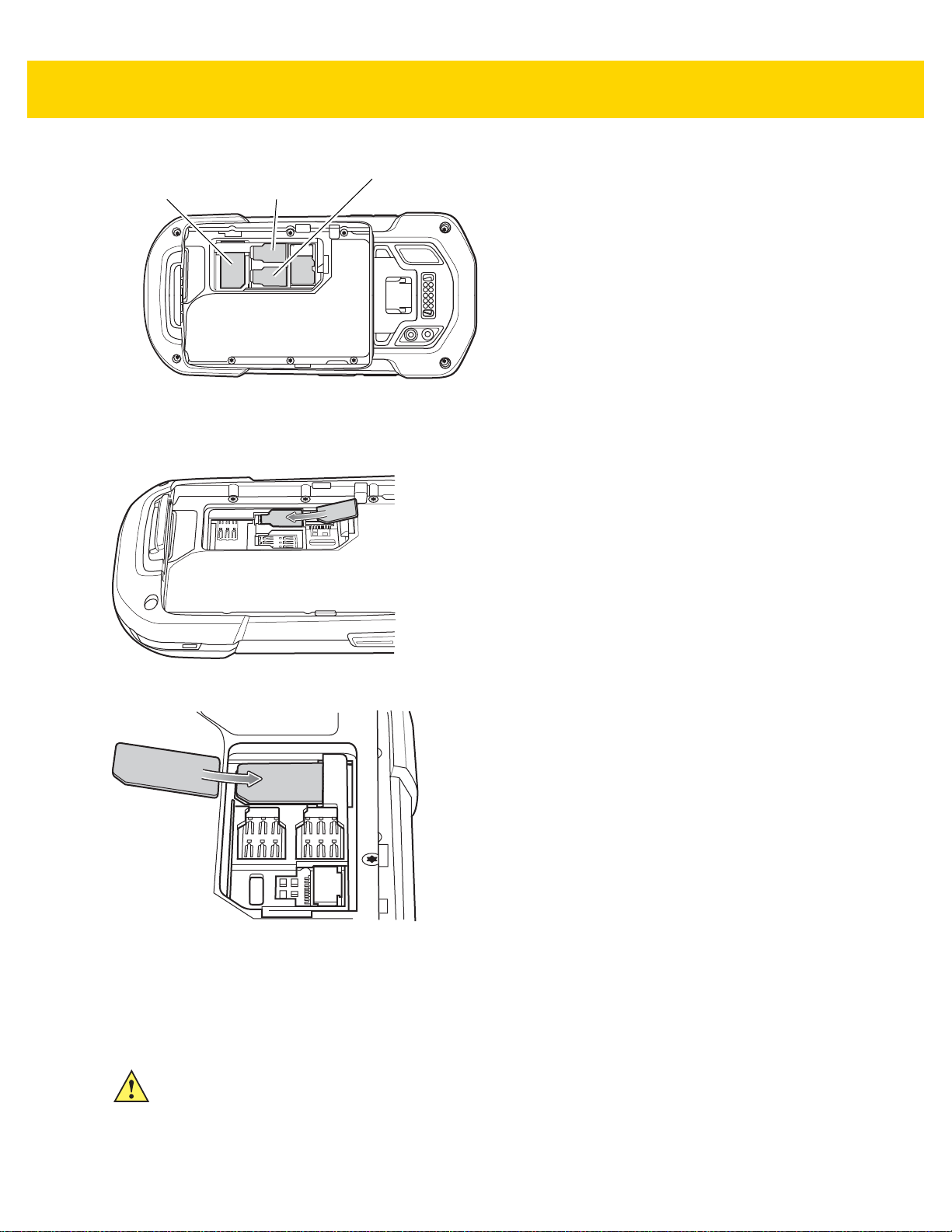
2. Insert a SIM card into the SIM slot with the cut edge toward the middle of the device and the contacts facing
down.
Figure 1-2 nano SIM Card Installation
Figure 1-3 Mini SIM Card Installation
3. Ensure that the SIM card is seated properly.
Installing the SAM Card
CAUTION For proper electrostatic discharge (ESD) precautions to avoid damaging the SIM card. Proper ESD
precautions include, but not limited to, working on an ESD mat and ensuring that the user is properly
grounded.
Page 23
Getting Started 1 - 3
Mini SAM Slot
NOTE The TC70x/TC75x contains one slot for a mini SAM card. If using a micro SAM card, a third-party adapter
is required. On the TC75x, when using a SAM card, only a nano SIM card can be used.
1. Remove access cover.
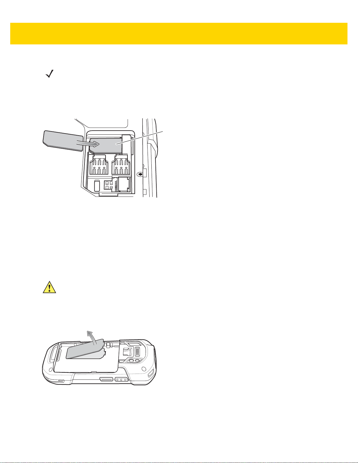
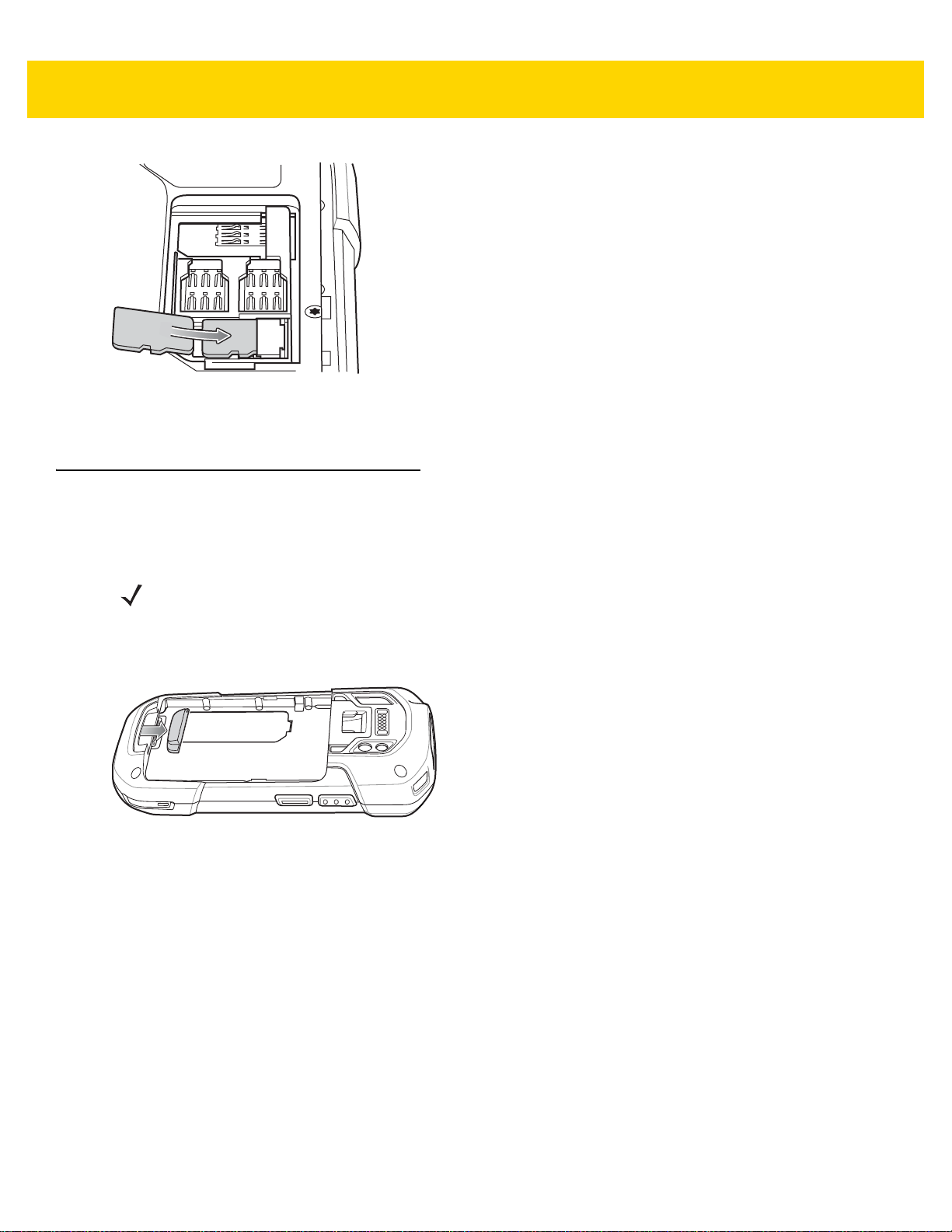
2. Insert a SAM card into the SAM slot with the cut edge toward the middle of the device and the contacts facing
down.
Figure 1-4 SAM Card Installation
3. Ensure that the SAM card is seated properly.
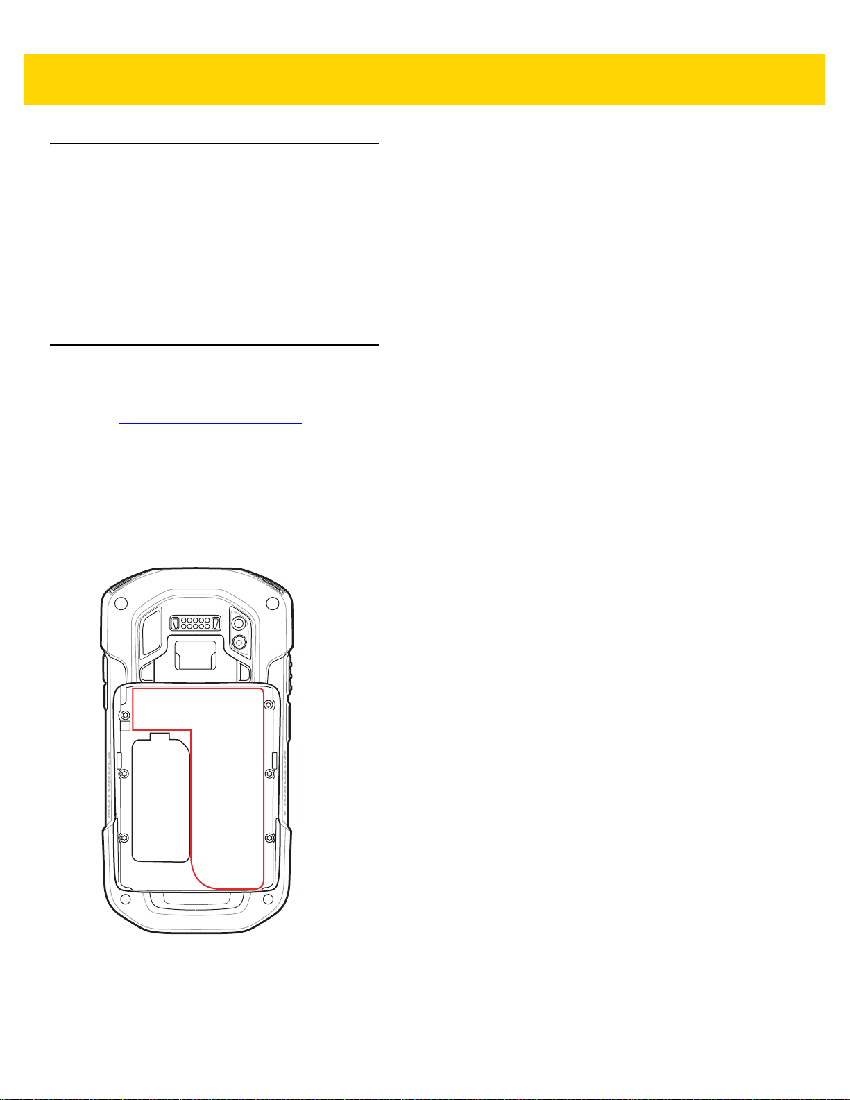
Installing a microSD Card
The microSD card slot provides secondary non-volatile storage. The slot is locate d under the batte ry pack. Refer to
the documentation provided with the card for more information, and follow the manufacturer’s recommendations for
use.
CAUTION For proper electrostatic discharge (ESD) precautions to avoid damaging the SIM card. Proper ESD
precautions include, but not limited to, working on an ESD mat and ensuring that the user is properly
grounded.
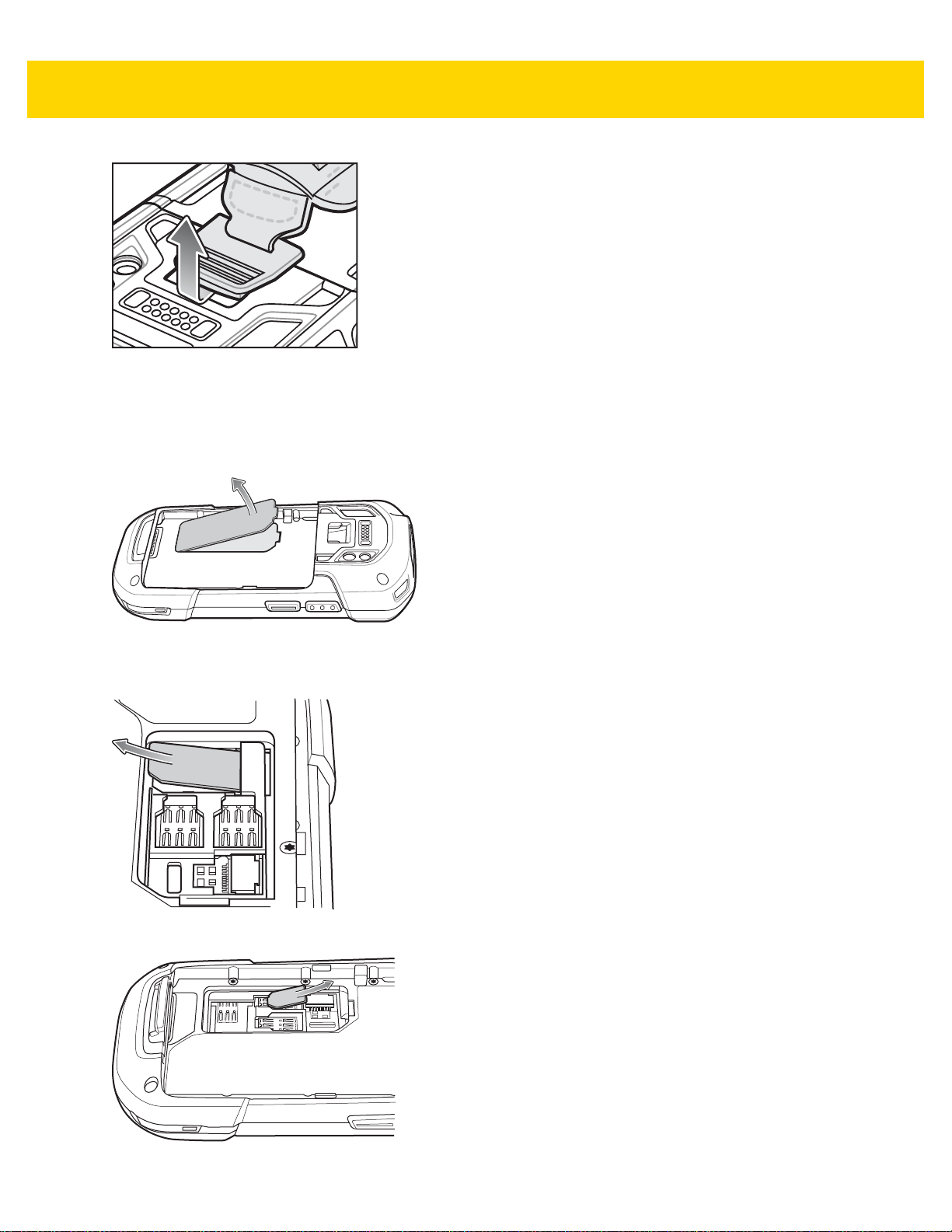
1. Remove the hand strap, if installed.
2. Lift the access door.
Figure 1-5 Lift Access Door
3. Insert the microSD card into the card holder door ensuring that the card slides into the holding tabs on each
side of the door.
Page 24
1 - 4 TC70x/TC75x Integrator Guide
Figure 1-6 Insert microSD Card in Holder
4. Re-install the access door.
Installing the Hand Strap and Battery
To install the hand strap and battery:
NOTE Installation of the hand strap is optional. Skip this section if not installing the hand strap.
1. Remove the hand strap filler from the hand strap slot. Store the hand strap filler in a safe place for future
replacement.
Figure 1-7 Remove Filler
2. Insert the hand strap plate into the hand strap slot.
Page 25

Getting Started 1 - 5
Figure 1-8 Insert Hand Strap
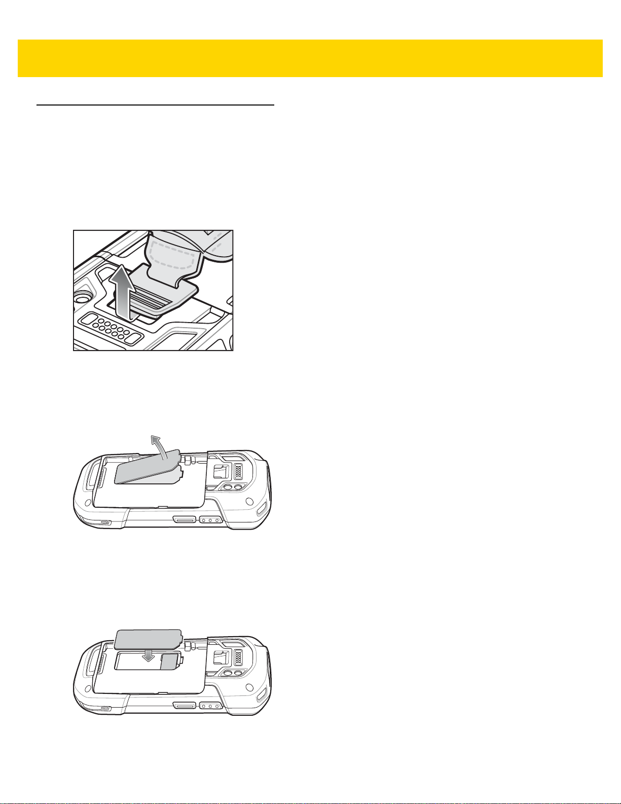
3. Insert the battery, bottom first, into the battery compartment in the back of the TC70x/TC75x.
Figure 1-9 Insert Bottom of Battery into Battery Compartment
4. Press the battery down into the battery compartment until the battery release latches snap into place.
Figure 1-10 Press Down on Battery
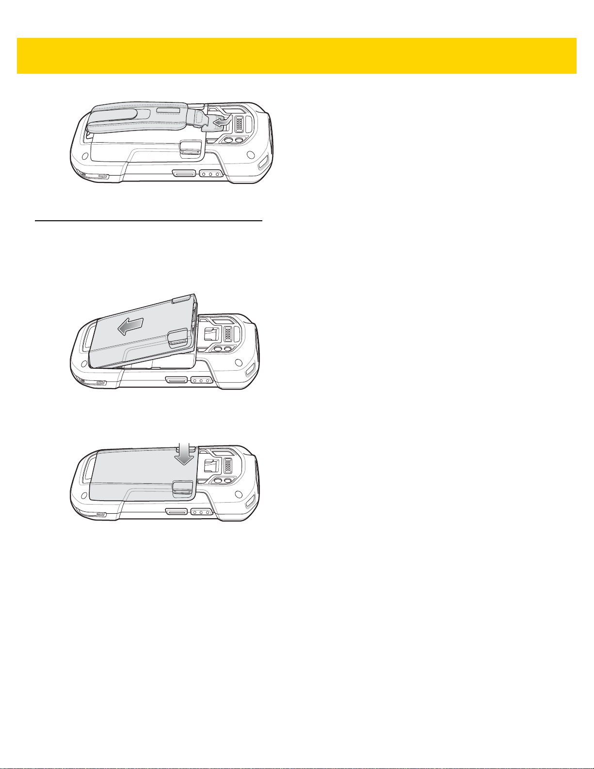
5. Place hand strap clip into hand strap mounting slot and pull down until it snaps into place.
Page 26
1 - 6 TC70x/TC75x Integrator Guide
Figure 1-11 Secure Hand Strap Clip
Installing the Battery
To install the battery:
1. Insert the battery, bottom first, into the battery compartment in the back of the TC70x/TC75x.
Figure 1-12 Insert Bottom of Battery into Battery Compartment
2. Press the battery down into the battery compartment until the battery release latches snap into place.
Figure 1-13 Press Down on Battery
Charging the Battery
Before using the TC70x/TC75x for the first time, charge the main battery until the green Charging/Notification light
emitting diode (LED) remains lit. To charge the TC70x/TC75x, use a cable or a cradle with the appropriate power
supply . For information about the accessor ies available for the TC70x/TC75x, see Chapter 2, Accessories for more
information.
• Snap-On USB Cable
• Charging Cable Cup
• 2-Slot Charge Only Cradle
• 2-Slot USB/Ethernet Cradle
• 5-Slot Charge Only Cradle
• 5-Slot Ethernet Cradle
Page 27

Getting Started 1 - 7
• Charge Only Vehicle Cradle
• Auto Charging Cable Cup.
• Serial Cable Cup
The 4,620 mAh battery fully charges in less than five hours at room temperature.
Charge batteries in temperatures from 0 °C to 40 °C (32 °F to 104 °F). The TC70x/TC75x or accessory always
performs battery charging in a safe and intelligent manner. At higher temperatures (e.g. approximately +37 °C (+98
°F)) the TC70x/TC75x or accessory may for small periods of time alternately enable and disable battery charging
to keep the battery at acceptable temperatures. The TC70x/TC75x or accessory indicates when charging is
disabled due to abnormal temperatures via its LED.
1. To charge the main battery, connect the charging accessory to the appropr iate power source.
2. Insert the TC70x/TC75x into a cradle or attach to a cable. The TC70x/TC75x turns on and begins charging.
The Charging/Notification LED blinks amber while charging, then turns solid green when fully charged.
Charging Indicators
Table 1-1 Charging/Notification LED Charging Indicators
State Indication
Off The device is not charging. The device is not inserted correctly in the cradle or
Slow Blinking Amber (1 blink
every 4 seconds)
Solid Green Charging complete.
Fast Blinking Amber (2
blinks/second)
Slow Blinking Red (1 blink
every 4 seconds)
Solid Red Charging complete but the battery is at end of useful life.
Fast Blinking Red (2
blinks/second)
Replacing the Battery
connected to a power source. Charger/cradle is not powered.
The device is charging.
Charging error, e.g.:
• Te mperature is too low or too high.
• Charging has gone on too long without completion (typically eight hours).
Thedevice is charging but the battery is at end of useful life.
Charging error but the battery is at end of useful life., e.g.:
• Te mperature is too low or too high.
• Charging has gone on too long without completion (typically eight hours).
CAUTION Do not add or remove SIM, SAM or microSD card during battery replacement.
1. Remove any accessory attached to the device.
2. For devices with the Battery Swap mode feature:
a. Press the Power button until the menu appears.
b. Touch Battery Swap.
Page 28
1 - 8 TC70x/TC75x Integrator Guide
c. Follow the on-screen instructions.
d. Wait for the LED to turn off.
3. For devices without Battery Swap mode feature:
a. Press the Power button until the menu appears.
b. Touch Power off.
c. Touch OK.
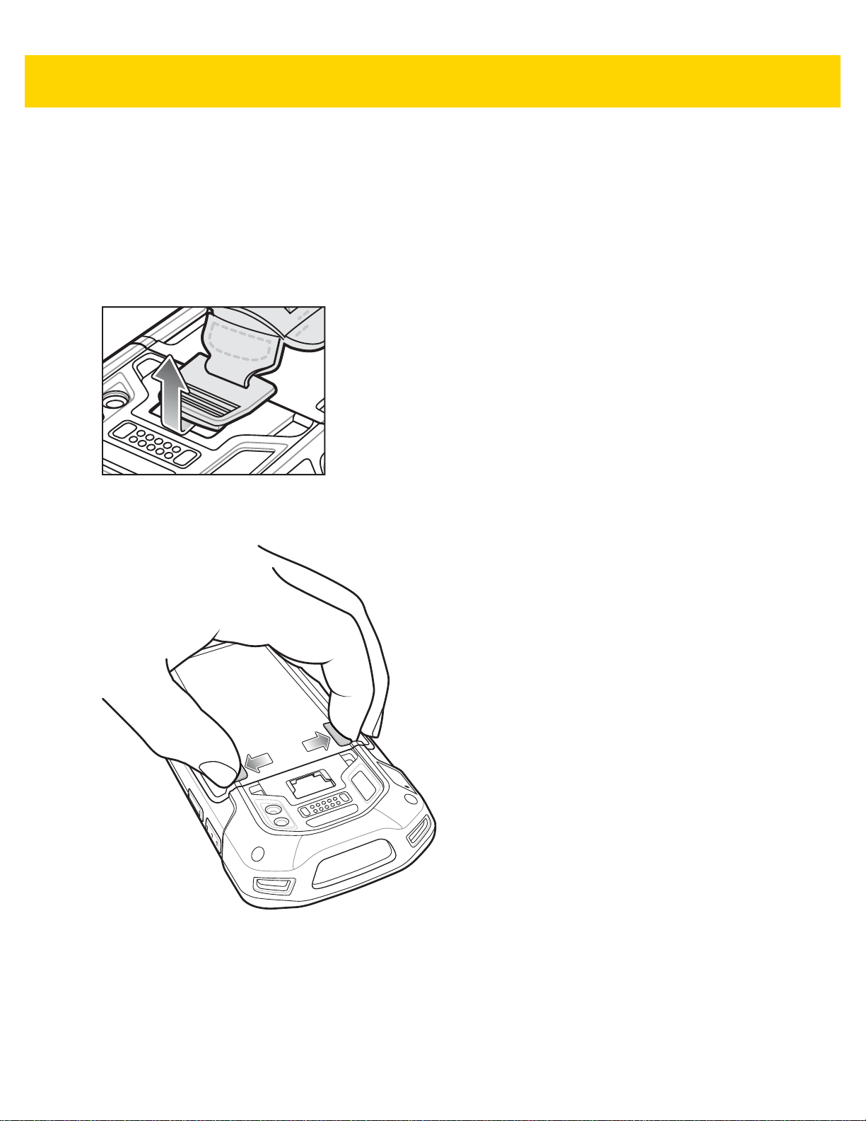
4. If hand strap is attached, slide the hand strap clip up toward the top of the TC70x/TC75x and then lift.
Figure 1-14 Remove Hand Strap Clip
5. Press the two battery latches in.
Figure 1-15 Press Battery Latches
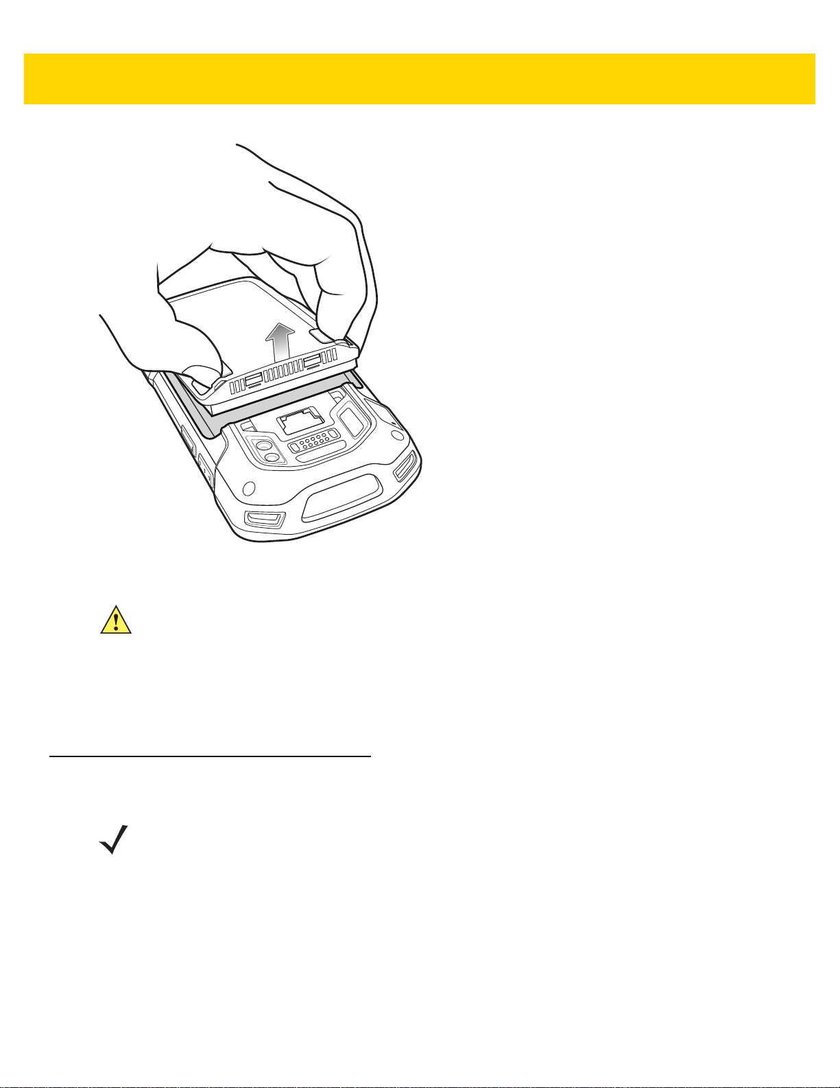
6. Lift the battery from the TC70x/TC75x.
Page 29
Getting Started 1 - 9
Figure 1-16 Lift the Battery
CAUTION Replace the battery within two minutes. After two minutes the device reboots and data may be lost.
7. Insert the replacement battery, bottom first, into the battery compartment in the back of the TC70x/TC75x.
8. Press the battery down until the battery release latch snaps into place.
9. Replace the hand strap, if required.
10. Press and hold the Power button to turn on the TC70x/TC75x.
Replacing the SIM or SAM Card
NOTE SIM replacement applies to TC75x only.
To replace the SIM or SAM card:
1. Press and hold the Power button until the menu appears.
2. Touch Power off.
3. Touch OK.
4. If hand strap is attached, slide the hand strap clip up toward the top of the TC70x/TC75x and then lift.
Page 30
1 - 10 TC70x/TC75x Integrator Guide
Figure 1-17 Remove Hand Strap Clip
5. Press the two battery latches in.
6. Lift the battery from the TC70x/TC75x.
7. Lift the access door.
Figure 1-18 Remove Access Door
8. Remove card from holder.
Figure 1-19 Remove Mini SIM/SAM Card
Figure 1-20 Remove Nano SIM Card
Page 31

9. Insert the replacement card.
Figure 1-21 Insert Mini SIM/SAM Card
Getting Started 1 - 11
Figure 1-22 Insert Nano SIM Card
10. Replace the access door.
Figure 1-23 Replace Access Door
11. Press the access door down and ensure that it is properly seated.
12. Insert the battery, bottom first, into the battery compartment in the back of the TC70x/TC75x.
13. Press the battery down until the battery release latch snaps into place.
14. Replace the hand strap, if required.
15. Press and hold the Power button to turn on the TC70x/TC75x.
Page 32
1 - 12 TC70x/TC75x Integrator Guide
Replacing the microSD Card
To replace the microSD card:
1. Press the Power button until the menu appears.
2. Touch Power off.
3. Touch OK.
4. If hand strap is attached, slide the hand strap clip up toward the top of the TC70x/TC75x and then lift.
Figure 1-24 Remove Hand Strap Clip
5. Press the two battery latches in.
6. Lift the battery from the TC70x/TC75x.
7. Lift the access door.
Figure 1-25 Remove Access Door
8. Remove microSD card from holder.
9. Press the access door down and ensure that it is properly seated.
10. Insert the replacement microSD card.
11. Replace the access door.
Figure 1-26 Replace Access Door
12. Insert the battery, bottom first, into the battery compartment in the back of the TC70x/TC75x.
Page 33

13. Press the battery down until the battery release latch snaps into place.
14. Replace the hand strap, if required.
15. Press and hold the Power button to turn on the TC70x/TC75x.
Resetting the Device
There are four reset functions:
• Soft reset
• Hard reset
• Enterprise reset. See Performing an Enterprise Reset on page 6-11.
• Factory reset. See Performing a Factory Reset on page 6-13.
Performing a Soft Reset
Perform a soft reset if applications stop responding.
1. Press and hold the Power button until the menu appears.
2. Touch Reset.
3. The device reboots.
Getting Started 1 - 13
Performing a Hard Reset
CAUTION Performing a hard reset with a SD card installed in the TC70x/TC75x may cause damage or data
corruption to the SD card.
Perform a hard reset if the TC70x/TC75x stops responding.
1. Simultaneously press the Power, Scan and Volume Up buttons for at least four seconds.
2. When the screen turns off, release the buttons.
3. The TC70x/TC75x reboots.
Page 34

1 - 14 TC70x/TC75x Integrator Guide
Page 35

CHAPTER 2 ACCESSORIES
Introduction
This chapter provides information for using the accessories for the device.
Accessories
This table lists the accessories available for the TC70x/TC75x.
Table 2-1 Accessories
Accessory Part Number Description
Cradles
2-Slot Charge Only
Cradle
2-Slot USB/Ethernet
Cradle
5-Slot Charge Only
Cradle
5-Slot Ethernet Cradle CRD-TC7X-SE5EU1–01 Provides device charging and provides Ethernet
Cradle Mount BRKT-SCRD-SMRK-01 Mounts the 5-Slot Charge Only Cradle, 5-Slot Ethernet
CRD-TC7X-SE2CPP-01 Provides device and spare battery charging. Use with
power supply, p/n PWRS-14000-148R.
CRD-TC7X-SE2EPP-01 Provides device and spare battery charging and USB
communication with a host computer and Ethernet
communication with a network. Use with power supply,
p/n PWRS-14000-148R.
CRD-TC7X-SE5C1-01 Charges up to five devices. Use with power supply, p/n
PWRS-14000-241R and DC line cord, p/n
50-16002-029R. Can accommodate one 4-Slot Battery
Charger using the Battery Adapter Cup.
communication for up to five devices. Use with power
supply, p/n PWRS-14000-241R and DC line cord, p/n
50-16002-029R. Can accommodate one 4-Slot Battery
Charger using the Battery Adapter Cup.
Cradle, and 4-Slot Battery Charger to a wall or rack.
Page 36

2 - 2 TC70x/TC75x Integrator Guide
Table 2-1 Accessories (Continued)
Accessory Part Number Description
Batteries and Chargers
4,620 mAh
PowerPrecision+ battery
4-Slot Spare Battery
Charger
Battery Charger Adapter
Cup
Vehicle Solutions
Charging Cable Cup CHG-TC7X-CLA1-01 Provides power to the device from a cigarette lighter
Charge Only Vehicle
Cradle
Cigarette Light Adapter
Auto Charge Cable
Hard-wire Auto Charge
Cable
RAM Mount RAM-B-166U Provides window mounting option for the Vehicle
BTRY-TC7X-46MPP-01
BTRY-TC7X-46MPP-10
SAC-TC7X-4BTYPP-01 Charges up to four battery packs. Use with power
CUP-SE-BTYADP1-01 Allows for one 4-Slot Battery Charger to be charged
CRD-TC7X-CVCD1-01 Charges and securely holds the device. Requires
CHG-AUTO-CLA1-01 Provides power to the Vehicle Cradle from a cigarette
CHG-AUTO-HWIRE1-01 Provides power to the Vehicle Cradle from the vehicle's
Replacement battery (single pack).
Replacement battery (10–pack).
supply, p/n PWRS-14000-148R.
and docked on the left most slot of the 5-Slot cradles
(maximum one per cradle).
socket.
power cable CHG-AUTO-CLA1-01 or
CHG-AUTOHWIRE1-01, sold separately.
lighter socket.
power panel.
Cradle. RAM Twist Lock Suction Cup with Double
Socket Arm and Diamond Base Adapter. Overall
Length: 6.75”.
RAM Mount Base RAM-B-238U RAM 2.43" x 1.31" Diamond Ball base with 1" ball.
Charge and Communication Cables
Charging Cable Cup CHG-TC7X-CBL1-01 Provides power to the device. Use with power supply,
p/n PWRS-14000-249R, sold separately.
Snap-On USB Cable CBL-TC7X-CBL1-01 Provides power to the device and USB communication
with a host computer. Use with power supply, p/n
PWRS-14000-249R, sold separately.
Snap-On Serial Cable CBL-TC7X-SERL1-01 Provides power and serial communication with a host
computer. Use with power supply, p/n
PWRS-14000-249R, sold separately.
Snap-On DEX Cable CBL-TC7X-DEX1-01 Provides electronic data exchange with devices such
as vending machines.
Audio Accessories
Premium Headset RCH51 Premium Rugged headset.
3.5 mm Audio Adapter ADP-TC7X-AUD35-01 Snaps onto the device and provides audio to a wired
headset with 3.5 mm plug.
Page 37

Table 2-1 Accessories (Continued)
Accessory Part Number Description
3.5 mm Headset HDST-35MM-PTVP-01 Use for PTT and VoIP calls.
Accessories 2 - 3
3.5 mm Quick
Disconnect
Adapter Cable
Scanning
Trigger Handle TRG-TC7X-SNP1-01 Adds gun-style handle with a scanner trigger for
Carrying Solutions
Soft Holster SG-TC7X-HLSTR1-01 TC7X soft holster.
Rigid Holster SG-TC7X-RHLSTR1-01 TC7X rigid holster.
Hand Strap SG-TC7X-HSTRP1-03 Replacement hand strap with hand strap mounting clip
Stylus and Coiled Tether SG-TC7X-STYLUS-03 TC7X stylus with coiled tether (3-pack).
Power Supplies
Power Supply PWRS-14000-249R Provides power to the device using the Snap-On USB
Power Supply PWRS-14000-148R Provides power to the 2–Slot cradles and 4-Slot Spare
ADP-35M-QDCBL1-01 Provides connection to the 3.5 mm Headset.
comfortable and productive scanning.
(3–pack).
Cable, Snap-on Serial Cable or Charging Cable Cup.
Requires AC line cord.
Battery Charger. Requires AC line cord.
Power Supply PWRS-14000-241R Provides power to the 5-Slot Charge Only cradle and
the 5-Slot Ethernet Cradle. Requires DC Line Cord, p/n
50–16002–029R and country specific three wire
grounded AC line cord sold separately.
DC Line Cord 50-16002-029R Provides power from the power supply to the 5-Slot
Charge Only Cradle and 5-Slot Ethernet Cradle .
Page 38
2 - 4 TC70x/TC75x Integrator Guide
Spare battery Charging LED
Power LED
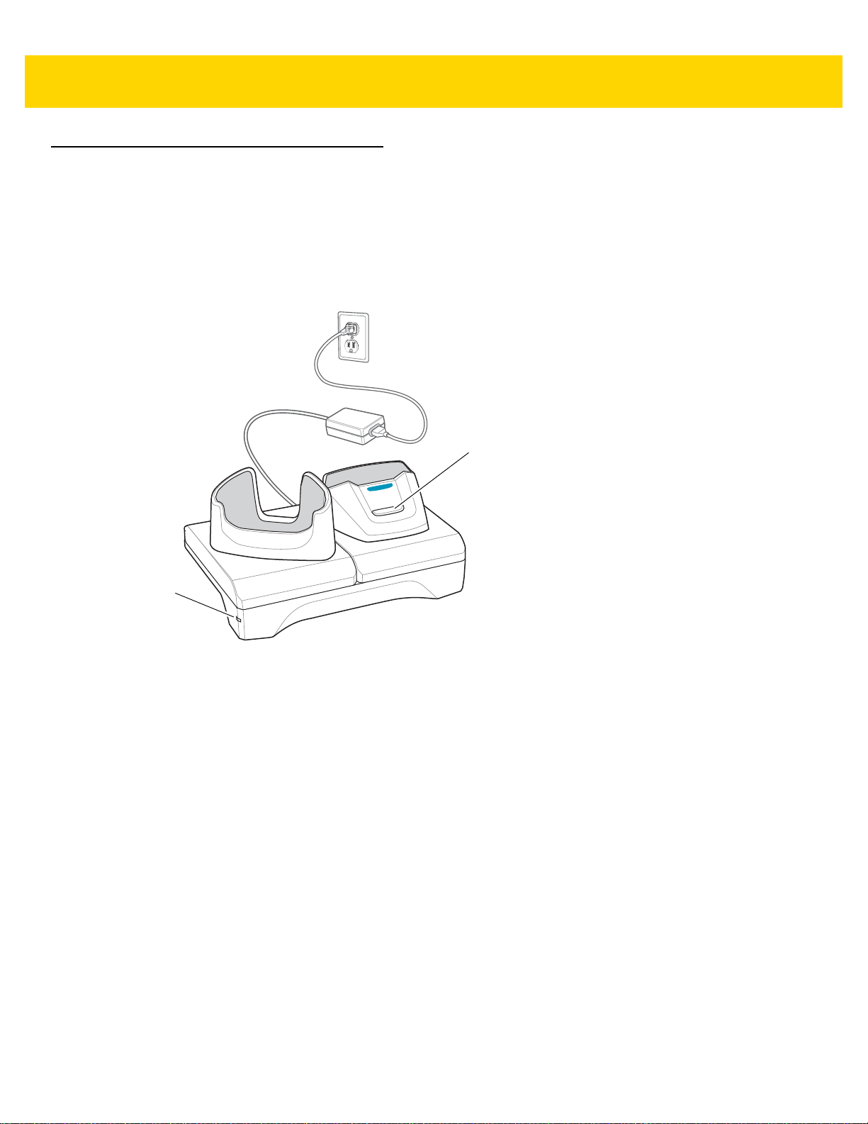
2-Slot Charge Only Cradle
The 2-Slot Charge Only Cradle:
• Provides 5 VDC power for operating the device.
• Charges the device’s battery.
• Charges a spare battery.
Figure 2-1 2–Slot Charge Only Cradle
Page 39

Setup
Accessories 2 - 5
Figure 2-2 2–Slot Charge Only Cradle
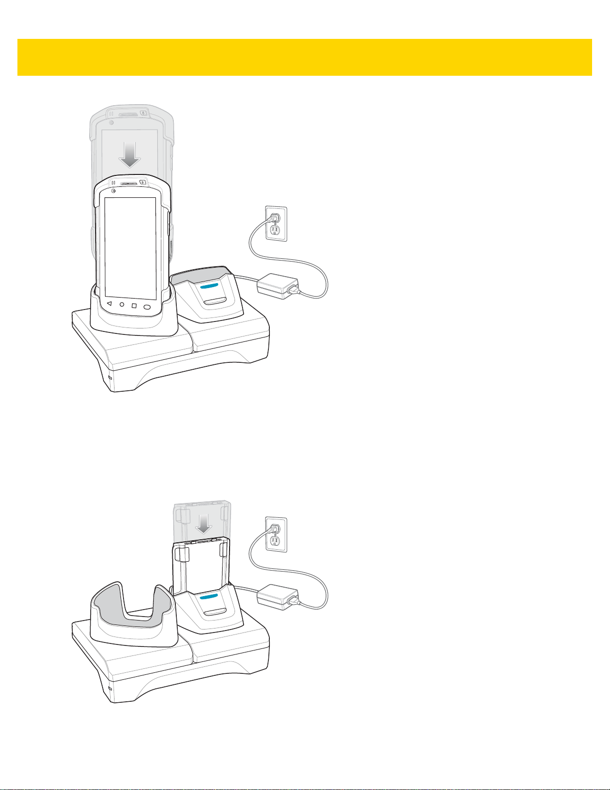
Charging the Device
1. Insert the device into the slot to begin charging.
Page 40
2 - 6 TC70x/TC75x Integrator Guide
Figure 2-3 Battery Charging
2. Ensure the device is seated properly.
Charging the Spare Battery
1. Insert the battery into the right slot to begin charging.
Figure 2-4 Spare Battery Charging
2. Ensure the battery is seated properly.
Page 41

Battery Charging
Main Battery Charging
The device’s Charging/Notification LED indicates the status of the battery charging in the device.
The 4,620 mAh battery fully charges in less than five hours at room temperature.
Spare Battery Charging
The Spa re battery Charging LED on the cup indicates the status of the spare battery charging.
The 4,620 mAh battery fully charges in less than five hours at room temperature.
Table 2-2 Spare Battery Charging LED Indicators
LED Indication
Slow Blinking Amber Spare battery is charging.
Solid Green Charging complete.
Accessories 2 - 7
Fast Blinking Amber Error in charging; check placement of spare battery.
Slow Blinking Red Spare battery is charging and battery is at the end of
useful life.
Solid Red Charging complete and battery is at the end of useful
life.
Fast Blinking Red Error in charging; check placement of spare battery and
battery is at the end of useful life.
Off No spare battery in slot; spare battery not placed
correctly; cradle is not powered.
Charging Temperature
Charge batteries in temperatures from 0 °C to 40 °C (32 °F to 104 °F). The device or cradle always performs
battery charging in a safe and intelligent manner. At higher temperatures (e.g. approximately +37 °C (+98 °F)) the
device or cradle may for small periods of time alternately enable and disable battery charging to keep the battery at
acceptable temperatures. The device and cradle indicates when charging is disabled due to abnormal
temperatures via its LED.
Page 42

2 - 8 TC70x/TC75x Integrator Guide
Spare Battery Charging LED
Power LED
2-Slot USB/Ethernet Cradle
The 2-Slot USB/Ethernet Cradle:
• Provides 5.0 VDC power for operating the device.
• Charges the device’s battery.
• Charges a spare battery.
• Connects the device to an Ethernet network.
• Provides communication to a host computer using a USB cable.
NOTE Remove all attachments on the device, except the hand strap, before place onto the cradle.
Figure 2-5 2-Slot USB/Ethernet Cradle
Page 43

Setup
Accessories 2 - 9
Figure 2-6 2–Slot USB/Ethernet Cradle
Charging the Device
1. Place the bottom of the device into the base.
Page 44

2 - 10 TC70x/TC75x Integrator Guide
Figure 2-7 Battery Charging
2. Rotate the top of the device until the connector on the back of the device mates with the connector on the
cradle.
3. Ensure the device is connected properly . The charging Charging/Notification LED on the device begins blinking
amber indicating that the device is charging.
Charging the Spare Battery
1. Insert the battery into the right slot to begin charging.
Page 45

Figure 2-8 Spare Battery Charging
Accessories 2 - 11
2. Ensure the battery is seated properly.
Battery Charging
Main Battery Charging
The device’s Charging/Notification LED indicates the status of the battery charging in the device.
The 4,620 mAh battery fully charges in less than five hours at room temperature.
Spare Battery Charging
The Spa re battery Charging LED on the cup indicates the status of the spare battery charging.
The 4,620 mAh battery fully charges in less than five hours at room temperature.
Table 2-3 Spare Battery Charging LED Indicators
LED Indication
Slow Blinking Amber Spare battery is charging.
Solid Green Charging complete.
Fast Blinking Amber Error in charging; check placement of spare battery.
Slow Blinking Red Spare battery is charging and battery is at the end of
useful life.
Solid Red Charging complete and battery is at the end of useful
life.
Page 46

2 - 12 TC70x/TC75x Integrator Guide
1
2
Table 2-3 Spare Battery Charging LED Indicators (Continued)
LED Indication
Fast Blinking Red Error in charging; check placement of spare battery and
Off No spare battery in slot; spare battery not placed
Charging Temperature
Charge batteries in temperatures from 0 °C to 40 °C (32 °F to 104 °F). The device or cradle always performs
battery charging in a safe and intelligent manner. At higher temperatures (e.g. approximately +37 °C (+98 °F)) the
device or cradle may for small periods of time alternately enable and disable battery charging to keep the battery at
acceptable temperatures. The device and cradle indicates when charging is disabled due to abnormal
temperatures via its LED.
USB/Ethernet Communication
The 2–Slot USB/Ethernet Cradle provides both Ethernet communication with a network and USB communication
with a host computer. Prior to using the cradle for Ethernet or USB communication. Ensure that the switch on the
USB/Ethernet module is set properly.
battery is at the end of useful life.
correctly; cradle is not powered.
Turn the cradle over to view the module.
Figure 2-9 2–Slot USB/Ethernet Cradle Module Switch
For Ethernet communication, slide the switch to the position.
For USB communication, slide the switch to the position.
Place the switch in the center position to disable communications.
Ethernet LED Indicators
There are two LEDs on the USB/Ethernet Module RJ-45 connector. The green LED lights to indicate that the
transfer rate is 100 Mbps. When the LED is not lit the transfer rate is 10 Mbps. The yellow LED blinks to indicate
activity, or stays lit to indicate that a link is established. When it is not lit it indicates that there is no link.
Figure 2-10 LED Indicators
Page 47

Accessories 2 - 13
Table 2-4 USB/Ethernet Module LED Data Rate Indicators
Data Rate (1) Amber LED (2) Green LED
100 Mbps On/Blink On
10 Mbps On/Blink Off
Ethernet Settings
The following settings can be configured when using Ethernet communication:
• Proxy Settings
• Static IP.
Configuring Ethernet Proxy Settings
The TC70x/TC75x includes Ethernet cradle drivers. After inserting the TC70x/TC75x, configure the Ethernet
connection:
1. Touch > .
2. Touch Ethernet.
3. Place the TC70x/TC75x into the Ethernet cradle slot.
4. Slide the switch to the ON position.
5. Touch and hold Eth0 until the menu appears.
6. Touch Modify Proxy.
7. Touch the Proxy drop-down list and select Manual.
Figure 2-11 Ethernet Proxy Settings
8. In the Proxy hostname field, enter the proxy server address.
9. In the Proxy port field, enter the proxy server port number.
NOTE When entering proxy addresses in the Bypass proxy for field, do not use spaces or carriage returns
between addresses.
Page 48

2 - 14 TC70x/TC75x Integrator Guide
10. In the Bypass proxy for text box, enter addresses for web sites that do not require to go through the proxy
server. Use the separator “|” between addresses.
11. Touch MODIFY.
12. Touch .
Configuring Ethernet Static IP Address
The TC70x/TC75x includes Ethernet cradle drivers. After inserting the TC70x/TC75x, configure the Ethernet
connection:
1. Touch > .
2. Touch Ethernet.
3. Place the TC70x/TC75x into the Ethernet cradle slot.
4. Slide the switch to the ON position.
5. Touch Eth0.
6. Touch Disconnect.
7. Touch Eth0.
8. Touch and hold the IP settings drop-down list and select Static.
Figure 2-12 Static IP Settings
9. In the IP address field, enter the proxy server address.
10. If required, in the Gateway field, enter a gateway address for the device.
11. If required, in the Netmask field, enter the network mask address
12. If required, in the DNS address fields, enter a Domain Name System (DNS) addresses.
13. Touch CONNECT.
Page 49

14. Touch .
Accessories 2 - 15
Page 50
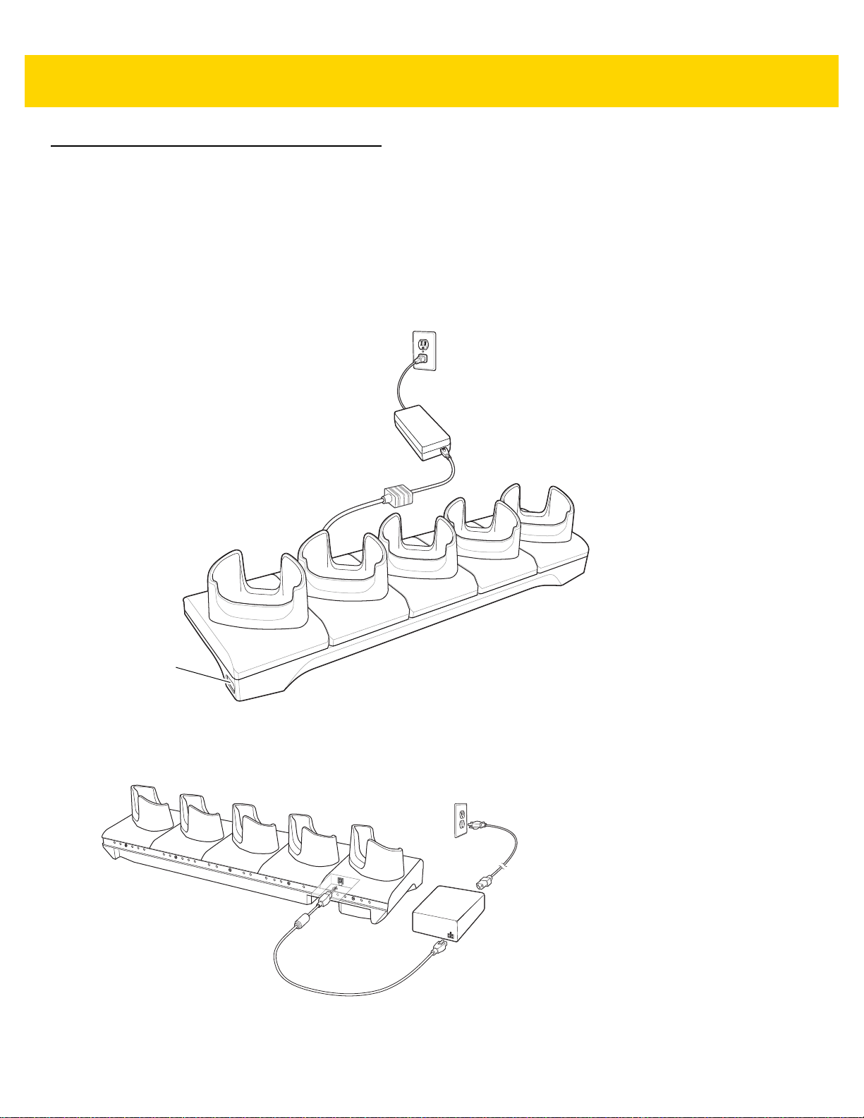
2 - 16 TC70x/TC75x Integrator Guide
Power LED
5-Slot Charge Only Cradle
The 5-Slot Charge Only Cradle:
• Provides 5 VDC power for operating the TC70x/TC75x.
• Simultaneously charges up to five devices and up to four devices and on 4-Slot Battery Charger using the
Battery Charger Adapter. See the TC70x/TC75x Integrator Guide for information on installing the 4-Slot
Battery Charger onto the cradle.
• Consists of a cradle base and cups that can be configured for various charging requirements.
Figure 2-13 5-Slot Charge Only Cradle
Setup
Figure 2-14 5-Slot Charge Only Cradle
Page 51
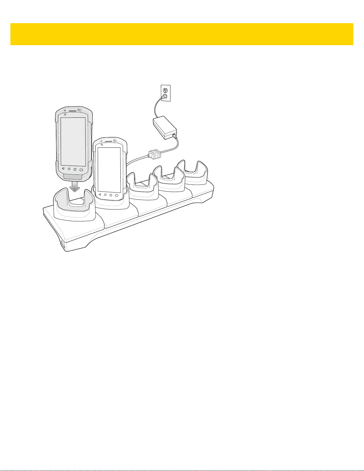
Charging the Device
1. Insert the TC70x/TC75x into a slot to begin charging.
Accessories 2 - 17
Figure 2-15 Battery Charging
Page 52
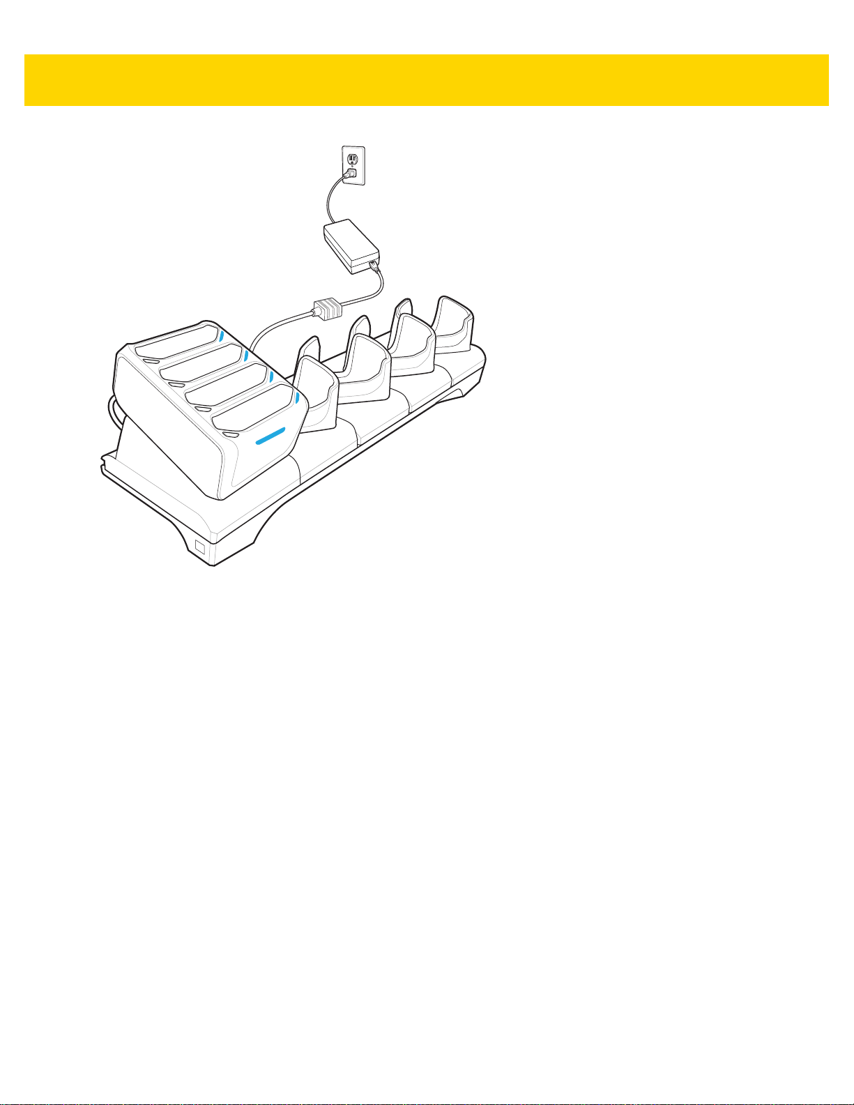
2 - 18 TC70x/TC75x Integrator Guide
Figure 2-16 5-Slot Charge Only Cradle with Four Slot Battery Charger
2. Ensure the TC70x/TC75x is seated properly.
Battery Charging
Main Battery Charging
The device’s Charging/Notification LED indicates the status of the battery charging in the device.
The 4,620 mAh battery fully charges in less than five hours at room temperature.
Charging Temperature
Charge batteries in temperatures from 0 °C to 40 °C (32 °F to 104 °F). The device always performs battery
charging in a safe and intelligent manner. At higher temperatures (e.g. approximately +37 °C (+98 °F)) the device
may for small periods of time alternately enable and disable battery charging to ke ep the battery at acceptable
temperatures. The device indicates when charging is disabled due to abnormal temperatures via its LED.
Page 53
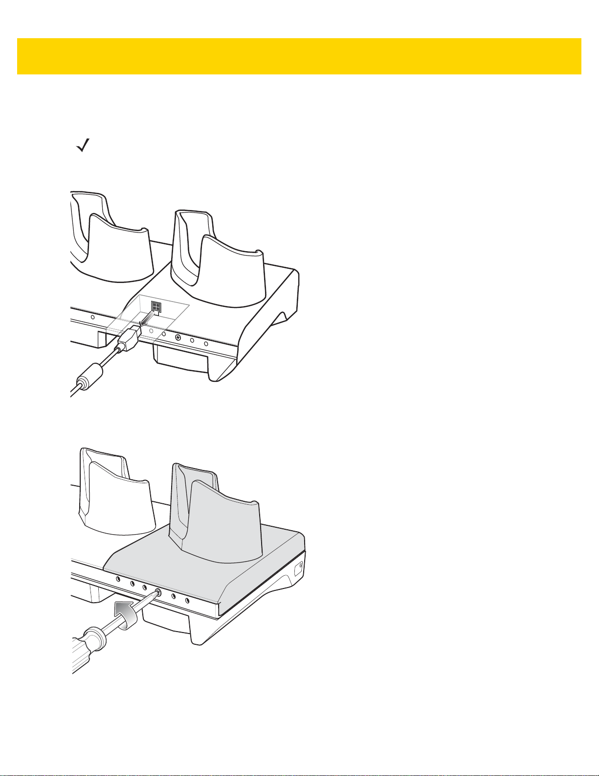
Installing the Four Slot Battery Charger
NOTE The Battery Charger must be installed in the first slot only.
1. Remove power from the cradle.
Accessories 2 - 19
Figure 2-17 Remove Power from Cradle
2. Using a Phillips screwdriver, remove the screw securing the cup to the cradle base.
Figure 2-18 Remove Screw
3. Slide the cup to the front of the cradle.
Page 54
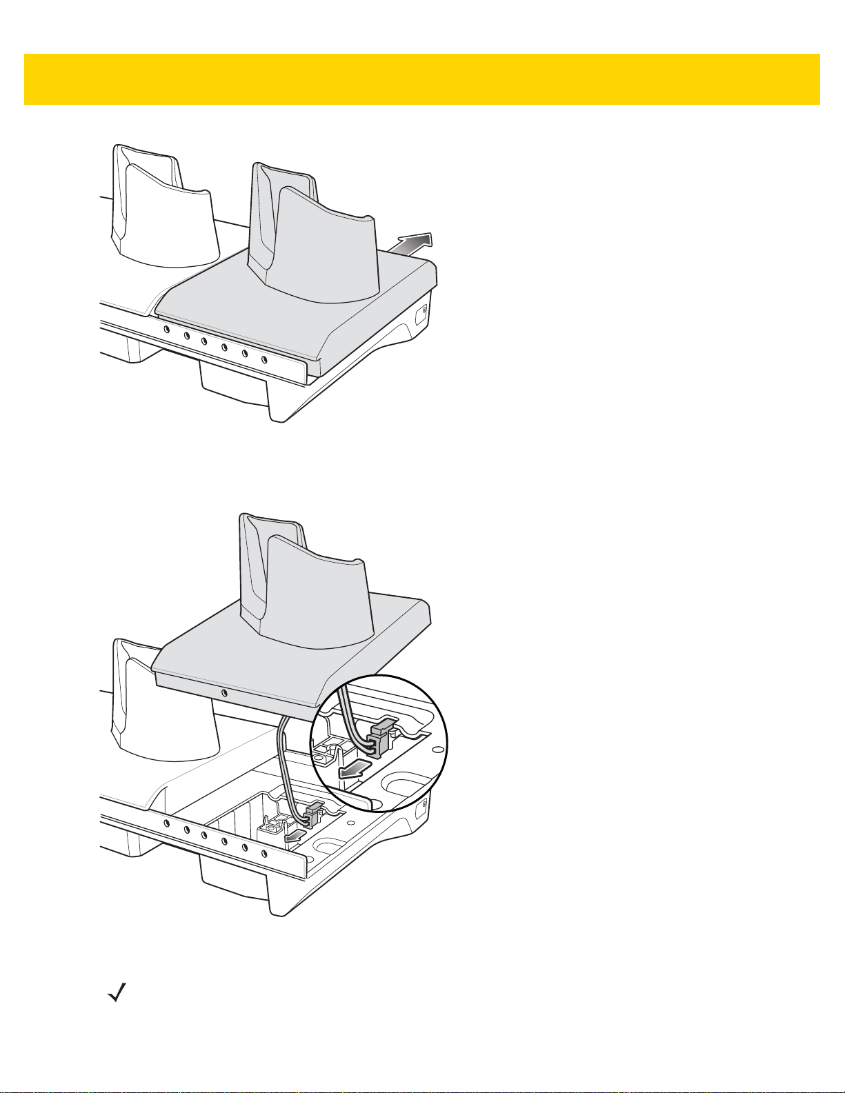
2 - 20 TC70x/TC75x Integrator Guide
Figure 2-19 Remove Cup
4. Carefully lift the cup up to expose the cup power cable.
5. Disconnect the cup power cable.
Figure 2-20 Disconnect Cup Power Cable
NOTE Place power cable into adapter to avoid pinching cable.
6. Connect the Battery Adapter power cable to the connector on the cradle.
Page 55
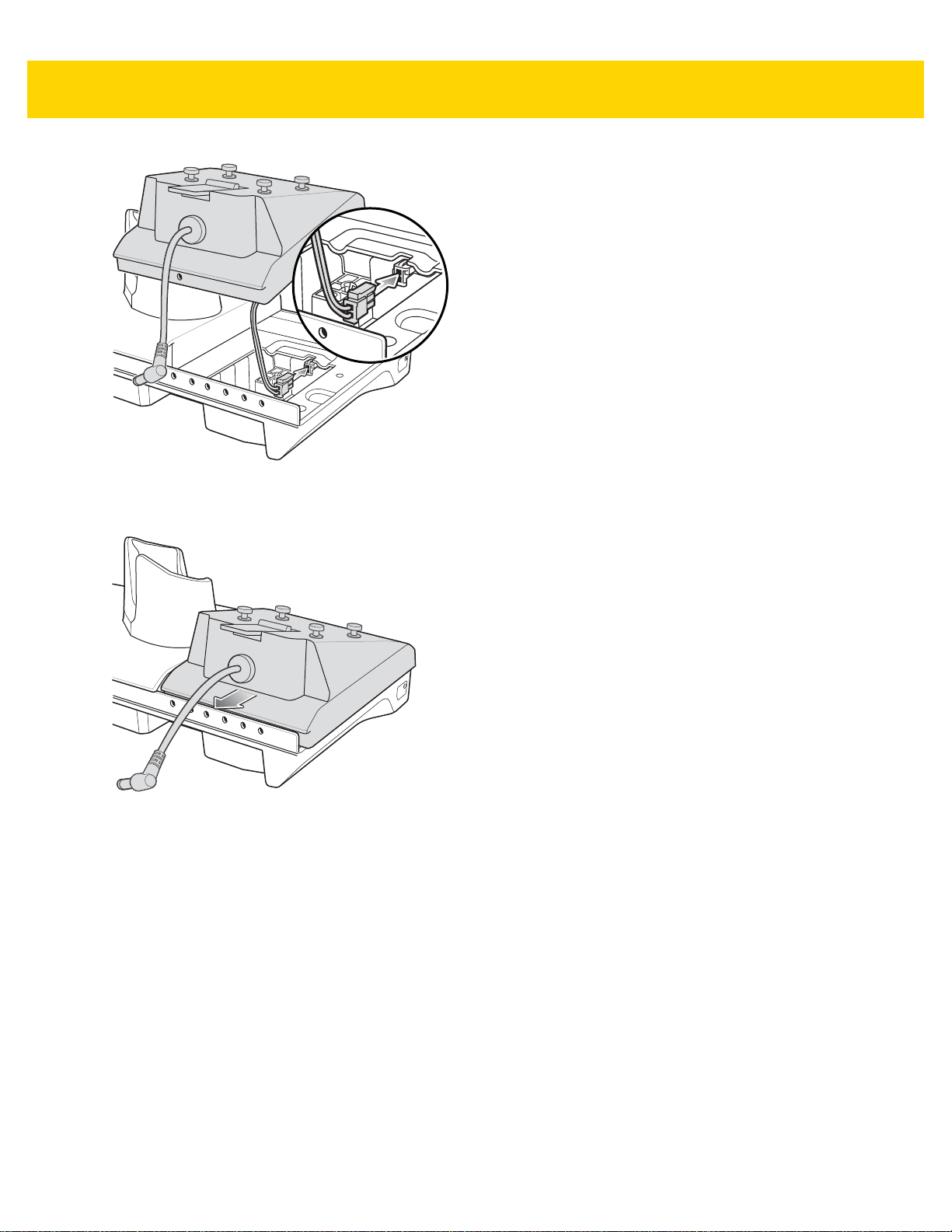
Figure 2-21 Connect Adapter Power Cable
7. Place adapter onto cradle base and slide toward rear of cradle.
Accessories 2 - 21
Figure 2-22 Install Adapter
8. Using a Phillips screwdriver, secure adapter to cradle base with screw.
Page 56

2 - 22 TC70x/TC75x Integrator Guide
Figure 2-23 Secure adapter to Cradle
9. Align mounting holes on the bottom of the Four Slot Battery Charger with the stubs on the Battery Adapter.
Figure 2-24 Install Four Slot Battery Charger
10. Slide the Four Slot battery Charger down toward the front of the cradle.
11. Connect the output power plug into the power port on the Four Slot Battery Charger.
Page 57
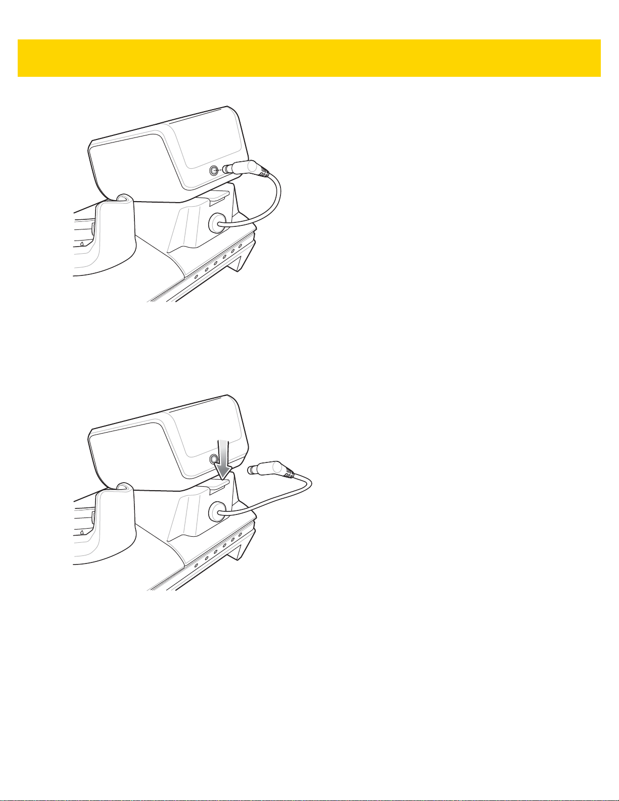
Figure 2-25 Connect Adapter Power Cable
Removing the 4-Slot Battery Charger
Accessories 2 - 23
1. Disconnect the output power plug from the 4-Slot Battery Charger.
2. At the back of the cup, press down on the release latch.
Figure 2-26 Press Release Latch
3. Slide the 4-Slot Battery Charger toward the front of the cradle.
4. Lift the 4-Slot off the cradle cup.
Page 58

2 - 24 TC70x/TC75x Integrator Guide
100/10 LED
1000 LED
5-Slot Ethernet Cradle
CAUTION Ensure that you follow the guidelines for battery safety described in Battery Safety Guidelines on page
7-1.
The 5-Slot Ethernet Cradle:
• Provides 5.0 VDC power for operating the device.
• Connects the device (up to five) to an Ethernet network.
• Simultaneously charges up to five devices or up to four devices and one 4-Slot Battery Charger using the
Battery Charger Adapter.
Figure 2-27 5-Slot Ethernet Cradle
Page 59

Setup
Connect the 5-Slot Ethernet cradle to a power source.
Figure 2-28 5-Slot Ethernet Cradle Setup
Accessories 2 - 25
Daisy-chaining Ethernet Cradles
Daisy-chain up to ten 5-Slot Ethernet cradles to connect several cradles to an Ethernet network. Use either a
straight or crossover cable. Daisy-chaining should not be attempted when the main Ethernet con nection to the first
cradle is 10 Mbps as throughput issues will almost certainly result.
To daisy-chain 5-Slot Ethernet cradles:
1. Connect power to each 5-Slot Ethernet cradle.
2. Connect an Ethernet cable to the one of the ports on the back of the first cradle and to the Ethernet switch.
3. Connect the other end of the Ethernet cable to one of the ports of the back of the second 5-Slot Ethernet
cradle.
Page 60

2 - 26 TC70x/TC75x Integrator Guide
To Switch To Power Supply
To Power SupplyTo Next
Cradle
Figure 2-29 Daisy-chaining 5-Slot Ethernet Cradles
4. Connect additional cradles as described in step 2 and 3.
Ethernet Settings
The following settings can be configured when using Ethernet communication:
• Proxy Settings
• Static IP.
Configuring Ethernet Proxy Settings
The TC70x/TC75x includes Ethernet cradle drivers. After inserting the TC70x/TC75x, configure the Ethernet
connection:
1. Touch > .
2. Touch Ethernet.
3. Place the TC70x/TC75x into the Ethernet cradle slot.
4. Slide the switch to the ON position.
5. Touch and hold Eth0 until the menu appears.
6. Touch Modify Proxy.
7. Touch the Proxy drop-down list and select Manual.
Page 61

Figure 2-30 Ethernet Proxy Settings
8. In the Proxy hostname field, enter the proxy server address.
9. In the Proxy port field, enter the proxy server port number.
Accessories 2 - 27
NOTE When entering proxy addresses in the Bypass proxy for field, do not use spaces or carriage returns
between addresses.
10. In the Bypass proxy for text box, enter addresses for web sites that do not require to go through the proxy
server. Use the separator “|” between addresses.
11. Touch MODIFY.
12. Touch .
Configuring Ethernet Static IP Address
The TC70x/TC75x includes Ethernet cradle drivers. After inserting the TC70x/TC75x, configure the Ethernet
connection:
1. Touch > .
2. Touch Ethernet.
3. Place the TC70x/TC75x into the Ethernet cradle slot.
4. Slide the switch to the ON position.
5. Touch Eth0.
6. Touch Disconnect.
7. Touch Eth0.
8. Touch and hold the IP settings drop-down list and select Static.
Page 62

2 - 28 TC70x/TC75x Integrator Guide
Figure 2-31 Static IP Settings
9. In the IP address field, enter the proxy server address.
10. If required, in the Gateway field, enter a gateway address for the device.
11. If required, in the Netmask field, enter the network mask address
12. If required, in the DNS address fields, enter a Domain Name System (DNS) addresses.
13. Touch CONNECT.
14. Touch .
LED Indicators
There are two green LEDs on the side of the cradle. These g reen LEDs lig ht and b link to indicate th e da ta transfer
rate.
Table 2-5 LED Data Rate Indicators
Data Rate 1000 LED 100/10 LED
1 Gbps On/Blink Off
100 Mbps Off On/Blink
10 Mbps Off On/Blink
Charging the Device
1. Insert the TC70x/TC75x into a slot to begin charging.
Page 63

Accessories 2 - 29
Figure 2-32 Battery Charging
2. Ensure the TC70x/TC75x is seated properly.
Page 64
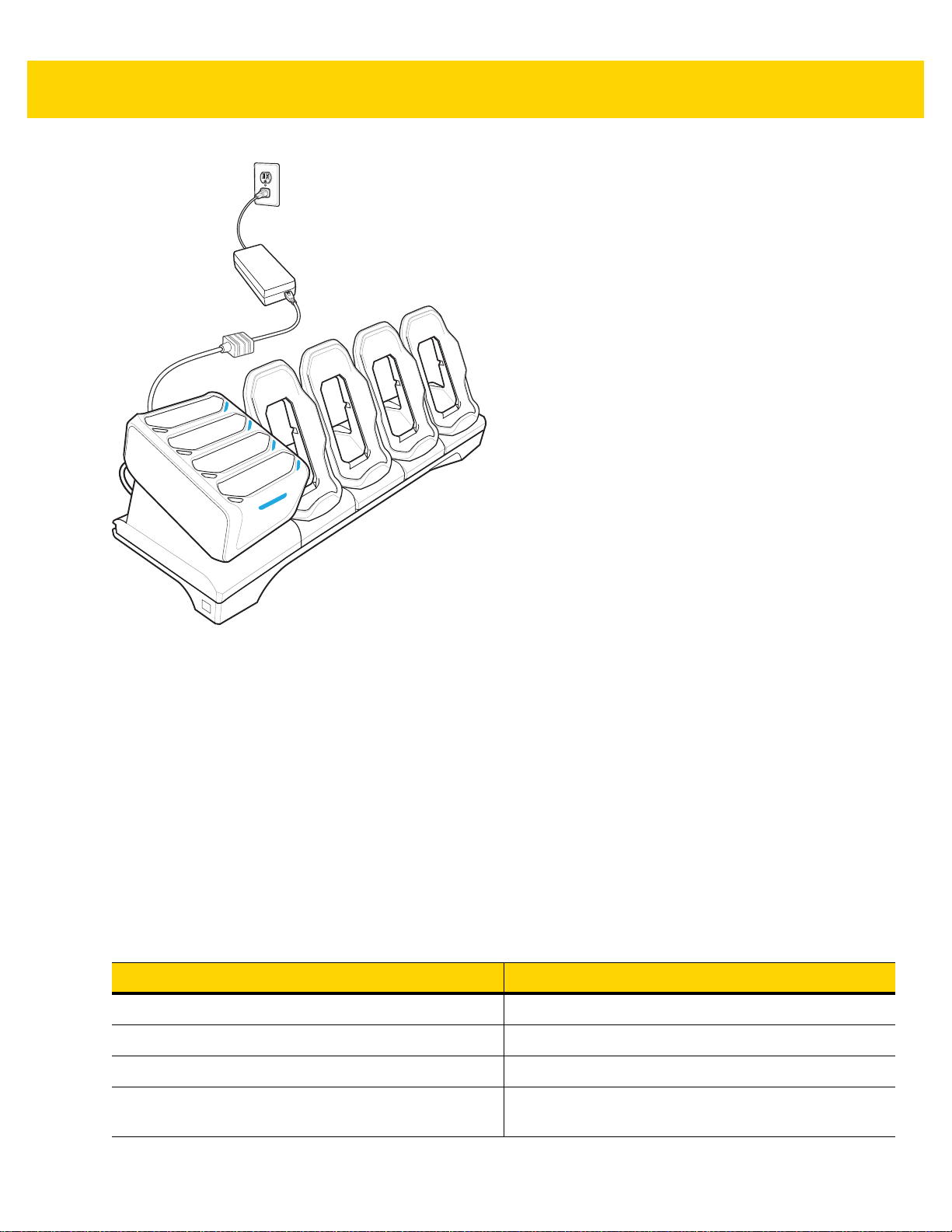
2 - 30 TC70x/TC75x Integrator Guide
Figure 2-33 5-Slot Ethernet Cradle with 4-Slot Battery Charger
Battery Charging
Main Battery Charging
The device’s Charging/Notification LED indicates the status of the battery charging in the device.
The 4,620 mAh battery fully charges in less than sixfive hours at room temperature.
Spare Battery Charging
The Spa re battery Charging LED on the cup indicates the status of the spare battery charging.
The 4,620 mAh battery fully charges in less than five hours at room temperature.
Table 2-6 Spare Battery Charging LED Indicators
LED Indication
Slow Blinking Amber Spare battery is charging.
Solid Green Charging complete.
Fast Blinking Amber Error in charging; check placement of spare battery.
Slow Blinking Red Spare battery is charging and battery is at the end of
useful life.
Page 65
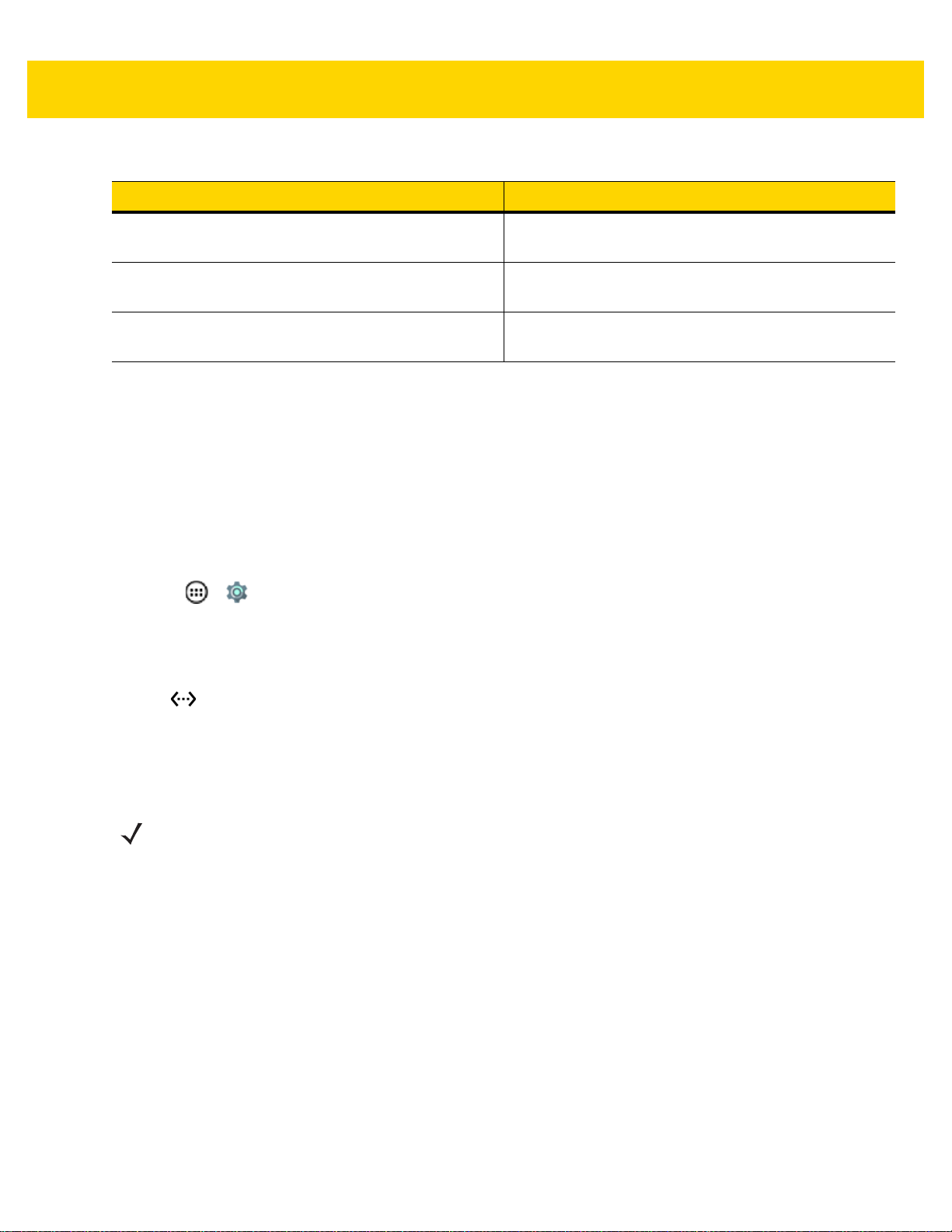
Accessories 2 - 31
Table 2-6 Spare Battery Charging LED Indicators (Continued)
LED Indication
Solid Red Charging complete and battery is at the end of useful
life.
Fast Blinking Red Error in charging; check placement of spare battery
and battery is at the end of useful life.
Off No spare battery in slot; spare battery not placed
correctly; cradle is not powered.
Charging Temperature
Charge batteries in temperatures from 0 °C to 40 °C (32 °F to 104 °F). The device or cradle always performs
battery charging in a safe and intelligent manner. At higher temperatures (e.g. approximately +37 °C (+98 °F)) the
device or cradle may for small periods of time alternately enable and disable battery charging to keep the battery at
acceptable temperatures. The device and cradle indicates when charging is disabled due to abnormal
temperatures via its LED.
Establishing Ethernet Connection
1. Touch > .
2. Touch Ethernet.
3. Insert the device into a slot.
4. Slide the Ethernet switch to the ON position.
The icon appears in the Status bar.
5. Touch Eth0 to view Ethernet connection details.
Installing the 4-Slot Battery Charger
NOTE The Battery Charger must be installed in the first slot only.
1. Remove power from the cradle.
Page 66
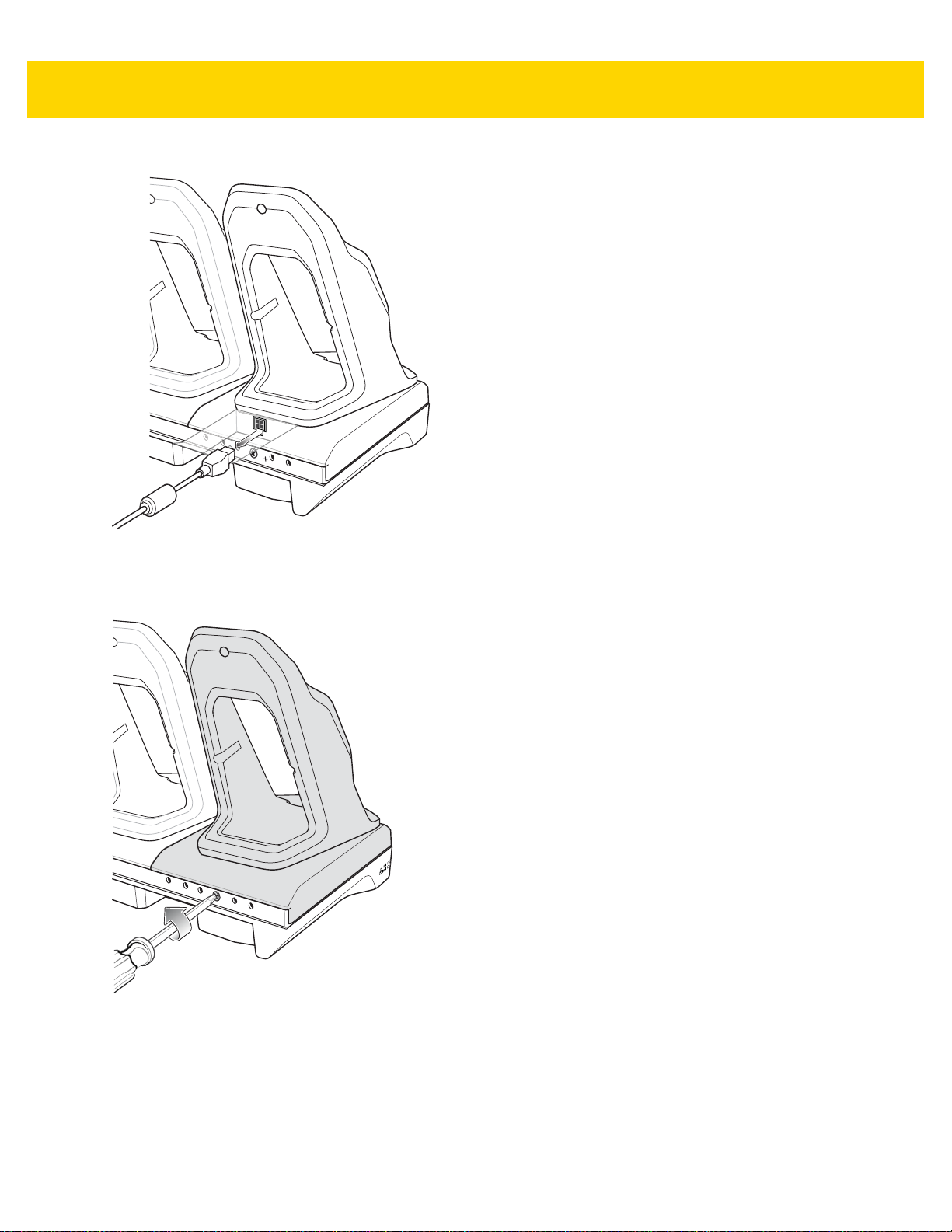
2 - 32 TC70x/TC75x Integrator Guide
Figure 2-34 Remove Power from Cradle
2. Using a Phillips screwdriver, remove the screw securing the cup to the cradle base.
Figure 2-35 Remove Screw
3. Slide the cup to the front of the cradle.
Page 67
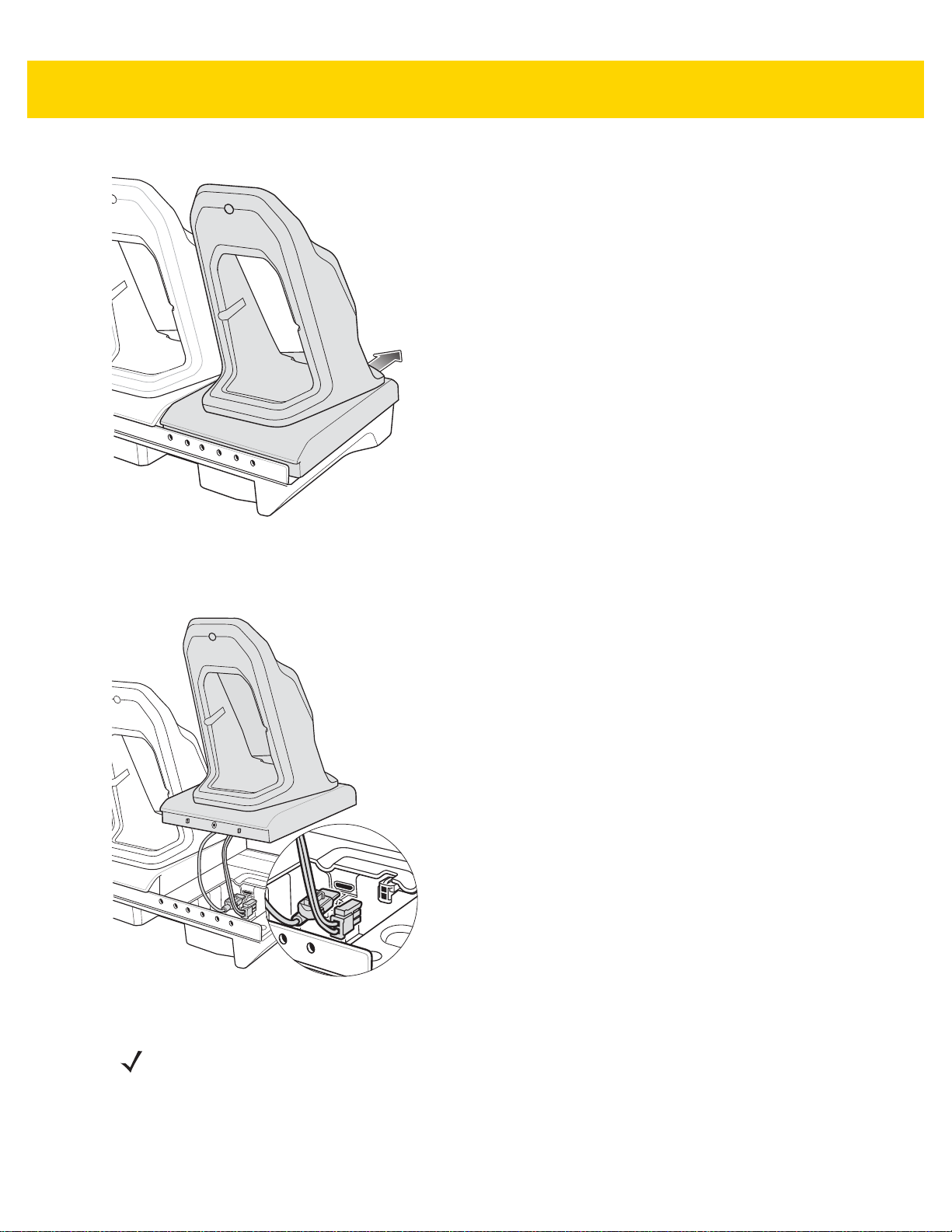
Figure 2-36 Remove Cup
Accessories 2 - 33
4. Carefully lift the cup up to expose the cup power cable.
5. Disconnect the cup power cable and USB cable.
Figure 2-37 Disconnect Cup Cables
NOTE Place power cable into adapter to avoid pinching cable.
6. Connect the Battery Adapter power cable to the connector on the cradle.
Page 68
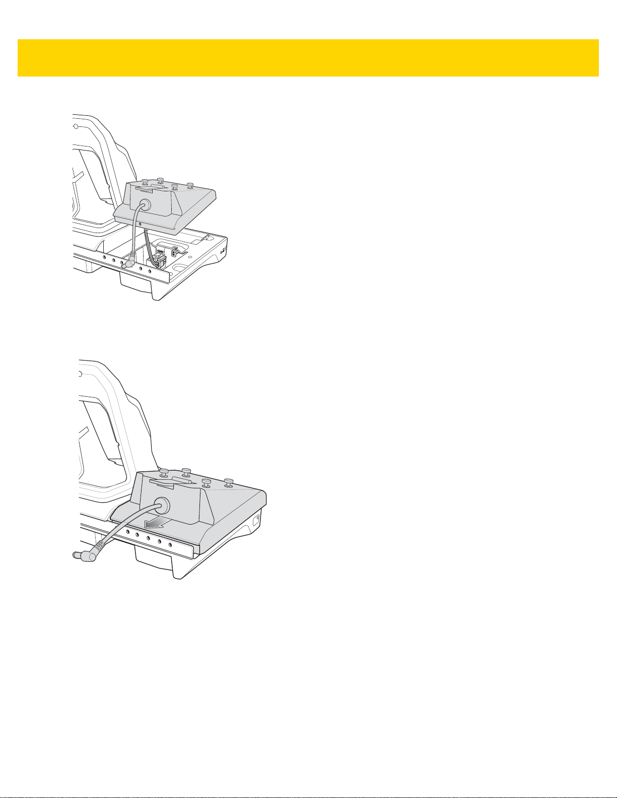
2 - 34 TC70x/TC75x Integrator Guide
Figure 2-38 Connect Adapter Power Cable
7. Place adapter onto cradle base and slide toward rear of cradle.
Figure 2-39 Install Adapter
8. Using a Phillips screwdriver, secure adapter to cradle base with screw.
Page 69
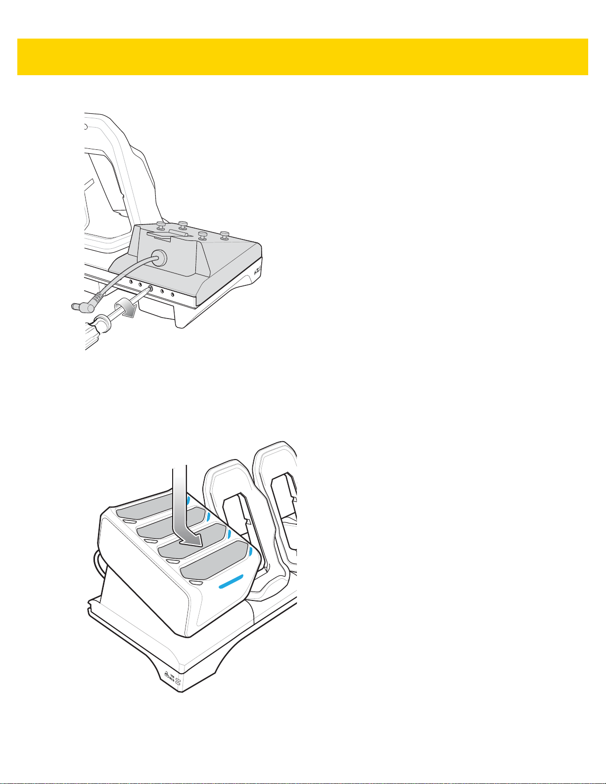
Accessories 2 - 35
Figure 2-40 Secure adapter to Cradle
9. Align mounting holes on the bottom of the 4-Slot Battery Charger with the stubs on the Battery Adapter.
Figure 2-41 Install 4-Slot Battery Charger
10. Slide the 4-Slot battery Charger down toward the front of the cradle.
Page 70
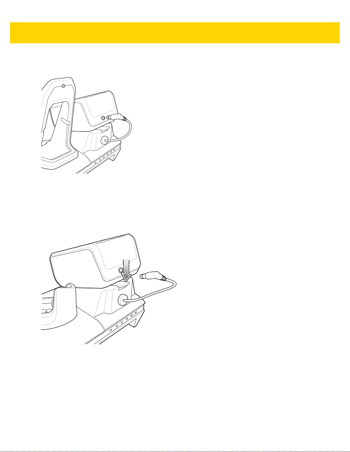
2 - 36 TC70x/TC75x Integrator Guide
11. Connect the output power plug into the power port on the 4-Slot Battery Charger.
Figure 2-42 Connect Adapter Power Cable
Removing the 4-Slot Battery Charger
1. Disconnect the output power plug from the 4-Slot Battery Charger.
2. At the back of the cup, press down on the release latch.
Figure 2-43 Press Release Latch
3. Slide the 4-Slot Battery Charger toward the front of the cradle.
4. Lift the 4-Slot off the cradle cup.
Page 71
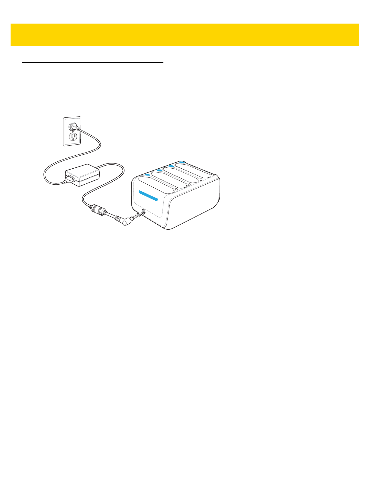
4-Slot Battery Charger
This section describes how to use the 4-Slot Battery Charger to charge up to four TC70x/TC75x batteries.
Setup
Accessories 2 - 37
Figure 2-44 Four Slot Battery Charger Power Setup
Charging Spare Batteries
1. Connect the charger to a power source.
2. Insert the battery into a battery charging well and gently press down on the battery to ensure proper contact.
Page 72
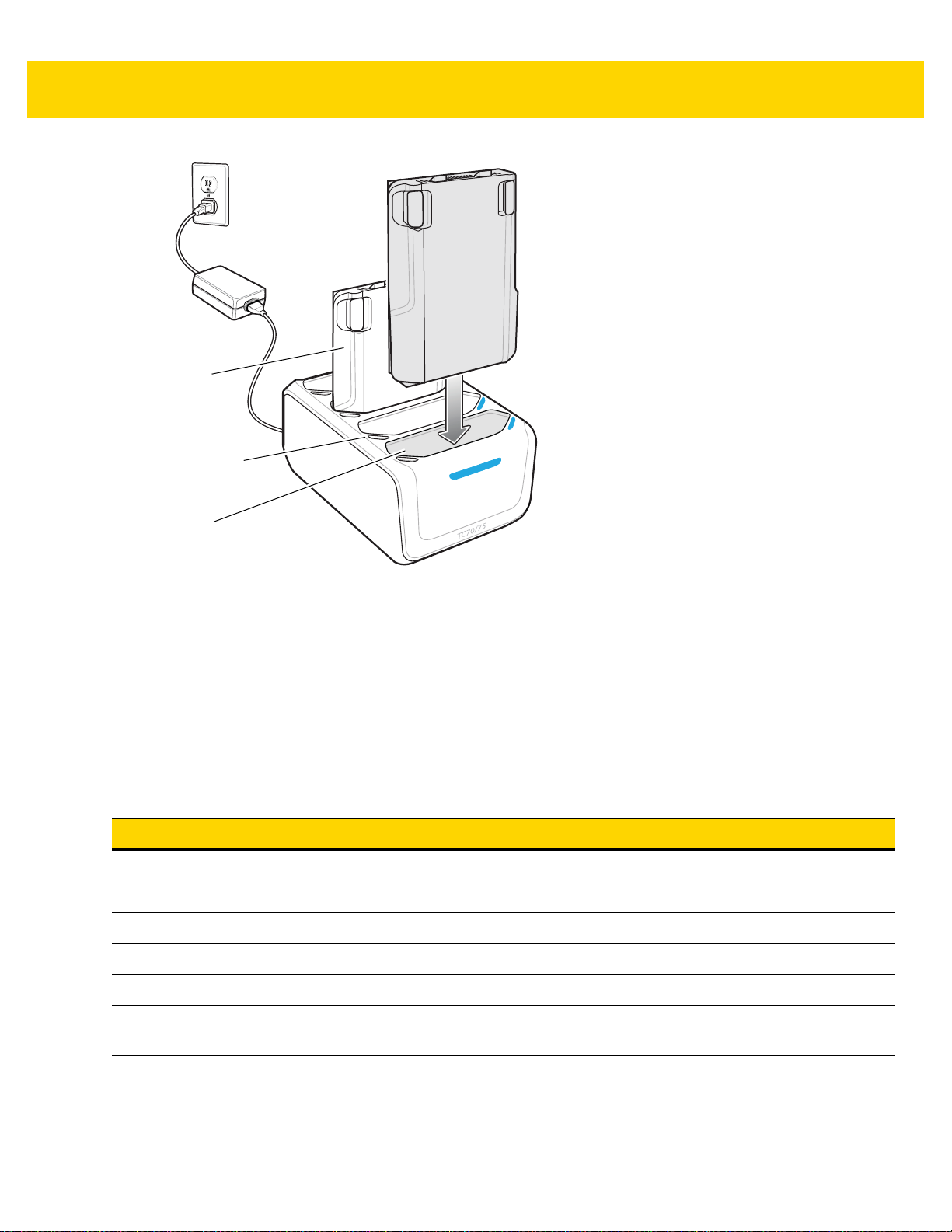
2 - 38 TC70x/TC75x Integrator Guide
Battery
Battery Charge LED
Battery Slot
Figure 2-45 Four Slot Battery Charger
Battery Charging
Spare Battery Charging
Each Battery Charging LED indicates the status of the battery charging in each slot. The t able below describ es the
Battery Charging LED status.
The 4,620 mAh battery fully charges in less than five hours at room temperature.
Table 2-7 Battery LED Charging Indicators
Slow Blinking Amber Spare battery is charging.
Solid Green Charging complete.
Fast Blinking Amber Error in charging; check placement of spare battery.
Slow Blinking Red Spare battery is charging and battery is at the end of useful life.
Solid Red Charging complete and battery is at the end of useful life.
Fast Blinking Red Error in charging; check placement of spare battery and batter y is at the
LED Indication
end of useful life.
Off No spare battery in slot; spare battery not placed correctly; cradle is not
powered.
Page 73

Accessories 2 - 39
Charging Temperature
Charge batteries in temperatures from 0 °C to 40 °C (32 °F to 104 °F). The battery charger always performs battery
charging in a safe and intelligent manner. At higher temperatures (e.g. approximately +37 °C (+98 °F)) the battery
charger may for small periods of time alternately enable and disable battery charging to keep the battery at
acceptable temperatures. The battery charger ind icates when charging is disabled due to abnormal temperatures
via its LED.
Page 74

2 - 40 TC70x/TC75x Integrator Guide
Trigger
Attachment Plate with
Tether
Latch
Release Button
Trigger Handle
The Trigger Handle adds a gun-style handle with a scanning trigger to the device. It incre ases comfort when using
the device in scan-intensive applications for extended periods of time.
Figure 2-46 Trigger Handle
Installing the Attachment Plate to Trigger Handle
To install the attachment plate to the Trigger Handle:
1. Insert the loop end of the tether into the slot on the bottom of the handle.
2. Feed the attachment plate throu g h th e loop.
Figure 2-47 Install Attachment Plate to Handle
3. Pull the attachment plate until the loop tightens on the tether.
Installing the Trigger Handle Plate
1. Press and hold the Power button until the menu appears.
2. Touch Power off.
3. Touch OK.
Page 75

Accessories 2 - 41
4. Press in the two battery latches.
5. Lift the battery from the device.
6. Remove the hand strap filler plate from the hand strap slot. Store the hand strap filler plate in a safe place for
future replacement.
Figure 2-48 Remove Hand Strap Plate
7. Insert the attachment plate into the hand strap slot.
Figure 2-49 Insert Trigger Handle Plate
8. Insert the battery, bottom first, into the battery compartment in the back of the device.
9. Rotate the top of the battery into the battery compartment.
10. Press the battery down into the battery compartment until the battery release latches snap into place.
Inserting the Device into the Trigger Handle
1. Align the back of the Trigger handle with the Trigger Mounting Plate.
Page 76

2 - 42 TC70x/TC75x Integrator Guide
Figure 2-50 Connect Device to Trigger Handle
2. Press the two release latches.
3. Rotate the device down and press down until it snaps into place.
Figure 2-51 Rotate Device onto Trigger Handle
Page 77

Removing the Device from the Trigger Handle
1. Press both Trigger Handle release latches.
Accessories 2 - 43
Figure 2-52 Press Release Latches
2. Rotate the device up and remove from the Trigger handle.
3. Rotate the device down and press down until it snaps into place.
Page 78

2 - 44 TC70x/TC75x Integrator Guide
Figure 2-53 Rotate Device onto Trigger Handle
Page 79

Hand Strap Replacement
CAUTION Close all running applications prior to replaci ng the hand strap.
1. Press and hold the Power button until the menu appears.
2. Touch Power Off.
3. Touch OK.
4. Remove the hand strap clip from the hand strap mounting slot.
Figure 2-54 Remove Hand Strap Clip
Accessories 2 - 45
5. Press the two battery latches in.
Figure 2-55 Press Battery Latches
6. Lift the battery from the TC70x/TC75x.
Page 80
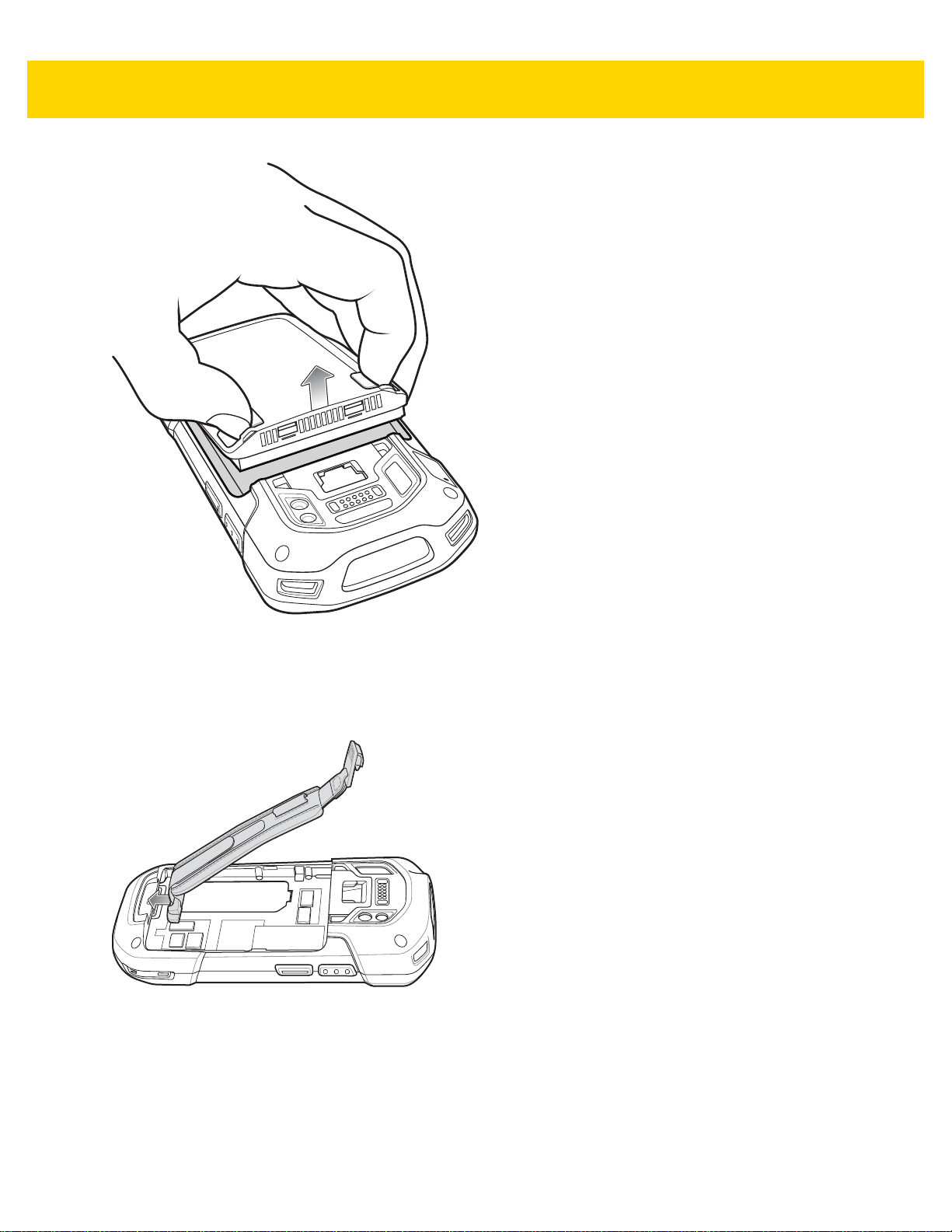
2 - 46 TC70x/TC75x Integrator Guide
Figure 2-56 Lift the Battery
7. Remove the battery.
8. Remove the hand strap plate from the hand strap slot.
9. Insert the replacement hand strap plate into the hand strap slot.
Figure 2-57 Insert Hand Strap
10. Insert the battery, bottom first, into the battery compartment.
Page 81
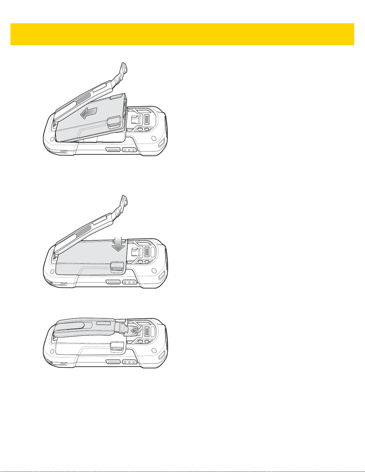
Accessories 2 - 47
Figure 2-58 Insert Bottom of Battery into Battery Compartment
11. Rotate the top of the battery into the battery compartment.
12. Press the battery down into the battery compartment until the battery release latches snap into place.
Figure 2-59 Press Down on Battery
13. Place hand strap clip into hand strap mounting slot and pull down until it snaps into place.
Figure 2-60 Secure Hand Strap Clip
Page 82

2 - 48 TC70x/TC75x Integrator Guide
Page 83

CHAPTER 3 USB COMMUNICATION
Introduction
This chapter provides information for transferring files between the device and a host computer.
Connecting to a Host Computer via USB
Connect the TC70x/TC75x to a host computer using the USB Charging cable to transfer files between the
TC70x/TC75x and the host compute r.
When connecting the TC70x/TC75x to a host computer, follow the host computer’s instructions for connecting and
disconnecting USB devices, to avoid damaging or corrupting files.
Transferring Files using Media Transfer Protocol
NOTE Use Media Transfer Protocol (MTP) to copy files between the TC70x/TC75x (internal memory or microSD
card) and the host computer.
1. Connect the USB Charge cable to the TC70x/TC75x and then to the host computer.
2. Pull down the Notification panel and touch USB for Charging.
Page 84
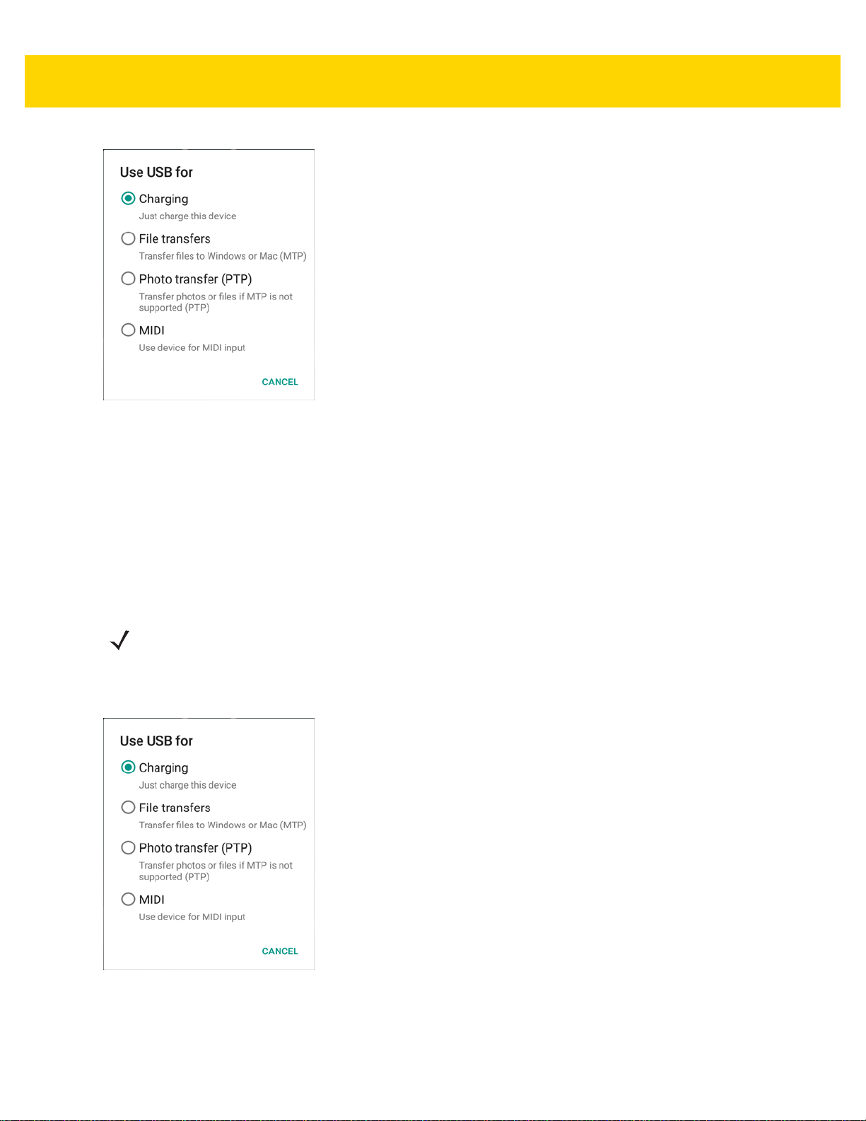
3 - 2 TC70x/TC75x Integrator Guide
Figure 3-1 Use USB Dialog Box
3. Touch File transfers.
4. On the host computer, open a file explorer application.
5. Locate the TC70x/TC75x as a portable device.
6. Open the SD card or the Internal storage folder.
7. Copy or delete files as required.
Transferring Files using Photo Transfer Protocol
NOTE Use Photo T ransfer Prot ocol (PTP) to copy photo s from either t he microSD ca rd or internal memory to the
host computer.
1. Connect the USB Charge cable to the TC70x/TC75x and then to the host computer.
2. Pull down the Notification panel and touch USB for Charging.
Figure 3-2 Use USB Dialog Box
3. Touch Photo transfer (PTP).
4. On the host computer, open a file explorer application.
Page 85

5. Open the SD card or the Internal storage folder.
6. Copy or delete photos as required.
Disconnect from the Host Computer
CAUTION Carefully follow the host computer’s instructions to unmount the microSD card and disconnect USB
devices correctly to avoid losing information.
1. On the host computer, unmount the device.
2. Remove the USB Charging cable from the device.
Getting Started 3 - 3
Page 86

3 - 4 TC70x/TC75x Integrator Guide
Page 87
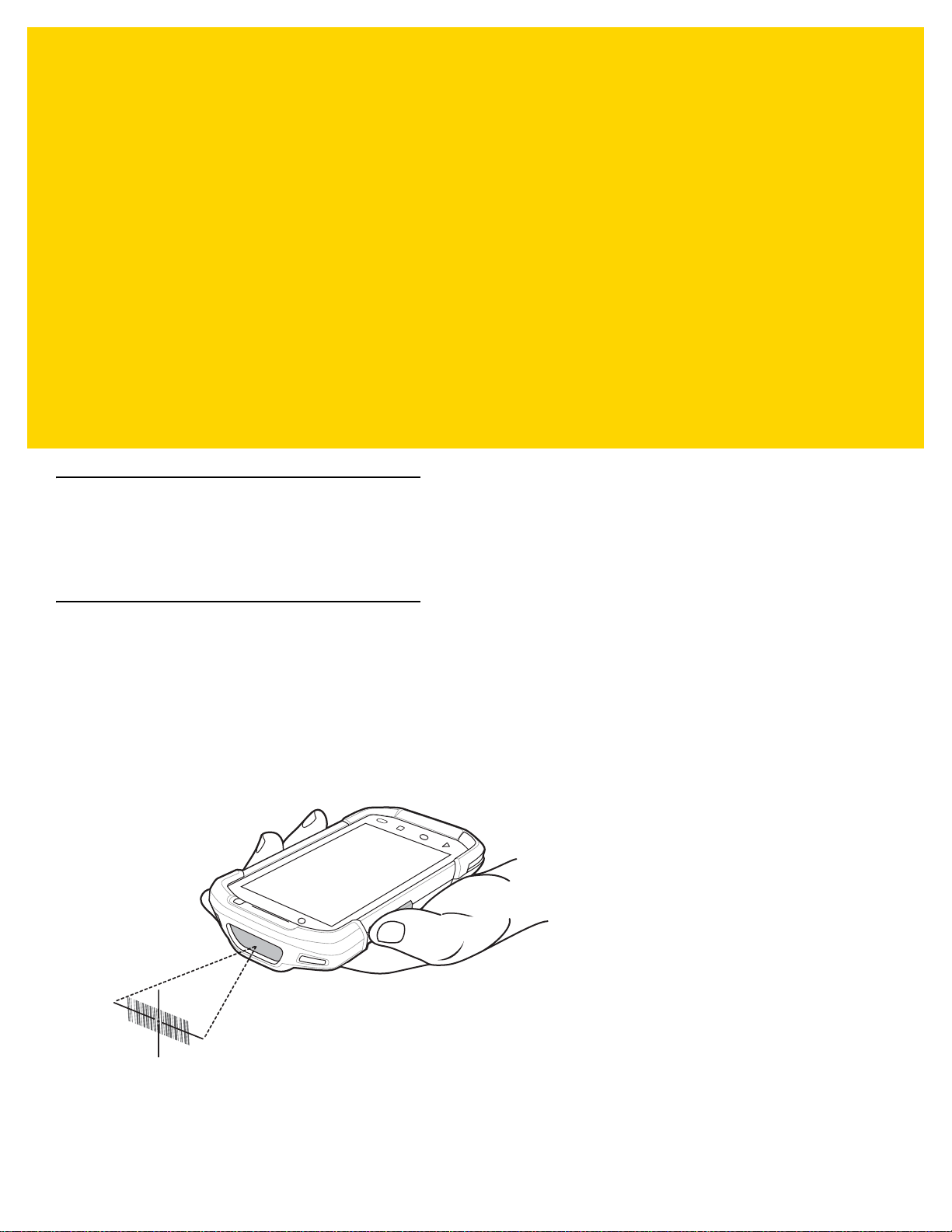
CHAPTER 4 DATAWEDGE
Introduction
This chapter applies to DataWedge on Android devices. DataWedge is an application that reads data, processes
the data and sends the data to an application.
Basic Scanning
To capture bar code data:
1. Ensure that an application is open on the TC70x/TC75x and a text field is in focus (text cursor in text field).
2. Aim the exit window at a bar code.
3. Press and hold the a Scan button. The red laser aiming patte rn turns on to assist in aiming. Ensur e that the bar
code is within the area formed by the aiming pattern. The Data Capture LED lights red to indicate that data
capture is in process.
Figure 4-1 TC70x/TC75x Data Capture
4. The Data Capture LED lights green, a beep sounds and theTC70x/TC75x vibrates, by default, to indicate the
bar code was decoded successfully. The captured data appears in the text field.
Page 88

4 - 2 TC70x/TC75x Integrator Guide
Profiles
DataWedge is based on profiles and plug-ins. A profile contains information on how DataWedge should behave
with different applications.
Profile information consists of:
• Associated application
• data capture plus configurations
• Input plug-in configurations
• Output plug-in configurations
• Process plug-in configurations.
Using profiles, each application can have a specific DataWedge configuration. Fo r ex amp le, ea ch user ap plication
can have a profile which outputs scanned data in the required format when that application comes to the
foreground. DataWedge can be configured to process the same set of captured data differently based on the
requirements of each application.
DataWedge includes the following pre-configured profiles which support specific built-in applications:
•Profile0 - created automatically the first time DataWedge runs. Generic profile used when there are no user
• Launcher - enables scanning when the Launcher is in foreground. Note: to save battery power, disable this
•DWDemo - provides support for the DWDemo application.
Some Zebra applications are capable of capturing data by scanning. DataWedge is pre-loaded with private and
hidden profiles for this purpose. There is no option to modify these private profiles.
Profile0
Profile0 can be edited but cannot be associated with an application. That is, DataWedge allows manipulation of
plug-in settings for Profile0 but it does not allow assignment of a foreground application. This configuration allows
DataWedge to send output data to any foreground application ot her than applications associated with user-defined
profiles when Profile0 is enabled.
Profile0 can be disabled to allow DataWedge to only send output data to those applications which are associated
in user-defined profiles. For example, create a profile associating a specific application, disable Profile0 and then
scan. DataWedge only sends data to the application specified in the user-created profile. This adds additional
security to DataWedge enabling the sending of data only to specified applications.
Plug-ins
created profiles associated with an application.
profile when not required.
A plug-in is a software module utilized in DataWedge to extend its functionality to encompass technologies such as
bar code scanning. The plug-ins can be categorized into three types based on their operations:
• Input Plug-ins
• Output Plug-ins
• Process Plug-ins.
Page 89

DataWedge 4 - 3
Input Plug-ins
An Input Plug-in supports an input device, such as a bar code scanner contained in, or attached to the device.
DataWedge contains base plug-ins for these input devices.
• Bar Code Scanner Input Plug-in – The Bar Code Scanner Inpu t Plug-in is responsible for reading data from
the integrated bar code scanner and supports diff erent types of bar code reade rs including laser, imager and
internal camera. Raw data read from the bar code scanner can be processed or formatted using Process
Plug-ins as required. DataWedge has built-in feedback functionality for the bar code scanner to issue user
alerts. The feedback settings can be configured according to user requirement.
Process Plug-ins
Process Plug-ins are used in DataWedge to manipulate the received data according to the requirement, befo r e
sending to the foreground application via the Output Plug-in.
• Advanced Data Formatting Process Plug-in– The Adva nced Data Formatting Plug-in allows DataWedge
to apply rules (actions to be performed based on defined criteria) to the data received via an input plug-in
before passing it to an Output Plug-in.
• Basic Data Formatting Process Plug-in– The Basic Data Formatting Plug-in allows DataWedge to add a
prefix and/or a suffix to the captured data before passing it to an Output Plug-in.
Output Plug-ins
Output Plug-ins are responsible for sending the data from Input Plug-ins to a foreground application on the device.
• Keystroke Output Plug-in – The Keystroke Output Plug-in collects and sends data received from the Input
Plug-in to the foreground applications by emulating keystrokes.
• Intent Output Plug-in – The Intent Ou tput Plug-in collects and sends data received from the Input Plug-ins
to foreground applications using the Android Intent mechanism.
• IP Output Plug-in – The IP Output Plug-in collects and sends d ata received from the Inp ut Plug-ins to a host
computer via a network connection. Captured data can be sent over an IP network to a specified IP address
and port using either TCP or UDP transport protocols.
Page 90

4 - 4 TC70x/TC75x Integrator Guide
Profiles Screen
To launch DataWedge, touch > . By default, three profiles appear:
•Profile0
• Launcher
•DWDemo.
Profile0 is the default profile and is used when no other profile can be applied.
Figure 4-2 DataWedge Profiles Screen
Profile names are color coded. Enabled profiles are white and disabled profiles are gray.
To configure a profile touch the profile name.
Profile Context Menu
Touch and hold a profile to open a context menu that allows additional actions to be performed on the selected
profile.
Page 91
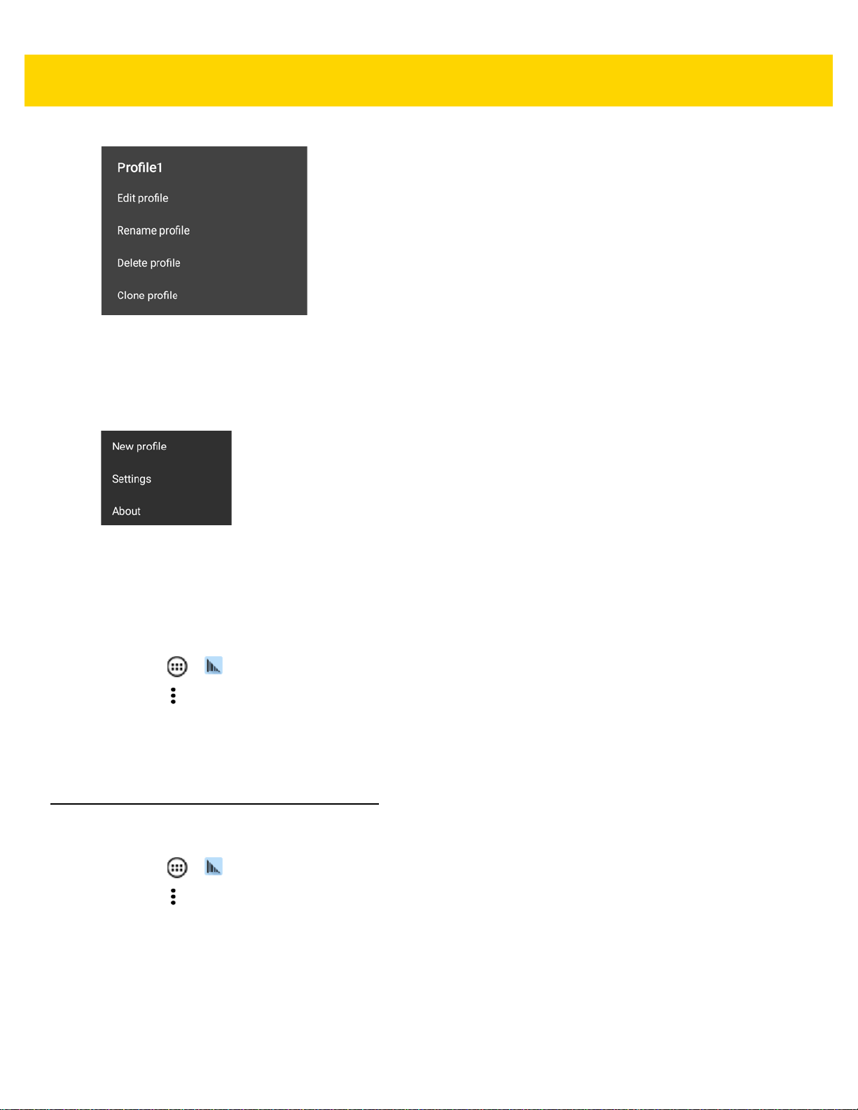
DataWedge 4 - 5
Figure 4-3 Profile Context Menu
The profile context menu allows the profile to be edited (same as just tapping on a profile), renamed or deleted.
Options Menu
Figure 4-4 DataWedge Options Menu
The menu provides options to create a new profiles, access to general DataWedge settings and DataWedge
version information.
Disabling DataWedge
1. Touch > .
2. Touch .
3. Touch Settings.
4. Touch DataWedge enabled.
The blue check disappears from the checkbox indicating that DataWedge is disabled.
Creating a New Profile
5. Touch > .
6. Touch .
7. Touch New profile.
8. In the New profile dialog box, enter a name for the new profile. It is recommended that profile names be
unique and made up of only alpha-numeric characters (A-Z, a-z, 0-9) .
Page 92

4 - 6 TC70x/TC75x Integrator Guide
Figure 4-5 New Profile Name Dialog Box
9. Touch OK.5
The new profile name appears in the DataWedge profile screen.
Profile Configuration
To configure the Profile0 or a user-created profile, touch the profile name.
Figure 4-6 Profile Configuration Screen
The configuration screen lists the following sections:
• Profile enabled
• Applications
• Data Capture panel (DCP)
• Barcode Input
Page 93

DataWedge 4 - 7
• Keystroke output
• Intent Output
• IP Output.
Associating Applications
Use Applications option to associate applications with this profile. User created profiles should be associated with
one or more applications and its activities.
1. Touch Associated apps. A list of applications/activities associated with the profile displays. Initially the list
does not contain any applications/activities.
Figure 4-7 Associated Apps Screen
2. Touch .
3. Touch New app/activity.
Page 94

4 - 8 TC70x/TC75x Integrator Guide
Figure 4-8 Select Application Menu
4. In the Select application screen, select the desired application from the list.
5. In the Select activity menu, selecting the activity adds that application/activity combination to the associated
application list for that profile. Selecting * as the activity results in all activities within that application being
associated to the profile. During opera tion , Da ta Wedge tries to match the specific application/activity
combinations with the foreground application/activity before trying to match the general application/*
combinations.
6. Touch .
Page 95

DataWedge 4 - 9
Figure 4-9 Selected Application/Activity
Data Capture Plus
Data Capture Plus (DCP) is a DataWedge feature that enables the user to initiate data capture by touching a
designated part of the screen. A variable screen overlay acts like a scan button.
Page 96
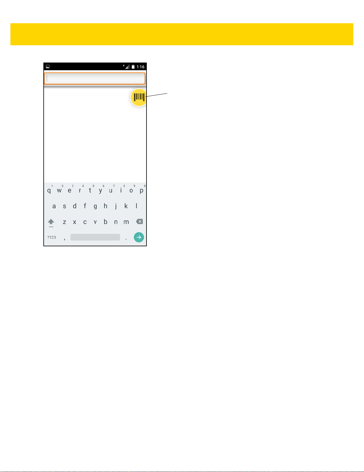
4 - 10 TC70x/TC75x Integrator Guide
DCP Button
Figure 4-10 Minimized Data Capture Panel
The DataWedge profile configuration screen allows the user to configure how the DCP appears on the screen once
the particular profile is enabled. The DCP is hidden by default. Enabling DCP option displays seven additional
configuration parameters.
Page 97
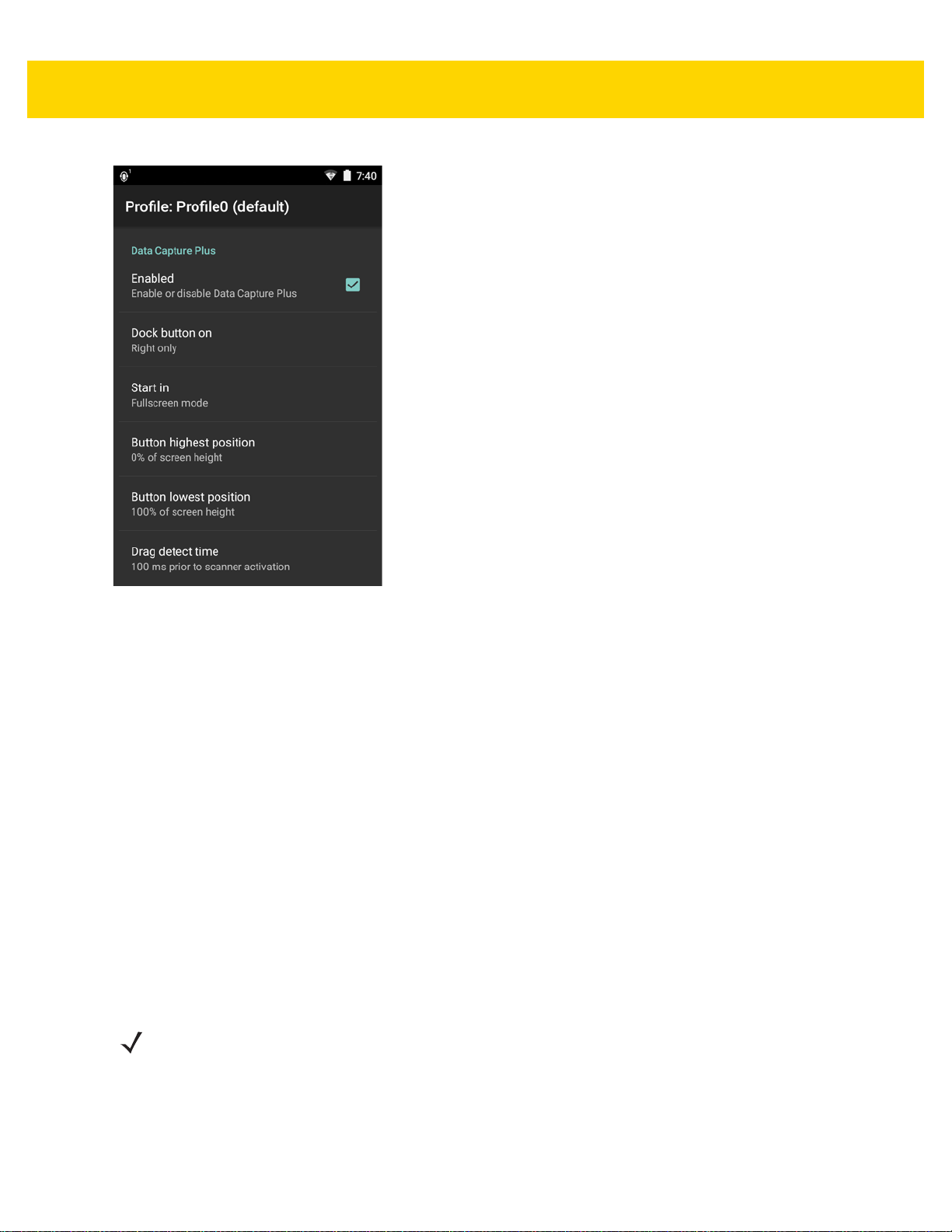
DataWedge 4 - 11
Figure 4-11 Data Capture Panel Settings
• Enable - Select to enable Data Capture Plus (default - disabled).
• Dock button on - Select position of the button.
• Left or right - Allo ws user to place the button on either the right or left edge of the screen.
• Left only - Places the button on left edge of the screen.
• Right only - Places the button on the right edge of the screen.
•Start in - Select the initial DCP state.
• Fullscreen mode - DCP covers the whole screen.
• Button mode - DCP displays as a circular button on the screen and can be switched to fullscreen mode.
• Button only mode - DCP displays a s a circular button on the screen and cannot be switched to fu llscreen
mode.
• Button highest position - Select the top of the range the user is allowed to move the DCP, given as a
percent of the screen height (default - 0).
• Button lowest position - Select the bottom of the range the user is allowed to move the DCP, given as a
percent of the screen height (default - 100).
• Drag detect time - Select the time in milliseconds that the scanner waits before activating scanner. This
allows the user to drag the button without initiating scanner (default - 100 ms, maximum 1000 ms).
NOTE The DCP does not appear if the scanner is disabled in the profile even though the Enabled option is set.
In Button mode, the user can place DCP in full screen mode by dragging the button over Fullscreen mode. The
overlay covers the screen.
Page 98
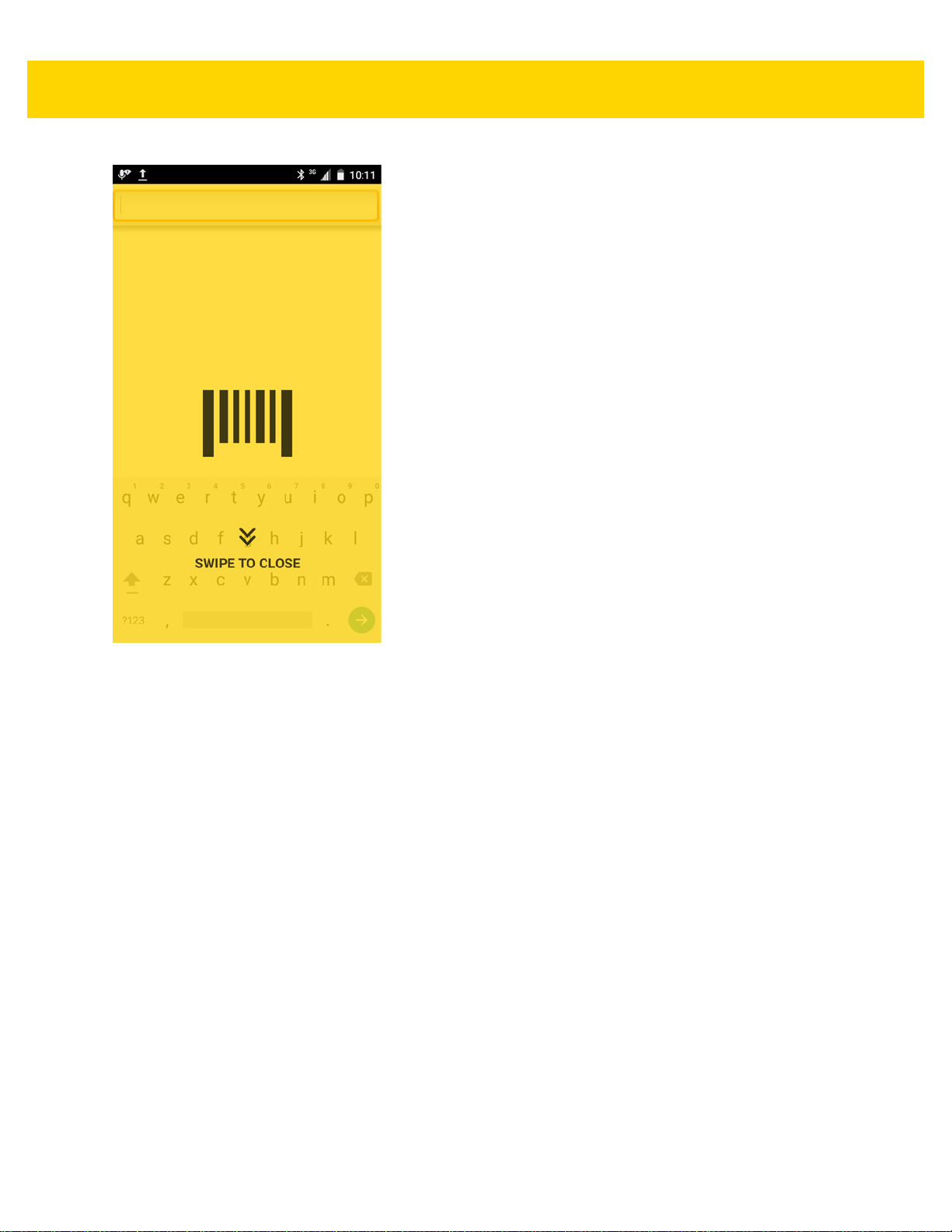
4 - 12 TC70x/TC75x Integrator Guide
Figure 4-12 Maximized DCP
Swipe down to return to button mode.
Bar Code Input
Use the Bar Code Input options to configure the Bar Code Scanner Input Plug-in for the profile.
Enabled
Enables or disables this plug-in. A check in the checkbox indicates that the plug-in is enabled.
Scanner Selection
Configures which scanning device to use for bar code data capture when the profile is active.
•Auto - The software automatically determines the best scanning device.
• 2D Barcode Imager - Scanning is performed using the 2D Imager.
• Bluetooth Scanner - Scanning is performed using the option Bluetooth scanner.
Decoders
Configures which bar code decoders are en ab le d or disa ble d. For bes t perfo rm a nc e dis ab l e all un ne cessary
decoders.
Page 99

DataWedge 4 - 13
Touch Decoders. The Barcode input screen appears. A check in the checkbox indicates that the decoder is
enabled. By default the most commonly used decoders are enabled (sho wn below with an asterisk). The supported
decoders are:
NOTE DataWedge supports the decoders listed below but not all are validated on this device.
Table 4-1 Supported Decoders
Decoders Imager RS507 RS6000
Australian Postal Disabled Disabled Disabled
Aztec Enabled Enabled E nabled
Canadian Postal Disabled Not supported Disabled
Chinese 2 of 5 Disabled Disabled Disabled
Codabar Enabled Enabled Enabled
Code 11 Disabled Disabled Disabled
Code 128 Enabled Enabled Enabled
Code 39 Enabled Enabled Enabled
Code 93 Disabled Disabled Disabled
Composite AB Disabled Disabled Disabled
Composite C Disabled Disabled Disabled
Discrete 2 of 5 Disabled Disabled Disabled
Datamatrix Enabled Enabled Enabled
Dutch Postal Disabled Disabled Disabled
EAN-13 Enabled Enabled Enabled
EAN-8 Enabled Enabled Enabled
GS1 DataBar Enabled Enabled Enabled
GS1 DataBar Expanded Enabled Enabled Enabled
GS1 DataBar Limited Disabled Disabled Disabled
HAN XIN Disabled Not supported Disabled
Interleaved 2 of 5 Disabled Disabled Disabled
Japanese Postal Disabled Disabled Disabled
Korean 3 of 5 Disabled Disabled Disabled
MAIL MARK Enabled Not supported Enabled
Matrix 2 of 5 Disabled Disabled Disabled
Page 100

4 - 14 TC70x/TC75x Integrator Guide
Table 4-1 Supported Decoders (Continued )
Decoders Imager RS507 RS6000
Maxicode Enabled Enabled Enabled
MicroPDF Disabled Disabled Disabled
MicroQR Disabled Disabled Disabled
MSI Disabled Disabled Disabled
PDF417 Enabled Enabled Enabled
QR Code Enabled Enabled Enabled
Decoder Signature Disabled Disabled Disabled
TLC 39 Disabled Disabled Disabled
Trioptic 39 Disabled Disabled Disabled
UK Postal Disabled Disabled Disabled
UPC-A Enabled Enabled Enabled
UPC-E0 Enabled Enabled Enabled
UPC-E1 Disabled Disabled Disabled
US4state Disabled Disabled Disabled
US4state FICS Disabled Disabled Disabled
US Planet Disabled Disabled Disabled
US Postnet Disabled Disabled Disabled
Touch to return to the previou s screen.
Decoder Params
Use Decode Params to configure individual decoder parameters.
Codabar
• CLSI Editing - Enable this parameter to strip the start and stop characters and insert a space after the
first, fifth, and tenth characters of a 14-character Codabar symbol. Enable this feature if the host system
requires this data format (default - disabled).
• Length1 - Use to set decode lengths (default - 6). See Decode Lengths on page 4-20 for more
information.
• Length2 - Use to set decode lengths (default - 55). See Decode Lengths on page 4-20 for more
information.
• NOTIS Editing - Enable this parameter to strip the start and stop characters from a decoded Codabar
symbol. Enable this feature if the host system requires this data format (default - disabled).
• Redundancy - Sets the reader to read the bar code twice befo re accepting data. A check in the ch eckbox
indicates that redundancy is enabled (default - enabled).
 Loading...