


SB1
SMART BADGE
USER GUIDE


SB1 SMART BADGE
USER GUIDE
72E-164711-04
Rev. A
May 2019

ii SB1 User Guide
No part of this publication may be reproduced or used in any form, or by any electrical or mechanical means,
without permission in writing from Zebra. This includes electronic or mechanical means, such as photocopying,
recording, or information storage and retrieval systems. The material in this manual is subject to change
without notice.
The software is provided strictly on an “as is” basis. All software, including firmware, furnished to the user is on
a licensed basis. Zebra grants to the user a non-transferable and non-exclusive license to use each software
and firmware program delivered hereunder (licensed program). Except as noted below, such license may not
be assigned, sublicensed, or otherwise transferred by the user without prior written consent of Zebra. No right
to copy a licensed program in whole or in part is granted, except as permitted under copyright law. The user
shall not modify, merge, or incorporate any form or portion of a licensed program with other program material,
create a derivative work from a licensed program, or use a licensed program in a network without written
permission from Zebra. The user agrees to maintain Zebra’s copyright notice on the licensed programs
delivered hereunder, and to include the same on any authorized copies it makes, in whole or in part. The user
agrees not to decompile, disassemble, decode, or reverse engineer any licensed program delivered to the user
or any portion thereof.
Zebra reserves the right to make changes to any software or product to improve reliability, function, or design.
Zebra does not assume any product liability arising out of, or in connection with, the application or use of any
product, circuit, or application described herein.
No license is granted, either expressly or by implication, estoppel, or otherwise under any Zebra, intellectual
property rights. An implied license only exists for equipment, circuits, and subsystems contained in Zebra
products.

Revision History
Changes to the original guide are listed below:
Change Date Description
Rev. 060412 06/04/12 Draft.
Rev. 092612 09/26/12 Draft 2
Rev. A 03/2015 Zebra Rebranding
-04 Rev. A 5/2019 Update cleaning procedures on page 5-2.
iii

iv SB1 User Guide

TABLE OF CONTENTS
Revision History .............................................................................................................................. iii
About This Guide
Introduction ..................................................................................................................................... ix
Documentation Set ................................................................................................................... ix
Configurations................................................................................................................................. ix
Software Versions..................................................................................................................... ix
Chapter Descriptions ...................................................................................................................... x
Notational Conventions................................................................................................................... x
Related Documents and Software .................................................................................................. xi
Service Information ......................................................................................................................... xi
Chapter 1: Getting Started
Introduction .................................................................................................................................... 1-1
Unpacking the SB1 ........................................................................................................................ 1-1
Features ......................................................................................................................................... 1-2
Charging the SB1 ........................................................................................................................... 1-3
Resetting the SB1 .......................................................................................................................... 1-5
Powering Off the SB1 .................................................................................................................... 1-5
Chapter 2: Operation
Wearing the SB1 ............................................................................................................................ 2-1
Lanyard .................................................................................................................................... 2-1
Holster ...................................................................................................................................... 2-2
Armband .................................................................................................................................. 2-3
Entering Data ................................................................................................................................. 2-3
Using a Headset ............................................................................................................................ 2-4
Using the Speaker Adapter ............................................................................................................ 2-6
Home Screen ................................................................................................................................. 2-7
Notifications ............................................................................................................................. 2-8
Locking the SB1 ....................................................................................................................... 2-9
Setting User Profile .................................................................................................................. 2-9

vi SB1 User Guide
Enter Name and Title ......................................................................................................... 2-10
Log Out .............................................................................................................................. 2-11
Switch Device .................................................................................................................... 2-11
Applications .............................................................................................................................. 2-11
Settings .................................................................................................................................... 2-12
Adjusting the Volume ......................................................................................................... 2-13
PTT Express Settings ........................................................................................................ 2-13
More Setting ............................................................................................................................. 2-13
Screen Calibration ............................................................................................................. 2-13
Beeper Settings ................................................................................................................. 2-14
Software Versions .............................................................................................................. 2-14
Advanced Setting ............................................................................................................... 2-14
PTT Express Voice Client .............................................................................................................. 2-15
PTT Audible Indicators ............................................................................................................. 2-15
PTT Express Voice Client Configuration .................................................................................. 2-16
Enable Voice Client Communication .................................................................................. 2-16
Select a Talk Group ........................................................................................................... 2-16
Disable PTT Express Voice Client Communication ........................................................... 2-17
PTT Communication ................................................................................................................ 2-17
Group Broadcast (One to Many) ........................................................................................ 2-17
Response to a Group Broadcast ........................................................................................ 2-18
Private Response (One to One) ......................................................................................... 2-18
Chapter 3: Data Capture
Introduction .................................................................................................................................... 3-1
Scanning Considerations ............................................................................................................... 3-1
Bar Code Reading ......................................................................................................................... 3-2
Chapter 4: Accessories
Introduction .................................................................................................................................... 4-1
Single Slot Charging Cradle .......................................................................................................... 4-2
Ten Slot Charge Only Cradle ......................................................................................................... 4-4
Audio Adapter ................................................................................................................................ 4-6
Speaker Adapter ............................................................................................................................ 4-8
Holster ........................................................................................................................................... 4-9
Armband ........................................................................................................................................ 4-11
Lanyard .......................................................................................................................................... 4-13
Chapter 5: Maintenance & Troubleshooting
Introduction .................................................................................................................................... 5-1
Maintaining the SB1 ...........................................
Battery Safety Guidelines .............................................................................................................. 5-1
Cleaning ......................................................................................................................................... 5-2
Approved Cleanser Active Ingredients ..................................................................................... 5-2
Harmful Ingredients .................................................................................................................. 5-2
Cleaning Instructions ............................................................................................................... 5-3
Special Cleaning Notes ............................................................................................................ 5-3
Materials Required ................................................................................................................... 5-3
............................................................................ 5-1

Table of Contents vii
Cleaning the SB1 ..................................................................................................................... 5-3
Housing .............................................................................................................................. 5-3
Display ............................................................................................................................... 5-3
Reader Exit Window ........................................................................................................... 5-3
Contacts ............................................................................................................................. 5-3
Cleaning Cradle Connectors .................................................................................................... 5-4
Cleaning Frequency ................................................................................................................. 5-4
Troubleshooting ............................................................................................................................. 5-5
SB1 .......................................................................................................................................... 5-5
Single Slot Charging Cradle ..................................................................................................... 5-6
Ten Slot Charge Only Cradle ................................................................................................... 5-6
Audio Adapter .......................................................................................................................... 5-7
Speaker Adapter ...................................................................................................................... 5-7
Appendix A: Sample Applications
Sales Demos .................................................................................................................................. A-1
Price Check Scenario .............................................................................................................. A-2
Fill Delivery Scenario ............................................................................................................... A-3
Unload Truck Scenario ............................................................................................................ A-4
Collect Carts Scenario ............................................................................................................. A-5
Reset Sales Demo ................................................................................................................... A-6
Exit Sales Demo ...................................................................................................................... A-6
Price Check .................................................................................................................................... A-7
FTP Client ...................................................................................................................................... A-9
Required .................................................................................................................................. A-10
Setup ........................................................................................................................................ A-10
Exit Application ........................................................................................................................ A-10
Appendix B: Specifications
SB1 Technical Specifications ......................................................................................................... B-1
Glossary
Index

viii SB1 User Guide

ABOUT THIS GUIDE
Introduction
This guide provides information about using the SB1 smart badge and accessories.
NOTE Screens and windows pictured in this guide are samples and may differ from actual screens.
Documentation Set
The documentation set for the SB1 is divided into guides that provide information for specific user needs.
•
SB1 Regulatory Guide - provides all regulatory and safety information.
•
SB1 User Guide - describes how to use the SB1.
•
SB1 Integrator Guide - describes how to set up and configure the SB1 and accessories.
•
SB1 Programmer’s Guide - Provides information for developing Rho-Elements based applications.
Configurations
This guide covers the following configurations:
Configuration Radios Display Memory Data Capture
SB1 WLAN: 802.11 b/g/n E Ink® touch
Software Versions
This guide covers various software configurations and references are made to software versions. To view the
software versions:
1. Press the Home button.
screen
128 MB RAM/
128 MB Flash
Bar code reader

x SB1 User Guide
2. Touch . The Settings screen appears.
3. Touch . The More Settings screen appears.
4. Touch Software Version. The Software Version screen lists the operating system (OS), RhoElements,
application folder and SB1 Shell version numbers.
Chapter Descriptions
Topics covered in this guide are as follows:
•
Chapter 1, Getting Started, describes the SB1’s physical characteristics, how to charge the SB1 and start
the SB1 for the first time.
•
Chapter 2, Operation, provides basic instructions for using the SB1 and navigating the SB1 Shell.
•
Chapter 3, Data Capture provides instructions for using the SB1 to capture data using the bar code
reader.
•
Chapter 4, Accessories, describes the accessories available for the SB1 and how to use the accessories
with the SB1.
•
Chapter 5, Maintenance & Troubleshooting, includes instructions on cleaning and storing and provides
troubleshooting solutions for potential problems during SB1 oper
•
Appendix A, Sample Applications provides information on default sample applications installed on the
SB1.
•
Appendix B, Specifications, includes a table listing the technical specifications for the SB1.
Notational Conventions
The following conventions are used in this document:
•
The term “SB1” refers to the Zebra SB1 smart badge.
•
Italics are used to highlight the following:
apters and sections in this and related documents
• Ch
• Dialo
• Dr
• Che
• Icons on a
•
Bold text is used to highlight the following:
• Key names on a keypad
• Button
g box, window and screen names
op-down list and list box names
ck box and radio button names
screen.
names on a screen.
ation.
•
Bullets (•) indicate:
ion items
• Act
• Lis
ts of alternatives
• L
ists of required steps that are not necessarily sequential.
•
Sequential lists (e.g., those that describe step-by-step procedures) appear as numbered lists.

Related Documents and Software
Manufacturing Label Location
The following items provide more information about the SB1.
•
SB1 Regulatory Guide, p/n 72-162415-xx
•
SB1 Integrator Guide, p/n 72E-164712-xx
•
SB1 Programmer’s Guide, p/n 72E-170991-xx
About This Guide xi
For the latest version of this gu
Service Information
If you have a problem with your equipment, contact Zebra Global Customer Support for your region. Contact
information is available at:
When contacting Zebra Global Custome
•
Serial number of the unit
•
Model number or product name
•
Software type and version number (on SB1, see Software Versions on page 1-ix)
Zebra responds to calls by email, te
If your problem cannot be solved by Ze
for servicing and will be given specific directions. Zebra is not responsible for any damages incurred during
shipment if the approved shipping container is not used. Shipping the units improperly can possibly void the
warranty.
If you purchased your product from a Zebra business partner, con
ide and all guides, go to: http://www.zebra.com/support
http://www.zebra.com/support.
r Support, please have the following information available:
lephone or fax within the time limits set forth in support agreements.
bra Global Customer Support, you may need to return your equipment
tact that business partner for support.

xii SB1 User Guide

CHAPTER 1 GETTING STARTED
Introduction
The SB1 is a brand new category of mobile device that employers can give to every retail associate. This truly
smart badge is full of the features every associate needs to deliver the best customer experience, with the
connectivity needed to keep them productive, every minute of every day. The badge each associate wears can
allow associates to: access a personalized task list; accept tasks and acknowledge completion; scan a bar
code to check price and inventory; and connect via push-to-talk (PTT) with other workers carrying practically
any other PTT-enabled mobile device in use in the store. The result is a powerful always-connected workforce
that can always access the people and information they need to maximize productivity and exceed customers’
expectations on every visit.
This chapter describes the SB1 physical characteristics, how to charge the SB1.
Unpacking the SB1
Carefully remove all protective material from around the SB1 and save the shipping container for later storage
and shipping. Verify that the equipment listed below is included:
•
SB1 (single unit or multi-unit)
•
Regulatory Guide.
Inspect the equipment for damage. If any equipment is missing or damaged, contact the Zebra Global
Customer Support immediately. See
Service Information on page xi for contact information.

1 - 2 SB1 User Guide
Home Button*
E Ink
®
Display
Scan Button
Lanyard Slot
Bar Code Reader
LED
Adapter Mounting Points
I/O Contacts
Charging
Contacts
* The Home button can be programmed to add a pause button function. See the SB1 Programmer’s Guide.
Features
The features of the SB1 are shown in Figure 1-1.
Figure 1-1
SB1 smart badge

Charging the SB1
LED
Scan Button
CAUTION Follow the guidelines for battery safety described in Battery Safety Guidelines on page 5-1.
When the SB1 is off it displays the Regulatory Label information screen.
Getting Started 1 - 3
The SB1 must be charged within the 0 °C to +35 °C (32 °F to 95 °F) ambient temperature range.
Figure 1-2
Use the Single Slot Charging cradle
Out of the Box Screen
or Ten Slot Charge Only cradle to charge the SB1. To charge the SB1,
slide it into the cradle slot with the Scan button facing up.
Figure 1-3
Single Slot Charging Cradle
NOTE If the battery is at a very low level due to the SB1 being left out overnight or stored for long periods, the
SB1 might not power up immediately when placed in a cradle, although the LED will blink. When the SB1
is placed in the charging cradle, the SB1 boots normally after a few minutes.
When the SB1 powers up a beep sounds and the Calibration screen displays

1 - 4 SB1 User Guide
Figure 1-4
Leave the SB1 in the cradle until it is ful
Calibration Screen
ly charged. The LED indicates the SB1 battery charging status. The
battery fully charges in approximately four hours. See Table 1-1 on page 1-4 for charging status indications.
When the LED lights green remove the SB1 from the cradle.
Carefully press and briefly hold finger tip on the center of the Calibration
screen target. Repeat the procedure
as the target moves and stops at different locations on the screen. After the calibration settings are input, tap
the screen to save the new calibration settings.
Table 1-1
LED Indicator
LED Indication
Off
SB1
not placed correctly in the cradle.
The cradle is not powered.
SB1 is not functioning properly.
SB1
Slow Blinking Amber
is charging.
Solid Green Charging is complete.
Fast Blinking Amber Charging error.
When using the SB1, if the battery charge falls below a predetermine level, it shuts down and displays the
Battery Discharged screen.
Figure 1-5
When this occurs, recharge the SB1
Battery Discharged Screen
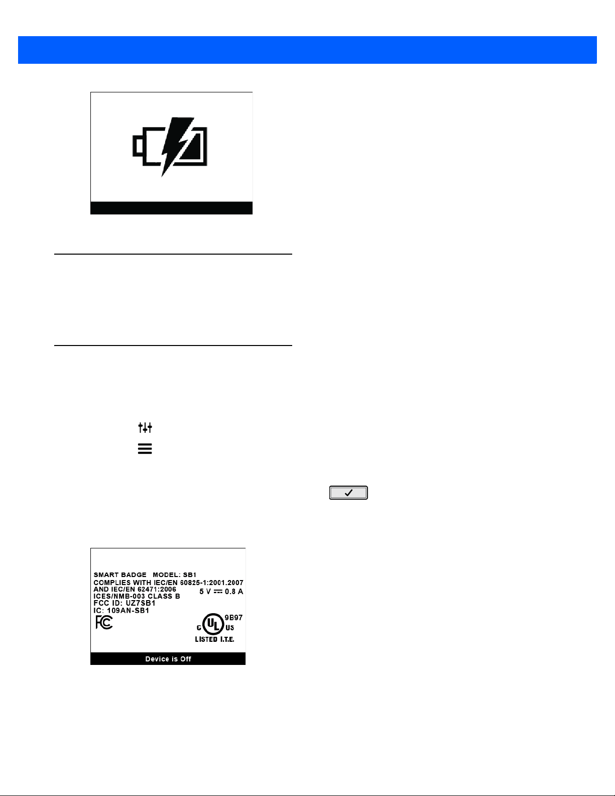
battery by placing it into a charging cradle. The Battery Charging screen
appears on the display indicating that the battery is charging.
Getting Started 1 - 5
Figure 1-6
Battery Charging Screen
Resetting the SB1
If the SB1 stops responding to input, perform a reset. A reset stops all running applications and any unsaved
data is lost. Simultaneously press and hold the Home and Scan buttons for five seconds. When the SB1 beeps
release the buttons and then it resets.
Powering Off the SB1
Power off the SB1 when not using for long periods of time.
1. Press the Home button.
2. Touch . The Settings screen appears.
3. Touch . The More Settings screen appears.
4. Touch Advanced Settings.
5. If required, enter the Administrator PIN and touch . The Advanced Settings screen appears.
6. Touch Power Off Device.
7. Touch OK. The SB1 shuts down and the Regulatory Information screen appears.
Figure 1-7
To turn the SB1 back on, place the SB1 into a cradle.
Regulatory Information Screen

1 - 6 SB1 User Guide

CHAPTER 2 OPERATION
This chapter provides basic instructions for using the SB1.
Wearing the SB1
The SB1 can be worn on a lanyard around the neck, in a holster on the hip or on an armband.
Lanyard
The lanyard provides easy access to the SB1 and allows the SB1 to be used as an employee badge when not
in use.
Figure 2-1
SB1 on Lanyard

2 - 2 SB1 User Guide
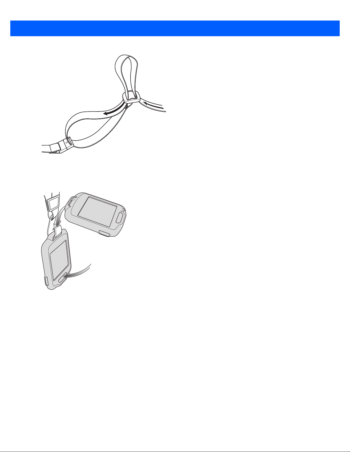
The SB1 mounts onto the lanyard and can be removed and replaced with ease. An accelerometer instantly
orients the screen 180° based on device position for easy viewing by customers and users.
The lanyard is adjustable allowing the user to position the SB1 to a
4-13.
Figure 2-2
Installing the SB1 onto the Lanyard
Holster
NOTE The tether on the holster is for loss prevention. Do not allow the SB1 to hang from the holster and drop to
the floor. Damage might occur.
comfortable height. See Lanyard on page
The holster clips onto a belt or waistband and provides a tether to secure the SB1. See Holster on page 4-9 for
setup instructions.
Figure 2-3
Holster on Belt
Operation 2 - 3
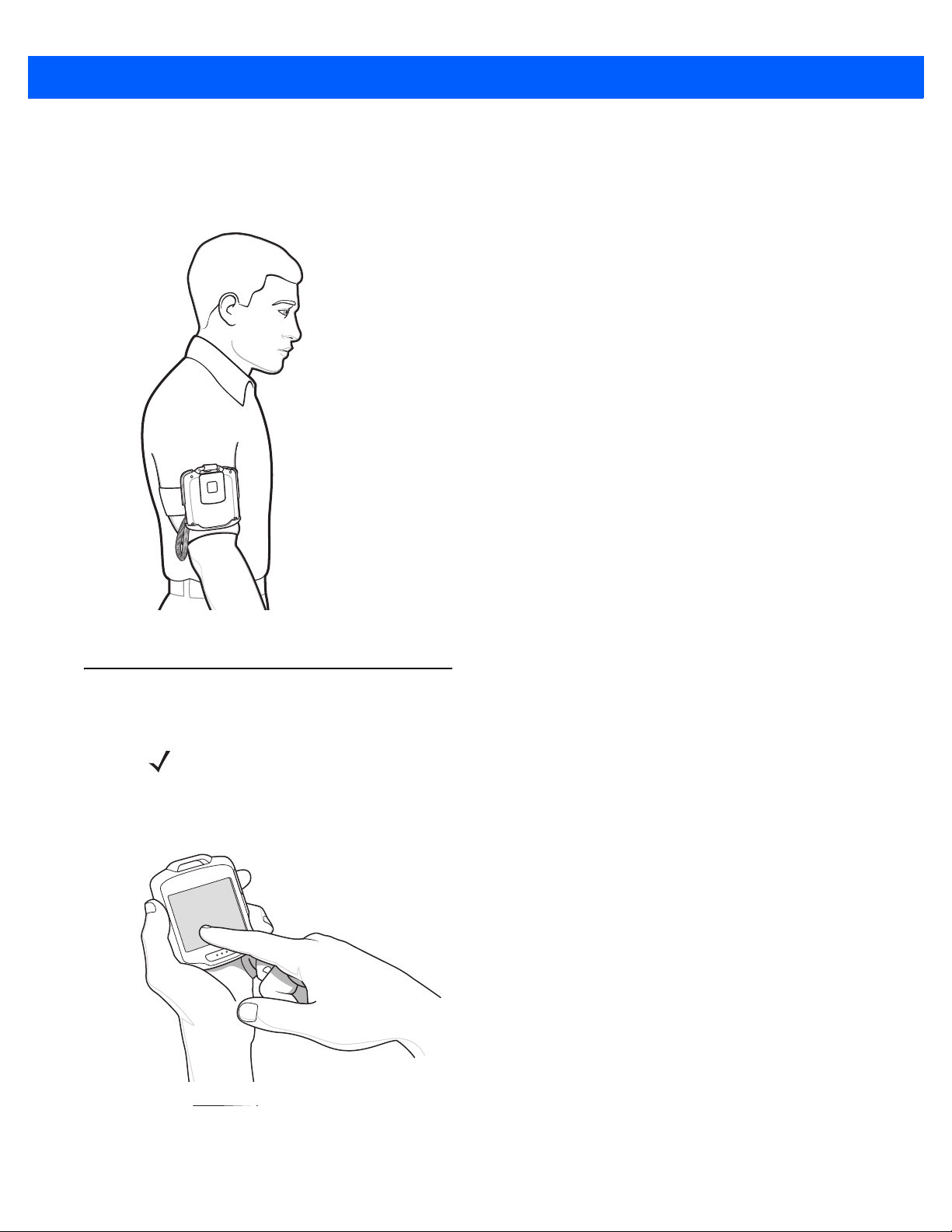
Armband
The armband attaches to the forearm or upper arm and provides mounting for the holster. See Armband on
page 4-11 for setup instructions.
Figure 2-4
Entering Data
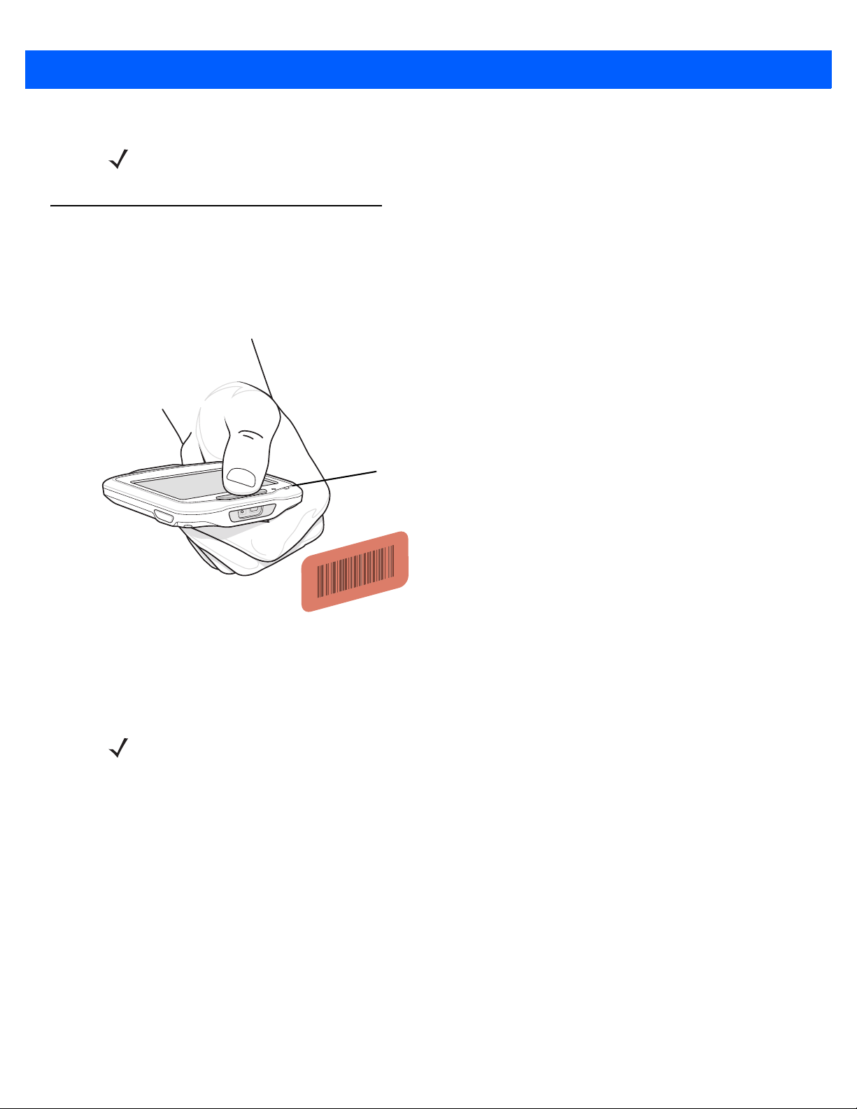
NOTE The user must only use a finger when touching the screen. Use of any other type of object could void the
The user uses the tip of their finger to select objects, enter text and accept notifications. Do not use a pen or
any other object on the SB1 display. It is designed for finger friendly touch only.
Armband
warranty.
Figure 2-5
Entering Data on Screen

2 - 4 SB1 User Guide
Audio Adapter
Using a Headset
One option for Push-to-Talk (PTT) communication is using a headset. Zebra offers two types of headset
accessories; earbud headset and speaker headset. The Headset Adapter is required when using a headset.
Connect the headset to the Headset Adapter when wearing the SB1 on the lanyard, holster or armband.
Figure 2-6
Using Headset with SB1 in Holster

Operation 2 - 5
Figure 2-7
Using Headset with SB1 on Lanyard
Figure 2-8
Headset with SB1 on Armband

2 - 6 SB1 User Guide
Microphone
PTT Button
Using the Speaker Adapter
The Speaker Adapter provides PTT communication. When receiving audio, the sound comes from the Speaker
Adapter. When the user speaks, the microphone on the front of the SB1 captures the audio.
Figure 2-9
Using the Speaker Adapter

Home Screen
Home Button
Notifications
User Profile Applications Settings
Lock
Running
Background
Application
The Home screen provides the user access to SB1 configuration, applications, notifications and user profile
settings.
Operation 2 - 7
Press and release the Home button on the side
NOTE When the SB1 is in a cradle, the Home screen does not display when the user presses the Home button.
Figure 2-10
Pressing Home Button
of the SB1 to display the Home screen.
Figure 2-11
Home Screen

2 - 8 SB1 User Guide
Table 2-1
Home Screen Icons
Icon Description
Notifications
notifications are available.
Lock
- Touch to automatically lock the SB1 and displays the User screen.
User Profile
Applications
Settings
- Touch to open the
- Touch to set user profile.
- Touch to launch the Applications screen.
- Touch to configure SB1 settings.
Notification
screen. A star on the icon indicates that new
Notifications
The SB1 displays notifications for system and application status. When a notification is received, a notification
dialog box appears on the screen and a beep sounds. The user can act on the notification or dismiss it
depending upon the notification.
Figure 2-12
If multiple notification
Figure 2-13
Touch one of the notifications to display its notification dialog b
Sample Notification Dialog Box
s are present, the SB1 displays a dialog box with each notification.
Multiple Notifications
ox. Touch to close the dialog box.

Operation 2 - 9
Title Text Box
Name Text Box
Notifications for Out of Network Coverage and Battery Low appear on the Home screen as icons. The user
also hears a single beep as the notification changes.
Figure 2-14
Out of Network Coverage and Battery Low Notifications
Locking the SB1
Touch the Lock icon to place the SB1 into badge mode. The screen automatically displays the user name and
title set in the Profile screen. The SB1 also goes into badge mode when it is hanging upside from a lanyard.
See Figure 2-1 on page 2-1.
Figure 2-15
To return to the Home screen, press the Home button.
Lock Screen
Setting User Profile
NOTE User settings may not be applicable for all applications. Check with system administrator.
Use the Profile screen to set the user name and user title, sign out of the SB1 and switch devices.
Figure 2-16
Profile Screen

2 - 10 SB1 User Guide
Enter Name and Title
To enter user name:
1. In the Profile screen, touch the top text box. The Enter Name screen appears.
Figure 2-17
2. Press the keypad keys to enter the user name.
3. Touch to save the name.
Enter Name Screen
• Use
ouch to display the numeric keypad.
• T
ouch to display special character keypad.
• T
o create the letter c, quickly touch three times.
• T
• Use
to create capital letter.
to delete the last character in the text box.
To enter user title:
1. In the Profile screen, touch the lower text box. The Enter Title screen appears.
Figure 2-18
2. Press keypad keys to enter the user title.
Enter Title Screen
• Use
ouch to display the numeric keypad.
• T
ouch to display special character keypad.
• T
o create the letter c, quickly touch three times.
• T
• Use
to create capital letter.
to delete the last character in the text box.

3. Touch to save the user title.
Log Out
This feature is dependant upon implementation.
Switch Device
This feature is dependant upon implementation.
Applications
All applications installed on the SB1 can be accessed by touching .
Operation 2 - 11
Figure 2-19
The Applications screen displays an icon for each application. If more than six applications are installed,
touch the arrow to move to the next page. Dots appear below the icons indicating the number of application
pages available.
Touch an icon to launch that application.
When there is a running application, an
screen and return to the last running application.
An
application.
Sample Applications Screen
NOTE The SB1 from the factory contains a limited number of applications. Once configured the SB1 may have
other applications installed.
appears in the title bar. Touch the to exit the Applications
appears on the top corner of all running application icons. Touch the on the icon to stop that
Figure 2-20
Sample Applications Screen with Running Application

2 - 12 SB1 User Guide
Back
WLAN Status
Menu
Beeper Volume Control
Audio Volume Control
Battery Status
PTT Express Settings
Settings
Use the Settings screen to control SB1 functionality.
Figure 2-21
•
•
•
•
•
•
Table 2-2
Icon Status Action
Settings Screen
WLAN Status - Displays the signal strength for the WLAN signal. See Table 2-2 on pag e 2-12. Touch the
icon to refresh the status.
NOTE After removing the SB1 from the cradle, it takes approximately 30 seconds for the battery status to update.
Battery Status - Displays the battery charge level. See Table 2 -3 on page 2-13. Touch the icon to refresh
the status.
Beeper Volume Control - Use to adjust the speaker volume. See Adjusting the Volume on page 2-13.
Audio Volume Control - Use to control the audio volume through the Headset Adapter and the Speaker
Adapter. See Adjusting the Volume on page 2-13. Note that when using a headset, the headset also has
a volume control.
PTT Express Settings - Touch to configure PTT Express for Push-to-Talk (PTT) settings. See PTT
Express Voice Client on page 2-15 for more information.
More Settings Menu - Touch to display additional setting options for setting the date and time,
screen calibration, prov
WLAN Status
isioning and wireless LAN configuration.
Excellent signal strength WLAN network is ready to use.
Very good signal strength WLAN network is ready to use.

Operation 2 - 13
Table 2-2
Icon Status Action
Table 2-3
WLAN Status (Continued)
Good signal strength WLAN network is
Poor signal strength WLAN network is ready to use. Performance may not be
optimum. Notify the network administrator that the signal
strength is “Poor”.
Out-of-network range (not
associated)
Battery Status
Icon Description
25%
50%
No WLAN network connection. The SB1 beeps and this icon
appears on the Home screen whenever it has lost or is out of
range from the wireless network. Notify the network
administrator. The SB1 beeps when it comes back in range of
the wireless network.
ready to use.
75%
100%
Adjusting the Volume
To adjust the beeper volume and the audio volume on the SB1, touch to increase volume or to
decrease volume. Note that when using a headset, the headset also
has a volume control.
PTT Express Settings
Use the PTT Express Setting to enable PTT Express and select a channel. For information on using PTT
Express see PTT Express Voice Client on page 2-15.
More Setting
Use the More Settings options to calibrate the screen, set beeper settings, view software versions and other
advanced settings.
Screen Calibration
If when touching the screen misalignment is observed, the user can re-calibrate the screen.
1. On the Settings screen, touch .
2. Touch Calibrate Screen.
3. Carefully press and briefly hold finger tip on the center of the target. Repeat the procedure as the target
moves and stops at different locations on the screen. This enters the new calibration settings.

2 - 14 SB1 User Guide
Figure 2-22
4. Once all of the new calibration settings are input, tap the screen to save the new calibration settings.
Calibration Screen
Beeper Settings
To set the alerts on the SB1. The user can select the type of notification that produces an audio alert:
1. Touch . The Settings screen appears.
2. Touch . The Advanced Settings screen appears.
3. Touch Beeper Settings.
4. Touch the System, Server or Application radio button to enable or disable the beeper sound when a
notification occurs.
5. Touch to return to the Home screen.
Software Versions
To view the versions of various software applications on the SB1, touch Software Versions. The Software
Version screen displays the version numbers for the operating system, RhoElements, App folder and the SB1
Shell.
Touch Back to return to the Mo
re Settings screen.
Advanced Setting
The Advanced Settings options provides settings that are configurable by a system administrator or
integrator. Advanced Settings are detailed in the SB1 Integrator Guide.

PTT Express Voice Client
PTT Button
Speaker
PTT Button
Volume Control
PTT Button
Volume Control
Microphone
Microphone
PTT Express Voice Client creates PTT communication capability between disparate enterprise devices.
Leveraging existing Wireless Local Area Network (WLAN) infrastructure, PTT Express delivers simple PTT
communication without the need of a voice communication server.
Operation 2 - 15
The Speaker Adapter or Headset Adapter and a Headset are required
Accessories for information on installing the adapters.
Figure 2-23
Speaker Adapter
for PTT communication. See Ch apter 4,
Figure 2-24
PTT Audible Indicators
The following tones provide helpful cues when using the voice client.
•
•
•
Headsets
Talk Tone: Double chirp. Plays when the PTT button (broadcast or private calls) is depressed. This is a
prompt for the user to start talking.
Access Tone: Single beep. Plays when another user just finished a broadcast or response to the user.
The user is now able to initiate a Group Broadcast or Private Response.
Busy Tone: Continuous tone. Plays when the broadcast (or private) button is depressed and another
user is already communicating on the same talkgroup.
2 - 16 SB1 User Guide
•
Network Tone:
ree increasing tones. Plays when PTT Express is acquiring the WLAN connection and ready for
• Th
voice communication.
• Th
ree decreasing tones. Plays when PTT Express has lost the WLAN connection and is not ready for
voice communication.
PTT Express Voice Client Configuration
Enable Voice Client Communication
To enable the PTT communication:
1. Press the Home button to display the Home screen.
2. Touch . The Settings screen appears.
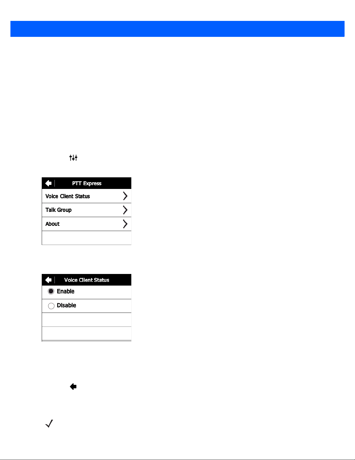
3. Touch PTT Express settings. The PTT Express screen appears.
Figure 2-25
4. Touch Voice Client Status.
Figure 2-26
5. Touch Enable.
6. Touch Save.
7. Touch .
PTT Express Screen
Voice Client Status Screen
Select a Talk Group
NOTE Upon reset, the talk group is set to Talk Group 1.
Operation 2 - 17
One of 32 talk groups can be selected by PTT Express users. However, only one talk group may be enabled at
a time on the SB1.
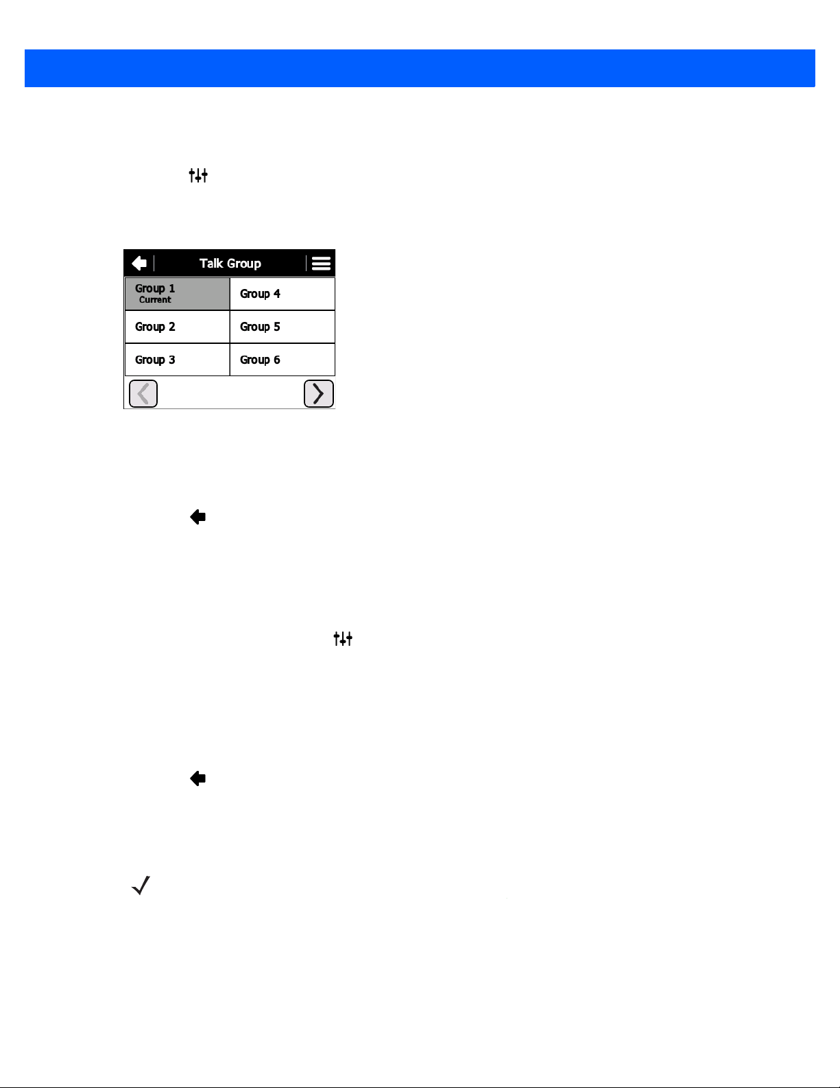
1. Touch . The Settings screen appears.
2. Touch PTT Express settings. The PTT Express screen appears.
3. Touch Talk Group. The Talk Group screen appears.
Figure 2-27
4. Touch a Talk Group number. Use the arrow buttons to view additional Talk Groups.
5. Touch Save.
6. Touch to return to the PTT Express screen.
7. Press the Home button.
Talk Group Screen
Disable PTT Express Voice Client Communication
To disable the PTT communication:
1. From the Home screen, touch . The Settings screen appears.
2. Touch PTT Express settings. The PTT Express screen appears.
3. Touch Voice Client Status.
4. Touch Disable.
5. Touch Save.
6. Touch to return to the PTT Express screen.
7. Press the Home button.
PTT Communication
NOTE By default, the Private Response feature is disabled. Specific applications may enabled this feature.
Check with system administrator for more information.
PTT communication may be established as a Group Broadcast or Private Response.
Group Broadcast (One to Many)
1. Press and hold the PTT button on the Speaker Adapter or Headset and listen for the talk tone to play.

2 - 18 SB1 User Guide
If a busy tone is heard, release the PTT button and wait a moment before making another attempt. Ensure
that PTT Express and the WLAN are enabled.
2. Start talking immediately after the talk tone plays.
NOTE If the user holds the PTT button for more than 60 seconds, the call is dropped and then
restarted preventing others from making Group Broadcast calls. The user should release the
Group Broadcast button when finished talking to allow others to make calls.
3. Release the PTT button when finished talking.
Response to a Group Broadcast
To respond to a Group Broadcast:
1. Wait until an access tone is heard.
2. Press and hold the PTT button within 300 msec. and listen for the talk tone to play.
If a busy tone is heard, release the PTT button and wait a moment
before making another attempt. Ensure
that PTT Express and the WLAN are enabled.
3. Start talking immediately after the talk tone plays.
4. Release the PTT button when finished talking.
Private Response (One to One)
NOTE By default, the Private Response feature is disabled. Specific applications may enabled this
feature. Check with system administrator for more information.
The Private Response can only be initiated once a Group Broadcast has been established.
The initial Private Response is mad
1. Wait until an access tone is heard.
2. Within 10 seconds, double press and hold the PTT button, and listen for the talk tone to play.
If a busy tone is heard, release the PTT button and wait a moment
that PTT Express and the WLAN are enabled.
3. Start talking immediately after the talk tone plays.
4. Release the PTT button when finished talking.
e to the last talker on the Group Broadcast.
before making another attempt. Ensure

CHAPTER 3 DATA CAPTURE
7.5 mil Code 39
20 mil Code 39
10 mil Data Matrix
10 mil PDF 417
13 mil 100% UPC
13 mil 80% UPC
2.50 in.
6.36 cm
2.67 in.
5.70 cm
2.02 in.
5.13 cm
2.54 in.*
6.45 cm *
1.64 in.*
4.17 cm *
2.76 in.*
7.01 cm*
5.41 in.
13.74 cm
7.98 in.
20.27 cm
8.57 in.
21.77 cm
9.36 in.
23.77 cm
13.47 in.
24.80 cm
20.67 in.
52.50 cm
* Dependent upon bar code width
Introduction
The SB1 contains a bar code reader with combined aimer and illumination for reading bar code data. The
reader uses advanced camera technology to take a digital picture of a bar code, and executes state-of-the-art
software decoding algorithms to extract the data from the image.
Scanning Considerations
Scanning consists of; aim, scan and decode. Scanning performance can be optimized by considering the
range.
Any scanning device decodes well over
bar code). This range varies according to bar code density and scanning device optics.
Scanning within range brings quick
decodes. Move the SB1 closer and further away to find the right working range for the bar codes being
scanned. The best way to specify the appropriate working range per bar code density is through a chart called
a decode zone. A decode graph simply plots working range as a function of minimum element widths of bar
code symbols. See the SB1 Integrator Guide for the detailed information.
Figure 3-1
a particular working range (minimum and maximum distances from the
and constant decodes; scanning too close or too far away prevents
Bar Code Reader Decode Graph
3 - 2 SB1 User Guide
LED
NOTE Contact the Zebra Global Customer Support if chronic scanning difficulties develop. Decoding of properly
printed bar codes should be quick and effortless.
Bar Code Reading
To read bar codes:
1. Ensure that the SB1 is loaded with a scanning application.
2. Aim the exit window at the bar code.
Figure 3-2
3. Press the Scan button. Ensure the red illumination covers the entire bar code. The LED Indicator
Data Capture
illuminates red to indicate that the illumination is on. The LED Indicator turns green and a beep sounds to
indicate a successful decode.
NOTE Scanning procedures depend on the application. An application may use different scanning procedures
from the one listed above.

Chapter 4 Accessories
Introduction
The SB1 accessories provide a variety of product support capabilities. Table 4-1 lists the SB1 accessories.
Table 4-1
Cradles
Single Slot Charging Cradle Charges the battery within the SB1.
Ten Slot Charge Only Cradle Charges up to ten SB1s.
Charging
Power Supply (12 VDC, 4.16 A) Provides power to the Ten Slot Charge Only Cradle.
Power Supply (5 VDC, 850 mA) Provides power to the Single Slot Charging Cradle.
Miscellaneous
Holster Provides a clip-on holder for the SB1.
Armband Provides a way to mount the holster for the SB1 on your arm.
Lanyard Use to hold the SB1 arou
Headset Adapter Provides audio to a wired headset.
Speaker Adapter Provides speaker for Push-To-Talk functionality.
Earbud Headset Provides audio for hands-free PTT conversations. Contains ear fit
SB1 Accessories
Accessory Description
nd your neck.
speaker, PTT button and volume control.

4 - 2 SB1 User Guide
Single Slot Charging Cradle
CAUTION Ensure to follow the guidelines for battery safety described in Battery Safety Guidelines on page 5-1.
Use the Single Slot Charging cradle to charge the SB1 battery. To charge the SB1 battery:
Figure 4-1
1. If attached, remove the SB1 from the lanyard or holster tether.
2. Slide the SB1 into the slot with the Scan button facing up and the display facing out.
Single Slot USB Cradle
NOTE If an Headset Adapter or Speaker Adapter is attached to the SB1 when placed into the cradle, the SB1
beeps indicating that the audio functionality has been disabled.
If the SB1 is playing audio when it is inserted into the cradle, the audio is muted and un-muted when the
SB1 is removed from the cradle.

LED Scan Button
Accessories 4 - 3
Figure 4-2
The Charging screen displays and
battery charges in approximately four hours. See Table 1-1 on page 1-4 for charging status indications.
3. When charging is complete, the SB1 may be removed from the cradle.
Single Slot USB Cradle
the SB1 LED Indicator indicates the SB1 battery charging status. The

4 - 4 SB1 User Guide
Ten Slot Charge Only Cradle
CAUTION Ensure that you follow the guidelines for battery safety described in Battery Safety Guidelines on page
5-1.
Use the Ten Slot Charge Only cradle to charge up to ten SB1s simultaneously. To charge the SB1:
Figure 4-3
1. If attached, remove the SB1 from the lanyard or holster tether.
2. Slide the SB1 into the slot with the Scan button facing up.
3. Push down on the SB1 until it snaps into place. Verify the SB1 is secure in the slot.
Ten Slot Charge Only Cradle
NOTE If an Headset Adapter or Speaker Adapter is attached to the SB1 when placed into the cradle, the SB1
beeps indicating that the audio functionality has been disabled.
If the SB1 is playing audio when it is i
SB1 is removed from the cradle.
nserted into the cradle, the audio is muted and un-muted when the

LED Scan Button
Accessories 4 - 5
Figure 4-4
The Charging screen displays and
Insert SB1 into Ten Slot Charge Only Cradle
the SB1 LED Indicator indicates the SB1 battery charging status. The
battery charges in approximately four hours. See Table 1-1 on page 1-4 for charging status indications.
4. When charging is complete, the SB1 may be removed from the cradle.

4 - 6 SB1 User Guide
Magnets
Headset Adapter
Use the Headset Adapter to add audio functionality to the SB1. To attach the Headset Adapter to the SB1:
1. Plug a headset plug into the headset jack on the Headset Adapter.
Figure 4-5
2. Align the Headset Adapter magnets with the adapter mounting points on the back of the SB1.
Attach Headset Jack to Headset Adapter
Figure 4-6
3. Lower the Headset Adapter onto the SB1. The Headset Adapter snaps onto the SB1. The SB1 sounds two
beeps to indicate that the adapter is connected properly.
4. Ensure the adapter is laying flat on the SB1. If not, remove and re-attach.
Align Headset Adapter with SB1

Accessories 4 - 7
Figure 4-7
To remove the Headset Adapter fro
SB1 and lift.
Figure 4-8
Headset Adapter on SB1
Remove Headset Adapter
m the SB1, grasp the edge of the Headset Adapter at the top edge of the

4 - 8 SB1 User Guide
Magnets
Speaker Adapter
Use the Speaker Adapter to add audio and Push-to-Talk functionality.
To install the Speaker Ad
1. Slide the Speaker Adapter onto the SB1 from the side ensuring that the Home button wraps about the SB1.
Figure 4-9
2. Lower the Speaker Adapter onto the SB1. The Speaker Adapter snaps onto the SB1. The SB1 sounds
three beeps to indicate that the adapter is connected properly.
Align Speaker Adapter
apter onto the SB1:
3. Ensure the adapter is laying flat on the SB1. If not, remove and re-attach.
Figure 4-10
Speaker Adapter Installed
NOTE When removing the Speaker Adapter from the SB1, the SB1 beeps indicating that the Speaker Adapter
has been removed from the SB1.
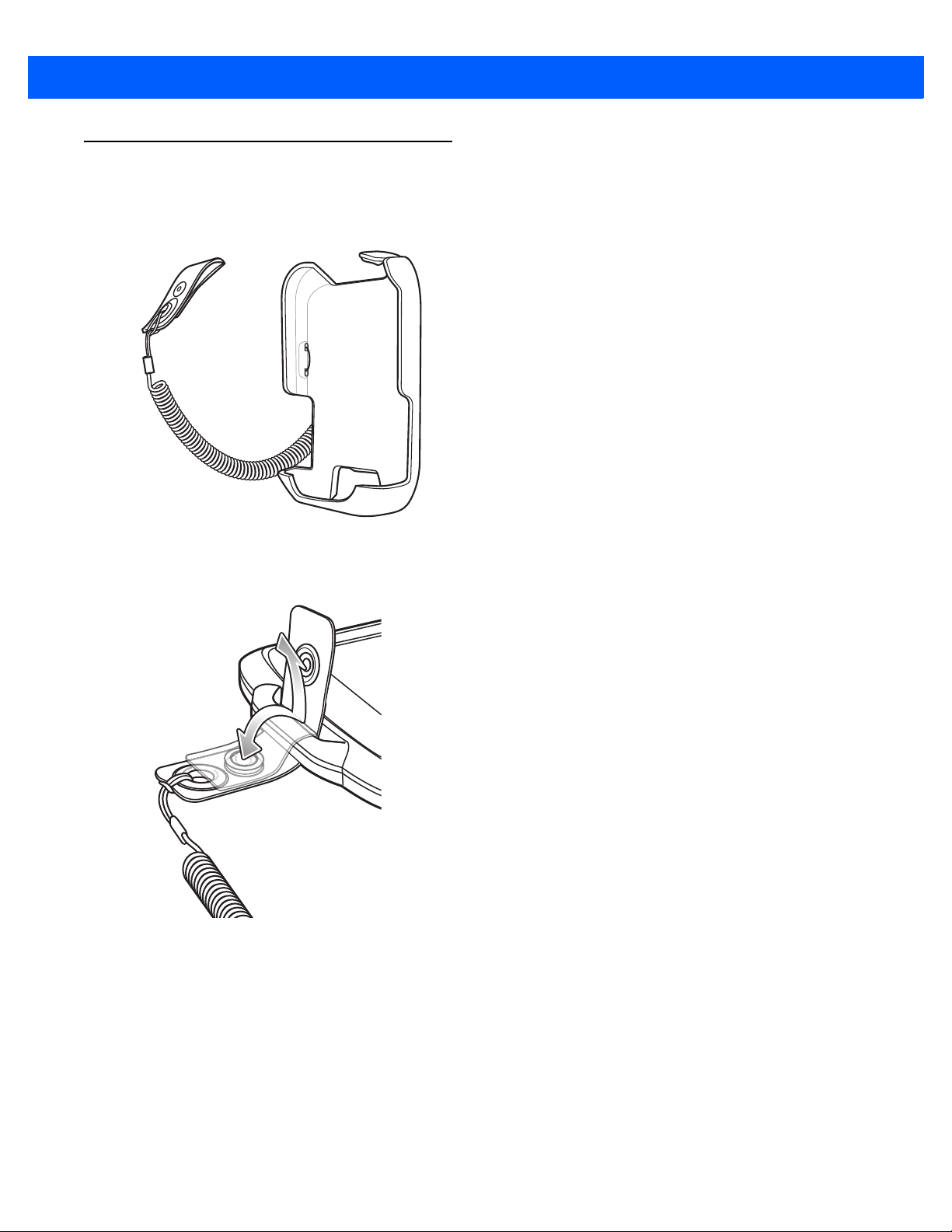
Holster
Use the holster to store the SB1 when not in use. The holster holds the SB1 on a belt or waist band and
provides a tether to attach the SB1 to the holster.
Accessories 4 - 9
Figure 4-11
Feed the clip end through the lanyard slot and snap together.
Figure 4-12
Place the SB1 into the holster with the Scan bu
Holster
Install Clip onto SB1
tton facing down and the screen facing the holster.
Push the SB1 into the holster until it snaps into place.

4 - 10 SB1 User Guide
Figure 4-13
To remove the SB1 from the holster
Install SB1 onto Holster
, pull on the top of the SB1 away from the body.
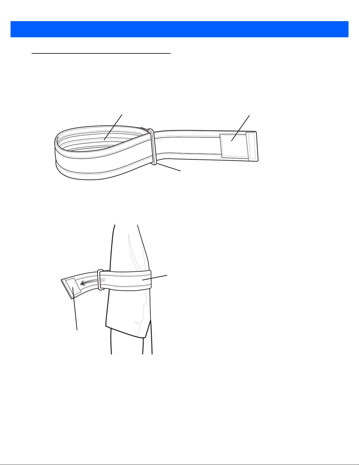
Armband
Hook Material
Rubber Grip Material
Buckle
Loop Material
Hook Material
Use the Armband to wear the SB1 on the arm.
To install the armband:
Accessories 4 - 11
Feed the end of the armband through
Figure 4-14
1. Slide the armband onto the arm to a comfortable location.
2. Pull the end of the armband and fold over so that the hook material attaches to the loop material.
Armband
the buckle ensuring that the rubber grip side is facing inside.
Figure 4-15
3. Insert the clip of the holster in between the two sections of the armband.
Install Armband

4 - 12 SB1 User Guide
Figure 4-16
4. Lift and then pull the end of the armband to tighten.
Insert Holster
Figure 4-17
Tighten Armband
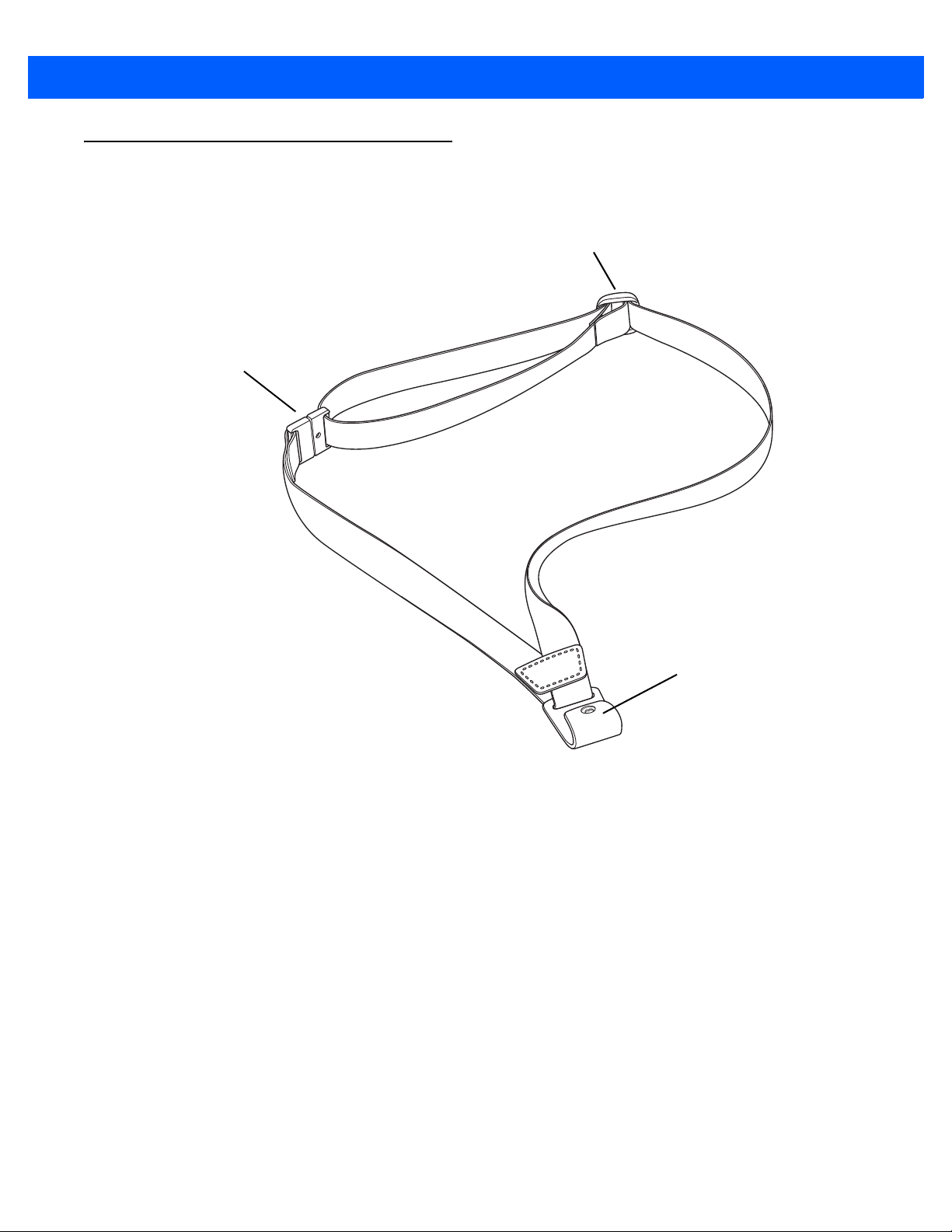
Lanyard
Breakaway Snap
J-hook
Adjustment Buckle
The lanyard provide a means to hold the SB1 around the neck.
Accessories 4 - 13
Figure 4-18
Slide the lanyard strap through the
closer to the Breakaway Snap lengthens the lanyard and moving it away from the Breakaway Snap shortens
the lanyard.
Lanyard
Adjustment Buckle to adjust the length of the lanyard. Moving the buckle
4 - 14 SB1 User Guide
Figure 4-19
The SB1 mounts onto the lanyard and can
orients the screen 180° based on device position for easy viewing by customers and users.
Figure 4-20
Adjust Lanyard
be removed and replaced with ease. An accelerometer instantly
Installing the SB1 onto the Lanyard

Chapter 5 Maintenance & Troubleshooting
Introduction
This chapter includes instructions on cleaning and storing the SB1, and provides troubleshooting solutions for
potential problems during SB1 operation.
Maintaining the SB1
For trouble-free service, observe the following tips when using the SB1:
•
Do not scratch the screen of the SB1. When working with the SB1, use only your finger. Never use an
actual pen, pencil, stylus or other sharp object on the surface of the SB1 screen.
•
Although the SB1 is water and dust resistant, do not expose it to rain or moisture for an extended period
of time. In general, treat the SB1 as a pocket calculator or other small electronic instrument.
•
The screen of the SB1 is glass. Do not to drop the SB1 or subject it to strong impact.
•
Protect the SB1 from temperature extremes. Do not leave it on the dashboard of a car on a hot day, and
keep it away from heat sources.
•
Do not store or use the SB1 in any location that is dusty, damp, or wet.
•
Use a soft lens cloth to clean the SB1. If the surface of the SB1 screen becomes soiled, clean it with a
soft cloth moistened with a diluted window-cleaning solution. See Cleaning on page 5-2.
•
Do not place in pocket. Use holster or armband.
Battery Safety Guidelines
WARNING! Failure to follow these guidelines may result in fire, explosion, or other hazard.
•
The area in which the units are charged should be clear of debris and combustible materials or
chemicals. Particular care should be taken where the device is charged in a non commercial
environment.

5 - 2 SB1 User Guide
•
Follow battery usage, storage, and charging guidelines found in this user guide.
•
Improper battery use may result in a fire, explosion, or other hazard.
•
To charge the mobile device battery, the battery and charger temperatures must be between +32 ºF and
+95 ºF (0 ºC and +35 ºC)
•
Do not use incompatible batteries and chargers. Use of an incompatible battery or charger may present a
risk of fire, explosion, leakage, or other hazard. If you have any questions about the compatibility of a
battery or a charger, contact Zebra Global Customer Support.
•
Do not disassemble or open, crush, bend or deform, puncture, or shred.
•
Severe impact from dropping any battery-operated device on a hard surface could cause the battery to
overheat.
•
Do not short circuit a battery or allow metallic or conductive objects to contact the battery terminals.
•
Do not modify or remanufacture, attempt to insert foreign objects into the battery, immerse or expose to
water or other liquids, or expose to fire, explosion, or other hazard.
•
Do not leave or store the equipment in or near areas that might get very hot, such as in a parked vehicle
or near a radiator or other heat source. Do not place battery into a microwave oven or dryer.
•
Battery usage by children should be supervised.
•
Please follow local regulations to properly dispose of used re-chargeable batteries.
•
Do not dispose of batteries in fire.
•
In the event of a battery leak, do not allow the liquid to come in contact with the skin or eyes. If contact
has been made, wash the affected area with large amounts of water and seek medical advice.
•
If you suspect damage to your equipment or battery, contact Zebra Global Customer Support to arrange
for inspection.
Cleaning
CAUTION Always wear eye protection.
Read warning label on compressed air and alcohol product before using.
If you have to use any other solution for medical reasons please contact Zebra for more information.
WARNING! Avoid exposing this product to contact with hot oil or other flammable liquids. If such
exposure occurs, unplug the device and clean the product immediately in accordance with
these guidelines.
Approved Cleanser Active Ingredients
100% of the active ingredients in any cleaner must consist of one or some combination of the following:
isopropyl alcohol, bleach/sodium hypochlorite
1(see Important note below)
, hydrogen peroxide or mild dish soap.

Maintenance & Troubleshooting 5 - 3
IMPORTANT Use pre-moistened wipes and do not allow liquid to pool.
1
When using sodium hypochlorite (bleach) based products always follow the manufacturer's
recommended instructions: use gloves during application and remove the residue afterwards with a
damp alcohol cloth or a cotton swab to avoid prolonged skin contact while handling the device.
Due to the powerful oxidizing nature
prone to oxidization (corrosion) when exposed to this chemical in the liquid form (including wipes).
Avoid allowing any bleach based product to come in contact with the metal electrical contacts on the
device, the battery, or the cradle. In the event that these types of disinfectants come in contact with
metal on the device, prompt removal with alcohol-dampened cloth or cotton swab after the cleaning
step is critical.
of sodium hypochlorite, the metal surfaces on the device are
Harmful Ingredients
The following chemicals are known to damage the plastics on the SB1 and should not come in contact with the
device: ammonia solutions, compounds of amines or ammonia; acetone; ketones; ethers; aromatic and
chlorinated hydrocarbons; acqueous or alcoholic alkaline solutions; ethanolamine; toluene; trichloroethylene;
benzene; carbolic acid and TB-lysoform.
Cleaning Instructions
Do not apply liquid directly to the SB1. Dampen a soft cloth or use pre-moistened wipes. Do not wrap the
device in the cloth or wipe, but gently wipe the unit. Be careful not to let liquid pool around the display window
or other places. Allow the unit to air dry before use.
Special Cleaning Notes
Many vinyl gloves contain phthalate additives, which are often not recommended for medical use and are
known to be harmful to the housing of the SB1. The SB1 should not be handled while wearing vinyl gloves
containing phthalates, or before hands are washed to remove contaminant residue after gloves are removed. If
products containing any of the harmful ingredients listed above are used prior to handling the SB1, such as
hand sanitizer that contain ethanolamine, hands must be completely dry before handling the SB1 to prevent
damage to the plastics.
Materials Required
•
Alcohol wipes
•
Lens tissue
•
Cotton tipped applicators
•
Isopropyl alcohol
•
Can of compressed air with a tube.
Cleaning the SB1
Housing
Using the alcohol wipes, wipe the housing including buttons.

5 - 4 SB1 User Guide
Display
The display can be wiped down with the alcohol wipes, but care should be taken not to allow any pooling of
liquid around the edges of the display. Immediately dry the display with a soft, non-abrasive cloth to prevent
streaking.
Reader Exit Window
Wipe the exit window periodically with a lens tissue or other material suitable for cleaning optical material such
as eyeglasses.
Contacts
1. Dip the cotton portion of the cotton tipped applicator in isopropyl alcohol.
2. Rub the cotton portion of the cotton tipped applicator back-and-forth across the contacts. Do not leave any
cotton residue on the contacts.
3. Repeat at least three times.
4. Use the cotton tipped applicator dipped in alcohol to remove any grease and dirt near the contacts.
5. Use a dry cotton tipped applicator and repeat steps 4 through 6.
CAUTION Do not point nozzle at yourself and others, ensure the nozzle or tube is away from your face.
6. Spray compressed air on the contact area by pointing the tube/nozzle about ½ inch away from the surface.
7. Inspect the area for any grease or dirt, repeat if required.
Cleaning Cradle Connectors
To clean the connectors on a cradle:
1. Remove the DC power cable from the cradle.
2. Dip the cotton portion of the cotton tipped applicator in isopropyl alcohol.
3. Rub the cotton portion of the cotton tipped applicator along the pins of the connector. Slowly move the
applicator back-and-forth from one side of the connector to the other. Do not let any cotton residue on the
connector.
4. All sides of the connector should also be rubbed with the cotton tipped applicator.
CAUTION Do not point nozzle at yourself and others, ensure the nozzle or tube is away from your face.
5. Spray compressed air in the connector area by pointing the tube/nozzle about ½ inch away from the
surface.
6. Ensure that there is no lint left by the cotton tipped applicator, remove lint if found.
7. If grease and other dirt can be found on other areas of the cradle, use lint free cloth and alcohol to remove.
8. Allow at least 10 to 30 minutes (depending on ambient temperature and humidity) for the alcohol to air dry
before applying power to cradle.

Maintenance & Troubleshooting 5 - 5
If the temperature is low and humidity is high, longer drying time is required. Warm temperature and dry
humidity requires less drying time.
Cleaning Frequency
The cleaning frequency is up to the customer’s discretion due to the varied environments in which the mobile
devices are used. They may be cleaned as frequently as required. However when used in dirty environments it
may be advisable to periodically clean the scanner exit window to ensure optimum scanning performance.

5 - 6 SB1 User Guide
Troubleshooting
SB1
Table 5-1
SB1 does not turn on. Battery not charged. Charge the SB1.
Battery did not charge. Battery failed. Perform a reset. For more information see,
SB1 does not emit
sound.
Troubleshooting the SB1
Problem Cause Solution
SB1 was turned off. Place the SB1 into a powered cradle. The SB1 turns on
when power is applied.
System error. Perform a reset. If the SB1 still does not turn on, contact the
system administrator. For more information see,
SB1 removed from
cradle while battery
was charging.
Extreme battery
temperature.
SB1 was placed in
the cradle upside
down.
Volume setting is low
or turned off.
the SB1 on page 1-5
SB1 on page 1-5
Place in cradle and begin charging. The battery requires up
to four hours to recharge fully.
Battery does not charge if ambient temperature is below
0
°C (32 °F) or above 35 °C (95 °F).
Remove the SB1 from the cradle and insert with Scan button
facing up.
Increase the volume. See
2-13
for more information.
.
.
Adjusting the Volume on page
Resetting
Resetting the
Tapping the screen
buttons or icons does
not activate the
corresponding feature.
Headset Adapter not
installed properly.
Headset not plugged
into Adapter correctly.
Speaker Adapter not
installed properly.
Touch screen not
calibrated correctly.
Battery depleted. Recharge the battery.
Remove and replace Headset Adapter. When connected
properly the SB1 emits two beeps.
Remove headset plug and insert into Headset Adapter audio
jack.
Remove and replace Speaker Adapter. When connected
properly the SB1 emits three beeps.
Re-calibrate the screen. See
2-13
.
Screen Calibration on page

Maintenance & Troubleshooting 5 - 7
Table 5-1
Cannot capture bar
c
ode data.
Troubleshooting the SB1 (Continued)
Problem Cause Solution
Scanning application
is not running.
Unreadable bar code. Ensure that the bar code is of good quality.
Distance between
SB1
incorrect.
SB1 is not
programmed for the
code type.
bar
Battery is low. Check the battery level. When the battery is low, the SB1
Bar Code Reader
dow is dirty.
win
Single Slot Charging Cradle
Table 5-2
Troubleshooting the Single Slot Charging Cradle
and bar code is
Verify the SB1 a scanning application is running. See the
system administrator.
Ensure that the SB1 is within proper scanning range.
See system administrator.
automatica
Clean the window. See
lly goes into suspend mode.
Cleaning on page 5-2
.
Problem Cause Solution
SB1 battery is not
charging.
Cradle is not receiving power. Ensure the power cable is connected securely to
both the cradle and to AC power.
The SB1 is not fully seated in
the cradle.
SB1 was placed in the cradle
side down.
up
Battery is faulty. Verify that other SB1 devices charge properly
Remove and re-insert the SB1 into the cradle,
uring it is correctly seated.
ens
Remove the SB1 from the cradle and insert with
Scan button facing up.
contact system administrator.
Ten Slot Charge Only Cradle
Table 5-3
SB1 battery is not charging. Cradle is not receiving power. Ensure the power cable is connected securely
Troubleshooting the Four Slot Charge Only Cradle
Problem Cause Solution
to both the cradle and to AC power.
The SB1 is not fully seated in
cradle.
the
Remove and re-insert the SB1 into the cradle,
ensuring it is correctly seated.
. If so,
SB1 was placed in the cradle
ide down.
ups
Battery is faulty. Verify that other SB1 devices charge properly.
Remove the SB1 from the cradle and insert
with Scan button facing up.
If so, contact system administrator
.

5 - 8 SB1 User Guide
Headset Adapter
Table 5-4
Audio cannot be heard
through headset.
Troubleshooting the Headset Adapter
Problem Cause Solution
Speaker Adapter
Table 5-5
Audio cannot be heard
through Speaker Adapter.
Troubleshooting the Speaker Adapter
Problem Cause Solution
Headset Adapter not
connected properly.
Headset is not connected
perly.
pro
Volume is too low. Increase audio volume.
Speaker Adapter not
connected properly.
Volume is too low. Increase audio volume,
Remove Headset Adapter and reinstall.
Remove headset from Headset Adapter and
reinstall.
Remove Speaker Adapter and reinstall.

Appendix A Sample Applications
This appendix provides information on the sample applications loaded on the SB1:
•
Demo-MVM
•
Demo-Scan
•
FTP.
Demo-MVM
The Demo-MVM application demonstrates using the SB1 is a workforce management application.
1. Touch > .
2. The splash screen appears followed by the Enter Password screen.
Figure A-1
3. Enter 123456 and then touch . The Inbox appears.
Splash Screen/Enter Password Screen

Task In-progress
Task Not Assigned
Task Assigned - Not Started
A - 2 SB1 User Guide
Figure A-2
Inbox Screen
Price Check Scenario
The Price Check scenario illustrates a task that has already been accepted by the user, the user has already
started the task and the user completes the task.
1. Touch Price Check. The Price Check screen appears.
Figure A-3
2. Point the SB1 at a bar code on a product.
3. Press the Scan button. The SB1 reads the bar code and displays information about the product.
Price Check Task Screen
Figure A-4
Touch
Product Data Screen
when the task is completed, to go back to the Inbox or to pause the task and
complete at a later time.
4. Touch to indicate that the task is complete.
5. Touch OK to confirm task completion.
6. Touch OK.
Sample Applications A - 3
7. The Inbox re-displays.
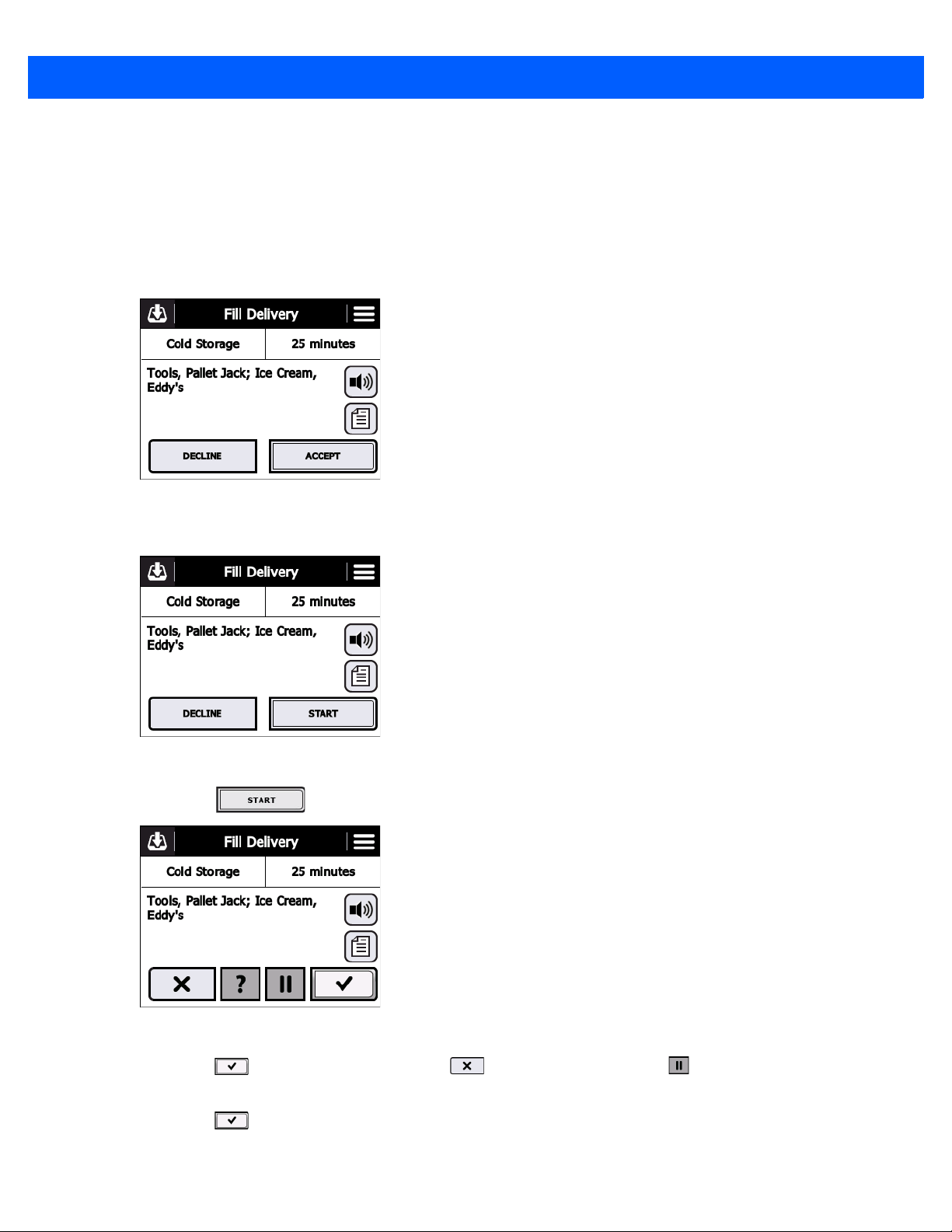
Fill Delivery Scenario
The Fill Delivery scenario illustrates a task that has not been accepted by the user, the user accepts the task
and then the user completes the task.
1. Touch Fill Delivery. The Fill Delivery screen appears.
Figure A-5
2. Touch Accept to accept the task.
Figure A-6
3. Touch to start the task.
Fill Delivery Screen
T ask Accepted Screen
Figure A-7
Touch
Task Started
when the task is completed, to go back to the Inbox or to pause the task and
complete at a later time.
4. Touch to indicate that the task is complete.
5. Touch OK to confirm task completion.

A - 4 SB1 User Guide
6. The Inbox re-displays with the task removed from the InBox.
Figure A-8
Fill Delivery Task Removed from Inbox
Unload Truck Scenario
The Unload Truck scenario illustrates a task that has been accepted by the user and the user completes the
task.
1. In the Inbox, touch Unload Truck. The Unload Truck screen appears.
Figure A-9
2. Touch to start the task.
Accepted Task Screen
Figure A-10
Touch
Task Started Screen
when the task is completed, to go back to the Inbox or to pause the task and
complete at a later time.
3. Touch to indicate that the task is complete.
4. Touch OK to confirm task completion.
5. The Inbox re-displays with the Unload Truck task removed from the InBox.

Sample Applications A - 5
Figure A-11
Unload Truck Removed from Inbox
Collect Carts Scenario
The Collect Cart scenario illustrates a task that has been assigned to the user, the user pauses the task and
then go back to complete the task.
1. In the Inbox, touch Collect Carts. The Collect Carts screen appears.
Figure A-12
2. Touch to start the task.
Accepted Task Screen
Figure A-13
Collect Carts Task Started
Touch
a later time.
3. Touch .
when the task is completed, to cancel the task or to pause the task and complete at
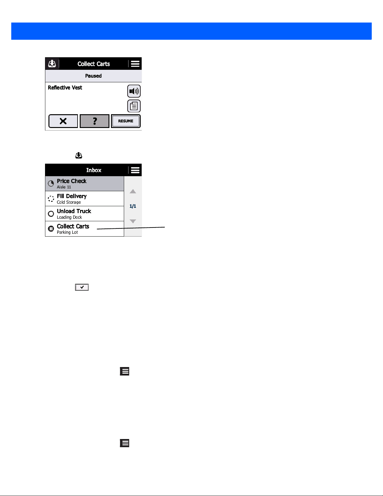
A - 6 SB1 User Guide
Task Paused
Figure A-14
4. Touch .
Figure A-15
5. Touch Collect Carts.
6. Touch Resume.
7. Touch to indicate that the task is complete.
8. Touch OK to confirm task completion.
9. Touch OK.
Collect Carts Task Paused
Inbox Collect Carts Task Paused
10. The Inbox re-displays with the task removed from the InBox.
Reset Sales Demo
While using the Sales Demo application, the data can be reset to its initial state.
1. From the Inbox, touch .
2. Touch Reset demo.
3. The Inbox appears with the data reset to the initial settings.
Exit Sales Demo
To exit the Sales Demo:
1. From the Inbox, touch .
2. Touch Exit demo.
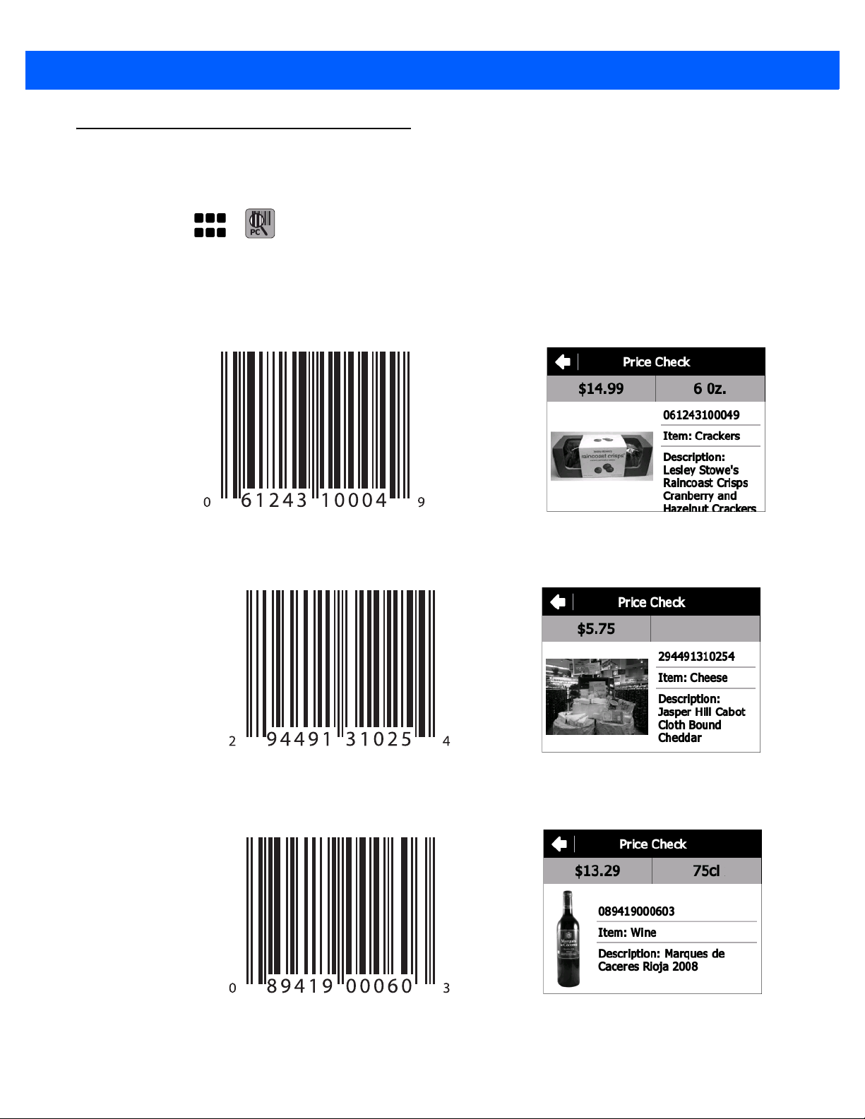
Demo-Scan
Use the Demo-Scan application to demonstrate how a price look-up application functions.
1. Touch > . The Price Check screen appears.
2. Press the Scan button and scan one of the bar code below. Upon successful decode the corresponding
product information screen displays.
3. Press the Back button to return to the main Price Check screen.
Sample Applications A - 7
Figure A-16
Figure A-17
Crackers
Cheese
Figure A-18
Wine

A - 8 SB1 User Guide
Figure A-19
Figure A-20
Jeans - Size 14R
Jeans - Size 3
Figure A-21
Camera

Sample Applications A - 9
Figure A-22
Figure A-23
Camera Case
Memory Card
FTP Client
Use the FTP application to transfer files between an ftp server to the SB1.
Touch
Figure A-24
> . The FTP screen appears.
FTP Application Screen

A - 10 SB1 User Guide
Required
•
FTP server software
•
SB1
Setup
Make sure the SB1 is connected to the network and has a valid IP Address on the same network as the FTP
server.
NOTE The Run button should not be used.
There are 4 fields in th
•
IP Address of the FTP server
•
File to transfer
•
User Name (leave blank if no credentials required)
•
Password (leave blank if no credentials required).
To transfer a file to t
1. Fill in the applicable fields, including the file to transfer.
2. Press Get.
3. File is transferred to the root of the SB1 UserDrive.
e application:
he SB1:
To transfer a file from the SB1:
1) Fill in the applicable fields, inc
luding the file to transfer.
2) Press Send.
3) File is transferred from
the root of the SB1 UserDrive to the ftp server.
Exit Application
To exit the FTP application, touch Close. The Application launcher screen appears.

Appendix B Specifications
This appendix provides specifications for the SB1 and accessories.
SB1 Technical Specifications
Table B-1 summarizes the SB1 technical specifications and intended operating environments.
Table B-1
Physical Characteristics
Dimensions 92 mm L x 81 mm W x 14 mm D
Weight 110 g (3.9 oz.)
Display 3.0” E Ink Pearl, 4-bit grayscale (16 shades). QVGA 320 x 240 resolution.
Touch Panel Full screen resistive touch; finger operation (no stylus)
Battery Rechargeable Lithium-ion 910 mAh
Network Connections Wireless Local Area Network (WLAN)
Notification Audio: beeper; Visual: multi-color LED
Audio Integrated microphone; accessories include optional Speaker Adapter with
Performance Characteristics
CPU IMX35 (532 MHz)
Applications Supports thin client applications and HTML 5 with RhoElements
SB1 Technical Specifications
Item Description
(3.62 in. L x 3.19 in. W x 0.55 in. D)
push-to-talk and Headset Adapter.
extensions.
Memory 128 MB RAM/128 MB Flash

B - 2 SB1 User Guide
Table B-1
User Environment
Operating Temperature 0 °C to 40°C (32 °F to 104 °F)
Storage Temperature -40 °C to 70 °C (-40 °C to 158 °F)
Charging Temperature 0 °C to 35 °C (32 °F to 95 °F)
Humidity 5 to 95% non-condensing
Drop Specification Multiple 1.22 m (4 ft) drop to tile over concrete per MIL STD 810G
Electrostatic Discharge (ESD) +/-15 kV air discharge
Sealing IP54
Wireless LAN Data and Voice Communications
WLAN radio
Data Rates Supported 1, 2, 5.5, 6, 9, 11, 12, 18, 24, 36, 48, 54 Mbps and MCS0-7
Operating Channels Channel 1-13 (2412-2472 MHz), Channel 14 (2484 MHz) Japan only;
SB1 Technical Specifications (Continued)
Item Description
specifications
+/- 8 kV direct discharge
Wi-Fi IEEE® 802.11b/g/n (2.4 GHz only)
actual operating channels/frequencies depend on regulatory rules and
certification agency
Security
Spreading Technique Direct Sequence Spread Spectrum (DSSS) and Orthogonal Frequency
Data Capture
Bar Code Reader Omni-directional bar code reader with integrated aiming and illumination.
Security Modes:
Encryption:
Authentication:
(CHAP), TTLS (MD5), TTLS (PAP), PEAP-TLS, PEAP (MS-CHAP v2),
PEAP (EAP-GTC), EAP-FAST-TLS, EAP-FAST (MS-CHAP v2), EAP-FAST
(EAP-GTC) and LEAP
Division Multiplexing (OFDM)
Legacy, WPA and WPA2
WEP (40 or 128 bit), TKIP and AES
TLS, TTLS (MS-CHAP), TTLS (MS-CHAP v2), TTLS

GLOSSARY
Numeric
802.11bgn. A radio protocol that may be used by the SB1 radio.
A
Access Point. Access Point (AP) refers to Zebra’s Ethernet Access Point. It is a piece of communications equipment
that manages communications between the host computer system and one or more wireless terminals. An AP
connects to a wired Ethernet LAN and acts as a bridge between the Ethernet wired network and IEEE 802.11
interoperable radio-equipped mobile units, such as a SB1. The AP allows a mobile user to roam freely through a
facility while maintaining a seamless connection to the wired network.
B
Bar Code. A pattern of variable-width bars and spaces which represents numeric or alphanumeric data in
machine-readable form. The general format of a bar code symbol consists of a leading margin, start character, data
or message character, check character (if any), stop character, and trailing margin. Within this framework, each
recognizable symbology uses its own unique format.
Bit. Binary digit. One bit is the basic unit of binary information. Generally, eight consecutive bits compose one byte of
data. The pattern of 0 and 1 values within the byte determines its meaning.
Bits per Second (bps). Bits transmitted or received.
Byte. On an addressable boundary, eight adjacent binary digits (0 and 1) combined in a pattern to represent a specific
character or numeric value. Bits are numbered from the right, 0 through 7, with bit 0 the low-order bit. One byte in
memory is used to store one ASCII character.
boot or boot-up. The process a device goes through when it starts. During boot-up, the device can run self-diagnostic
tests and configure hardware and software.

Glossary - 2 SB1 User Guide
C
Cradle. A cradle is used for charging the terminal battery and for communicating with a host computer, and provides a
storage place for the terminal when not in use.
D
Decode. To recognize a bar code symbology (e.g., UPC/EAN) and then analyze the content of the specific bar code
scanned.
E
ESD. Electro-Static Discharge
F
Flash Memory. Flash memory is responsible for storing the system firmware and is non-volatile. If the system power is
interrupted the data is not be lost.
H
Hz. Hertz; A unit of frequency equal to one cycle per second.
Host Computer. A computer that serves other terminals in a network, providing such services as computation,
database access, supervisory programs and network control.
I
IP. Internet Protocol. The IP part of the TCP/IP communications protocol. IP implements the network layer (layer 3) of
the protocol, which contains a network address and is used to route a message to a different network or subnetwork.
IP accepts “packets” from the layer 4 transport protocol (TCP or UDP), adds its own header to it and delivers a
“datagram” to the layer 2 data link protocol. It may also break the packet into fragments to support the maximum
transmission unit (MTU) of the network.
IP Address. (Internet Protocol address) The address of a computer attached to an IP network. Every client and server
station must have a unique IP address. A 32-bit address used by a computer on a IP network. Client workstations
have either a permanent address or one that is dynamically assigned to them each session. IP addresses are written
as four sets of numbers separated by periods; for example, 204.171.64.2.

Glossary - 3
L
LAN. Local area network. A radio network that supports data communication within a local area, such as within a
warehouse of building.
LED Indicator. A semiconductor diode (LED - Light Emitting Diode) used as an indicator, often in digital displays. The
semiconductor uses applied voltage to produce light of a certain frequency determined by the semiconductor's
particular chemical composition.
P
Push-to-Talk PTT. a method of communicating over wireless network using a momentary button to switch from voice
reception mode to transmit mode.
R
RAM. Random Access Memory. Data in RAM can be accessed in random order, and quickly written and read.
Reset. A reset restarts the SB1 by closing all running programs. All data that is not saved to flash memory is lost.
Resolution. The narrowest element dimension which is distinguished by a particular reading device or printed with a
particular device or method.
RF. Radio Frequency.
Router. A device that connects networks and supports the required protocols for packet filtering. Routers are typically
used to extend the range of cabling and to organize the topology of a network into subnets. See Subnet.
S
SB1. In this text, SB1 refers to the Zebra smart badge. It can be set up to run as a stand-alone device, or it can be set
up to communicate with a network, using wireless radio technology.
Scan Area. Area intended to contain a symbol.
Scanner. An electronic device used to scan bar code symbols and produce a digitized pattern that corresponds to the
bars and spaces of the symbol.
Scanning Mode. The bar code reader is energized, programmed and ready to read a bar code.
Subnet. A subset of nodes on a network that are serviced by the same router. See Router.
Subnet Mask. A 32-bit number used to separate the network and host sections of an IP address. A custom subnet mask
subdivides an IP network into smaller subsections. The mask is a binary pattern that is matched up with the IP
address to turn part of the host ID address field into a field for subnets. Default is often 255.255.255.0.

Glossary - 4 SB1 User Guide
Symbol. A scannable unit that encodes data within the conventions of a certain symbology, usually including start/stop
characters, quiet zones, data characters and check characters.
Symbology. The structural rules and conventions for representing data within a particular bar code type (e.g. UPC/EAN,
Code 39, PDF417, etc.).

INDEX
A
accessories . . . . . . . . . . . . . . . . . . . . . . . . . . . . . . . . 1-2
single slot charging cradle . . . . . . . . . . . . . . . . . 4-2
battery charging . . . . . . . . . . . . . . . . . . . . . . 4-2
ten slot charge only cradle . . . . . . . . . . . . . . . . . 4-4
ten slot cradles
battery charging . . . . . . . . . . . . . . . . . . . . . . 4-4
adjusting volume . . . . . . . . . . . . . . . . . . . . . . . . . . . 2-13
applications . . . . . . . . . . . . . . . . . . . . . . . . . . . . . . . 2-11
armband . . . . . . . . . . . . . . . . . . . . . . . . . . 2-3, 4-1, 4-11
audio adapter . . . . . . . . . . . . . . . . . . . . . . . . . . . . . . 4-6
audio volume . . . . . . . . . . . . . . . . . . . . . . . . . . . . . . 2-13
B
bar code reading . . . . . . . . . . . . . . . . . . . . . . . . . . . . 3-2
battery charging
temperature range . . . . . . . . . . . . . . . . . . . . . . . 1-3
battery charging screen . . . . . . . . . . . . . . . . . . . . . . 1-4
battery discharged screen . . . . . . . . . . . . . . . . . . . . . 1-4
beeper volume . . . . . . . . . . . . . . . . . . . . . . . . . . . . 2-13
bullets . . . . . . . . . . . . . . . . . . . . . . . . . . . . . . . . . . . . . . x
C
calibration . . . . . . . . . . . . . . . . . . . . . . . . . . . . . . . . 2-13
calibration screen . . . . . . . . . . . . . . . . . . . . . . . . . . . 1-3
charging, temperature range . . . . . . . . . . . . . . . . . . . 1-3
cleaning . . . . . . . . . . . . . . . . . . . . . . . . . . . . . . . . . . . 5-1
configuration . . . . . . . . . . . . . . . . . . . . . . . . . . . . . . . . . ix
conventions
notational . . . . . . . . . . . . . . . . . . . . . . . . . . . . . . . . x
cradles
single slot charging cradle
battery charging . . . . . . . . . . . . . . . . . . . . . . 4-2
ten slot charge only cradle . . . . . . . . . . . . . . . . . 4-4
ten slot cradles
battery charging . . . . . . . . . . . . . . . . . . . . . . 4-4
D
data capture . . . . . . . . . . . . . . . . . . . . . . . . . . . . . . . . . ix
decode zone . . . . . . . . . . . . . . . . . . . . . . . . . . . . . . . 3-1
display . . . . . . . . . . . . . . . . . . . . . . . . . . . . . . . . . . . . . ix
documentation updates . . . . . . . . . . . . . . . . . . . . . . . . xi
E
earbud headset . . . . . . . . . . . . . . . . . . . . . . . . . . . . . 4-1
employee badge . . . . . . . . . . . . . . . . . . . . . . . . . . . . 2-1
G
group broadcast . . . . . . . . . . . . . . . . . . . . . . . . . . . . 2-17
group response . . . . . . . . . . . . . . . . . . . . . . . . . . . . 2-18
H
headset . . . . . . . . . . . . . . . . . . . . . . . . . . . . . . . . . . . 2-4
headset adapter . . . . . . . . . . . . . . . . . . . . . . . . . . . . . 4-1
holster . . . . . . . . . . . . . . . . . . . . . . . . . . . . . 2-2, 4-1, 4-9
home screen . . . . . . . . . . . . . . . . . . . . . . . . . . . . . . . 2-7
I
information, service . . . . . . . . . . . . . . . . . . . . . . . . . . . xi
L
lanyard . . . . . . . . . . . . . . . . . . . . . . . . . . . . 2-1, 4-1, 4-13

Index - 2 SB1 User Guide
M
main battery . . . . . . . . . . . . . . . . . . . . . . . . . . . . . . . . 1-3
maintenance . . . . . . . . . . . . . . . . . . . . . . . . . . . . . . . 5-1
memory . . . . . . . . . . . . . . . . . . . . . . . . . . . . . . . . . . . . .ix
N
notifications . . . . . . . . . . . . . . . . . . . . . . . . . . . . . . . . 2-8
O
operating
environment . . . . . . . . . . . . . . . . . . . . . . . . . . . . B-1
P
parts . . . . . . . . . . . . . . . . . . . . . . . . . . . . . . . . . . . . . . 1-2
profile . . . . . . . . . . . . . . . . . . . . . . . . . . . . . . . . . . . . . 2-9
PTT Express . . . . . . . . . . . . . . . . . . . . . . . . . .2-14, 2-15
R
radios . . . . . . . . . . . . . . . . . . . . . . . . . . . . . . . . . . . . . . .ix
regulatory label . . . . . . . . . . . . . . . . . . . . . . . . . . . . . 1-3
resetting . . . . . . . . . . . . . . . . . . . . . . . . . . . . . . . . . . . 1-5
resetting the SB1 . . . . . . . . . . . . . . . . . . . . . . . . . . . . 1-5
ten slot charge only cradle . . . . . . . . . . . . . . . . . . 5-6
U
unpacking . . . . . . . . . . . . . . . . . . . . . . . . . . . . . . . . . . 1-1
updates, documentation . . . . . . . . . . . . . . . . . . . . . . . . xi
V
volume
audio . . . . . . . . . . . . . . . . . . . . . . . . . . . . . . . . . 2-13
beeper . . . . . . . . . . . . . . . . . . . . . . . . . . . . . . . . 2-13
S
sales demo application . . . . . . . . . . . . . . . . . . . . . . . A-1
scan button . . . . . . . . . . . . . . . . . . . . . . . . . . . . . . . . 1-2
scanning . . . . . . . . . . . . . . . . . . . . . . . . . . . . . . . . . . 3-1
scanning considerations . . . . . . . . . . . . . . . . . . . . . . 3-1
settings . . . . . . . . . . . . . . . . . . . . . . . . . . . . . . . . . . 2-12
single slot charging cradle . . . . . . . . . . . . . . 1-3, 4-1, 4-2
battery charging . . . . . . . . . . . . . . . . . . . . . . . . . 4-2
software version . . . . . . . . . . . . . . . . . . . . . . . . . . . 2-14
speaker adapter . . . . . . . . . . . . . . . . . . . . . . 2-6, 4-1, 4-8
speaker headset . . . . . . . . . . . . . . . . . . . . . . . . . . . . 4-1
storing . . . . . . . . . . . . . . . . . . . . . . . . . . . . . . . . . . . . 5-1
T
talk groups . . . . . . . . . . . . . . . . . . . . . . . . . . . . . . . . 2-17
technical specifications . . . . . . . . . . . . . . . . . . . . . . . B-1
temperature
charging . . . . . . . . . . . . . . . . . . . . . . . . . . . . . . . B-2
ten slot charge only cradle . . . . . . . . . . . . . . 1-3, 4-1, 4-4
ten slot cradles
battery charging . . . . . . . . . . . . . . . . . . . . . . . . . 4-4
troubleshooting . . . . . . . . . . . . . . . . . . . . . . . . . . . . . 5-5
SB1 . . . . . . . . . . . . . . . . . . . . . . . . . . . . . . . . . . . 5-5
single slot charging cradle . . . . . . . . . . . . . . . . . 5-6


Zebra Technologies Corporation
Lincolnshire, IL U.S.A
http://www.zebra.com
Zebra and the stylized Zebra head are trademarks of ZIH Corp., registered in many jurisdictions
worldwide. All other trademarks are the property of their respective owners.
©2015 ZIH Corp and/or its affiliates. All rights reserved.
72E-164711-04 Revision A - May 2019
 Loading...