

Page 1
S4M™
Industrial/Commercial Printer
User Guide
Page 2

© 2005 ZIH Corp.
The copyrights in this manual and the label printer described therein are owned by
Zebra Technologies Corporation. Unauthorized reproduction of this manual or the
software in the label printer may result in imprisonment of up to one year and
fines of up to $10,000 (17 U.S.C.506). Copyright violators may be subject to civil
liability.
This product may contain ZPL®, ZPL II®, and ZebraLink™ programs; Element
®
Energy Equalizer® Circuit; E
3
; and AGFA fonts. Software © ZIH Corp. All
rights reserved worldwide.
ZebraLink and all product names and numbers are trademarks, and Zebra, the
Zebra logo, ZPL, ZPL II, Element Energy Equalizer Circuit, and E3 Circuit are
registered trademarks of ZIH Corp. All rights reserved worldwide.
All other brand names, product names, or trademarks belong to their respective
holders.
Part Number: 13290L-001 Rev. A
Page 3

Contents
Contents . . . . . . . . . . . . . . . . . . . . . . . . . . . . . . . . . . . . . . . . . . . . . . . . . . . . . . . . . iii
About This Document . . . . . . . . . . . . . . . . . . . . . . . . . . . . . . . . . . . . . . . . . . . . . . . 1
Who Should Use This Document . . . . . . . . . . . . . . . . . . . . . . . . . . . . . . . . . . . . . . . . . . . . 2
How This Document Is Organized . . . . . . . . . . . . . . . . . . . . . . . . . . . . . . . . . . . . . . . . . . . 2
Contacts . . . . . . . . . . . . . . . . . . . . . . . . . . . . . . . . . . . . . . . . . . . . . . . . . . . . . . . . . . . . . . . 3
Web Site . . . . . . . . . . . . . . . . . . . . . . . . . . . . . . . . . . . . . . . . . . . . . . . . . . . . . . . . . . . . 3
The Americas . . . . . . . . . . . . . . . . . . . . . . . . . . . . . . . . . . . . . . . . . . . . . . . . . . . . . . . . 3
Europe, Africa, Middle East, and India . . . . . . . . . . . . . . . . . . . . . . . . . . . . . . . . . . . . . 3
Asia Pacific . . . . . . . . . . . . . . . . . . . . . . . . . . . . . . . . . . . . . . . . . . . . . . . . . . . . . . . . . . 3
Document Conventions. . . . . . . . . . . . . . . . . . . . . . . . . . . . . . . . . . . . . . . . . . . . . . . . . . . . 4
1 • Introduction . . . . . . . . . . . . . . . . . . . . . . . . . . . . . . . . . . . . . . . . . . . . . . . . . . . . 7
External View . . . . . . . . . . . . . . . . . . . . . . . . . . . . . . . . . . . . . . . . . . . . . . . . . . . . . . . . . . . 8
Control Panel . . . . . . . . . . . . . . . . . . . . . . . . . . . . . . . . . . . . . . . . . . . . . . . . . . . . . . . . . . . 9
Control Panel LCD . . . . . . . . . . . . . . . . . . . . . . . . . . . . . . . . . . . . . . . . . . . . . . . . . . . 10
Control Panel Buttons. . . . . . . . . . . . . . . . . . . . . . . . . . . . . . . . . . . . . . . . . . . . . . . . . 10
Control Panel Lights . . . . . . . . . . . . . . . . . . . . . . . . . . . . . . . . . . . . . . . . . . . . . . . . . . 12
Printer Media Compartment . . . . . . . . . . . . . . . . . . . . . . . . . . . . . . . . . . . . . . . . . . . . . . . 13
Printer Language Modes. . . . . . . . . . . . . . . . . . . . . . . . . . . . . . . . . . . . . . . . . . . . . . . . . . 14
Firmware Downloads . . . . . . . . . . . . . . . . . . . . . . . . . . . . . . . . . . . . . . . . . . . . . . . . . 14
New or Modified Commands . . . . . . . . . . . . . . . . . . . . . . . . . . . . . . . . . . . . . . . . . . . 14
Additional Printer Language Information . . . . . . . . . . . . . . . . . . . . . . . . . . . . . . . . . . 14
10/21/05 S4M User Guide 13290L-001 Rev. A
Page 4

Contents
iv
2 • Printer Setup . . . . . . . . . . . . . . . . . . . . . . . . . . . . . . . . . . . . . . . . . . . . . . . . . . 15
Before You Begin . . . . . . . . . . . . . . . . . . . . . . . . . . . . . . . . . . . . . . . . . . . . . . . . . . . . . . . 16
Unpack and Inspect the Printer. . . . . . . . . . . . . . . . . . . . . . . . . . . . . . . . . . . . . . . . . . . . . 17
Inspect the Printer. . . . . . . . . . . . . . . . . . . . . . . . . . . . . . . . . . . . . . . . . . . . . . . . . . . . 17
Report Shipping Damage . . . . . . . . . . . . . . . . . . . . . . . . . . . . . . . . . . . . . . . . . . . . . . 17
Store the Printer . . . . . . . . . . . . . . . . . . . . . . . . . . . . . . . . . . . . . . . . . . . . . . . . . . . . . 17
Shipping . . . . . . . . . . . . . . . . . . . . . . . . . . . . . . . . . . . . . . . . . . . . . . . . . . . . . . . . . . . 17
Select a Site for the Printer. . . . . . . . . . . . . . . . . . . . . . . . . . . . . . . . . . . . . . . . . . . . . . . . 18
Select a Surface . . . . . . . . . . . . . . . . . . . . . . . . . . . . . . . . . . . . . . . . . . . . . . . . . . . . . 18
Provide Proper Operating Conditions . . . . . . . . . . . . . . . . . . . . . . . . . . . . . . . . . . . . . 18
Allow Proper Space . . . . . . . . . . . . . . . . . . . . . . . . . . . . . . . . . . . . . . . . . . . . . . . . . . 18
Provide a Data Source . . . . . . . . . . . . . . . . . . . . . . . . . . . . . . . . . . . . . . . . . . . . . . . . 18
Provide a Power Source . . . . . . . . . . . . . . . . . . . . . . . . . . . . . . . . . . . . . . . . . . . . . . . 18
Connect the Printer to a Power Source . . . . . . . . . . . . . . . . . . . . . . . . . . . . . . . . . . . . . . 19
Power Cord Specifications . . . . . . . . . . . . . . . . . . . . . . . . . . . . . . . . . . . . . . . . . . . . . 20
Select a Communication Interface . . . . . . . . . . . . . . . . . . . . . . . . . . . . . . . . . . . . . . . . . . 21
Connector Locations. . . . . . . . . . . . . . . . . . . . . . . . . . . . . . . . . . . . . . . . . . . . . . . . . . 21
Types of Connections . . . . . . . . . . . . . . . . . . . . . . . . . . . . . . . . . . . . . . . . . . . . . . . . . 22
Data Cable Requirements. . . . . . . . . . . . . . . . . . . . . . . . . . . . . . . . . . . . . . . . . . . . . . 24
Types of Media . . . . . . . . . . . . . . . . . . . . . . . . . . . . . . . . . . . . . . . . . . . . . . . . . . . . . . . . . 25
Ribbon Overview. . . . . . . . . . . . . . . . . . . . . . . . . . . . . . . . . . . . . . . . . . . . . . . . . . . . . . . . 27
When to Use Ribbon. . . . . . . . . . . . . . . . . . . . . . . . . . . . . . . . . . . . . . . . . . . . . . . . . . 27
Coated Side of Ribbon . . . . . . . . . . . . . . . . . . . . . . . . . . . . . . . . . . . . . . . . . . . . . . . . 27
3 • Operations . . . . . . . . . . . . . . . . . . . . . . . . . . . . . . . . . . . . . . . . . . . . . . . . . . . . 29
Media Loading Overview . . . . . . . . . . . . . . . . . . . . . . . . . . . . . . . . . . . . . . . . . . . . . . . . . 30
Print Modes. . . . . . . . . . . . . . . . . . . . . . . . . . . . . . . . . . . . . . . . . . . . . . . . . . . . . . . . . 30
Starting a Roll of Media. . . . . . . . . . . . . . . . . . . . . . . . . . . . . . . . . . . . . . . . . . . . . . . . 30
Inserting Media into the Printer. . . . . . . . . . . . . . . . . . . . . . . . . . . . . . . . . . . . . . . . . . 31
Load Media in Tear-Off Mode . . . . . . . . . . . . . . . . . . . . . . . . . . . . . . . . . . . . . . . . . . . . . . 33
Load Media in Peel-Off Mode . . . . . . . . . . . . . . . . . . . . . . . . . . . . . . . . . . . . . . . . . . . . . . 36
Load Ribbon . . . . . . . . . . . . . . . . . . . . . . . . . . . . . . . . . . . . . . . . . . . . . . . . . . . . . . . . . . . 41
Remove the Ribbon . . . . . . . . . . . . . . . . . . . . . . . . . . . . . . . . . . . . . . . . . . . . . . . . . . 44
Calibrate the Printer . . . . . . . . . . . . . . . . . . . . . . . . . . . . . . . . . . . . . . . . . . . . . . . . . . . . . 46
Auto Calibration . . . . . . . . . . . . . . . . . . . . . . . . . . . . . . . . . . . . . . . . . . . . . . . . . . . . . 46
Manual Calibration . . . . . . . . . . . . . . . . . . . . . . . . . . . . . . . . . . . . . . . . . . . . . . . . . . . 46
Position the Media Sensors . . . . . . . . . . . . . . . . . . . . . . . . . . . . . . . . . . . . . . . . . . . . . . . 47
Select the Transmissive Sensor . . . . . . . . . . . . . . . . . . . . . . . . . . . . . . . . . . . . . . . . . 47
Adjust the Reflective Sensor. . . . . . . . . . . . . . . . . . . . . . . . . . . . . . . . . . . . . . . . . . . . 47
Adjust Printhead Pressure . . . . . . . . . . . . . . . . . . . . . . . . . . . . . . . . . . . . . . . . . . . . . . . . 49
13290L-001 Rev. A S4M User Guide 10/21/05
Page 5

Contents
4 • Configuration . . . . . . . . . . . . . . . . . . . . . . . . . . . . . . . . . . . . . . . . . . . . . . . . . . 51
Setup Mode. . . . . . . . . . . . . . . . . . . . . . . . . . . . . . . . . . . . . . . . . . . . . . . . . . . . . . . . . . . . 52
Enter Setup Mode. . . . . . . . . . . . . . . . . . . . . . . . . . . . . . . . . . . . . . . . . . . . . . . . . . . . 52
Leave Setup Mode . . . . . . . . . . . . . . . . . . . . . . . . . . . . . . . . . . . . . . . . . . . . . . . . . . . 52
Password Protection of Parameters . . . . . . . . . . . . . . . . . . . . . . . . . . . . . . . . . . . . . . . . . 54
Printing Configuration Labels . . . . . . . . . . . . . . . . . . . . . . . . . . . . . . . . . . . . . . . . . . . . . . 56
Select a Display Language . . . . . . . . . . . . . . . . . . . . . . . . . . . . . . . . . . . . . . . . . . . . . . . . 59
Control Panel LCD Display . . . . . . . . . . . . . . . . . . . . . . . . . . . . . . . . . . . . . . . . . . . . . . . . 60
Password Level 1 and 2 Parameters . . . . . . . . . . . . . . . . . . . . . . . . . . . . . . . . . . . . . 60
Password Level 3 Parameters . . . . . . . . . . . . . . . . . . . . . . . . . . . . . . . . . . . . . . . . . . 65
5 • Routine Maintenance . . . . . . . . . . . . . . . . . . . . . . . . . . . . . . . . . . . . . . . . . . . 77
Lubrication . . . . . . . . . . . . . . . . . . . . . . . . . . . . . . . . . . . . . . . . . . . . . . . . . . . . . . . . . . . . 78
Cleaning Procedures . . . . . . . . . . . . . . . . . . . . . . . . . . . . . . . . . . . . . . . . . . . . . . . . . . . . 78
Clean the Exterior. . . . . . . . . . . . . . . . . . . . . . . . . . . . . . . . . . . . . . . . . . . . . . . . . . . . 78
Clean the Printhead and Platen Roller . . . . . . . . . . . . . . . . . . . . . . . . . . . . . . . . . . . . 79
Clean the Media Compartment and Sensors . . . . . . . . . . . . . . . . . . . . . . . . . . . . . . . 81
Clean the Peel-Off Assembly . . . . . . . . . . . . . . . . . . . . . . . . . . . . . . . . . . . . . . . . . . . 82
v
6 • Troubleshooting . . . . . . . . . . . . . . . . . . . . . . . . . . . . . . . . . . . . . . . . . . . . . . . 85
Troubleshooting Checklists. . . . . . . . . . . . . . . . . . . . . . . . . . . . . . . . . . . . . . . . . . . . . . . . 86
LCD Error Messages . . . . . . . . . . . . . . . . . . . . . . . . . . . . . . . . . . . . . . . . . . . . . . . . . . . . 87
Memory Errors . . . . . . . . . . . . . . . . . . . . . . . . . . . . . . . . . . . . . . . . . . . . . . . . . . . . . . . . . 89
Print Quality Problems . . . . . . . . . . . . . . . . . . . . . . . . . . . . . . . . . . . . . . . . . . . . . . . . . . . 90
Calibration Problems. . . . . . . . . . . . . . . . . . . . . . . . . . . . . . . . . . . . . . . . . . . . . . . . . . . . . 93
Communications Problems . . . . . . . . . . . . . . . . . . . . . . . . . . . . . . . . . . . . . . . . . . . . . . . . 94
Miscellaneous Printer Problems . . . . . . . . . . . . . . . . . . . . . . . . . . . . . . . . . . . . . . . . . . . . 95
Printer Diagnostics . . . . . . . . . . . . . . . . . . . . . . . . . . . . . . . . . . . . . . . . . . . . . . . . . . . . . . 97
Power-On Self Test. . . . . . . . . . . . . . . . . . . . . . . . . . . . . . . . . . . . . . . . . . . . . . . . . . . 97
CANCEL Self Test . . . . . . . . . . . . . . . . . . . . . . . . . . . . . . . . . . . . . . . . . . . . . . . . . . . 98
PAUSE Self Test . . . . . . . . . . . . . . . . . . . . . . . . . . . . . . . . . . . . . . . . . . . . . . . . . . . . . 99
FEED Self Test . . . . . . . . . . . . . . . . . . . . . . . . . . . . . . . . . . . . . . . . . . . . . . . . . . . . . 100
FEED and PAUSE Self Test . . . . . . . . . . . . . . . . . . . . . . . . . . . . . . . . . . . . . . . . . . . 103
Communications Diagnostics Test . . . . . . . . . . . . . . . . . . . . . . . . . . . . . . . . . . . . . . 103
7 • Specifications . . . . . . . . . . . . . . . . . . . . . . . . . . . . . . . . . . . . . . . . . . . . . . . . 105
General Specifications . . . . . . . . . . . . . . . . . . . . . . . . . . . . . . . . . . . . . . . . . . . . . . . . . . 106
Agency Approvals . . . . . . . . . . . . . . . . . . . . . . . . . . . . . . . . . . . . . . . . . . . . . . . . . . . . . . 107
Printing Specifications. . . . . . . . . . . . . . . . . . . . . . . . . . . . . . . . . . . . . . . . . . . . . . . . . . . 108
Media Specifications . . . . . . . . . . . . . . . . . . . . . . . . . . . . . . . . . . . . . . . . . . . . . . . . . . . . 109
Ribbon Specifications . . . . . . . . . . . . . . . . . . . . . . . . . . . . . . . . . . . . . . . . . . . . . . . . . . . .110
10/21/05 S4M User Guide 13290L-001 Rev. A
Page 6

Contents
vi
A • ZPL II Commands . . . . . . . . . . . . . . . . . . . . . . . . . . . . . . . . . . . . . . . . . . . . . 111
Proprietary Statement . . . . . . . . . . . . . . . . . . . . . . . . . . . . . . . . . . . . . . . . . . . . . 113
Glossary . . . . . . . . . . . . . . . . . . . . . . . . . . . . . . . . . . . . . . . . . . . . . . . . . . . . . . . . 115
Index . . . . . . . . . . . . . . . . . . . . . . . . . . . . . . . . . . . . . . . . . . . . . . . . . . . . . . . . . . . 119
13290L-001 Rev. A S4M User Guide 10/21/05
Page 7

About This Document
This section provides you with contact information, document structure and organization, and
additional reference documents.
Contents
Who Should Use This Document. . . . . . . . . . . . . . . . . . . . . . . . . . . . . . . . . . . . . . . . . . . . 2
How This Document Is Organized . . . . . . . . . . . . . . . . . . . . . . . . . . . . . . . . . . . . . . . . . . . 2
Contacts. . . . . . . . . . . . . . . . . . . . . . . . . . . . . . . . . . . . . . . . . . . . . . . . . . . . . . . . . . . . . . . 3
Web Site . . . . . . . . . . . . . . . . . . . . . . . . . . . . . . . . . . . . . . . . . . . . . . . . . . . . . . . . . . . . 3
The Americas. . . . . . . . . . . . . . . . . . . . . . . . . . . . . . . . . . . . . . . . . . . . . . . . . . . . . . . . . 3
Europe, Africa, Middle East, and India. . . . . . . . . . . . . . . . . . . . . . . . . . . . . . . . . . . . . . 3
Asia Pacific . . . . . . . . . . . . . . . . . . . . . . . . . . . . . . . . . . . . . . . . . . . . . . . . . . . . . . . . . . 3
Document Conventions . . . . . . . . . . . . . . . . . . . . . . . . . . . . . . . . . . . . . . . . . . . . . . . . . . . 4
10/21/05 S4M User Guide 13290L-001 Rev. A
Page 8
About This Document
2
Who Should Use This Document
Who Should Use This Document
This User Guide is intended for use by any person who needs to operate or troubleshoot
problems with the printer.
How This Document Is Organized
The User Guide is set up as follows:
Section Description
Introduction on page 7 This section shows the operational controls and
Printer Setup on page 15 This section provides the tasks that you must
location of major components used when loading
media and ribbon. Other features of the printer are
discussed.
complete and the issues that you must consider
before you load and configure your printer.
Operations on page 29 This section provides the procedures for loading
and calibrating the printer.
Configuration on page 51 This section discusses printer configuration
settings and instructs you how to view or change
printer parameters through the control panel.
Routine Maintenance on page 77 This section provides routine cleaning and
maintenance procedures.
Troubleshooting on page 85 This section provides information about errors that
you might need to troubleshoot. Assorted
diagnostic tests are included.
Specifications on page 105 This section provides the features of and
specifications for the printer.
ZPL II Commands on page 111 This section provides the ZPL II commands that
were added or changed for the S4M.
13290L-001 Rev. A S4M User Guide 10/21/05
Page 9
Contacts
Web Site
The Americas
About This Document
You can contact Zebra Technologies at the following.
http://www.zebra.com
Regional Headquarters Technical Support Customer Service Dept.
Zebra Technologies International,
LLC
333 Corporate Woods Parkway
Vernon Hills, Illinois 60061.3109
U.S.A
T: +1 847 793 2600
Toll-free +1 800 423 0422
F: +1 847 913 8766
T: +1 847 913 2259
F: +1 847 913 2578
Hardware: hwtsamerica@zebra.com
Software: swtsamerica@zebra.com
For printers, parts, media, and ribbon,
please call your distributor, or
contact us.
T: +1 866 230 9494
E: VHCustServ@zebra.com
Contacts
3
Europe, Africa, Middle East, and India
Regional Headquarters Technical Support Internal Sales Dept.
Zebra Technologies Europe Limited
Zebra House
The Valley Centre, Gordon Road
High Wycombe
Buckinghamshire HP13 6EQ, UK
T: +44 (0)1494 472872
F: +44 (0) 1494 450103
T: +44 (0) 1494 768298
F: +44 (0) 1494 768210
Germany: Tsgermany@zebra.com
France: Tsfrance@zebra.com
Spain/Portugal: Tsspain@zebra.com
All other areas: Tseurope@zebra.com
Asia Pacific
Regional Headquarters Technical Support Customer Service
Zebra Technologies Asia Pacific, LLC
16 New Industrial Road
#05-03 Hudson TechnoCentre
Singapore 536204
T: +65 6858 0722
F: +65 6885 0838
T: +65 6858 0722
F: +65 6885 0838
E: tsasiapacific@zebra.com
For printers, parts, media, and ribbon,
please call your distributor, or
contact us.
T: +44 (0) 1494 768316
F: +44 (0) 1494 768244
E: mseurope@zebra.com
For printers, parts, media, and ribbon,
please call your distributor, or
contact us.
T: +65 6858 0722
F: +65 6885 0837
10/21/05 S4M User Guide 13290L-001 Rev. A
Page 10
About This Document
4
Document Conventions
Document Conventions
The following conventions are used throughout this document to convey certain information.
Alternate Color (online only) Cross-references contain hot links to other sections in this
guide. If you are viewing this guide online in .pdf format, you can click the cross-reference
(blue text) to jump directly to its location.
LCD Display Examples Text from a printer’s Liquid Crystal Display (LCD) appears in
Bubbledot ICG font.
Command Line Examples Command line examples appear in Courier New font. For
example, type
Files and Directories File names and directories appear in Courier New font. For
example, the
Icons Used
ZTools to get to the Post-Install scripts in the bin directory.
Zebra<version number>.tar file and the /root directory.
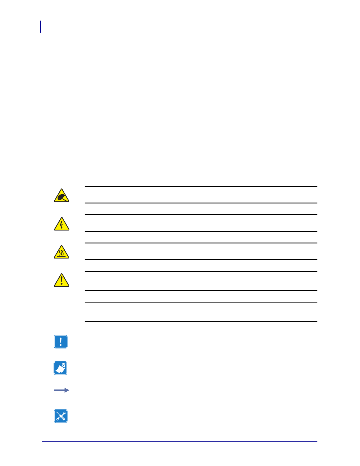
Caution • Warns you of the potential for electrostatic discharge.
Caution • Warns you of a potential electric shock situation.
Caution • Warns you of a situation where excessive heat could cause a burn.
Caution • Advises you that failure to take or avoid a specific action could result in physical
harm to you.
Caution • (No icon) Advises you that failure to take or avoid a specific action could result in
physical harm to the hardware.
Important • Advises you of information that is essential to complete a task.
Note • Indicates neutral or positive information that emphasizes or supplements important
points of the main text.
Example • Provides an example, often a scenario, to better clarify a section of text.
Tools • Tells you what tools you need to complete a given task.
13290L-001 Rev. A S4M User Guide 10/21/05
Page 11
About This Document
Document Conventions
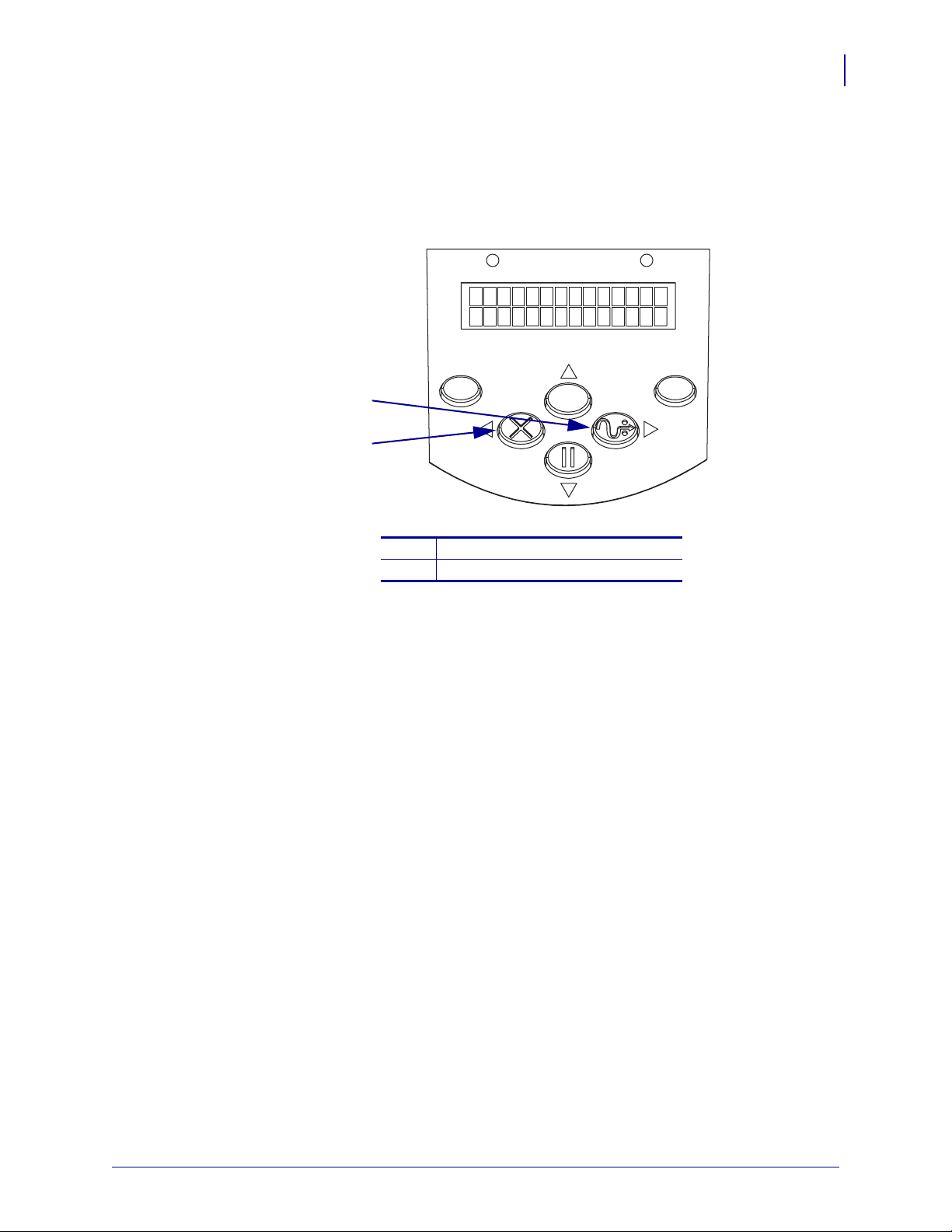
Illustration Callouts Callouts are used when an illustration contains information that needs
to be labeled and described. A table that contains the labels and descriptions follows the
graphic. Figure 1 provides an example.
Figure 1 • Sample Figure with Callouts
POWER ALERT
5
MENU
1
2
FEED button
1
CANCEL button
2
CANCEL FEED
PAUSE
ENTER
10/21/05 S4M User Guide 13290L-001 Rev. A
Page 12

About This Document
6
Document Conventions
Notes • ___________________________________________________________________
__________________________________________________________________________
__________________________________________________________________________
__________________________________________________________________________
__________________________________________________________________________
__________________________________________________________________________
__________________________________________________________________________
__________________________________________________________________________
__________________________________________________________________________
__________________________________________________________________________
13290L-001 Rev. A S4M User Guide 10/21/05
Page 13

1
Introduction
This section shows the operational controls and location of major components used when
loading media and ribbon. Other features of the printer are discussed.
Contents
External View . . . . . . . . . . . . . . . . . . . . . . . . . . . . . . . . . . . . . . . . . . . . . . . . . . . . . . . . . . . 8
Control Panel . . . . . . . . . . . . . . . . . . . . . . . . . . . . . . . . . . . . . . . . . . . . . . . . . . . . . . . . . . . 9
Control Panel LCD . . . . . . . . . . . . . . . . . . . . . . . . . . . . . . . . . . . . . . . . . . . . . . . . . . . . 10
Control Panel Buttons . . . . . . . . . . . . . . . . . . . . . . . . . . . . . . . . . . . . . . . . . . . . . . . . . 10
Control Panel Lights. . . . . . . . . . . . . . . . . . . . . . . . . . . . . . . . . . . . . . . . . . . . . . . . . . . 12
Printer Media Compartment . . . . . . . . . . . . . . . . . . . . . . . . . . . . . . . . . . . . . . . . . . . . . . . 13
Printer Language Modes . . . . . . . . . . . . . . . . . . . . . . . . . . . . . . . . . . . . . . . . . . . . . . . . . 14
Firmware Downloads . . . . . . . . . . . . . . . . . . . . . . . . . . . . . . . . . . . . . . . . . . . . . . . . . . 14
New or Modified Commands . . . . . . . . . . . . . . . . . . . . . . . . . . . . . . . . . . . . . . . . . . . . 14
Additional Printer Language Information . . . . . . . . . . . . . . . . . . . . . . . . . . . . . . . . . . . 14
10/21/05 S4M User Guide 13290L-001 Rev. A
Page 14
Introduction
F
8
External View
External View
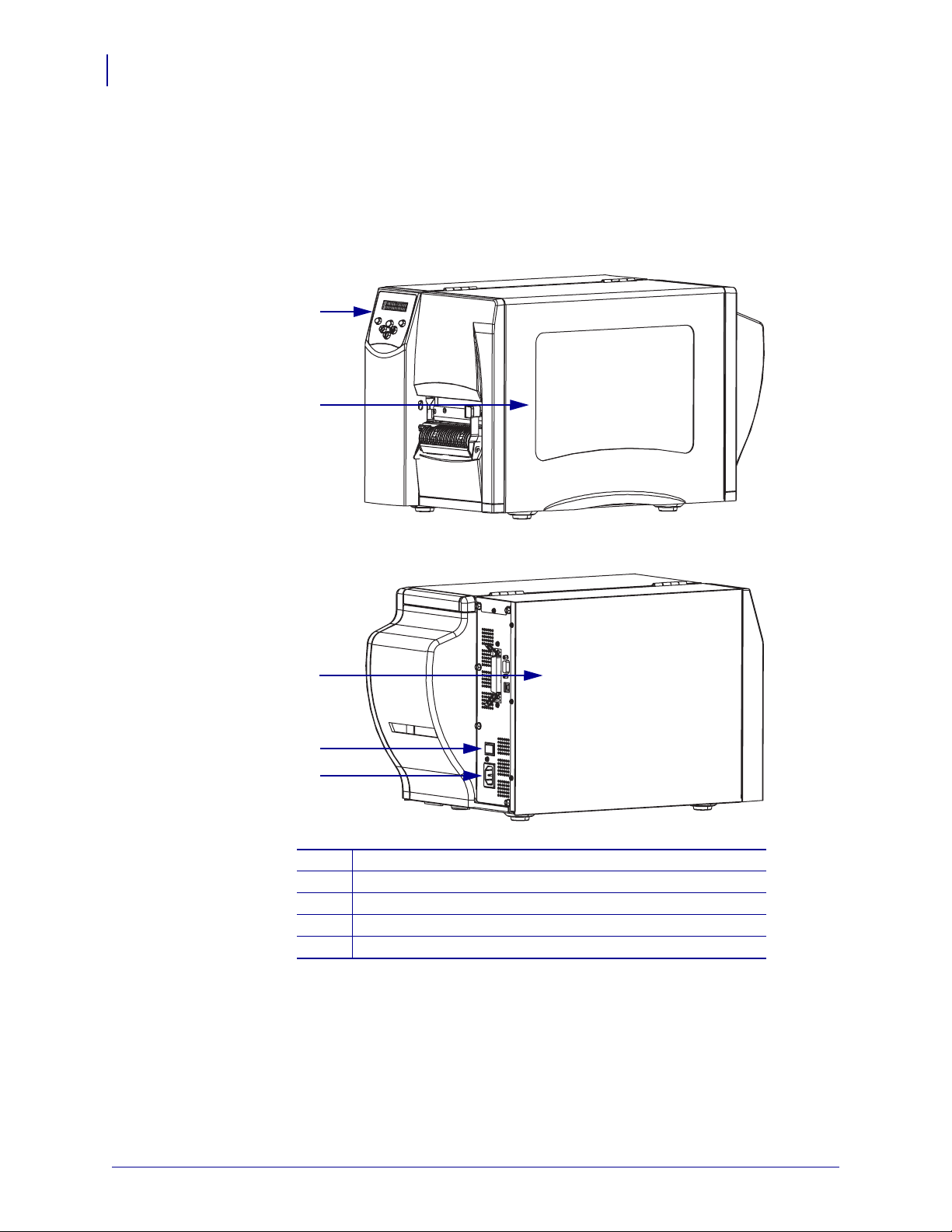
Figure 2 shows the outside of the printer.
Figure 2 • Exterior of Printer
ront
1
2
Rear
3
4
5
Control panel
1
Media door
2
Electronics cover
3
Power switch (O = Off, I = On)
4
AC power connector
5
13290L-001 Rev. A S4M User Guide 10/21/05
Page 15
Control Panel
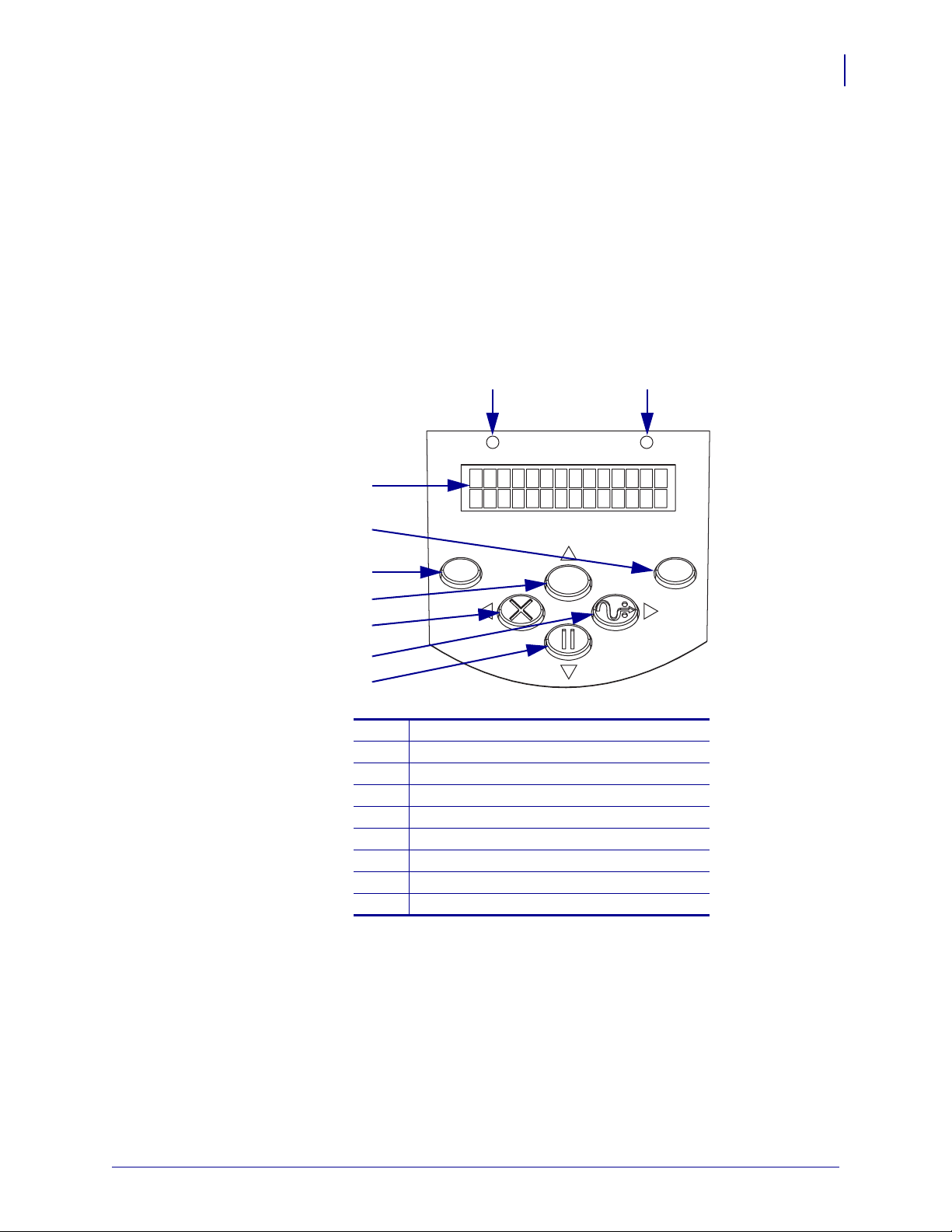
All controls and indicators for the printer are located on the control panel (Figure 3).
•The control panel Liquid Crystal Display (LCD) shows the operating status and printer
parameters.
•The control panel buttons are used to control the printer operations and to set parameters.
•The control panel lights (LEDs) show the printer’s operating status or indicate which
control panel buttons are active.
Figure 3 • Location of Control Panel Buttons and Lights
2 1
POWER ALERT
3
Introduction
Control Panel
9
4
MENU
ENTER
5
6
CANCEL FEED
7
PAUSE
8
9
Alert light
1
Power light
2
LCD
3
ENTER button
4
MENU button
5
Up arrow button
6
CANCEL or Left Arrow button
7
FEED or Right Arrow button
8
PAUSE or Down Arrow button
9
10/21/05 S4M User Guide 13290L-001 Rev. A
Page 16
10
Introduction
Control Panel
Control Panel LCD
The control panel LCD functions differently in different printer modes.
•In Operating mode, the LCD displays the printer’s status, sometimes in conjunction with
a control panel light (see Control Panel Lights on page 12). When the printer is receiving
data, the control panel shows the word
spaces.
•In Pause mode, the printer stops printing temporarily.
•In Setup mode, you can use the control panel LCD to view or modify printer parameters
(see Control Panel LCD Display on page 60).
•In Error mode, the LCD may display an alert or error message (see LCD Error Messages
on page 87).
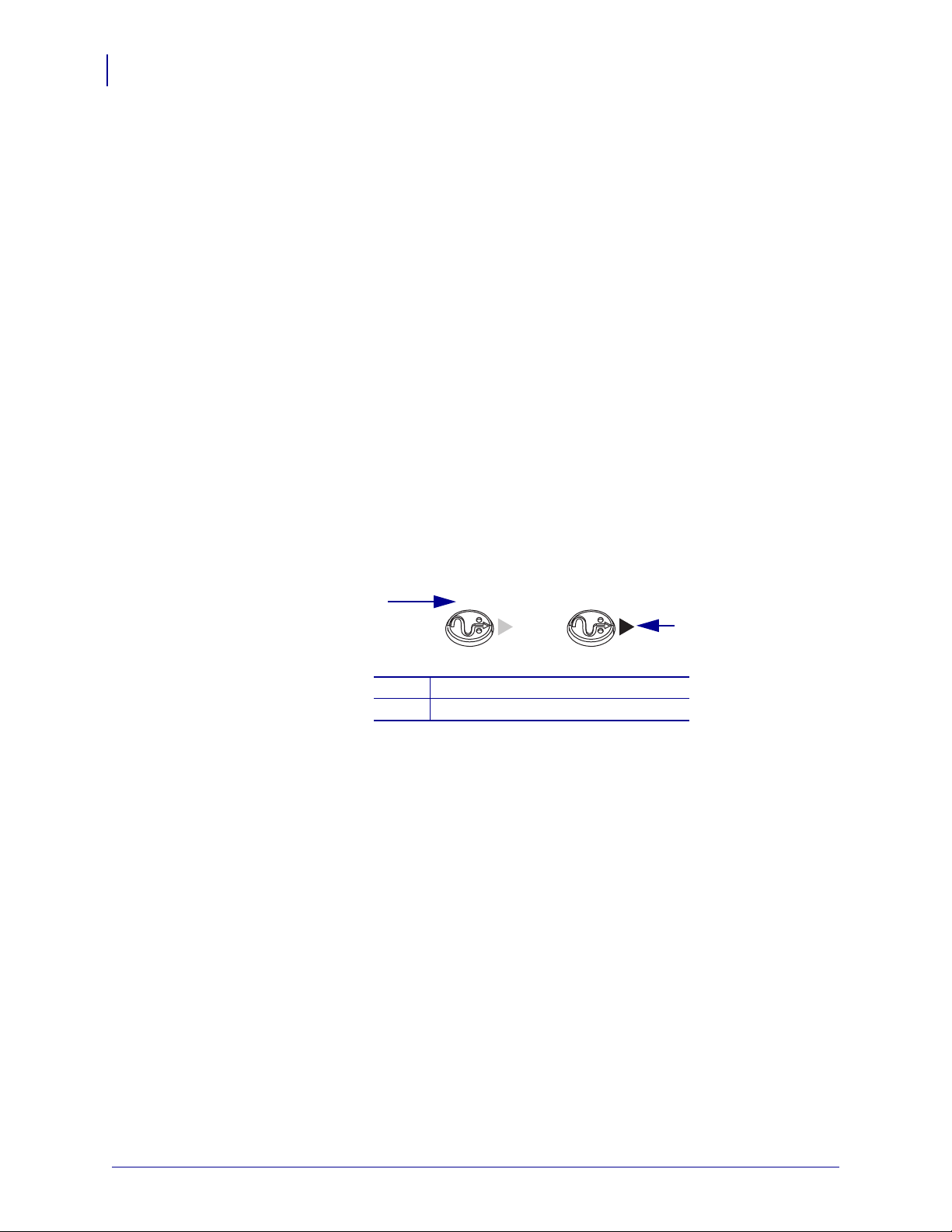
Control Panel Buttons
The printer has six basic control buttons on the control panel. Some of these buttons also
function as navigational keys when the printer is in Setup mode. The current function of a
particular button is determined by which light is illuminated next to it (Figure 4).
DATA and cycles through a series of dots and
Figure 4 • Example of Active Control Panel Buttons
1
1
2
FEED FEED
FEED active
Right arrow active
Table 1 describes the function of each button. The
active when the printer is in normal operating mode.
2
MENU, PAUSE, and FEED buttons are
13290L-001 Rev. A S4M User Guide 10/21/05
Page 17
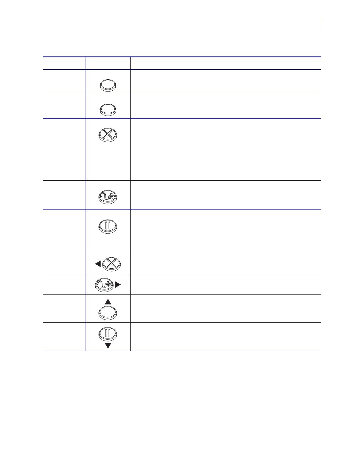
Table 1 • Control Panel Buttons
Introduction
Control Panel
11
Button
MENU
ENTER
CANCEL
FEED
PAU S E
Left Arrow
Appearance
MENU
ENTER
CANCEL
FEED
PAUSE
Function/Description
Enters and exits Setup mode.
If a parameter or option in Setup mode needs to be selected, pressing
ENTER selects the item. This button is active only when necessary.
CANCEL
functions only in Pause mode. Pressing CANCEL once has these
effects:
• Cancels the label format that is currently printing.
• If no label format is printing, the next one to be printed is canceled.
• If no label formats are waiting to be printed,
CANCEL is ignored.
To clear the printer’s entire label format memory, press and hold
CANCEL.
Advances a blank label.
• If the printer is idle or paused, the label is fed immediately.
• If the printer is printing, the label is fed after printing finishes.
Stops and restarts the printing process or removes error messages and
clears the LCD. When the printer is paused, the PAUSE light blinks.
• If the printer is idle, it enters Pause mode immediately.
• If the printer is printing, the label is completed before the printer
pauses.
When in Setup mode, scrolls the LCD to the previous parameter.
Right Arrow
Up Arrow
Down Arrow
When in Setup mode, scrolls the LCD to the next parameter.
When in Setup mode, increases values or scrolls to the next option.
When in Setup mode, decreases values or scrolls to the previous option.
10/21/05 S4M User Guide 13290L-001 Rev. A
Page 18
12
ER
A
Introduction
Control Panel
Control Panel Lights
Table 2 describes lights on the control panel that indicate different printer conditions.
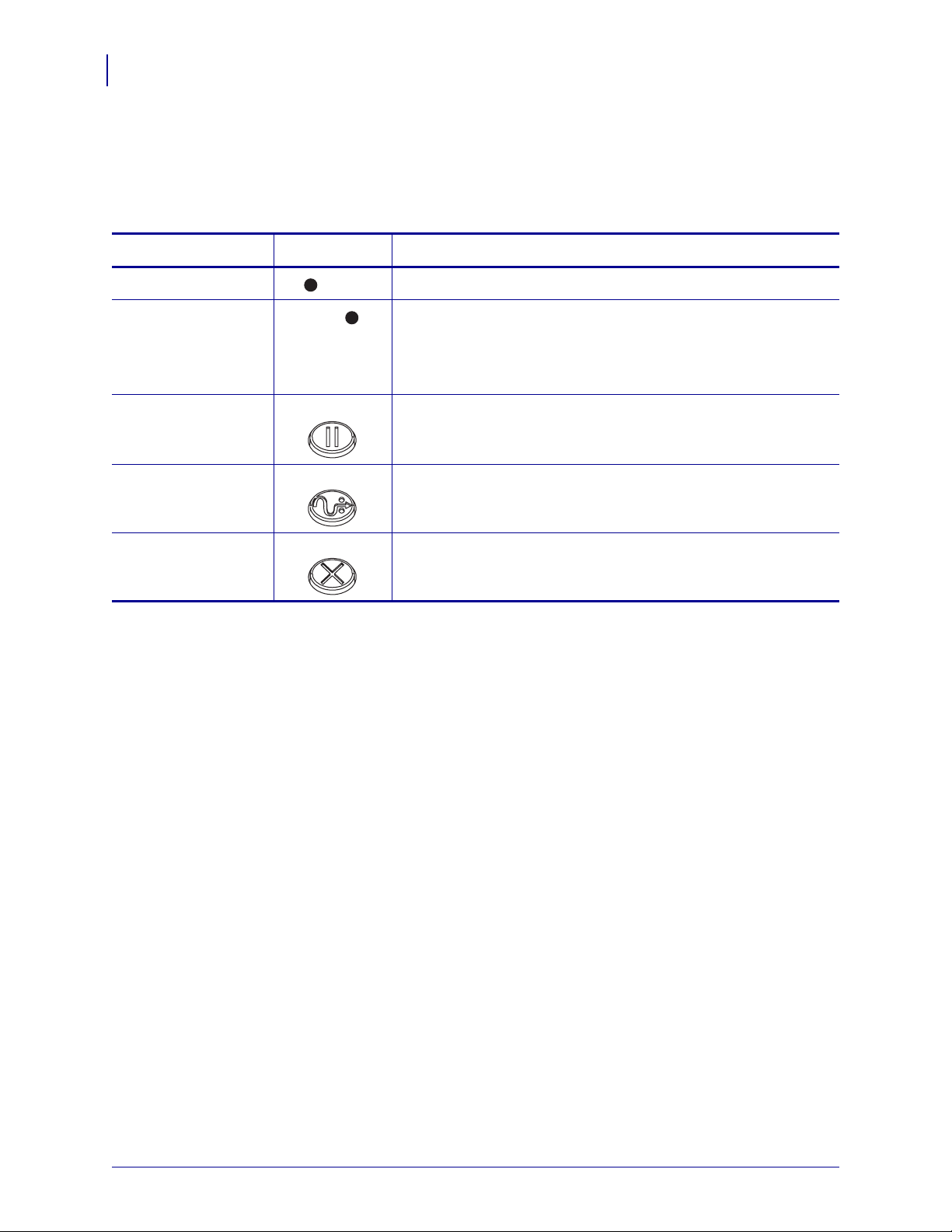
Table 2 • Control Panel Lights
Light
POWER Indicates that the printer is on.
ALERT In an error or alert situation, the ALERT light operates as follows:
Appearance
POW
LERT
Function/Description
• Remains on (solid) when the printer requires operator attention,
such as when the print mechanism is open.
• Flashes when the ribbon or media is out.
PAUSE (part of the
PAU S E button)
FEED (part of the
FEED button)
CANCEL (part of
the
CANCEL button)
PAUSE
FEED
CANCEL
Flashes when the printer is in Pause mode unless the printer enters
Setup mode and the down arrow becomes active.
On during normal printer operation, indicating that the printer can
feed a blank label.
On when canceling a label format is a valid option.
13290L-001 Rev. A S4M User Guide 10/21/05
Page 19
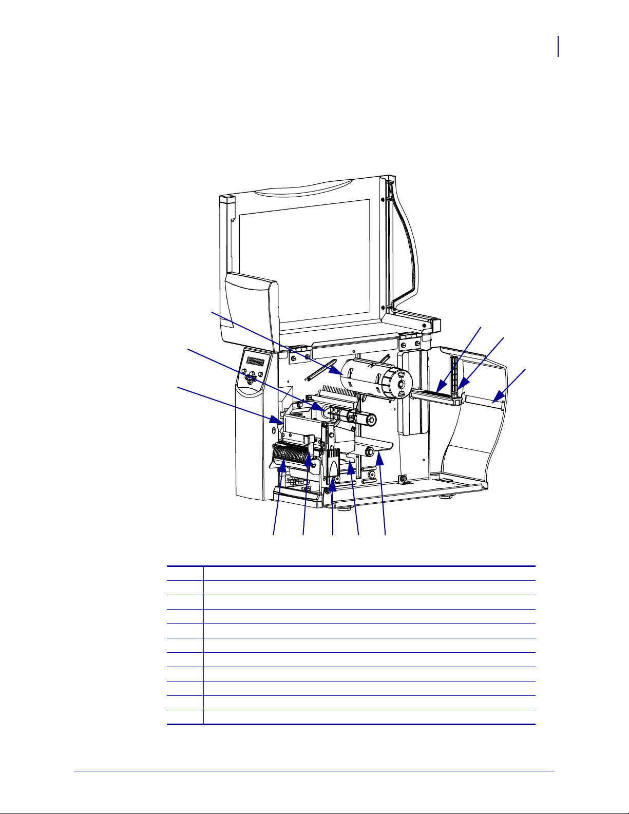
Printer Media Compartment
Figure 5 shows a simplified view of the media compartment of your printer. Depending on
installed options, your printer may look slightly different.
Figure 5 • Media Compartment
3
2
Introduction
Printer Media Compartment
4
5
6
13
1
10 8
11
Printhead assembly
1
Ribbon supply spindle*
2
Ribbon take-up spindle*
3
Media supply hanger
4
Media supply guide
5
Fanfold media slot
6
Dancer assembly
7
Media guide
8
Printhead release latch
9
Peel release lever**
10
Peel assembly**
11
* Present only on printers that have the Thermal Transfer option installed.
** Present only on printers that have the Peel option installed.
79
10/21/05 S4M User Guide 13290L-001 Rev. A
Page 20

Introduction
14
Printer Language Modes
Printer Language Modes
Depending on how your printer was ordered, it came from the factory with firmware that
operates in or allows you to use certain commands for one of the following printer languages:
• Zebra Programming Language (ZPL)
• Eltron Programming Language (EPL)
• Datamax Programming Language (APL-D)
• Intermec Printer Language (APL-I)
Firmware Downloads
You may download S4M firmware to the printer at any time to change from one printer
language to another. For the latest firmware versions and instructions for downloading them,
go to http://www.zebra.com/firmware.
Note • When the printer changes from one printer language to another, error messages may
appear on the LCD, and some control panel lights may activate in error mode. You may
ignore these error messages and lights. When the firmware download is complete, reboot the
printer and load printer defaults to return the printer to Operating mode.
New or Modified Commands
See ZPL II Commands on page 111 for ZPL II commands that changed or that were added
specifically for this printer.
Additional Printer Language Information
The following manuals contain specific information about the different printer language
modes. Copies of these manuals are on the CD that came with your printer and at
http://www.zebra.com/manuals.
• ZPL II Programming Guide, volumes 1 and 2
• EPL2 Programming Guide
• APL-D Reference Guide
• APL-I Reference Guide
13290L-001 Rev. A S4M User Guide 10/21/05
Page 21

2
Printer Setup
This section provides the tasks that you must complete and the issues that you must consider
before you load and configure your printer.
Contents
Before You Begin . . . . . . . . . . . . . . . . . . . . . . . . . . . . . . . . . . . . . . . . . . . . . . . . . . . . . . . 16
Unpack and Inspect the Printer . . . . . . . . . . . . . . . . . . . . . . . . . . . . . . . . . . . . . . . . . . . . 17
Inspect the Printer . . . . . . . . . . . . . . . . . . . . . . . . . . . . . . . . . . . . . . . . . . . . . . . . . . . . 17
Report Shipping Damage. . . . . . . . . . . . . . . . . . . . . . . . . . . . . . . . . . . . . . . . . . . . . . . 17
Store the Printer. . . . . . . . . . . . . . . . . . . . . . . . . . . . . . . . . . . . . . . . . . . . . . . . . . . . . . 17
Shipping . . . . . . . . . . . . . . . . . . . . . . . . . . . . . . . . . . . . . . . . . . . . . . . . . . . . . . . . . . . . 17
Select a Site for the Printer . . . . . . . . . . . . . . . . . . . . . . . . . . . . . . . . . . . . . . . . . . . . . . . 18
Select a Surface. . . . . . . . . . . . . . . . . . . . . . . . . . . . . . . . . . . . . . . . . . . . . . . . . . . . . . 18
Provide Proper Operating Conditions . . . . . . . . . . . . . . . . . . . . . . . . . . . . . . . . . . . . . 18
Allow Proper Space . . . . . . . . . . . . . . . . . . . . . . . . . . . . . . . . . . . . . . . . . . . . . . . . . . . 18
Provide a Data Source. . . . . . . . . . . . . . . . . . . . . . . . . . . . . . . . . . . . . . . . . . . . . . . . . 18
Provide a Power Source . . . . . . . . . . . . . . . . . . . . . . . . . . . . . . . . . . . . . . . . . . . . . . . 18
Connect the Printer to a Power Source . . . . . . . . . . . . . . . . . . . . . . . . . . . . . . . . . . . . . . 19
Power Cord Specifications. . . . . . . . . . . . . . . . . . . . . . . . . . . . . . . . . . . . . . . . . . . . . . 20
Select a Communication Interface . . . . . . . . . . . . . . . . . . . . . . . . . . . . . . . . . . . . . . . . . . 21
Connector Locations . . . . . . . . . . . . . . . . . . . . . . . . . . . . . . . . . . . . . . . . . . . . . . . . . . 21
Types of Connections . . . . . . . . . . . . . . . . . . . . . . . . . . . . . . . . . . . . . . . . . . . . . . . . . 22
Data Cable Requirements . . . . . . . . . . . . . . . . . . . . . . . . . . . . . . . . . . . . . . . . . . . . . . 24
Types of Media. . . . . . . . . . . . . . . . . . . . . . . . . . . . . . . . . . . . . . . . . . . . . . . . . . . . . . . . . 25
Ribbon Overview . . . . . . . . . . . . . . . . . . . . . . . . . . . . . . . . . . . . . . . . . . . . . . . . . . . . . . . 27
When to Use Ribbon . . . . . . . . . . . . . . . . . . . . . . . . . . . . . . . . . . . . . . . . . . . . . . . . . . 27
Coated Side of Ribbon. . . . . . . . . . . . . . . . . . . . . . . . . . . . . . . . . . . . . . . . . . . . . . . . . 27
10/21/05 S4M User Guide 13290L-001 Rev. A
Page 22

Printer Setup
16
Before You Begin
Before You Begin
Review this checklist, and resolve any issues before you set up or use your printer.
Unpack and Inspect the Printer Have you unpacked the printer and inspected it for
Select a Site Have you selected an appropriate location for the printer? If you have not,
Attach a Power Cord Do you have the correct power cord for your printer? If you are
Connect to a Data Source Have you determined how the printer will connect to a
Select Media Do you have the correct media for your application? If you are unsure,
Select Ribbon Do you need to use ribbon, and is the appropriate ribbon available, if
damage? If you have not, see Unpack and Inspect the Printer on page 17.
see Select a Site for the Printer on page 18.
unsure, see Power Cord Specifications on page 20. To attach the power cord and connect
the printer to a power source, see Connect the Printer to a Power Source on page 19.
data source (usually a computer)? For more information, see Select a Communication
Interface on page 21.
see Types of Media on page 25.
needed? If you are unsure, see Ribbon Overview on page 27.
13290L-001 Rev. A S4M User Guide 10/21/05
Page 23

Unpack and Inspect the Printer
When you receive the printer, immediately unpack and inspect it for shipping damage. Save all
packing materials.
Inspect the Printer
Inspect the printer for possible damage incurred during shipment:
• Check all exterior surfaces for damage.
• Raise the media door, and inspect the media compartment for damage to components.
Report Shipping Damage
Important • Zebra Technologies is not responsible for any damage incurred during the
shipment of the equipment and will not repair this damage under warranty
If you discover shipping damage upon inspection:
Printer Setup
Unpack and Inspect the Printer
17
• Immediately notify the shipping company and file a damage report.
• Keep all packaging material for shipping company inspection.
• Notify your authorized Zebra reseller.
Store the Printer
If you are not placing the printer into immediate operation, repackage it using the original
packing materials. You may store the printer under the following conditions:
• Temperature: –40°F to 140°F (–40°C to 60°C)
• Relative humidity: 5% to 85%, non-condensing
Shipping
If you must ship the printer:
• Remove any media or ribbon from the printer to avoid damaging the printer.
• Carefully pack the printer into the original container or a suitable alternate container to
avoid damage during transit. A shipping container can be purchased from Zebra if the
original packaging has been lost or destroyed.
10/21/05 S4M User Guide 13290L-001 Rev. A
Page 24
Printer Setup
18
Select a Site for the Printer
Select a Site for the Printer
Consider the following when selecting an appropriate location for your printer.
Select a Surface
Select a solid, level surface of sufficient size and strength to accommodate the printer and
other equipment (such as a computer), if necessary. The choices include a table, countertop,
desk, or cart.
Provide Proper Operating Conditions
This printer is designed to function in a wide range of environmental and electrical conditions,
including a warehouse or factory floor. For more information on the required conditions, see
General Specifications on page 106.
Table 3 shows the temperature and relative humidity requirements for the printer when it is
operating.
Table 3 • Operating Temperature and Humidity
Mode Temperature Relative Humidity
Thermal Transfer 40° to 104°F (5° to 40°C) 20 to 85% non-condensing
Direct Thermal 32° to 104°F (0° to 40°C) 20 to 85% non-condensing
Allow Proper Space
The printer should have enough space around it for you to be able to open the media door. To
allow for proper ventilation and cooling, leave open space on all sides of the printer.
Caution • Do not place any padding or cushioning material behind or under the printer
because this restricts air flow and could cause the printer to overheat.
Provide a Data Source
If the printer will be located away from the data source, the selected site must provide the
appropriate connections to that data source. For more information on the types of
communication interfaces, see Select a Communication Interface on page 21.
Provide a Power Source
Place the printer within a short distance of a power outlet that is easily accessible.
13290L-001 Rev. A S4M User Guide 10/21/05
Page 25
Connect the Printer to a Power Source
The AC power cord must have a three-prong female connector on one end that plugs into the
mating AC power connector at the rear of the printer. If a power cable was not included with
your printer, refer to Power Cord Specifications on page 20.
Caution • For personnel and equipment safety, always use an approved three-conductor
power cord specific to the region or country intended for installation. This cord must use an
IEC 320 female connector and the appropriate region-specific three-conductor grounded
plug configuration.
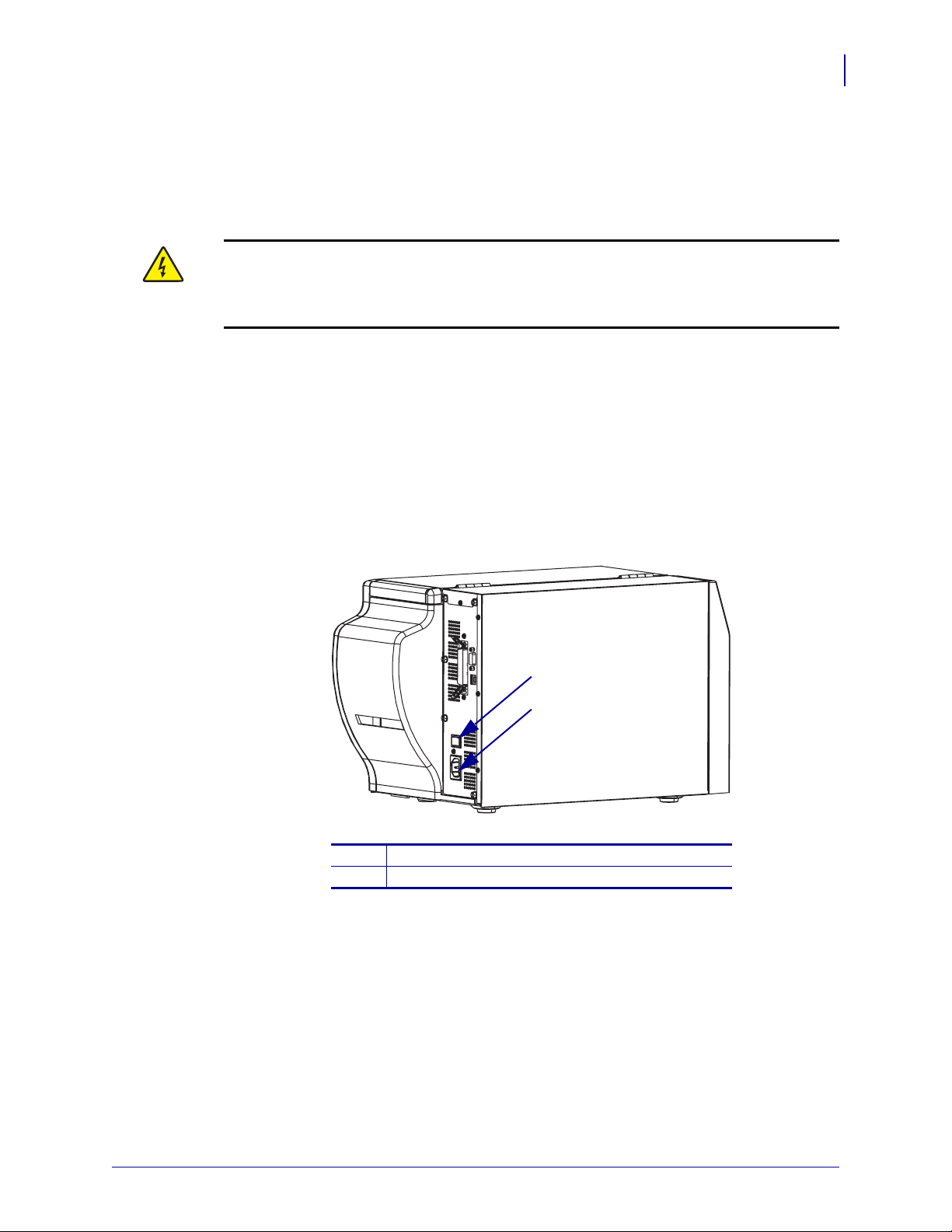
To connect the printer to a power source, complete these steps:
1. Turn the printer power switch to the Off (O) position.
2. Refer to Figure 6. Plug the power cord into the AC power connector on the rear of the
printer.
3. Plug the other end of the power cord into a power outlet near the printer.
Printer Setup
Connect the Printer to a Power Source
19
Figure 6 • Power Connection
Power switch
1
AC power connector
2
1
2
10/21/05 S4M User Guide 13290L-001 Rev. A
Page 26
Printer Setup
20
Connect the Printer to a Power Source
Power Cord Specifications
Caution • For personnel and equipment safety, always use an approved three-conductor
power cord specific to the region or country intended for installation. This cord must use an
IEC 320 female connector and the appropriate region-specific, three-conductor grounded
plug configuration.
Depending on how your printer was ordered, a power cord may or may not be included. If one
is not included or if the one included is not suitable for your requirements, refer to the
following guidelines:
• The overall cord length must be less than 9.8 ft. (3.0 m).
• The cord must be rated for at least 10 A, 250 V.
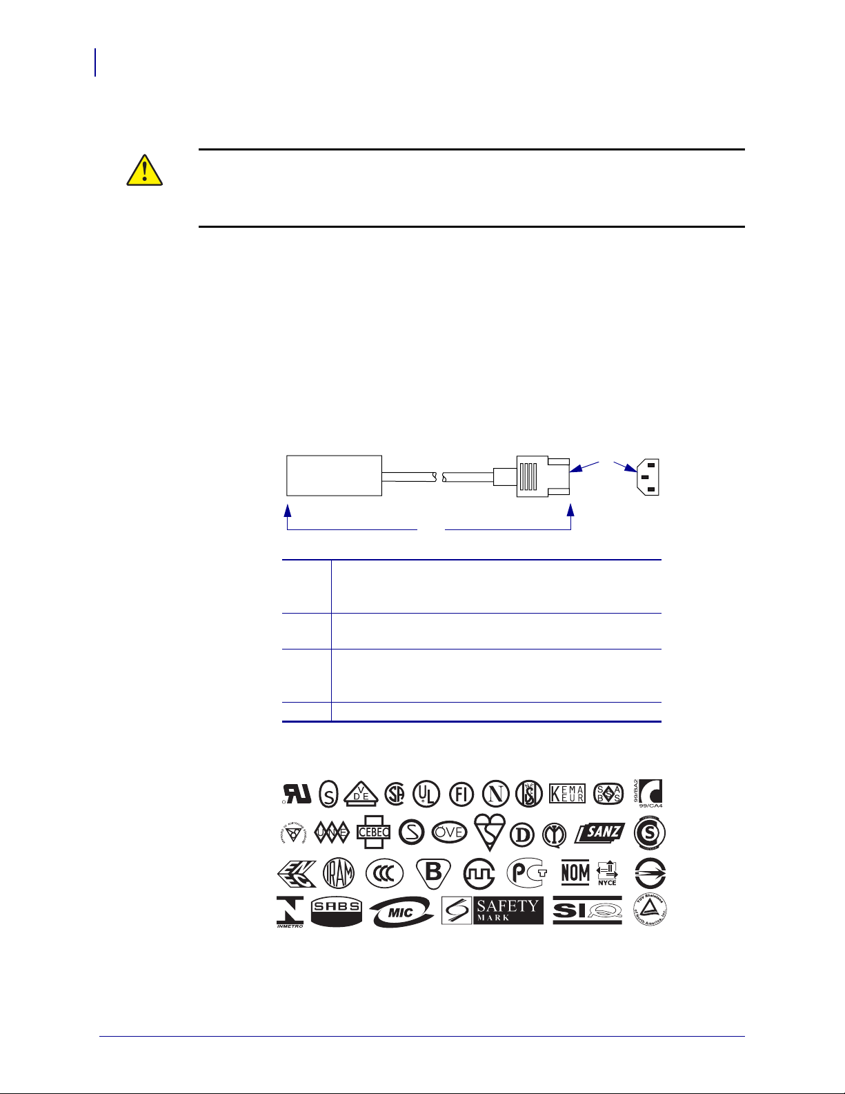
• The chassis ground (earth) must be connected to ensure safety and reduce electromagnetic
interference. The third wire in the power cord grounds the connection (Figure 7).
Figure 7 • Power Cord Specifications
2
1
4
AC power plug for your country—This should bear the
1
3
certification mark of at least one of the known
international safety organizations (Figure 8).
3-conductor HAR cable or other cable approved for
2
your country.
IEC 320 connector—This should bear the certification
3
mark of at least one of the known international safety
organizations (Figure 8).
Length ≤ 9.8 ft (3 m). Rating 10 Amp, 250 VAC.
4
Figure 8 • International Safety Organization Certifications
R
+
13290L-001 Rev. A S4M User Guide 10/21/05
Page 27
Select a Communication Interface
The way that you connect your printer to a data source depends on the communication options
installed in the printer. You may use any available connection to send commands and label
formats from a host computer to the printer.
Caution • Connecting a data communications cable while the power is ON may damage
the printer.
Note • You must supply all interface cables for your application. Refer to Data Cable
Requirements on page 24 for specific cable requirements.
Connector Locations
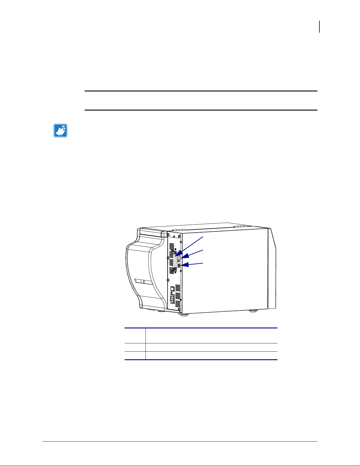
Refer to Figure 9. The printer comes standard with an Electronics Industries Association (EIA)
RS-232 serial interface (DB-9 connector), an IEEE 1284 bidirectional parallel interface
(unless replaced with an optional print server port), and a USB 1.1 port. You may use any of
these interface methods to send commands and label formats from a host to the printer.
Operations
Select a Communication Interface
21
Figure 9 • Cable Connections
1
2
3
Parallel interface connector (not available on units
1
that have an optional print server port)
DB-9 serial interface connector
2
USB 1.1 connector
3
10/21/05 S4M User Guide 13290L-001 Rev. A
Page 28
Operations
22
Select a Communication Interface
Types of Connections
The method of connecting the printer to a data source depends on the communication options
installed in the printer and the host. This section provides basic information about common
interfaces.
When communicating via the serial data port (RS-232), the baud rate, number of data and stop
bits, the parity, and the XON/XOFF or DTR control should be set to match those of the host
computer. See Password Level 3 Parameters on page 65 to configure these parameters. When
communicating via the parallel port or the USB port, the previously mentioned parameters do
not apply.
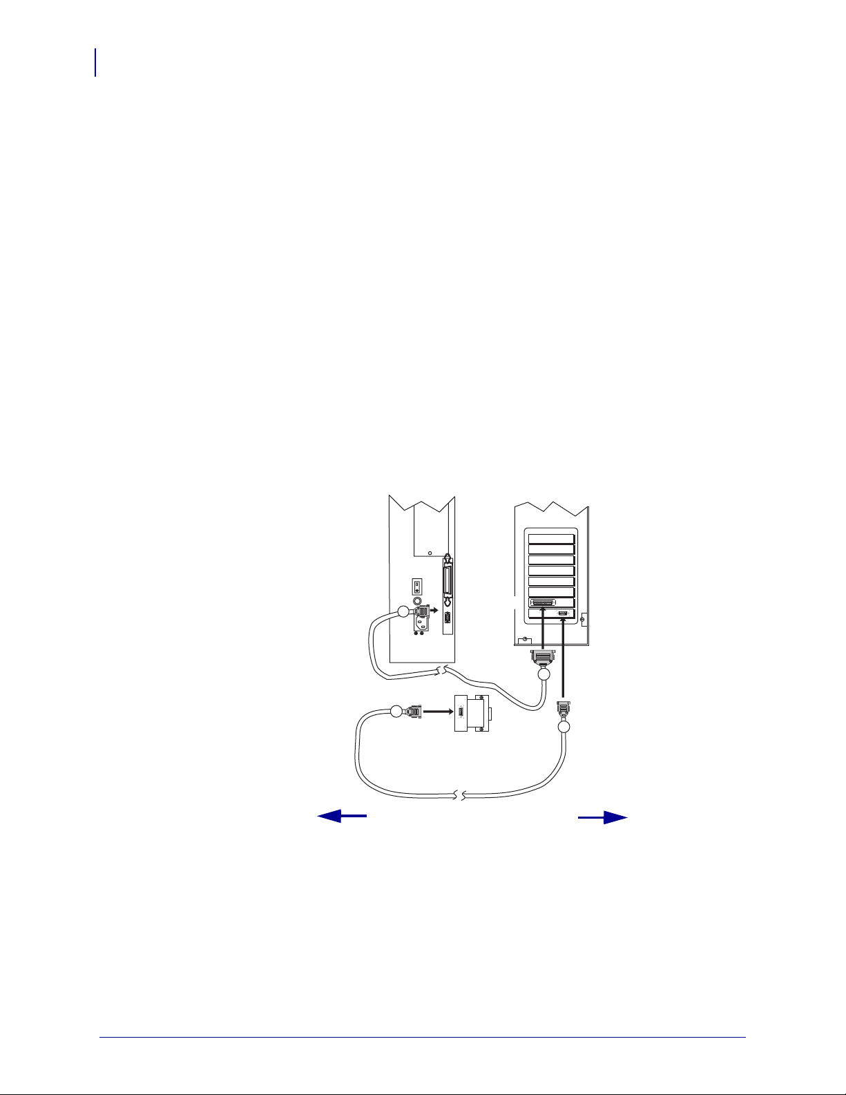
RS-232 Serial A serial communication method consisting of data and control signals;
available as a standard feature on most PCs and other hosts.
• Advantages: Cables and connectors are readily available from computer equipment stores
and suppliers; easy to connect; two-way communication between the host and the printer.
• Disadvantages: Slower than the parallel connection; limited to 50 feet (15.24 m) of cable.
Figure 10 • Communicating Using a Serial Data Port
Printer Computer
9
9
Male
25
Null modem adaptor
(if using a standard
modem cable)
50 ft. (15 m) maximum
9
13290L-001 Rev. A S4M User Guide 10/21/05
Page 29
Operations
Select a Communication Interface
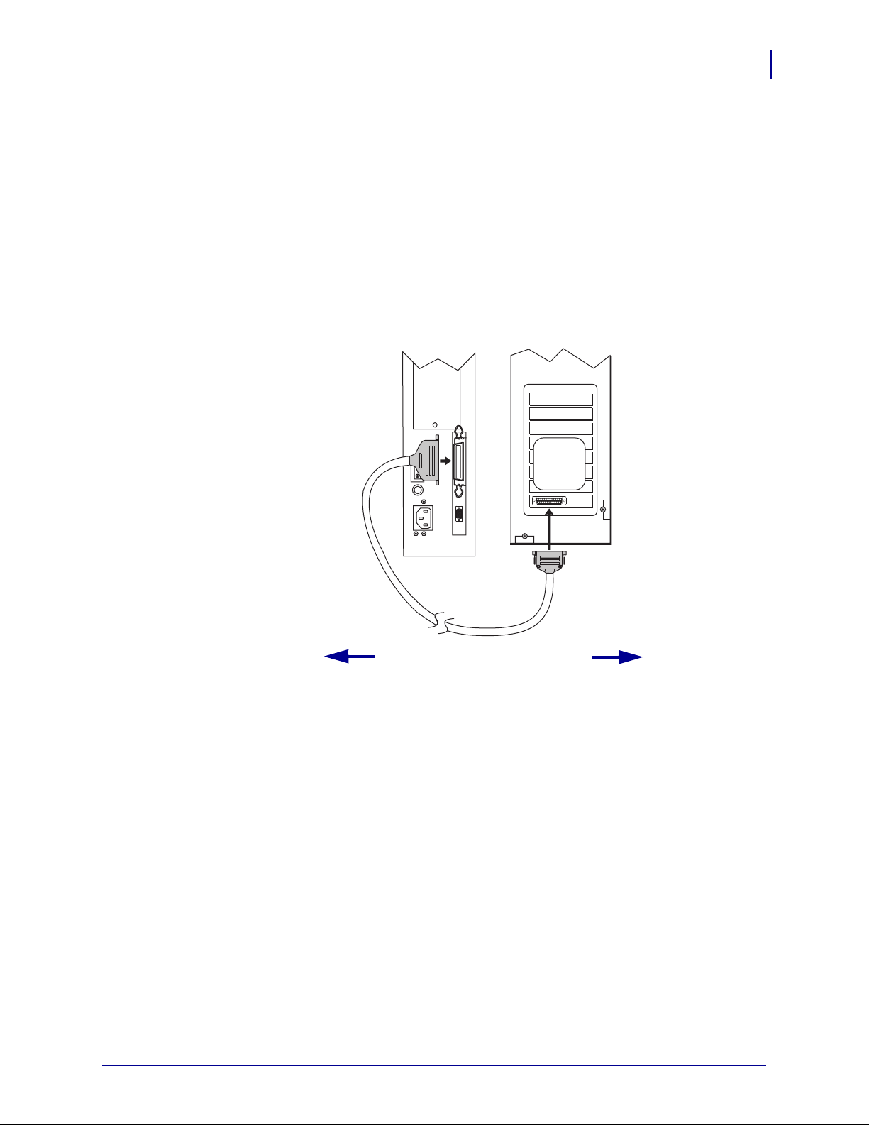
IEEE 1284 Bidirectional Parallel A common communication method available on most
PCs and other hosts.
• Advantages: Fastest of the communication interfaces; cables and connectors are readily
available from computer equipment stores and suppliers; two-way communication
between the host and the printer; easy to connect.
• Disadvantages: Shorter recommended cable length of 6 feet (1.83 m) with a maximum of
length 10 ft (3 m); many computers are equipped with only one parallel port, allowing
only one IEEE 1284 bidirectional device to be connected at a time.
Figure 11 • Communicating Using a Parallel Port
Printer Computer
36-pin
male
23
25-pin
male
10 ft. (3 m) maximum
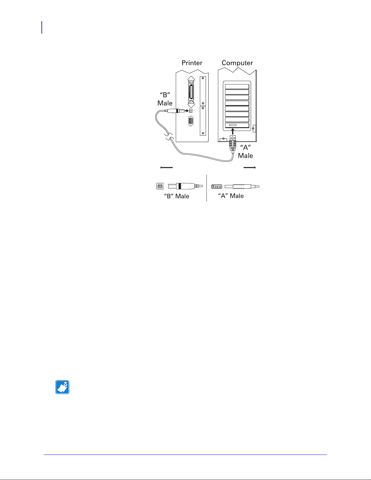
USB 1.1 Port Communicating using the USB port (see Figure 12) does not require special
settings.
• Advantages: Many computers are equipped with more than one USB port, allowing
multiple USB devices to be connected at one time; cables and connectors are readily
available from computer equipment stores and suppliers; two-way communication
between the host and the printer; easy to connect.
• Disadvantages: Cable length limited to 16.4 ft (5 m).
10/21/05 S4M User Guide 13290L-001 Rev. A
Page 30
Operations
24
Select a Communication Interface
Figure 12 • Communicating Using a USB Port
=
16.4 ft (5 m) maximum
Optional Print Servers Ethernet-based print severs also are available to connect your
printer to a data source. Both wired and wireless options are available.
• With the ZebraNet Wireless Print Server board installed, a wireless PCMCIA card can be
used to communicate with a network. For more information on this option, see the
ZebraNet Wireless Print Server User Guide.
• ZebraNet 10/100 Print Server (10/100 PS). For more information on 10/100 PS, see the
ZebraNet 10/100 Print Server User and Reference Guide.
Data Cable Requirements
Data cables must be fully shielded and fitted with metal or metallized connector shells.
Shielded cables and connectors are required to prevent radiation and reception of electrical
noise.
To minimize electrical noise pickup in the cable:
• Keep data cables as short as possible.
• Do not bundle the data cables tightly with the power cords.
• Do not tie the data cables to power wire conduits.
Note • Zebra printers comply with FCC Rules and Regulations, Part 15 for Class B
Equipment using fully shielded, 6.5 ft (2 m) data cables. Use of unshielded cables may
increase radiation above the Class B limits.
13290L-001 Rev. A S4M User Guide 10/21/05
Page 31

Types of Media
The printer can use various types of media (Table 4). Zebra strongly recommends the use of
Zebra-brand supplies for continuous high-quality printing. A wide range of paper,
polypropylene, polyester, and vinyl stock has been specifically engineered to enhance the
printing capabilities of the printer and to ensure against premature printhead wear.
Table 4 • Types of Media
Media Type How It Looks Description
Printer Setup
Types of Media
25
Non-Continuous
Roll Media
Roll media is wound on a core that can be 1 in. to
3 in. (25 to 76 mm) in diameter. Labels have
adhesive backing that sticks them to a liner, and they
are separated by gaps, holes, notches, or black marks.
Tags are separated by perforations.
Figure 13 • Non-Continuous Web Media
Figure 14 • Black Mark Media
Figure 15 • Tag Stock
10/21/05 S4M User Guide 13290L-001 Rev. A
Page 32
Printer Setup
26
Types of Media
Table 4 • Types of Media (Continued)
Media Type How It Looks Description
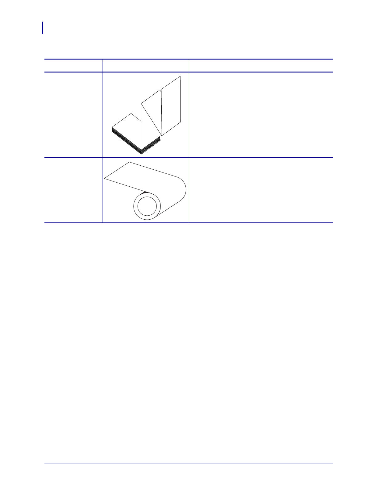
Non-Continuous
Fanfold Media
Continuous
Roll Media
Fanfold media is folded in a zigzag pattern. Fanfold
media can the same label divisions as non-continuous
roll media. The divisions would fall on or near the
folds.
Continuous media is wound on a core and is without
gaps, holes, notches, or black marks. This allows the
image to be printed anywhere on the label. With
continuous media, use the transmissive sensor so the
printer can detect when the media runs out.
13290L-001 Rev. A S4M User Guide 10/21/05
Page 33
Ribbon Overview
Note • This section applies only to printers that have the Thermal Transfer option installed.
Ribbon is a thin film that is coated on one side with wax, resin, or wax resin, which is
transferred to the media during the thermal transfer process. The media determines whether
you need to use ribbon and how wide the ribbon must be.
When ribbon is used, it must be as wide as or wider than the media being used. If the ribbon is
narrower than the media, areas of the printhead are unprotected and subject to premature wear.
When to Use Ribbon
Thermal transfer media requires ribbon for printing while direct thermal media does not.
To determine if ribbon must be used with a particular media, perform a media scratch test.
To perform a label scratch test, complete these steps:
Print Engine Setup
Ribbon Overview
27
1. Scratch the print surface of the media rapidly with your fingernail.
2. Did a black mark appear on the media?
If a black mark... Then the media is...
Does not appear on the media Thermal transfer. A ribbon is required.
Appears on the media Direct thermal. No ribbon is required.
Coated Side of Ribbon
Ribbon can be wound with the coated side on the inside or outside (Figure 16). This printer
can only use ribbon that is coated on the outside. If you are unsure which side of a particular
roll of ribbon is coated, perform an adhesive test or a ribbon scratch test to determine which
side is coated.
Figure 16 • Ribbon Coated on Outside or Inside
Outside Inside
10/21/05 S4M User Guide 13290L-001 Rev. A
Page 34

Print Engine Setup
28
Ribbon Overview
Adhesive Test
If you have labels available, perform the adhesive test to determine which side of a ribbon is
coated. This method works well for ribbon that is already installed.
To perform an adhesive test, complete these steps:
1. Peel a label from its liner.
2. Press a corner of the sticky side of the label to the outer surface of the roll of ribbon.
3. Peel the label off of the ribbon.
4. Observe the results. Did flakes or particles of ink from the ribbon adhere to the label?
If ink from the
ribbon...
Then...
Adhered to the label The ribbon is coated on the outer surface.
Did not adhere to
the label
The ribbon is coated on the inner surface and cannot be
used in this printer. To verify this, repeat the test on the
other surface of the roll of ribbon.
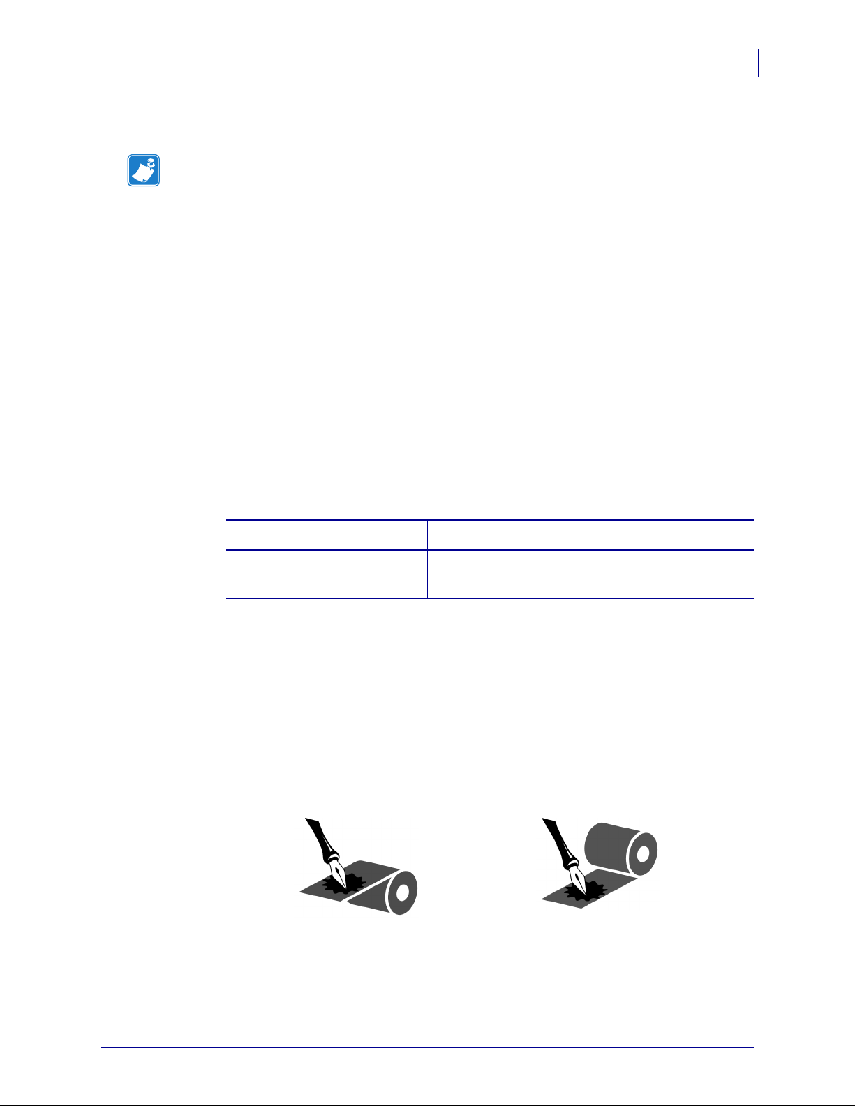
Ribbon Scratch Test
Perform the ribbon scratch test when labels are unavailable.
To perform a ribbon scratch test, complete these steps:
1. Unroll a short length of ribbon.
2. Place the unrolled section of ribbon on a piece of paper with the outer surface of the
ribbon in contact with the paper.
3. Scratch the inner surface of the unrolled ribbon with your fingernail.
4. Lift the ribbon from the paper.
5. Observe the results. Did the ribbon leave a mark on the paper?
If the ribbon... Then...
Left a mark on the paper The ribbon is coated on the outer surface.
Did not leave a mark on
the paper
The ribbon is coated on the inner surface and cannot be
used in this printer. To verify this, repeat the test on the
other surface of the roll of ribbon.
13290L-001 Rev. A S4M User Guide 10/21/05
Page 35

3
Operations
This section provides the procedures for loading and calibrating the printer.
Note • Complete the tasks and resolve the issues in Printer Setup on page 15 before
operating the printer.
Contents
Media Loading Overview . . . . . . . . . . . . . . . . . . . . . . . . . . . . . . . . . . . . . . . . . . . . . . . . . 30
Print Modes . . . . . . . . . . . . . . . . . . . . . . . . . . . . . . . . . . . . . . . . . . . . . . . . . . . . . . . . . 30
Starting a Roll of Media . . . . . . . . . . . . . . . . . . . . . . . . . . . . . . . . . . . . . . . . . . . . . . . . 30
Inserting Media into the Printer . . . . . . . . . . . . . . . . . . . . . . . . . . . . . . . . . . . . . . . . . . 31
Load Media in Tear-Off Mode. . . . . . . . . . . . . . . . . . . . . . . . . . . . . . . . . . . . . . . . . . . . . . 33
Load Media in Peel-Off Mode . . . . . . . . . . . . . . . . . . . . . . . . . . . . . . . . . . . . . . . . . . . . . 36
Load Ribbon. . . . . . . . . . . . . . . . . . . . . . . . . . . . . . . . . . . . . . . . . . . . . . . . . . . . . . . . . . . 41
Remove the Ribbon . . . . . . . . . . . . . . . . . . . . . . . . . . . . . . . . . . . . . . . . . . . . . . . . . . . 44
Calibrate the Printer . . . . . . . . . . . . . . . . . . . . . . . . . . . . . . . . . . . . . . . . . . . . . . . . . . . . . 46
Auto Calibration . . . . . . . . . . . . . . . . . . . . . . . . . . . . . . . . . . . . . . . . . . . . . . . . . . . . . . 46
Manual Calibration . . . . . . . . . . . . . . . . . . . . . . . . . . . . . . . . . . . . . . . . . . . . . . . . . . . . 46
Position the Media Sensors . . . . . . . . . . . . . . . . . . . . . . . . . . . . . . . . . . . . . . . . . . . . . . . 47
Select the Transmissive Sensor. . . . . . . . . . . . . . . . . . . . . . . . . . . . . . . . . . . . . . . . . . 47
Adjust the Reflective Sensor . . . . . . . . . . . . . . . . . . . . . . . . . . . . . . . . . . . . . . . . . . . . 47
Adjust Printhead Pressure . . . . . . . . . . . . . . . . . . . . . . . . . . . . . . . . . . . . . . . . . . . . . . . . 49
10/21/05 S4M User Guide 13290L-001 Rev. A
Page 36
Operations
30
Media Loading Overview
Media Loading Overview
The printer can print on roll or fanfold media and use different print modes for label removal.
Print Modes
The methods for loading media for each print mode follow in this section. Use a print mode
that matches the media being used and the printer options available (Table 5). For more
information on the types of media, see Types of Media on page 25.
Mode When to Use Printer Action
Table 5 • Print Mode Options
Tear-Off (default setting) Use for most applications.
Peel-Off Use only if printer has the
Starting a Roll of Media
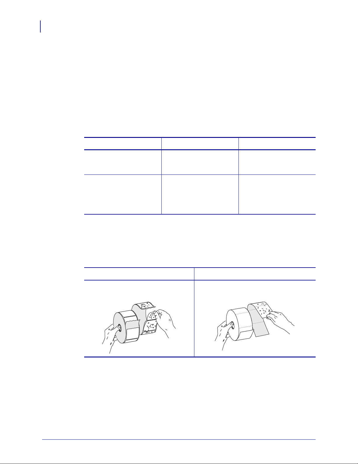
Exposed media may become dirty when handled or stored. To start a roll of media, remove and
discard one full revolution of labels or tags and any liner.
Labels Tag Stock
Remove all labels that are held by
adhesives or tape.
See Load Media in Tear-Off
Mode on page 33.
Peel-Off option. See Load
Media in Peel-Off Mode
on page 36.
Detach all exposed tags.
Each label or strip of labels
can be torn off after printing.
The liner is peeled away
from the label during
printing. When the printed
label is removed, the next
label prints.
13290L-001 Rev. A S4M User Guide 10/21/05
Page 37
Inserting Media into the Printer
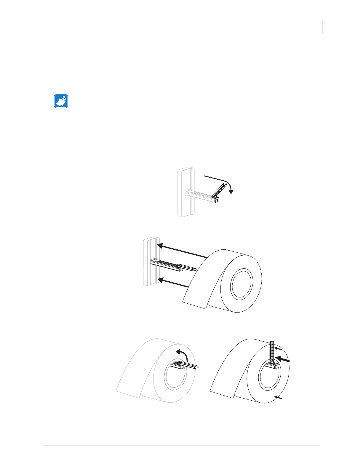
This section shows how to insert roll or fanfold media into the printer. Fanfold media is loaded
the same way as roll media, except the media is stored outside of the printer. See Figure 17
on page 33 for an illustration.
Note • Depending on the media hanger that came with your printer, the size of the media
core that can be used may vary. See Media Specifications on page 109 for the core sizes that
your printer supports.
Roll Media
To insert roll media, complete these steps:
1. Flip down the media supply guide.
Operations
Media Loading Overview
31
2. Place the roll of media on the media supply hanger. Push the roll as far back as it will go.
3. Flip up the media supply guide, and then slide it in until it touches, but does not restrict,
the edge of the roll.
4. Continue with the media loading procedure for the desired print mode.
10/21/05 S4M User Guide 13290L-001 Rev. A
Page 38
Operations
32
Media Loading Overview
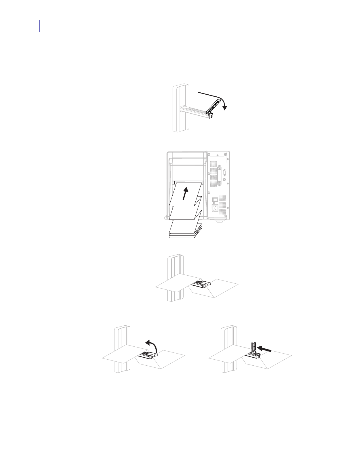
Fanfold Media
To insert fanfold media, complete these steps:
1. Flip down the media supply guide.
2. Thread the fanfold media through the fanfold media slot on the rear of the printer.
3. Drape the media over the media supply hanger.
4. Flip up the media supply guide, and then slide it in until it touches, but does not restrict,
the edge of the media.
5. Continue with the media loading procedure for the desired print mode.
13290L-001 Rev. A S4M User Guide 10/21/05
Page 39

Load Media in Tear-Off Mode
Tear-Off is the default mode. Figure 17 shows roll and fanfold media loaded in Tear-Off mode.
Figure 17 • Tear-Off Mode
1
Roll Media
Operations
Load Media in Tear-Off Mode
3
2
5678
4
33
2
1
Fanfold Media
5678
Printhead assembly
1
Transmissive sensor
2
Media supply guide
3
Media supply hanger
4
Dancer
5
Media guide
6
Printhead release latch
7
Printed label
8
To load media in Tear-Off Mode, complete these steps:
1. Set the printer to Tear-Off mode. See Select the Label Removal Method on page 63 for
instructions.
3
4
2. Insert the media in the printer. See Inserting Media into the Printer on page 31 for
instructions.
10/21/05 S4M User Guide 13290L-001 Rev. A
Page 40
Operations
34
Load Media in Tear-Off Mode
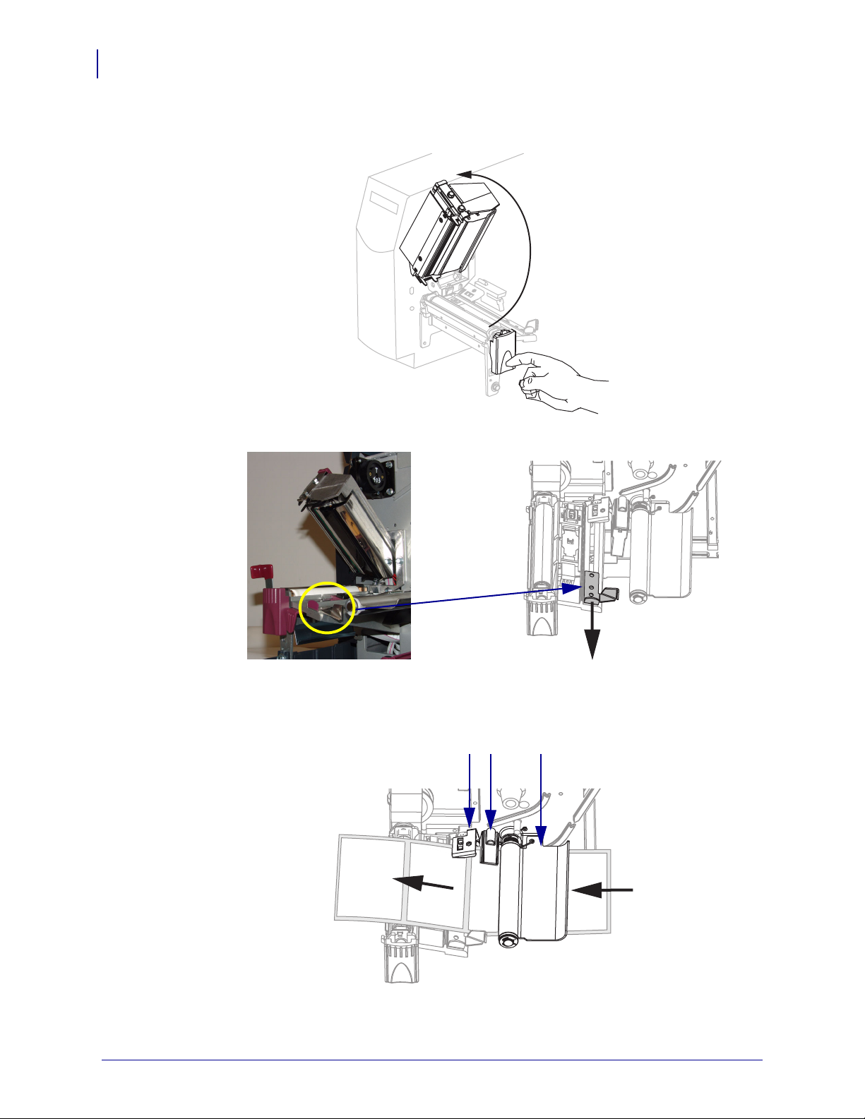
3. Press the printhead release latch to open the printhead assembly. Lift the printhead until it
latches open.
4. Slide out the media guide.
5. Feed the media under the dancer assembly (1), through the slot in the transmissive
sensor (
2), and under the ribbon sensor (3). Push the media to the back of the transmissive
sensor.
123
13290L-001 Rev. A S4M User Guide 10/21/05
Page 41

Load Media in Tear-Off Mode
6. Slide in the media guide until it just touches the edge of the media.
7. Close the printhead assembly.
Operations
35
8. If the printer is paused (the PAUSE light is blinking), press PAU SE to enable printing.
10/21/05 S4M User Guide 13290L-001 Rev. A
Page 42

Operations
36
Load Media in Peel-Off Mode
Load Media in Peel-Off Mode
This section applies only if the Peel-Off option is installed (Figure 18).
Figure 18 • Peel-Off Mode
Peel lever
1
Tear-off/peel-off bar
2
Printhead assembly
3
Transmissive sensor
4
Media supply guide
5
Media supply hanger
6
Liner take-up spindle
7
12
11
4
3
1
2
13
8
9
10
11
12
13
5
6
8910
Dancer
Media guide
Printhead release latch
Peel assembly
Label
Label liner
To load media in Peel-Off mode, complete these steps:
1. Set the printer to Peel-Off mode. See Select the Label Removal Method on page 63 for
instructions.
2. Insert the media in the printer. See Inserting Media into the Printer on page 31 for
instructions.
13290L-001 Rev. A S4M User Guide 10/21/05
Page 43

Load Media in Peel-Off Mode
3. Press the printhead release latch to open the printhead assembly.
4. Lift the printhead until it latches open.
5. Slide out the media guide.
Operations
37
10/21/05 S4M User Guide 13290L-001 Rev. A
Page 44

Operations
38
Load Media in Peel-Off Mode
6. Feed the media under the dancer assembly, through the slot in the transmissive sensor, and
under the ribbon sensor. Push the media to the back of the transmissive sensor.
123
Dancer assembly
1
Transmissive sensor
2
Ribbon sensor
3
7. Push down the peel-off mechanism release lever to open the peel assembly.
8. Pull approximately 18 in. (500 mm) of media through the front of the printer.
9. Remove the exposed labels so that only the liner remains.
13290L-001 Rev. A S4M User Guide 10/21/05
Page 45

Operations
Load Media in Peel-Off Mode
10. Feed the liner over the tear-off/peel-off bar and behind the peel assembly. Make sure that
the end of the liner falls outside of the printer.
1
39
2
Tear-off/peel-off bar
1
Peel assembly
2
11. Slide in the media guide until it just touches the edge of the media.
10/21/05 S4M User Guide 13290L-001 Rev. A
Page 46

Operations
40
Load Media in Peel-Off Mode
12. Close the printhead assembly.
13. Close the peel assembly using the peel-off mechanism release lever.
14. If the printer is paused (the PAUSE light is blinking), press PAU SE to enable printing.
Peeling starts automatically.
13290L-001 Rev. A S4M User Guide 10/21/05
Page 47

Load Ribbon
Note • This section applies only to printers that have the Thermal Transfer option installed.
The ribbon supply spindle in your printer is a dual-tension variety. Most applications require
the spindle to be in the normal position. The low tension position is recommended only when a
narrow ribbon is used or if normal tension hampers the ribbon movement.
Note • Always use ribbon that is wider than the media to protect the printhead from wear.
For direct thermal printing, do not load ribbon in the printer.
Figure 19 • Ribbon Path
Operations
Load Ribbon
41
3
2
1
Printhead assembly
1
Ribbon supply spindle
2
Ribbon take-up spindle
3
Tension blades
4
4
10/21/05 S4M User Guide 13290L-001 Rev. A
Page 48
42
Operations
Load Ribbon
To load ribbon, complete these steps:
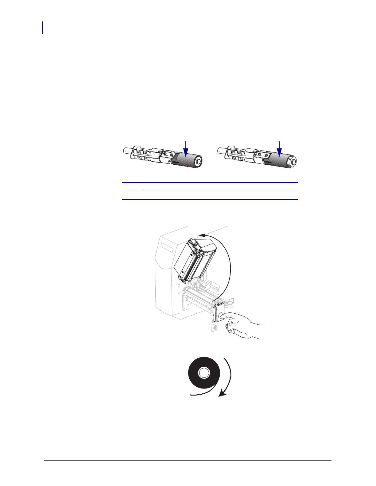
1. Set the ribbon supply spindle for normal or low tension.
• To place the ribbon supply spindle in the normal position, firmly pull out the spindle
end cap until it extends and clicks in place, as shown in Figure 20.
• To place the ribbon supply spindle in the low-tension position, firmly push in the end
cap until it retracts and clicks in place, as shown in Figure 20.
Figure 20 • Ribbon Spindle—Normal and Low Tension
1 2
Normal Position (Spindle End Cap Extended)
1
Low-Tension Position (Spindle End Cap Retracted)
2
2. Press the printhead release latch to open the printhead assembly. Lift the printhead until it
latches open.
3. Orient the ribbon with the loose end unrolling clockwise.
13290L-001 Rev. A S4M User Guide 10/21/05
Page 49
Operations
Load Ribbon
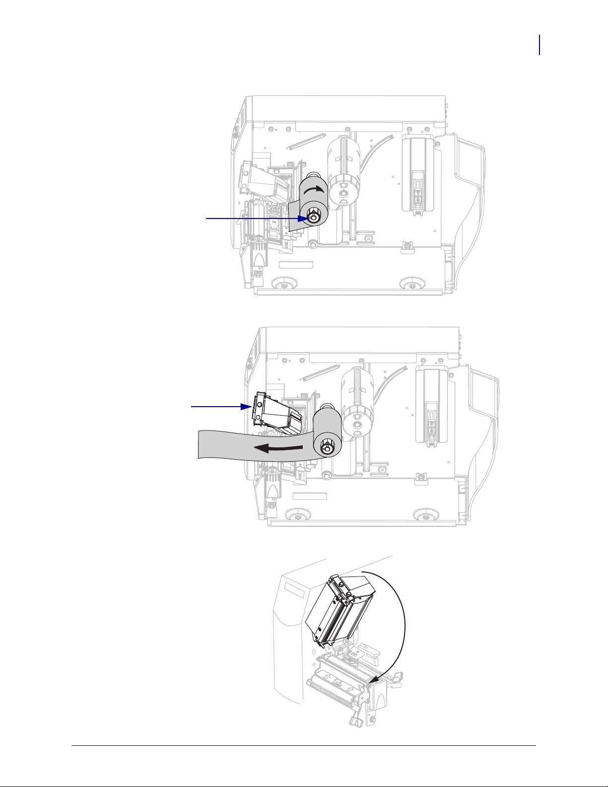
4. Place the ribbon roll onto the ribbon supply spindle (1) and push it all the way back.
1
5. Pull the end of the ribbon under the printhead assembly (2) and out the front of the printer.
43
2
6. Close the printhead assembly.
10/21/05 S4M User Guide 13290L-001 Rev. A
Page 50
44
Operations
Load Ribbon
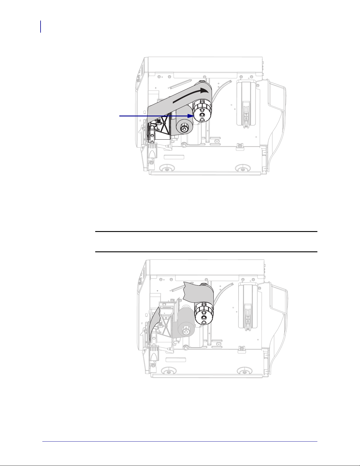
7. Wind the ribbon clockwise onto the ribbon take-up spindle (3).
3
Remove the Ribbon
To remove used ribbon, complete these steps:
1. If the ribbon has not run out, cut or break it before the ribbon take-up spindle.
Caution •
damage the spindle.
Do not cut the ribbon directly on the ribbon take-up spindle. Doing so may
13290L-001 Rev. A S4M User Guide 10/21/05
Page 51
Operations
Load Ribbon
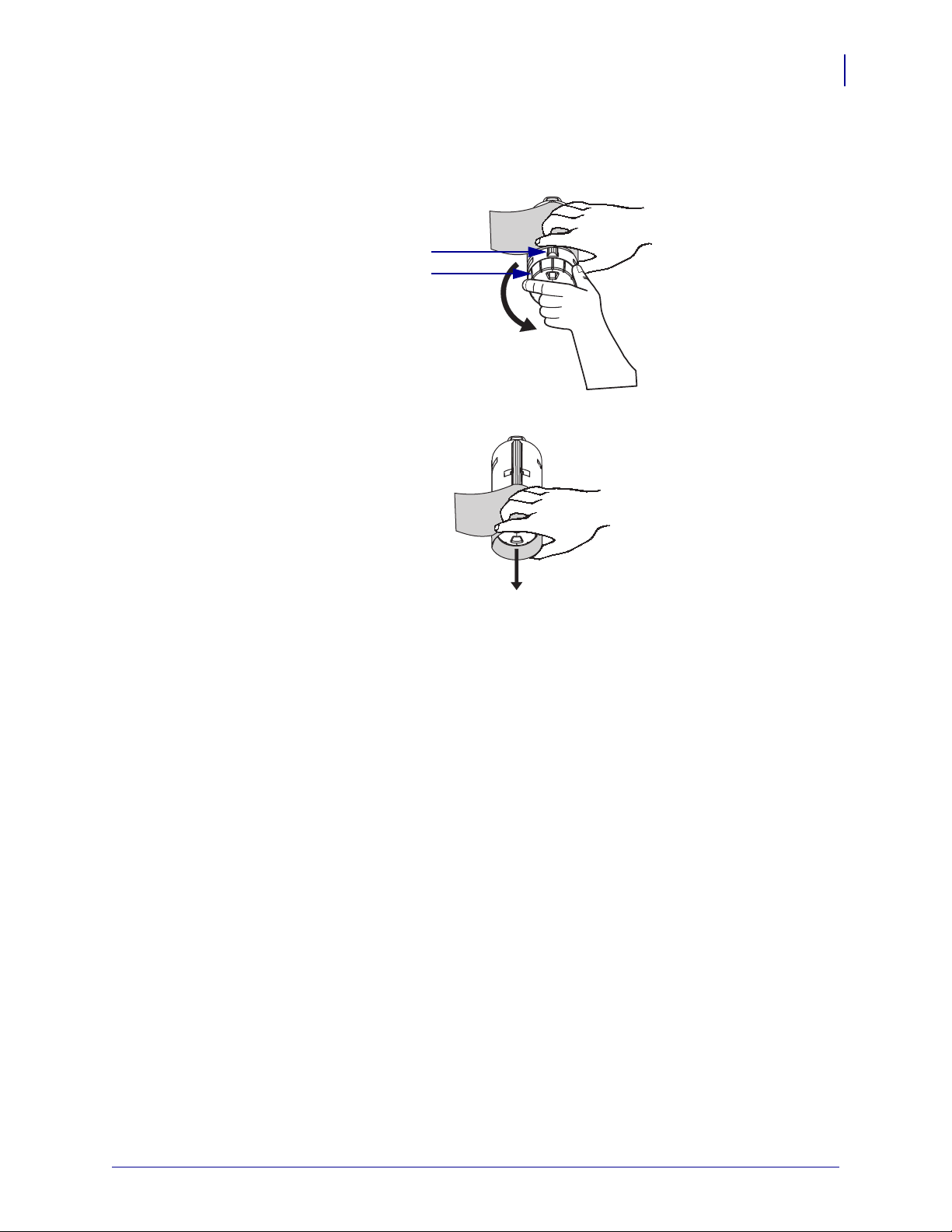
2. Squeeze the ribbon against the ribbon take-up spindle tension blades (1). At the same
time, turn the ribbon take-up spindle release knob counterclockwise (
2).
The tension blades collapse into the ribbon take-up spindle, loosening the ribbon.
1
2
3. Slide the ribbon off of the ribbon take-up spindle.
45
10/21/05 S4M User Guide 13290L-001 Rev. A
Page 52

Operations
46
Calibrate the Printer
Calibrate the Printer
Auto Calibration
By default, the printer automatically calibrates on power up or when the printhead is closed.
During auto calibration, the printer determines the label length and sensor settings.
The results of the auto calibration are stored in the printer’s memory and are retained even if
printer power is removed. These parameters remain in effect until the next calibration is
performed.
Manual Calibration
Perform a media and ribbon sensor calibration to reset the sensitivity of the sensors so the
media and ribbon are detected more accurately. If you change the type of ribbon or media,
your printer may operate better if you perform this calibration.
For instructions, refer to Calibrate Media and Ribbon Sensors on page 72.
13290L-001 Rev. A S4M User Guide 10/21/05
Page 53
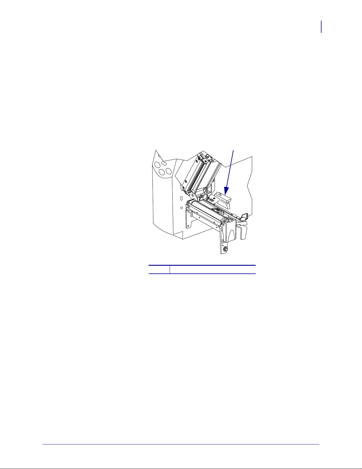
Position the Media Sensors
1
This printer uses two types of media sensors: transmissive and reflective.
Select the Transmissive Sensor
The standard transmissive sensor (Figure 21) is in a fixed position and enabled from the
control panel. For more information about the operation of this sensor, see Select the Media
Sensor on page 62.
Figure 21 • Transmissive Sensor
Operations
Position the Media Sensors
47
1
Adjust the Reflective Sensor
The reflective sensor is compatible with most types of media. With non-continuous media, the
reflective sensor detects the start-of-label indicator (the notch, hole, black mark, or gap
between die-cut labels). With both continuous media and non-continuous media, the sensor
detects an out-of-paper condition. If you have difficulties with calibration while using this
sensor, use the transmissive sensor (see Select the Transmissive Sensor on page 47).
Position the reflective sensor in the following way:
• directly under the notch, hole, or black mark with these types of labels
• anywhere along the width of the media if there is a gap between labels
• anywhere under the media for continuous media
The glow of the red light through the media may help you accurately position the sensor.
Standard transmissive sensor
10/21/05 S4M User Guide 13290L-001 Rev. A
Page 54
Operations
48
Position the Media Sensors
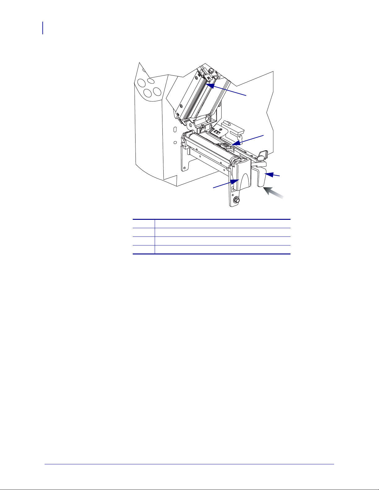
Figure 22 • Adjusting the Reflective Sensor
1
2
3
4
Printhead assembly
1
Reflective sensor
2
Adjustment lever
3
Printhead release latch
4
To adjust the reflective sensor, complete these steps:
1. See Figure 22. Press the printhead release latch.
2. Lift the printhead until it latches open.
3. Locate the reflective sensor positioning lever.
4. Move the reflective sensor positioning lever across the width of the media until the
reflective sensor aligns with the gap or notch.
5. Close the printhead assembly.
13290L-001 Rev. A S4M User Guide 10/21/05
Page 55

Adjust Printhead Pressure
See Figure 23. You may need to adjust printhead pressure if printing is too light on one side or
if you use thick media.
Figure 23 • Printhead Pressure Adjustment Dials
Operations
Adjust Printhead Pressure
49
1
1
2
2
Right dial
Left dial
The smallest block (fully counterclockwise) is considered position 1 and the largest block
(fully clockwise) is considered position 4.
To set printhead pressure, complete these steps:
1. Use Tabl e 6 to select the initial dial settings for your media.
Table 6 • Printhead Pressure
Media Width Left Dial Right Dial
1 in. (25.4 mm)
2 in. (51 mm)
3 in. (76 mm)
3.5 in. and up (89 mm and up)
10/21/05 S4M User Guide 13290L-001 Rev. A
31
41
32
33
Page 56

Operations
50
Adjust Printhead Pressure
2. If necessary, adjust the pressure adjustment dials as follows:
If the media... Then...
Requires higher pressure to
Increase both dials one position.
print well
Shifts left while printing Increase the right dial setting one position, or
decrease the left dial setting one position.
Shifts right while printing Increase the left dial setting one position, or decrease
the right dial setting one position.
13290L-001 Rev. A S4M User Guide 10/21/05
Page 57

4
Configuration
This section discusses printer configuration settings and instructs you how to view or change
printer parameters through the control panel.
Contents
Setup Mode . . . . . . . . . . . . . . . . . . . . . . . . . . . . . . . . . . . . . . . . . . . . . . . . . . . . . . . . . . . 52
Enter Setup Mode . . . . . . . . . . . . . . . . . . . . . . . . . . . . . . . . . . . . . . . . . . . . . . . . . . . . 52
Leave Setup Mode. . . . . . . . . . . . . . . . . . . . . . . . . . . . . . . . . . . . . . . . . . . . . . . . . . . . 52
Password Protection of Parameters. . . . . . . . . . . . . . . . . . . . . . . . . . . . . . . . . . . . . . . . . 54
Printing Configuration Labels. . . . . . . . . . . . . . . . . . . . . . . . . . . . . . . . . . . . . . . . . . . . . . 56
Control Panel LCD Display . . . . . . . . . . . . . . . . . . . . . . . . . . . . . . . . . . . . . . . . . . . . . . . 60
Password Level 1 and 2 Parameters . . . . . . . . . . . . . . . . . . . . . . . . . . . . . . . . . . . . . . 60
Password Level 3 Parameters . . . . . . . . . . . . . . . . . . . . . . . . . . . . . . . . . . . . . . . . . . . 65
10/21/05 S4M User Guide 13290L-001 Rev. A
Page 58

Configuration
52
Setup Mode
Setup Mode
Enter Setup Mode
After you have installed the media and ribbon and the Power-On Self Test (POST) is complete,
the control panel displays
application using the control panel LCD and the buttons directly below it. If it becomes
necessary to restore the initial printer defaults, see FEED and PAUSE Self Test on page 103.
Important • Certain printing conditions may require that you adjust some printing
parameters, such as print speed or darkness. These conditions include (but are not limited to):
• printing at high speeds
• peeling the media
• the use of extremely thin, small, synthetic, or coated labels
Because these and other factors affect print quality, run tests to determine the best
combination of printer settings and media for your application. A poor match may limit print
quality or print rate, or the printer may not function properly in the desired print mode.
PRINTER READY. You may now set printer parameters for your
To enter Setup mode, complete these steps:
1. Press MENU.
2. Use the left or right arrow to scroll through the parameters.
Leave Setup Mode
You can leave Setup mode at any time. As you leave Setup mode, you may choose to save or
discard changes that you made, or you may return to where you were in Setup mode.
To exit Setup mode, complete these steps:
1. Press MENU.
The printer displays
2. Do you wish to save changes that were made since you entered Setup mode?
If you wish to... Then...
Save changes a. Press ENTER.
SAVE CHANGES and activates the ENTER button.
The printer saves changes and exits Setup mode.
13290L-001 Rev. A S4M User Guide 10/21/05
Page 59

If you wish to... Then...
Discard changes a. Press the up or down arrow to select NO.
b. Press ENTER.
The printer discards changes and exits Setup mode.
Configuration
Setup Mode
53
Return to Setup mode
a. Press MENU or any arrow button.
• MENU returns you to the same parameter.
• The left arrow takes you to the previous parameter.
• The right arrow takes you to the next parameter.
• The up or down arrow scroll to other options in the
same parameter.
10/21/05 S4M User Guide 13290L-001 Rev. A
Page 60

Configuration
54
Password Protection of Parameters
Password Protection of Parameters
The printer has four levels of passwords. When you enter Setup mode on the control panel,
only those parameters that are not password-protected are displayed. To see more parameters,
you must enter an appropriate password at the
password correctly, you do not have to enter it again until you leave and reenter Setup mode.
When you are prompted for a password, enter the password for the level displayed or for a
higher level. Entering a higher level password will unprotect the parameters for that level and
for all levels below it (for example, unprotecting level 4 parameters also unprotects levels 1, 2,
and 3).
The password levels and default passwords are shown in Table 7. To change the password for
any level, use the
on page 112.
^KP ZPL II command. For more information, see ^KP, Define Password
Table 7 • Password Levels and Defaults
ADVANCED SETUP prompt. After you enter a
Password
Level
4 All features, including sensor adjustments
3 Installation and reconfiguration. The printer
2 Label configuration operations (media type,
1 Darkness, Tear-Off position, label top
Features Controlled Default Password
and other sensitive parameters
web-page interface also uses this password.
label removal method, label length)
To enter a password when prompted, complete these steps:
1. When the printer displays ADVANCED SETUP X, press ENTER.
The printer displays
2. Enter the four-digit password for the password level displayed or for a higher level.
• The left and right arrows change the selected digit position.
• The up and down arrows change the value of the selected digit.
PASSWORD and the number 0000.
For advanced use only. See the
Maintenance Manual or contact
technical support.
1234
0000 (unprotected)
0000 (unprotected)
3. After entering the password, press ENTER.
If you entered a valid password, additional parameters are displayed.
13290L-001 Rev. A S4M User Guide 10/21/05
Page 61

Configuration
Password Protection of Parameters
Note • When you enter a password at an ADVANCED SETUP prompt, the first parameter
that you see is determined in part by whether you pressed the right arrow or the left arrow to
get to the
ADVANCED SETUP prompt:
• If you used the right arrow, the first parameter that you see is based on the password level
that the printer prompted for (see Tabl e 8).
• If you used the left arrow, the first parameter that you see is based on which password you
enter at the prompt, regardless of which password level the printer prompted for
(see Table 9).
55
Table 8 • Right Arrow Used to Reach
Advanced
Setup Level
Prompted
Password
Level
Entered
First Parameter Seen
ADVANCED SETUP Prompt
1 1, 2, 3, or 4 DARKNESS (top of level 1)
2 2, 3, or 4
33 or 4
44
Table 9 • Left Arrow Used to Reach
Advanced
Setup Level
Prompted
Password
Level
Entered
MEDIA TYPE (top of level 2)
PRINT OUT (top of level 3)
LABEL LEVEL (top of level 4)
ADVANCED SETUP Prompt
First Parameter Seen
11 LABEL TOP (ZPL, EPL, APL-D)
(bottom of level 1)
Y FORMS ADJUST (APL-I)
(bottom of level 1)
1, 2 2
LENGTH
(bottom of level 2)
1, 2, 3 3
LANGUAGE
(bottom of level 3)
1, 2, 3, or 4 4
LANGUAGE
(bottom of level 4;
LANGUAGE parameter appears in
both level 3 and 4)
10/21/05 S4M User Guide 13290L-001 Rev. A
Page 62

Configuration
56
Printing Configuration Labels
Printing Configuration Labels
After you load the media and ribbon (if necessary), print a printer configuration label and a
network configuration label as records of your printer’s current settings. Keep the labels to use
when troubleshooting printing problems. The options to print these labels are located in
password level 3.
A configuration label lists the printer settings that are stored in configuration memory. A
network configuration label lists the print server settings. For the correct settings, print a
network configuration label after the printer connects to the network.
Note • If the printer is paused when you enter Setup mode, these labels will print after you exit
Setup mode and resume printing.
To print a printer configuration label or a network configuration label, complete
these steps:
1. On the control panel, press MENU.
The printer enters Setup mode and displays
DARKNESS.
2. Press the left arrow.
If a password is set for any levels, the printer displays
number, and the
ENTER button is enabled. If no passwords are set, the printer displays
LANGUAGE.
3. What does the printer display?
If the printer displays... Then...
ADVANCED SETUP 1
ADVANCED SETUP 2
ADVANCED SETUP 3
ADVANCED SETUP 4
LANGUAGE
a. Press ENTER.
The printer displays
b. Use the left and right arrows to enter the password for
level 3 or 4.
c. Press ENTER.
The printer displays
d. Use the left or right arrow to scroll through the
parameters until you reach
a. You do not need to enter a password to access this
parameter. Use the left or right arrow to scroll through
the parameters until you reach
a. Use the left or right arrow to scroll through the
parameters until you reach
ADVANCED SETUP with the level
PASSWORD 0000.
LANGUAGE.
PRINT OUT.
PRINT OUT.
PRINT OUT.
13290L-001 Rev. A S4M User Guide 10/21/05
Page 63

4. Select the type of label to print.
To print a... Then...
Printer configuration label a. Scroll to SETTINGS.
b. Press ENTER.
A printer configuration label prints (Figure 24).
Figure 24 • Printer Configuration Label
Configuration
Printing Configuration Labels
57
10/21/05 S4M User Guide 13290L-001 Rev. A
Page 64
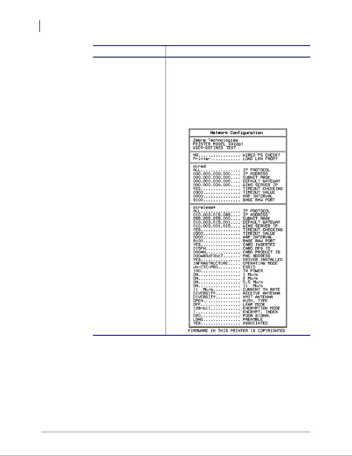
Configuration
58
Printing Configuration Labels
To print a... Then...
Network configuration label a. Scroll to LIST NETWORK.
b. Press ENTER.
A network configuration label prints (Figure 25). An
asterisk designates whether the wired or wireless print
server is active. If no wireless print server is installed,
the wireless portion of the label does not print.
Figure 25 • Network Configuration Label
13290L-001 Rev. A S4M User Guide 10/21/05
Page 65

Select a Display Language
The LANGUAGE parameter is included in password level 3 and level 4 so you can easily reach
the parameter to select a familiar language if you cannot read the one being displayed.
To change the language displayed, complete these steps:
1. On the control panel, press MENU.
The printer enters Setup mode.
2. Press the left arrow.
If a password is set for level 3 or 4, the printer displays
level number, and the
the printer displays
3. What does the printer display?
If the printer displays... Then...
ADVANCED SETUP 1
ADVANCED SETUP 2
ADVANCED SETUP 3
ADVANCED SETUP 4
LANGUAGE
* Displays in the last language selected.
*
ENTER button is enabled. If no passwords are set for level 3 or 4,
LANGUAGE.
Select a Display Language
ADVANCED SETUP with the
*
a. Press ENTER.
*
*
*
The printer displays
b. Use the left and right arrows to enter the password
for level 3 or 4.
c. Press ENTER.
The printer displays
Continue with the next step.
PASSWORD 0000
LANGUAGE
*
.
Configuration
*
.
59
4. Use the up and down arrows until you reach the language of your choice.
5. Press MENU.
The printer prompts you to accept changes.
6. Press ENTER to accept the language that you selected.
10/21/05 S4M User Guide 13290L-001 Rev. A
Page 66

Configuration
60
Control Panel LCD Display
Control Panel LCD Display
Use the LCD display on the control panel to adjust printer settings.
Password Level 1 and 2 Parameters
Table 10 shows parameters in the order in which they appear when you press the right arrow
after entering Setup mode. Throughout this process, press the right arrow to continue to the
next parameter or the left arrow to return to the previous parameter in the cycle.
Table 10 • Printer Parameters, Password Levels 1 and 2 (Page 1 of 5)
Parameter Explanation
DARKNESS
(ZPL, APL-D, and APL-I
modes)
DENSITY
(EPL mode only)
Adjust Print Darkness
The best darkness setting depends on a variety of factors, including ribbon
type, labels, and the condition of the printhead. You may adjust the
darkness for consistent high-quality printing.
Important • Set the darkness to the lowest setting that provides
good print quality. If the darkness is set too high, the ink may
smear, the ribbon may burn through, or the printhead may wear
prematurely.
Note • The printer applies and saves the darkness setting
immediately. Exiting Setup mode without saving changes does not
restore the previous value.
If printing is too light or if there are voids in the printed areas, increase the
darkness. If the printing is too dark or if there is spreading or bleeding of
printed areas, decrease the darkness. Darkness settings also may be
changed by the driver or software settings.
The FEED Self Test on page 100 can be used to determine the best
darkness setting. Because the darkness setting takes effect immediately,
you can see the results on labels that are currently printing.
Range (ZPL, APL-D, APL-I): 0.0 to +30.0
Default Value (ZPL, APL-D, APL-I): +10.0
Range (EPL): 7
Default Value (EPL): 0 to 15
To modify this parameter:
• Press the up arrow to increase value.
• Press the down arrow to decrease value.
13290L-001 Rev. A S4M User Guide 10/21/05
Page 67
Table 10 • Printer Parameters, Password Levels 1 and 2 (Page 2 of 5)
Parameter Explanation
Configuration
Control Panel LCD Display
61
TEAR OFF
LABEL TOP
(ZPL, EPL, and APL-D
modes)
X FORMS ADJUST
(APL-I mode only)
Adjust Tear-Off Position
This parameter establishes the position of the labels over the
tear-off/peel-off bar after printing. Each press of a button adjusts the tearoff position by one dot row.
Note • The printer applies and saves the tear-off setting
immediately. Exiting Setup mode without saving changes does not
restore the previous value.
Range (ZPL, EPL, APL-I): -120 to +120
Default Value (ZPL, EPL, APL-I): 0
Range (APL-D): +00i to +999i (inches), 0m to 2537m (metric)
Default Value (APL-D): +128i
Note • The APL-D default value does not position the label over
the tear-off/peel-off bar. This is done to work with existing DPL
label formats that account for this positioning.
To modify this parameter:
• Press the up arrow to increase value.
• Press the down arrow to decrease value.
Adjust Label Top Position
The label top position adjusts the print position vertically on the label.
Positive numbers adjust the label top position farther down the label (away
from the printhead), and negative numbers adjust the position up the label
(toward the printhead).
The displayed value represents dots.
Range (ZPL, EPL, and APL-I): -120 to +120
Default Value (ZPL, EPL, and APL-I): 0
Range (APL-D): -0.64i to 0.64i (when printer is set to operate in inches)
Default Value (APL-D): 0
To modify this parameter:
• To increase the value, press the up arrow.
• To decrease the value, press the down arrow.
Y FORMS ADJUST
(APL-I mode only)
Adjust Label Left Position
The label left position adjusts the print position horizontally on the label.
Positive numbers move the left edge of the image toward the center of the
label by the number of dots selected while negative numbers shift the left
edge of the image toward the left edge of the label.
Range: -120 to +120
Default Value: 0
To modify this parameter:
• To increase the value, press the up arrow.
• To decrease the value, press the down arrow.
10/21/05 S4M User Guide 13290L-001 Rev. A
Page 68

Configuration
62
Control Panel LCD Display
Table 10 • Printer Parameters, Password Levels 1 and 2 (Page 3 of 5)
Parameter Explanation
MEDIA TYPE
SENSOR SELECT
Set Media Type
This parameter tells the printer whether you are using continuous media,
non-continuous media or tag stock, or non-continuous black mark media
(see Types of Media on page 25).
Selections:
• GAP/NOTCH—Used for non-continuous web media,
non-continuous fanfold media, and tag stock. Use the SENSOR
SELECT
When using the transmissive sensor with media that has holes or
notches, position the media so that the transmissive media sensor
hole or notch. If the holes or notches cannot be positioned this way
for a particular type of media, use the reflective sensor.
• CONTINUOUS—Used for media that does not have divisions
between labels.
setting that gives the best results.
SENSOR SELECT should be set to DEFAULT or
TRANSMISSIVE.
• MARK—Used for non-continuous black mark media.
SELECT
Default Value: GAP/NOTCH
To modify this parameter:
• Press the up or down arrow to scroll through the selections.
Select the Media Sensor
You may allow the printer to select a media sensor based on the media
type, or you may select a specific media sensor to be used if the sensor that
was selected by the printer does not detect media correctly.
Selections:
• DEFAULT—The printer selects a sensor based on the setting
specified for
should be set to DEFAULT or REFLECTIVE.
MEDIA TYPE:
SENSOR
Media Type Sensor Used
GAP/NOTCH
CONTINUOUS
MARK
• TRANSMISSIVE—Use with all continuous media or with most
types of non-continuous media.
• REFLECTIVE—Use with black mark media or with non-continuous
media that does not work well with the transmissive sensor.
Default Value: DEFAULT
To modify this parameter:
• Press the up or down arrow to scroll through the selections.
13290L-001 Rev. A S4M User Guide 10/21/05
Transmissive
Transmissive
Reflective
Page 69
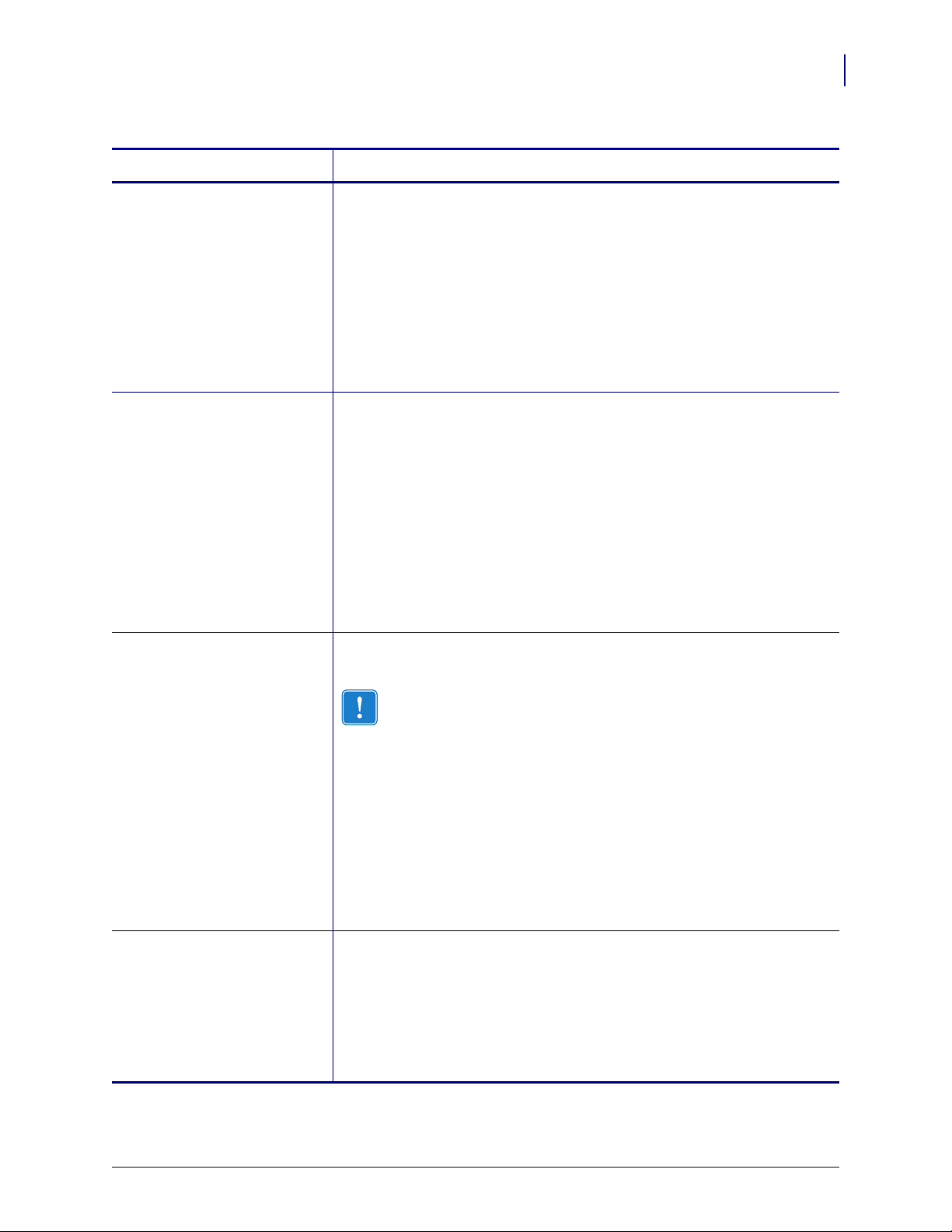
Table 10 • Printer Parameters, Password Levels 1 and 2 (Page 4 of 5)
Parameter Explanation
Configuration
Control Panel LCD Display
63
REMOVAL
PRINT SPEED
PRINT WIDTH
Select the Label Removal Method
The label removal must correspond to the print mode (see Print Modes
on page 30). Be sure to select a label removal mode that your hardware
configuration supports because some of the selections displayed are for
optional printer features.
Selections: TEAR, PEEL, CUTTER, REWIND, DELAYED CUT
Default Value: TEAR
To modify this parameter:
• Press the up or down arrow to scroll through the selections.
Adjust Print Speed
Adjusts the speed for printing a label (given in whole numbers of inches
per second). Slower print speeds typically yield better print quality. Print
speed changes take effect upon exiting Setup mode.
Range: 2 to 6 IPS
Default Value (ZPL, APL-I): 2 IPS
Default Value (EPL, APL-D): 6 IPS
To modify this parameter:
• To increase the value, press the up arrow.
• To decrease the value, press the down arrow.
Set Print Width
Print width determines the printable area across the width of the label.
Important • Setting the width too narrow can result in portions of
the label not being printed on the media. Setting the width too
wide wastes formatting memory and can cause printing off the
label and on the platen roller. This setting can affect the horizontal
position of the label format if the image was inverted using the
^POI ZPL II command.
Range: 2 to 832 for 8 dots/mm, 2 to 1248 for 12 dots/mm
Default Value: 832 for 8 dots/mm, 1248 for 12 dots/mm
To modify this parameter:
• To increase the value, press the up arrow.
• To decrease the value, press the down arrow.
COMPAT. MODE
(APL-D mode only)
Set APL-D Compatibility Mode
Sets compatibility with DPL printers.
Selections: ON, OFF
Default Value: OFF
To modify this parameter:
• Press the up or down arrow to scroll through the selections.
10/21/05 S4M User Guide 13290L-001 Rev. A
Page 70

Configuration
64
Control Panel LCD Display
Table 10 • Printer Parameters, Password Levels 1 and 2 (Page 5 of 5)
Parameter Explanation
CONTROL CODES
(APL-D mode only)
MODULE A
(APL-D mode only)
MODULE B
(APL-D mode only)
RESOLUTION
(APL-I mode only)
Set APL-D Control Codes
Selections: STANDARD, MAINFRAME
Default Value: STANDARD
To modify this parameter:
• Press the up or down arrow to scroll through the selections.
Set Module A Storage Device for APL-D
Selections: NONE, RAM 1, RAM 2, FLASH 1, FLASH 2
Default Value: NONE
To modify this parameter:
• Press the up or down arrow to scroll through the selections.
Set Module B Storage Device for APL-D
Selections: NONE, RAM 1, RAM 2, FLASH 1, FLASH 2
Default Value: NONE
To modify this parameter:
• Press the up or down arrow to scroll through the selections.
Set Printer Resolution for APL-I
Sets the dot size for backward compatibility with some older APL-I
printers.
Selections: 5 MIL, 10 MIL, 15 MIL
Default Value: 5 MIL
LENGTH
To modify this parameter:
• Press the up or down arrow to scroll through the selections.
Set Maximum Label Length
Maximum label length is used in conjunction with the calibration
procedure. The value of this setting is the maximum label length that is
used during the media portion of the calibration process. Only a few labels
are required to set media sensors. Always set the value that is at least 1 in.
(25.4 mm) longer than the longest label to be used on the printer.
Selections:
Default Value:
To modify this parameter:
AUTO, < 1 INCH (25.4 mm) to < 39 INCH (991 mm)
AUTO
• To increase the value, press the up arrow.
• To decrease the value, press the down arrow.
13290L-001 Rev. A S4M User Guide 10/21/05
Page 71

Password Level 3 Parameters
Table 11 shows parameters in the order in which they appear when you press the right arrow
after entering the Level 3 password. Throughout this process, press the right arrow to continue
to the next parameter or the left arrow to return to the previous parameter in the cycle.
Table 11 • Printer Parameters, Level 3 (Page 1 of 9)
Parameter Explanation
Configuration
Control Panel LCD Display
65
PRINT OUT
Print Selected Labels
This parameter allows you to print certain types of labels with information
about the printer.
Selections:
SETTINGS—Prints a printer configuration label. See Printing
•
Configuration Labels on page 56.
FONTS (ZPL, EPL, APL-D)—Prints a label that lists the available
•
fonts in the printer, including standard printer fonts plus any optional
fonts. Fonts may be stored in RAM, Flash memory, optional memory
cards, or font cards.
FORMATS (ZPL, EPL, APL-D)—Prints a label that lists the
•
available formats stored in the printer’s RAM, Flash memory, or
optional memory card.
BARCODES (ZPL only)—Prints a label that lists the available bar
•
codes in the printer.
ALL (ZPL, EPL)—Prints labels that list the available fonts, bar
•
codes, images, formats, and the current printer and network
configurations.
•
IMAGES (ZPL, EPL, APL-D)—Prints a label that lists the images
currently stored in the printer’s RAM, Flash memory, or optional
memory cards.
•
NETWORK (ZPL only)—Prints a network configuration label. See
Printing Configuration Labels on page 56.
•
APLI SW SETUP (APL-I only)
•
APLI HW SETUP (APL-I only)
• APLI PRT QUAL (APL-I only)
•
APLI PITCH (APL-I only)
To print labels:
1. Press the up or down arrow to display label choices.
2. Press ENTER to print the desired label.
PARALLEL COMM.
10/21/05 S4M User Guide 13290L-001 Rev. A
Set Parallel Communications
Select the communications port that matches the one being used by the host
computer.
Selections: UNIDIRECTIONAL, BIDIRECTIONAL
Default Value: UNIDIRECTIONAL
To modify this parameter:
• Press the up or down arrow to scroll through the selections.
Page 72

Configuration
66
Control Panel LCD Display
Table 11 • Printer Parameters, Level 3 (Page 2 of 9)
Parameter Explanation
PRINT PAGE
(APL-I mode only)
PRINT FORMAT
(APL-I mode only)
BAUD
Print Stored APL-I Page
Up to 20 pages can be stored and printed.
Selections: 0 through 19
Default Value: 0
To modify this parameter:
• To increase the value, press the up arrow.
• To decrease the value, press the down arrow.
Print Stored APL-I Format
Up to 100 formats can be stored and printed.
Selections: 0 through 99
Default Value: 0
To modify this parameter:
• To increase the value, press the up arrow.
• To decrease the value, press the down arrow.
Set Baud
The baud setting of the printer must match the baud setting of the host
computer for accurate communications to take place. Select the value that
matches the one being used by the host computer.
Selections: 300, 600, 1200, 2400, 4800, 9600, 14400, 19200, 28800,
38400, 57600, 115200
Default Value: 9600
DATA BITS
To modify this parameter:
• Press the up or down arrow to scroll through the selections.
Set Data Bits
The data bits of the printer must match the data bits of the host computer
for accurate communications to take place. Set the data bits to match the
setting being used by the host computer.
Note • Code Page 850 requires the data bits to be set to 8 bits.
Selections: 7BITS, 8BITS
Default Value: 8BITS
To modify this parameter:
• Press the up or down arrow to scroll through the selections.
13290L-001 Rev. A S4M User Guide 10/21/05
Page 73

Table 11 • Printer Parameters, Level 3 (Page 3 of 9)
Parameter Explanation
Configuration
Control Panel LCD Display
67
STATUS RESPONSE
(APL-I mode only)
RESPONSE FORMAT
(APL-I mode only)
PARITY
Send APL-I Status Response
Determines if a response is sent after inquiry commands. The format is set
with the
RESPONSE FORMAT parameter.
Selections: ON, OFF
Default Value: ON
To modify this parameter:
• Press the up or down arrow to scroll through the selections.
Select APL-I Response Format
STATUS RESPONSE is set to ON, this parameter determines the
If
format of the response.
Selections: ASCII, BINARY
Default Value: ASCII
To modify this parameter:
• Press the up or down arrow to scroll through the selections.
Set Parity
The parity of the printer must match the parity of the host computer for
accurate communications to take place. Select the parity that matches the
one being used by the host computer.
Selections: NONE, ODD, EVEN
Default Value: NONE
HOST HANDSHAKE
To modify this parameter:
• Press the up or down arrow to scroll through the selections.
Set Host Handshake
The handshake protocol of the printer must match the handshake protocol
of the host computer for proper communications to take place. Select the
handshake protocol that matches the one being used by the host computer.
Selections (ZPL, APL-D): XON/XOFF, DSR/DTR, RTS/CTS
Selections (EPL): DTR & XON/XOF, DTR, XON/XOFF
Selections (APL-I): XON/XOFF, DSR/DTR, RTS/CTS, APL-I
Default Value: XON/XOFF
To modify this parameter:
• Press the up or down arrow to scroll through the selections.
10/21/05 S4M User Guide 13290L-001 Rev. A
Page 74

Configuration
68
Control Panel LCD Display
Table 11 • Printer Parameters, Level 3 (Page 4 of 9)
Parameter Explanation
CONTROL CHAR
(ZPL mode only)
COMMAND CHAR
(ZPL mode only)
Set Control Character
The printer looks for this two-digit hexadecimal character to indicate the
start of a ZPL/ZPL II control instruction.
Note • Do not use the same hexadecimal value for the control,
command, and delimiter character. The printer must see different
characters to work properly.
Range: 00 to FF
Default Value: 7E (tilde—displayed as an arrow)
To modify this parameter:
• To increase the value, press the up arrow.
• To decrease the value, press the down arrow.
Set Command Character
The command prefix is a two-digit hexadecimal value used as a parameter
place marker in ZPL/ZPL II format instructions. The printer looks for this
two-digit hexadecimal character to indicate the start of a ZPL/ZPL II
format instruction. See the ZPL II Programming Guide Volume I for more
information.
Note • Do not use the same hexadecimal value for the control,
command, and delimiter character. The printer must see different
characters to work properly.
Range: 00 to FF
Default Value: 5E (caret)
DELIM. CHAR
(ZPL mode only)
To modify this parameter:
• To increase the value, press the up arrow.
• To decrease the value, press the down arrow.
Set Delimiter Character
The delimiter character is a two-digit hexadecimal value used as a
parameter place marker in ZPL/ZPL II format instructions. See the ZPL II
Programming Guide Volume I for more information.
Note • Do not use the same hexadecimal value for the control,
command, and delimiter character. The printer must see different
characters to work properly.
Range: 00 to FF
Default Value: 2C (comma)
To modify this parameter:
• To increase the value, press the up arrow.
• To decrease the value, press the down arrow.
13290L-001 Rev. A S4M User Guide 10/21/05
Page 75

Table 11 • Printer Parameters, Level 3 (Page 5 of 9)
Parameter Explanation
Configuration
Control Panel LCD Display
69
HEXDUMP
(ZPL, EPL, APL-D modes)
CHANGE RTC DATE
Hex Dump
The hexadecimal dump mode is a troubleshooting tool for checking the
interconnection between the printer and the host computer. When
YES is
selected, all data sent from the host computer to the printer prints as
straight ASCII characters, with the hexadecimal value below the ASCII
text. The printer prints all characters received, including control codes,
such as
CR (carriage return). A sample printout is shown in
Communications Diagnostics Test on page 103.
Selections: NO, YES
Default Value: NO
To modify this parameter:
• Press the up or down arrow to scroll through the selections.
Set RTC (Real-time clock) Date
If RTC is installed, this parameter allows you to set the RTC date.
Note • The printer saves the RTC date immediately.
To modify this parameter:
1. Press ENTER.
The printer displays the current RTC date.
2. Modify the values as follows:
• Press the right arrow to move to the next digit position.
• To increase the value, press the up arrow.
• To decrease the value, press the down arrow.
3. Press ENTER to accept the value shown.
CHANGE RTC TIME
Set RTC (Real-time clock) Time
If RTC is installed, this parameter allows you to set the RTC time.
Note • The printer saves the RTC time immediately.
To modify this parameter:
1. Press ENTER.
The printer displays the current RTC time.
2. Modify the values as follows:
• Press the right arrow to move to the next digit position.
• To increase the value, press the up arrow.
• To decrease the value, press the down arrow.
3. Press ENTER to accept the value shown.
10/21/05 S4M User Guide 13290L-001 Rev. A
Page 76

Configuration
70
Control Panel LCD Display
Table 11 • Printer Parameters, Level 3 (Page 6 of 9)
Parameter Explanation
LOAD DEFAULTS
INIT FLASH MEM
Load Factory Defaults
Sets all parameters back to factory defaults.
Important • Use care when using this command. All printer
parameters are reset to factory values with this command. If
possible, print a configuration label to have as a record of the
printer’s settings before loading defaults.
How to select this parameter:
1. Press ENTER.
The printer asks
2. To load factory defaults, press ENTER to select YES. To cancel, press
ARE YOU SURE?
any other key.
Initialize Flash Memory
This parameter allows you to erase the printer’s Flash memory.
Important • The internal Flash memory is entirely erased with this
command.
To select this parameter:
1. Press ENTER to select YES.
The printer asks
2. To initialize Flash memory, press ENTER. To cancel, press any other
ARE YOU SURE?
key.
RIBBON
Set Ribbon Use
Note • This parameter appears only for printers that have the
Thermal Transfer option installed.
The printer can automatically detect if you are using ribbon. However, you
may use this parameter to tell the printer the method of printing that you
wish to use each time: direct thermal (no ribbon) or thermal transfer (using
ribbon).
Selections:
• AUTO (the printer detects if ribbon is present)
• NO (direct thermal mode, no ribbon)
• YES (thermal transfer mode, with ribbon)
Default Value: AUTO
To modify this parameter:
• Press the up or down arrow to scroll through the selections.
13290L-001 Rev. A S4M User Guide 10/21/05
Page 77

Table 11 • Printer Parameters, Level 3 (Page 7 of 9)
Parameter Explanation
Configuration
Control Panel LCD Display
71
ZPL OVERRIDE
(ZPL mode only)
EPL OVERRIDE
(EPL mode only)
Override Certain ZPL Commands
Prevents the printer from accepting the following ZPL commands:
^MM (media mode)
•
•
^MT (media type direct thermal or thermal transfer)
•
^MN (media non-continuous or continuous)
Selections:
• NO—allows the printer to accept the listed ZPL commands.
• YES—tells the printer to ignore the listed ZPL commands.
Default Value: NO
To modify this parameter:
• Press the up or down arrow to scroll through the selections.
Override Certain EPL Commands
Prevents the printer from accepting certain EPL commands.
Selections:
• DISABLED—allows the printer to accept the listed EPL commands.
• ENABLED—tells the printer to ignore the listed EPL commands.
Default Value: DISABLED
To modify this parameter:
• Press the up or down arrow to scroll through the selections.
SENSOR PROFILE
Print Sensor Profile
Use the sensor profile (Figure 26) to troubleshoot registration problems
that may occur if the media sensor detects preprinted areas on the media or
if it experiences difficulty in determining web location. To adjust the
sensitivity of the media and/or ribbon sensors, use Calibrate Media and
Ribbon Sensors on page 72.
Note • The ribbon portion of the label appears only for printers
that have the Thermal Transfer option installed.
Figure 26 • Sensor Profile
To select this parameter:
1. Press ENTER to start this standard calibration procedure and print a
media sensor profile.
10/21/05 S4M User Guide 13290L-001 Rev. A
Page 78

Configuration
72
Control Panel LCD Display
Table 11 • Printer Parameters, Level 3 (Page 8 of 9)
Parameter Explanation
MEDIA/RIBBON
CALIBRATE
(Thermal Transfer only)
MEDIA CALIBRATE
(Direct Thermal only)
Calibrate Media and Ribbon Sensors
Use this procedure to adjust the sensitivity of the printer’s sensors. In a
printer that has the Thermal Transfer option installed, both media and
ribbon sensors are adjusted. In a Direct Thermal printer (no Thermal
Transfer option installed), only media sensors are adjusted, and the LCD
displays for ribbon do not appear in this procedure.
Important • This procedure must be followed exactly as presented.
All of the steps must be performed even if only one of the sensors
requires adjustment. You may press the left arrow at any step in this
procedure to cancel the procedure.
How to select this parameter:
1. Press ENTER to start the calibration procedure.
The
LOAD BACKING/REMOVE RIBBON prompt displays.
2. Open the printhead.
3. Remove approximately 8 in. (203 mm) of labels from the backing,
and pull the media into the printer so that only the backing is between
the media sensors.
4. Remove the ribbon (if used).
5. Press the right arrow to continue.
The message
CALIBRATING PLEASE WAIT displays.
The printer adjusts the scale (gain) of the signals that it receives from
the media and ribbon sensors. On the sensor profile, this essentially
corresponds to moving the peak of the graph up or down to optimize
the readings for your application.
RELOAD ALL displays.
6. Reload the media and ribbon (if used).
7. Close the printhead.
8. Press the right arrow to continue.
The message
The printer does a calibration; during this process, the printer
determines the label length. To see the new readings on the new scale,
print a sensor profile.
CALIBRATING PLEASE WAIT displays.
13290L-001 Rev. A S4M User Guide 10/21/05
Page 79

Table 11 • Printer Parameters, Level 3 (Page 9 of 9)
Parameter Explanation
Configuration
Control Panel LCD Display
73
LANGUAGE
Select the Display Language
This parameter allows you to display the control panel in the language of
your choice. As soon as you select a language, all parameters are
displayed in that language. Save changes as you exit Setup mode to save
the language setting.
Selections: English (
FRANCAIS), German (Deutsch), Italian (ITALIANO), Norwegian
(
NORSK), Portuguese (PORTUGUES), Swedish (SVENSKA), Danish
(
(
DANSK), Spanish2 (ESPANOL2), Dutch (NEDERLANDS), Finnish
SUOMI), and Japanese.
(
Default Value: ENGLISH
To modify this parameter:
• Press the up or down arrow to scroll through the selections.
ENGLISH), Spanish (ESPANOL), French
10/21/05 S4M User Guide 13290L-001 Rev. A
Page 80
Configuration
74
Control Panel LCD Display
ZebraNet®Wired and Wireless Print Server LCD Displays
The menu options shown in Table 1 2 display only if you have the ZebraNet PrintServer II, or
10/100 PrintServer, or Wireless Print Server installed and are operating in ZPL or EPL mode.
These parameters are considered part of Level 3.
Table 12 • Print Server LCD Displays (Page 1 of 2)
Parameter Explanation
OBTAIN IP ADDRESS
CHANGE IP ADDRESS
CHANGE SUBNET
Obtain an IP Address
Selects the method by which an IP address will be assigned to the printer.
Selections: AUTO SELECT (dynamic), PERMANENT (user-specified)
Default Value: AUTO SELECT
To modify this parameter:
• Press the up or down arrow to scroll through the selections.
Change the Printer’s IP Address
This parameter can be modified only when PERMANENT is selected for
OBTAIN IP ADDRESS.
Selections: 0 to 255 for each field
Default Value: 0.0.0.0
Note • Leading zeroes are not shown in the address. If an IP
address contains more digits than can be displayed at one time, use
the left or right arrows to scroll through the digits.
To modify this parameter:
• To increase the value, press the up arrow.
• To decrease the value, press the down arrow.
Change the Subnet
This parameter can be modified only when PERMANENT is selected for
OBTAIN IP ADDRESS.
Selections: 0 to 255 for each field
Default Value: 0.0.0.0
Note • Leading zeroes are not shown in the address. If an IP
address contains more digits than can be displayed at one time, use
the left or right arrows to scroll through the digits.
To modify this parameter:
• To increase the value, press the up arrow.
• To decrease the value, press the down arrow.
13290L-001 Rev. A S4M User Guide 10/21/05
Page 81
Table 12 • Print Server LCD Displays (Page 2 of 2)
Parameter Explanation
Configuration
Control Panel LCD Display
75
CHANGE GATEWAY
CHANGE IP PROTOCOL
Change the Gateway
This parameter can be modified only when PERMANENT is selected for
OBTAIN IP ADDRESS.
Selections: 0 to 255 for each field
Default Value: 0.0.0.0
Note • Leading zeroes are not shown in the address. If an IP
address contains more digits than can be displayed at one time, use
the left or right arrows to scroll through the digits.
To modify this parameter:
• To increase the value, press the up arrow.
• To decrease the value, press the down arrow.
Change the IP Protocol
Determines the method(s) by which the print server (wired or wireless)
receives the IP address from the server.
This parameter can be modified only when
OBTAIN IP ADDRESS.
for
Selections: ALL, GLEANING ONLY, RARP, BOOTP, DHCP,
DHCP AND BOOT
Default Value: ALL
To modify this parameter:
• Press the up or down arrow to scroll through the selections.
AUTO SELECT is selected
10/21/05 S4M User Guide 13290L-001 Rev. A
Page 82

Configuration
76
Control Panel LCD Display
Notes • ___________________________________________________________________
__________________________________________________________________________
__________________________________________________________________________
__________________________________________________________________________
__________________________________________________________________________
__________________________________________________________________________
__________________________________________________________________________
__________________________________________________________________________
__________________________________________________________________________
__________________________________________________________________________
13290L-001 Rev. A S4M User Guide 10/21/05
Page 83

Routine Maintenance
This section provides routine cleaning and maintenance procedures.
5
Contents
Lubrication . . . . . . . . . . . . . . . . . . . . . . . . . . . . . . . . . . . . . . . . . . . . . . . . . . . . . . . . . . . . 78
Cleaning Procedures . . . . . . . . . . . . . . . . . . . . . . . . . . . . . . . . . . . . . . . . . . . . . . . . . . . . 78
Clean the Exterior . . . . . . . . . . . . . . . . . . . . . . . . . . . . . . . . . . . . . . . . . . . . . . . . . . . . 78
Clean the Printhead and Platen Roller. . . . . . . . . . . . . . . . . . . . . . . . . . . . . . . . . . . . . 79
Clean the Media Compartment and Sensors. . . . . . . . . . . . . . . . . . . . . . . . . . . . . . . . 81
Clean the Peel-Off Assembly. . . . . . . . . . . . . . . . . . . . . . . . . . . . . . . . . . . . . . . . . . . . 82
10/21/05 S4M User Guide 13290L-001 Rev. A
Page 84
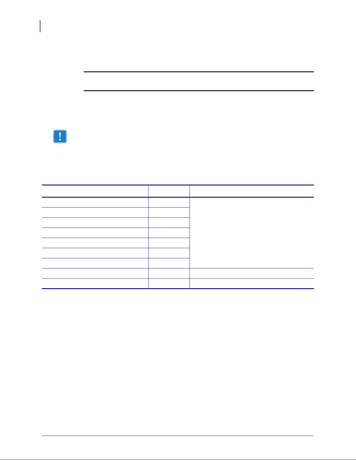
Routine Maintenance
78
Lubrication
Lubrication
No lubrication is needed for this printer.
Caution • Some commercially available lubricants will damage the finish and the
mechanical parts if used on this printer.
Cleaning Procedures
Important • Zebra is not responsible for damage caused by the use of cleaning fluids on this
printer.
Specific cleaning procedures are provided on the following pages. Table 13 shows the
recommended cleaning schedule.
.
Table 13 • Recommended Cleaning Schedule
Area Method Interval
Printhead Solvent* Direct Thermal Mode: After every roll of
Platen roller Solvent*
Media sensors Air blow
Ribbon sensor Air blow
Media path Solvent*
Ribbon path Solvent*
media (or 500 feet of fanfold media).
Thermal Transfer Mode: After every roll of
ribbon or three rolls of media.
These intervals are intended as guidelines only.
You may have to clean more often, depending
upon your application and media.
Pinch roller. (part of Peel-Off option) Solvent*
Tear-off/peel-off bar Solvent* Once a month.
Take label sensor Air blow Once every six months.
* Zebra recommends using Preventive Maintenance Kit (part number 47362) or a solution of 90% Isopropyl and
10% deionized water)
Clean the Exterior
You may clean the exterior surfaces of the printer with a lint-free cloth and a small amount of a
mild detergent, if necessary. Do not use harsh or abrasive cleaning agents or solvents.
13290L-001 Rev. A S4M User Guide 10/21/05
Page 85
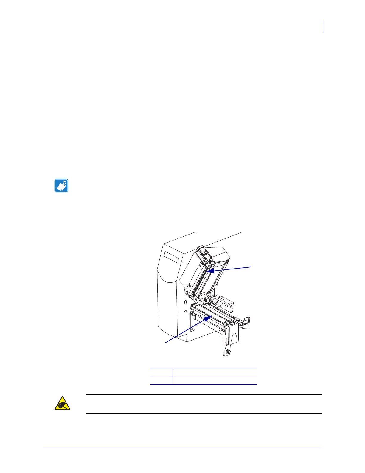
Clean the Printhead and Platen Roller
You can minimize printhead wear and maintain print quality with regular preventive measures.
Over time, the movement of media or ribbon across the printhead wears through the protective
ceramic coating, exposing and eventually damaging the print elements (dots). To avoid
abrasion:
• Clean the printhead frequently, and use well-lubricated thermal transfer ribbons with
backings optimized to reduce friction.
• Minimize printhead pressure and burn temperature settings by optimizing the balance
between the two.
• Ensure that the thermal transfer ribbon is as wide or wider than the label media to prevent
exposing the elements to the more abrasive label material.
For best results, clean the printhead after changing every roll of ribbon. Inconsistent print
quality, such as voids in the bar code or graphics, may indicate a dirty printhead.
Note • The printer can remain on while you are cleaning the printhead. In this way, all label
formats, images, and all temporary parameter settings stored in the printer’s internal memory
are saved. In addition, keep the peel engaged while cleaning the platen roller (media must be
unloaded to do this) to reduce the risk of bending the tear-off/peel-off bar.
Routine Maintenance
Cleaning Procedures
79
Figure 27 • Cleaning the Printhead and Platen Roller
1
2
Printhead assembly
1
Platen roller
2
Caution • Observe proper electrostatic safety precautions when handling any
static-sensitive components such as circuit boards and printheads.
10/21/05 S4M User Guide 13290L-001 Rev. A
Page 86
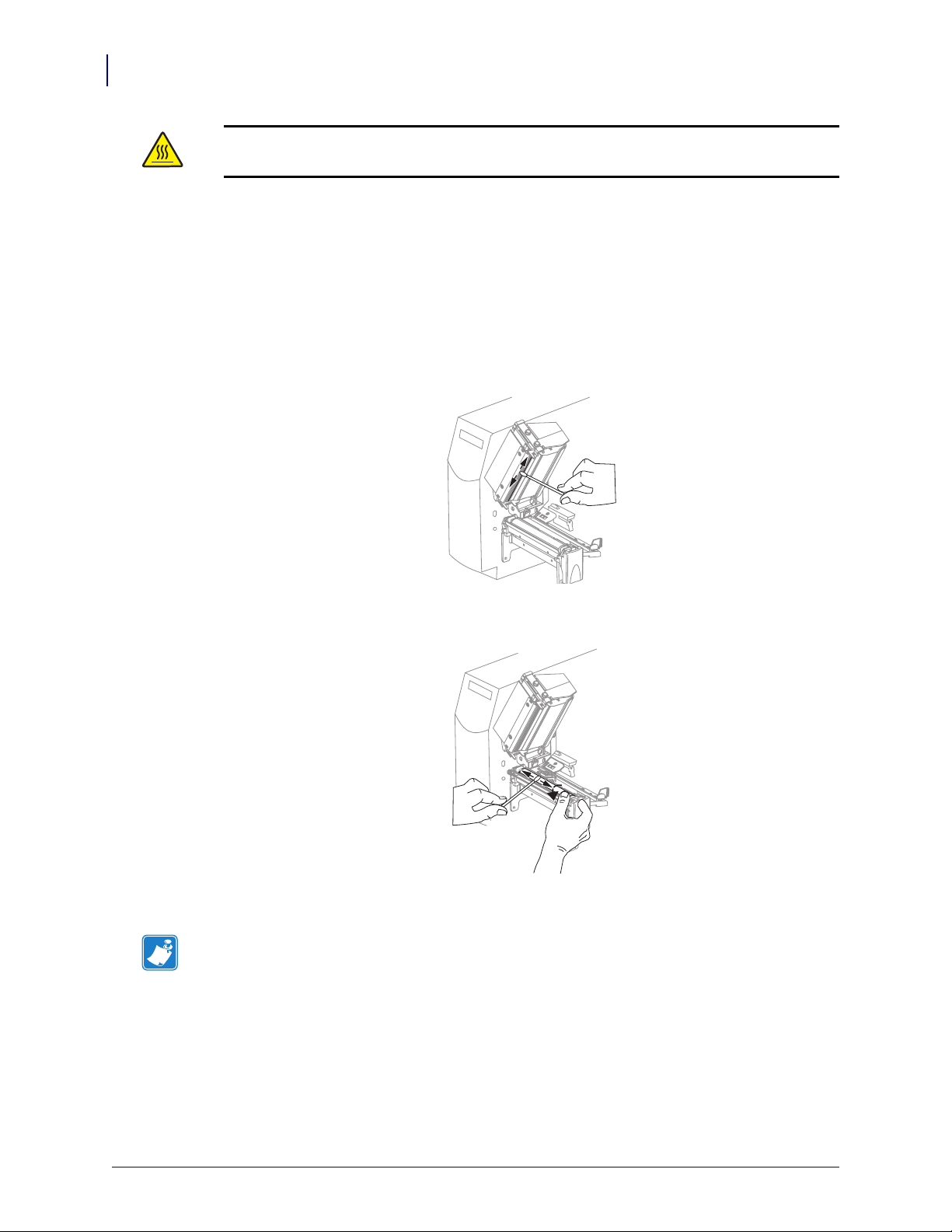
Routine Maintenance
80
Cleaning Procedures
Caution • The printhead may be hot and could cause severe burns. Allow the printhead to
cool.
To clean the printhead and platen roller, complete these steps:
1. Open the printhead assembly.
2. Remove the media and ribbon.
3. Using the swab from the Preventive Maintenance Kit (part number 47362) or a solution of
90% Isopropyl alcohol and 10% deionized water and a cotton swab, wipe along the brown
strip on the printhead assembly from end to end. Allow the solvent to evaporate.
4. While manually rotating the platen roller, clean it thoroughly with the swab. Allow the
solvent to evaporate.
5. Reload media and ribbon, and close the printhead assembly.
Note • If performing this procedure does not improve print quality, try cleaning the
printhead with Save-A-Printhead cleaning film. This specially coated material removes
contamination buildup without damaging the printhead. Call your authorized Zebra
reseller for more information.
13290L-001 Rev. A S4M User Guide 10/21/05
Page 87
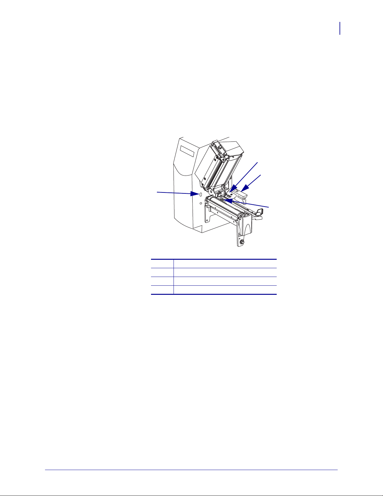
Clean the Media Compartment and Sensors
To clean the media compartment and sensors, complete these steps:
1. Brush or vacuum any accumulated paper lint and dust away from the media and ribbon
paths.
2. Brush or vacuum any paper lint and dust away from the sensors (see Figure 28).
Figure 28 • Cleaning the Sensors
1
Routine Maintenance
Cleaning Procedures
2
3
81
Take-label sensor
1
Ribbon sensor
2
Transmissive sensor
3
Reflective sensor
4
4
10/21/05 S4M User Guide 13290L-001 Rev. A
Page 88
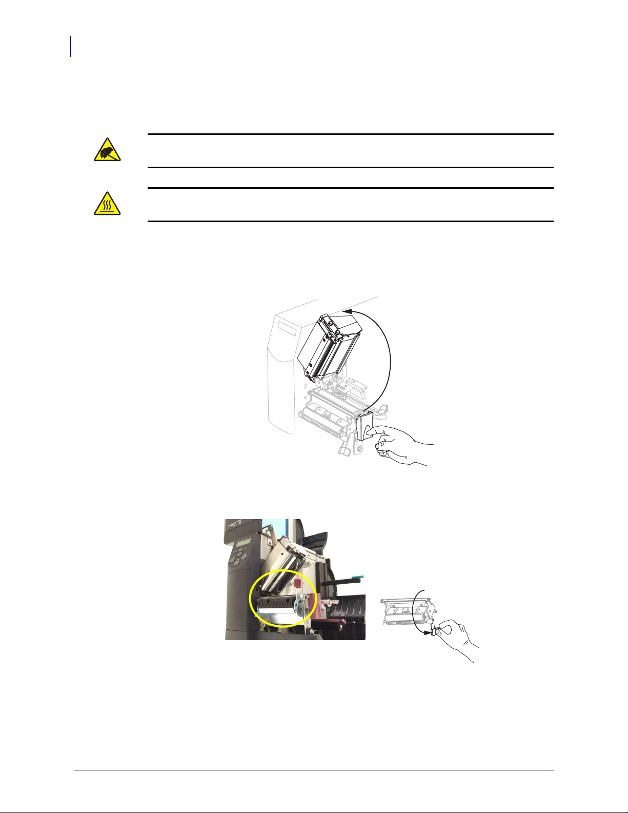
Routine Maintenance
82
Cleaning Procedures
Clean the Peel-Off Assembly
The Peel-Off option is required.
Caution • Observe proper electrostatic safety precautions when handling any
static-sensitive components such as circuit boards and printheads.
Caution • The printhead may be hot and could cause severe burns. Allow the printhead to
cool.
If adhesive buildup affects peel-off performance, complete these steps:
1. Press the printhead release latch to open the printhead assembly.
2. Lift the printhead until it latches open.
3. Open the peel assembly by pivoting the module toward you.
4. Remove any media backing to expose the pinch roller.
5. While manually rotating the pinch roller, clean it thoroughly with the swab from the
Preventive Maintenance Kit (part number 47362) or a solution of 90% Isopropyl alcohol
and 10% deionized water and a cotton swab. Allow the solvent to evaporate.
13290L-001 Rev. A S4M User Guide 10/21/05
Page 89
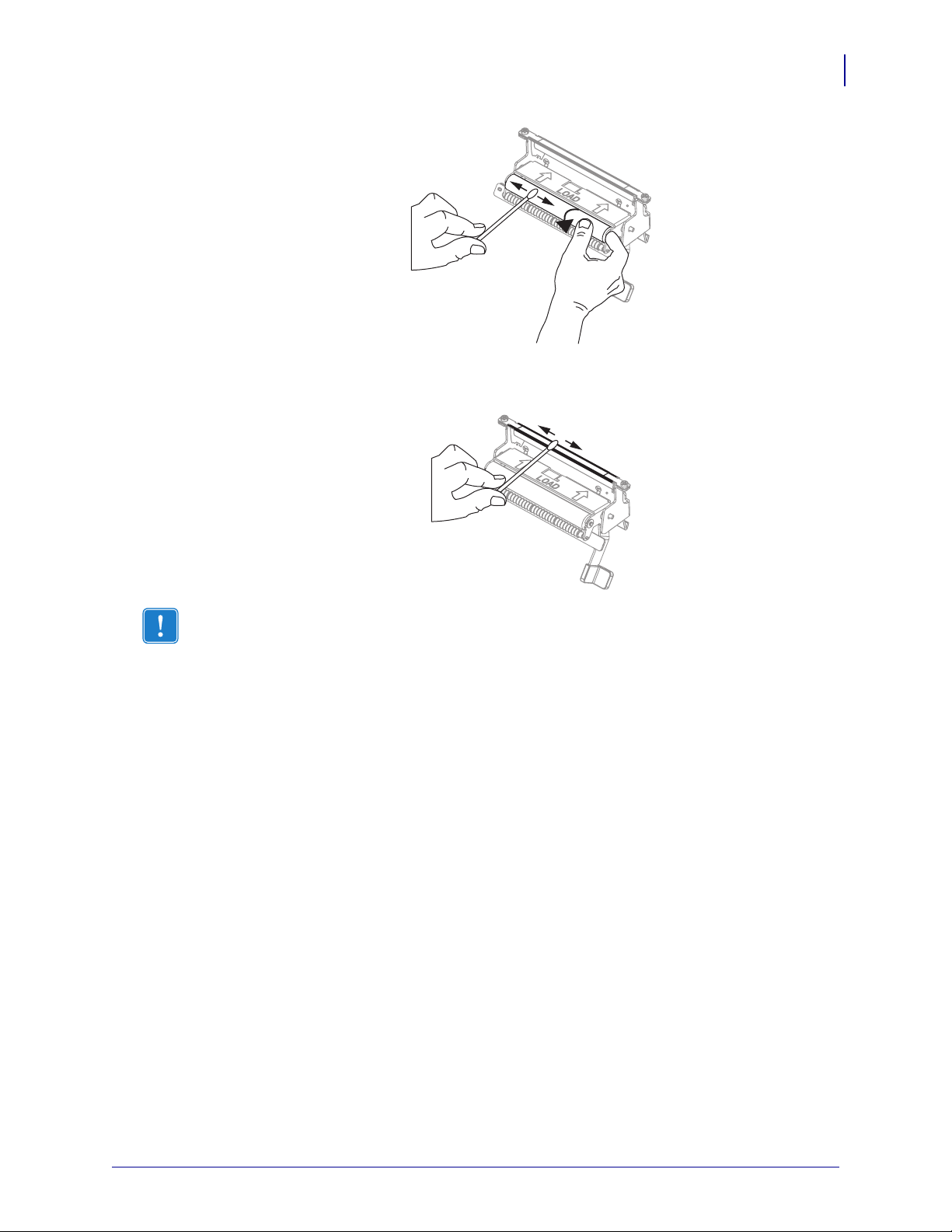
Routine Maintenance
Cleaning Procedures
6. Use the swab to remove excess adhesive from the tear-off/peel-off bar. Allow the solvent
to evaporate.
83
Important • Apply minimum force when cleaning the tear-off/peel-off bar. Excessive
force can cause the tear-off/peel-off bar to bend, which could have a negative effect on
peel performance.
7. Close the printhead assembly and the media door.
The printer is ready to operate.
10/21/05 S4M User Guide 13290L-001 Rev. A
Page 90

Routine Maintenance
84
Cleaning Procedures
Notes • ___________________________________________________________________
__________________________________________________________________________
__________________________________________________________________________
__________________________________________________________________________
__________________________________________________________________________
__________________________________________________________________________
__________________________________________________________________________
__________________________________________________________________________
__________________________________________________________________________
__________________________________________________________________________
13290L-001 Rev. A S4M User Guide 10/21/05
Page 91

6
Troubleshooting
This section provides information about errors that you might need to troubleshoot. Assorted
diagnostic tests are included.
Contents
Troubleshooting Checklists . . . . . . . . . . . . . . . . . . . . . . . . . . . . . . . . . . . . . . . . . . . . . . . 86
LCD Error Messages . . . . . . . . . . . . . . . . . . . . . . . . . . . . . . . . . . . . . . . . . . . . . . . . . . . . 87
Memory Errors . . . . . . . . . . . . . . . . . . . . . . . . . . . . . . . . . . . . . . . . . . . . . . . . . . . . . . . . . 89
Print Quality Problems . . . . . . . . . . . . . . . . . . . . . . . . . . . . . . . . . . . . . . . . . . . . . . . . . . . 90
Calibration Problems . . . . . . . . . . . . . . . . . . . . . . . . . . . . . . . . . . . . . . . . . . . . . . . . . . . . 93
Communications Problems . . . . . . . . . . . . . . . . . . . . . . . . . . . . . . . . . . . . . . . . . . . . . . . 94
Miscellaneous Printer Problems. . . . . . . . . . . . . . . . . . . . . . . . . . . . . . . . . . . . . . . . . . . . 95
Printer Diagnostics . . . . . . . . . . . . . . . . . . . . . . . . . . . . . . . . . . . . . . . . . . . . . . . . . . . . . . 97
Power-On Self Test . . . . . . . . . . . . . . . . . . . . . . . . . . . . . . . . . . . . . . . . . . . . . . . . . . . 97
CANCEL Self Test . . . . . . . . . . . . . . . . . . . . . . . . . . . . . . . . . . . . . . . . . . . . . . . . . . . . 98
PAUSE Self Test . . . . . . . . . . . . . . . . . . . . . . . . . . . . . . . . . . . . . . . . . . . . . . . . . . . . . 99
FEED Self Test. . . . . . . . . . . . . . . . . . . . . . . . . . . . . . . . . . . . . . . . . . . . . . . . . . . . . . 100
FEED and PAUSE Self Test. . . . . . . . . . . . . . . . . . . . . . . . . . . . . . . . . . . . . . . . . . . . 103
Communications Diagnostics Test . . . . . . . . . . . . . . . . . . . . . . . . . . . . . . . . . . . . . . . 103
10/21/05 S4M User Guide 13290L-001 Rev. A
Page 92

Troubleshooting
86
Troubleshooting Checklists
Troubleshooting Checklists
If an error condition exists with the printer, review this checklist:
Is there an error message on the LCD? If yes, see LCD Error Messages on page 87.
Are noncontinuous labels being treated as continuous labels? If yes, see Calibrate Media
and Ribbon Sensors on page 72.
Is the
CHECK RIBBON light on when ribbon is loaded properly, or are noncontinuous
labels being treated as continuous labels? If yes, see Calibrate Media and Ribbon Sensors
on page 72.
Are you experiencing problems with print quality? If yes, see Print Quality Problems
on page 90.
Are you experiencing communications problems? If yes, see Communications Problems
on page 94.
If the labels are not printing or advancing correctly, review this checklist:
Are you using the correct type of labels? Review the types of label in Types of Media
on page 25.
Does the printhead need to be adjusted? See Adjust Printhead Pressure on page 49 for
more information.
Do the sensors need to be calibrated? See Calibrate Media and Ribbon Sensors
on page 72 for more information.
If none of the above suggestions correct the problem, review this checklist:
Perform one or more of the self-tests given in Printer Diagnostics on page 97. Use the
results to help identify the problem.
If you are still having problems, see Contacts on page 3 for customer support information.
13290L-001 Rev. A S4M User Guide 10/21/05
Page 93

LCD Error Messages
The LCD displays messages when there is an error. See Table 14 for LCD errors, the possible
causes, and the recommended solutions.
Table 14 • LCD Error Messages
Troubleshooting
LCD Error Messages
87
LCD Display/
Printer Condition
WARNING
RIBBON IN
The ALERT light flashes.
ALERT
PAPER OUT
The printer stops and the
ALERT light flashes.
ALERT
HEAD OPEN
The printer stops and the
ALERT light flashes.
WARNING
HEAD TOO HOT
The printer stops and the
ALERT light flashes.
Possible Cause Recommended Solution
Ribbon is loaded, but the printer is
set for direct thermal mode.
Media is not loaded or is loaded
incorrectly.
Misaligned media sensor. Check position of the media sensor.
The printer is set for
noncontinuous media, but
continuous media is loaded.
The printhead is not fully closed. Close printhead completely.
The head open sensor is not
working properly.
Caution • The printhead may be hot enough to cause severe
burns. Allow the printhead to cool.
Caution • Observe proper electrostatic safety precautions when
handling any static-sensitive components such as circuit boards
and printheads.
Ribbon is not required with direct
thermal media. Remove ribbon unless
you are using it to protect the
printhead. This error message will not
affect printing.
Load media correctly.
Install proper media type, or reset
printer for current media type and
perform calibration.
Call a service technician.
The printhead is over temperature. Allow the printer to cool. Printing
automatically resumes when the
printhead elements cool to an
acceptable operating temperature.
10/21/05 S4M User Guide 13290L-001 Rev. A
Page 94

Troubleshooting
88
LCD Error Messages
Table 14 • LCD Error Messages (Continued)
LCD Display/
Printer Condition
WARNING
HEAD COLD
The printer stops and the
ALERT light flashes.
Possible Cause Recommended Solution
Caution • An improperly connected printhead data or power cable
can cause this error message. The printhead may be hot enough to
cause severe burns. Allow the printhead to cool.
Caution • Observe proper electrostatic safety precautions when
handling any static-sensitive components such as circuit boards
and printheads.
The printhead is under
temperature.
Continue printing while the printhead
reaches the correct operating
temperature. If the error remains, the
environment may be too cold for
proper printing. Relocate the printer to
a warmer area.
The printhead data cable is not
properly connected.
Caution • Turn off (O) the
printer before performing this
procedure. Failure to do so
can damage the printhead.
1. Turn Off (O) the printer.
2. Disconnect and reconnect the data
cable to the printhead.
3. Ensure that the cable connector is
fully inserted into the printhead
connector.
4. Turn on (
I) the printer.
HEAD ELE. BAD
The printer stops.
The print head is not installed.
The printhead data cable is not
connected.
The printhead is bad.
Caution • The printhead may be hot enough to cause severe
burns. Allow the printhead to cool.
Caution • Observe proper electrostatic safety precautions when
handling any static-sensitive components such as circuit boards
and printheads.
Caution • Turn off (O) the
printer before performing this
procedure. Failure to do so
can damage the printhead.
1. Turn Off (O) the printer.
2. Disconnect and reconnect the data
cable to the printhead.
3. Ensure that the cable connector is
fully inserted into the printhead
connector.
4. Turn on (
I) the printer.
5. If the problem persists, replace the
printhead.
13290L-001 Rev. A S4M User Guide 10/21/05
Page 95

Memory Errors
The memory errors in Table 15 indicate that the printer does not have enough memory to
perform the function shown on the second line of the LCD.
Table 15 • Memory Errors
Problem/LCD Display Possible Cause Recommended Solution
Troubleshooting
Memory Errors
89
OUT OF MEMORY
CREATING BITMAP
OUT OF MEMORY
STORING BITMAP
OUT OF MEMORY
BUILDING FORMAT
OUT OF MEMORY
STORING FORMAT
OUT OF MEMORY
STORING GRAPHIC
OUT OF MEMORY
STORING FONT
Creating Bitmap
The bitmap size (label
length/width) does not fit in
available memory.
Storing Bitmap
Not enough memory is
available to store the bitmap
created.
Building Format
Label is too complex.
Storing Format
Format is too large to fit in
available memory.
Storing Graphic
The graphic image is too large
to fit in available memory.
Storing Font
Not enough memory available
to store the font.
You may do any of the following:
• Press PAUSE. Send a ~HM ZPL
command to the printer to display the
amount of free memory. Then redesign
the graphic/format to fit available
memory, or remove items from memory
to create more space.
• Press
• Turn the printer Off (O) and then On (
PAUSE to skip the formatting step
in process and proceed to the next step.
With the printer paused, press
The printer skips the current label
formatting process and goes to the next
label.
to clear the printer’s memory.
CANCEL.
I)
10/21/05 S4M User Guide 13290L-001 Rev. A
Page 96
Troubleshooting
90
Print Quality Problems
Print Quality Problems
Table 16 identifies problems with print quality, the possible causes, and the recommended
solutions.
Table 16 • Print Quality Problems
Problem Possible Cause Recommended Solution
General print quality
issues
The printer is set at the
incorrect print speed.
For optimal print quality, set the print speed to
the lowest possible setting for your application
via control panel, the driver, or the software. See
Adjust Print Speed on page 63. You may wish to
perform the FEED Self Test on page 100.
You are using an incorrect
combination of labels and
Consult your authorized Zebra reseller or
distributor for information and advice.
ribbon for your application.
The printer is set at an incorrect
darkness level.
For optimal print quality, set the darkness to the
lowest possible setting for your application via
the control panel, the driver, or the software. See
Adjust Print Darkness on page 60. You may wish
to perform the FEED Self Test on page 100 to
determine the ideal darkness setting.
The printhead is dirty. Clean the printhead according to the instructions
in Clean the Printhead and Platen Roller
on page 79.
Caution • The printhead may be hot
enough to cause severe burns. Allow
the printhead to cool.
Caution • Observe proper electrostatic
safety precautions when handling any
static-sensitive components such as
circuit boards and printheads.
13290L-001 Rev. A S4M User Guide 10/21/05
Page 97

Table 16 • Print Quality Problems (Continued)
Problem Possible Cause Recommended Solution
Troubleshooting
Print Quality Problems
91
Wrinkled ribbon Ribbon fed through the
machine incorrectly.
Incorrect burn temperature. Set the darkness to the lowest possible setting for
Incorrect or uneven pressure. Set the pressure to the minimum needed for good
Media not feeding properly;
“walking” from side to side.
The strip plate needs adjusting. Call a service technician.
The printhead needs vertical
adjustment.
The printhead and platen roller
need to be realigned.
Long tracks of
Print element damaged. Call a service technician.
missing print on
several labels
Wrinkled ribbon. See wrinkled ribbon causes and solutions in this
See Load Ribbon on page 41.
good print quality. See Adjust Print Darkness
on page 60.
print quality.
Make sure that media is snug by adjusting the
media guide, or call a service technician.
Call a service technician.
Call a service technician.
table.
Fine, angular gray
lines on blank labels
Printing too light or
too dark over the
entire label
Smudge marks on
labels
Misregistration/skips
labels
Misregistration and
misprint of one to
three labels
Wrinkled ribbon. See wrinkled ribbon causes and solutions in this
table.
Media or ribbon is not designed
for high-speed operation.
Incorrect or uneven printhead
pressure.
Media or ribbon not designed
for high-speed operation.
Media sensor not positioned
Replace supplies with those recommended for
high-speed operation.
Set the pressure to the minimum needed. See
Adjust Printhead Pressure on page 49.
Replace supplies with those recommended for
high-speed operation.
Perform media sensor position adjustment.
correctly.
The printer is not calibrated. Recalibrate the printer.
Improper label format. Use correct label format.
Media sensor is not positioned
Place media sensor in proper position.
correctly.
The platen roller is dirty. See Clean the Printhead and Platen Roller
on page 79.
Media does not meet
Use media that meets specifications.
specifications.
10/21/05 S4M User Guide 13290L-001 Rev. A
Page 98

Troubleshooting
92
Print Quality Problems
Table 16 • Print Quality Problems (Continued)
Problem Possible Cause Recommended Solution
Vertical drift in
top-of-form position
Vertical image or
label drift
A plus or minus 4 to 6 dot row
(approximately 0.5 mm)
vertical drift is acceptable due
1. Calibrate the printer.
2. Adjust the label top position setting. See
Adjust Label Top Position on page 61.
to different tolerances of
mechanical parts and printer
modes.
The printer is out of calibration. Recalibrate the printer.
The platen roller is dirty. See Clean the Printhead and Platen Roller
on page 79.
The printer is using
noncontinuous labels but is
Configure the printer for non-continuous and run
calibration routine, if necessary.
configured in continuous mode.
Incorrectly positioned media
sensor.
Improperly calibrated media
sensor.
Ensure the media sensor is properly positioned to
read a single/consistent interlabel gap.
See Calibrate Media and Ribbon Sensors
on page 72.
The platen roller is dirty. Clean the platen roller. See Clean the Printhead
and Platen Roller on page 79.
Improper printhead pressure
settings (toggles).
Adjust the printhead pressure to ensure proper
functionality.
The bar code printed
on a label does not
scan.
Improperly loaded ribbon or
Verify that the printer is loaded properly.
media.
Incompatible media. Ensure that the interlabel gaps or notches are 2 to
4 mm and consistently placed. Media must not
exceed minimum specifications for mode of
operation.
The bar code is not within
specifications because the print
Perform the FEED Self Test on page 100. Adjust
the darkness or print speed settings as necessary.
is too light or too dark.
Not enough blank space around
the bar code.
Leave at least 1/8 in. (3.2 mm) between the bar
code and other printed areas on the label and
between the bar code and the edge of the label.
13290L-001 Rev. A S4M User Guide 10/21/05
Page 99
Calibration Problems
Table 17 identifies problems with calibration, the possible causes, and the recommended
solutions.
Table 17 • Calibration Problems and Solutions
Problem Recommended Solution
Troubleshooting
Calibration Problems
93
Loss of printing registration on
labels.Excessive vertical drift in top-of-form
registration.
Auto Calibrate failed. Ensure that media and ribbon are loaded correctly.
Ensure that the media guides are properly positioned.
Set the printer for the correct media type (non-continuous or
continuous). See Set Media Type on page 62 .
Clean the platen roller according to the instructions in Clean
the Printhead and Platen Roller on page 79.
Ensure that the sensors are clean and properly positioned.
10/21/05 S4M User Guide 13290L-001 Rev. A
Page 100

Troubleshooting
94
Communications Problems
Communications Problems
Table 18 identifies problems with communications, the possible causes, and the recommended
solutions.
Table 18 • Communications Problems
Problem Possible Cause Recommended Solution
A label format was sent to
the printer but was not
recognized.
A label format was sent to
the printer. Several labels
print, then the printer
skips, misplaces, misses, or
distorts the image on the
label.
A label format was sent to
the printer but was not
recognized. No printing
occurs.
The communication
parameters are incorrect.
The serial communication
settings are incorrect.
The prefix and delimiter
characters set in the printer
do not match the ones in the
label format.
Incorrect data is being sent
to the printer.
Check the printer driver or software
communications settings (if applicable).
Make sure you are using the correct
communication cable. See Data Cable
Requirements on page 24 for the requirements.
If a driver is used, check the driver
communication settings for your connection.
Ensure that the flow control settings match.
Check the communication cable length. See
Data Cable Requirements on page 24 for
requirements.
Check the printer driver or software
communications settings (if applicable).
Verify the prefix and delimiter characters. See
Set Command Character on page 68 and Set
Delimiter Character on page 68 for the
requirements.
Ensure that the label format being used
matches the operating language of the printer.
See Printer Language Modes on page 14.
Check the communication settings on the
computer. Ensure that they match the printer
settings.
If the problem continues, check the label
format.
13290L-001 Rev. A S4M User Guide 10/21/05
 Loading...