

Page 1

Zebra® RXiIIIPlus™
High-Performance Printer
Quick Reference Guide
ES Guía de Referencia Rápida Guide de Référence Rapide FR
Page 2

© 2004 ZIH Corp.
The copyrights in this manual and the label printer described therein are owned
by Zebra Technologies. Unauthorized reproduction of this manual or the
software in the label printer may result in imprisonment of up to one year and
fines of up to $10,000 (17 U.S.C.506). Copyright violators may be subject to
civil liability.
®
is a registered trademark of IBM Corporation.
IBM
Adobe
®
and Acrobat® are registered trademarks of Adobe Systems
Incorporated.
®
Zebra
, Stripe®, ZPL®, ZebraNet®, ZebraLink®, and ZPL II® are registered
trademarks of Zebra Technologies.
All other brand names, product names, or trademarks belong to their respective
holders.
Customer Order # 23064L-001
Manufacturer Part # 23064L-001 Rev. 1
Page 3

Zebra RXiIIIPlus
Quick Reference Guide
This Quick Reference Guide contains basic information on how to install and operate the printer as
well as some simple adjustments that can be performed by the operator; however, it is not
comprehensive.
Contact your distributor for additional information covering the Zebra RXiIIIPlus printers:
• User Guide (part # 23062-001/ 23063L-001)
• ZPL II Programming Guide (part # 45541L / 45542L)
• Maintenance Manual (part # 13185L / 48152L)
Contents
Specifications. . . . . . . . . . . . . . . . . . . . . . . . . . . . . . . . . . . . . . . . . . . . . . . . . 2
Media and Ribbon Loading . . . . . . . . . . . . . . . . . . . . . . . . . . . . . . . . . . . . . . 3
Operator Controls . . . . . . . . . . . . . . . . . . . . . . . . . . . . . . . . . . . . . . . . . . . . . 7
Calibration . . . . . . . . . . . . . . . . . . . . . . . . . . . . . . . . . . . . . . . . . . . . . . . . . . . 8
Configuration . . . . . . . . . . . . . . . . . . . . . . . . . . . . . . . . . . . . . . . . . . . . . . . . . 9
Preventive Maintenance . . . . . . . . . . . . . . . . . . . . . . . . . . . . . . . . . . . . . . . 11
Adjustments. . . . . . . . . . . . . . . . . . . . . . . . . . . . . . . . . . . . . . . . . . . . . . . . . 12
English 23064L-001 R1 6/14/04 EN-1
Page 4

Specifications
Electrical
• 90–264 VAC; 48–62 Hz
Table 1 • Initial Power Consumption
Printing 100% Black at 6 ips
R110XiIIIPlus
Maximum
Standby
Environmental Range
Operating
• 41°F (5°C) to 104°F (40°C)
• 20% to 85% non-condensing relative humidity
Storage
• –40°F (–40°C) to 140°F (60°C)
• 5% to 85% non-condensing relative humidity
Fuses
The R110XiIIIPlus does not have a user-replaceable fuse.
250W
25W
Ribbons and Printhead Wear
For thermal transfer print mode, load ribbon before performing CALIBRATION. Do not load
ribbon if the printer is to be used in the direct thermal mode. Ribbons used in the printer must
be as wide as or wider than the media. Zebra ribbons provide an extremely smooth backing
surface that protects the printhead from abrasion by the media. If the ribbon is narrower than
the media, areas of the printhead will be unprotected and subject to premature wear.
EN-2 23064L-001 R1 6/14/04 English
Page 5

Media and Ribbon Loading
Media Loading
Figure 1 • Media Loading—Printer Components
Figure 2 • Media Loading Modes
English 23064L-001 R1 6/14/04 EN-3
Page 6

Roll Media Loading in Tear-Off Mode (Figure 2-A)
1. From the front panel, select the appropriate print mode.
2. Place the media roll (Figure 1-E) on the media supply hanger (Figure 1-F) or optional
supply spindle.
3. Open the printhead by moving the lever located on the upper printhead assembly to the
open (Figure 1-A) position.
4. Loosen the media guide (Figure 1-M) thumbscrew and position the media guide as far out
from the printer frame as possible.
5. Thread the media under the dancer arm assembly (Figure 1-P), under the lower roller
(Figure 1-L), between the upper media guide plate and main media guide, under the
printhead, and over the platen roller (Figure 1-J).
6. Adjust the media guide (Figure 1-M) position until it just touches the outer edge of the
media without causing it to buckle. Make sure it is parallel to the edge of the media, then
tighten the thumbscrew.
7. Close the printhead by moving the lever located on the upper printhead assembly to the
closed (Figure 1-B) position.
8. IMPORTANT: Perform the Media Sensor Position Adjustments found on page 13.
Fanfold Media Loading (Figure 3)
Fanfold media can be placed in the bottom of the media compartment, in the fanfold supply
bin, or outside of the printer with access through the bottom or the rear.
Adjust the media guide (Figure 1-M) thumbscrew to keep the media from drifting; make sure
it is parallel to the edge of the media.
Figure 3 • Fanfold Media Loading
EN-4 23064L-001 R1 6/14/04 English
Page 7

Ribbon Loading
Refer to Figure 4. When loading ribbon, make sure that the ribbon core is pushed up against
the stop on the ribbon supply spindle (Figure 4-D). Do not use ribbon narrower than the
media.
1. Align the segments of the ribbon supply spindle (Figure 4).
2. Place the ribbon roll on the ribbon supply spindle (Figure 4-D).
3. Make a leader for your ribbon. Tear off a strip of media (labels and backing) about 6 in. to
12 in. (15 cm to 30 cm) long. Peel off a label from this strip. Apply half of this label to the
end of the strip and the other half to the end of the ribbon. This acts as a ribbon leader.
4. Open the printhead (Figure 4-A) and thread the leader and attached ribbon through the
print mechanism, under the upper roller (Figure 4-K), and past the platen roller
(Figure 4-J).
5. Before wrapping the ribbon around the ribbon take-up spindle, ensure that the arrow on
the knob aligns with the indented notch (see inset, Figure 5).
6. Place the ribbon with leader around the ribbon take-up spindle (Figure 4-C) and wind
counterclockwise for several turns.
7. Close the printhead (Figure 4-B).
Figure 4 • Ribbon Loading
English 23064L-001 R1 6/14/04 EN-5
Page 8

Removing Used Ribbon
Refer to Figure 5.
1. Break the ribbon close to the ribbon take-up spindle (Figure 5-A).
2. While holding the ribbon take-up spindle, turn the knob (Figure 5-B) clockwise until it
stops. This causes the ribbon release bars (Figure 5-C) to pivot down, easing the spindle’s
“grip” on the wound ribbon.
3. Slide the ribbon off of the ribbon take-up spindle. Once the used ribbon has been removed,
ensure that the arrow on the knob aligns with the indented notch in the ribbon take-up
spindle (see inset).
4. Remove the empty core from the ribbon supply spindle.
Figure 5 • Ribbon Removal
EN-6 23064L-001 R1 6/14/04 English
Page 9

Operator Controls
Front Panel Keys
Tabl e 2 describes the operation of the front panel keys.
Table 2 • Front Panel Keys
Button/Key Description
Press to enter/exit Pause Mode. Figure 6 • Front Panel
Feeds one blank label each time you press the key.
(Active only in Pause Mode)
Press once to cancel printing of current label batch. To clear the
entire buffer, press and hold until the DATA light turns off.
(Active only in Pause Mode) Press once to recalibrate media and
ribbon sensors for proper media length and to set media type
(continuous or non-continuous).
These keys are used in the Configuration process.
Front Panel Lights
Tabl e 3 describes the operation of the front panel lights.
Note • If an operating condition that causes a light to be on constantly and one that causes the
same light to flash occur at the same time, the light flashes.
Table 3 • Front Panel Lights
Light Status Indication
TAKE LABEL Off Normal operation.
Flashing (Peel-Off Mode Only) Label is available. Printing is paused until the
label is removed.
ERROR Off Normal operation—no printer errors.
Flashing Printer error exists. Check the display screen for more information.
English 23064L-001 R1 6/14/04 EN-7
Page 10

Table 3 • Front Panel Lights (Continued)
Light Status Indication
CHECK RIBBON Off Normal operation—ribbon is properly loaded.
On No ribbon is loaded (printer in Thermal Transfer Mode). Front panel
displays error message.
PAPER OUT Off Normal operation—media is properly loaded.
On No media is under the media sensor. Printing is paused, the display
shows an error message, and the PAUSE light is on.
PAUSE Off Normal operation.
On Printer has stopped all printing operations. Either PAUSE was pressed, a
pause command was included in the label format, the On-line Verifier
detected an error, or a run-time error was detected.
DATA Off Normal operation—no data being received or processed.
On Data processing or printing is taking place—no data is being received.
Flashing Printer is receiving data. Flashing slows when the printer cannot accept
more data, but returns to normal once data is again being received.
Calibration
After you have correctly installed the media and ribbon, turn the printer on. The printer
performs a Power-On Self Test (POST). When this is complete, the liquid crystal display
(LCD) reads “PRINTER READY.”
The printer then automatically calibrates. During this process, the printer feeds a few labels to
determine automatically the label length and ribbon sensor settings. This process is repeated
whenever the printhead is opened.
Important • If autocalibration is turned off, perform the Ribbon and Media Calibration
procedure from the LCD menu whenever a different type of media or ribbon is installed.
1. Press PAUSE.
2. Press CALIBRATE.
The printer feeds several labels.
3. Press PAUSE.
EN-8 23064L-001 R1 6/14/04 English
Page 11

Configuration
After you have completed the Calibration procedure, you may set printer parameters for your
application using the front panel display and the five keys directly below it.
The configuration procedure in Tab l e 4 contains the information you need to get your printer
up and running, but it is not comprehensive.
Enter the Setup Mode by pressing at the PRINTER READY display.
Follow the procedure in Table 4. You may exit the Setup Mode at any time by pressing
(follow the instructions at the end of the table).
• An asterisk (*) in the upper left-hand corner of the LCD indicates that you have changed
this setting from what is currently stored in memory.
• To change a parameter, use the left and right black oval keys just below the LCD:
Increases value, answers “yes,” indicates “on,” or displays the next selection.
Decreases value, answers “no,” indicates “off,” or displays the previous selection.
Table 4 • Configuring the Printer
Press: LCD Shows: Action/Explanation:
— PRINTER READY Normal printer operation.
DARKNESS Press the oval keys to change the darkness of printing.
Caution • Set the darkness to the lowest setting that provides good
print quality. Darkness set too high may cause ink smearing and/or
may burn through the ribbon.
To change the LCD language (skip if the LCD is already in your preferred language):
LANGUAGE Press the oval keys to change the language of the LCD text.
DARKNESS Press the oval keys to change the darkness of printing.
Caution • Set the Darkness to the lowest setting that provides good
print quality. Darkness set too high may cause ink smearing and/or
may burn through the ribbon.
PRINT SPEED Press the oval keys to increase or decrease the print speed.
TEAR OFF Press the oval keys to change the position of the media over the tear bar
after printing. Adjust this setting if labels are being torn in the wrong
place.
PRINT MODE Press the oval keys to select Tear-Off, Peel-Off, Cutter, or Rewind mode.
Make sure you choose a mode that is available for your specific printer
(some of these modes require special options).
MEDIA TYPE Press the oval keys to select continuous or non-continuous media type.
Non-continuous: the printer automatically determines the label length by
sensing the notch, gap, web, or black mark between labels.
Continuous: you must include a label length instruction in your label
format (^LLxxxx if you are using ZPL or ZPL II).
English 23064L-001 R1 6/14/04 EN-9
Page 12
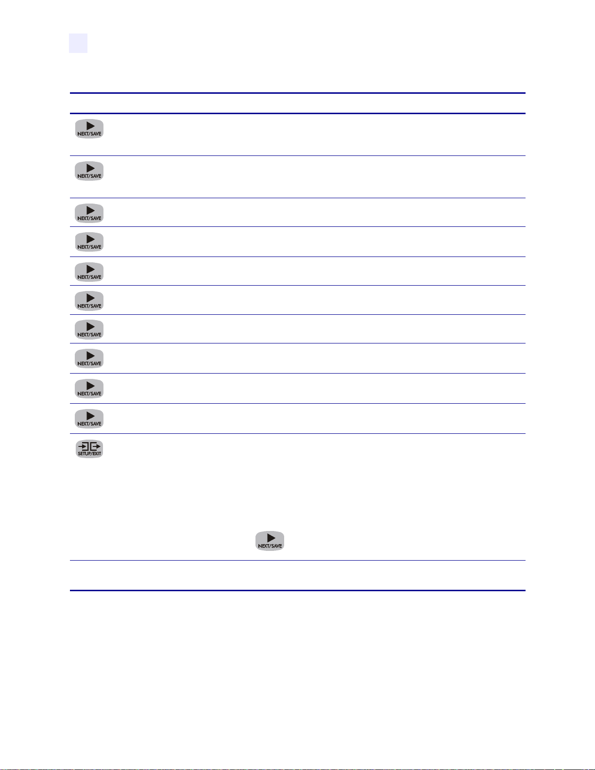
Table 4 • Configuring the Printer (Continued)
Press: LCD Shows: Action/Explanation:
SENSOR TYPE Press the oval keys to select web or mark sensing mode. If your media
does not have black marks on the back, leave your printer at the default
(web) setting.
PRINT METHOD Press the oval keys to select the method of printing you want to use:
direct thermal (no ribbon) or thermal transfer (using thermal transfer
media and ribbon).
PRINT WIDTH Press the oval keys to set the printer to the width of your media.
MAXIMUM
LENGTH
Press the oval keys to set the maximum print length. Select the value
closest to but not less than the length of label you are using.
LIST FONTS Press the right oval key to print a list of available fonts.
LIST BAR CODES Press the right oval key to print a list of available bar codes.
LIST IMAGES Press the right oval key to print a list of available images.
LIST FORMATS Press the right oval key to print a list of all formats currently stored in
the printer’s DRAM, optional EPROM, or on an optional memory card.
LIST SETUP Press the right oval key to print a list of the current printer configuration
settings.
LIST ALL Press the right oval key to print a list of fonts, bar codes, images,
formats, and the current print engine configuration settings.
SAVE CHANGES Press the oval keys to select:
PERMANENT: saves the changes when the power is turned off.
TEMPORARY: saves the changes until changed again or until power is
turned off.
CANCEL: cancels all changes since entering the Setup Mode.
LOAD DEFAULTS: loads factory default values for all parameters.
LOAD LAST SAVE: loads values from the last permanent save.
Press to accept a selection.
— PRINTER READY You have exited the Setup Mode and are now ready for normal printer
operation.
EN-10 23064L-001 R1 6/14/04 English
Page 13

Preventive Maintenance
Perform the following cleaning activities according to the schedule below. Refer to Figure 7.
Table 5 • Preventive Maintenance Schedule
Area Method Interval
Printhead (Figure 7-A) Solvent*† Direct Thermal Print Mode:
Platen Roller (Figure 7-B) Solvent*
Media Sensor (Figure 9-A and
Air blow
Figure 10-A)
Media Path (Figure 1) Solvent*
Ribbon Sensor (Figure 7-C) Air blow
Tear B a r (Figure 7-E) Solvent* As needed.
Label Available Sensor (Figure 7-D) Air blow Monthly.
* Use Zebra’s Preventative Maintenance kit, part number 47362, or a solution of 90% isopropyl alcohol and
10% deionized water.
Printhead and Platen Roller Cleaning
Inconsistent print quality such as voids in the bar code or graphics may indicate a dirty
printhead. For best results, perform the following cleaning procedure after each roll of ribbon.
After every roll of media (or 150 m of
fanfold media).
Thermal Transfer Print Mode:
After every roll of ribbon.
Clean after every roll (1500 ft or 450 m) of thermal transfer ribbon, after every roll (500 ft or
150 m) of direct thermal media, or when “CLEAN HEAD NOW” appears on the LCD.
Note • You do NOT need to turn off the power for this procedure. If you turn off the power, all
data stored in the printer’s temporary memory is lost. If power is removed from a 600 dpi
printer when cleaning the printhead, the “CLEAN HEAD NOW” warning shown on the LCD
will not disappear.
Caution • An improperly connected printhead data or power cable may cause the
printhead to generate excessive heat and/or a false HEAD COLD message to display
while the printhead is hot enough to cause severe burns. Allow the printhead to cool.
Electrostatic Discharge Caution • Observe proper electrostatic safety precautions when
handling any static-sensitive components such as circuit boards and printheads.
1. Open the printhead by moving the printhead lever to the open position.
2. Remove the media and ribbon from the print mechanism.
3. Use Zebra’s Preventative Maintenance kit, part number 47362, or a solution of 90%
isopropyl alcohol and 10% deionized water on an applicator. Wipe the printhead elements
(Figure 7-A) from end to end. (The printhead elements form the grayish/black strip just
behind the chrome strip.) Allow a few seconds for the solvent to evaporate.
4. Rotate the platen roller (Figure 7-B) and clean thoroughly with solvent.
English 23064L-001 R1 6/14/04 EN-11
Page 14
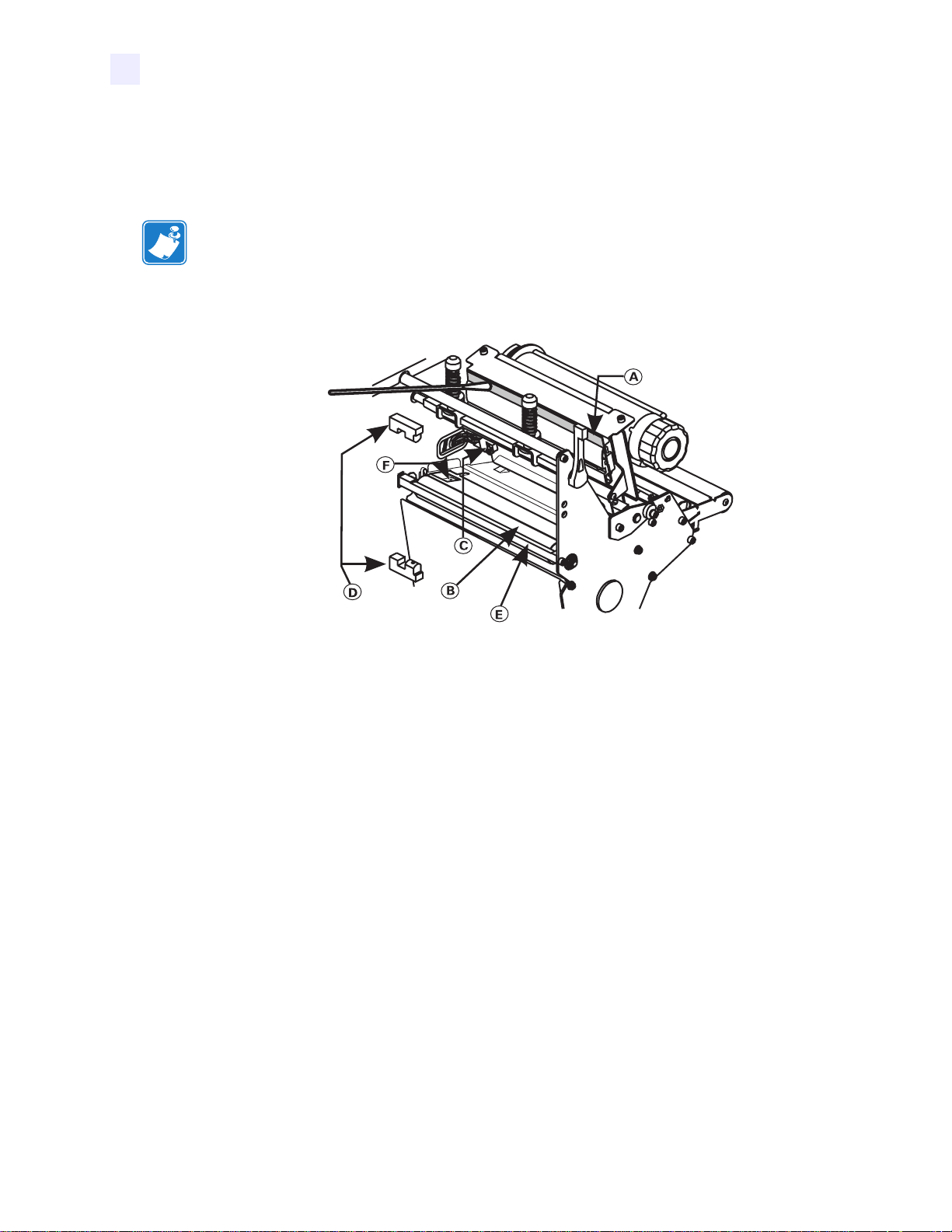
5. Brush/vacuum any paper lint and dust away from the rollers, the media sensor (Figure 9-A
and Figure 10-A), and the ribbon sensors (Figure 7-C).
6. Reload ribbon and/or media as necessary. Close the printhead by moving the lever to the
closed position. You may now continue printing.
Note • If print quality has not improved, try cleaning the printhead with Save-a-Printhead
cleaning film. This specially coated material removes contamination buildup without
damaging the printhead. Refer to the User Guide or call your authorized Zebra reseller or
distributor for more information.
Figure 7 • Printhead/Platen Roller Cleaning
Adjustments
Toggle Positioning
Position the toggle(s) to provide even pressure on the media by sliding them to the desired
location. If you are using narrow media and your printer has two toggles, you may position one
toggle over the center of the media and slide the other toggle out of the way (decrease the
pressure on the unused toggle).
Printhead Pressure Adjustment
Maximize printhead life by using the lowest pressure that provides the desired print quality.
Adjust the printhead pressure if printing is too light on one side or if thick media is used. Refer
to Figure 8.
1. Lower the darkness setting using the front panel controls and print some labels.
2. Loosen the locking nuts (Figure 8-A).
3. Some media types require higher pressure to print well. For these media, increase or
decrease pressure using the adjusting nuts (Figure 8-B) until the left and right edges of the
printed area are equally dark.
4. Increase the darkness to the desired level using the front panel controls.
EN-12 23064L-001 R1 6/14/04 English
Page 15

5. Tighten the locking nuts.
Figure 8 • Printhead Pressure Adjustment
Media Sensor Position Adjustments
The media sensor must be positioned so that it can detect the “web” between labels or a hole or
notch in the media.
The factory-set position should be sufficient for most applications. If not, perform the
appropriate adjustments.
Upper Media Sensor Adjustment
To adjust for the inside half of the media:
1. Remove the ribbon. Locate the upper media sensor (Figure 9-A).
2. Loosen the screw.
3. Slide the upper sensor along the slot until it is directly above the web, notch, or hole in the
media.
4. Tighten the screw.
Figure 9 • Upper Media Sensor
English 23064L-001 R1 6/14/04 EN-13
Page 16

To adjust for the outside half of the media:
5. Remove the ribbon. Locate the upper media sensor (Figure 9-A).
6. Remove the screw.
7. Lift the upper media sensor assembly and move the sensor and the wire cover to the
outside half. Carefully pull the wires through the cable tie. You may need to set aside the
sensor wire cover if the adjustment is too far to the outside.
8. Replace and tighten the screw.
9. Make sure the wires are routed back into the groove of the media sensor bracket.
Lower Media Sensor Adjustment
1. Locate the lower media sensor assembly (Figure 10-A) under the rear idler roller. (It is a
spring clip holding a circuit board.)
2. Slide the sensor until the two brass-colored infrared emitters are under the upper media
sensor. Gently pull wires out as needed (wires should have a little slack).
Note • If the sensor is being moved inward and a large loop of wire develops, remove the
cover from the electronics side of the printer and gently pull the wires through. Clamp the
wires so that they do not rub any drive belts.
Figure 10 • Lower Media Sensor
EN-14 23064L-001 R1 6/14/04 English
Page 17

Zebra RXiIIIPlus
Guía de Referencia Rápida
Esta guía de seguridad y referencia rápida de la impresora Zebra RXiIIIPlus contiene información
básica sobre cómo instalar y operar la impresora así como algunos ajustes sencillos que puede
llevar a cabo el operador. Sin embargo, esta guía no es completa.
Póngase en contacto con su distribuidor para obtener información adicional sobre las impresoras
Zebra RXiIIIPlus:
• Guía del usuario (No. de pieza 23062-001/ 23063L-001)
• Guía de programación del ZPL II (No. de pieza 45541L / 45542L)
• Manual de mantenimiento (No. de pieza 13185L / 48152L)
Contenidos
Especificaciones . . . . . . . . . . . . . . . . . . . . . . . . . . . . . . . . . . . . . . . . . . . . . . 2
Carga de papel y de la cinta . . . . . . . . . . . . . . . . . . . . . . . . . . . . . . . . . . . . . 3
Controles del operador . . . . . . . . . . . . . . . . . . . . . . . . . . . . . . . . . . . . . . . . . 7
Calibración. . . . . . . . . . . . . . . . . . . . . . . . . . . . . . . . . . . . . . . . . . . . . . . . . . . 8
Configuración . . . . . . . . . . . . . . . . . . . . . . . . . . . . . . . . . . . . . . . . . . . . . . . . 9
Mantenimiento preventivo . . . . . . . . . . . . . . . . . . . . . . . . . . . . . . . . . . . . . . 12
Ajustes. . . . . . . . . . . . . . . . . . . . . . . . . . . . . . . . . . . . . . . . . . . . . . . . . . . . . 14
Español 23064L-001 R1 6/14/04 ES-1
Page 18

Especificaciones
Eléctricas
90–264 VCA; 48–62 Hz
Tabla 1 • Consumo inicial de potencia
Impresión 100% negra a 6 pulgadas por segundo
R110XiIIIPlus
Máxima
Reserva
Gama medioambiental
Operación
• 5°C a 40°C (41°F a 104°F)
• 20% a 85% de humedad relativa sin condensación
Almacenamiento
• –40°C a 60°C (–40°F a 140°F)
• 5% a 85% de humedad relativa sin condensación
Fusibles
La impresora R110XiIIIPlus no tiene un fusible reemplazable por el usuario.
250W
25W
Cintas y desgaste de la cabeza de impresión
En el caso del método de impresión por transferencia térmica, ponga la cinta antes de realizar
la CALIBRACIÓN. No ponga la cinta si se va a usar la impresora en la modalidad térmica
directa. Las cintas usadas en la impresora deben ser tan anchas o más anchas que el papel. Las
cintas Zebra disponen de una superficie de refuerzo suave que protege la cabeza contra la
abrasión del papel. Si la cinta es más estrecha que el papel, habrá zonas de la cabeza que
estarán sin proteger y sujetas a un desgaste prematuro.
ES-2 23064L-001 R1 6/14/04 Español
Page 19

Carga de papel y de la cinta
Carga de papel
Figura 1 • Carga del papel—Componentes de la impresora
Figura 2 • Modalidades de carga del papel
Español 23064L-001 R1 6/14/04 ES-3
Page 20

Carga del rollo de papel en la modalidad de arrancado (Figura 2-A)
1. Desde el panel delantero, seleccione la modalidad de impresión adecuada.
2. Coloque el rollo de papel (Figura 1-E) en el soporte suspendido de papel (Figura 1-F) o en
el huso de alimentación optativo.
3. Abra la cabeza de impresión moviendo la palanca ubicada en el conjunto de cabeza de
impresión superior a la posición abierta (Figura 1-A).
4. Afloje el tornillo de mariposa de la guía del papel (Figura 8-M) y coloque la guía lo más
lejos posible del bastidor de la impresora.
5. Pase el papel por debajo del conjunto de brazo oscilante (Figura 1-P), por debajo del
rodillo inferior (Figura 1-L), entre la placa de la guía superior del papel y la guía principal
del papel, por debajo de la cabeza de impresión y por encima de la platina (Figura 1-J).
6. Ajuste la posición de la guía del papel (Figura 1-M) hasta que ésta toque justo el borde
exterior del papel sin hacer que se combe. Asegúrese de que sea paralela al borde del
papel, y después apriete el tornillo de mariposa.
7. Cierre la cabeza de impresión moviendo la palanca ubicada en el conjunto de cabeza de
impresión superior a la posición cerrada (Figura 1-B).
8. IMPORTANTE: Efectúe los ajustes de posición del sensor de papel encontrados en la
página 15.
Carga del papel plegado (Figura 3)
El papel plegado puede colocarse en el fondo del compartimiento del papel, en el recipiente de
alimentación optativo de papel plegado o fuera de la impresora con acceso por la parte de
abajo o atrás de la misma.
Ajuste el tornillo de mariposa de la guía del papel (Figura 1-M) para impedir que el papel se
desvíe hacia los lados. Asegúrese de que sea paralelo al borde del papel.
Figura 3 • Carga del papel plegado
ES-4 23064L-001 R1 6/14/04 Español
Page 21

Carga de la cinta
Consulte la Figura 4. Al cargar la cinta, asegúrese de que el tubo de enrollado de la cinta esté
metido hacia arriba contra el tope del huso de alimentación de la cinta (Figura 11-D). No use
una cinta que sea más estrecha que el papel.
1. Alinee los segmentos del rodillo de alimentación de la cinta (Figura 4).
2. Coloque el rollo de cinta en el huso de alimentación de la cinta (Figura 4-D).
3. Haga una guía para la cinta. Arranque una tira de papel (con etiquetas) de
aproximadamente 15 a 30 cm de largo. Pegue la mitad de esta etiqueta en el extremo de la
tira y la otra mitad en el extremo de la cinta. Esto equivale a una guía de la cinta.
4. Abra la cabeza (Figura 11-A) de impresión y pase la guía de la cinta y la cinta conectada
por el mecanismo de impresión, por debajo del rodillo superior (Figura 4-K), y pasada la
platina (Figura 4-J).
5. Antes de enrollar la cinta alrededor del rodillo de tensado de la cinta, asegúrese de que la
flecha de la perilla esté alineada con la muesca (vea el recuadro, Figura 5).
6. Coloque la cinta con la guía alrededor del rodillo de tensado de la cinta (Figura 4-C) y
enróllela varias veces hacia la izquierda.
7. Cierre la cabeza de impresión (Figura 4-B).
Figura 4 • Carga de la cinta
Español 23064L-001 R1 6/14/04 ES-5
Page 22

Cómo quitar la cinta usada
Consulte la Figura 5.
1. Rompa la cinta por un lugar cerca del rodillo de tensado de la cinta (Figura 5-A).
2. Gire la perilla (Figura 5-B) hacia la derecha a la vez que sujeta el rodillo de tensado de la
cinta hasta que se pare. Esto hará que las barras de desprendimiento de la cinta pivoten
hacia abajo (Figura 5-C), disminuyendo la “tirantez” de la cinta enrollada.
3. Saque la cinta del rodillo de tensado deslizándola hacia afuera. Una vez que haya quitado
la cinta usada, asegúrese de que la flecha de la perilla esté alineada con la muesca del
rodillo de tensado de la cinta (vea el recuadro).
4. Quite el tubo vacío del huso de alimentación de la cinta.
Figura 5 • Cómo quitar la cinta
ES-6 23064L-001 R1 6/14/04 Español
Page 23

Controles del operador
Botones del panel delantero
Tabla 2 • Botones del panel delantero
Botones
Indicación
Pulse para entrar/salir de la modalidad de Pausa. Figura 6 • Panel
delantero
Alimenta una etiqueta en blanco cada vez que se pulsa el botón.
(Activo solamente en la modalidad de Pausa). Pulse una vez para
cancelar la impresión del lote de etiquetas en curso. Para limpiar
completamente la memoria intermedia, pulse el botón y
manténgalo pulsado hasta que se apague la luz de DATOS.
(Activo solamente en la modalidad de Pausa). Pulse una vez para
volver a calibrar los sensores del papel y de la cinta a fin de
asegurarse de que el papel tenga la longitud adecuada y ajustar el
tipo de papel (continuo o discontinuo).
Estos botones se usan en el proceso de configuración.
Luces del panel delantero
La Tabla 3 describe la operación de las luces del panel delantero.
Nota • La luz destellará si se presenta una condición de operación que haga que la lista esté
encendida constantemente y otra que haga que la misma luz destelle al mismo tiempo.
Tabla 3 • Luces del panel delantero
Luz Estado Indicación
TAKE LABEL
(tomar etiqueta)
ERROR Apagada Operación normal—sin errores de la impresora.
Español 23064L-001 R1 6/14/04 ES-7
Apagada Operación normal.
Intermitente (Modalidad de pelado solamente) La etiqueta está disponible. La
impresión hace una pausa hasta que se quite la etiqueta.
Intermitente Existe un error de la impresora. Compruebe la pantalla para obtener más
información.
Page 24

Tabla 3 • Luces del panel delantero
Luz Estado Indicación
CHECK RIBBON
(comprobar cinta)
Apagada Operación normal—la cinta está bien cargada.
Encendida No se ha cargado la cinta (la impresora está en la modalidad de
transferencia térmica). El panel delantero muestra el mensaje de error.
PAPER OUT (si n
papel)
Apagada Operación normal—el papel está bien cargado.
Encendida La impresora ha detenido todas las operaciones de impresión. La
impresora ha hecho una pausa, la pantalla muestra un mesaje de error y
la luz PAUSE está encendida.
PAUSE (pausa) Apagada Operación normal.
Encendida La impresora ha detenido todas las operaciones de impresión.
Se produjo una de las cosas siguientes: se pulsó , se incluyó un
comando de pausa en el formato de la etiqueta o el verificador en línea
detectó un error durante el funcionamiento.
DATA
(datos)
Apagada Operación normal—no se reciben ni se procesan datos.
Encendida Procesamiento o impresión de datos—no se reciben datos.
Intermitente La impresora está recibiendo datos. La intermitencia se hace más lenta
cuando la impresora no puede aceptar más datos, pero vuelve a su
cadencia normal una vez que se vuelven a recibir los datos.
Calibración
Después de haber instalado bien el papel y la cinta, encienda la impresora. La impresora
realizará un procedimiento de autocomprobación (POST). Una vez terminado, la pantalla de
cristal líquido (LCD) indicará “IMPRESORA LISTA”.
A continuación la impresora se calibra automáticamente. Durante este proceso, la impresora
alimenta varias etiquetas para determinar automáticamente los ajustes del sensor de papel y de
la cinta. Este proceso se repita siempre que se abre la cabeza de impresión.
Importante • Si está apagada la autocalibración, realice el procedimiento de calibración de
papel y cinta del menú del LCD siempre que se instale un tipo diferente de papel o cinta.
1. Pulse .
2. Pulse .
3. Pulse .
La impresora alimenta varias etiquetas.
ES-8 23064L-001 R1 6/14/04 Español
Page 25

Configuración
Una vez terminada la calibración, podrá fijar los parámetros de la impresora para su aplicación
usando la pantalla del panel delantero y los cinco botones ubicados directamente debajo del
mismo.
El procedimiento de configuración de la Tabla 4 contiene la información necesaria para
preparar la impresora y ponerla en funcionamiento, pero no es completo. Consulte la guía del
usuario para obtener información adicional.
Introduzca la modalidad de configuración pulsando una vez que aparezca
IMPRESORA LISTA en la pantalla.
Siga el procedimiento de la Tab la 4. Podrá salir de la modalidad de configuración en cualquier
momento pulsando (siga las instrucciones del final de la tabla).
• La presencia de un asterisco (*) en la esquina superior izquierda del LCD indica que se ha
cambiado este ajuste y que es diferente del que está almacenado en la memoria.
• Para cambiar un parámetro, use los botones ovalados negros izquierdo y derecho justo
debajo del LCD:
Aumenta el valor, contesta “sí”, indica “activado” o muestra la siguiente selección.
Disminuye el valor, contesta “no”, indica “desactivado” o muestra la selección anterior.
Tabla 4 • Configuración
Pulse: LCD muestra: Acción/Explicación:
— IMPRESORA LISTA Operación normal de la impresora.
CONTRASTE Pulse los botones ovalados para cambiar el contraste de la impresión.
PRECAUCIÓN: Fije el contraste en el valor más bajo que produzca
una buena calidad de impresión. Si este ajuste es muy alto, se pueden
producir borrones de tinta o se puede perforar la cinta por quemadura.
Para cambiar el idioma del LCD (omita esto si el LCD ya está en el idioma escogido):
IDIOMA Pulse los botones ovalados para cambiar el idioma del texto del LCD.
CONTRASTE Pulse los botones ovalados para cambiar el contraste de la impresión.
PRECAUCIÓN: Fije el contraste en el valor más bajo que produzca
una buena calidad de impresión. Si este ajuste es muy alto se pueden
producir borrones de tinta o se puede perforar la cinta por quemadura.
VELOC DE IMPRES. Pulse los botones para aumentar o disminuir la velocidad de la
impresión.
ARRANCADO Pulse los botones ovalados para cambiar la posición del papel sobre la
barra de arrancado después de la impresión. Efectúe este ajuste si las
etiquetas se arrancan por el lugar equivocado.
MODALIDAD
IMPRES.
Pulse los botones ovalados para seleccionar la modalidad de arrancado,
pelado, corte o rebobinado. Asegúrese de escoger una modalidad que
esté disponible para su impresora específica (ya que algunas de estas
modalidades requieren opciones especiales).
Español 23064L-001 R1 6/14/04 ES-9
Page 26

Tabla 4 • Configuración
Pulse: LCD muestra: Acción/Explicación:
TIPO DE PAPEL Pulse los botones ovalados para seleccionar si el tipo de papel es
continuo o discontinuo. Discontinuo: la impresora determina
automáticamente la longitud de la etiqueta detectando la muesca, la
distancia de separación, el papel sin etiquetas o las marcas negras entre
etiquetas. Continuo: debe incluir una instrucción de la longitud de la
etiqueta en el formato de la etiqueta (^LLxxxx si está usando ZPL o
ZPL II).
TIPO DE SENSOR Pulse los botones ovalados para seleccionar la modalidad de papel sin
etiquetas o detección de marcas. Si el papel no tiene marcas negras en
el reverso, deje la impresora en el ajuste implícito (papel sin etiquetas).
MÉTODO IMPRES. Pulse los botones ovalados para seleccionar el método de impresión
deseado: térmico directo (sin cinta) o transferencia térmica (usando el
papel y la cinta de transferencia térmica).
ANCHO IMPRES. Pulse las teclas ovaladas para fijar el motor de impresión al ancho de
impresión al ancho del papel.
LONGITUD MÁXIMA Pulse los botones ovalados para fijar la longitud máxima de impresión.
Seleccione el valor más aproximado por exceso a la longitud del papel
que esté usando, pero no por defecto.
LISTAR FUENTES Pulse el botón ovalado derecho para imprimir una lista de los juegos de
caracteres disponibles.
LISTAR C. BARRAS Pulse el botón ovalado derecho para imprimir una lista de los códigos
de barras disponibles.
LISTA IMÁGENES Pulse el botón ovalado para imprimir una lista de imágenes
disponibles.
LISTAR FORMATOS Pulse el botón ovalado derecho para imprimir una lista de todos los
formatos almacenados actualmente en la memoria DRAM de la
impresora, en la memoria EPROM opcional o en una tarjeta de
memoria opcional.
LISTAR CONFIG. Pulse el botón ovalado derecho para imprimir una lista de los ajustes
actuales de configuración de la impresora.
listar todo Pulse la tecla ovalada derecha para imprimir una lista de fuentes,
códigos de barras, imágenes, formatos y ajustes de configuración en
curso del motor de impresión.
ES-10 23064L-001 R1 6/14/04 Español
Page 27

Tabla 4 • Configuración
Pulse: LCD muestra: Acción/Explicación:
GUARDAR CAMBIOS Pulse los botones ovalados para seleccionar:
PERMANENTE: guarda los cambios cuando se apaga la impresora.
TEMPORAL: guarda los cambios hasta que se vuelvan a cambiar o
hasta que se apague la impresora.
CANCELAR: cancela todos los cambios desde que se pasó a la
modalidad de configuración.
CARGAR ORIG: carga los valores implícitos de fábrica para todos los
parámetros.
CARGAR ÚLTIMO: carga los valores de la última vez que se
guardaron de forma permanente.
Pulse para aceptar una selección.
— IMPRESORA LISTA Acaba de salir de la modalidad de configuración y está listo para la
operación normal de la impresora.
Español 23064L-001 R1 6/14/04 ES-11
Page 28

Mantenimiento preventivo
Efectúe las siguientes actividades de limpieza según el plan siguiente. Consulte la Figura 7.
Tabla 5 • Plan de limpieza
Área Método Intervalo
Cabeza de impresión
(Figura 7-A)
Platina (Figura 7-B) Disolvente*
Sensor de papel (Figura 9-A
y Figura 10-A)
Trayectoria del papel
(Figura 1)
Sensor de la cinta
(Figura 7-C)
Barra de arrancado
(Figura 7-E)
Sensor de etiquetas
disponible (Figura 7-D)
* Utilice el equipo de mantenimiento preventivo (número de pieza 47362) o una solución formada por un 90%
de alcohol isopropílico y un 10% de agua desionizada.
Disolvente*† Modalidad de impresión directa térmica:
Después de cada rollo de papel (o 150 m de papel
plegado).
Modalidad de impresión de transferencia térmica:
Aire comprimido
Disolvente*
Aire comprimido
Disolvente* Según sea necesario.
Aire comprimido Mensualmente
Después de cada rollo de cinta.
Procedimiento para la limpieza de la cabeza de impresión y la platina
La falta de uniformidad en la calidad de impresión tales como espacios vacíos en el código de
barras o gráficos puede indicar una cabeza de impresión sucia. Para obtener los mejores
resultados, efectúe el siguiente procedimiento de limpieza después de cada rollo de cinta.
Limpie después de cada rollo (450 metros) de cinta de transferencia térmica, después de cada
rollo (150 metros) de papel térmico directo o cuando aparezca la advertencia “LIMPIE
CABEZA YA” en el LCD.
Nota • NO es necesario desconectar la corriente para este procedimiento. Si se desconecta, se
pierden todos los datos almacenados en la memoria temporal de la impresora. Si se desconecta
la corriente de una impresora de 600 dpi al limpiar la cabeza de impresión, no desaparecerá la
advertencia LIMPIE CABEZA YA en el LCD.
Atención • La cabeza de impresión puede estar caliente y quemar la piel al descubierto.
Atención: riesgo de descarga electrostática • Cumpla con todas las precauciones de
seguridad electrostática al manejar componentes sensibles a la electricidad estática tales
como placas de circuito impreso y cabezas de impresión.
ES-12 23064L-001 R1 6/14/04 Español
Page 29

1. Abra la cabeza de impresión moviendo la palanca de la misma a la posición abierta.
2. Quite el papel y la cinta del mecanismo de impresión.
3. Utilice el equipo de mantenimiento preventivo de Zebra (número de pieza 47362) o una
solución formada por un 90% de alcohol isopropílico y un 10% de agua desionizada en un
aplicador. Limpie los elementos de la cabeza de impresión (Figura 7-A) de un extremo al
otro. (Los elementos de la cabeza de impresión forman la tira grisácea/negra justo detrás
de la tira cromada). Deje que el disolvente se evapore durante unos segundos.
4. Gire la platina (Figura 7-B) y limpie completamente con disolvente.
5. Cepille/Aspire las fibras de papel y el polvo de los rodillos, sensor del papel (Figura 9-A y
Figura 10-A) y sensores de la cinta (Figura 7-C).
6. Vuelva a cargar la cinta o el papel según sea necesario. Cierre la cabeza de impresión
moviendo la palanca a la posición cerrada. Ahora se puede continuar la impresión.
Nota • Si no se ha mejorado la calidad de la impresión, trate de limpiar la cabeza de
impresión con una película de limpieza Save-a-Printhead. Este material especialmente
revestido elimina la contaminación acumulada sin dañar la cabeza de impresión. Consulte
la Guía del usuario o llame a su revendedor o distribuidor autorizado Zebra para obtener
información adicional.
Figura 7 • Limpieza de la cabeza de impresión/platina
Español 23064L-001 R1 6/14/04 ES-13
Page 30

Ajustes
Colocación de los fiadores
Coloque los fiadores de modo que ejerzan una presión uniforme sobre el papel deslizándolos
hasta la posición deseada. Si está usando papel estrecho y la impresora tiene dos fiadores,
puede colocar un fiador sobre el centro del papel y apartar el otro fiador deslizándolo hacia
afuera (reduzca la presión en el fiador que no use).
Ajuste de presión de la cabeza de impresión
Prolongue al máximo la duración de la cabeza de impresión usando la mínima presión que
produzca la calidad de impresión deseada. Ajuste la presión de la cabeza de impresión si la
impresión es demasiado clara por un lado o si se usa papel grueso. Consulte la Figura 8.
1. Disminuya el ajuste del contraste e imprima algunas etiquetas.
2. Afloje las contratuercas (Figura 8-A).
3. Algunos tipos de papel necesitan una mayor presión para imprimirse bien. Para estos
papeles, aumente y disminuya la presión usando las tuercas de ajuste (Figura 8-B) hasta
que los bordes izquierdo y derecho de la zona de impresión están igual de oscuros.
4. Aumente el contraste hasta el nivel deseado usando los controles del panel delantero.
5. Apriete las contratuercas.
Figura 8 • Ajuste de presión de la cabeza de impresión
ES-14 23064L-001 R1 6/14/04 Español
Page 31

Ajustes de posición del sensor de papel
El sensor de papel debe colocarse de modo que pueda detectar el “papel” entre etiquetas o un
agujero o muesca en el papel.
La posición fijada en fábrica debe ser suficiente para la mayoría de las aplicaciones. Si no es
así, realice los ajustes apropiados.
Ajuste del sensor de papel superior
Para ajustar la mitad interior del papel:
1. Quite la cinta. Localice el sensor superior del papel (Figura 9-A).
2. Afloje el tornillo.
3. Deslice el sensor superior a lo largo de la ranura hasta que esté directamente encima del
papel sin etiquetas, muesca o agujero del papel.
4. Apriete el tornillo.
Figura 9 • Sensor superior del papel
Para ajustar la mitad exterior del papel:
5. Quite la cinta. Localice el sensor superior del papel (Figura 9-A).
6. Quite el tornillo.
7. Levante el conjunto de sensor superior del papel y mueva el sensor y la tapa del cable a la
mitad exterior. Tire con cuidado de los cables por la ligadura del cable. Tal vez tenga que
poner a un lado la tapa del cable del sensor si el ajuste está muy hacia el exterior.
8. Coloque y apriete el tornillo.
9. Asegúrese de volver a poner los cables dentro de la ranura del soporte del sensor del
papel.
Español 23064L-001 R1 6/14/04 ES-15
Page 32

Ajuste del sensor inferior del papel
1. Localice el conjunto de sensor inferior del papel (Figura 10-A) debajo del rodillo loco
trasero. (Es una presilla de resorte que sujeta un tablero de circuitos).
2. Deslice el sensor hasta que los dos emisores infrarrojos bronceados estén debajo del
sensor superior del papel. Tire suavemente de los cables hacia afuera según sea necesario
(los cables deben estar un poco destensados).
Nota • Si el sensor se mueve hacia adentro y se forma un círculo grande de cable, quite la
tapa del lado de los componentes electrónicos de la impresora y tire suavemente de los
cables a través del mismo. Sujete los cables de modo que no rocen ninguna de las correas
impulsoras.
Figura 10 • Sensor inferior del papel
ES-16 23064L-001 R1 6/14/04 Español
Page 33

Zebra RXiIIIPlus
Guide de Référence Rapide
Ce Guide de sécurité et de référence rapide donne des informations de base sur l’installation et le
fonctionnement de l’imprimante, ainsi que sur certains réglages simples qui peuvent être effectués
par l’opérateur ; il ne prétend toutefois pas être exhaustif.
Des informations complémentaires sur les imprimantes Zebra RXiIIIPlus sont disponibles auprès
de votre distributeur :
• Guide d’utilisation (pièce n° 23062-001/ 23063L-001)
• ZPL II Programming Guide (pièce n° 45541L / 45542L)
• Maintenance Manual (pièce n° 13185L / 48152L)
Table des Matières
Spécifications. . . . . . . . . . . . . . . . . . . . . . . . . . . . . . . . . . . . . . . . . . . . . . . . . 2
Chargement du papier et du ruban . . . . . . . . . . . . . . . . . . . . . . . . . . . . . . . . 3
Commandes . . . . . . . . . . . . . . . . . . . . . . . . . . . . . . . . . . . . . . . . . . . . . . . . . 7
Calibrage . . . . . . . . . . . . . . . . . . . . . . . . . . . . . . . . . . . . . . . . . . . . . . . . . . . . 8
Configuration . . . . . . . . . . . . . . . . . . . . . . . . . . . . . . . . . . . . . . . . . . . . . . . . . 9
Entretien préventif . . . . . . . . . . . . . . . . . . . . . . . . . . . . . . . . . . . . . . . . . . . . 12
Réglages . . . . . . . . . . . . . . . . . . . . . . . . . . . . . . . . . . . . . . . . . . . . . . . . . . . 14
Français 23064L-001 R1 6/14/04 FR-1
Page 34

Spécifications
Spécifications électriques
90 – 264 V ; 48 – 62 Hz
Tableau 1 • Consommation initiale de courant
Iimpression 100% noire à 6 instructions/sec
R110XiIIIPlus
Maximum
Au repos
Cadre d’utilisation
Fonctionnement
• 5 à 40°C
• 20 à 85% d’humidité relative sans condensation
Entreposage
• −40 à 60°C
• 5 à 85% d’humidité relative sans condensation
Fusibles
Le modèle R110XiIIIPlus n'a pas de fusible remplaçable par l'utilisateur.
250W
25W
Rubans et usure de la tête d’impression
En cas d’impression en mode transfert thermique, charger un ruban avant d’effectuer le
CALIBRAGE. Ne pas charger un ruban si l’imprimante doit fonctionner en mode
d’impression thermique directe. Les rubans utilisés par l’imprimante doivent être au moins
aussi larges que le papier. Voir la Figure 1. Les rubans Zebra offrent une surface dorsale
extrêmement lisse qui protège la tête d’une abrasion causée par le support d’impression. Si le
ruban est plus étroit que ce dernier, la tête sera partiellement exposée et sujette à usure
prématurée.
FR-2 23064L-001 R1 6/14/04 Français
Page 35

Chargement du papier et du ruban
Chargement du papier
Figure 1 • Chargement du papier—Éléments de l’imprimante
Figure 2 • Modes de chargement du papier
Français 23064L-001 R1 6/14/04 FR-3
Page 36

Chargement du papier en mode déchirement (Figure 2-A)
1. Sur le panneau avant, sélectionnez le mode d'impression approprié.
2. Placez le rouleau de papier (Figure 1-E) sur le porte-rouleau (Figure 8-F) ou sur l’axe
prévu en option à cet effet.
3. Ouvrez la tête d’impression en plaçant le levier qui se trouve sur l’ensemble d’impression
supérieur en position ouverte (Figure 1-A).
4. Desserrez la vis à oreilles du guide de papier (Figure 1-M) et placez celui-ci aussi loin que
possible du bâti de l’imprimante.
5. Enfilez le papier sous l’arbre libre (Figure 1-P), sous le rouleau inférieur (Figure 1-L),
entre le plateau supérieur de guidage de papier et le guide principal de papier, sous la tête
d’impression et par-dessus le rouleau d’impression (Figure 1-J).
6. Réglez la position du guide de papier (Figure 8-M) jusqu’à ce qu’il touche juste le bord
extérieur du papier sans provoquer la déformation de celui-ci. Assurez-vous qu’il est
parallèle au bord du papier, puis resserrez la vis à oreilles.
7. Refermez la tête d’impression en plaçant le levier qui se trouve sur l’ensemble
d’impression supérieur en position fermée (Figure 1-B).
8. IMPORTANT : procédez aux réglages de la position des cellules papier décrits à la page
15.
Chargement de papier à pliage paravent (Figure 3)
Le papier à pliage paravent peut être placé à la partie inférieure du compartiment de papier,
dans le bac d’alimentation en papier à pliage paravent, ou à l’extérieur de l’imprimante avec
accès par le dessous ou l’arrière.
Réglez la vis à oreilles du guide de papier (Figure 1-M) pour empêcher ce dernier de dériver ;
veillez à ce que le guide soit parallèle au bord du papier.
Figure 3 • Chargement d’un papier à pliage paravent
FR-4 23064L-001 R1 6/14/04 Français
Page 37

Chargement du ruban
Voi r l a Figure 4. Lorsque vous chargez le ruban, assurez-vous que que son noyau est poussé
vers le haut, contre la butée qui se trouve sur l’axe du rouleau de ruban (Figure 4-D). N’utilisez
pas un ruban plus étroit que le support d’impression.
1. Alignez les segments de l’axe du rouleau de ruban (Figure 4).
2. Placez le rouleau de ruban sur l’axe prévu à cet effet (Figure 4-D).
3. Préparez une amorce de ruban. Déchirez une bande de support (étiquettes et dorsal)
d’environ 15 à 30 cm de long. Décollez une étiquette de cette bande. Collez la moitié de
cette étiquette sur l’extémité de la bande et l’autre moitié à l’extrémité du ruban. Cela sert
d’amorce de ruban.
4. Ouvrez la tête d’impression (Figure 4-A), puis enfilez l’amorce et le ruban qui la suit dans
le mécanisme d’impression, sous le rouleau supérieur (Figure 4-K) et au-delà du contrerouleau (Figure 4-J).
5. Avant d’enrouler le ruban autour de son mandrin récupérateur, assurez-vous que la flèche
qui se trouve sur le bouton s’aligne sur l’encoche dentelée (voir encart, Figure 5).
6. Enroulez le ruban avec amorce de plusieurs tours dans le sens antihoraire autour de son
mandrin récupérateur (Figure 4-C).
7. Refermez la tête d’impression (Figure 4-B).
Figure 4 • Chargement du ruban
Français 23064L-001 R1 6/14/04 FR-5
Page 38

Retrait d’un ruban usagé
Voi r l a Figure 5.
1. Coupez le ruban près du mandrin récupérateur de ruban (Figure 4-A).
2. Tout en tenant le mandrin récupérateur de ruban, tournez le bouton (Figure 4-B) à fond
dans le sens horaire. Cela provoque le pivotement vers le bas (Figure 4-C) des barres de
libération du ruban, allégeant ainsi la « prise » du mandrin sur le ruban enroulé.
3. Glissez le ruban hors de son mandrin récupérateur. Une fois que vous avez enlevé le ruban
usagé, assurez-vous que la flèche qui se trouve sur le bouton s’aligne sur l’encoche
dentelée (voir encart).
4. Enlevez le noyau vide de l’axe du rouleau de ruban.
Figure 5 • Retrait du ruban
FR-6 23064L-001 R1 6/14/04 Français
Page 39

Commandes
Touches du panneau avant
Tableau 2 • Touches du panneau avant
Button/Key Description
Appuyez sur cette touche pour passer en mode pause ou en sortir. Figure 6 • Commandes
Fait avancer une étiquette chaque fois que vous appuyez sur la
touche.
(Active en mode pause uniquement.) Appuyez une fois sur la
touche pour annuler l’impression du lot d’étiquettes en cours
d’impression. Pour vider entièrement le tampon, appuyez sur la
touche et maintenez-la enfoncée jusqu’à ce que le voyant DATA
(Données) s’éteigne.
(Active en mode pause uniquement.) Appuyez une fois sur la
touche pour recalibrer les détecteurs d’étiquettes et de ruban en
fonction de la longueur appropriée du support d’impression et
sélectionnez le type de support (continu ou non).
Ces touches sont utilisées pour la configuration.
Voyants du panneau avant
Le Table au 3 décrit le fonctionnement des voyants du panneau avant.
Remarque • si une condition de fonctionnement provoquant l’allumage constant d’un voyant
et une autre provoquant le clignotement de ce même voyant se produisent en même temps, le
voyant clignote.
Tableau 3 •
Voyant État Indication
TAKE LABEL
(Prise d’étiquette)
Eteint Fonctionnement normal.
Clignotant (Mode prédécollage uniquement) Une étiquette peut être décollée.
L’imprimante est en mode pause jusqu’à ce que l’étiquette soit décollée.
ERROR (Erreur) Eteint Fonctionnement normal. Aucune erreur d’imprimante détectée.
Clignotant Erreur d’imprimante. Consultez l’afficheur pour des informations
complémentaires.
Français 23064L-001 R1 6/14/04 FR-7
Page 40

Tableau 3 •
Voyant État Indication
CHECK RIBBON
(Vérifier ruban)
Eteint Fonctionnement normal. Ruban chargé correctement.
Allumé Aucun ruban chargé (imprimante en mode transfert thermique). Le
panneau avant affiche un message d’erreur.
PAP ER OUT (F in d e
papier)
Eteint Fonctionnement normal. Papier chargé correctement.
Allumé Absence de papier sous la cellule papier. L’imprimante est en mode pause,
un message d’erreur est affiché et le voyant PAUSE est allumé.
PAUSE Eteint Fonctionnement normal.
Allumé L’impression a complètement cessé. La touche a été actionnée,
une commande de pause a été incluse dans le format d’étiquettes, le
vérificateur en ligne a détecté une erreur, ou une erreur de durée
d’exécution a été détectée.
DATA (Données) Eteint Fonctionnement normal. Aucune donnée n’est reçue ni traitée.
Allumé Traitement de données ou impression en cours. Aucune donnée n’est
reçue.
Clignotant L’imprimante reçoit des données. La cadence de clignotement ralentit
lorsque l’imprimante ne peut plus recevoir de données, mais redevient
normale lorsque la réception reprend.
Calibrage
Une fois que le papier et le ruban sont installés correctement, mettez l’imprimante sous
tension. Elle effectue un autotest à la mise sous tension. Lorsque l’autotest est terminé, le
message « MACHINE PRÊTE » apparaît sur l’afficheur.
L’imprimante se calibre ensuite automatiquement. Au cours de cette opération, l’imprimante
fait avancer quelques étiquettes pour déterminer automatiquement la longueur d’étiquette et
les paramètres des cellules ruban. Cette opération se répète lors de chaque ouverture de la tête
d’impression.
Important • Si la fonction d’autocalibrage est désactivée, effectuez l’opération de calibrage du
ruban et du papier à partir du menu qui apparaît sur l’afficheur chaque fois qu’un type différent
de papier ou de ruban est chargé.
1. Appuyez sur .
2. Appuyez sur .
L’imprimante fait avancer plusieurs étiquettes.
3. Appuyez sur .
FR-8 23064L-001 R1 6/14/04 Français
Page 41

Configuration
Une fois le calibrage terminé, vous pouvez sélectionner des paramètres d’imprimante pour
votre application au moyen de l’affichage du panneau avant et des cinq touches qui se trouvent
juste en-dessous.
Le Table au 4, qui décrit l’opération de configuration, donne des informations dont vous aurez
besoin pour mettre votre imprimante en service, mais n’est pas exhaustif. Reportez-vous au
Guide d’utilisation pour des informations complémentaires.
Passez en mode configuration en appuyant sur lorsque le message MACHINE PRÊTE
s’affiche.
Procédez comme indiqué au Tableau 4. Vous pouvez à tout moment quitter le mode
configuration en appuyant sur (suivez les instructions données à la fin du tableau).
• La présence d’un astérisque (*) dans l’angle supérieure gauche de l’afficheur indique que
vous avez changé le paramètre stocké jusqu’alors en mémoire.
• Pour changer un paramètre, servez-vous des touches ovales noires gauche et droite qui se
trouvent juste en dessous de l’afficheur :
suivante.
précédente.
Augmente une valeur, répond « oui », indique « marche » ou affiche la sélection
Réduit une valeur, répond « non », indique « arrêt » ou affiche la sélection
Tableau 4 •
Appuyer sur : Message affiché : Action/explication :
— MACHINE PRÊTE Fonctionnement normal de l’imprimante.
CONTRASTE Appuyez sur les touches ovales pour modifier le contraste de
l’impression.
Attention • Réglez le contraste au niveau le plus bas permettant
d’obtenir une bonne qualité d’impression. S’il est réglé à un niveau
trop élevé, l’encre risque de maculer le papier et/ou de traverser le
ruban.
Pour changer la langue d’affichage sur le panneau avant (si l’affichage ne se fait pas déjà dans la langue de
votre choix) :
LANGAGE Appuyez sur les touches ovales pour changer la langue dans laquelle le
texte est affiché.
CONTRASTE Appuyez sur les touches ovales pour modifier le contraste de
l’impression.
Attention • Réglez le contraste au niveau le plus bas permettant
d’obtenir une bonne qualité d’impression. S’il est réglé à un niveau
trop élevé, l’encre risque de maculer le papier et/ou de traverser le
ruban.
VITESSE IMPRES. Appuyez sur les touches ovales pour accélérer ou ralentir l’impression.
Français 23064L-001 R1 6/14/04 FR-9
Page 42

Tableau 4 •
Appuyer sur : Message affiché : Action/explication :
DÉCHIREMENT Appuyez sur les touches ovales pour modifier la position du papier au-
dessus de la barre de déchirement après une impression. Veillez à choisir
des modes qui sont disponibles sur votre imprimante, dans la mesure où
ces modes exigent des options particulières.
MODE
D’IMPRESSION
Appuyez sur les touches ovales pour sélectionner le mode déchirement,
prédécollage, coupe ou réenroulage. Veillez à choisir des modes qui sont
disponibles sur votre imprimante, dans la mesure où ces modes exigent
des options particulières.
TYPE DE PAPIER Appuyez sur les touches ovales pour sélectionner un papier du type
continu ou non. Non continu : l’imprimante détermine automatiquement
la longueur d’étiquette en détectant l’encoche, l’intervalle, l’échenillage
ou la barre noire séparant les étiquettes. Continu : vous devez inclure
une instruction de longueur d’étiquette dans votre format d’étiquettes
(^LLxxxx si vous utilisez ZPL ou ZPL II).
TYPE DE
CELLULE
Appuyez sur les touches ovales pour sélectionner le mode de détection
par échenillage ou barre noire. Si le papier ne comporte pas de barres
noires au dos, laissez votre imprimante en mode de détection par défaut
(échenillage).
TYPE
IMPRESSION
Appuyez sur les touches ovales pour sélectionner la méthode
d’impression que vous voulez utiliser : thermique directe (sans ruban)
ou transfert thermique (avec papier à transfert thermique et ruban).
LARGEUR
IMPRES.
Appuyez sur les touches ovales pour ajuster l’imprimante à la largeur du
papier.
LONGUEUR MAXI Appuyez sur les touches ovales pour sélectionner la longueur maximum
d’impression. Sélectionner la valeur immédiatement supérieure à la
longueur d’étiquettes que vous utilisez.
LISTE DES
POLICES
LISTE CODE
BARRE
FR-10 23064L-001 R1 6/14/04 Français
Appuyez sur la touche ovale droite pour imprimer une liste des polices
disponibles.
Appuyez sur la touche ovale droite pour imprimer une liste des codes
barres disponibles.
Page 43

Tableau 4 •
Appuyer sur : Message affiché : Action/explication :
LISTE DES
IMAGES
LISTE DE
FORMAT
Appuyez sur la touche ovale droite pour imprimer une liste des images
disponibles.
Appuyez sur la touche ovale droite pour imprimer une liste de tous les
formats stockés dans la mémoire RAM dynamique de l’imprimante,
dans l’EPROM en option ou sur une carte mémoire en optiond.
LISTE CONFIG. Appuyez sur la touche ovale droite pour imprimer une liste des
paramètres de la configuration en vigueur de l’imprimante.
Liste complète Appuyez sur la touche ovale droite pour imprimer une liste des polices,
des codes barres, des images, des formats et des paramètres de la
configuration en vigueur du mécanisme d’impression.
SAUVEGARDE Appuyez sur les touches ovales pour sélectionner :
PERMANENTE : sauvegarde les changements apportés lorsque
l’imprimante est mise hors tension.
TEMPORAIRE : sauvegarde les changements apportés jusqu’aux
prochains changements ou jusqu’à ce que l’imprimante soit mise hors
tension.
ANNULÉE : annule tous les changements effectués depuis le passage
en mode configuration.
CONFIG DEFAUT : charge les valeurs sélectionnées par défaut à
l’usine pour tous les paramètres.
DERNIER SAUVE : charge les valeurs ayant fait l’objet de la dernière
sauvegarde permanente.
Appuyez sur pour accepter une sélection.
— MACHINE PRÊTE Vous avez quitté le mode configuration et êtes alors prêt à passer en
mode d’impression normal.
Français 23064L-001 R1 6/14/04 FR-11
Page 44

Entretien préventif
Effectuez les opérations de nettoyage suivantes conformément au programme ci-dessous. Voir
la Figure 7.
Tableau 5 •
Zone Méthode Intervalle
Tête d’impression (Figure 7-A) Solvant* † Mode d’impression thermique direct :
Contre-rouleau (Figure 7-B) Solvant*
Cellule papier (Figure 9-A et Figure 10-A) Soufflage d’air
Après chaque rouleau de papier (ou tous les
150 m de papier à pliage paravent).
Passage de papier (Figure 1) Solvant*
Cellule ruban (Figure 7-C) Soufflage d’air
Barre de déchirement (Figure 7-E) Solvant* Selon le besoin.
Cellule étiquette disponible (Figure 7-D) Soufflage d’air Tous les mois
* Utilisez le kit d'entretien préventif de Zebra, pièce n° 47362, ou une solution à 90 % d'alcool isopropylique et
10 % d'eau désionisée.
Mode d’impression à transfert thermique :
Après chaque rouleau de ruban.
Nettoyage de la tête d’impression et du contre-rouleau
Une qualité d’impression irrégulière, se manifestant par exemple par la présence de vides dans
le code barres ou le graphisme, peut indiquer que la tête d’impression est encrassée. Pour
obtenir les meilleurs résultats, effectuez l’opération de nettoyage suivante après chaque
rouleau de ruban.
Nettoyez après chaque rouleau (450 m) de ruban à transfert thermique, après chaque rouleau
(150 m) de papier thermique direct, ou lorsque l'avertissement « NETTOYEZ LA TÊTE »
apparaît sur l'afficheur.
Remarque • Il N'est PAS nécessaire de mettre l'imprimante hors tension pour cette procédure.
Si vous la mettez hors tension, toutes les données stockées dans la mémoire temporaire de
l'imprimante seront perdues. Si une imprimante à 600 ppp est mise hors tension lors du
nettoyage de la tête d’impression, l’avertissement « NETTOYEZ LA TÊTE » ne disparaît pas
de l’afficheur.
Attention • La tête d’impression risque d’être très chaude et peut brûler la peau nue.
Attention : Risque de Décharge Électrostatique • Observez les précautions de sécurité
électrostatique appropriées lors de la manipulation de tout composant sensible à
l'électricité statique, par exemple les cartes de circuits imprimés et les têtes d'impression.
1. Ouvrez la tête d’impression en plaçant son levier en position d’ouverture.
2. Retirez le papier et le ruban du mécanisme d’impression.
FR-12 23064L-001 R1 6/14/04 Français
Page 45

3. Utilisez le kit d'entretien préventif de Zebra, pièce n° 47362, ou une solution à 90 %
d'alcool isopropylique et 10 % d'eau désionisée sur un applicateur. Essuyez les éléments
de la tête d'impression (Figure 14-A) d'un côté à l'autre. Essuyez les éléments de la tête
d’impression (A) d’un côté à l’autre. (Ces éléments constituent la bande grisâtre/noire qui
se trouve juste derrière la bande chromée.) Attendez quelques secondes pour permettre au
solvant de s’évaporer.
4. Faites tourner le contre-rouleau (B) et nettoyez-le soigneusement avec du solvant.
5. Enlevez toute poussière de papier accumulée sur les rouleaux, la cellule papier (Figures
16-A et 17-A) et les cellules ruban (C) en les brossant ou en vous servant d’un aspirateur.
6. Rechargez le ruban et/ou le papier le cas échéant. Refermez la tête d’impression en plaçant
le levieren position de fermeture. Vous pouvez alors continuer à imprimer.
Remarque • si la qualité d’impression ne s’est pas améliorée, essayez de nettoyer la tête
d’impression avec une pellicule de nettoyage Save-a-Printhead. Ce produit à revêtement
spécial élimine les impuretés accumulées sans endommager la tête d’impression.
Reportez-vous au Guide d’utilisation ou adressez-vous au revendeur ou distributeur agréé
Zebra pour des informations complémentaires.
Figure 7 • Nettoyage de la tête d’impression et du contre-rouleau
Français 23064L-001 R1 6/14/04 FR-13
Page 46

Réglages
Positionnement du mécanisme d’équilibrage
Positionnez le(s) mécanisme(s) d’équilibrage pour appliquer une pression uniforme sur le
papier en le(s) faisant glisser jusqu’à la position désirée. Si vous utilisez un papier étroit et que
votre imprimante comporte deux mécanismes d’équilibrage, vous pouvez positionner l’un de
ceux-ci au-dessus du centre du papier et l’autre pour qu’il dégage ce dernier (réduisez la
pression exercée sur le mécanisme d’équilibrage inutilisé).
Réglage de la pression de la tête d’impression
Prolongez la durée de vie de la tête d'impression en employant la pression la plus faible
fournissant la qualité d'impression désirée. Réglez la pression de la tête d’impression si
l’impression est trop claire sur un côté ou si vous utilisez un papier épais. Voir la Figure 8.
1. Diminuez le contraste à l'aide des commandes du panneau avant et imprimez quelques
étiquettes.
2. Desserrez les écrous de blocage (Figure 8-A).
3. Certains types de papier exigent une pression plus élevée pour que l’impression soit de
bonne qualité. Pour ces papiers, augmentez ou diminuez la pression à l’aide des écrous de
réglage (Figure 8-B) jusqu’à ce que le bord gauche de la zone imprimée soit aussi sombre
que le côté droit.
4. Augmentez le contraste jusqu'au niveau désiré à l'aide des commandes du panneau avant.
5. Resserrez les écrous de blocage.
Figure 8 • Réglage de la pression de la tête d’impression
FR-14 23064L-001 R1 6/14/04 Français
Page 47

Réglages de la position des cellules papier
Les cellules papier doivent être positionnées de façon à pouvoir détecter l’échenillage séparant
les étiquettes ou un un trou ou encoche dans le papier.
La position sélectionnée à l’usine devrait convenir à la plupart des applications. Si ce n’est pas
le cas, procédez aux réglages appropriés.
Réglage de la cellule papier supérieure
Réglage pour la moitié intérieure du papier :
1. Retirez le ruban et repérez la cellule papier supérieure (Figure 9-A).
2. Desserrez la vis.
3. Faites glisser la cellule supérieure le long de la fente jusqu’à ce qu’elle soit juste au-dessus
de l’échenillage, de l’encoche ou du trou dans le papier.
4. Resserrez la vis.
Réglage pour la moitié extérieure du papier:
Figure 9 • Cellule papier supérieure
5. Retirez le ruban et repérez la cellule papier supérieure (Figure 9-A).
6. Retirez la vis.
7. Soulevez la cellule papier supérieure, puis déplacez la cellule et le couvre-fils jusqu’à la
moitié extérieure. Tirez les fils avec précaution tout en tenant le collier de serrage. Il peut
s’avérer nécessaire d’écarter le couvre-fils de la cellule si celle-ci est réglée trop loin vers
l’extérieur.
8. Remettez la vis en place et serrez-la.
9. Assurez-vous que les fils sont réacheminés dans la rainure du support de cellule papier.
Français 23064L-001 R1 6/14/04 FR-15
Page 48

Réglage de la cellule papier inférieure
1. Repérez la cellule papier inférieure (Figure 17-A) sous le rouleau libre arrière. (Attache
élastique maintenant une carte de circuits imprimés).
2. Faites glisser la cellule jusqu’à ce que les deux émetteurs infrarouges de couleur cuivrée
soient sous la cellule papier supérieure. Tirez doucement sur les fils suivant le besoin (ils
doivent avoir un peu de mou).
Remarque • si la cellule est déplacée vers l’intérieur et qu’une grosse boucle de fils se
forme, retirez le couvercle de la partie électronique de l’imprimante et tirez doucement sur
les fils. Maintenez les fils avec un collier de serrage pour qu’ils ne frottent sur aucune
courroie d’entraînement.
Figure 10 • Cellule papier inférieure
FR-16 23064L-001 R1 6/14/04 Français
Page 49

Page 50

Zebra Technologies Corporation
333 Corporate Woods Parkway
Vernon Hills, Illinois 60061.3109 U.S.A.
Telephone: +1 847.634.6700
Facsimile: +1 847.913.8766
Zebra Technologies Europe Limited
Zebra House
The Valley Centre, Gordon Road
High Wycombe
Buckinghamshire HP13 6EQ, UK
Telephone: +44 (0) 1494 472872
Facsimile: +44 (0) 1494 450103
Customer Order # 23064L-001
Manufacturer Part # 23064L-001 Rev. 1
© 2004 ZIH Corp.
 Loading...