

Page 1
RS6000
Ring Scanner
User Guide
MN-002704-03
Page 2

Copyright
© 2017 ZIH Corp. and/or its affiliates. All rights reserved. ZEBRA and the stylized Zebra head are trademarks of
ZIH Corp., registered in many jurisdictions worldwide. All other trademarks are the property of their respective
owners.
COPYRIGHTS & TRADEMARKS: For complete copyright and trademark information, go to www.zebra.com/
copyright.
WARRANTY: For complete warranty information, go to www.zebra.com/warranty.
END USER LICENSE AGREEMENT: For complete EULA information, go to www.zebra.com/eula.
Terms of Use
• Proprietary Statement
This manual contains proprietary information of Zebra Technologies Corporation and its subsidiaries
(“Zebra Technologies”). It is intended solely for the information and use of parties operating and
maintaining the equipment described herein. Such proprietary information may not be used, reproduced,
or disclosed to any other parties for any other purpose without the express, written permission of Zebra
Technologies.
• Product Improvements
Continuous improvement of products is a policy of Zebra Technologies. All specifications and designs are
subject to change without notice.
• Liability Disclaimer
Zebra Technologies takes steps to ensure that its published Engineering specifications and manuals are
correct; however, errors do occur. Zebra Technologies reserves the right to correct any such errors and
disclaims liability resulting therefrom.
• Limitation of Liability
In no event shall Zebra Technologies or anyone else involved in the creation, production, or delivery of the
accompanying product (including hardware and software) be liable for any damages whatsoever
(including, without limitation, consequential damages including loss of business profits, business
interruption, or loss of business information) arising out of the use of, the results of use of, or inability to
use such product, even if Zebra Technologies has been advised of the possibility of such damages. Some
jurisdictions do not allow the exclusion or limitation of incidental or consequential damages, so the above
limitation or exclusion may not apply to you.
Revision History
Changes to the original guide are listed below:
Change Date Description
-01 05/16 Initial Release
-02 07/17 Updates to:
-03 10/17 Illustrations updated to reflect hardware changes.
Radio communication parameters
User preference parameters
123Scan and software tools.
2
Page 3

Table of Contents
Copyright ........................................................................................................................................... 2
Terms of Use .................................................................................................................................... 2
Revision History ................................................................................................................................ 2
About This Guide
Introduction ..................................................................................................................................... 13
Documentation Set ......................................................................................................................... 13
Model Configurations ...................................................................................................................... 14
Chapter Descriptions ...................................................................................................................... 14
Notational Conventions ................................................................................................................... 15
Related Documents ........................................................................................................................ 15
Service Information ......................................................................................................................... 15
Provide Documentation Feedback .................................................................................................. 16
Getting Started
Introduction ..................................................................................................................................... 17
Unpacking ....................................................................................................................................... 17
Configuration Features ................................................................................................................... 18
Status Indications ............................................................................................................................ 19
RS6000 Activity Modes ................................................................................................................... 20
Configuration ................................................................................................................................... 21
Trigger Swivel Assembly - Change Trigger Position ................................................................. 21
Charge the Battery .................................................................................................................... 21
Install the Battery ...................................................................................................................... 21
Remove the Battery .................................................................................................................. 22
Wearing the RS6000 ................................................................................................................. 22
Bluetooth Connection ...................................................................................................................... 23
Scanning ......................................................................................................................................... 23
Scan Triggering Modes ............................................................................................................. 23
Aiming the RS6000 ................................................................................................................... 24
Resetting the RS6000 ..................................................................................................................... 25
Warm Boot ................................................................................................................................ 25
Cold Boot .................................................................................................................................. 25
Clean Boot ................................................................................................................................ 25
3
Page 4

Table of Contents
Bluetooth Communications
Introduction ..................................................................................................................................... 27
Scanning Sequence Examples ................................................................................................. 27
Errors While Scanning .............................................................................................................. 27
Bluetooth Communications Parameter Defaults ............................................................................. 28
Bluetooth Status Indications ........................................................................................................... 29
Bluetooth Connection Modes .......................................................................................................... 29
Keyboard Emulation ........................................................................................................................ 29
HID Bluetooth Classic ............................................................................................................... 30
HID Bluetooth Low Energy (Discoverable) ................................................................................ 30
HID Setup .................................................................................................................................. 30
HID Options ............................................................................................................................... 34
Simple Serial Interface .................................................................................................................... 41
SSI Setup .................................................................................................................................. 41
Serial Port Profile ............................................................................................................................ 44
SPP Setup ................................................................................................................................. 44
General Bluetooth Options .............................................................................................................. 57
Discoverable Mode ................................................................................................................... 57
Bluetooth Security ..................................................................................................................... 58
Wi-Fi Friendly Mode .................................................................................................................. 61
Radio Output Power .................................................................................................................. 64
Link Supervision Timeout .......................................................................................................... 65
Reconnecting ............................................................................................................................ 66
Bluetooth Disconnection Alert Control ...................................................................................... 71
Pairing Support ......................................................................................................................... 76
Batch Mode ............................................................................................................................... 79
Accessories
Accessories ..................................................................................................................................... 81
1-Slot RS6000 USB Charging Cradle ............................................................................................. 83
Charging the RS6000 ................................................................................................................ 84
Charging the Spare Battery ....................................................................................................... 84
Battery Charging ....................................................................................................................... 85
2-Slot WT6000/RS6000 USB Charging Cradle .............................................................................. 86
Charging the WT6000 ............................................................................................................... 87
Charging the RS6000 ................................................................................................................ 87
Battery Charging ..............................................
5-Slot RS6000 Charge Only Cradle ................................................................................................ 89
Charging the RS6000 ................................................................................................................ 90
Charging the Spare Battery ....................................................................................................... 90
Battery Charging ....................................................................................................................... 91
10-Slot WT6000/RS6000 Charge Only Cradle ............................................................................... 92
Charging the WT6000 ............................................................................................................... 93
Charging the RS6000 ................................................................................................................ 94
Battery Charging ....................................................................................................................... 94
10-Slot RS6000 Charge Only Cradle .............................................................................................. 95
Charging the RS6000 ................................................................................................................ 96
Battery Charging ....................................................................................................................... 96
4-Slot Battery Charger .................................................................................................................... 97
Battery Installation ..................................................................................................................... 97
......................................................................... 88
4
Page 5

Table of Contents
Battery Removal ........................................................................................................................ 98
Battery Charging ....................................................................................................................... 98
20-Slot Battery Charger .................................................................................................................. 99
Battery Installation ................................................................................................................... 100
Battery Removal ...................................................................................................................... 100
Battery Charging ..................................................................................................................... 100
RS6000 Configuration and Update
Introduction ................................................................................................................................... 101
Configuring the RS6000 ................................................................................................................ 101
Introduction ............................................................................................................................. 101
DataWedge ............................................................................................................................. 101
123Scan2 ................................................................................................................................ 102
Real Time Logger ......................................................................................................................... 102
Retrieving the RS6000 Log File .............................................................................................. 102
RS6000 Firmware Update ............................................................................................................ 103
Direct USB using 123Scan2 .................................................................................................... 104
Bluetooth connected WT6000 ................................................................................................. 104
Configuring Motion and Proximity
Introduction ................................................................................................................................... 105
Operation Modes .......................................................................................................................... 105
Configuring Motion and Proximity ................................................................................................. 107
Motion Sensing Control ........................................................................................................... 107
Motion Sensitivity .................................................................................................................... 107
Proximity Sensing Control ....................................................................................................... 108
Proximity Continuous Enable .................................................................................................. 108
Proximity Distance .................................................................................................................. 109
Good Scan Indication Delay Control ....................................................................................... 110
Miscellaneous Imager Options
Introduction ................................................................................................................................... 112
Scanning Sequence Examples ..................................................................................................... 113
Errors While Scanning .................................................................................................................. 113
User Preferences/Miscellaneous Options Parameter Defaults ..................................................... 113
User Preferences .......................................................................................................................... 115
Default Parameters ................................................................................................................. 115
Parameter Bar Code Scanning ............................................................................................... 116
Beep After Good Decode ........................................................................................................ 117
Beep on Insertion .................................................................................................................... 117
Beeper Volume ....................................................................................................................... 118
Beeper Tone ........................................................................................................................... 119
Beeper Duration ...................................................................................................................... 120
Suppress Power Up Beeps ..................................................................................................... 120
Low Battery Indication ............................................................................................................. 121
Hand-Held Trigger Mode ......................................................................................................... 122
Hand-Held Decode Aiming Pattern ......................................................................................... 123
Picklist Mode ........................................................................................................................... 124
5
Page 6

Table of Contents
FIPS Mode .............................................................................................................................. 125
Continuous Bar Code Read .................................................................................................... 126
Unique Bar Code Reporting .................................................................................................... 126
Decode Session Timeout ........................................................................................................ 127
Timeout Between Decodes, Same Symbol ............................................................................. 128
Timeout Between Decodes, Different Symbol ........................................................................ 129
Fuzzy 1D Processing .............................................................................................................. 129
Decode Mirror Images (Data Matrix Only) .............................................................................. 130
Mobile Phone/Display Mode ................................................................................................... 131
PDF Prioritization .................................................................................................................... 132
PDF Prioritization Timeout ...................................................................................................... 133
Decoding Illumination .............................................................................................................. 133
Motion Tolerance .................................................................................................................... 134
Miscellaneous Scanner Parameters ............................................................................................. 134
Add an Enter Key .................................................................................................................... 134
Transmit Code ID Character ................................................................................................... 134
Prefix/Suffix Values ................................................................................................................. 135
Scan Data Transmission Format ............................................................................................. 136
FN1 Substitution Values .......................................................................................................... 138
Transmit “No Read” Message ................................................................................................. 139
Symbologies
Introduction ................................................................................................................................... 140
Scanning Sequence Examples ..................................................................................................... 140
Errors While Scanning .................................................................................................................. 140
Symbology Parameter Defaults .................................................................................................... 141
Enable/Disable All Code Types .................................................................................................... 147
UPC/EAN ...................................................................................................................................... 148
Enable/Disable UPC-A ............................................................................................................ 148
Enable/Disable UPC-E ............................................................................................................ 148
Enable/Disable UPC-E1 .......................................................................................................... 149
Enable/Disable EAN-8/JAN-8 ................................................................................................. 149
Enable/Disable EAN-13/JAN-13 ............................................................................................. 150
Enable/Disable Bookland EAN ................................................................................................ 150
Decode UPC/EAN/JAN Supplementals .................................................................................. 151
User-Programmable Supplementals ....................................................................................... 154
UPC/EAN/JAN Supplemental Redundancy ............................................................................ 154
UPC/EAN/JAN Supplemental AIM ID Format ........................
UPC Reduced Quiet Zone ...................................................................................................... 156
Transmit UPC-A Check Digit ................................................................................................... 156
Transmit UPC-E Check Digit ................................................................................................... 157
Transmit UPC-E1 Check Digit ................................................................................................. 157
UPC-A Preamble ..................................................................................................................... 158
UPC-E Preamble ..................................................................................................................... 159
UPC-E1 Preamble ................................................................................................................... 160
Convert UPC-E to UPC-A ....................................................................................................... 161
Convert UPC-E1 to UPC-A ..................................................................................................... 161
EAN-8/JAN-8 Extend .............................................................................................................. 162
Bookland ISBN Format ........................................................................................................... 163
UCC Coupon Extended Code ................................................................................................. 164
................................................. 155
6
Page 7

Table of Contents
Coupon Report ........................................................................................................................ 165
ISSN EAN ............................................................................................................................... 166
Code 128 ...................................................................................................................................... 167
Enable/Disable Code 128 ....................................................................................................... 167
Set Lengths for Code 128 ....................................................................................................... 168
Enable/Disable GS1-128 (formerly UCC/EAN-128) ................................................................ 170
Enable/Disable ISBT 128 ........................................................................................................ 170
ISBT Concatenation ................................................................................................................ 171
Check ISBT Table ................................................................................................................... 172
ISBT Concatenation Redundancy ........................................................................................... 172
Code 128 Security Level ......................................................................................................... 173
Code 128 Reduced Quiet Zone .............................................................................................. 174
Ignore Code 128 <FNC4> ....................................................................................................... 174
Code 128 Exclusive ................................................................................................................ 175
Code 39 ........................................................................................................................................ 176
Enable/Disable Code 39 ......................................................................................................... 176
Enable/Disable Trioptic Code 39 ............................................................................................. 176
Convert Code 39 to Code 32 .................................................................................................. 177
Code 32 Prefix ........................................................................................................................ 178
Set Lengths for Code 39 ......................................................................................................... 179
Code 39 Check Digit Verification ............................................................................................ 180
Transmit Code 39 Check Digit ................................................................................................ 180
Code 39 Full ASCII Conversion .............................................................................................. 181
Code 39 Security Level ........................................................................................................... 182
Code 39 Reduced Quiet Zone ................................................................................................ 183
Code 39 Buffering - Scan & Store ........................................................................................... 183
Code 93 ........................................................................................................................................ 186
Enable/Disable Code 93 ......................................................................................................... 186
Set Lengths for Code 93 ......................................................................................................... 186
Code 11 ........................................................................................................................................ 188
Code 11 ................................................................................................................................... 188
Set Lengths for Code 11 ......................................................................................................... 188
Code 11 Check Digit Verification ............................................................................................ 190
Transmit Code 11 Check Digits .............................................................................................. 191
Interleaved 2 of 5 (ITF) .....................................................................................................
Enable/Disable Interleaved 2 of 5 ........................................................................................... 192
Set Lengths for Interleaved 2 of 5 ........................................................................................... 193
I 2 of 5 Check Digit Verification ............................................................................................... 195
Transmit I 2 of 5 Check Digit ................................................................................................... 196
Convert I 2 of 5 to EAN-13 ...................................................................................................... 196
I 2 of 5 Security Level .............................................................................................................. 197
I 2 of 5 Reduced Quiet Zone ................................................................................................... 198
Discrete 2 of 5 (DTF) .................................................................................................................... 199
Enable/Disable Discrete 2 of 5 ................................................................................................ 199
Set Lengths for Discrete 2 of 5 ................................................................................................ 200
Codabar (NW - 7) .......................................................................................................................... 202
Enable/Disable Codabar ......................................................................................................... 202
Set Lengths for Codabar ......................................................................................................... 202
CLSI Editing ............................................................................................................................ 204
NOTIS Editing ......................................................................................................................... 204
Codabar Upper or Lower Case Start/Stop Characters Detection ........................................... 205
............ 192
7
Page 8

Table of Contents
MSI ................................................................................................................................................ 206
Enable/Disable MSI ................................................................................................................. 206
Set Lengths for MSI ................................................................................................................ 206
MSI Check Digits ..................................................................................................................... 208
Transmit MSI Check Digit(s) ................................................................................................... 208
MSI Check Digit Algorithm ...................................................................................................... 209
Chinese 2 of 5 ............................................................................................................................... 210
Enable/Disable Chinese 2 of 5 ................................................................................................ 210
Matrix 2 of 5 .................................................................................................................................. 211
Enable/Disable Matrix 2 of 5 ................................................................................................... 211
Set Lengths for Matrix 2 of 5 ................................................................................................... 211
Matrix 2 of 5 Check Digit ......................................................................................................... 213
Transmit Matrix 2 of 5 Check Digit .......................................................................................... 213
Korean 3 of 5 ................................................................................................................................ 214
Enable/Disable Korean 3 of 5 ................................................................................................. 214
Inverse 1D ..................................................................................................................................... 215
GS1 DataBar ................................................................................................................................. 216
GS1 DataBar-14 ...................................................................................................................... 216
GS1 DataBar Limited .............................................................................................................. 216
GS1 DataBar Expanded .......................................................................................................... 217
Convert GS1 DataBar to UPC/EAN ........................................................................................ 217
GS1 DataBar Limited Security Level ....................................................................................... 218
Composite ..................................................................................................................................... 219
Composite CC-C ..................................................................................................................... 219
Composite CC-A/B .................................................................................................................. 219
Composite TLC-39 .................................................................................................................. 220
UPC Composite Mode ............................................................................................................ 221
Composite Beep Mode ............................................................................................................ 222
GS1-128 Emulation Mode for UCC/EAN Composite Codes ................................................... 222
2D Symbologies ............................................................................................................................ 223
Enable/Disable PDF417 .......................................................................................................... 223
Enable/Disable MicroPDF417 ................................................................................................. 223
Code 128 Emulation ................................................................................................................ 224
Data Matrix .............................................................................................................................. 225
GS1 Data Matrix ..............................................................................................................
Data Matrix Inverse ................................................................................................................. 226
Maxicode ................................................................................................................................. 226
QR Code ................................................................................................................................. 227
GS1 QR ................................................................................................................................... 227
MicroQR .................................................................................................................................. 228
Inverse QR .............................................................................................................................. 228
Aztec ....................................................................................................................................... 229
Aztec Inverse .......................................................................................................................... 229
Han Xin ................................................................................................................................... 230
Han Xin Inverse ....................................................................................................................... 230
Postal Codes ................................................................................................................................. 231
US Postnet .............................................................................................................................. 231
US Planet ................................................................................................................................ 231
Transmit US Postal Check Digit .............................................................................................. 232
UK Postal ................................................................................................................................ 232
Transmit UK Postal Check Digit .............................................................................................. 233
........ 225
8
Page 9

Table of Contents
Japan Postal ........................................................................................................................... 233
Australia Post .......................................................................................................................... 234
Australia Post Format .............................................................................................................. 235
Netherlands KIX Code ........................................................................................................... 236
USPS 4CB/One Code/Intelligent Mail ..................................................................................... 236
UPU FICS Postal .................................................................................................................... 237
Mailmark .................................................................................................................................. 237
Canada Post ........................................................................................................................... 238
Symbology-Specific Security Levels ............................................................................................. 239
Redundancy Level .................................................................................................................. 239
Security Level .......................................................................................................................... 241
1D Quiet Zone Level ............................................................................................................... 242
Intercharacter Gap Size .......................................................................................................... 243
Report Version .............................................................................................................................. 243
Macro PDF Features ..................................................................................................................... 244
Flush Macro Buffer .................................................................................................................. 244
Abort Macro PDF Entry ........................................................................................................... 244
OCR Programming
Introduction ................................................................................................................................... 245
OCR Programming Parameters .................................................................................................... 247
Enable/Disable OCR-A ........................................................................................................... 247
OCR-A Variant ........................................................................................................................ 247
Enable/Disable OCR-B ........................................................................................................... 249
OCR-B Variant ........................................................................................................................ 250
Enable/Disable MICR E13B .................................................................................................... 253
Enable/Disable US Currency Serial Number .......................................................................... 254
OCR Orientation ...................................................................................................................... 254
OCR Lines ............................................................................................................................... 256
OCR Minimum Characters ...................................................................................................... 256
OCR Maximum Characters ..................................................................................................... 257
OCR Subset ............................................................................................................................ 257
OCR Quiet Zone ..................................................................................................................... 258
OCR Template ........................................................................................................................ 259
OCR Check Digit Modulus ...................................................................................................... 268
OCR Check Digit Multiplier ...................................................................................................
OCR Check Digit Validation .................................................................................................... 270
Inverse OCR ........................................................................................................................... 275
.. 269
123Scan and Software Tools
Introduction ................................................................................................................................... 276
123Scan ........................................................................................................................................ 276
Communication with 123Scan ................................................................................................. 277
123Scan Requirements ........................................................................................................... 277
123Scan Information ............................................................................................................... 277
Scanner Control App (SCA) .......................................................................................................... 278
Advanced Data Formatting (ADF) ................................................................................................. 278
Multicode Data Formatting (MDF) ................................................................................................. 279
Preferred Symbol .......................................................................................................................... 279
9
Page 10

Table of Contents
Maintenance and Troubleshooting
Introduction ................................................................................................................................... 280
Maintenance ................................................................................................................................. 280
Battery Safety Guidelines ............................................................................................................. 280
Long Term Storage ....................................................................................................................... 281
Cleaning Instructions .................................................................................................................... 281
Approved Cleanser Active Ingredients .................................................................................... 281
Harmful Ingredients ................................................................................................................. 281
Cleaning Instructions ............................................................................................................... 281
Special Cleaning Notes ........................................................................................................... 281
Cleaning Materials Required ................................................................................................... 282
Cleaning Frequency ................................................................................................................ 282
Cleaning the RS6000 .............................................................................................................. 282
Cleaning Cradle Connectors ................................................................................................... 283
Cleaning the Comfort Pads ..................................................................................................... 283
Comfort Pad Replacement ............................................................................................................ 284
Large Comfort Pad Removal ................................................................................................... 284
Small Comfort Pad Removal ................................................................................................... 285
Small Comfort Pad Installation ................................................................................................ 285
Large Comfort Pad Installation ................................................................................................ 286
Trigger Assembly Replacement .................................................................................................... 287
Trigger Assembly Removal ..................................................................................................... 287
Trigger Assembly Installation .................................................................................................. 287
Converting Between Trigger and Triggerless Configuration ......................................................... 289
Convert to Trigger Assembly ................................................................................................... 289
Convert to Triggerless Assembly ............................................................................................ 290
Finger Strap Replacement (Trigger Swivel Assembly) ................................................................. 291
Finger Strap Removal (Trigger Swivel Assembly) .................................................................. 291
Finger Strap Installation (Trigger Swivel Assembly) ............................................................... 292
Finger Strap Replacement (Triggerless Strap Holder) .................................................................. 293
Finger Strap Removal (Triggerless Strap Holder) ................................................................... 293
Finger Strap Installation (Triggerless Strap Holder) ................................................................ 293
Strap Buckle Replacement ........................................................................................................... 294
Strap Buckle Removal ............................................................................................................. 294
Strap Buckle Installation .......................................................................................................... 294
Troubleshooting ...............................................
RS6000 ................................................................................................................................... 295
Cradles .................................................................................................................................... 296
............................................................................. 295
Specifications
RS6000 Technical Specifications ................................................................................................. 297
Cradle Technical Specifications .................................................................................................... 301
1-Slot RS6000 USB Charging Cradle Technical Specifications .............................................. 301
2-Slot WT6000/RS6000 Charging Cradle Technical Specifications ....................................... 301
5-Slot RS6000 Charge Only Cradle Technical Specifications ................................................ 302
10-Slot WT6000/RS6000 Charge Only Cradle Technical Specifications ................................ 302
10-Slot RS6000 Charge Only Cradle Technical Specifications .............................................. 303
4-Slot Battery Charger Technical Specifications ..................................................................... 303
20-Slot Battery Charger Technical Specifications ................................................................... 304
Decode Distances ......................................................................................................................... 305
10
Page 11

Table of Contents
Decode Range Information ........................................................................................................... 306
Standard Range Decode Zone ............................................................................................... 306
Medium Range Decode Zone ................................................................................................. 307
Standard Default Parameters
Standard Default Parameters Table ............................................................................................. 308
Programming Reference
Symbol Code Identifiers ................................................................................................................ 317
AIM Code Identifiers ..................................................................................................................... 318
Alphanumeric and Numeric Bar Codes
Numeric Bar Codes ....................................................................................................................... 323
Cancel ........................................................................................................................................... 324
Sample Bar Codes
Code 39 ........................................................................................................................................ 342
UPC/EAN ...................................................................................................................................... 342
UPC-A, 100% .......................................................................................................................... 342
EAN-13, 100% ........................................................................................................................ 343
Code 128 ...................................................................................................................................... 343
Interleaved 2 of 5 .......................................................................................................................... 343
GS1 DataBar-14 ........................................................................................................................... 343
PDF417 ......................................................................................................................................... 344
Data Matrix .................................................................................................................................... 344
Maxicode ....................................................................................................................................... 344
QR Code ....................................................................................................................................... 345
US Postnet .................................................................................................................................... 345
UK Postal ...................................................................................................................................... 345
Country Codes
Introduction ................................................................................................................................... 346
Country Keyboard Types (Country Codes) ................................................................................... 347
Country Code Pages
Introduction ................................................................................................................................... 362
Country Code Page Defaults ........................................................................................................ 362
Country Code Page Bar Codes .................................................................................................... 366
CKJ Decode Control
Introduction ................................................................................................................................... 375
CJK Control Parameters ............................................................................................................... 376
Unicode Output Control ........................................................................................................... 376
CJK Output Method to Windows Host ..................................................................................... 377
11
Page 12

Table of Contents
Non-CJK UTF Bar Code Output .............................................................................................. 379
Unicode/CJK Decode Setup with Windows Host .......................................................................... 381
Setting Up the Windows Registry Table for Unicode Universal Output .................................. 381
Adding CJK IME on Windows ................................................................................................. 381
Selecting the Simplified Chinese Input Method on the Host ................................................... 382
Selecting the Traditional Chinese Input Method on the Host .................................................. 383
ASCII Character Sets
Index
12
Page 13

About This Guide
Introduction
The RS6000 Ring Scanner, also referred to as the Bluetooth Ring Scanner, is a wearable bar code scan solution
for both 1D and 2D bar code symbologies. The RS6000 is also compatible with a wide range of mobile computers
communicating over Bluetooth.
The RS6000 User Guide provides additional information that is not covered by the Quick Reference Guide and is
helpful for application developers and customers alike.
This User Guide provides information on operating the RS6000 for the first time, using the RS6000, resetting and
capturing data.
The guide also covers issues such as charging and testing the RS6000 battery, troubleshooting, maintenance,
firmware update and configuration of the RS6000. Sample bar codes are provided for configuring and testing the
RS6000.
Documentation Set
The documentation set for the RS6000 is divided into guides that provide information for specific user needs.
• RS6000 Quick Start Guide - describes how to get the RS6000 ring scanner up and running.
• RS6000 Regulatory Guide - provides all regulatory, service and EULA information for the RS6000 ring
scanner.
• RS6000 User Guide
• Advanced Data Formatting Programmer Guide - describes how to customize data before transmission
to the host device.
• Enterprise Mobility Developer Kit (EMDK) - provides API information for writing applications.
- describes how to set up and use the RS6000 ring scanner and the accessories.
13
Page 14

Model Configurations
This guide covers the following configurations:
Table 1 RS6000 Configurations
About This Guide
Model
RS60B0-SRSTWR Standard Range X X X X X
RS60B0-SRSNWR Standard Range X X X X
RS60B0-SRSFWR Standard Range X X X X
RS60B0-MRSTWR Medium Range X X X X X
RS60B0-MRSNWR Medium Range X X X X
Chapter Descriptions
Topics covered in this guide are as follows:
• Getting Started provides information on getting the RS6000 up and running for the first time, basic
instructions for using the RS6000 and instructions for resetting the RS6000 and capturing data.
• Bluetooth Communications describes the Bluetooth connection modes of the RS6000 to Zebra and
non-Zebra devices.
• Accessories provides information on available accessories.
• RS6000 Configuration and Update provides instructions for firmware update and configuration of the
RS6000 operation.
• Configuring Motion and Proximity describes the auto-triggering feature of triggerless RS6000 models and
provides programming bar codes for configuring this feature.
• Miscellaneous Imager Options provides information on programming the RS6000 to perform various
functions, or activating different features.
• Symbologies details symbology features and provides programming bar codes for selecting these
features.
• OCR Programming describes how to set up the RS6000 for OCR programming.
• 123Scan and Software Tools describes the Zebra software tools available for customizing scanner
operation.
• Maintenance and Troubleshooting provides troubleshooting, cleaning, part replacement and technical
specifications for the RS6000.
• Specifications provides RS6000 and charger technical specifications.
• Standard Default Parameters provides a list of R6000 parameters and default values.
• Programming Reference provides a table of AIM code identifiers, ASCII character conversions, and
keyboard maps.
• Alphanumeric and Numeric Bar Codes includes the numeric bar codes to scan for parameters requiring
specific numeric or alphanumeric values.
• Sample Bar Codes provides sample bar code types.
RS6000 Engine
Performance
Standard
Battery
Trigger
Proximity
Sensor
Bluetooth NFC
14
Page 15

• Country Codes provides bar codes for programming the country keyboard type for the Bluetooth keyboard
(HID).
• Country Code Pages provides bar codes for selecting code pages for the programmed country keyboard
type.
• CKJ Decode Control describes control parameters for CJK (Chinese, Japanese, Korean) bar code decode
through Bluetooth HID Keyboard Emulation mode.
• ASCII Character Sets provides ASCII value character tables.
Notational Conventions
The following conventions are used in this document:
• “tablet” refers to the Zebra ET5x tablet.
• Bold text is used to highlight the following:
• Dialog box, window and screen names
• Drop-down list and list box names
• Check box and radio button names
• Icons on a screen
• Key names on a keypad
About This Guide
• Button names on a screen.
• Bullets (•) indicate:
• Action items
• Lists of alternatives
• Lists of required steps that are not necessarily sequential.
• Sequential lists (e.g., those that describe step-by-step procedures) appear as numbered lists.
Related Documents
• Quick Start Guide: RS6000, p/n MN-002748-xx
• Regulatory Guide: RS6000, p/n MN-002703-xx
• Advanced Data Formatting Programmer Guide, p/n 72E-69680-xx
• Enterprise Mobility Developer Kit (EMDK)
For the latest version of this guide and all guides, go to: zebra.com/support.
Service Information
If you have a problem with your equipment, contact Zebra Support for your region. Contact information is available
at: zebra.com/support.
When contacting Support, please have the following information available:
• Serial number of the unit
• Model number or product name
15
Page 16

About This Guide
• Software type and version number
The following information should be available when reporting a problem:
• Customer name
• Application used
• Configuration (trigger/triggerless)
• RS6000 or Cradle version number
• See Retrieving the RS6000 Log File on page 102 to retrieve and E-mail the RS6000 log to the support
representative
• Occurrence (always, once out of 10 attempts, etc…)
• Suggested steps to reproduce the problem
Zebra responds to calls by email, telephone or fax within the time limits set forth in support agreements.
If your problem cannot be solved by Zebra Customer Support, you may need to return your equipment for servicing
and will be given specific directions. Zebra is not responsible for any damages incurred during shipment if the
approved shipping container is not used. Shipping the units improperly can possibly void the warranty.
If you purchased your Zebra business product from a Zebra business partner, contact that business partner for
support.
Provide Documentation Feedback
If you have comments, questions, or suggestions about this guide, send an email to EVM-Techdocs@zebra.com.
16
Page 17

Getting Started
Introduction
This chapter describes the features of the RS6000 Ring Scanner and explains how to install and charge the
battery, capture data and reset the RS6000.
Unpacking
Carefully remove all protective material from around the equipment and save the shipping container for later
storage and shipping.
After opening the shipping box, inspect the contents. You should have received the following:
• RS6000
• Battery
• Regulatory Guide.
Inspect the equipment for damage. If you are missing any equipment or if you find any damaged equipment,
contact the Zebra Support immediately. See Service Information on page 15 for contact information.
17
Page 18

Configuration Features
Imager Window
Battery
Battery Release Latch
Finger Strap
Scan Trigger
Strap Buckle
Beeper
Status LED
System LED
Comfort Pad
Two (2) Pieces
Trigger Swivel Assembly
Battery Hook
Asset Control Label
Restore Key
Triggerless Strap Holder
Beeper
System LED
Comfort Pad
Two (2) Pieces
Imager Window
Figure 1 RS6000 Triggered Configuration Features
Getting Started
Figure 2 RS6000 Triggerless Configuration Features
18
Page 19

Status Indications
The RS6000 has System notification LEDs on the back of the device to display system and decode status and a
Status LED on the top of the device to display Bluetooth and battery status. The RS6000 is also equipped with a
beeper that issues different beep sequences and patterns to indicate status. The Scan LEDs provide identical
indications for ambidextrous usage.
Table 2 defines the System and Status LED and beep sequence indications that occur to indicate status.
Table 2 Status LED Indications
LED Type LED Indication Beep Indication Description
Standard Use
System Green Low/Medium/High Device is powered on.
Scanning Indications
System Green single flash High A bar code has been decoded
System Red 4x Low Transmission error.
Getting Started
System Red 5x Low Conversion or format error.
System Red Low/High/Low/High Out of batch memory storage. Unable to
store a new bar code.
Radio Indications
System and
Status
Status Blue double blink High/low Bluetooth communication is disconnected.
Status Blue slow blinking None Attempting to reconnect over Bluetooth.
Status None Low/high Bluetooth connection established.
Status None Long low/ long high Bluetooth connection attempt failed.
Status Blue during beep
Status Blue slow blinking 5x High Attempting to reconnect over Bluetooth
Status Blue blinking 3x Short high Bluetooth disconnect indication (disabled by
Battery Indications
Red/Green blinking 6x Short High Device in paging state.
sequence
Long low/ long high/
Long low/ long high
Bluetooth connection attempt is rejected.
(disabled by default).
default).
Status Red 4x Short high Low battery indicator.
Status Green/Amber/Red N/A Battery charge level indication (hold trigger
for three seconds to activate).
Green is more than 40%
Amber is between 10% and 39%
Red is less than 10%
19
Page 20

Getting Started
Table 2 Status LED Indications (Continued)
LED Type LED Indication Beep Indication Description
Status Red blinking N/A Over temperature or bad battery.
Parameter Programing
System Red Long low/long high
beeps
System Green High/low beeps Keyboard parameter selected. Enter value
System Green High/low/high/low beeps Successful program exit with change in the
Maintenance Indications
System and
Status
System and
Status
System and
Status
System and
Status
Green slow blinking Scanner connected to 123Scan2.
Red fast blinking File being transferred to the scanner (new
Red slow blinking Firmware installation.
Green Programing completed successfully
Input error, incorrect bar code or Cancel
scanned,
wrong entry, incorrect bar code
programming
sequence; remain in program mode.
using bar
code keypad.
parameter setting.
configuration parameters or firmware) via
123Scan2.
(parameters change or firmware updated)
via 123Scan2.
RS6000 Activity Modes
The RS6000 is capable of three modes of activity:
• Run Mode – The RS6000 is scanning or transferring data using Bluetooth.
• Low Power Mode – The RS6000 enters Standby mode (Low Power Mode) when it is idle for more than
one second. The RS6000 wakes-up and returns to busy (run) mode upon at least one of the following
events:
• Scan trigger
• Motion activity
• Bluetooth activity
• NFC field detected
• Press of the Restore key
• Insert into charging slot
• OFF Mode – The RS6000 is not connected to a power source.
20
Page 21
Getting Started
Trigger Swivel Assembly
Scan Trigger
Configuration
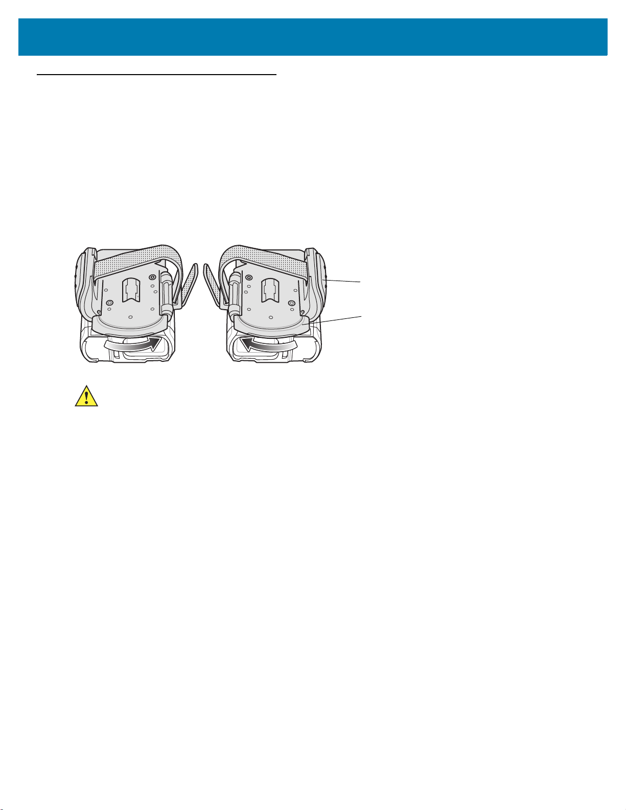
Trigger Swivel Assembly - Change Trigger Position
The RS6000 is worn on the index and middle fingers, and triggered with the thumb. The Trigger Swivel Assembly
of the RS6000 rotates to provide left-hand or right-hand use.
To change the position of the trigger:
1. Determine whether the RS6000 is used on the right or left hand and rotate the trigger swivel assembly.
Figure 3 Change Trigger Swivel Assembly Position
CAUTION: The Trigger Swivel Assembly only rotates 180° around the front of the scan assembly. Do not rotate
the Trigger Swivel Assembly past the designed stop.
Rotate the Trigger Swivel Assembly so that the Scan Trigger is positioned next to the thumb when the RS6000 is
placed on the index and middle fingers.
Charge the Battery
Before using the RS6000, charge the battery. To charge the RS6000 battery, refer to Accessories.
Install the Battery
1. Align the battery on top of the RS6000 and insert metal corner into the battery compartment.
2. Slide the battery all the way into the locking slot of the RS6000.
3. Firmly press the battery into the RS6000 until a click is heard ensuring the battery release latch is fully
engaged with the RS6000.
21
Page 22

Figure 4 Install the Battery
Locking Slot
Battery
Battery Release Latch
2
3
1
1
2
Remove the Battery
1. Hold the RS6000 in one hand.
2. Use finger tip to press the battery release latch.
Getting Started
Figure 5 Remove Battery
3. While holding down the battery release latch, pull up the battery to release it from the locking slots of the
RS6000.
Wearing the RS6000
1. Slide the RS6000 onto the index and middle fingers with the scan trigger next to the thumb.
2. Tighten the finger strap.
22
Page 23
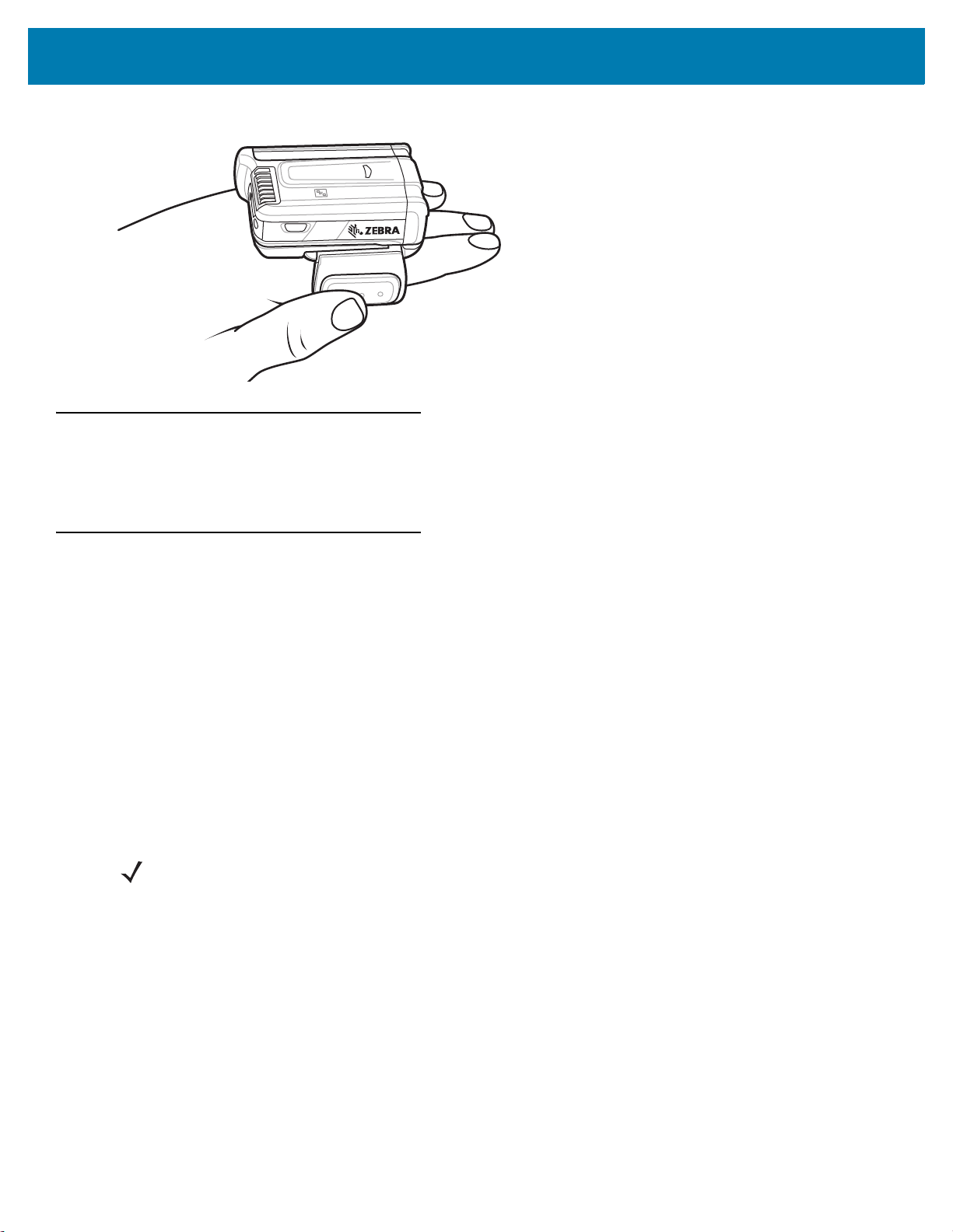
Figure 6 Wearing the RS6000
Bluetooth Connection
The RS6000 sends decoded bar code data to Zebra mobile computers and other devices using Bluetooth. Before
using, connect the RS6000 to a device using Bluetooth. See Bluetooth Communications for configuration.
Getting Started
Scanning
The RS6000 uses digital camera technology to take an image of a bar code and software decoding algorithms are
executed to extract the bar code data from the image.
Scan Triggering Modes
Manual Triggering (Triggered models only)
1. Launch a scanning software application on the mobile computer.
2. Position the RS6000 approximately 22.8 cm (9 inches) from a bar code and press the Scan Trigger. Position
the cross hair laser beam to cover the bar code. The RS6000 takes a digital picture (image) of the bar code
and stores it in memory for decoding.
The Scan LED flashes green and a high beep sounds indicating that the bar code was properly decoded.
NOTE: In some configurations proper decoding of a bar code is indicated by the software application running on
the mobile computer.
Auto-triggering (Triggerless models only)
The RS6000 is provided with auto-triggering capability. In auto-triggering mode, both motion and proximity sensors
are used to trigger the RS6000 when the user intends to scan a bar code.
With auto-triggering activated, the RS6000 automatically scans when motion stops and a bar code is placed within
the detection field of the proximity sensor on the RS6000. The RS6000 scans the bar code and then switches to
low power mode to conserve power.
To scan a bar code in auto-triggering mode:
1. Launch a scanning software application on the mobile computer.
23
Page 24
Getting Started
Virtual rectangle made by the cross hair laser beam
Cross hair laser beam
2D Bar Code
1D Bar Code
Bar Codes
Aiming pattern Pattern
2. Position the RS6000 approximately 22.8 cm (9 inches) from a bar code. Aim the cross hair laser beam to cover
the bar code. The RS6000 takes a digital picture (image) of the bar code and stores it in memory for decoding.
The Scan LED flashes green and a high beep sounds indicating that the bar code was properly decoded.
NOTE: By default the proximity sensor is configured for medium range of up to 40.6 cm (16 inches). The range
can be adjusted for short or long range scanning, depending on the scanning application. See page 109.
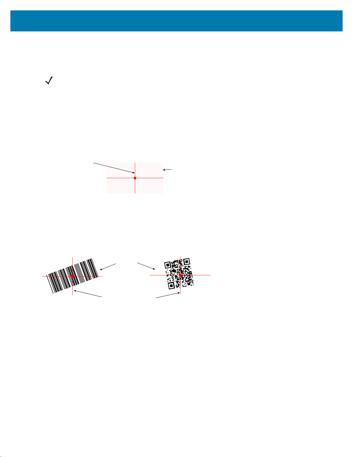
Aiming the RS6000
The aiming pattern of the RS6000 is a cross hair laser beam with bright center dot (see Figure 7). The virtual
rectangle made by the cross hair reflects the field of view of the RS6000. The aiming pattern is used to position the
bar code within the field of view.
Figure 7 Cross Hair Laser Beam
Enter the symbol in any orientation within the virtual rectangle made by the cross hair laser beam, making use of its
omnidirectional reading capability within the entire field of view.
Figure 8 Bar Code Scan Orientation
The RS6000 can also read a bar code presented within the aiming pattern but not centered (see the top bar codes
on Figure 9). The bar codes marked with X in Figure 9, however, show bar code aiming that may result in no
decode.
When using the application on your mobile computer in “Pick List” mode, the Bright Center Dot can be positioned
anywhere on the symbol (see Figure 7). The top examples in Figure 9 show acceptable aiming options, while the
bottom examples can not be decoded.
24
Page 25

Getting Started
012345
012345
012345
012345
Figure 9 Acceptable Aiming Options
The aiming pattern is smaller when the RS6000 is closer to the symbol and larger when it is farther from the bar
code. Scan bar codes with smaller bars or elements (mil size) closer to the RS6000 and those with larger bars or
elements (mil size) farther from the RS6000.
1. Position the RS6000 between two and eleven inches from the bar code (depending on the bar code density).
NOTE: When a bar code is under transparent plastic or on a mobile computer screen, it is recommended to use
a tilt (pitch) or skew scan angle to minimize reflection.
2. Aim the cross hair laser beam to cover the bar code. The RS6000 takes a digital picture (image) of the bar
code and stores it in memory for decoding.
The Scan LED flashes green and a high beep sounds indicating that the bar code was properly decoded.
Resetting the RS6000
If the RS6000 stops responding to input, reset it. There are three reset functions, warm boot, cold boot and clean
boot. Perform a warm boot first. If the RS6000 still does not respond, perform a cold boot. Perform clean boot to
restore the RS6000 to its factory default configuration.
Warm Boot
To perform warm boot, press and hold the Restore Key for more than three seconds and then release. The
RS6000 resets when the key is released.
Cold Boot
Cold boot restores the RS6000 operation by performing a power cycle of the device. To perform cold boot, remove
and re-insert the battery into the RS6000.
Clean Boot
Clean Boot restores the RS6000 to its factory default configuration.
To perform clean boot:
1. Remove battery.
25
Page 26

Getting Started
2. Press and hold the Restore Key.
3. Insert the battery into the RS6000.
4. Continue to press and hold the Restore Key for about five seconds until a chirp is heard and the Scan LEDs
flash green. The RS6000 is now in its factory default configuration.
NOTE: The factory default configuration is set in the factory or the service center. These parameters are unique
for each RS6000 and cannot be changed. The Factory default configuration includes: RS6000 serial number,
Bluetooth Device (BD) address, model number, production date and proximity calibration.
Configuration parameters modified on the RS6000 reset to factory defaults after a clean boot.
26
Page 27

Bluetooth Communications
*Enable Fuzzy 1D Processing
Feature/Option
* Indicates Default
Introduction
This chapter provides information about the modes of operation and features available for wireless communication
between the RS6000 and hosts. The chapter also includes the parameters necessary to configure the RS6000.
The RS6000 ships with the settings shown in the Bluetooth Communication Defaults on page 28 (also see
Standard Default Parameters for all host device and miscellaneous RS6000 defaults). If the default values suit user
requirements, programming is not necessary.
To set feature values, scan a single bar code or a short bar code sequence. The settings are stored in non-volatile
memory and are preserved even when the RS6000 is powered down.
To return all features to default values, scan a default bar code in Default Parameters on page 115. Throughout the
programming bar code menus, default values are indicated with asterisks (
*).
Scanning Sequence Examples
In most cases, scan one bar code to set a specific parameter value.
Errors While Scanning
Unless otherwise specified, to correct an error during a scanning sequence, just re-scan the correct parameter.
27
Page 28

Bluetooth Communications
Bluetooth Communications Parameter Defaults
Table 3 lists the defaults for Bluetooth radio communication parameters. If you wish to change any option, scan the
appropriate bar code(s).
NOTE: See Standard Default Parameters for all user preferences, hosts, symbologies, and miscellaneous
default parameters.
In this guide, the parameter numbers listed are the same as the attribute numbers for these parameters.
See Country Codes for Country Keyboard Types (Country Codes).
Table 3 Bluetooth Communication Defaults
Parameter
Bluetooth Communications Host Types SSI Bluetooth Classic
Discoverable Mode 610 General 57
Wi-Fi Friendly Mode Disable 61
Wi-Fi Friendly Channel Exclusion Use All Channels 62
Radio Output Power 1324 Class 2 64
Link Supervision Timeout 1698 .5 Seconds 65
HID Wait for Connection 1714 Disable 34
HID Features for Apple iOS 1114 Disable 35
HID Keyboard Keystroke Delay No Delay (0 msec) 35
CAPS Lock Override Disable 36
Ignore Unknown Characters Enable 36
Emulate Keypad Disable 37
Fast HID Keyboard 1361 Enable 37
Parameter
Number
Default
Page
Number
Quick Keypad Emulation 1362 Enable 38
Keyboard FN1 Substitution Disable 38
Function Key Mapping Disable 39
Simulated Caps Lock Disable 39
Convert Case No Case Conversion 40
Beep on Reconnect Attempt 559 Disable 67
Reconnect Attempt Interval 558 30 sec 68
Auto-reconnect 604 Auto-reconnect
Immediately
Bluetooth Disconnect Indication 822 Disable 71
70
28
Page 29

Bluetooth Communications
Table 3 Bluetooth Communication Defaults (Continued)
Parameter
Bluetooth Disconnect Indication After Battery
Insert
Bluetooth Disconnect Indication After Bluetooth
Disconnection
Bluetooth Disconnect Indication - Cycle Time 10 sec 74
Bluetooth Disconnect Indication - Beep Type 3 High/Short Beeps 75
Beep on Insertion 288 Enable 117
Beep on <BEL> 150 Enable 51
Toggle Pairing 1322 Disable 76
Force Pairing Save 795 Enable 76
Auto Unpairing 1708 Disable 77
Batch Mode 544 Normal (Do Not Batch
PIN Code (Set and Store) 552 12345 58
Variable Pin Code 608 Static
Parameter
Number
823 120 sec 72
824 30 sec 73
Data)
(Default PIN code is
12345)
Default
79
59
Page
Number
Bluetooth Security Levels 1393 Low 60
Bluetooth Status Indications
When the RS6000 is pairing or re-establishing a connection to a computer, it issues various beep sequences
indicating successful or unsuccessful operations. See Table 2 on page 19 for all beep sequences and LED
displays including those which occur during pairing operations.
Bluetooth Connection Modes
The RS6000 can connect to a host computer using the following Bluetooth modes:
• Human Interface Device (HID)
• Simple Serial Interface (SSI)
• Serial Port Profile (SPP).
Keyboard Emulation
The Bluetooth Human Interface Device (HID) profile enables the RS6000 to emulate a Bluetooth keyboard input
device and connect to a host computer. The RS6000 supports two versions of the Bluetooth HID profile.
29
Page 30

Bluetooth Communications
HID Bluetooth Classic
Enables the RS6000 to communicate using Bluetooth HID profile to a host computer through Bluetooth Classic
radio. The RS6000 is capable of operating in Slave (discoverable) or Master mode.
HID Bluetooth Low Energy (Discoverable)
Enables the RS6000 to communicate using Bluetooth HID profile to a host computer through Bluetooth Low
Energy radio. The RS6000 operates in Slave (discoverable) mode when BT HID Low Energy is enabled.
Low Energy (LE) Bluetooth has a smaller RF footprint (bandwidth) than Classic Bluetooth. The smaller RF footprint
of LE Bluetooth significantly improves Wi-Fi co-existence. Due to its smaller RF bandwidth, LE Bluetooth is up to
seven times slower than Classic Bluetooth (0.27 Mbps versus 0.7-2.1 Mbps). Data intensive activities such as
firmware updates, can take significantly longer.
NOTE: Not all host devices support Bluetooth Low Energy. Verify that your device supports Bluetooth Low
Energy mode before attempting to connect to the RS6000.
Table 4 HID Bluetooth Bar Codes
HID Bluetooth Classic
HID Bluetooth Low Energy
HID Setup
HID Bluetooth Connection to iOS/iPad/iPhone
1. Perform clean boot. See Clean Boot on page 25
2. Scan the appropriate HID Bluetooth Bar Code from page 30.
3. Perform a Cold Boot by removing and re-installing the battery onto the RS6000. The RS6000 starts to operate
and is discoverable as a keyboard.
4. Select Settings > General > Bluetooth.
5. Turn Bluetooth ON.
6. Select Bluetooth Settings
RS6000 - xxxxxx, where xxxxxx is the serial number.
and choose RS6000 from the list of discovered devices. The RS6000 displays as
HID Bluetooth Connection to Android
1. Perform clean boot. See Clean Boot on page 25
30
Page 31

Bluetooth Communications
2. Scan the appropriate HID Bluetooth Bar Code from page 30.
3. Perform a Cold Boot by removing and re-installing the battery onto the RS6000. The RS6000 starts to operate
and is discoverable as a keyboard.
4. Select Settings > Wireless & Networks > Bluetooth
5. Turn Bluetooth ON.
6. Select Bluetooth Settings
and choose RS6000 from the list of discovered devices. The RS6000 displays as
RS6000 - xxxxxx, where xxxxxx is the serial number.
IMPORTANT: Some devices may require scanning a PIN to connect. If so, a PIN displays on the device. To
enter the required PIN, scan the bar code, Variable PIN Code on page 59 then re-attempt connection. When a
beep sounds, indicating the RS6000 is waiting for PIN entry, scan the PIN using the Alphanumeric and Numeric
Bar Codes on page 323. Incorrect scanned entries can be deleted by scanning Cancel on page 324.
For more information, see Variable PIN Code on page 59.
HID Bluetooth Connection to Windows 7 or 8
NOTE: For best user experience, it is recommend using Secure Simple Pairing (SSP). Windows 7 SP1 supports
Bluetooth 2.1 and as such, supports SSP.
SSP reduces the number of steps to minimal or none when compared to legacy Bluetooth pairing.
If the host computer does not include an integrated Bluetooth module, use a USB Bluetooth dongle.
Use off-the-shelf dongle that supports Bluetooth v2.1 for effortless pairing in SSP.
To pair and connect the RS6000:
1. Perform clean boot. See Clean Boot on page 25
2. Scan the HID Bluetooth Classic bar code from page 30.
3. Perform a Cold Boot by removing and re-installing the battery onto the RS6000. The RS6000 starts to operate
and is discoverable as a keyboard.
4. Right click on Bluetooth icon and select Add a Device (Windows 7) or Add a Bluetooth Device (Windows 8).
Figure 10 HID - Adding a Device - Windows
5. From the Add a device screen, select the RS6000 (shown as Bluetooth Keyboard) and click Next.
31
Page 32

Bluetooth Communications
Windows 7
Windows 8
Windows 7
Windows 8
Figure 11 HID - Add Device Screen - Windows
The computer connects to the RS6000 and the following screen displays.
Figure 12 HID - Device Successfully Added Screen - Windows
Demonstrating HID Connection
Following a successful connection, data can be scanned into any Windows, iOS or Android application field that
accepts keyboard data; for example, in Windows, the Notepad application.
To scan a bar code:
1. Open the Notepad application.
2. Click in the text area.
3. Scan a bar code. The scanned bar code information displays on the Notepad window.
32
Page 33

Bluetooth Communications
Figure 13 HID - Scanned Bar Code Information On Notepad Window
33
Page 34

Bluetooth Communications
HID Options
The RS6000 supports virtual keyboard emulation for the Apple iOS, and keyboard emulation over the Bluetooth
HID profile. In this mode the RS6000 can interact with Bluetooth enabled hosts supporting the HID profile as a
Bluetooth keyboard. Scanned data is transmitted to the host as keystrokes.
HID - Wait for Connection
Parameter # 1714
NOTE: This setting applies to first time connection only, when scanner connects to remote device by scanning a
paring bar code.
When disabled, the scanner issues a connection after scanning a pairing bar code. This is the recommended
setting for Android devices.
When enabled, the scanner waits for a connection request from a remote device, after scanning a pairing bar code
and initiating pairing. This is the recommended setting for Windows devices and VC80.
* Disable
(0)
Enable
(1)
34
Page 35

Bluetooth Communications
HID Features for Apple iOS
Parameter # 1114
This option works with Apple iOS devices to enable the opening and closing of the iOS virtual keyboard by
double-pressing the trigger.
NOTE: When this feature is enabled, the RS6000 may be incompatible with non-Apple iOS devices.
*Disable
(0)
Enable
(1)
HID Keyboard Keystroke Delay
This parameter sets the delay, in milliseconds, between emulated keystrokes. Scan a bar code below to increase
the delay when the HID host requires a slower transmission of data.
*No Delay (0 msec)
Medium Delay (20 msec)
Long Delay (40 msec)
35
Page 36

Bluetooth Communications
HID CAPS Lock Override
When enabled, the case of the data is preserved regardless of the state of the caps lock key. This setting is always
enabled for the “Japanese, Windows (ASCII)” keyboard type and can not be disabled.
*Do Not Override Caps Lock Key
(Disable)
Override Caps Lock Key
(Enable)
HID Ignore Unknown Characters
This option applies only to the HID Keyboard Emulation device and IBM device. Unknown characters are
characters the host does not recognize. When Send Bar Codes With Unknown Characters is selected, all bar
code data is sent except for unknown characters, and no error beeps sound. When Do Not Send Bar Codes With
Unknown Characters is selected, bar code data is sent up to the first unknown character, then the RS6000 issues
an error beep.
*Send Bar Codes With Unknown Characters
(Enable)
Do Not Send Bar Codes With Unknown Characters
(Disable)
36
Page 37

Bluetooth Communications
Emulate Keypad
When enabled, all characters are sent as ASCII sequences over the numeric keypad. For example, ASCII A is sent
as "ALT make" 0 6 5 "ALT Break."
*Disable Keypad Emulation
Enable Keypad Emulation
Fast HID Keyboard
Parameter # 1361
This option transmits Bluetooth HID keyboard data at a faster rate.
Fast HID Disable
*Fast HID Enable
37
Page 38

Bluetooth Communications
Quick Keypad Emulation
Parameter # 1362
NOTE: This option applies only to a HID Keyboard Emulation Device which has Emulate Keypad enabled (see
Emulate Keypad on page 37).
This parameter enables a quicker method of keypad emulation where ASCII sequences are only sent for ASCII
characters not found on the keyboard.
Quick Keypad Emulation Disable
*Quick Keypad Emulation Enable
HID Keyboard FN1 Substitution
When enabled, this parameter allows replacement of any FN1 character in an EAN128 bar code with a Key
Category and value chosen by the user. See FN1 Substitution Values on page 138 to set the Key Category and
Key Value.
*Disable Keyboard FN1 Substitution
Enable Keyboard FN1 Substitution
38
Page 39

Bluetooth Communications
HID Function Key Mapping
ASCII values under 32 are normally sent as control-key sequences. When this parameter is enabled, the keys in
bold are sent in place of the standard key mapping (see ASCII Character Sets).
Table entries that do not have a bold entry remain the same whether or not this parameter is enabled.
*Disable Function Key Mapping
Enable Function Key Mapping
Simulated Caps Lock
When enabled, the RS6000 inverts upper and lower case characters on the RS6000 bar code as if the Caps Lock
state is enabled on the keyboard. This inversion is done regardless of the current state of the keyboard Caps Lock
state.
*Disable Simulated Caps Lock
Enable Simulated Caps Lock
39
Page 40

Bluetooth Communications
Convert Case
When enabled, the RS6000 converts all bar code data to the selected case.
*No Case Conversion
Convert All to Upper Case
Convert All to LowerCase
Country Keyboard Type Change
While in HID mode, the RS6000 supports several keyboard layouts.
To change the North American Standard Keyboards layout to a different country code layout, scan the required bar
code corresponding to the country keyboard type. See Country Codes for country keyboard types.
40
Page 41

Simple Serial Interface
SSI Bluetooth Classic
Enables communication with Zebra mobile computers. It enables the RS6000 to establish a connection with the
host computer over Classic Bluetooth radio.
Simple Serial Interface (SSI) is the RS6000 default connection mode. To set the RS6000 back to SSI mode:
1. Perform clean boot.
2. Scan the SSI Bluetooth Classic bar code.
3. Perform a cold boot by removing and re-installing the battery onto the RS6000.
NOTE: The RS6000 is not discoverable in this mode.
Bluetooth Communications
SSI Setup
SSI Bluetooth Connection using NFC
The RS6000 is NFC enabled and supports Bluetooth Tap-to-Pair.
To connect with a WT6000:
1. Check that NFC is enabled on the WT6000.
2. Align the NFC icon of the RS6000 with the NFC icon on the WT6000.
The Status LED blinks blue, indicating that the RS6000 is attempting to establish connection with the WT6000.
When connection is established, the Status LED turns off and the RS6000 emits a single string of low/high
beeps.
41
Page 42

Figure 14 Touch NFC Antennas
NFC Logo
Bluetooth Communications
NOTE: Not all Zebra device support NFC readers and the Tap-to-Pair feature.
SSI Bluetooth Connection using Scan2Pair
To pair the RS6000 with the WT6000 using SSI:
1. On the WT6000, touch > . The Bluetooth Pairing Utility opens.
Figure 15 Bluetooth Pairing Utility
2. Using the RS6000, scan the bar code on the screen.
The Status LED blinks blue indicating that the RS6000 is attempting to establish connection with the WT6000.
When connection is established, the Status LED turns off and the RS6000 emits a single string of low/high
beeps.
3. On the WT6000, touch the triangle button to return to the main screen.
42
Page 43

Bluetooth Communications
SSI Bluetooth Connection using STB3678 cradle
For information on STB3678 cradle configuration and usage refer to the DS36x8 user guide.
To pair the RS6000 with a STB3678 cradle:
1. Connect the STB3678 cradle to the host computer.
2. Using the RS6000, scan the pairing bar code on the STB3678 cradle.
The Status LED blinks blue indicating that the RS6000 is attempting to establish a connection with the
STB3678. When the connection is established, the Status LED turns off and the RS6000 emits a single string
of low/high beeps.
NOTE: Before pairing the RS6000 with a different device, perform clean boot. See Clean Boot on page 25.
43
Page 44

Serial Port Profile
The RS6000 can connect to a host computer or other device that supports Bluetooth Serial Port Profile (SPP). Use
Bluetooth SPP when connecting to a host computer, tablet, or phone in one of the following modes:
• Master - The RS6000 initiates the connection. When configured as SPP Master, that RS6000 is
non-discoverable and typically connects to a host using a pairing bar code. Scan the SPP Bluetooth
Classic (Non-Discoverable) bar code to set the RS6000 to this mode.
• Slave - The host computer or device discovers the RS6000 and initiates the connection. When the
RS6000 is configured as SPP Slave, it is in discoverable mode. Scan the Bluetooth Classic
(Discoverable) bar code to set the RS6000 to this mode.
Table 5 SPP Bluetooth Classic Bar Codes
SPP Bluetooth Classic (Non-Discoverable)
Bluetooth Communications
SPP Bluetooth Classic (Discoverable)
NOTE: Since the SPP connection does not support automatic acknowledgment when the data is received by the
computer application, a BELL indication is used.
The BELL indication allows the computer application to send single binary character 0x07 to the RS6000 (as
defined in ASCII table). Upon receiving the BELL character, the RS6000 beeps. To configure the beep, see Bell
Indication Control on page 52.
SPP Setup
SPP Bluetooth Connection to Windows 7 or 8 as Master
1. Perform clean boot. See Clean Boot on page 25.
2. Scan the SPP Bluetooth Classic (Non-Discoverable) bar code from Table 5.
3. Perform a Cold Boot by removing and re-installing the battery onto the RS6000. The RS6000 starts to operate
and is discoverable as a Bluetooth serial device.
4. Right click on the Bluetooth icon and select Open Setting to add a COM port
44
Page 45

Bluetooth Communications
Figure 16 .SPP - Open Setting Screen - Windows
5. Select the COM Ports tab and click Add.
Figure 17
.
SPP - Bluetooth Settings - Com Ports Tab
45
Page 46

Bluetooth Communications
6. Select the Incoming radio button and click OK.
Figure 18 SPP - Bluetooth Settings - Add Com Port Screen
7. Click the Hardware tab.
8. Click the Properties button.
9. Click the Advanced tab to retrieve the Bluetooth radio BD address in the Address field.
10. Click OK.
Figure 19 SPP - Bluetooth Settings - Bluetooth Radio BD Address
46
Page 47

Bluetooth Communications
11. Run the PC Tool application.
Figure 20 SPP - PC Tool application
12. Click the Show Bluetooth Address barcode button.
13. Manually enter the BD address to the PC Tool application and click the Generate button.
Figure 21 SPP - PC Tool Application - Bar Code Generator
14. Click Close.
47
Page 48

Bluetooth Communications
Windows 7
Windows 8
15. Open the incoming COM port assigned (for example, COM7) in the application. After the COM port is opened
the computer connects to the RS6000 and a beep will sound. For demonstration, refer to General Bluetooth
Options on page 57.
NOTE: If the COM port is not opened prior to the connection, the RS6000 will fail to connect.
16. To start the connection process aim the RS6000 at about 7" (18 cm) away from the computer screen and scan
the bar code of the BD address of the computer (or the other target device).
The RS6000 Scan LEDs start flashing green indicating that the RS6000 is attempting to establish connection
with the computer. The following notifications display upon successful connection.
Figure 22 SPP - Device Successfully Added Screen
NOTE: In case you do not hear the connected beep on the RS6000, press the RS6000 Restore key to connect.
SPP Bluetooth Connection to Windows 7 or 8 as Slave
1. Perform clean boot. See Clean Boot on page 25.
2. Scan the SPP Bluetooth Classic (discoverable) bar code from Table 5.
3. Perform a Cold Boot by removing and re-installing the battery onto the RS6000. The RS6000 starts to operate
and is discoverable as a Bluetooth serial device.
4. Right click the Bluetooth icon and select Add a Device (Windows 7) or Add a Bluetooth Device (Windows 8).
48
Page 49

Bluetooth Communications
Windows 7
Windows 8
Windows 7
Windows 8
Figure 23 SPP connection with RS6000 as a Slave - Open Settings
5. Select the RS6000 (see Bluetooth Camera icon below) and click Next
Figure 24 SPP connection with RS6000 as a Slave - Add Device Screen
6. The computer attempts to connect to the RS6000
Figure 25
.
SPP connection with RS6000 as a Slave - Device Successfully Added Screen
49
Page 50

Bluetooth Communications
7. Open the incoming COM port assigned (for example, COM7) in the application. After the COM port is opened
the computer connects to the RS6000 and a beep will sound. For demonstration, refer to General Bluetooth
Options on page 57.
NOTE: Make sure the same COM port is closed in other applications.
How to Demonstrate SPP Connection with a Computer
Once SPP connection is established, an application is required to demonstrate the RS6000.
To scan a bar code:
1. If the RS6000 is still connected to the PC Tool application, close the COM port on the PC Tool application.
2. Run a hyper terminal application such as the Tera Term application. (ayera.com/teraterm/download.cfm).
Figure 26 Tera Term Application Screen
3. Select the virtual COM port set for the RS6000 connection.
4. Scan bar codes. Successful decoding of a bar code is indicated by one green flash of the Scan LEDs and a
high beep sound. In case of Bluetooth disconnection, the RS6000 emits one high beep followed by four low
beeps.
50
Page 51

Bluetooth Communications
Figure 27 Tera Term Entry Screen
Beep on BELL Character
Parameter # 150
When this parameter is enabled, the RS6000 issues a beep when a <BEL> character is received over the SPP
connection to the host device.
NOTE: This parameter only applies to SPP (Serial Port Profile).
*Beep on <BEL> Enable
51
Beep on <BEL> Disable
Page 52

Bluetooth Communications
Bell Indication Control
The BELL Indication Control parameter configures the beep tone sequence of the bell indication when a BELL
character is received. This feature is valid only in SPP mode for PC connection.
GP_1_HI_SHORT
GP_2_HI_SHORT
GP_3_HI_SHORT
GP_5_HI_SHORT
GP_4_HI_SHORT
GP_1_LO_SHORT
52
Page 53

GP_2_LO_SHORT
Bluetooth Communications
GP_3_LO_SHORT
GP_4_LO_SHORT
GP_1_HI_LONG
GP_5_LO_SHORT
GP_2_HI_LONG
GP_3_HI_LONG
53
Page 54

GP_5_HI_LONG
Bluetooth Communications
GP_4_HI_LONG
GP_2_LO_LONG
GP_4_LO_LONG
GP_1_LO_LONG
GP_3_LO_LONG
54
GP_5_LO_LONG
Page 55

Bluetooth Communications
GP_FAST_WARBLE
GP_SLOW_WARBLE
GP_HI_LO
GP_HI_LO_HI
GP_LO_HI
GP_LO_HI_LO
GP_HI_HI_LO_LO
55
Page 56

APP_CLICK
Bluetooth Communications
APP_ERROR_BEEP
LOW_CLICK
56
Page 57

General Bluetooth Options
Discoverable Mode
Parameter # 610
Select a discoverable mode based on the device initiating discovery:
• Select General Discoverable Mode when initiating connection from a PC.
• Select Limited Discoverable Mode when initiating connection from a PC or mobile device, and the
RS6000 does not appear in General Discoverable Mode. Note that it can take longer to discover the
device in this mode.
The RS6000 remains in Limited Discoverable Mode for 30 seconds, and the blue LED flashes while in this
mode. It is then non-discoverable. To re-active Limited Discoverable Mode, press the trigger.
Bluetooth Communications
*General Discoverable Mode
(0)
Limited Discoverable Mode
(1)
57
Page 58

Bluetooth Communications
Bluetooth Security
The RS6000 supports Bluetooth authentication. Authentication can be requested by either the remote device or the
RS6000.
NOTE: A remote device can still request authentication.
PIN Code
Parameter # 552
NOTE: The default PIN code is 12345.
To set and store a PIN code (e.g., password) on the RS6000 to connect to the host:
1. Scan the Set & Store PIN Code bar code below.
2. Scan five alphanumeric programming bar codes using the alphanumeric bar codes beginning on page 323.
3. Scan End of Message on page 331.
If the RS6000 communicates with a remote device with security enabled, synchronize the PIN codes on the
RS6000 and remote device. To achieve this, connect the RS6000 to the host when setting the PIN codes. If the
RS6000 is not connected to a host, the PIN code change only takes affect on the RS6000. If is required between
the RS6000 and host, and the PIN codes do not match, pairing fails.
NOTE: An extended 16 character PIN code is available for additional security with Open Bluetooth
(SPP and HID).
Set and Store PIN Code
58
Page 59

Bluetooth Communications
Variable PIN Code
Parameter # 608
When connecting to a host device with authentication enabled, scan Static PIN Code below to avoid entering the
PIN code manually. The PIN stored in memory is used. Scan the Variable PIN Code below to manually enter a
PIN code with each connection.
The default PIN code is the user-programmed PIN set and stored above. Typically, however, HID connections
require entering a Variable PIN Code. If, when attempting connection, the application presents a text box that
includes a PIN, scan the Variable PIN Code bar code, then re-attempt connection. When you hear a beep
indicating the RS6000 is waiting for an alphanumeric entry, enter the provided variable PIN using the Alphanumeric
and Numeric Bar Codes on page 323, then scan End of Message on page 331 if the code is less than 16
characters. The RS6000 discards the variable PIN code after connection.
*Static PIN Code
(0)
Variable PIN Code
(1)
59
Page 60

Bluetooth Communications
Bluetooth Security Levels
Parameter # 1393
• Low Bluetooth Security - The low security setting is designed for ease of connection with most devices.
This setting may be unacceptable to some devices. If connection fails, try re-connecting after increasing
security setting on the RS6000.
If connecting to Bluetooth 2.1 device and above, Just Works method for secure and simple pairing is used
NOTE: Data is encrypted using the Low Bluetooth security setting if connected to a Bluetooth 2.1 and above
device.
• Medium Bluetooth Security - The medium security setting may require a passkey for the initial
connection to pair RS6000 and device.
If connecting to Bluetooth 2.1 device and above,
used.
• High Bluetooth Security - The high security setting enables
2.1 and above. Not all devices are able to support this mode.
Passkey Entry
Man in the Middle
method for secure and simple pairing is
protection for Bluetooth
• Legacy Bluetooth Security (Bluetooth 2.0 and below) - The legacy security setting enables
authentication and encryption for legacy pairing.
*Low Bluetooth Security
.
High Bluetooth Security
Medium Bluetooth Security
Legacy Bluetooth Security
60
Page 61

Bluetooth Communications
Wi-Fi Friendly Mode
Scanners configured for Wi-Fi friendly mode behave as follows:
• The RS6000 remains in sniff mode, and exits sniff mode only during firmware update.
• If any Wi-Fi channel is excluded from the hopping sequence, AFH turns off.
• RS6000 avoid the selected Wi-Fi channels after establishing connection.
Notes
• If using this feature, configure all RS6000 in the area for Wi-Fi friendly mode.
• By default, no Wi-Fi channels are excluded.
• Since Bluetooth requires a minimum of 20 channels when Wi-Fi channels 1, 6, and 11 are excluded,
a smaller number of channels are cut from the hopping sequence.
• Updating Wi-Fi friendly settings before Bluetooth connection is recommended.
Scan a bar code below to enable or disable Wi-Fi Friendly Mode, then see Wi-Fi Friendly Channel Exclusion to
select any channels to exclude.
*Disable Wi-Fi Friendly Mode
Enable Wi-Fi Friendly Mode
61
Page 62

Bluetooth Communications
Wi-Fi Friendly Channel Exclusion
Select the channels to exclude:
• Exclude Wi-Fi channel 1: Bluetooth channels 0-21 are excluded from hopping sequence
(2402-2423 MHz).
• Exclude Wi-Fi channel 6: Bluetooth channels 25-46 are excluded from hopping sequence
(2427 - 2448 MHz).
• Exclude Wi-Fi channel 11: Bluetooth channels 50-71 are excluded from hopping sequence
(2452 - 2473 MHz).
• Exclude Wi-Fi channel 1, 6 and 11: Bluetooth channels 2-19 (2404-2421 MHz),
26-45 (2428 - 2447 MHz) and 51-69 (2453 - 2471 MHz) are excluded from hopping sequence.
• Exclude Wi-Fi channels 1 and 6: Bluetooth channels 0-21 (2402-2423 MHz) and 25-46
(2427 - 2448 MHz) are excluded from hopping sequence.
• Exclude Wi-Fi channels 1 and 11: Bluetooth channels 0-21 (2402-2423 MHz) and 50-71
(2452 - 2473 MHz) are excluded from hopping sequence.
• Exclude Wi-Fi channel 6 and 11: Bluetooth channels 25-46 (2427 - 2448 MHz) and 50-71
(2452 - 2473 MHz) are excluded from hopping sequence.
*Use All Channels (Standard AFH)
Exclude Wi-Fi Channel 6
Exclude Wi-Fi Channel 1
Exclude Wi-Fi Channel 11
62
Page 63

Bluetooth Communications
Exclude Wi-Fi Channels 1, 6, and 11
Exclude Wi-Fi Channels 1 and 11
Exclude Wi-Fi Channels 1 and 6
Exclude Wi-Fi Channels 6 and 11
63
Page 64

Bluetooth Communications
Radio Output Power
Parameter # 1324
RS6000 uses a configurable radio which can be configured to operate in:
• Low power mode as a Class 2 device
• High power mode as Class 1 device.
Increase the radio output power to increase range. Scan a bar code to select the desired power mode.
Class 1 (High Power)
*Class 2 (Low Power)
64
Page 65

Bluetooth Communications
Link Supervision Timeout
Parameter # 1698
Link supervision timeout controls how quickly the RS6000 senses that the Bluetooth radio lost connection to the
remote device. A lower value helps prevent data loss at the edge of the operating range while a larger value helps
prevent disconnects due to the remote device not responding in time. If you are experiencing occasional
disconnects and the RS6000 is able to reconnect, increase the link supervision timeout value.
NOTE: The RS6000 only controls Link Supervision Timeout in Master mode.
*0.5 Seconds
5 Seconds
20 Seconds
2 Seconds
10 Seconds
65
Page 66

Bluetooth Communications
Reconnecting
When in SPP Master, SSI Bluetooth Classic, and Bluetooth HID, the RS6000 automatically tries to reconnect to a
remote device when a disconnection occurs that is due to the radio losing communication. This can happen if the
RS6000 goes out of range with the remote device, or if the remote device powers down. The RS6000 initiates
auto-reconnect based the Auto-Reconnect setting. The duration of the auto-reconnect attempt is specified by the
Reconnect Attempt Interval setting. During reconnection, the Status LED blinks blue.
If the auto-reconnect process fails due to:
• Page Time-Outs - The RS6000 sounds a page timeout beep (long low/long high) and enters low power
mode.
• Connection Attempt Rejected - The RS6000 sounds a connection reject beep sequence (see Status LED
Indications on page 19) and enters low power mode.
NOTE: If a bar code is scanned while the auto-reconnect sequence is in process, a transmission error beep
sequence sounds and the data is not transmitted to the host. After a connection is reestablished, normal
scanning operation returns.
Switching between Bluetooth host types by scanning a host type bar code causes the radio to be reset. Scanning
is disabled during this time. It takes several seconds for the RS6000 to re-initialize the radio at which time
scanning is enabled.
Restore Lost Bluetooth Connection
If the auto-reconnect process fails and times out, the Bluetooth connection is re-established as follows:
1. Ensure that the RS6000 is within a range of 10 meters (30 feet) from the mobile computer.
2. Ensure that the mobile computer is on and “awake” (not in Suspend mode).
3. Briefly press the Restore Key on the RS6000 to initiate the reconnect process.
4. The Status LED starts flashing blue indicating that the RS6000 is attempting to establish connection with a
mobile computer. The Status LED turns off and the RS6000 emits one string of low/high beeps indicating that
the RS6000 is connected and ready for scanning.
66
Page 67

Bluetooth Communications
Reconnect Attempt Beep Feedback
Parameter # 559
When the RS6000 disconnects as it goes out of range, it immediately attempts to reconnect. While the RS6000
attempts to reconnect, the Status LED continues to blink blue. If the auto-reconnect process fails, the RS6000
emits a page timeout beep (long low/long high) and the Status LED stops blinking. The process can be restarted by
pulling the trigger or pressing the restore key.
The Beep on Reconnect Attempt feature is disabled by default. When enabled, the RS6000 emits five short high
beeps every five seconds while the re-connection attempt is in progress. Scan a bar code below to enable or
disable Beep on Reconnect Attempt.
*Disable Beep on Reconnect Attempt
(0)
Enable Beep on Reconnect Attempt
(1)
67
Page 68

Bluetooth Communications
Reconnect Attempt Interval
Parameter # 558
When a RS6000 disconnects as it goes out of range, it immediately attempts to reconnect for the default time
interval of 30 seconds. This time interval can be changed to one of the options below.
To set the Reconnect Attempt Interval, scan one of the bar codes below.
*Attempt to Reconnect for 30 Seconds
(6)
Attempt to Reconnect for 5 Minutes
(60)
Attempt to Reconnect for 1 Minute
(12)
Attempt to Reconnect for 30 Minutes
(360)
68
Page 69

Bluetooth Communications
Attempt to Reconnect for 1 Hour
(720)
Attempt to Reconnect Indefinitely
(0)
69
Page 70

Bluetooth Communications
Auto-reconnect
Parameter # 604
In Bluetooth Keyboard Emulation (HID) mode, SPP Master, and SSI Bluetooth Classic, select a re-connect option
for when the RS6000 loses its connection with a remote device:
• Auto-reconnect on Bar Code Data: The RS6000 auto-reconnects when you scan a bar code. With this
option, a delay can occur when transmitting the first characters. The RS6000 sounds a decode beep upon
bar code scan, followed by a connection, a page timeout, a rejection beep, or a transmission error beep.
Select this option to optimize battery life on the RS6000 and mobile device. Note that auto-reconnect does
not occur on rejection commands.
• Auto-reconnect Immediately: When the RS6000 loses connection, it attempts to reconnect. If a page
timeout occurs, the RS6000 attempts reconnect by pulling the trigger or pressing the restore key. Select
this option if the RS6000 battery life is not an issue and you do not want a delay to occur when the first bar
code is transmitted. Note that auto-reconnect does not occur on rejection commands.
• Disable Auto-reconnect: When the RS6000 loses connection, you must re-establish it manually.
Auto-reconnect on Bar Code Data
(1)
Disable Auto-reconnect
(0)
*Auto-reconnect Immediately
(2)
70
Page 71

Bluetooth Communications
Bluetooth Disconnection Alert Control
Bluetooth Disconnect Indication
When this parameter is enabled, the RS6000 plays a beep every 10 seconds when the RS6000 Bluetooth is
disconnected.
*Disable
Enable
71
Page 72

Bluetooth Communications
Bluetooth Disconnect Indication After Battery Insert
Time delay for Bluetooth disconnect indication after battery installed.
60 Seconds
*120 Seconds
180 Seconds
300 Seconds
240 Seconds
72
Page 73

Bluetooth Communications
Bluetooth Disconnect Indication After Bluetooth Disconnection
Time delay for Bluetooth disconnect indication after Bluetooth disconnection.
*30 Seconds
60 Seconds
90 Seconds
120 Seconds
73
Page 74

Bluetooth Communications
Bluetooth Disconnect Indication - Cycle Time
Sets the period of Bluetooth disconnect indication.
*10 Seconds
30 Seconds
60 Seconds
90 Seconds
74
Page 75

Bluetooth Communications
Bluetooth Disconnect Indication - Beep Type
*3 High/Short Beeps
3 Low/Short Beeps
3 High/Long beeps
High/Low/High Beep
75
Page 76

Bluetooth Communications
Pairing Support
Toggle Pairing
Parameter # 1322
If the RS6000 is configured for Toggle Pairing, scanning a pairing bar code a second time will unpair the scanner.
*Toggle Pairing Disable
Toggle Pairing Enable
Force Pairing Save
The Force Pairing Save parameter enables/disables saving the remote Bluetooth address after each Bluetooth
connection attempt.
When this parameter is disabled, the Bluetooth address is saved only after a successful Bluetooth connection. If
the Bluetooth connection fails, the Bluetooth address is not saved.
NOTE: This parameter is effective when the RS6000 connects as Master.
Disable
76
*Enable
Page 77

Bluetooth Communications
Auto Un-Pairing
Parameter # 1708
The auto un-pair parameter configures the RS6000 to un-pair from the host computer on specific events.
• Disable (default) - the RS6000 will not auto un-pair on any events.
• On cradle insertion - the RS6000 will un-pair when inserted charging cradle
• On reset - the RS6000 will un-pair if a warm or cold reset occurs
• On cradle or reset - the RS6000 will un-pair on cradle insertion or reset event.
*Disable
On Reset
Un-pair on Cradle Insertion
On Cradle or Reset
77
Page 78

Bluetooth Communications
Paring Bar Code Content:
‘B’ + Bluetooth Address
B112233445566
Pairing Bar Code Format
When pairing the RS6000 to certain host devices in SSI Bluetooth Classic, SPP Bluetooth Master or Bluetooth
HID, it is necessary to create a pairing bar code. The RS6000 scans the pairing bar code and initiates the
connection to the host computer. To create a pairing bar code label, the Bluetooth address of the remote device
must be known (refer to the mobile computer user guide).
Pairing bar codes are Code 128 or Data Matrix symbologies formatted as follows:
<Fnc 3>Bxxxxxxxxxxxx
where:
• B (or LNKB) is the prefix
• xxxxxxxxxxxx represents the 12-character Bluetooth address.
Pairing Bar Code Example
If the mobile computer Bluetooth address is 11:22:33:44:55:66, then the pairing bar code is:
Figure 28 Creating a Pairing Bluetooth Bar Code
Unpairing
Unpair the RS6000 from the host computer to make the host computer available for pairing with another RS6000.
Scan the bar code below to disconnect the RS6000 from its host computer.
Unpairing
78
Page 79

Bluetooth Communications
Batch Mode
Parameter # 544
IMPORTANT: Batch mode only applies for HID and SPP Master Mode.
The RS6000 supports five versions of batch mode. When the RS6000 is configured for any of the batch modes, it
attempts to store bar code data (not parameter bar codes) until transmission is initialized, or the maximum number
of bar codes are stored. When a bar code is saved successfully, a good decode beep sounds and the LED flashes
green. If the RS6000 is unable to store a new bar code, a low/high/low/high out of memory beep sounds. (See
page 19 for all beeper and LED definitions.)
In all modes, calculate the amount of data (number of bar codes) the RS6000 can store as follows:
Number of storable bar codes = 9,000 bytes of memory / (number of characters in the bar code + 3).
NOTE: If the batch mode selection is changed while there is batched data, the new batch mode takes
effect only after all the previously batched data is sent
Modes of Operation
.
• Normal (default) - Do not batch data. The RS6000 attempts to transmit every scanned bar code.
• Out of Range Batch Mode - The RS6000 starts storing bar code data when it loses its connection to a
remote device (for example, when a user holding the RS6000 walks out of range). Data transmission is
triggered by re-establishing the connection with the remote device (for example, when a user holding the
RS6000 walks back into range).
• Standard Batch Mode - The RS6000 starts storing bar code data after Enter Batch Mode is scanned.
Data transmission is triggered by scanning Send Batch Data.
NOTE: Transmission is halted if the connection to the remote device is lost.
In all modes, transmissions are halted if the RS6000 is moved out of range. The RS6000 resumes when it is back
in range. If a bar code is scanned while batch data is transmitted it is appended to the end of the batched data;
parameter bar codes are not stored.
*Normal
(00h)
79
Out of Range Batch Mode
(01h)
Page 80

Standard Batch Mode
(02h)
Bluetooth Communications
Enter Batch Mode
Send Batch Data
80
Page 81

Accessories
Accessories
Table 6 Accessories
Accessory Part Number Description
Cradles
1-Slot RS6000 USB
Charging Cradle
2-Slot WT6000/RS6000
USB Charging Cradle
5-Slot RS6000 Charge Only
Cradle
10-Slot WT6000/RS6000
Charge Only Cradle
10-Slot RS6000 Charge
Only Cradle
CRD-NGRS-1S1BU-01 Provides RS6000 and spare battery charging and
USB communication with a host computer. Use with
power supply, p/n PWRS-14000-148R and country
specific grounded AC line cord.
CRD-NWTRS-2SUCH-01 Provides WT6000 and RS6000 charging and USB
communication with a host computer. Use with
power supply, p/n PWRS-14000-148R and country
specific grounded AC line cord.
CRD-NGRS-5S5BC-01 Charges up to five RS6000 devices and five spare
batteries. Use with power supply, p/n
PWRS-14000-241R, DC line cord, p/n
50-16002-029R and country specific grounded AC
line cord.
CRD-NWTRS-10SCH-01 Charges up to five WT6000 devices and up to five
RS6000 scanners. Use with power supply, p/n
PWRS-14000-241R, DC line cord, p/n
50-16002-029R and country specific grounded AC
line cord.
CRD-NGRS-10SCH-01 Charges up to 10 RS6000 devices. Use with power
supply, p/n PWRS-14000-241R, DC line cord, p/n
50-16002-029R and country specific grounded AC
line cord.
Batteries and Chargers
Replacement Battery BTRY-NWTRS-33MA-01 Replacement battery for WT6000 and RS6000
(single pack).
4-Slot Battery Charger SAC-NWTRS-4SCH-01 Charges up to four spare batteries. Requires power
supply, p/n PWRS-14000-148R and country specific
grounded AC line cord.
81
Page 82

Accessories
Table 6 Accessories (Continued)
Accessory Part Number Description
20-Slot Battery Charger SAC-NWTRS-20SCH-01 Charges up to 20 spare batteries. Use with power
supply, p/n PWRS-14000-241R, DC line cord, p/n
50-16002-029R and country specific grounded AC
line cord.
Mounting Brackets
Rack Mount Bracket BRKT-SCRD-SMRK-01 Use for mounting a 5-Slot cradle or four 4-Slot
Battery Chargers on a rack.
Cables
2-Way DC Cable 25-122026-02R
4-Way DC Cable 25-85992-01R
DC Y Cable 25-85993-01R Provides power from the PWRS-14000-241R power
supply to two 4-Slot Battery Chargers.
DC Line Cord 50-16002-029R Provides power from the power supply to the 5-Slot
Charge Only Cradle, and the 5-Slot Charge Only
Cradle with Battery Charge.
Micro-USB to USB Cable 25-124330-01R Provides USB communication from a 1-Slot RS6000
USB Charging Cradle or 2-Slot WT6000/RS6000
USB Charging Cradle to a host computer.
Power Supplies
Power Supply PWRS-14000-148R Provides power to the 2–Slot cradles and 4-Slot
Spare Battery Charger. Requires country specific
grounded AC line cord.
Power Supply PWRS-14000-241R Provides power to the 5-Slot Charge Only Cradle,
and the 5-Slot Charge Only Cradle with Battery
Charger. Requires DC Line Cord, p/n 50-16002–
029R and country specific grounded AC line cord.
Soft Goods
RS6000 Spare Finger
Straps
RS6000 Spare Finger
Straps
RS6000 Spare Strap
Buckles
RS6000 Spare Trigger
Assembly
SG-NGRS-STRPK-10 Replacement finger strap for triggered configuration
(10-pack).
SG-NGRS-STRPK2-10 Replacement finger strap for triggerless
configuration (10-pack).
SG-NGRS-STBKL-10 Replacement strap buckles (10-pack).
SG-NGRS-TRGA-01 Replacement trigger assembly.
RS6000 Spare Comfort Pad SG-NGRS-CMPD-01 Replacement comfort pad.
RS6000 Spare Triggerless
Strap Holder
SG-NGRS-TRLH-01 Replacement strap holder.
82
Page 83

Accessories
Spare Battery
Charging LED
Spare Battery Slot
Power LED
RS6000 Charging Slot
RS6000 Charging
LED
1-Slot RS6000 USB Charging Cradle
NOTE: Ensure that you follow the guidelines for battery safety described in Battery Safety Guidelines on page 280.
The 1-Slot RS6000 USB Charging Cradle:
• provides 5 VDC (nominal) power for operating the RS6000
• provides USB communication with a host computer
• charges a spare battery.
Figure 29 1-Slot RS6000 USB Charging Cradle
83
Page 84

Accessories
AC Line Cord
Power Supply
USB Cable
Power Input
Micro-USB Port
Spare Battery Charging LED
Spare Battery Charing Slot
RS6000 Charging Slot
RS6000 Charging LED
Figure 30 1-Slot RS6000 Charging Cradle Setup
Charging the RS6000
1. Insert the RS6000 into the RS6000 charging slot.
Figure 31 Insert RS6000 into Cradle
2. Ensure the RS6000 is seated properly. The RS6000 Charging LED blinks indicating charging.
Charging the Spare Battery
1. Insert a spare battery into the spare battery slot.
84
Page 85

Accessories
Figure 32 Insert Battery into Cradle
2. Ensure the battery is seated properly. The Spare Battery Charging LED blinks indicating charging.
Battery Charging
The RS6000 Charging LED indicates the charging status of the battery in the RS6000 and the Spare Battery
Charging LED indicates the charging status of the spare battery. See Table 7 on page 85. The 3,350 mAh battery
fully charges in less than four hours at room temperature.
Table 7 Charging LED Indicators
State Indication
Off The battery is not charging. The battery is not inserted correctly in the cradle or
connected to a power source. Cradle is not powered.
Solid Amber Battery is charging.
Solid Green Battery charging is complete.
Fast Blinking Red
(2 blinks/second)
Solid Red Unhealthy battery is charging or fully charged.
Charge batteries in temperatures from 0 °C to 40 °C (32 °F to 104 °F). The device and cradle monitor the battery
temperature. Battery charging is only performed when the battery is within safe charging temperature limits. At
higher temperatures (e.g. approximately +35 °C (+95 °F)) the device or charging cradle may for small periods of
time alternately enable and disable battery charging to keep the battery at acceptable temperatures. This process
may require additional time to complete a full charge cycle. The cradle indicates when charging is disabled due to
abnormal temperatures via the Status LED.
Charging error, e.g.:
- Temperature is too low or too high.
- Charging has gone on too long without completion (typically eight hours).
85
Page 86

Accessories
RS6000 Charging LED
RS6000 Charging Slot
Power LED
WT6000 Charging Slot
WT6000 Charging LED
2-Slot WT6000/RS6000 USB Charging Cradle
NOTE: Ensure that you follow the guidelines for battery safety described in Battery Safety Guidelines on page 280.
The 2-Slot WT6000/RS6000 Charging Cradle:
• provides 5.4 VDC (nominal) power for operating the WT6000 and RS6000.
• provides USB communication with a host computer.
Figure 33 2-Slot WT6000/RS6000 Charging Cradle
86
Page 87

Accessories
AC Line Cord
Power Supply
USB Cable
Power Input
WT6000 Micro-USB Port
RS6000 Charging LED
RS6000 Charging Slot
WT6000 Charging Slot
WT6000 Charging LED
RS6000 Micro-USB Port
Figure 34 2-Slot WT6000/RS6000 Charging Cradle Setup
Charging the WT6000
1. Insert the WT6000 into the WT6000 charging slot.
Figure 35 Insert WT6000 into Cradle
2. Ensure the WT6000 is seated properly. The WT6000 Charging LED blinks indicating charging.
Charging the RS6000
1. Insert the RS600 into the RS6000 charging slot.
87
Page 88

Accessories
Figure 36 Insert RS6000 into Cradle
2. Ensure the RS6000 is seated properly. The RS6000 Charging LED blinks indicating charging.
Battery Charging
The WT6000 Charging LED indicates the charging status of the battery in the WT6000 and the RS6000 Charging
LED indicates the charging status of the battery in the RS6000. See Table 7 on page 85. The 3,350 mAh battery
fully charges in less than four hours at room temperature.
Charge batteries in temperatures from 0 °C to 40 °C (32 °F to 104 °F). The device and cradle monitor the battery
temperature. Battery charging is only performed when the battery is within safe charging temperature limits. At
higher temperatures (e.g. approximately +35 °C (+95 °F)) the device or charging cradle may for small periods of
time alternately enable and disable battery charging to keep the battery at acceptable temperatures. This process
may require additional time to complete a full charge cycle. The cradle indicates when charging is disabled due to
abnormal temperatures via the Status LED.
88
Page 89

Accessories
Spare Battery
Charging LED
Spare Battery Slot
Power LED
RS6000 Charging Slot
RS6000 Charging
LED
5-Slot RS6000 Charge Only Cradle
NOTE: Ensure that you follow the guidelines for battery safety described in Battery Safety Guidelines on page 280.
The 5-Slot Charge Only Cradle:
• Provides 5.4 VDC (nominal) power for operating the RS6000.
• Simultaneously charges up to five RS6000 devices.
• Simultaneously charges up to five spare batteries.
Figure 37 5-Slot RS6000 Charge Only Cradle
89
Page 90

Accessories
AC Line Cord
Power Supply
DC Line Cord
Power Input
Figure 38 5-Slot RS6000 Charge Only Cradle Setup
Charging the RS6000
To Charge the RS6000:
1. Insert the RS6000 into the RS6000 charging slot.
Figure 39 Insert RS6000 into Cradle
2. Ensure that the RS6000 is properly seated in the charging slot.
Charging the Spare Battery
1. Insert a spare battery into the spare battery slot.
90
Page 91

Accessories
Figure 40 Insert Battery into Cradle
2. Ensure the battery is seated properly. The Spare Battery Charging LED blinks indicating charging.
Battery Charging
The RS6000 Charging LED indicates the charging status of the battery in the RS6000 and the Spare Battery
Charging LED indicates the charging status of the spare battery. See Table 7 on page 85. The 3,350 mAh battery
fully charges in less than four hours at room temperature.
Charge batteries in temperatures from 0 °C to 40 °C (32 °F to 104 °F). The device and cradle monitor the battery
temperature. Battery charging is only performed when the battery is within safe charging temperature limits. At
higher temperatures (e.g. approximately +35 °C (+95 °F)) the device or charging cradle may for small periods of
time alternately enable and disable battery charging to keep the battery at acceptable temperatures. This process
may require additional time to complete a full charge cycle. The cradle indicates when charging is disabled due to
abnormal temperatures via the Status LED.
91
Page 92

Accessories
RS6000 Charging LED
RS6000 Charging Slot
Power LED
WT6000 Charging Slot
WT6000 Charging LED
10-Slot WT6000/RS6000 Charge Only Cradle
NOTE: Ensure that you follow the guidelines for battery safety described in Battery Safety Guidelines on page 280.
The 10-Slot Charge Only Cradle:
• Provides 5.4 VDC (nominal) power for operating the WT6000 and RS6000.
• Simultaneously charges up to five WT6000 devices.
• Simultaneously charges up to five RS6000 devices.
Figure 41 10-Slot WT6000/RS6000 Charge Only Cradle
92
Page 93

Accessories
AC Line Cord
DC Line Cord
Power Input
Power Supply
Figure 42 10-Slot WT6000/RS6000 Charge Only Cradle Setup
Charging the WT6000
To Charge the WT6000:
1. Insert the WT6000 in the WT6000 charging slot.
Figure 43 Insert WT6000 into Cradle
2. Ensure that the WT6000 is properly seated in the charging slot.
93
Page 94

Accessories
Charging the RS6000
To Charge the RS6000:
1. Insert the RS6000 in the RS6000 charging slot.
Figure 44 Insert RS6000 into Cradle
2. Ensure that the RS6000 is properly seated in the charging slot.
Battery Charging
The WT6000 Charging LED indicates the charging status of the battery in the WT6000 and the RS6000 Charging
LED indicates the charging status of the battery in the RS6000. See Table 7 on page 85. The 3,350 mAh battery
fully charges in less than four hours at room temperature.
Charge batteries in temperatures from 0 °C to 40 °C (32 °F to 104 °F). The device and cradle monitor the battery
temperature. Battery charging is only performed when the battery is within safe charging temperature limits. At
higher temperatures (e.g. approximately +35 °C (+95 °F)) the device or charging cradle may for small periods of
time alternately enable and disable battery charging to keep the battery at acceptable temperatures. This process
may require additional time to complete a full charge cycle. The cradle indicates when charging is disabled due to
abnormal temperatures via the Status LED.
94
Page 95

Accessories
RS6000 Charging LEDs
Power LED
RS6000 Charging Slots
10-Slot RS6000 Charge Only Cradle
NOTE: Ensure that you follow the guidelines for battery safety described in Battery Safety Guidelines on page 280.
The 10-Slot RS6000 Charge Only Cradle:
• Provides 5.4 VDC (nominal) power for operating the RS6000.
• Simultaneously charges up to 10 RS6000 devices.
Figure 45 10-Slot RS6000 Charge Only Cradle
95
Page 96

Accessories
AC Line Cord
DC Line Cord
Power Supply
Power Input
Figure 46 10-Slot RS6000 Charge Only Cradle Setup
Charging the RS6000
To charge the RS6000:
1. Insert the RS6000 in the charging slot.
Figure 47 Insert RS6000 into Cradle
2. Ensure that the RS6000 is properly seated in the charging slot.
Battery Charging
The RS6000 Charging LED indicates the charging status of the battery in the RS6000. See Table 7 on page 85.
The 3,350 mAh battery fully charges in less than four hours at room temperature.
Charge batteries in temperatures from 0 °C to 40 °C (32 °F to 104 °F). The device and cradle monitor the battery
temperature. Battery charging is only performed when the battery is within safe charging temperature limits. At
higher temperatures (e.g. approximately +35 °C (+95 °F)) the device or charging cradle may for small periods of
time alternately enable and disable battery charging to keep the battery at acceptable temperatures. This process
may require additional time to complete a full charge cycle. The cradle indicates when charging is disabled due to
abnormal temperatures via the Status LED.
96
Page 97

4-Slot Battery Charger
Battery Charging LEDs (4)
Power LED
Power Supply
AC Line Cord
Input Power
NOTE: Ensure that you follow the guidelines for battery safety described in Battery Safety Guidelines on page 280.
The 4-Slot Battery Charger charges up to four spare batteries.
Figure 48 4-Slot Battery Charger
Accessories
Figure 49 Four Slot Battery Charger Power Setup
Battery Installation
To install the battery:
1. Insert the battery into a battery slot.
2. Gently press down on the battery until it snaps into place.
97
Page 98

Accessories
Figure 50 Insert Battery into Slot
Battery Removal
To remove the battery, press the latch and lift the battery out of the battery slot.
Battery Charging
Spare Battery Charging
Each Battery Charging LED indicates the status of the battery charging in each slot. See Table 7 on page 85. The
3,350 mAh battery fully charges in less than four hours at room temperature.
Charge batteries in temperatures from 0 °C to 40 °C (32 °F to 104 °F). The device and cradle monitor the battery
temperature. Battery charging is only performed when the battery is within safe charging temperature limits. At
higher temperatures (e.g. approximately +35 °C (+95 °F)) the device or charging cradle may for small periods of
time alternately enable and disable battery charging to keep the battery at acceptable temperatures. This process
may require additional time to complete a full charge cycle. The cradle indicates when charging is disabled due to
abnormal temperatures via the Status LED.
98
Page 99

20-Slot Battery Charger
Battery Charging LEDs (20)
Power LED
Input Power
AC Line Cord
Power Supply
DC Line Cord
NOTE: Ensure that you follow the guidelines for battery safety described in Battery Safety Guidelines on page 280.
The 20-Slot Battery Charger charges up to 20 spare batteries.
Figure 51 20-Slot Battery Charger
Accessories
Figure 52 20-Slot Battery Charger
99
Page 100

Accessories
Battery Installation
To install the battery:
1. Insert the battery into a battery slot.
2. Gently press down on the battery until it snaps into place.
Figure 53 Insert Battery into Slot
Battery Removal
To remove the battery, press the latch and lift the battery out of the battery slot.
Battery Charging
Spare Battery Charging
Each Battery Charging LED indicates the status of the battery charging in each slot. See Table 7 on page 85. The
3,350 mAh battery fully charges in less than four hours at room temperature.
Charge batteries in temperatures from 0 °C to 40 °C (32 °F to 104 °F). The device and cradle monitor the battery
temperature. Battery charging is only performed when the battery is within safe charging temperature limits. At
higher temperatures (e.g. approximately +35 °C (+95 °F)) the device or charging cradle may for small periods of
time alternately enable and disable battery charging to keep the battery at acceptable temperatures. This process
may require additional time to complete a full charge cycle. The cradle indicates when charging is disabled due to
abnormal temperatures via the Status LED.
100
 Loading...